automatic concealing traffic bollards k 275 h700 · pdf fileautomatic concealing traffic...
TRANSCRIPT
FAAC S.p.A. Via Benini, 1 40069 Zola Predosa Bologna (Italia) tel. +39 051 61724 www.faac.it
- 0 -
Automatic concealing traffic bollards
K 275 H700 Automatic

FAAC S.p.A. Via Benini, 1 40069 Zola Predosa Bologna (Italia) tel. +39 051 61724 www.faac.it
- 1 -
Technical installation manual
CE Declaration of conformity Warnings for the installer Technical specifications of the traffic bollard Preparing and installing the traffic bollard Wiring diagram of the traffic bollard with 624 BLD control unit Programming the 624 BLD unit Technical specifications of the Faac City MASTER control station Diagrams of the MASTER control station Dip-Switches of the MASTER control board Terminal boards connecting MASTER and SLAVE control boards Manual lowering procedure Maintenance operations

FAAC S.p.A. Via Benini, 1 40069 Zola Predosa Bologna (Italia) tel. +39 051 61724 www.faac.it
- 2 -
CE DECLARATION OF CONFORMITY FOR MACHINES (DIRECTIVE 98/37/EC)
Manufacturer: FAAC S.p.A.
Address: Via Benini, 1 - 40069 Zola Predosa BOLOGNA - ITALY Declares that: the operator mod. FAAC CITY K 275 H700 AUTOMATIC
• is built to be integrated into a machine or to be assembled with other machinery to create a machine
under the provisions of Directive 98/37/EC; • conforms to the essential safety requirements of the following EEC directives; 73/23/EEC and subsequent amendment 93/68/EEC. 89/336/EEC and subsequent amendment 92/31/EEC and 93/68/EEC and also declares that it is prohibited to put into service the machinery until the machine in which it will
be integrated or of which it will become a component has been identified and declared as conforming to the conditions of Directive 98/37/EC.
Bologna, 01 January 2007 The Managing Director A. Bassi
CE DECLARATION OF CONFORMITY
Manufacturer: FAAC S.p.A.
Address: Via Benini, 1 - 40069 Zola Predosa BOLOGNA - ITALY Declares that: the equipment Faac City Master, Faac City Slave and 624 BLD
• conform to the essential safety requirements of the following EEC directives; 73/23/EEC and subsequent amendment 93/68/EEC. 89/336/EEC and subsequent amendment 92/31/EEC and 93/68/EEC Additional note: These products underwent tests in a typical uniform configuration (all products manufactured by FAAC S.p.A.) Bologna, 01 January 2007 The Managing Director A. Bassi

FAAC S.p.A. Via Benini, 1 40069 Zola Predosa Bologna (Italia) tel. +39 051 61724 www.faac.it
- 3 -
WARNINGS FOR THE INSTALLER – GENERAL SAFETY OBLIGATIONS 1 ATTENTION! To ensure the safety of people, it is
important that you read all the following instructions. Incorrect installation or incorrect use of the product could cause serious harm to people.
14
Make sure that the earthing system is perfectly constructed, and connect metal parts to it.
2
Carefully read the instructions before beginning to install the product.
15
The automated system is supplied with an intrinsic anti-crushing safety device consisting of a torque control. Nevertheless, its tripping threshold must be checked as specified in the Standards indicated at point 10.
3
Do not leave packing materials (plastic, polystyrene, etc.) within reach of children as such materials are potential sources of danger.
16
The safety devices (EN 12978 standard) protect any danger areas against mechanical movement Risks, such as crushing, dragging, and shearing.
4
Store these instructions for future reference.
17
Use of at least one indicator-light is recommended for every system (i.e.: flashing lamp integrated in the bollard head), as well as a warning sign adequately secured to the frame structure, in addition to the devices mentioned at point “16”.
5
This product was designed and built strictly for the use indicated in this documentation. Any other use, not expressly indicated here, could compromise the good condition/operation of the product and/or be a source of danger.
18
For maintenance, strictly use original parts by FAAC S.p.A.
6
FAAC S.p.A. declines all liability caused by improper use or use other than that for which the automated system was intended.
19
FAAC S.p.A. declines all liability as concerns safety and efficient operation of the automated system, if system components not produced by FAAC S.p.A. are used.
7
Do not install the equipment in an explosive atmosphere: the presence of inflammable gas or fumes is a serious danger to safety.
20
Do not in any way modify the components of the FAAC CITY automated system.
8
For non-EU countries, to obtain an adequate level of safety, the Standards mentioned above must be observed, in addition to national legal regulations.
21
The installer shall supply all information concerning manual lowering of the traffic bollard in case of an emergency, and shall hand over to the user the warnings handbook supplied with the product.
9
FAAC S.p.A. is not responsible for failure to observe Good Technique in the construction of the FAAC CITY products and relevant accessories, or for any deformation that may occur during use.
22
Do not allow children or adults to stay near the bollard while it is operating.
10 Installation must be performed in compliance with the currently Ruling Standards.
23
Keep remote controls or other pulse generators away from children, to prevent the automated system from being activated involuntarily.
11
Before attempting any job on the system, cut out electrical power .
24
Transit on FAAC CITY traffic bollard is permitted only when the device is completely down.
12
The mains power supply of the automated system must be fitted with an all-pole switch with contact opening distance of 3mm or greater. Use of a 6A differential thermal breaker with all-pole circuit break is recommended.
25
The user must not attempt any kind of repair or direct action whatever and contact qualified personnel only.
13
Make sure that a differential switch with threshold of 0.03 A is fitted upstream of the system.
26 Anything not expressly specified in these instructions is not permitted
FAAC S.p.A. Via Benini, 1 40069 Zola Predosa Bologna (Italia) tel. +39 051 61724 www.faac.it
- 4 -
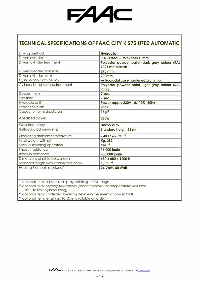
TECHNICAL SPECIFICATIONS OF FAAC CITY K 275 H700 AUTOMATIC Driving method Hydraulic Driven cylinder FE510 steel – thickness 10mm. Driven cylinder treatment Polyester powder paint, dark grey colour (RAL
7021 metallised) *1 Driven cylinder diameter 275 mm. Driven cylinder stroke 700mm Cylinder top part (head) Anticorodal case hardened aluminium Cylinder head surface treatment Polyester powder paint, light grey colour (RAL
9006) Descent time 7 sec. Rise time 7 sec. Hydraulic unit Power supply 230V +6/-10% 50Hz Protection class IP 67 Capacitor for hydraulic unit 16 μF
Absorbed power 220W
Work frequency Heavy duty Reflecting adhesive strip Standard height 55 mm.
Operating ambient temperature - 40°C + 70°C *2 Total weight with pit Kg. 387 Manual lowering operation Yes *3 Impact resistance 16,000 joule Break-in resistance 450,000 joule Dimensions of pit to be walled in 650 x 650 x 1200 H Standard length with connected cable 10 m. *4 Heating Elements (opzional) 24 Volts, 80 Watt
*1 optional item: customised spray painting in RAL range *2 optional item: heating resistances (recommended for temperatures less than –15°C to limit cylinder icing) *3 optional item: controlled lowering device in the event of power fault *4 optional item: length up to 50 m available on order
FAAC S.p.A. Via Benini, 1 40069 Zola Predosa Bologna (Italia) tel. +39 051 61724 www.faac.it
- 5 -
AUTOMATIC TRAFFIC BOLLARDS WITH PIT FAAC CITY K 275 H700 AUTOMATIC
INSTALLATION DIAGRAM
1) Dig the place where the FAAC CITY traffic bollards are to be installed checking any underground utilities in the excavation area.
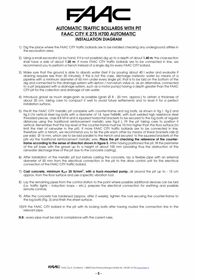
2) Using a small excavator (or by hand, if it is not possible) dig up to a depth of about 1.40 m; the cross-section shall have a side of about 1.30 m; if more FAAC CITY traffic bollards are to be connected in line, we recommend you to perform a trench instead of a single dig for every FAAC CITY bollard.
3) Make sure that the ground is able to absorb water (test it by pouring about 40 l water and evaluate if draining requires less than 30 minutes); if this is not the case, discharge meteoric water by means of a pipeline with a minimum diameter of 60 mm under every single pit, that is to be laid on the bottom of the dig and connected to the drainage system with siphon / non-return valve or, as an alternative, connected to a pit (equipped with a drainage system, such as a motor pump) having a depth greater than the FAAC CITY pit for the collection and drainage of rain water.
4) Introduce gravel as much single-grain as possible (grain Ø 8 - 20 mm. approx.) to obtain a thickness of
about 30 cm, taking care to compact it well to avoid future settlements and to level it for a perfect installation surface.
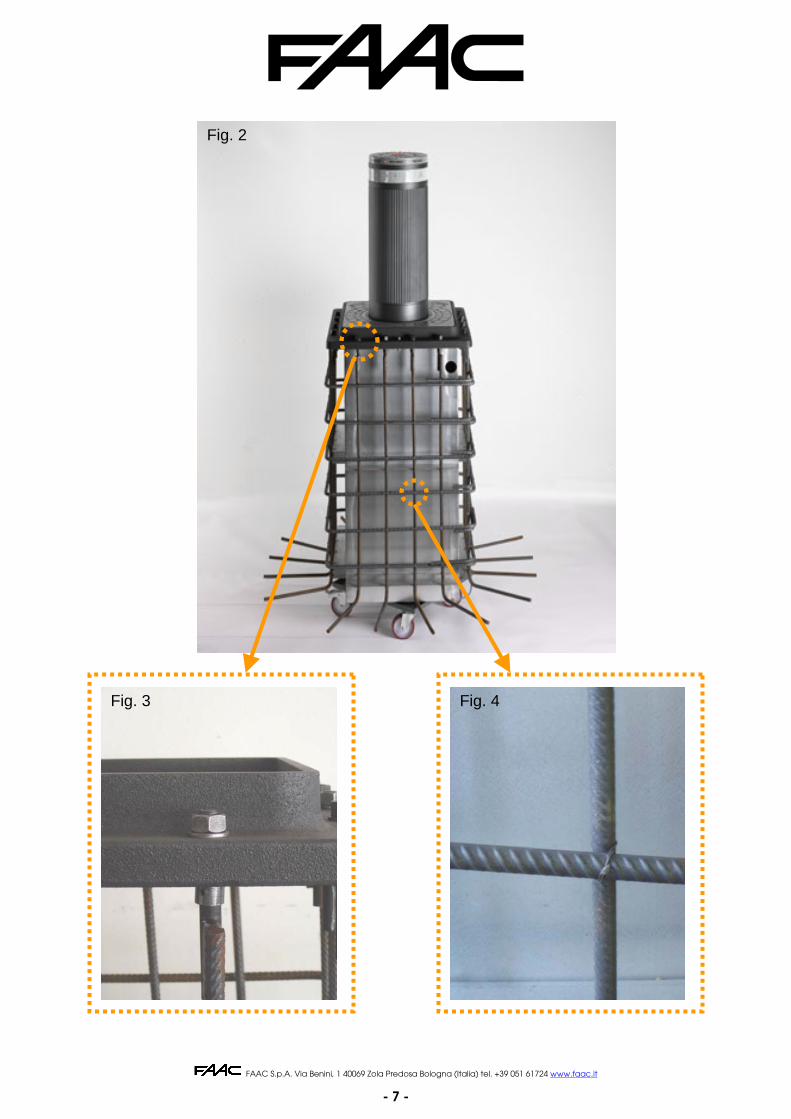
5) Pre-fit the FAAC CITY metallic pit complete with counter-frame and log bolts, as shown in fig.1, fig.2 and
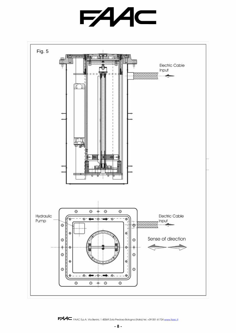
fig.3 (16 vertical steel log bolts with a diameter of 14, type FeB44K, with butt welded high resistance steel threaded pieces, class 8.8 M14 and 6 squared horizontal brackets to be secured to the log bolts at regular distances using the traditional reinforcement metallic wire Fig.4 ). Fit the pit taking care to position it vertical. Remember that the top level of the counter-frame must be 10 mm higher than the floor surface (to limit the inlet of rainwater in the pit). If more FAAC CITY traffic bollards are to be connected in line, therefore with a trench, we recommend you to tie the pits each other by means of linear brackets rails (6 per side) Ø 16 mm, which are to be laid parallel to the trench and secured to the squared brackets of the pits via the traditional reinforcement metallic wire. Place the pit checking the reference of the counter-frame according to the sense of direction shown in figure 5. After having positioned the pit, fill the perimeter of the pit base with the gravel up to a height of about 100 mm (avoiding thus the obstruction of the rainwater discharge lines of the pit due to the concrete casting).
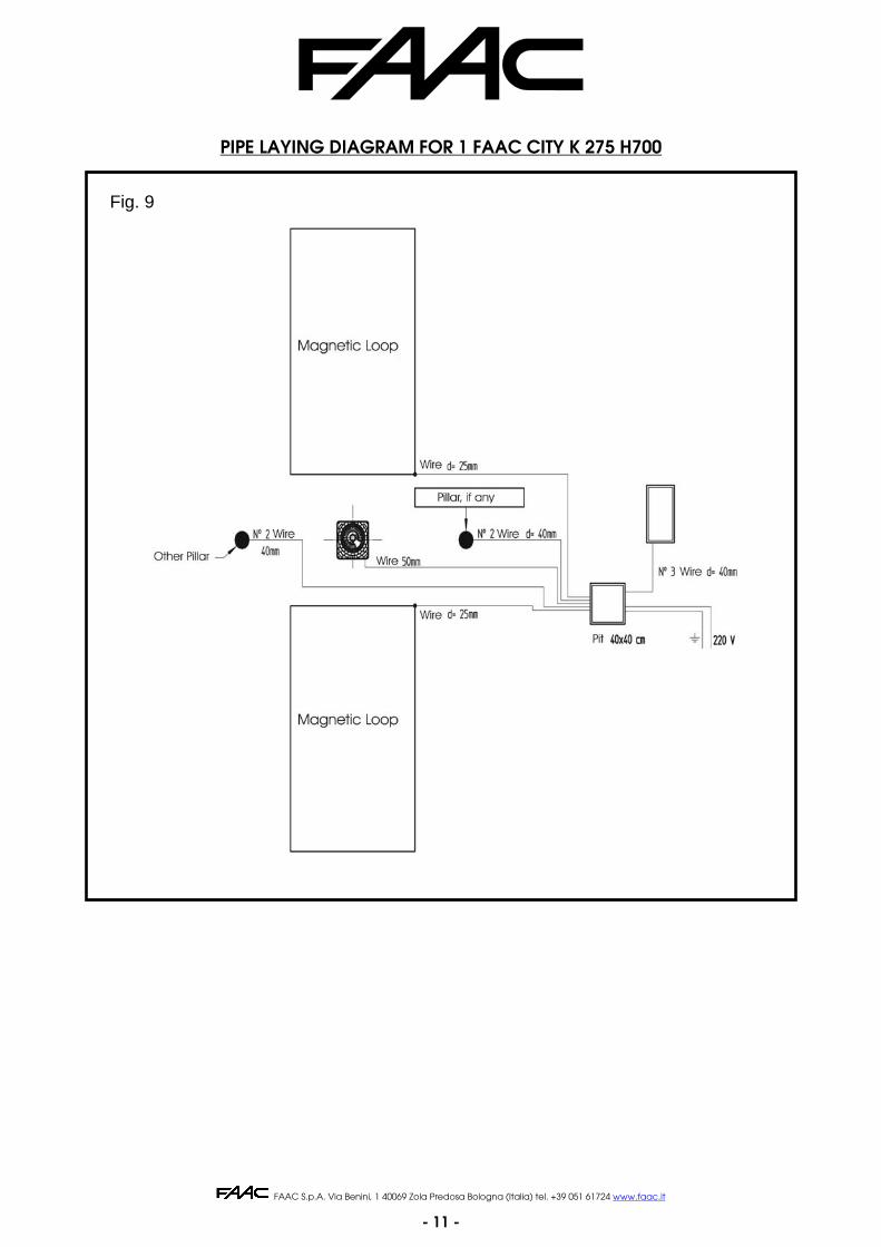
6) After installation of the metallic pit but before casting the concrete, lay a flexible pipe with an external
diameter of 50 mm from the electrical connection in the pit to the drive control unit for the electrical connection of the FAAC CITY traffic bollard.
7) Cast concrete, minimum Rck= 25 N/mm2, with a truck-mounted pump, all around the pit up to - 15 cm
approx. from the floor surface and use a specific vibration tool. 8) Lay the remaining pipes from the control station to the point where possible additional devices can be laid
(i.e. traffic lights – induction loops – etc.); prepare the electrical connection for earthing and possible remote controls.
9) After the concrete has hardened (approx. after 2 weeks), tighten the nuts securing the counter-frame to
the log bolts (Fig. 3) and finish the street surface. 10) Fit the FAAC CITY bollard in the pit with its locking bolts after having routed the connection line in the
relevant pipe. N.B.: every pipe must be laid in compliance with the current rules.
FAAC S.p.A. Via Benini, 1 40069 Zola Predosa Bologna (Italia) tel. +39 051 61724 www.faac.it
- 6 -
Fig. 1
FAAC S.p.A. Via Benini, 1 40069 Zola Predosa Bologna (Italia) tel. +39 051 61724 www.faac.it
- 7 -
Fig. 3 Fig. 4
Fig. 2
FAAC S.p.A. Via Benini, 1 40069 Zola Predosa Bologna (Italia) tel. +39 051 61724 www.faac.it
- 8 -
Fig. 5
FAAC S.p.A. Via Benini, 1 40069 Zola Predosa Bologna (Italia) tel. +39 051 61724 www.faac.it
- 9 -
POSITIONING THE SAFETY INDUCTIVE LOOPS
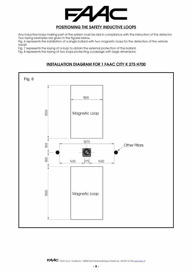
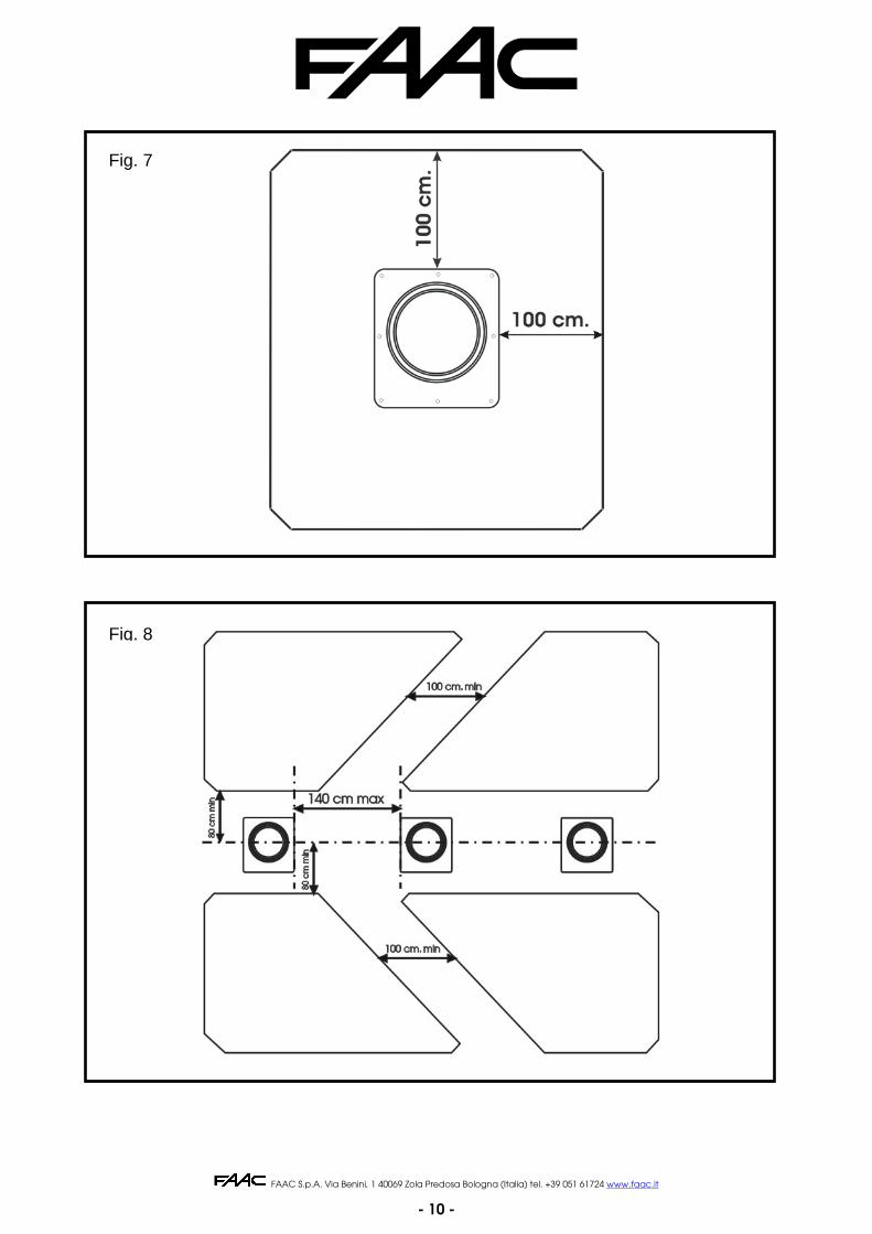
Any inductive loops making part of the system must be laid in compliance with the instruction of the detector. Two laying examples are given in the figures below. Fig. 6 represents the installation of a single bollard with two magnetic loops for the detection of the vehicle transit. Fig. 7 represents the laying of a loop to obtain the external protection of the bollard. Fig. 8 represents the laying of two loops protecting a passage with large dimensions.
INSTALLATION DIAGRAM FOR 1 FAAC CITY K 275 H700
Fig. 6
FAAC S.p.A. Via Benini, 1 40069 Zola Predosa Bologna (Italia) tel. +39 051 61724 www.faac.it
- 10 -
Fig. 7
Fig. 8
FAAC S.p.A. Via Benini, 1 40069 Zola Predosa Bologna (Italia) tel. +39 051 61724 www.faac.it
- 11 -
PIPE LAYING DIAGRAM FOR 1 FAAC CITY K 275 H700
Fig. 9
FAAC S.p.A. Via Benini, 1 40069 Zola Predosa Bologna (Italia) tel. +39 051 61724 www.faac.it
- 12 -
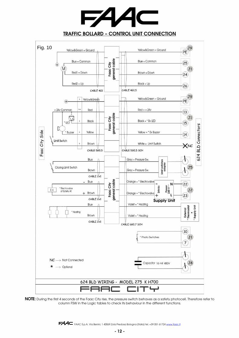
TRAFFIC BOLLARD – CONTROL UNIT CONNECTION
NOTE: During the first 4 seconds of the Faac City rise, the pressure switch behaves as a safety photocell. Therefore refer to column FSW in the Logic tables to check its behaviour in the different functions.
Fig. 10

FAAC S.p.A. Via Benini, 1 40069 Zola Predosa Bologna (Italia) tel. +39 051 61724 www.faac.it
- 13 -
CONNECTION WITH 624 BLD UNIT To control the Faac City device with the 624 BLD unit, you need to connect the internal components of the traffic bollard according to the diagram of fig. 10 (if necessary, use the connection diagram indicated in the electronic manual of the 624 BLD unit for a more complete overview of the connections) : Specifically, connect the cables coming from the safety pressure switch to the terminal board of the travel-limit adapter, as shown in the following figure:
The absence of the opening travel-limit device in the Faac City application requires you to short-circuit the J3 connector as shown in figure 11. Take great care when connecting the antiterrorism safety solenoid valve, if present. This solenoid valve, in fact, must be supplied with 24 Volt DC via an EXTERNAL POWER UNIT 230Vac-24Vdc able to supply 1.3 amp connected to the FAN output of the 624 BLD board on terminals 22 and 23 (as shown in fig. 10). The heating resistances (optional item), if any, shall be controlled via an external power unit and a thermostat, which are independent from the 624 BLD board.
PROGRAMMING THE 624 BLD CONTROL UNIT You need to change the following programming steps on the 624 BLD board (refer to chapter “PROGRAMMING” of the electronic manual of the 624 BLD board):
- set the step d F to the value 04 to install the FAAC CITY K H700. Exit the first programming level by scrolling the steps with the “F” key until you reach the status of the application without making any further changes.
The a.m. operation is indispensable and must always be carried out at the beginning of a new installation, BEFORE changing any other parameters in order to customise the application. In this way, you can set the following basic parameters to control the Faac City on the 624 BLD board:
Logic A, Pause time 30 seconds, Work Time Out 12 seconds, OUT1 output for Buzzer, OUT2 output for Head Lights and control parameters of the travel-limit/safety pressure switch.
- set the step A 8 to the value Y ( Y ) to install the closing limit switch. Exit the third programming level by scrolling the steps with the “F” key until you reach the status of the application without making any further changes.
To customise the operation of the Faac City you can now enter the first and second programming level, remembering however not to change the parameter d F that shall remain to 00. Further details and customisations can be found in the electronic manual of the 624 BLD board, which is supplied together with the application.
First programming table
Third programming table
Fig. 11
Grey = Limit switch
Grey = Limit switch

FAAC S.p.A. Via Benini, 1 40069 Zola Predosa Bologna (Italia) tel. +39 051 61724 www.faac.it
- 14 -
TECHNICAL SPECIFICATIONS OF THE FAAC CITY MASTER CONTROL STATION
Electronic control circuit With microprocessor, with specific software for controlling the FAAC CITY traffic bollards
Housing for control station Standard, wall-mounted Dimensions of housing See enclosed table
Protection class IP 55 Operating ambient temperature -15°C - 70°C
Control station power supply 230V. +6/-10% - 50Hz Protective switches Thermal-magnetic 1P + N – 6A ÷ 16A – 30mA -
6KA Service transformer 230/24 Vac 100VA
Max. quantity of PILOMATs that can be connected to the control station
Max. 10 FAAC CITY devices with simultaneous movement – the first FAAC CITY
is connected to the master unit – the remaining devices are connected to the
additional slave units – the housing dimension depends on the quantity of FAAC
CITY and on the required accessories
HOUSINGS FOR FAAC CITY TRAFFIC BOLLARDS DRIVE CONTROL STATIONS
Dimensions L x H x D
Material System configuration
WALL-MOUNTED HOUSING
320 X 400 X 160 PLAST 120° C - For basic system with 1 FAAC CITY.
WALL- MOUNTED HOUSING 400 X 480 X 160
PLAST 120° C - For system with accessories and 1 FAAC CITY.- For basic system with 2 FAAC CITY.
WALL- MOUNTED HOUSING 400 X 600 X 200
STEEL FE 37 - For system with accessories and 2 FAAC CITY.- For basic system with 3 FAAC CITY.
WALL- MOUNTED HOUSING 500 X 700 X 200
STEEL FE 37 - For system with accessories and 5 FAAC CITY.- For basic system with 8 FAAC CITY.
FLOOR COLUMN
320 X 950 X 280
Protection class IP 44
POLYESTER - For system with accessories and 2 FAAC CITY.- For basic system with 3 FAAC CITY.
LARGER DIMENSIONS ARE AVAILABLE ACCORDING TO THE SYSTEM CONFIGURATION
FAAC S.p.A. Via Benini, 1 40069 Zola Predosa Bologna (Italia) tel. +39 051 61724 www.faac.it
- 15 -
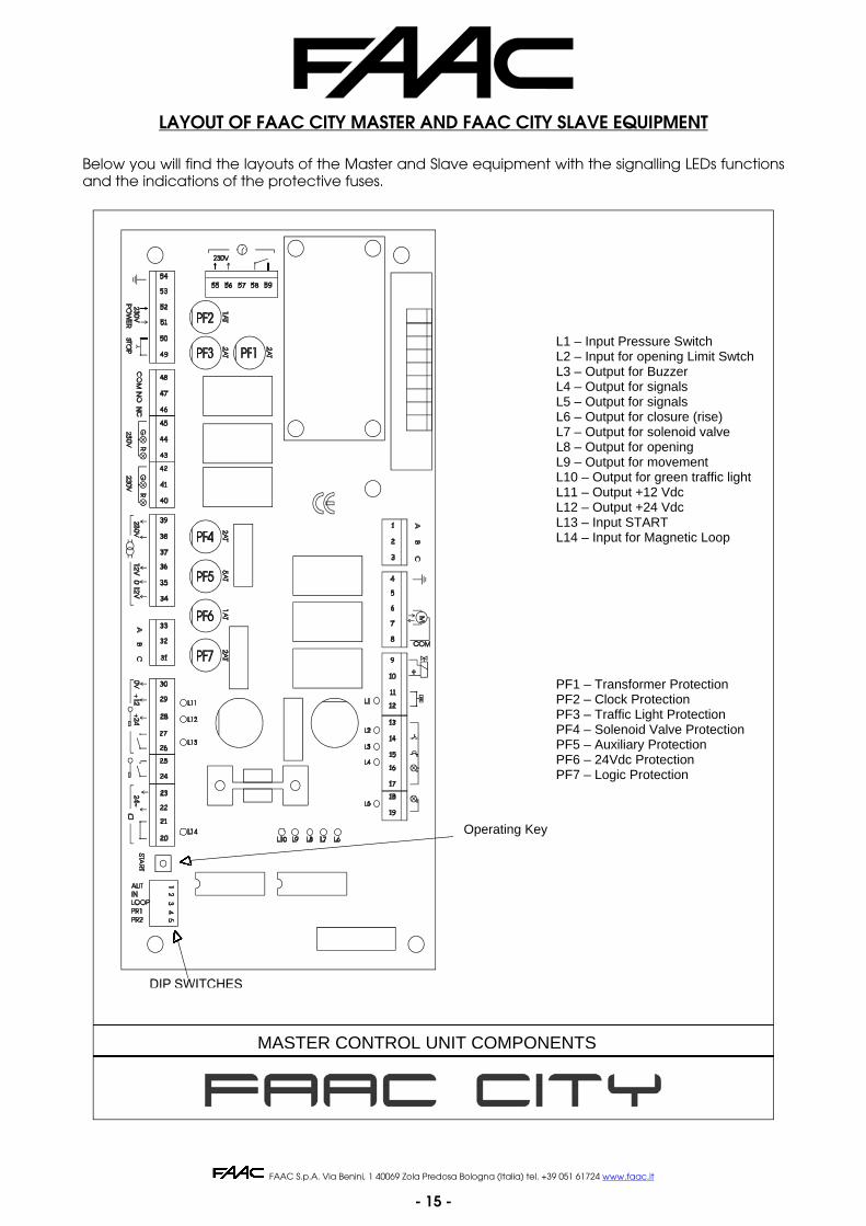
LAYOUT OF FAAC CITY MASTER AND FAAC CITY SLAVE EQUIPMENT
Below you will find the layouts of the Master and Slave equipment with the signalling LEDs functions and the indications of the protective fuses.
Apparecchiatura Master - Layout e componenti
PF1PF2PF3PF4PF5PF6PF7 - Protezione Logica
- Protezione Ausiliaria - Protezione Elettrovalvola - Protezione Semaforo
- Protezione Trasformatore
- Protezione Ausiliaria 24V
- Protezione Orologio
L1 L2 L3 L4 L5 L6 L7 L8L9 L10L11L12 L13L14 - Input Spira di sicurezza
- Input Start - (Out) + 24V c.c. OK - (Out) + 12V c.c. OK - Out Semaforo Verde - Out Movimento - Out In Apertura (abbassamento) - Out Elettrovalvola - Out in Chiusura (sollevamento) - Out Segnalazione (fisso) - Out Segnalazione (mobile) - Out Segnalatore acustico - Input FC Apertura - Input Pressostato
TASTO DI AZIONAMENTO
L1 – Input Pressure Switch L2 – Input for opening Limit SwtchL3 – Output for Buzzer L4 – Output for signals L5 – Output for signals L6 – Output for closure (rise) L7 – Output for solenoid valve L8 – Output for opening L9 – Output for movement L10 – Output for green traffic light L11 – Output +12 Vdc L12 – Output +24 Vdc L13 – Input START L14 – Input for Magnetic Loop
PF1 – Transformer Protection PF2 – Clock Protection PF3 – Traffic Light Protection PF4 – Solenoid Valve Protection PF5 – Auxiliary Protection PF6 – 24Vdc Protection PF7 – Logic Protection
Operating Key
MASTER CONTROL UNIT COMPONENTS

FAAC S.p.A. Via Benini, 1 40069 Zola Predosa Bologna (Italia) tel. +39 051 61724 www.faac.it
- 16 -
L1 L2L3
PF1PF2 - Protezione Trasformatore
- Protezione Ausiliaria
- (Out) + 24V c.c. OK - Input Finecorsa Apertura - Input Pressostato
Apparecchiatura Slave - Layout e componenti
Connettore collegamentoMaster/SlaveSlave/Slave
Connettore collegamentoSlave/Slave
SLAVE CONTROL UNIT COMPONENTS
Connector between Master & Slave
Connector between Slave & Slave
L1 – Input for pressure switch L2 – Input for opening limit switch L3 – 24 Vdc PF1 – Auxiliary protection PF2 – Transformer protection
FAAC S.p.A. Via Benini, 1 40069 Zola Predosa Bologna (Italia) tel. +39 051 61724 www.faac.it
- 17 -
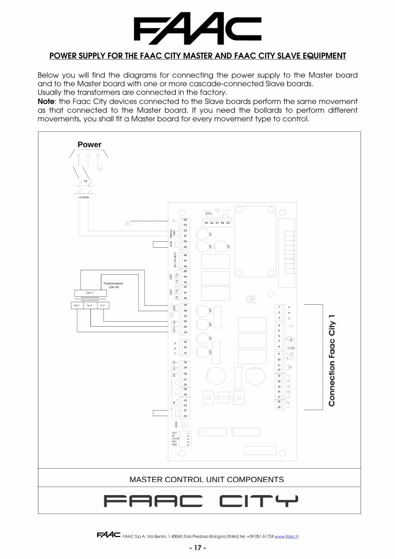
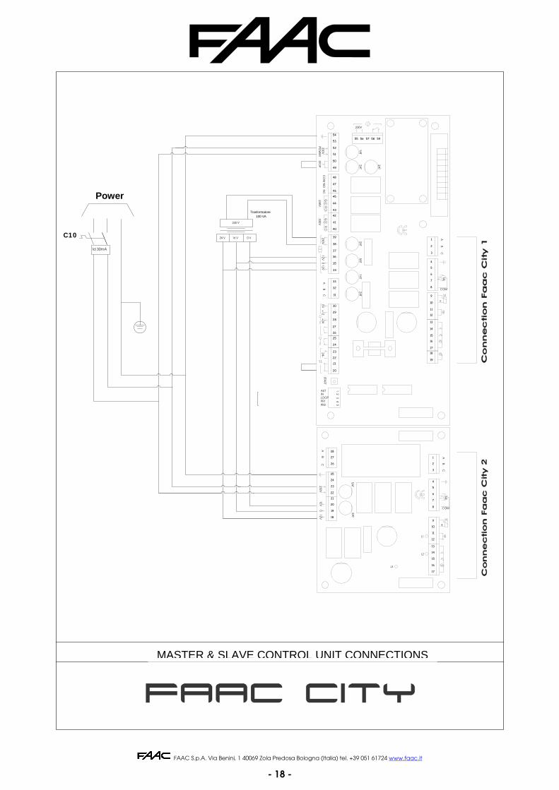
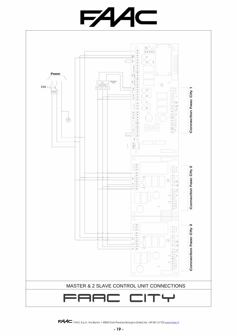
POWER SUPPLY FOR THE FAAC CITY MASTER AND FAAC CITY SLAVE EQUIPMENT
Below you will find the diagrams for connecting the power supply to the Master board and to the Master board with one or more cascade-connected Slave boards. Usually the transformers are connected in the factory. Note: the Faac City devices connected to the Slave boards perform the same movement as that connected to the Master board. If you need the bollards to perform different movements, you shall fit a Master board for every movement type to control.
Linea 230V
C6
Id 30mA
Trasformatore100 VA
24 V 16 V 0 V
230 V
Col
lega
men
to F
aac
Cit
y
Predisposizione N.C. Rilevatore induttivo Opzionale
Predisposizione N.C. Pulsante sgancio di emergenza
PR2PR1LOOPINAUT
45
START
32
1
24~+24
0V+12
20
26
21
22
23
24
25
27
28
29
30
50STOP
CB
A12V
12V0
230V230V
230V
RG
RG
CO
MN
CN
O
40
35
31
32
33
34
36
37
38
39
45
41
42
43
44
49
46
47
48
POW
ER230V
52
53
54
51
+
++
+
PR
18
19
17
16
15
12
14
13
11
10
2AT
1AT
5AT
2AT
2AT
2AT
COM
MC
AB
7
9
8
6
5
2
4
3
1
230V
1AT
55 56 57 58 59
Apparecchiatura Master - Alimentazione
MASTER CONTROL UNIT COMPONENTS
Power
FAAC S.p.A. Via Benini, 1 40069 Zola Predosa Bologna (Italia) tel. +39 051 61724 www.faac.it
- 18 -
Apparecchiature Master e Slave - Alimentazione
Linea 230V
C10
Id 30mA
Trasformatore100 VA
24 V 16 V 0 V
230 V
Col
lega
men
to F
aac
Cit
y 1
Predisposizione N.C. Rilevatore induttivo Opzionale
Predisposizione N.C. Pulsante sgancio di emergenza
Col
lega
men
to F
aac
Cit
y 2
PR2PR1LOOPINAUT
45
STAR
T
32
1
24~+
240V
+12
20
26
21
22
23
24
25
27
28
29
30
50STOP
CB
A12V
12V0
230V230V
230V
RG
RG
CO
MN
CN
O
40
35
31
32
33
34
36
37
38
39
45
41
42
43
44
49
46
47
48
POW
ER230V
52
53
54
51
+
++
+
PR
18
19
17
16
15
12
14
13
11
10
2AT
1AT
5AT
2AT
2AT
2AT
COM
MC
AB
7
9
8
6
5
2
4
3
1
230V
1AT
55 56 57 58 59
L3
5AT
12V12V
0230V
2AT
AC
B
L2
++
+M
COM
L1
PR
CB
A
23
19
18
20
22
21
28
24
25
27
26
14
15
17
16
9
12
11
10
13
5
6
8
7
3
2
1
4
MASTER & SLAVE CONTROL UNIT CONNECTIONS
Power
FAAC S.p.A. Via Benini, 1 40069 Zola Predosa Bologna (Italia) tel. +39 051 61724 www.faac.it
- 19 -
Linea 230V
C10
Id 30mA
24 V 16 V 0 V
230 V
Col
lega
men
to F
aac
Cit
y1
Predisposizione N.C. Rilevatore induttivo Opzionale
Predisposizione N.C. Pulsante sgancio di emergenza
Col
lega
men
to F
aac
Cit
y 2
Col
lega
men
to F
aac
Cit
y 3
PR2PR1LOOPINAUT
45
STAR
T
32
1
24~+
240V
+12
20
26
21
22
23
24
25
27
28
29
30
50STOP
CB
A12V
12V0
230V230V
230V
RG
RG
CO
MN
CN
O
40
35
31
32
33
34
36
37
38
39
45
41
42
43
44
49
46
47
48
POW
ER230V
52
53
54
51
+
++
+
PR
18
19
17
16
15
12
14
13
11
10
2AT
1AT
5AT
2AT
2AT
2AT
COM
MC
AB
7
9
8
6
5
2
4
3
1
230V
1AT
55 56 57 58 59
L3
5AT
12V12V
0230V
2AT
AC
B
L2
++
+M
COM
L1
PRC
BA
L3
++
B0
12VC
12V230V
A
2AT
5AT
+
COM
AB
CM
L1
L2
PR
Trasformatore100 VA
23
19
18
20
22
21
28
24
25
27
26
14
15
17
16
9
12
11
10
13
5
6
8
7
3
2
1
4
15
16
17
27
18
19
26
25
24
21
22
20
23
28
1
4
2
3
7
8
6
5
13
10
11
12
9
14
Apparecchiature Master e 2 Slave - Alimentazione
MASTER & 2 SLAVE CONTROL UNIT CONNECTIONS
Power
FAAC S.p.A. Via Benini, 1 40069 Zola Predosa Bologna (Italia) tel. +39 051 61724 www.faac.it
- 20 -
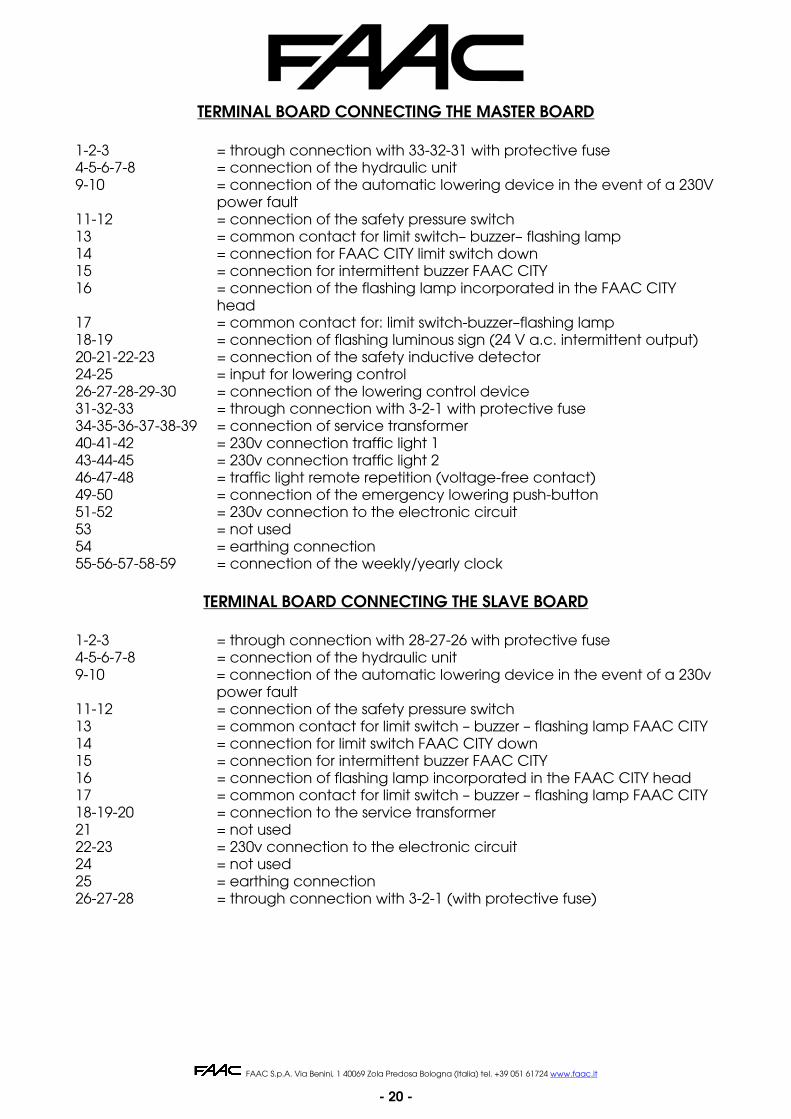
TERMINAL BOARD CONNECTING THE MASTER BOARD 1-2-3 = through connection with 33-32-31 with protective fuse 4-5-6-7-8 = connection of the hydraulic unit 9-10 = connection of the automatic lowering device in the event of a 230V
power fault 11-12 = connection of the safety pressure switch 13 = common contact for limit switch– buzzer– flashing lamp 14 = connection for FAAC CITY limit switch down 15 = connection for intermittent buzzer FAAC CITY 16 = connection of the flashing lamp incorporated in the FAAC CITY
head 17 = common contact for: limit switch-buzzer–flashing lamp 18-19 = connection of flashing luminous sign (24 V a.c. intermittent output) 20-21-22-23 = connection of the safety inductive detector 24-25 = input for lowering control 26-27-28-29-30 = connection of the lowering control device 31-32-33 = through connection with 3-2-1 with protective fuse 34-35-36-37-38-39 = connection of service transformer 40-41-42 = 230v connection traffic light 1 43-44-45 = 230v connection traffic light 2 46-47-48 = traffic light remote repetition (voltage-free contact) 49-50 = connection of the emergency lowering push-button 51-52 = 230v connection to the electronic circuit 53 = not used 54 = earthing connection 55-56-57-58-59 = connection of the weekly/yearly clock
TERMINAL BOARD CONNECTING THE SLAVE BOARD 1-2-3 = through connection with 28-27-26 with protective fuse 4-5-6-7-8 = connection of the hydraulic unit 9-10 = connection of the automatic lowering device in the event of a 230v
power fault 11-12 = connection of the safety pressure switch 13 = common contact for limit switch – buzzer – flashing lamp FAAC CITY 14 = connection for limit switch FAAC CITY down 15 = connection for intermittent buzzer FAAC CITY 16 = connection of flashing lamp incorporated in the FAAC CITY head 17 = common contact for limit switch – buzzer – flashing lamp FAAC CITY 18-19-20 = connection to the service transformer 21 = not used 22-23 = 230v connection to the electronic circuit 24 = not used 25 = earthing connection 26-27-28 = through connection with 3-2-1 (with protective fuse)
FAAC S.p.A. Via Benini, 1 40069 Zola Predosa Bologna (Italia) tel. +39 051 61724 www.faac.it
- 21 -
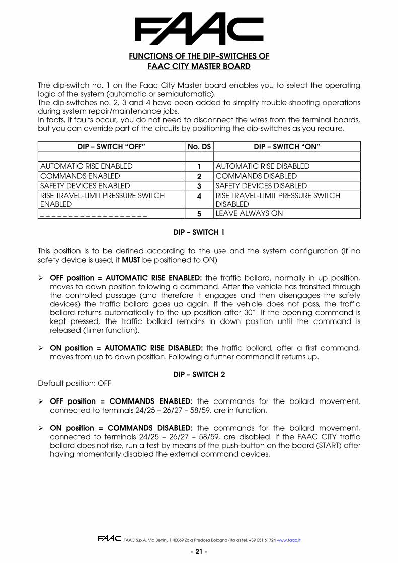
FUNCTIONS OF THE DIP–SWITCHES OF FAAC CITY MASTER BOARD
The dip-switch no. 1 on the Faac City Master board enables you to select the operating logic of the system (automatic or semiautomatic). The dip-switches no. 2, 3 and 4 have been added to simplify trouble-shooting operations during system repair/maintenance jobs. In facts, if faults occur, you do not need to disconnect the wires from the terminal boards, but you can override part of the circuits by positioning the dip-switches as you require.
DIP – SWITCH “OFF” No. DS DIP – SWITCH “ON”
AUTOMATIC RISE ENABLED 1 AUTOMATIC RISE DISABLED COMMANDS ENABLED 2 COMMANDS DISABLED SAFETY DEVICES ENABLED 3 SAFETY DEVICES DISABLED RISE TRAVEL-LIMIT PRESSURE SWITCH ENABLED
4 RISE TRAVEL-LIMIT PRESSURE SWITCH DISABLED
_ _ _ _ _ _ _ _ _ _ _ _ _ _ _ _ _ _ _ 5 LEAVE ALWAYS ON
DIP – SWITCH 1
This position is to be defined according to the use and the system configuration (if no safety device is used, it MUST be positioned to ON) OFF position = AUTOMATIC RISE ENABLED: the traffic bollard, normally in up position,
moves to down position following a command. After the vehicle has transited through the controlled passage (and therefore it engages and then disengages the safety devices) the traffic bollard goes up again. If the vehicle does not pass, the traffic bollard returns automatically to the up position after 30”. If the opening command is kept pressed, the traffic bollard remains in down position until the command is released (timer function).
ON position = AUTOMATIC RISE DISABLED: the traffic bollard, after a first command,
moves from up to down position. Following a further command it returns up.
DIP – SWITCH 2 Default position: OFF OFF position = COMMANDS ENABLED: the commands for the bollard movement,
connected to terminals 24/25 – 26/27 – 58/59, are in function. ON position = COMMANDS DISABLED: the commands for the bollard movement,
connected to terminals 24/25 – 26/27 – 58/59, are disabled. If the FAAC CITY traffic bollard does not rise, run a test by means of the push-button on the board (START) after having momentarily disabled the external command devices.
FAAC S.p.A. Via Benini, 1 40069 Zola Predosa Bologna (Italia) tel. +39 051 61724 www.faac.it
- 22 -
DIP – SWITCH 3:
Default position: OFF OFF position = SAFETY DEVICES ENABLED: the inputs for the safety devices (terminals
20/21) are enabled. If no safety devices are fitted, jumper connect terminals 20 and 21.
ON position = SAFETY DEVICES DISABLED: the input for the safety devices (terminals
20/21) is disabled. If the FAAC CITY traffic bollard does not rise, you can momentarily disable the safety devices to check if the fault is caused by them.
Note: to fit devices for the detection of metallic masses, please refer to the instructions of the traffic bollard and to the instructions of the single devices.
DIP – SWITCH 4: Default position: OFF OFF position = RISE TRAVEL-LIMIT PRESSURE SWITCH ENABLED: in the final rising phase, the
signal from the pressure switch is used as rise travel-limit. ON position = RISE TRAVEL-LIMIT PRESSURE SWITCH DISABLED: the a.m. function is
disabled. The rise command is kept for the entire duration of the time-out time (cannot be changed).
DIP – SWITCH 5:
Default position: ON Leave always ON.
THE FOLLOWING CHECKS ARE ALSO TO BE PERFORMED:
Check the operation of the flashing lamp incorporated in the bollard head
Check the operation of the safety inductive loops
Check the operation of the command radio receiver
Visual check of the control unit
FINAL OPERATIONS
After installation, check the correct operation of the traffic bollard, paying special
attention to the safety devices, if any.
FAAC S.p.A. Via Benini, 1 40069 Zola Predosa Bologna (Italia) tel. +39 051 61724 www.faac.it
- 23 -
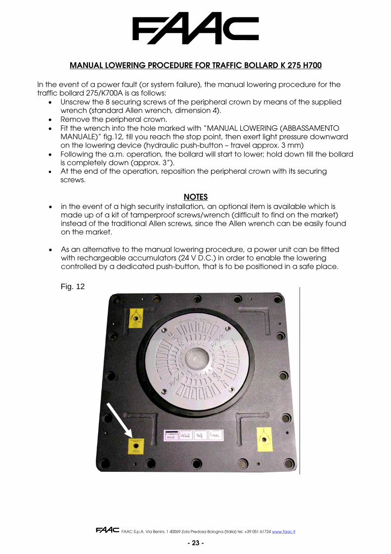
MANUAL LOWERING PROCEDURE FOR TRAFFIC BOLLARD K 275 H700
In the event of a power fault (or system failure), the manual lowering procedure for the traffic bollard 275/K700A is as follows:
• Unscrew the 8 securing screws of the peripheral crown by means of the supplied wrench (standard Allen wrench, dimension 4).
• Remove the peripheral crown. • Fit the wrench into the hole marked with “MANUAL LOWERING (ABBASSAMENTO
MANUALE)” fig.12, till you reach the stop point, then exert light pressure downward on the lowering device (hydraulic push-button – travel approx. 3 mm)
• Following the a.m. operation, the bollard will start to lower; hold down till the bollard is completely down (approx. 3”).
• At the end of the operation, reposition the peripheral crown with its securing screws.
NOTES
• in the event of a high security installation, an optional item is available which is made up of a kit of tamperproof screws/wrench (difficult to find on the market) instead of the traditional Allen screws, since the Allen wrench can be easily found on the market.
• As an alternative to the manual lowering procedure, a power unit can be fitted
with rechargeable accumulators (24 V D.C.) in order to enable the lowering controlled by a dedicated push-button, that is to be positioned in a safe place.
Fig. 12

FAAC S.p.A. Via Benini, 1 40069 Zola Predosa Bologna (Italia) tel. +39 051 61724 www.faac.it
- 24 -
STANDARD PROCEDURE FOR A 6-MONTHLY ORDINARY MAINTENANCE OF CONCEILING TRAFFIC BOLLARD FAAC CITY 275 H600 and 275 H800:
Ordinary maintenance standard procedure:
Clean the pit and remove any settled material by suction
Clean the water drainage systems on the pit bottom
Clean and lubricate the central sliding guide
Check (and replace, if necessary) the bottom limit-stop gaskets
Check (and repair, if necessary) any oil leakages from the driving piston
Check the correct tightening of the bollard screws
Clean the driven cylinder and touch up paint, if necessary
Check the hydraulic unit and top up oil, if necessary. Check the setting of the
operating pressure
Check and set, if necessary, the functions of the safety pressure switch (40 Kg.)
Test the thermal-magnetic switch upstream of the system using the suitable instrument
(loop tester, ) both for insulation and continuity.
Test the value (earth resistance) and earth continuity using the suitable instruments
(loop testers).

FAAC S.p.A. Via Benini, 1 40069 Zola Predosa Bologna (Italia) tel. +39 051 61724 www.faac.it
- 25 -
7328
58 re
v. C
Distributor’s stamp:
FAAC S.p.A. Via Benini, 1 40069 Zola Predosa (BO) – ITALIA Tel.: 051/61724 - Fax: 051/758518 www.faac.it
The descriptions and illustrations in this manual are not binding. While leaving the essential characteristics of the equipment unaltered, FAAC reserves the right, at any time and without having to update this publication, to make the modifications which it considers convenient for technical improvements or for any other construction or commercial requirements.