automatic code generation of mvc web applications
TRANSCRIPT

computers
Article
Automatic Code Generation of MVCWeb Applications
Gaetanino Paolone 1, Martina Marinelli 1, Romolo Paesani 1 and Paolino Di Felice 2,*1 Software Industriale, 64100 Teramo, Italy; [email protected] (G.P.);
[email protected] (M.M.); [email protected] (R.P.)2 Department of Industrial and Information Engineering and Economics, University of L’Aquila,
67100 L’Aquila, Italy* Correspondence: [email protected]; Tel.: +39-320-423-2540
Received: 18 June 2020; Accepted: 10 July 2020; Published: 15 July 2020�����������������
Abstract: As Web applications become more and more complex, the development costs are increasingas well. A Model Driven Architecture (MDA) approach is proposed in this paper since it simplifiesmodeling, design, implementation, and integration of applications by defining software mainlyat the model level. We adopt the The Unified Modeling Language (UML), as modeling language.UML provides a set of diagrams to model structural and behavioral aspects of the Web applications.Automatic translation of UML diagrams to the Object-Oriented code is highly desirable because iteliminates the chances of introducing human errors. Moreover, automatic code generation helps thesoftware designers delivering of the software on time. In our approach, the automatic transformationsacross the MDA’s levels are based on meta-models for two of the most important constructs of UML,namely Use Cases and classes. A proprietary tool (called xGenerator) performs the transformationsup to the Java source code. The architecture of the generated Web applications respects a variant ofthe well-known Model-View-Controller (MVC) pattern.
Keywords: Model Driven Engineering; Model Driven Architecture; UML; model; meta-model;Model-View-Controller; xGenerator; Web application
1. Introduction
Enterprise Web applications are an essential part of the computer-based information system ofmost organizations. They provide business-oriented tools such as online payment processing andautomated billing systems. The main goal of enterprise Web applications is to improve companyproductivity and efficiency through business logic support functionality. Those applications performbusiness functions including order processing, accounting and customer relationship management.
The development of Web applications is a challenging goal [1]. For an IT project to be successful,it must reproduce, as much as possible, the business context, in such a way corporate employees canrecognize in the software their daily modus operandi—each “actor” plays a set of “use cases” withinan organization regardless of automation.
In general terms, a Use Case (UC) is a sequence of interactions between systems and users in aparticular environment to achieve a specific goal. A UC may have multiple “paths” that can be takenat any one time. A UC scenario is a single path through an UC. In the Unified Modeling Language(UML), “UCs are a means to capture the requirements of systems, that is, what systems are supposedto do. [. . . ] A UC is a specification of a behavior.” [2], p. 639.
The biggest innovation brought by the UC construct is that it exists in the business contextindependently from the automation process—the software designer only needs to discover UCs inthe enterprise system and then reproduce them in the software application. In 2008, Paolone et al. [3]
Computers 2020, 9, 56; doi:10.3390/computers9030056 www.mdpi.com/journal/computers

Computers 2020, 9, 56 2 of 29
proposed a methodology that helps reproducing UCs and objects of the business domain into theenterprise Web application. In that work, the authors treat UCs as the main pillar for the Webapplication development, since they are the central concept of the business model. Despite theexcellent book by Armour and Miller published in 2000 [4], very recently Ciccozzi et al. [5] haveverified that UML UC diagrams are rarely used in the development of complex software projects.Class (48/82), state machine (36/82), and activity (33/82) diagrams are the most commonly used, oftenin combination; while just 3/82 entries adopt UC diagrams. Eighty-two is the number of entries(63 research studies and 19 tools) that have been selected in the study.
Paolone et al. [6,7] reshaped the point of view in Reference [3] in a novel use-case-drivenmethodology, within the general frame of reference of the Model-Driven Architecture (MDA). “MDAis an approach to software design, development and implementation by the OMG. MDA providesguidelines for structuring software specifications that are expressed as models. MDA separates businessand application logic from the underlying platform technology.” (Sentences taken from: https://www.omg.org/mda/) MDA enables model-driven software development which treats models asprimary development artefacts. Model-Driven Development (MDD), Model-Driven Engineering(MDE), Model-Driven Software Development (MDSD), and MD* are terms used for referring to theexisting approaches to model-driven development [8].
The present work concludes a long and engaging journey started with Reference [3] in whichresearch, implementation and validation (mostly business Web applications for banking) have beenjoined together. The paper describes an automatic process to develop enterprise Web applications.The frame of reference is still MDA, but the pillars of the proposal are, besides the UCs, class andsequence diagrams. These diagrams cover, in order, the structure and the behavior of the system tobe developed, as well as their interactions. In this way, all the system requirements that the OMGrecommends are satisfied. The methodological process ensures the continuity between businessmodeling, system modeling, design, and implementation. This lays the foundation for the mapping ofthe behavioral business model into a consistent software that meets the requirements.
Several scholars have investigated the state of applying MDE in the industry and the factorsconsidered relevant for its adoption, for example, References [9–13]. For example, Cuadrado et al. [12]write: “MDE is increasingly gaining acceptance in the software engineering community, howeverits adoption by the industry is far from successful. The number of companies applying MDE is stillvery limited.”. Analogously, Cabot and Kolovos [14] write—“Model-driven engineering has not beenadopted by industry as extensively as many expected.” Below, we mention, among the many, from pastto present three papers that have pointed out the shortcomings of MDE that hamper it diffusionin industry. Mahmood et al. [15] write—“Currently, Model-to-Code transformation relies on thetransformation rules, meta models and transformation languages, making the transformation processcomplex and lengthy.” Moreover, they say that—“in reality, it is a difficult, tricky and time-consumingtask to define and maintain a completely accurate rule set, especially in the availability of little domainknowledge.” On the same topic, Mussbacher et al. [16] say that despite MDE is a well-known approachfor developing complex software systems, it is “still a niche technology”. While modeling languages,like for example UML, are widespread, “the use of models to automatically generate software systemsis still relatively rare”. Very recently, Bucchiarone et al. [17] confirmed that model transformationsare one of the grand challenges in the MDE field. They point out that the usability of the currentmodel transformation techniques, particularly the model-to-model model transformations, needs to beincreased. Despite the powerful features of the today available transformation languages (e.g., ATL,QVT, ETL, etc.), their adoption in the industry is, in fact, still marginal [17]. Among the adverse factors,the semantic intricacy of those languages hampers their diffusion. Moreover, model transformationsare not necessarily deterministic, and this prevents the implementors from having full control on thegenerated solution.
To sidestep the mentioned pitfalls, we implemented a proprietary tool (called xGenerator) whichperforms the transformations from the CIM level up to the Java code of the Web application. In our
Computers 2020, 9, 56 3 of 29
approach, analysts and designers are charged with the construction of models at CIM, while PIM,PSM and the Code are automatically generated. The transformations across levels of MDA are basedon meta-models for two of the most important constructs of UML—UCs and classes. The adoptedmeta-models and the transformation algorithms are embedded inside xGenerator and analysts anddesigners do not need to care about. The architecture of the generated source code, of the enterpriseWeb application, respects a variant of the MVC pattern.
The paper is structured as follows. Section 2 introduces notions and terms used throughout thepaper. Section 3 presents the proposed methodological process. A case study is given in Section 4to illustrate the approach. Section 5 is about the comparison with the related work, while Section 6concludes the paper with a look to the future work. An Appendix completes the paper.
2. Background
This section collects notions and concepts used in the paper.A model is a simplified abstract view of a complex reality. It may focus on particular views,
enforcing the divide and conquer principle for a compound problem. In the business domain, a modelrepresents how the business functions. In other words, we can say that a business model is "the how" ofthe business. It is a high level description of factors like how to add value, target customers, partners,costs, and so forth. So, an (enterprise) business model is a model of its business. Last but not least,a model must have a purpose. For a business, the purpose may be understanding its structure or itsbehavior. The term system model denotes a software system that (in some way) automates the business.
A meta-model is a model of a model. It defines the modeling language, that is, the constructsthat can be used to express models. It defines (a) the object types that can be used to represent amodel; (b) the relations between object types; (c) the attributes of the object types; (d) the rules tocombine object types and relations. The meta-model is the abstract syntax, the modeling language isthe concrete syntax.
Modeling′s aim is representing all relevant aspects of a domain in a defined language. The resultof modeling is a model. A modeling language specifies the building blocks (elements) from which amodel can be made. The meta-modeling is the process of generating meta-models. A meta-meta-modeldefines the language in which a meta-model can be expressed.
The Unified Modeling Language (UML) Standardized by the Object Management Group (OMG) in1997, UML is both a de facto and a de jure standard in industrial development of software systems,as reiterated in recent publications (e.g., References [5,18]).
UML diagrams provide a visual representation of an aspect of a system. They illustrate thequantifiable aspects of a software system that can be described visually, such as behavior, structure,relationships, and functionality. The visual representation of a software system that UML diagramsprovide can offer both low-level and high-level insight into the concept and design of an application.In UML 2.5 diagrams are grouped in three categories [2]:
• Structure Diagrams (describe the structure of a system): Class Diagram, Component Diagram,Object Diagram, Profile Diagram, Composite Structure Diagram, Deployment Diagram,Package Diagram.
• Behavior Diagrams (describe the behavior of a system): Activity Diagram, Use Case Diagram,State Machine Diagram.
• Interaction Diagrams (relate the structural part of a system to the behavioral part): SequenceDiagram, Communication Diagram, Timing Diagram.
UML models represent software systems at different levels of detail. UML models containmodel elements (such as actors, use cases and classes) and one or more diagrams that show a specificperspective of a system. A model can also contain other, more detailed models. A typical UML modelcan consist of many different types of diagrams, with each diagram presenting a different view of thesoftware system under modeling. UML models are abstract representations of a software system.

Computers 2020, 9, 56 4 of 29
A Process is a logical sequence of tasks performed to achieve a particular objective. A processdefines what is to be done, without specifying how each task is performed. A software developmentprocess is composed of a sequence of tasks devoted to develop a software system.
The Model-View-Controller (MVC) Figure 1 shows the MVC pattern applied to an enterprise Webapplication. The rectangles with rounded corners are part of the standard MVC pattern [19]. Each layeris composed of classes. The latter implement the interactions among the three layers. The Controllerinteracts with the Model in order to retrieve the needed data and generates the View. The View isresponsible of the management of the graphical user interface; this layer controls the way data isdisplayed and how the user interacts with it. It also provides ways for data gathering from the users.The Model layer implements the business logic of the application. It encapsulates methods to accessdata into the databases. The Browser displays the HTML produced by the View classes and sendsrequests to the Controller.
Figure 1. The Model-View-Controller (MVC) pattern of an enterprise Web application.
The Unified Process is an iterative and incremental process for the development of general purposesoftware. The best-known refinement of the Unified Process is the Rational Unified Process. The latter isdivided into disciplines: Business Modeling, Requirements, Analysis and Design, Implementation,Test, Deployment, Configuration and Change Management, Project Management, and Environment[20]. In the present work, the first four disciplines of the Rational Unified Process are used.
Model Driven Architecture (MDA) provides guidelines for structuring software specificationsthat are expressed as models. In Reference [21], the term application is used to refer to a softwarefunctionality being developed. OMG MDA defines a platform as “a set of subsystems and technologiesthat provide a coherent set of functionality through interfaces and specified usage patterns, which anyapplication supported by that platform can use without concern for the details of how the functionalityprovided by the platform is implemented”.
The MDA is structured in terms of the three models recalled below:
• Computation Independent Model (CIM) – It ignores details of the structure of the software system.A CIM is sometimes called a domain model.
• Platform Independent Model (PIM) – It exhibits a certain degree of platform independence so as tobe suitable for use with a number of different platforms of similar type.
• Platform Specific Model (PSM) – It combines the specifications in the PIM with the details thatspecify how the software system uses a particular type of platform.
The transition between the CIM, PIM and PSM models and finally the Code is possible throughthe execution of model transformations. A transformation converts models from one level of abstractionto another, usually from a more abstract to less abstract view, by adding more detail supplied by thetransformation rules. Transformations can be Model to Model (it concerns the transition from CIM toPIM or from PIM to PSM) and Model to Text (it concerns the generation of the code from the PSM to aspecific programming language as a target). Reference [18] reports about the state-of-the-art of codegeneration using MDA research in software engineering.
The following sentences about code generators and generation techniques are borrowed fromSection 2.4 of the book by Sven Jörges [8].
Code generators automatically derive an implementation from the model, so they allow realmodel-driven software development. Code generators relate to models as compilers relate to high-level
Computers 2020, 9, 56 5 of 29
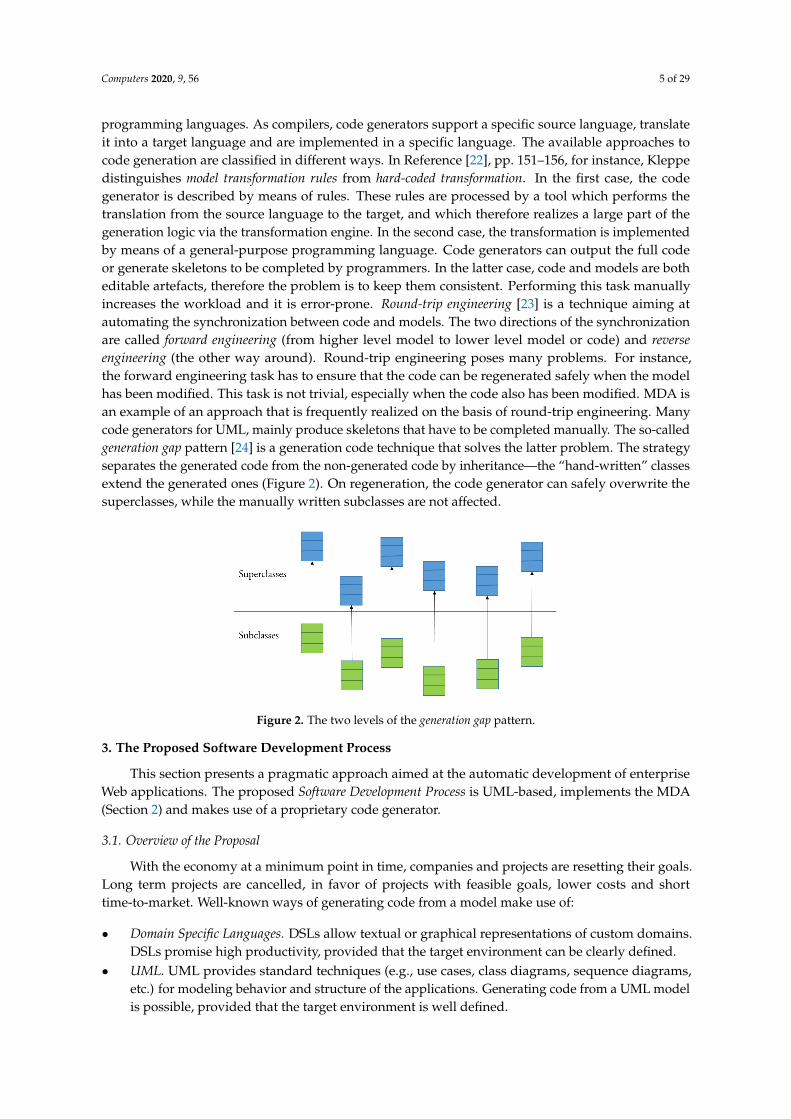
programming languages. As compilers, code generators support a specific source language, translateit into a target language and are implemented in a specific language. The available approaches tocode generation are classified in different ways. In Reference [22], pp. 151–156, for instance, Kleppedistinguishes model transformation rules from hard-coded transformation. In the first case, the codegenerator is described by means of rules. These rules are processed by a tool which performs thetranslation from the source language to the target, and which therefore realizes a large part of thegeneration logic via the transformation engine. In the second case, the transformation is implementedby means of a general-purpose programming language. Code generators can output the full codeor generate skeletons to be completed by programmers. In the latter case, code and models are botheditable artefacts, therefore the problem is to keep them consistent. Performing this task manuallyincreases the workload and it is error-prone. Round-trip engineering [23] is a technique aiming atautomating the synchronization between code and models. The two directions of the synchronizationare called forward engineering (from higher level model to lower level model or code) and reverseengineering (the other way around). Round-trip engineering poses many problems. For instance,the forward engineering task has to ensure that the code can be regenerated safely when the modelhas been modified. This task is not trivial, especially when the code also has been modified. MDA isan example of an approach that is frequently realized on the basis of round-trip engineering. Manycode generators for UML, mainly produce skeletons that have to be completed manually. The so-calledgeneration gap pattern [24] is a generation code technique that solves the latter problem. The strategyseparates the generated code from the non-generated code by inheritance—the “hand-written” classesextend the generated ones (Figure 2). On regeneration, the code generator can safely overwrite thesuperclasses, while the manually written subclasses are not affected.
Figure 2. The two levels of the generation gap pattern.
3. The Proposed Software Development Process
This section presents a pragmatic approach aimed at the automatic development of enterpriseWeb applications. The proposed Software Development Process is UML-based, implements the MDA(Section 2) and makes use of a proprietary code generator.
3.1. Overview of the Proposal
With the economy at a minimum point in time, companies and projects are resetting their goals.Long term projects are cancelled, in favor of projects with feasible goals, lower costs and shorttime-to-market. Well-known ways of generating code from a model make use of:
• Domain Specific Languages. DSLs allow textual or graphical representations of custom domains.DSLs promise high productivity, provided that the target environment can be clearly defined.
• UML. UML provides standard techniques (e.g., use cases, class diagrams, sequence diagrams,etc.) for modeling behavior and structure of the applications. Generating code from a UML modelis possible, provided that the target environment is well defined.
Computers 2020, 9, 56 6 of 29
• Database. Many tools generate (parts of) applications from the database structure. This approachhave important limitations. The generated application instead of providing support for the workprocesses to be automated, will mimic the database and thus will be data-centric. Besides that, inthe context of service orientation and cloud computing, many applications do not even have theirown database.
In the proposed Software Development Process, analysts and designers are charged with theconstruction of CIM, while PIM, PSM and the Code are generated by xGenerator. This tool implementsthe so-called generation gap pattern (Section 2), that allows updating the model without losing thehand-written code (if any).
The transition from one level to another of the MDA is achieved by applying transformations to theelements of the source level, to generate the target elements. Each transformation adds the informationnecessary to generate the final code, in addition to ensuring the traceability link between the models,thus guaranteeing the quality of the software generated, its adherence to the project requirements aswell as the chosen architecture. In our case, the latter is a slight variant (see Appendix A) of the MVCpattern (Section 2). In this article, we present our approach to model transformation, including thetransformations that lead to the generation of the application source code.
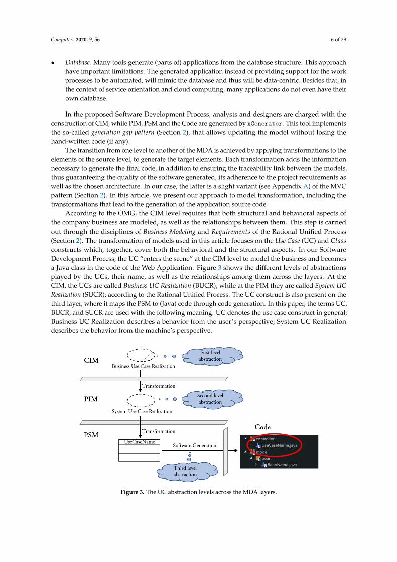
According to the OMG, the CIM level requires that both structural and behavioral aspects ofthe company business are modeled, as well as the relationships between them. This step is carriedout through the disciplines of Business Modeling and Requirements of the Rational Unified Process(Section 2). The transformation of models used in this article focuses on the Use Case (UC) and Classconstructs which, together, cover both the behavioral and the structural aspects. In our SoftwareDevelopment Process, the UC “enters the scene” at the CIM level to model the business and becomesa Java class in the code of the Web Application. Figure 3 shows the different levels of abstractionsplayed by the UCs, their name, as well as the relationships among them across the layers. At theCIM, the UCs are called Business UC Realization (BUCR), while at the PIM they are called System UCRealization (SUCR); according to the Rational Unified Process. The UC construct is also present on thethird layer, where it maps the PSM to (Java) code through code generation. In this paper, the terms UC,BUCR, and SUCR are used with the following meaning. UC denotes the use case construct in general;Business UC Realization describes a behavior from the user’s perspective; System UC Realizationdescribes the behavior from the machine’s perspective.
Figure 3. The UC abstraction levels across the MDA layers.

Computers 2020, 9, 56 7 of 29
3.2. Description of the Software Development Process
3.2.1. Computational Indepedent Model (CIM)
At the CIM level are discovered and modeled Business Actors, Business UC Realizations, BusinessObjects and Business Scenarios, according to the Rational Unified Process. A Business UC Realization isa sequence of actions defining the interactions between a Business Object and a (software) system toachieve a goal. Business Objects represent real world business entities at a higher level of abstractionthan software objects. Business Objects model organizational concepts, such as resources and BusinessActors. Each Business Actor performs a set of Business UC Realizations in the enterprise context.Each Business UC Realization captures an elementary aspect of the system. For every Business UCRealization the main scenario is described; all deviations to such a scenario are described as alternativescenarios. Next to the Business UC Realizations, that capture the desired behavior, the Business Objectsmodel provides a structural view of the software system. Business scenarios model the interactionbetween the behavioral and the structural aspects: each scenario is modeled with Sequence diagramsthat contain the Business Actors, the Boundary classes and the Business Objects.
The description of the Requirements completes the CIM. They concern the structural andbehavioral Business Rules. The former rules are represented in the Business Object diagram, throughthe attributes of each Business Object and the relationships between them. The behavioral businessrules are represented, in part, in the Business Object diagram and, in part, in the sequence diagrams ofthe business scenarios. Figure 4 depicts the elements of the business domain that play a relevant roleat the CIM level.
The CIM’s artefacts to be produced are: the Business UC Realization Diagram, the Business ObjectDiagrams, and the Sequence Diagrams of the Business scenarios.
Figure 4. The UML constructs and the Rules at the CIM.
3.2.2. Platform Independent Model (PIM)
At this level, the CIM models and the relationships among them are to be transformed into systemmodels by applying meta-models. A simplified version of the meta-models of Business Objects, UCsand Boundary classes is given in the next sub-section. The automatic transformation takes placeas follows:
1. analysis of the Business Actors, Business Objects and Business UC Realizations that participate inthe automation process (they are the only ones having a Boolean tag set to True), so they have tobe included in the system model;
2. trans f ormation of the Business Objects into Domain Classes;3. trans f ormation of the Business Actors into System Actors;4. trans f ormation of the Business UC Realizations whose tag is true, in as many System
UC Realizations;

Computers 2020, 9, 56 8 of 29
5. trans f ormation of the business scenario (modeled as Sequence diagrams) into a system scenario(modeled as Sequence diagrams): the Boundary classes (of the CIM) become View classes (at PIM).
The System UC Realization constitutes the basic element for the construction of the WebApplication. System UC Realizations handle a set of Business Objects for implementing operationssuch as: search, display, insert, edit, and so forth. The sequence diagram relates the structural aspect tothe behavioral one through the use of View and Domain classes, in the system perspective exactly ashappens in the business perspective. In addition to the mentioned transformations, in accordance withthe recommendations of MDA, at the PIM level it is necessary to add software system classes for theautomation, maintaining independence from the platform that will be chosen. In particular, this occursfor the management of the classes of Actors implemented in an additional component of xGenerator(the Login Component). Figure 5 depicts the elements of the system domain that play a relevant role atthe PIM level.
The PIM’s artefacts to be produced are: the System UC Realization Diagram, the Domain ClassDiagrams, and the Sequence Diagrams.
Figure 5. The UML constructs for the PIM.
3.2.3. The Platform Specific Model (PSM)
The same scenarios part of the PIM are still present at this level, but the Sequence Diagrams thatmodel them are more detailed, in fact, they contain the classes of all the architectural layers of theextended MVC pattern (see Appendix A). xGenerator transforms the analysis model of the PIM intoa design model using the meta-models illustrated in the next sub-section. The classes of each layerof the MVC pattern inherit from the corresponding classes of the meta-model. The automatic PIM toPSM transformation occurs as follows:
• about the structural aspect:
1. transformation of each Domain Class into a Bean class;2. transformation of the View classes of search present in the scenarios of the System UC
Realizations into a QueryContainer class;

Computers 2020, 9, 56 9 of 29
• about the behavioral aspect:
1. transformation of the System UC Realizations into UseCase classes;
• about the Graphical User Interface:
1. transformation of the View classes into UseCasePanel classes;2. transformation of the Views of editing present in the scenarios of the System UC Realizations
into ViewBeanInfo classes;3. creation of a ViewQueryInfo class for each QueryContainer class.
Figure 6 depicts the classes of the system domain at the PSM level. A class diagram correspondsto each MVC’s architectural layer.
The artefacts of the PSM are: the Use Case Class Diagrams, the Bean Class Diagrams, and theDetailed Sequence Diagrams.
Figure 6. The UML classes at the PSM.
3.2.4. The Code Model (PSM to Code)
Once the design of the PSM artefacts is completed, xGenerator generates the source code of theWeb Application and the deployment unit. It is possible to request either the generation of the code ofa Java project in the Eclipse environment or to invoke the generation of the code and the deployableunit on the cloud. As mentioned, the code is generated according to the specifications of the extendedMVC software architecture (Appendix A). In accordance with what is proposed in Reference [24],the classes are generated at two different levels of abstraction (Figure 7): for each class of the PSM,the superclass and the subclass are generated.
The output of the Code model are the artefacts: (a) one Java class for each class of the PSM at eacharchitectural layer; (b) a Java superclass for each class of the PSM at each architectural layer and asubclass that inherits from the superclass.

Computers 2020, 9, 56 10 of 29
Figure 7. The Java classes of the Web application.
Figure 8 summarizes our approach, by showing the artefacts produced at the variousMDA’s levels.
Figure 8. Overview of the proposed MDA transformational approach.
3.3. Our Meta-Models
To link the business perspective to the system perspective, we have defined meta-models forthe UML constructs class and UC. Figure 9 shows the main elements of the UML meta-model of thediagram of the Business Objects. Moving from the business perspective (CIM) to that of the softwaresystem, each Business Object becomes a Java Bean class that inherits from AbstractBusinessObject

Computers 2020, 9, 56 11 of 29
all the attributes and methods necessary to implement the standard behavior of a Business Object,including the management of its persistence in the database.
Figure 9. The UML meta-model of the Domain Class.
Figure 10 shows a simplified version of the meta-model of the UC construct. Moving from thebusiness perspective to the software system perspective, the UC becomes a Java class that inheritsfrom the AbstractUseCase class all the attributes and methods necessary to implement the standardbehavior of the UC.
Figure 10. The UML meta-model of the Use Case.
At a business level, the UC manipulates Boundary classes and Business Objects. At the systemlevel (PIM), the UC manipulates, respectively, Bean classes (Figure 11a) and Graphical User Interfaces(Figure 11b). In the context of the Web Applications, we use Panels as Graphical User Interfaces.
Figure 11. The UML meta-model of the Panel Class: (a) Bean classes; (b) Graphical User Interfaces.
Moving from the business perspective to the software system perspective, Boundary becomesa Panel class that inherits the attributes and methods necessary to implement the standardbehavior of a Graphical User Interface from AbstractUseCasePanel. AbstractUseCase uses theAbstractBusinessObject and the AbstractUseCasePanel to redirect the HTML pages to the browserand implement the expected UC behavior.
Computers 2020, 9, 56 12 of 29
3.4. Discussion
Model-driven code generation could be done given some minimal settings. First, you haveto know how to model; which modeling techniques to use, and how to use them. Our SoftwareDevelopment Process, uses UML and combines UCs and Class diagrams. Second, it is necessary to seta reference software architecture in order to generate a good and maintainable software. We adopt avariant of the MVC pattern. Third, to speed up the development further, it is recommended to usestandard tools. We adopt xGenerator which incorporates Vaadin and Hibernate.
The automatic translation of UML diagrams to object oriented code is highly desirable because iteliminates human errors in the translation process. As further merits of code generators, it is worthrecalling that they increase productivity, assure uniform code quality and respect of coding conventionsfor all the generated classes making part of a project, unlike handwritten code where the outcome is notalways predictable since it is programmer dependent. Code generators assume the role of writing hugevolume of repetitive code, which would take much longer if coded manually, leaving to programmersmore time to concentrate on the writing of specific portions of the whole application.
4. Case Study: The Automated Teller Machine (ATM) Project
This section applies the approach of Section 3 for developing a Web application named ATMProjectthat adheres to the extended MVC pattern of Appendix A. The application automates the bankingsubsystem for the management of withdrawals from an account, carried out through an ATM.A similar example is taken into account in References [2,25,26]. The application implements thefollowing operations: (a) withdrawal of a sum of money; (b) display of the balance; (c) display of thetransaction list.
The Web application has a single user profile (Customer) with specific privileges. Customer is aperson who owns a bank account. He is authorized to use the services provided by the bank throughan ATM card and a PIN. For the sake of simplicity, the management of the information about the ATMsand the Customers’ account are kept out of the case study. The business vocabulary (i.e., the generalconcepts) in our example is composed of: Customer, Bank Account, Transaction, Currency, and ATM;while the business rules to be implemented are the following: (a) a customer can activate N bankaccounts; (b) an account is owned by 1 customer; (c) N transactions can be made on an account; (d) atransaction takes place at an ATM; (e) a transaction has 1 currency.
The UML modeling of the ATM Project has been carried out with StarUML (http://staruml.io/).Following the best practices of the Rational Unified Process, the modeling file is organized in fourviews (Figure 12). The Use Case View is split in two packages: the Business Use-Case Model andthe System Use-Case Model (Figure 12b). The Logical View is split in two packages: the BusinessObject Model and the Design Model (Figure 12b). The Component View and the Deployment Viewwill not be used in the StarUML project file, because the code will be generated by xGenerator; thelatter imports the XMI file from the UML model of the ATM Project.

Computers 2020, 9, 56 13 of 29
Figure 12. (a) The four modeling views of the ATMProject; (b) the packages of the Use Case View andLogical View at the first level of nesting; (c) the packages of the Use Case View and Logical View atthe second level of nesting.
With regard to the Software Development Process of Section 3:
• the artefacts of the CIM are placed into the packages Business Use-Case Model and BusinessObjet Model (Figure 12c) and in the package View Model of the latter;
• the artefacts of the PIM are placed into the packages Actors and Use Cases internal to the packageSystem Use-Case Model and in the packages Layer and Use-Case Realizations of the packageDesign Model (Figure 12c);
• the artefacts of the PSM are placed into the packages Layer and Use-Case Realizations of thepackage Design Model. The package Layer contains the packages to model the classes of theextended MVC pattern (Appendix A).
4.1. CIM
Figure 13 shows the Withdraw Business UC Realization diagram. In it, Customer is a BusinessObject, but in the ATM subsystem it is also a Business Actor because it plays an active role. Therefore,Customer takes the stereotype «Business Worker».
Figure 13. The diagram of the Withdraw Business UC Realization.
Figure 14 lists the names of the business scenarios of the Withdraw Business UC Realization:Select Operation (it is the basic scenario) and Withdraw, Account Balance, and Transaction List(they are the alternative scenarios that correspond to the three options shown to the customer at anATM).
Figure 14. The names of the business scenarios of the Withdraw Business UC Realization.

Computers 2020, 9, 56 14 of 29
Figures 15–18 show, respectively, the sequence diagram of the business scenarios SelectOperation, Withdraw, Account Balance, and Transaction List of the Withdraw BusinessUC Realization.
Figure 15. The sequence diagram of the business scenario Select Operation.
Figure 16. The sequence diagrams of the business scenario Withdraw.
Figure 17. The sequence diagrams of the business scenario Account Balance.

Computers 2020, 9, 56 15 of 29
Figure 18. The sequence diagrams of the business scenario Transaction List.
Figure 19 lists the names of the Boundary classes of the Withdraw Business UC Realization.
Figure 19. The names of the boundary classes of the Withdraw Business UC Realization.
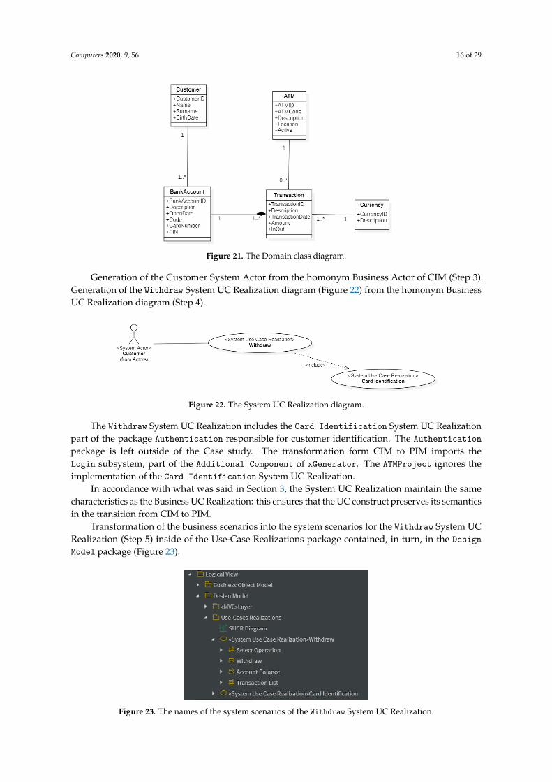
Figure 20 shows the diagram of the Business Objects: Customer, ATM, BankAccount,Transaction, and Currency. Their name is self-explanatory. Figure 20 shows, moreover,the implementation of the business rules through the min..max constraints between pairs ofBusiness Objects.
Figure 20. The diagram of the Business Objects.
4.2. PIM
The artefacts generated by xGenerator to map CIM to PIM are described below. They implementthe Steps 1–5 of the PIM (Section 3.2). The Business Actors, Business Objects and the Business UCRealization of the CIM must be automated (Tag=True) (Step 1). Generation of the Domain classes fromthe Business Objects (Figure 21) (Step 2). In each Domain class are present all the attributes of thecorresponding Business Object besides the IDentifier field.
Computers 2020, 9, 56 16 of 29
Figure 21. The Domain class diagram.
Generation of the Customer System Actor from the homonym Business Actor of CIM (Step 3).Generation of the Withdraw System UC Realization diagram (Figure 22) from the homonym BusinessUC Realization diagram (Step 4).
Figure 22. The System UC Realization diagram.
The Withdraw System UC Realization includes the Card Identification System UC Realizationpart of the package Authentication responsible for customer identification. The Authenticationpackage is left outside of the Case study. The transformation form CIM to PIM imports theLogin subsystem, part of the Additional Component of xGenerator. The ATMProject ignores theimplementation of the Card Identification System UC Realization.
In accordance with what was said in Section 3, the System UC Realization maintain the samecharacteristics as the Business UC Realization: this ensures that the UC construct preserves its semanticsin the transition from CIM to PIM.
Transformation of the business scenarios into the system scenarios for the Withdraw System UCRealization (Step 5) inside of the Use-Case Realizations package contained, in turn, in the DesignModel package (Figure 23).
Figure 23. The names of the system scenarios of the Withdraw System UC Realization.

Computers 2020, 9, 56 17 of 29
Figures 24–27 show, respectively, the sequence diagram of the system scenarios SelectOperation, Withdraw, Account Balance, and Transaction List of the Withdraw SystemUC Realization. The name of each View class is a string composed as follows:UseCasePanel+SUCRName+BoundaryClassName; when BoundaryClassName is identical to SUCRName therepetition is omitted.
Figure 24. The sequence diagram of the system scenario Select Operation.
Figure 25. The sequence diagrams of the system scenario Withdraw.
Figure 26. The sequence diagrams of the system scenario Account Balance.

Computers 2020, 9, 56 18 of 29
Figure 27. The sequence diagrams of the system scenario Transaction List.
4.3. PSM
The following describes the artifacts generated by xGenerator to go from PIM to PSM (Section 3.2).Figure 28 shows the MVC layers of the source code to be generated.
Figure 28. The architectural layers of the source code to be generated.
The Bean classes (Step 1, Structural aspect) and UseCase classes (Step 1, Behavioral aspect)are shown in Figure 29a and Figure 29b, respectively; Figure 29c shows the View layer and theUseCaseWithdraw package containing the panels (Figure 30c) of the Withdraw UC (Step 1, about theGraphical User Interface).
Figure 29. The architectural layers at PSM: (a) the Bean classes; (b) the UseCase classes; (c) the Viewlayer.
The execution of Step 2 (Structural aspect) and Steps 2 and 3 (about the Graphical User Interface)generate the classes of the remaining architectural layers (Figure 30a,b).
Figure 30. The detailed architectural layers at PSM: (a) the QueryContainer classes; (b) theViewBeanInfo classes; (c) the panels of the Withdraw UC.
Each class of the architectural layers extends the corresponding Abstract class of the meta-model.Figure 31a–d show, in order, the diagrams of the classes relative to the Withdraw System UC Realization

Computers 2020, 9, 56 19 of 29
for the classes Model Bean, Model QueryContainer, Controller, ViewQueryContainer and the Panelof the Withdraw package (Figure 31e).
Figure 31. The class diagrams for the Withdraw System UC Realization: (a) Model Beanclasses; (b) Model QueryContainer classes; (c) Controller classes; (d) ViewQueryContainer classes;(e) Panel classes.
4.4. The Code
xGenerator generates the code and the deployable unit (if required). Figure 32 shows the WebGraphical User Interface that corresponds to the Withdraw System UC Realization.
Figure 32. The Graphical User Interface that matches the Withdraw System UC Realization (left).An example of withdrawal (right).
Notice that, the structure of the Eclipse ATMProject (Figure 33) is specular to that of the designlayers (Figure 28).

Computers 2020, 9, 56 20 of 29
Figure 33. The Eclipse’s packages of the Java ATMProject.
Figure 34 shows a portion of Java code of the UseCasePanelWithdraw.java class that displaysthe Withdraw panel of Figure 32.
Figure 34. Code of the UseCasePanelWithdraw.java class.
Table 1 shows the numbers about the ATMProject. The number of Nested Classes are not mentionedin Table 1. According to the generation gap pattern (Section 2), the code comprises 12 superclasses and12 subclasses. The generated subclasses (namely: BankAccount, Transaction, Currancy and ATM) areempty, therefore they do not add methods, while they add 3 extra lines of code per class.
Table 1. Numbers about the ATMProject.
Use Case Number of Classes Number of Methods Lines of Code
Withdraw 12 70 982
Computers 2020, 9, 56 21 of 29
5. Related Work
This section starts with an overview about code generation in the MDE domain, then it turns tothe code generation in the MDA domain, eventually it provides a closer look to a recently appearedpaper that is very close to ours.
5.1. Code Generation within MDE
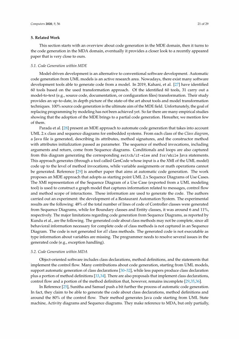
Model-driven development is an alternative to conventional software development. Automaticcode generation from UML models is an active research area. Nowadays, there exist many softwaredevelopment tools able to generate code from a model. In 2019, Kahani, et al. [27] have identified60 tools based on the used transformation approach. Of the identified 60 tools, 31 carry out amodel-to-text (e.g., source code, documentation, or configuration files) transformation. Their studyprovides an up-to-date, in depth picture of the state-of-the art about tools and model transformationtechniques. 100% source code generation is the ultimate aim of the MDE field. Unfortunately, the goal ofreplacing programming by modeling has not been achieved yet. So far there are many empirical studiesshowing that the adoption of the MDE brings to a partial code generation. Hereafter, we mention fewof them.
Parada et al. [28] present an MDE approach to automate code generation that takes into accountUML 2.x class and sequence diagrams for embedded systems. From each class of the Class diagram,a Java file is generated, describing its attributes, method signatures, and the constructor methodwith attributes initialization passed as parameter. The sequence of method invocations, includingarguments and return, come from Sequence diagrams. Conditionals and loops are also capturedfrom this diagram generating the corresponding switch/if-else and for/while Java statements.This approach generates (through a tool called GenCode whose input is a the XMI of the UML model)code up to the level of method invocations, while variable assignments or math operations cannotbe generated. Reference [29] is another paper that aims at automatic code generation. The workproposes an MDE approach that adopts as starting point UML 2.x Sequence Diagrams of Use Cases.The XMI representation of the Sequence Diagram of a Use Case (exported from a UML modelingtool) is used to construct a graph model that captures information related to messages, control flowand method scope of interactions. These information are used to generate the code. The authorscarried out an experiment: the development of a Restaurant Automation System. The experimentalresults are the following: 48% of the total number of lines of code of Controller classes were generatedfrom Sequence Diagrams, while for Boundary classes and Entity classes, it was around 6 and 11%,respectively. The major limitations regarding code generation from Sequence Diagrams, as reported byKundu et al., are the following. The generated code about class methods may not be complete, since allbehavioral information necessary for complete code of class methods is not captured in an SequenceDiagram. The code is not generated for all class methods. The generated code is not executable astype information about variables are missing. The programmer needs to resolve several issues in thegenerated code (e.g., exception handling).
5.2. Code Generation within MDA
Object-oriented software includes class declarations, method definitions, and the statements thatimplement the control flow. Many contributions about code generation, starting from UML models,support automatic generation of class declarations [30–32], while less papers produce class declarationplus a portion of method definitions [33,34]. There are also proposals that implement class declarations,control flow and a portion of the method definition that, however, remains incomplete [29,35,36].
In Reference [25], Sunitha and Samuel push a bit further the process of automatic code generation.In fact, they claim to be able to generate the code about class declarations, method definitions andaround the 80% of the control flow. Their method generates Java code starting from UML Statemachine, Activity diagrams and Sequence diagrams. They make reference to MDA, but only partially,

Computers 2020, 9, 56 22 of 29
in fact the behavioral modeling starts at the PIM level. During code generation, each Activity diagramis converted to a class while each node in the activity diagram gives rise to a function call in the main()of the class. The interface of methods inside a class comes from a message inside a specific Sequencediagram. The body of methods is filled out by taking into account the State machines, while theiractual parameters come from OCL expressions (Object Constraint Language is an OMG standard [37]).The transformation rules for converting the XMI file to Java is written in XSLT.
5.3. Comparison with an MDA Approach for Web Application Development
Reference [18] reports on the state-of-the-art of code generation using MDA research insoftware engineering. The authors identified 50 primary studies out of 2.145 related MDA articlesover the period 2008–2018. From this study comes out that the five main areas of interest are:“mobile application development, simulation and verification, security, Web engineering and GUIdevelopment”. Our paper belongs to Web engineering. Moreover, the authors have reached 50 relevantpublications using MDA arriving at the generation of code (executable or not) automatically. The surveyreports that most studied approaches employ PIMs and PSMs only, avoiding the inclusion of CIMs inthe model architecture. Our Software Development Process starts at the CIM layer.
In Reference [38], the authors apply MDA to develop MVC Web Applications. Their proposalcombines UML class and sequence diagrams to constitute one source meta-model of the transformationlanguage. They use ATL (Atlas Transformation Language) as transformation language. The proposedmethod ignores the CIM level. The method is applied to a case study concerning a PC online shopping.The authors claim that the generated code has reached about 85% of total code. In References [39,40],the authors present an MDA-based approach that allows the implementation of Graphical UserInterface for Rich Internet Applications with JavaFX platform as a target, respecting the MVC pattern.The proposed method starts at the PIM level.
The research by Essebaa, Chantit and Ramdani [41] constitutes a very recent testimony ofapplication of MDA to Web applications. Their work describes a tool (MoDAr-WA) aiming to automatetransformations from CIM to code. Authors use QVT rules for transformations between models (CIM toPIM and PIM to PSM) and Acceleo for generating the code that respects the MVC architecture from PSMmodels. The authors compare their proposal with a large number of related works. The conclusion wasthat their solution is the unique one that besides covering CIM and PIM aspects, provide transformationrules between CIM and PIM, automate them and allow their traceability. Because of this claim,we conclude the section by comparing our work with that of Reference [41].
Figures 8 and 35 depict the differences between our and their approach, at the various levels ofMDA. Below, we discuss the three relevant differences between the two approaches.
Figure 35. Overview of the approach in Reference [41].
Computers 2020, 9, 56 23 of 29
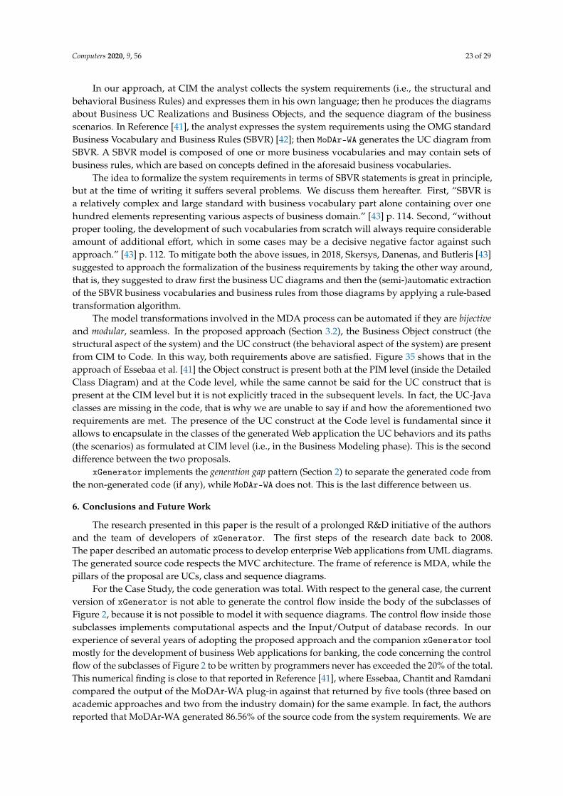
In our approach, at CIM the analyst collects the system requirements (i.e., the structural andbehavioral Business Rules) and expresses them in his own language; then he produces the diagramsabout Business UC Realizations and Business Objects, and the sequence diagram of the businessscenarios. In Reference [41], the analyst expresses the system requirements using the OMG standardBusiness Vocabulary and Business Rules (SBVR) [42]; then MoDAr-WA generates the UC diagram fromSBVR. A SBVR model is composed of one or more business vocabularies and may contain sets ofbusiness rules, which are based on concepts defined in the aforesaid business vocabularies.
The idea to formalize the system requirements in terms of SBVR statements is great in principle,but at the time of writing it suffers several problems. We discuss them hereafter. First, “SBVR isa relatively complex and large standard with business vocabulary part alone containing over onehundred elements representing various aspects of business domain.” [43] p. 114. Second, “withoutproper tooling, the development of such vocabularies from scratch will always require considerableamount of additional effort, which in some cases may be a decisive negative factor against suchapproach.” [43] p. 112. To mitigate both the above issues, in 2018, Skersys, Danenas, and Butleris [43]suggested to approach the formalization of the business requirements by taking the other way around,that is, they suggested to draw first the business UC diagrams and then the (semi-)automatic extractionof the SBVR business vocabularies and business rules from those diagrams by applying a rule-basedtransformation algorithm.
The model transformations involved in the MDA process can be automated if they are bijectiveand modular, seamless. In the proposed approach (Section 3.2), the Business Object construct (thestructural aspect of the system) and the UC construct (the behavioral aspect of the system) are presentfrom CIM to Code. In this way, both requirements above are satisfied. Figure 35 shows that in theapproach of Essebaa et al. [41] the Object construct is present both at the PIM level (inside the DetailedClass Diagram) and at the Code level, while the same cannot be said for the UC construct that ispresent at the CIM level but it is not explicitly traced in the subsequent levels. In fact, the UC-Javaclasses are missing in the code, that is why we are unable to say if and how the aforementioned tworequirements are met. The presence of the UC construct at the Code level is fundamental since itallows to encapsulate in the classes of the generated Web application the UC behaviors and its paths(the scenarios) as formulated at CIM level (i.e., in the Business Modeling phase). This is the seconddifference between the two proposals.
xGenerator implements the generation gap pattern (Section 2) to separate the generated code fromthe non-generated code (if any), while MoDAr-WA does not. This is the last difference between us.
6. Conclusions and Future Work
The research presented in this paper is the result of a prolonged R&D initiative of the authorsand the team of developers of xGenerator. The first steps of the research date back to 2008.The paper described an automatic process to develop enterprise Web applications from UML diagrams.The generated source code respects the MVC architecture. The frame of reference is MDA, while thepillars of the proposal are UCs, class and sequence diagrams.
For the Case Study, the code generation was total. With respect to the general case, the currentversion of xGenerator is not able to generate the control flow inside the body of the subclasses ofFigure 2, because it is not possible to model it with sequence diagrams. The control flow inside thosesubclasses implements computational aspects and the Input/Output of database records. In ourexperience of several years of adopting the proposed approach and the companion xGenerator toolmostly for the development of business Web applications for banking, the code concerning the controlflow of the subclasses of Figure 2 to be written by programmers never has exceeded the 20% of the total.This numerical finding is close to that reported in Reference [41], where Essebaa, Chantit and Ramdanicompared the output of the MoDAr-WA plug-in against that returned by five tools (three based onacademic approaches and two from the industry domain) for the same example. In fact, the authorsreported that MoDAr-WA generated 86.56% of the source code from the system requirements. We are

Computers 2020, 9, 56 24 of 29
working on an extension of the xGenerator which introduces two important improvements to thecurrent version. The first involves modeling the control flow by means of UML diagrams. The secondimprovement concerns the introduction of a set of UML domain stereotypes and constraints, to realizea lightweight extension to the UML using the profiling approach introduced by OMG [2]. UML is ageneral purpose modeling language. Stereotypes were introduced for customizing UML in order tobe tailored to specific application domains. Therefore, stereotypes are a mechanism to convert UMLinto a domain specific modelling language. This approach is extensively adopted, for instance, in thesecurity and privacy domains (e.g., References [44–46]). We are confident that by stereotyping theBusiness UCs will improve the enterprise software development process toward full code generation.
Our experience of several years of adopting the proposed approach and the companionxGenerator tool goes in countertrend if compared with the findings of many scholars which havereported that the adoption in industry of the MDE approach is far from successful (Section 1). We canassert that moving from the standard Object-Oriented programming paradigm to the model-basedparadigm made Software Industriale (an Italian small software company, structured as a network offour branches located in different regions of the Country—https://www.softwareindustriale.it/) morecompetitive. Model Driven Engineering (MDE) has emerged as a new software engineering disciplinewhich emphasizes both software productivity and software quality, besides a easier communicationwith our clients carried out at the business modeling level. When new developers are hired for aproject, before they are aggregated to the core development team, they receive an internal trainingabout MDE, MDA and the xGenerator tool for one working week. The research team of SoftwareIndustriale is in charge of the training. This action implements one of the three best practices suggestedin Reference [12], for MDE to be successful.
Future research and development directions will be aimed at extending the proposed SoftwareDevelopment Process to domains different from enterprise Web applications. The first domain ofour interest concerns the Mechatronics. The development of mechatronic systems involves the use ofdisciplines from mechanical engineering, electronics engineering and computer science. Traditionally,every discipline was developed independently and then integrated to generate the final system.This approach is criticized as inappropriate for the complexity and the dynamics of today’s systems(see, for instance, Reference [47]). High-quality designs cannot be achieved without simultaneouslyconsidering all the engineering disciplines. The complexity of the automation of the softwareembedded into mechatronic systems is rising since the proportion of system functionality that isrealized by software is increasing, too. Therefore, the modeling approach seems to be particularlysuitable for handling the software complexity. At present, we are investigating the formalizationof a minimal set of ad-hoc UML profiles to deal with the complexities of the mechatronics domain.The survey by Wortmann et al. [48] is an up-to-date source about the role of UML in the Industry 4.0.
With the diffusion of smartphones equipped with GPS, WiFi and various sensors, monitoringthe position of people and relevant goods is technically possible today (e.g., References [49,50]).The difficult task is the development of the source code of Web applications accessing such big data.We plan to extend our approach and, hence, the xGenerator to this domain.
Author Contributions: Conceptualization, G.P. and P.D.F.; Methodology, G.P.; Case study, M.M.; Software, R.P.;Validation, M.M. and R.P.; Formal analysis, P.D.F.; Writing, P.D.F.; Funding acquisition, G.P. All authors have readand agreed to the published version of the manuscript.
Funding: This research was funded by Software Industriale.
Conflicts of Interest: The authors declare no conflict of interest.
Computers 2020, 9, 56 25 of 29
Abbreviations
The following abbreviations are used in this manuscript:
BCD Business Class DiagramBUCR Business UC RealizationCIM Computation Independent ModelHTML HyperText Markup LanguageMDA Model Driven ArchitectureMDE Model Driven EngineeringMVC Model-View-ControllerOMG Object Management GroupPIM Platform Independent ModelPSM Platform Specific ModelQVT Query View TransformationSBVR Semantic Business Vocabulary and Business RulesSUCR System UC RealizationUML Unified Modeling LanguageUC Use CaseUCD Use Case Diagram
Appendix A. xGenerator
xGenerator is a Java technology platform for the development of enterprise Web applications. At ahigh level of abstraction, xGenerator is a black box that receives as input an UML model and returnsthe Java code of the Web application. The basic guidelines underlying the design and implementationof the xGenerator are the following:
• the business model is “pure”, in the sense that it is not contaminated by information about layersdifferent from the business one. A pure model is composed of business objects without anyreference to features related to the data sources (i.e., databases, XML files, and Web Services) or tothe interface (i.e., textBox, Form, checkBox);
• the notion of use case acts as a link between the analysis model and the coding of thebehavioral aspect.
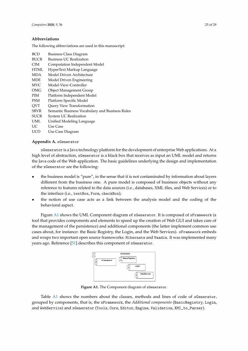
Figure A1 shows the UML Component diagram of xGenerator. It is composed of xFramework (atool that provides components and elements to speed up the creation of Web GUI and takes care ofthe management of the persistence) and additional components (the latter implement common usecases about, for instance: the Basic Registry, the Login, and the Web Services). xFramework embedsand wraps two important open source frameworks: Hibernate and Vaadin. It was implemented manyyears ago. Reference [51] describes this component of xGenerator.
Figure A1. The Component diagram of xGenerator.
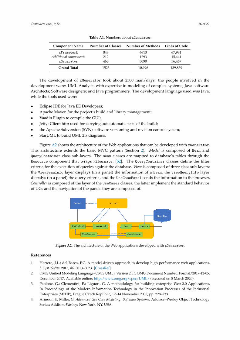
Table A1 shows the numbers about the classes, methods and lines of code of xGenerator,grouped by components, that is, the xFramework, the Additional components (BasicRegistry, Login,and WebService) and xGenerator (Tools, Core, Editor, Engine, Validation, XMI_to_Parser).
Computers 2020, 9, 56 26 of 29
Table A1. Numbers about xGenerator
Component Name Number of Classes Number of Methods Lines of Code
xFramework 843 6613 67,931Additional components 212 1293 15,441
xGenerator 468 3090 56,467
Grand Total 1523 10,996 139,839
The development of xGenerator took about 2500 man/days; the people involved in thedevelopment were: UML Analysts with expertise in modeling of complex systems; Java softwareArchitects; Software designers; and Java programmers. The development language used was Java,while the tools used were:
• Eclipse IDE for Java EE Developers;• Apache Maven for the project’s build and library management;• Vaadin Plugin to compile the GUI;• Jetty: Client http used for carrying out automatic tests of the build;• the Apache Subversion (SVN) software versioning and revision control system;• StarUML to build UML 2.x diagrams.
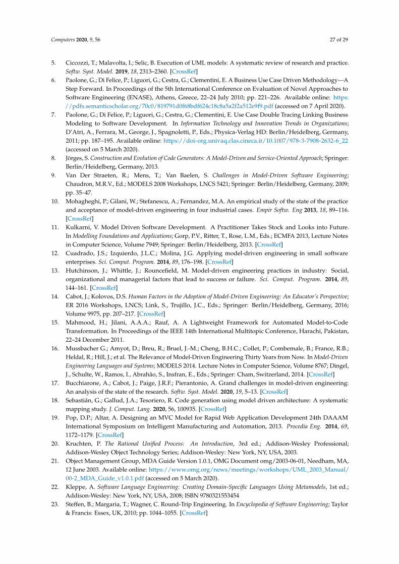
Figure A2 shows the architecture of the Web applications that can be developed with xGenerator.This architecture extends the basic MVC pattern (Section 2). Model is composed of Bean andQueryContainer class sub-layers. The Bean classes are mapped to database’s tables through theResource component that wraps Hibernate, [52]. The QueryContainer classes define the filtercriteria for the execution of queries against the database. View is composed of three class sub-layers:the ViewBeanInfo layer displays (in a panel) the information of a Bean, the ViewQueryInfo layerdispalys (in a panel) the query criteria, and the UseCasePanel sends the information to the browser.Controller is composed of the layer of the UseCases classes; the latter implement the standard behaviorof UCs and the navigation of the panels they are composed of.
Figure A2. The architecture of the Web applications developed with xGenerator.
References
1. Herrero, J.L.; del Barco, P.C. A model-driven approach to develop high performance web applications.J. Syst. Softw. 2013, 86, 3013–3023. [CrossRef]
2. OMG Unified Modeling Language (OMG UML), Version 2.5.1 OMG Document Number: Formal/2017-12-05,December 2017. Available online: https/www.omg.org/spec/UML/ (accessed on 5 March 2020).
3. Paolone, G.; Clementini, E.; Liguori, G. A methodology for building enterprise Web 2.0 Applications.In Proceedings of the Modern Information Technology in the Innovation Processes of the IndustrialEnterprises (MITIP), Prague Czech Republic, 12–14 November 2008; pp. 228–233.
4. Armour, F.; Miller, G. Advanced Use Case Modeling: Software Systems; Addison-Wesley Object TechnologySeries; Addison-Wesley: New York, NY, USA.
Computers 2020, 9, 56 27 of 29
5. Ciccozzi, T.; Malavolta, I.; Selic, B. Execution of UML models: A systematic review of research and practice.Softw. Syst. Model. 2019, 18, 2313–2360. [CrossRef]
6. Paolone, G.; Di Felice, P.; Liguori, G.; Cestra, G.; Clementini, E. A Business Use Case Driven Methodology—AStep Forward. In Proceedings of the 5th International Conference on Evaluation of Novel Approaches toSoftware Engineering (ENASE), Athens, Greece, 22–24 July 2010; pp. 221–226. Available online: https://pdfs.semanticscholar.org/70c0/819791d0f68bdf624c18c8a5a2f2a512e9f9.pdf (accessed on 7 April 2020).
7. Paolone, G.; Di Felice, P.; Liguori, G.; Cestra, G.; Clementini, E. Use Case Double Tracing Linking BusinessModeling to Software Development. In Information Technology and Innovation Trends in Organizations;D’Atri, A., Ferrara, M., George, J., Spagnoletti, P., Eds.; Physica-Verlag HD: Berlin/Heidelberg, Germany,2011; pp. 187–195. Available online: https://doi-org.univaq.clas.cineca.it/10.1007/978-3-7908-2632-6_22(accessed on 5 March 2020).
8. Jörges, S. Construction and Evolution of Code Generators: A Model-Driven and Service-Oriented Approach; Springer:Berlin/Heidelberg, Germany, 2013.
9. Van Der Straeten, R.; Mens, T.; Van Baelen, S. Challenges in Model-Driven Software Engineering;Chaudron, M.R.V., Ed.; MODELS 2008 Workshops, LNCS 5421; Springer: Berlin/Heidelberg, Germany, 2009;pp. 35–47.
10. Mohagheghi, P.; Gilani, W.; Stefanescu, A.; Fernandez, M.A. An empirical study of the state of the practiceand acceptance of model-driven engineering in four industrial cases. Empir Softw. Eng 2013, 18, 89–116.[CrossRef]
11. Kulkarni, V. Model Driven Software Development. A Practitioner Takes Stock and Looks into Future.In Modelling Foundations and Applications; Gorp, P.V., Ritter, T., Rose, L.M., Eds.; ECMFA 2013, Lecture Notesin Computer Science, Volume 7949; Springer: Berlin/Heidelberg, 2013. [CrossRef]
12. Cuadrado, J.S.; Izquierdo, J.L.C.; Molina, J.G. Applying model-driven engineering in small softwareenterprises. Sci. Comput. Program. 2014, 89, 176–198. [CrossRef]
13. Hutchinson, J.; Whittle, J.; Rouncefield, M. Model-driven engineering practices in industry: Social,organizational and managerial factors that lead to success or failure. Sci. Comput. Program. 2014, 89,144–161. [CrossRef]
14. Cabot, J.; Kolovos, D.S. Human Factors in the Adoption of Model-Driven Engineering: An Educator’s Perspective;ER 2016 Workshops, LNCS; Link, S., Trujillo, J.C., Eds.; Springer: Berlin/Heidelberg, Germany, 2016;Volume 9975, pp. 207–217. [CrossRef]
15. Mahmood, H.; Jilani, A.A.A.; Rauf, A. A Lightweight Framework for Automated Model-to-CodeTransformation. In Proceedings of the IEEE 14th International Multitopic Conference, Harachi, Pakistan,22–24 December 2011.
16. Mussbacher G.; Amyot, D.; Breu, R.; Bruel, J.-M.; Cheng, B.H.C.; Collet, P.; Combemale, B.; France, R.B.;Heldal, R.; Hill, J.; et al. The Relevance of Model-Driven Engineering Thirty Years from Now. In Model-DrivenEngineering Languages and Systems; MODELS 2014. Lecture Notes in Computer Science, Volume 8767; Dingel,J., Schulte, W., Ramos, I., Abrahão, S., Insfran, E., Eds.; Springer: Cham, Switzerland, 2014. [CrossRef]
17. Bucchiarone, A.; Cabot, J.; Paige, J.R.F.; Pierantonio, A. Grand challenges in model-driven engineering:An analysis of the state of the research. Softw. Syst. Model. 2020, 19, 5–13. [CrossRef]
18. Sebastián, G.; Gallud, J.A.; Tesoriero, R. Code generation using model driven architecture: A systematicmapping study. J. Comput. Lang. 2020, 56, 100935. [CrossRef]
19. Pop, D.P.; Altar, A. Designing an MVC Model for Rapid Web Application Development 24th DAAAMInternational Symposium on Intelligent Manufacturing and Automation, 2013. Procedia Eng. 2014, 69,1172–1179. [CrossRef]
20. Kruchten, P. The Rational Unified Process: An Introduction, 3rd ed.; Addison-Wesley Professional;Addison-Wesley Object Technology Series; Addison-Wesley: New York, NY, USA, 2003.
21. Object Management Group, MDA Guide Version 1.0.1, OMG Document omg/2003-06-01, Needham, MA,12 June 2003. Available online: https://www.omg.org/news/meetings/workshops/UML_2003_Manual/00-2_MDA_Guide_v1.0.1.pdf (accessed on 5 March 2020).
22. Kleppe, A. Software Language Engineering: Creating Domain-Specific Languages Using Metamodels, 1st ed.;Addison-Wesley: New York, NY, USA, 2008; ISBN 9780321553454
23. Steffen, B.; Margaria, T.; Wagner, C. Round-Trip Engineering. In Encyclopedia of Software Engineering; Taylor& Francis: Essex, UK, 2010; pp. 1044–1055. [CrossRef]

Computers 2020, 9, 56 28 of 29
24. Vlissides, J.M. Pattern Hatching: Design Patterns Applied; Addison-Wesley: New York, NY, USA, 1998;ISBN 0201432935.
25. Sunitha, E.V.; Samuel, P. Translation of behavioral models to source code. In Proceedings of the 12thInternational Conference on Intelligent Systems Design and Applications (ISDA), Kochi, India, 27–29November 2012; pp. 598–604.
26. Sunitha, E.V.; Samuel, P. Object constraint language for code generation from activity models.Inf. Softw. Technol. 2018, 103, 92–111. [CrossRef]
27. Kahani, N.; Bagherzadeh, M.; Cordy, J.R.; Dingel, J.; Varró, D. Survey and classification of modeltransformation tools. Softw. Syst. Model. 2019, 18, 2361–2397. [CrossRef]
28. Parada, A.G.; Siegert, E.; de Brisolara, L.B. Generating Java code from UML Class and Sequence Diagrams.In Proceedings of the Brazilian Symposium on Computing System Engineering, Florianopolis, Brazil, 7–11November 2011; pp. 99–101. [CrossRef]
29. Kundu, D.; Samanta, D.; Mall, R. Automatic code generation from unified modelling language sequencediagrams. IET Softw. 2013, 7, 12–28. [CrossRef]
30. Bjoraa, E.; Myhre, T.; Straapa, E.W. Generating Java Skeleton from XMI. In Open Distributed Systems; AgderUniversity College: Kristiansand, Norway, 2000.
31. Harrison, W.; Barton, C.; Raghavachari, M. Mapping UML designs to Java. In Proceedings of the 15thACM SIGPLAN Conference on Object-Oriented Programming, Systems, Languages, and Applications,Minneapolis, MN, USA, 15–19, October 2000; pp. 178–187. [CrossRef]
32. Niaz, I.A. Automatic Code Generation from UML Class and Statechart Diagrams; Thesis Report; University ofTsukuba: Tsukuba, Japan, 2005.
33. Long, Q.; Liu, Z.; Li, X.; He, J. Consistent code generation from UML models. In Proceedings of the AustralianSoftware Engineering Conference, Brisbane, Australia, 29 March–1 April 2005.
34. Rudhal, K.T.; Goldin, S.E. Adaptive multi-language code generation using YAMDAT. In Proceedings ofthe ECTI-CON 2008, Electrical Engineering/Electronics, Computer, Telecommunications and InformationTechnology, Krabi, Thailand, 14–17 May 2008; Volume 1, pp. 181–184.
35. Yin, L.; Liu, J.; Ding, Z. Modeling and prototyping business processes in AutoPA. In Proceedings of theFifth International Symposium on Theoretical Aspects of Software Engineering (TASE), Xi’an, China, 29–31August 2011.
36. Usman, M.; Nadeem, A.; Kim, T.-H. UJECTOR: A tool for executable code generation from UML models.In Proceedings of the Conference on Advanced Software Engineering and Its Applications, Hainan Island,China, 13–15 December 2008.
37. OMG Object Constraint Language (OCL) Version 2.3.1, January 2012. OMG Document Number:Formal/2012-01-01. Standard Document. Available online: http://www.omg.org/spec/OCL/2.3.1(accessed on 9 March 2020).
38. Rahmouni, M.; Mbarki, S. Model-Driven Generation: From Models to MVC2 Web Applications. Int. J. Softw.Eng. Its Appl. 2014, 8, 73–94. [CrossRef]
39. Roubi, S.; Erramdani, M.; Mbarki, S. Modeling and generating graphical user interface for MVC richinternet application using a model driven approach. In Proceedings of the 2016 International Conference onInformation Technology for Organizations Development (IT4OD), Fez, Morocco, 30 March–1 April 2016;pp. 1–6 . [CrossRef]
40. Roubi, S.; Erramdani, M.; Mbarki, S. Model Driven Approach based on Interaction Flow Modeling Languageto Generate Rich Internet Applications. Int. J. Electr. Comput. Eng. IJECE 2016, 6, 3073–3079. [CrossRef]
41. Essebaa, I.; Chantit, S.; Ramdani, M. MoDAr-WA: Tool Support to Automate an MDA Approach for MVCWebApplication. Computers 2019, 8, 89. [CrossRef]
42. OMG. Semantics of Business Vocabulary and Business Rules (SBVR) v.1.5, OMG Doc. No. formal/2019-10-02[SMSC/19-10-02], October 2019. Available online: https://www.omg.org/spec/SBVR/1.5/Beta1/PDF(accessed on 15 March 2020).
43. Skersys, T.; Danenas, P.; Butleris, R. Extracting SBVR business vocabularies and business rules from UMLuse case diagrams. J. Syst. Softw. 2018, 141, 111–130. [CrossRef]
44. Mažeika, D.; Butleris, R. MBSEsec: Model-Based Systems Engineering Method for Creating Secure Systems.Appl. Sci. 2020, 10, 2574. [CrossRef]
Computers 2020, 9, 56 29 of 29
45. Mai, P.X.; Goknil, A.; Shar, L.K.; Pastore, F.; Briand, L.C.; Shaame, S. Modeling Security and PrivacyRequirements: A Use Case-Driven Approach. Inf. Softw. Technol. 2018, 100, 165–182. [CrossRef]
46. Jürjens, J. Model-Based Security Engineering with UML: Introducing Security Aspects. In Formal Methodsfor Components and Objects, Proceedings of the International Symposium on Formal Methods for Components andObjects (FMCO 2005), Amsterdam, The Netherlands, 1–4 November 2005; Lecture Notes in Computer Science,Volume 4111; De Boer, F.S., Bonsangue, M.M., Graf, S., de Roever, W.P., Eds.; Springer: Berlin/Heidelberg,Germany, 2005; pp. 64–87. [CrossRef]
47. Rzevski, G. On Conceptual Design of Intelligent Mechatronic Systems. Mechatronics 2003, 13, 1029–1044.[CrossRef]
48. Wortmann, A.; Barais, O.; Combemale, B.; Wimmer, M. Modeling languages in Industry 4.0: An extendedsystematic mapping study. Softw. Syst. Model. 2020, 19, 67–94. [CrossRef]
49. Aminuddin, M.A.I.M.; Osman, M.A.; Zainon, W.M.N.W.; Talib, A.Z. Location Tracking and LocationPrediction Techniques for Smart Traveler Apps. In Intelligent Systems and Applications: Proceedings of the 2019Intelligent Systems Conference (IntelliSys); Advances in Intelligent Systems and Computing, Volume 1037; Bi,Y., Bhatia, R., Kapoor, S., Eds.; Springer: Cham, Switzerland, 2020; pp. 83–96. [CrossRef]
50. Fernández-Ares, A.; Mora, A.M.; Arenas, M.G.; García-Sanchez, P. Studying real traffic and mobility scenariosfor a Smart City using a new monitoring and tracking system. Future Gener. Comput. Syst. 2017, 76, 163–179.[CrossRef]
51. Paolone, G.; Liguori, G.; Cestra, G.; Clementini, E. Web 2.0 Applications: Model-Driven Tools and Design.In Management of the Interconnected World; D’Atri, A., De Marco, M., Braccini, A., Cabiddu, F., Eds.;Physica-Verlag HD: Berlin/Heidelberg, Germany, 2010; pp. 343–350. [CrossRef]
52. Torres, A.; Galante, R.; Pimenta, M.S.; Martins, A.J.B. Twenty years of object-relational mapping: A surveyon patterns, solutions, and their implications on application design. Inf. Softw. Technol. 2017, 82, 1–18.[CrossRef]
c© 2020 by the authors. Licensee MDPI, Basel, Switzerland. This article is an open accessarticle distributed under the terms and conditions of the Creative Commons Attribution(CC BY) license (http://creativecommons.org/licenses/by/4.0/).