automated pet rescue system (a.m.p.e.r.e.s) 9 amperes design proposal.pdf · this document contains...
TRANSCRIPT

ENPH 253 Design Proposal
AutoMated PEt REscue System(A.M.P.E.R.E.S)
Team MembersScott FjordbottenAnne LimJohnson LiuKevin Zhang
InstructorsDr. Andre Marziali
Dr. Jon NakaneMr. Bernhard ZenderMs. Pamela Rogalski
June 2015

Executive Summary
This document contains the proposed specifications of a robot designed to complete the 2015 ENPH253 Pet-Rescue Bots challenge. The robot should be able to navigate through an 8’ by 8’ courseby following a tape path and infrared beacon, collect “Pets”, which are Beanie toys of height 6”,with magnets attached to them and return to the start area. Our robot will transport itself andthe toys to a ”start area” via the zip line of height 19”, which spans the course.
The robot must be able to go through a doorway which is 14” wide and 18” tall. Most pets willbe placed 8” to the right of the tape path, one will be placed on a platform 6” above the playingsurface, and the last pet will be located in a container and covered with Styrofoam bricks. All willbe unattached from the playing surface.
Our robot will be controlled by a TINAH Board using a ATMega128 processor. The proposeddesign for the robot has an upper bound of 5 kg and a lower bound of 3 kg mass. The design hasa length of 15.75”, a width of 11.5”, and a height of 14.5” when fully retracted.
The Competition Course, Pets marked P1-6
1

Contents
1 Preface 5
2 Overview of Basic Strategy 5
3 Mechanical Design 63.1 The Chassis . . . . . . . . . . . . . . . . . . . . . . . . . . . . . . . . . . . . . . . . . 6
3.1.1 Pet 4 Pickup Arm . . . . . . . . . . . . . . . . . . . . . . . . . . . . . . . . . 73.1.2 The Sled . . . . . . . . . . . . . . . . . . . . . . . . . . . . . . . . . . . . . . 73.1.3 Board Storage Space . . . . . . . . . . . . . . . . . . . . . . . . . . . . . . . . 7
3.2 The Retrieval Arm . . . . . . . . . . . . . . . . . . . . . . . . . . . . . . . . . . . . . 93.2.1 Retrieval Arm End . . . . . . . . . . . . . . . . . . . . . . . . . . . . . . . . . 9
3.3 The Zipline Apparatus . . . . . . . . . . . . . . . . . . . . . . . . . . . . . . . . . . . 103.3.1 Zipline Delivery System . . . . . . . . . . . . . . . . . . . . . . . . . . . . . . 113.3.2 The Zipline Trolley . . . . . . . . . . . . . . . . . . . . . . . . . . . . . . . . . 113.3.3 The Winch System . . . . . . . . . . . . . . . . . . . . . . . . . . . . . . . . . 11
3.4 The Robot Assembly . . . . . . . . . . . . . . . . . . . . . . . . . . . . . . . . . . . . 12
4 Drive and Actuator Systems 134.1 Drive System . . . . . . . . . . . . . . . . . . . . . . . . . . . . . . . . . . . . . . . . 134.2 Retrieval Arm Actuation . . . . . . . . . . . . . . . . . . . . . . . . . . . . . . . . . . 134.3 Zipline Apparatus Actuation . . . . . . . . . . . . . . . . . . . . . . . . . . . . . . . 13
4.3.1 Zipline Delivery System Actuation . . . . . . . . . . . . . . . . . . . . . . . . 134.3.2 Zipline Winch Actuation . . . . . . . . . . . . . . . . . . . . . . . . . . . . . . 13
5 Sensor System 145.1 Tape Following . . . . . . . . . . . . . . . . . . . . . . . . . . . . . . . . . . . . . . . 145.2 IR Detection . . . . . . . . . . . . . . . . . . . . . . . . . . . . . . . . . . . . . . . . 145.3 Wheel Encoders . . . . . . . . . . . . . . . . . . . . . . . . . . . . . . . . . . . . . . . 145.4 Microswitches . . . . . . . . . . . . . . . . . . . . . . . . . . . . . . . . . . . . . . . . 14
6 Electrical Design 146.1 Drive . . . . . . . . . . . . . . . . . . . . . . . . . . . . . . . . . . . . . . . . . . . . . 156.2 Phototransistors . . . . . . . . . . . . . . . . . . . . . . . . . . . . . . . . . . . . . . 156.3 Photodiodes . . . . . . . . . . . . . . . . . . . . . . . . . . . . . . . . . . . . . . . . . 156.4 Winch . . . . . . . . . . . . . . . . . . . . . . . . . . . . . . . . . . . . . . . . . . . . 156.5 Pickup Microswitches . . . . . . . . . . . . . . . . . . . . . . . . . . . . . . . . . . . 16
7 Software and Code Algorithms 177.1 I/O . . . . . . . . . . . . . . . . . . . . . . . . . . . . . . . . . . . . . . . . . . . . . . 177.2 Positional Correction . . . . . . . . . . . . . . . . . . . . . . . . . . . . . . . . . . . . 17
7.2.1 Tape Following . . . . . . . . . . . . . . . . . . . . . . . . . . . . . . . . . . . 177.2.2 Dead Reckoning . . . . . . . . . . . . . . . . . . . . . . . . . . . . . . . . . . 18
7.3 Error Handling . . . . . . . . . . . . . . . . . . . . . . . . . . . . . . . . . . . . . . . 187.3.1 Unable to Retrieve Pet in Loft . . . . . . . . . . . . . . . . . . . . . . . . . . 187.3.2 Lost Tape . . . . . . . . . . . . . . . . . . . . . . . . . . . . . . . . . . . . . . 18
8 Risk Assessment and Contingency Planning 19
2

9 Task Schedule, Responsibilities and Major Milestones 209.1 Tasks . . . . . . . . . . . . . . . . . . . . . . . . . . . . . . . . . . . . . . . . . . . . 209.2 Milestones . . . . . . . . . . . . . . . . . . . . . . . . . . . . . . . . . . . . . . . . . . 20
9.2.1 Tape Following . . . . . . . . . . . . . . . . . . . . . . . . . . . . . . . . . . . 209.2.2 IR Homing . . . . . . . . . . . . . . . . . . . . . . . . . . . . . . . . . . . . . 209.2.3 Functional Retrieval Arm . . . . . . . . . . . . . . . . . . . . . . . . . . . . . 209.2.4 Pet Retrieval . . . . . . . . . . . . . . . . . . . . . . . . . . . . . . . . . . . . 209.2.5 Rubble Excavation . . . . . . . . . . . . . . . . . . . . . . . . . . . . . . . . . 209.2.6 Functional Zipline . . . . . . . . . . . . . . . . . . . . . . . . . . . . . . . . . 209.2.7 Zipline Use . . . . . . . . . . . . . . . . . . . . . . . . . . . . . . . . . . . . . 219.2.8 Complete Course . . . . . . . . . . . . . . . . . . . . . . . . . . . . . . . . . . 21
A Appendix: Calculations 22A.1 Rear Wheel Torque . . . . . . . . . . . . . . . . . . . . . . . . . . . . . . . . . . . . . 22A.2 Actuator Torque . . . . . . . . . . . . . . . . . . . . . . . . . . . . . . . . . . . . . . 22A.3 Zipline Arm Torque . . . . . . . . . . . . . . . . . . . . . . . . . . . . . . . . . . . . 22A.4 Winch Torque . . . . . . . . . . . . . . . . . . . . . . . . . . . . . . . . . . . . . . . . 22A.5 IR Sensing Circuit Value Validation . . . . . . . . . . . . . . . . . . . . . . . . . . . 23
A.5.1 DC Block . . . . . . . . . . . . . . . . . . . . . . . . . . . . . . . . . . . . . . 23A.5.2 Amplifier Calculations . . . . . . . . . . . . . . . . . . . . . . . . . . . . . . . 23A.5.3 Band Pass Calculations . . . . . . . . . . . . . . . . . . . . . . . . . . . . . . 24A.5.4 Peak Detector Calculations . . . . . . . . . . . . . . . . . . . . . . . . . . . . 25
B Appendix: Circuit Schematics 26
C Appendix: Software Modes 30
3

List of Figures
1 Strategy Flow Chart . . . . . . . . . . . . . . . . . . . . . . . . . . . . . . . . . . . . 62 Chassis Plate . . . . . . . . . . . . . . . . . . . . . . . . . . . . . . . . . . . . . . . . 73 Board Storage Space . . . . . . . . . . . . . . . . . . . . . . . . . . . . . . . . . . . . 84 Board Storage Support Features . . . . . . . . . . . . . . . . . . . . . . . . . . . . . 85 The Sled . . . . . . . . . . . . . . . . . . . . . . . . . . . . . . . . . . . . . . . . . . . 86 Front Arm . . . . . . . . . . . . . . . . . . . . . . . . . . . . . . . . . . . . . . . . . . 87 Complete Chassis and Board Storage Module . . . . . . . . . . . . . . . . . . . . . . 98 Retrieval Arm Module . . . . . . . . . . . . . . . . . . . . . . . . . . . . . . . . . . . 109 Retrieval Arm End . . . . . . . . . . . . . . . . . . . . . . . . . . . . . . . . . . . . . 1010 Retrieval Arm Arms . . . . . . . . . . . . . . . . . . . . . . . . . . . . . . . . . . . . 1011 Knock Off Tool . . . . . . . . . . . . . . . . . . . . . . . . . . . . . . . . . . . . . . . 1012 Zipline Module . . . . . . . . . . . . . . . . . . . . . . . . . . . . . . . . . . . . . . . 1113 Zipline Trolley . . . . . . . . . . . . . . . . . . . . . . . . . . . . . . . . . . . . . . . 1114 Zipline Trolley FEA . . . . . . . . . . . . . . . . . . . . . . . . . . . . . . . . . . . . 1215 WinchSystem . . . . . . . . . . . . . . . . . . . . . . . . . . . . . . . . . . . . . . . . 1216 Robot Assembly . . . . . . . . . . . . . . . . . . . . . . . . . . . . . . . . . . . . . . 1217 Wire Routing . . . . . . . . . . . . . . . . . . . . . . . . . . . . . . . . . . . . . . . . 1518 Software Modes . . . . . . . . . . . . . . . . . . . . . . . . . . . . . . . . . . . . . . . 17
List of Tables
1 Table of TINAH Pin Connections . . . . . . . . . . . . . . . . . . . . . . . . . . . . . 162 Table of PCB Information . . . . . . . . . . . . . . . . . . . . . . . . . . . . . . . . . 163 Risk Assessment . . . . . . . . . . . . . . . . . . . . . . . . . . . . . . . . . . . . . . 194 Task Schedule . . . . . . . . . . . . . . . . . . . . . . . . . . . . . . . . . . . . . . . . 215 Table of Software Modes . . . . . . . . . . . . . . . . . . . . . . . . . . . . . . . . . . 30
4

1 Preface
This report was written in collaboration by Kevin Zhang, Scott Fjordbotten, Johnson Liu, andAnne Lim, in the hope of identifying and addressing potential issues with the design. Work wasbegun on this document in the beginning of June 2015. We would like to thank the teachingassistants and professors of ENPH 253 for their support and advice throughout.
In the process of preparing this proposal, all major design decisions were agreed upon by unanimousconsent. Listed below is a summary of the work done by each team member on this report.
FJORDBOTTEN Typesetting, Mechanical Design
LIM Letter of Transmittal, Editing
LIU Electronics and Sensors
ZHANG Software, Editing
2 Overview of Basic Strategy
The robot will contain a meshed in area at the front for carrying the payloads. Pets will be pickedup by a plastic arm with a steel bracket on the end which will move along a circular path in theplane parallel to the front of the robot to magnetically attach and collect the pets. Below the steelbracket will be attached a hinged aluminium plate that will be sandwiched between the steel plateand any attached magnet, triggering a micro-switch when a magnet is attached. A rod fixed tothe chassis will be located at the end of the arm’s path such that the load will be sheared off themetallic plate in order to land in the meshed area.
The robot will start following the tape in the starting location and follow it using a single QRDsensor connected to an analog input on the TINAH board and a proportional-integral-derivativecontroller. Upon detecting tape markers perpendicular to the main tape path using a side QRDconnected to a LM311 comparator and a digital input, the retrieval arm will then be lowered untilthe attachment signal is received from the micro-switch. At this point, the arm will retract untilthe load is sheared off using the fixed rod, which can be detected by the falling signal from themicro-switch. The pet located in the middle of the path will magnetically attach to a steel bracketat the front of the robot and will remain attached to this bracket for the duration of the heat. Thepet located on the elevated rafters will be located using the IR beacon and the rotary encoders onthe wheels to determine the distance travelled since the end of the tape.
After collecting the elevated pet, the robot will continue to follow the IR beacon until the intensityfrom the beacon reaches a certain threshold, to be determined empirically. Based on encoder data,the robot will pivot 90 degrees to position the retrieval arm along the edge of the box. The retrievalarm will be used to push the Styrofoam rubble aside and retrieve the last pet.
At this point, the robot should be positioned below and facing away from the zipline. An armlocated on the left side of the robot, opposite the pet retrieval arm and containing a magneticallyattached zipline trolley, will swing in the plane parallel to the side of the robot to attach the trolleyto the zipline. A sensor will be used to determine when the trolley is on the zipline (sensor type tobe determined). A winch in the centre of the robot and attached to the bottom side of the trolley
5

will simultaneously detach the trolley from the zipline arm and lift the robot off the ground. Onceoff the ground, the robot will roll down the zipline to the Safe Area by virtue of gravity.
Figure 1: Strategy Flow Chart
3 Mechanical Design
Our robot will consist of three main mechanical sub-assemblies: The Chassis, The Retrieval Arm,and The Zipline Apparatus. These assemblies have been designed such that they are independentmodules that can be built and tested at a basic level in parallel. This design section has beenbroken into sections to show each element individually before being combined into the completeversion of the robot.
3.1 The Chassis
The Chassis is the base for the robot. The Chassis consists of the Chassis Plate and two supportsfor the rear drive motors and axles. The Chassis Plate includes two vertical sections at the rearthat support the components of the Board Storage Space. These sections will be discussed inmore detail in the ’Board Storage Space’ subsection. Circular holes have been integrated in thefront portion of the chassis plate to allow for wire routing to the tape following and tape detectionQRD1114 reflectance sensors. The Chassis Plate and motor supports will be manufactured from20 gauge aluminium to limit the overall weight of the robot. Additional brackets may be fabricated
6

to reinforce the edge flange joints if necessary. The complete Chassis and Board Storage module isshown in Figure 7.
Figure 2: The Chassis Plate and Drive Supports
3.1.1 Pet 4 Pickup Arm
The fourth pet (in the middle of the path) will be picked up without the arm. To accomplish this,there will be a steel bracket mounted to the front of the chassis via an acrylic plate (See Figure 6).The steel bracket will be at the height of the pet’s head and magnetically reinforced to ensure thepet does not fall off during the IR-following and zipline phases of the course.
3.1.2 The Sled
Rather than building structures to support wheels at the front of the robot, we will construct asled and attach it to the front of the chassis via two axle mounted brackets (See Figure 5). Thesled will be free to pivot about the mounting axles to improve the flexibility of the robot. The sledwill also have a support (not shown) and hole for the tape-following QRD. Both the sled and itsmounting brackets will be constructed from 20 gauge aluminium.
3.1.3 Board Storage Space
The Board Storage Space is integrated into the rear of the chassis. The vertical sections of thechassis contain slots and tabs to support the three shelves in the Board Storage Space (See Figure 4).The shelves will be 3.4” deep and 7.8” long and will have a flange at the front to prevent boardsfrom sliding off the shelves. The two bottom shelves will house circuit boards; once the bottomtwo shelves have been loaded with boards, the back plate will be screwed on to secure the shelves.The top shelf will support the TINAH in conjunction with the back plate. Two mounting featuresfor the TINAH are on the front of the top shelf while the remaining two are on the top of the backplate.
7

Figure 3: Board Storage Space Figure 4: Board Storage Support Features
Figure 5: The font sled Figure 6: The front arm for staticallycollecting pet 4
8

Figure 7: Complete Chassis and Board Storage Module
3.2 The Retrieval Arm
The retrieval arm consists of two main sections: the supporting body (Figure 8) and the arm end(Figure 9). The supporting body is constructed out of 20 gauge aluminium. It houses the armsections, gears and the knock-off tool (Figure 11)and will attach to the chassis via POP rivet.The two-bar linkage will be cut out of acrylic(Figure 10), and one of the two will double as thedriving gear. The gear ratio between the DC motor and the arm gear will be 5:1 as determinedin Appendix A. The knock-off tool will be made of 3.2 mm diameter steel rod and positioned sothat pets will be knocked off the arm above the chassis. The length and centre of rotation of thearm were chosen such that the arm is the same distance from the chassis centre (8”) when thepick-up surface is 6” and 12” above playing surface so that the same arm can be used to pick upall pets.
3.2.1 Retrieval Arm End
The arm end will consist of a housing made of acrylic and L-brackets made of steel to magneticallyattach to pets. To these steel brackets, aluminium sheets will be attached which will trigger micro-switches when a pet is picked up (Figure 9). There will be two such L-bracket assemblies. Thesmaller assembly, facing the front of the robot, will be used to pick up the pets to the right of thetape path and the elevated pet. This assembly will align with the knock-off tool to deposit petsin the chassis and the aluminium sheet will pivot on a hinge. The larger assembly, facing the rearof the robot, is at the bottom of the body and will be used to collect pet 6 from the box of foam.This assembly will be reinforced with magnets and the 6th pet will remain on the bracket for theremainder of the course. The aluminium sheet will hang below the L-bracket.
9

(a) Front View (b) Rear View
Figure 8: Retrieval Arm Module
Figure 9: Retrieval Arm End Figure 10: Retrieval Arm Arms
Figure 11: Knock Off Tool
3.3 The Zipline Apparatus
The zipline apparatus is contained in a housing similar to the pet retrieval arm housing. This bodycontains the motors for the zipline delivery and winch systems, the gears for these systems, thezipline delivery arm and the zipline trolley (Figure 12). The body will be made from 20 gaugealuminium and the gears will be made of acrylic.
10

3.3.1 Zipline Delivery System
The zipline delivery system consists of a guide that swings the zipline trolley into place. The guidehas flanges around all sides to prevent the trolley from falling out before the trolley is deployed.The trolley frame and guide will be made of aluminium and will have small magnets attached toprevent premature separation.
3.3.2 The Zipline Trolley
The zipline trolley consists of a frame, winch attachment axle and roller (Figure 13). The framewas designed with flanges all the way around to improve rigidity. A finite element analysis wascarried out in Solidworks. The results showed stresses well below the plastic limit, and deflectionsof a fraction of a millimetre (See Figure 14). Although the accuracy of the analysis is questionable,the results would have to be off by two orders of magnitude for deflections to be of concern. Thewinch belt will be attached to the trolley via a pin at the bottom of the frame. The top of thetrolley supports the roller which will sit on the zipline, allowing the robot to gravitationally toslide to safety once lifted by the winch. The roller will be lathed out of Ultra High MolecularWeight Polyethylene. The pin bracket and trolley frame will be manufactured from 20 gaugealuminium.
3.3.3 The Winch System
The robot will be lifted off the ground by the winch system, which attaches to the zipline trolley.The winch will be driven by a worm gear system with a 1:40 gear ratio to ensure ample torqueand prevent back-driving (Figure 15). The winch will be connected to the trolley by a 1.5” widematerial that is yet to be determined.
Figure 12: Zipline Module Figure 13: Zipline Trolley
11

Figure 14: Zipline Trolley FEA Figure 15: Winch System
3.4 The Robot Assembly
When the sub-assemblies have been constructed and tested, they will be combined to form ourrobot (Figure 16). The sub-assemblies will be pop riveted to the Chassis Plate.
Figure 16: Robot Assembly
12

4 Drive and Actuator Systems
The drive and actuator systems will consist of five Barber-Coleman geared DC motors. Four of thefive will be controlled by H-Bridge circuitry while the winch motor will run unidirectionally on asingle MOSFET.
4.1 Drive System
The drive system will consist of two DC motors connected to the drive wheel axles through encoders.Both drive motors will be controlled by H-bridge circuits. The gear ratio between the wheels andthe motors will be 3:1 as calculated in Appendix A. All gears will be located in the gap betweenthe vertical section of the Chassis Plate and the inside edge of the wheels. See Figure 7 for thelocation of the drive system.
4.2 Retrieval Arm Actuation
The retrieval arm will be actuated by a single, H-bridge controlled DC motor. The gear ratiobetween the arm and the motor will be 5:1 as calculated in Appendix A. The gears for the retrievalarm will be contained within the retrieval arm body.
4.3 Zipline Apparatus Actuation
The zipline apparatus will consist of one actuator for the delivery system and another for the winch.See Figure 12 for the location of these motors.
4.3.1 Zipline Delivery System Actuation
The zipline delivery system will be actuated by a single DC motor controlled by an H-bridge. Themotor will be mounted at the top of the body of the zipline system. The gear ratio between thedelivery arm and the motor will be 1:1 as calculated in Appendix A.
4.3.2 Zipline Winch Actuation
The winch will be actuated by a unidirectional DC motor. This motor will be located in the bottomof the zipline body and will be controlled by a single MOSFET. The motor will be connected tothe winch by a worm gear with a 40:1 ratio to ensure sufficient torque and to prevent back-driving(as determined in Appendix A).
13

5 Sensor System
5.1 Tape Following
There will be one analog QRD1114 phototransistor at the front of the robot for reading reflectancevalues to detect the tape on the playing surface. It will work in conjunction with the wheel encodersto ensure efficient tape following. Another QRD will be placed on the side of the robot for detectingthe pet marker tape.
5.2 IR Detection
Two front-facing QSD124 IR photodiodes for detecting the 10kHz rescue beacon will be used totriangulate the distance and angle of the beacon. An additional photodiode will be left-facing inorder to align the robot with the beacon at the end of the run.
5.3 Wheel Encoders
The wheel encoders will be mounted on the drive train, and will be used to calculate position andalso attempt to recover from the loss of tape.
5.4 Microswitches
Two microswitches attached to the actuator arm’s will be triggered when a pet is attached to thearm. This will be used to determine whether the pet has been picked up and when it is removed bythe shearing pole. An additional microswitch may be used for zipline detection, the type of sensorused for zipline detection has not be finalized.
6 Electrical Design
Wires will be routed along the centre of the robot, up along the front of the board storage space andto the shelf where the circuitry will reside. Wire routes are shown in red in Figure 17. Microswitchwires from the retrieval arm will run along the arms, through the retrieval arm body and to theconnection points on the TINAH. Motor wires for the zipline sub-assembly will be kept within thezipline body whenever possible so that the aluminium body doubles as an EMR shield. Motorcontrol circuits will be on the lower shelf of the board storage space while IR detection circuits willbe on the top shelf. Shielded wires will be used for sensitive signal wires to further protect againstnoise from power wires and circuits.
14

Figure 17: Wire routes shown in red
6.1 Drive
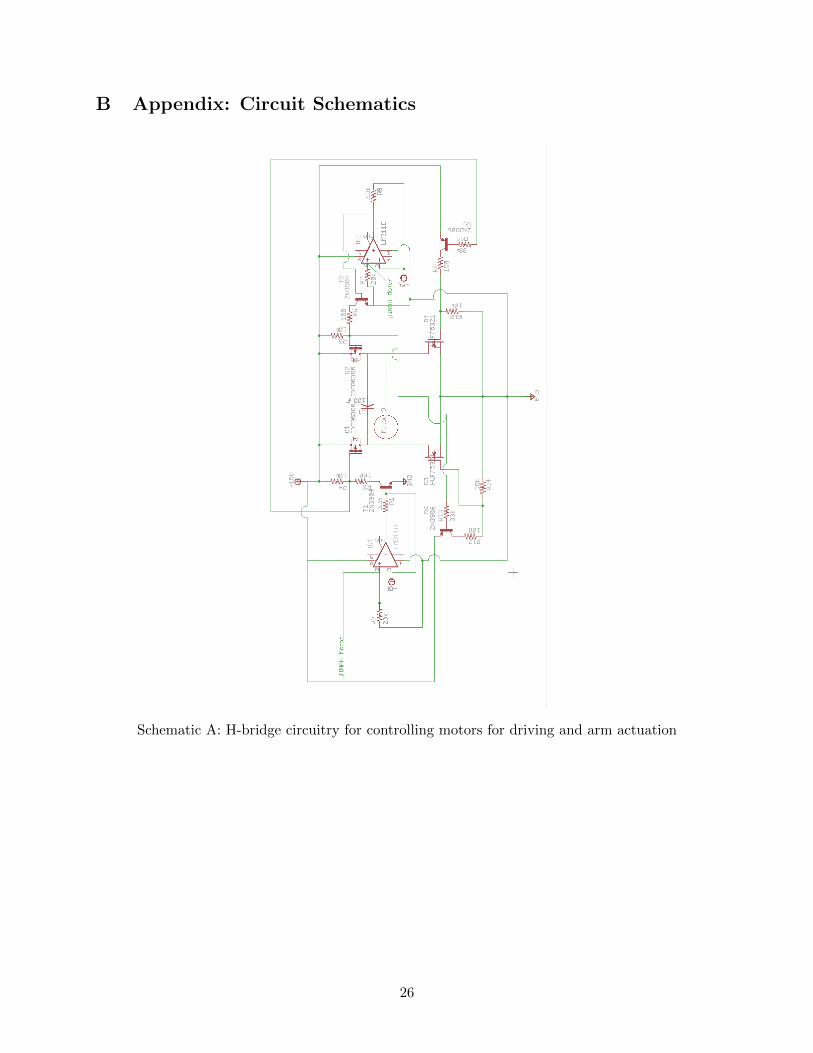
There will be two motors for driving, each powering one wheel using differential steering. Eachmotor will be connected to a motor output on TINAH via an external H-bridge with a comparatorattached. Similarly, another H-bridge is used for actuating the arm for picking up pets, shown inSchematic A.
6.2 Phototransistors
The QRD1114 phototransistor for tape following will be connected directly to an analog input pinon TINAH. Another QRD1114 will be placed on the side of the robot and connected to a digitalinput on TINAH with an adjustable comparator for detecting the pet marker tape. This is shownin Schematic B.
6.3 Photodiodes
Schematic C shows the circuit for the three identical IR detectors used for detecting the IR beaconsduring the competition.
6.4 Winch
One N-type MOSFET drives the motor for the winch. Since it does not need to be reversible, afull H-bridge is not needed.
15

6.5 Pickup Microswitches
The microswitches connected to the lower and upper plates of the retrieval arm are connected asshown in Schematic D
Table 1: Table of TINAH Pin Connections
DigitalPin
Input/Output
0 Pet Marker QRD
1 Pickup Microswitch Lower
2 Pickup Microswitch Upper
3 Winch Enable
4 Wheel Encoder Left
5 Wheel Encoder Right
6 Zipline Detection
AnalogPin
Input/Output
0 IR Sensor Left
1 IR Sensor Right
2 Tape Follower QRD
3 IR Sensor Side
MotorPin
Output
0 Drive Motor Left
1 Drive Motor Right
2 Retrieval Arm Motor
3 Zipline Arm Motor
Table 2: Table of PCB Information
PCBNumber
Purpose Size(mm)
ComponentsConnected
RailsNeeded
1 H-bridges: Drive Mo-tors Left and Right,Retrieval Arm Motor,Zipline Arm Motor
180 x 70 TINAH, 4 DCmotors
GND, 5V, 15V
2 IR detection circuitry 90 x 70 TINAH, 2 photo-diodes
GND, 5V, ±9V
16

7 Software and Code Algorithms
The software will operate statefully, with one main control loop that handles the primary strategyand execution. At the same time, a 10kHz timer interrupt will run in parallel which will handlethe time-sensitive operation of polling input pins. The main control loop will call upon a variety ofdifferent modes that describe the current operation at any given point in the program’s execution.A summary of the different modes and their transitions is described in Figure 18 below.
Figure 18: Software Modes
A more detailed description of the modes is shown in Appendix C.
7.1 I/O
On the 10kHz timer interrupt will be attached a procedure that handles pin inputs. Because thestandard analogRead function blocks until the ADC conversion finishes (approximately a 1000-cycleprocess), carrying out the conversion in parallel can significantly decrease loop latency. Additionally,polling digital pin inputs on the timer interrupt can provide a better guarantee that changes indigital inputs will not be missed because of latency in the main loop.
Inputs to digital pins 0 to 3 were chosen because of their ability to trigger external interrupts. Asa result, we will not poll these pins on the timer interrupt.
7.2 Positional Correction
The encoders, tape-seeking QRD, and side QRD make up the position correction mechanism. Usingall of the below methods, we can accurately navigate the course.
7.2.1 Tape Following
Tape following is the procedure of using a positional feedback model to adjust velocity based on aphysical track. The analog tape-seeking QRD is read into the following formula which calculatesan output value δθ based on the QRD reading Q:
−δθ = GP (Q−QT ) +GI
∫ t
0(Q−QT )δt+GD
δ(Q−QT )
δt
17

where the gains GP , GI , GD are to be empirically determined, and QT is the desired value of Q (inthis case, the half-way point between the black and white readings). The robot will then attemptto follow the boundary between the tape and the non-taped area.
7.2.2 Dead Reckoning
Dead reckoning is the process of calculating position based on an initial condition and velocity dataover the course of travel. From encoder data, we can derive estimates for the change in positionand angle with numerical integration. The number of encoder ticks corresponds proportionally tothe instantaneous left and right wheel velocities vl and vd. With a distance of l between the twowheels, the instantaneous change in bearing dθ is
dθ
dt= ω =
vr − vll
and the magnitude of the velocity of point located in centre c of the wheels is simply
|vc| =vr + vll
giving us formulaedx
dt= |vc| cos θ
dy
dt= |vc| sin θ
which we can approximate and discretize into
δx = δt |vc| cos θ
δy = δt |vc| sin θ
with vr and vl determined by
vwheel = sgn(ωwheel)δEwheel
δtrwheel
where E is the integer number of encoder ticks on a wheel.
7.3 Error Handling
7.3.1 Unable to Retrieve Pet in Loft
We will make several attempts at this, adjusting the position of the robot each time. If after acertain number attempts we have not retrieved the pet, we will move on to the next stage.
7.3.2 Lost Tape
We will adjust proportional, differential, and integral constants to minimize this risk. Additionally,using wheel encoders allows us to have an additional input, which we can use to correct position ifthe tape is lost.
18

8 Risk Assessment and Contingency Planning
Table 3: Risk Assessment
Risk Condition Level ofRisk
Impact to Project Change to Work Plan ExpectedDate of RiskDecision
Unable to attachto zipline
High Robot can’t go back tosafety zone
Find other ways to attach tozipline
End of June
Pets fall off robotarm as it is beingpicked up
Medium Experiment with differ-ent magnets strength orfind alternative ways topick up pet
Find other ways to attach tozipline
End of June
Pets stack on-topof each other andfall off basket
VeryLow
Unable to save pets Change shape of basket Mid July
Unable to detectIR Beacon
Low Robot may not reach zi-pline very reliably
Move in a straight line afterthe tape is finished, until ithits the box. It should becloser to the IR Beacon. ORthe robot can drive back tosafety zone
Beginning ofJuly
Unable to prop-erly follow tape
Low Unable to complete thechallenge
Test following tape in a vari-ety of lighting conditions
End of June
Robot tilts toomuch as it slidesdown zipline
Medium Unable to save severalpets
Adjust shape/size of basketcarrying the pets, or changeposition of zipline arm
End of July
Unable locate peton loft
Low Unable to pick up pet Experiment with using sev-eral attempts to adjust loca-tion and lowering robot arm
Mid July
Run over pet onmiddle of path
Low Unable to collect thatpet, cause problems intape-following and pick-ing up other pets
Adjust height and materialmetal piece used to pick upthat pet
Beginning ofJuly
19

9 Task Schedule, Responsibilities and Major Milestones
9.1 Tasks
The main tasks will be construction of the chassis, retrieval arm and zipline apparatus sub-assemblies; construction of motor control and sensor circuitry; and software construction for eachstage as described in Appendix C.
9.2 Milestones
9.2.1 Tape Following
The first milestone will be reliably tape following. Meeting this milestone will require completion ofthe chassis sub-assembly, two motor control circuits, wheel encoder and tape following QRD circuitcompletion, and the tape follow subsection of the ’Follow/Retrieve’ software mode.
9.2.2 IR Homing
The second milestone will be reliably following the IR beacon. This milestone will require thecompletion of the first milestone as well as completion of the IR circuits and the Beacon Homingsoftware mode.
9.2.3 Functional Retrieval Arm
The third milestone will be a standalone arm that is capable of picking up and dropping off pets.This milestone will require the completion of the retrieval arm sub-assembly, the motor control cir-cuit, microswitch circuits, and the retrieve subsection of the ’Follow/Retrieve’ software mode.
9.2.4 Pet Retrieval
The fourth milestone will be our robot running through the course and retrieving pets 1-5. Thismilestone will require the completion of milestones 1-3, the pet marker tape QRD circuitry, andboth the ‘Follow/Retrieve’ and ‘Beacon Homing’ software modes.
9.2.5 Rubble Excavation
The fifth milestone will be successfully retrieving pet 6. This will require completion of milestones1-4 and the ‘Rubble Excavation’ software mode.
9.2.6 Functional Zipline
This milestone will be a standalone zipline assembly that can attach to the zipline. This can beaccomplished in parallel with milestones 3 and 4. This milestone will require the completion of the
20

zipline apparatus sub-assembly, motor control circuits for the winch and delivery system, and theswing and winch sections of the ‘Zipline/Return’ software mode.
9.2.7 Zipline Use
This milestone will be our robot attaching to and using the zipline. This will require the completionof the chassis assembly and drive systems, the ‘Functional Zipline’ milestone, the side IR sensingcircuit, and the ‘Zipline/Return’ software mode.
9.2.8 Complete Course
This milestone will be our robot successfully completing the entire course. This will require the com-pletion of all other milestones and the integration of all sub-assemblies and software modes.
Table 4: Task Schedule
Week FJORDBOTTEN LIM LIU ZHANG
7 Chassis ChassisDrive
Drive Position CorrectionRetrieval Arm
8 Retrieval Arm SensorsArm Circuit
SensorsArm Circuit
Retrieval ArmRetrieval Code
9 Zipline Zipline CodeTesting Retrieval
Other Circuits ZiplineRubble Excavation
10 TestingRebuilding?
TestingRebuilding?
TestingRebuilding?
TestingRebuilding?Dead Reckoning?
111213
Shared Goals:Retrieves pets on groundRetrieves pet on raftersRetrieves pet in rubbleCan zipline back intactIntegrate dead reckoning into tape following
21

A Appendix: Calculations
A.1 Rear Wheel Torque
From Solidworks’ analysis of our CAD models, we have an upper bound m of 5 kg on the assembly’sweight. The height hG of the centre of gravity G off the ground is 0.144 m. The horizontal distancelA from the back (driven) wheels at A to G is 0.085 m. The horizontal distance lB from the frontsupport B to G is 0.134 m. From our measurements, the ramp has an incline of 8. The rearmotors apply a frictional force FF on the back wheels, and the front support is estimated to havea coefficient of static friction µ = 0.2. Applying force and moment balancing equations on a staticbody,
ΣFx = 0 : NAı+NB ı−mg cos 14ı = 0
ΣFy = 0 : FF − µNB −mg sin 14 = 0
ΣM = 0 : NBlB −NAlA + FFhG − µNBhG = 0
Solving these equations, we obtain 9.7 N force necessary to drive the assembly out of stasis on theramp, which will be the most difficult part of the course. The wheels have radius 2.8 cm, so a gearratio of 3:1 will be sufficient to sustain movement with less than half of maximum torque.
A.2 Actuator Torque
Again, from the Solidworks analysis, the actuator arm has a centre of mass 9 cm from the pivot andweighs 0.535 kg when it is loaded with a pet. This requires a torque of 48 Ncm, and consequentlya gear ratio of 5:1 will allow the motor to run at half of maximum torque.
A.3 Zipline Arm Torque
The zipline arm has a mass of 0.117 kg which is centred 1.5 cm from the pivot. This is a 1.7 Ncmmoment required, which the motor can run at one-tenth of maximum torque without any gear-ing.
A.4 Winch Torque
The robot has an upper bound of 5 kg on mass. The winch pulley has a radius of 1 cm, which canincrease to an upper bound of 2 cm when the belt is wrapped around the spindle. This requires anupper bound of a 100 Ncm moment. A gear ratio of 1:40 is used, allowing the motor to run at justover half of maximum torque.
22

A.5 IR Sensing Circuit Value Validation
A.5.1 DC Block
Since:
fcutoff =1
2πRC
With R = 1kΩ and C = 100nF
fcutoff =1
2π(1000)(100× 10−9)= 1.59kHz
This will allow us to block all frequencies below about 1.5kHz which will functionally block DCand unwanted low frequencies.
DC Block
A.5.2 Amplifier Calculations
VoVi
=R1
R2=
47kΩ
10kω= 4.7
This will give us a five times amplification of the signal.
Amplifying Circuit
23

A.5.3 Band Pass Calculations
A high pass filter and a low pass filter in series (see diagram below) will form a band pass filterwith upper and lower limits determined by:
fcutoff =1
2πRC
We want both cutoff frequencies to be 10kHz so that the band around the desired frequency is asnarrow as possible. Therefore, the capacitors and resistors used in each section of the band passfilter will be the same.
Using R = 3.3kΩ and C = 4.7nF we get:
fcutoff =1
2π(3700)(4.7× 10⁻⁹)= 10.26kHz
as desired.
Band Pass Filter
24

A.5.4 Peak Detector Calculations
So that the input to the TINAH is a non-oscillatory analog signal, we will need a peak detector.This will be a rectifying circuit consisting of a resistor and a capacitor. Since the charge/dischargetime of an RC circuit is
τ = RC
we need to pick these values so that the charge time is as short as possible and the discharge timeis long enough to compensate for the voltage drop due to the oscillation of the IR signal. We choseR = 33kΩ and C = 100nF so that τ = 33000(100 × 10( − 9)) = 3.3ms so that the discharge timewould be longer than the period of the wave, keeping voltage relatively constant, and short enoughthat IR following will be functional.
Peak Detector
25
B Appendix: Circuit Schematics
Schematic A: H-bridge circuitry for controlling motors for driving and arm actuation
26

Schematic B: QRD1114 circuitry for tape following
Left QRD1114 is for general tape following; right QRD1114 is for detecting tape leading topet.
27

Schemtic C: Circuitry for 10kHz IR beacon detector
28

Schematic D: circuitry for controlling winch
Schematic E: circuit for microswitch detecting pet pick up
29

C Appendix: Software Modes
Table 5: Table of Software Modes
Mode Description
Main Menu This is the mode automatically entered when the board boots. The knobsare used to cycle between menu options. Additionally, any mode can becanceled to return to the Main Menu.
Options Menu Allows runtime parameters to be modified using the second knob.
Segment Select Starts the selected mode from a list containing modes during program exe-cution.
Course Begin Transitions to the Follow/Retrieval mode.
Follow/Retrieval Follows the tape and picks up the first three animals. Upon reaching theend of the tape (once all horizontal marks have been detected), switches tothe Beacon Homing mode.
Beacon Homing Using the two forward IR sensors, navigates towards the IR beacon. Picksup the elevated pet on the rafters by measuring distance from the end of thetape. Switches to Rubble Excavation upon IR sensor intensity reaching athreshold to be determined empirically.
Rubble Excavation Turns 90 degrees and brushes off the top layer of foam using the arm. At-tempts to find and retrieve the pet buried in the foam, and upon retrievingit (or on approaching the 2 minute time limit), switches to Zipline/Return.
Zipline/Return Uses the side IR sensor to align the robot with the beacon, raises the ziplinearm, and cranks the winch up to return to the Safe Area. Returns to MainMenu afterwards.
30