automated mathematical-based rigging design system for
TRANSCRIPT

Automated Mathematical-Based Rigging Design System
for Heavy Industrial Modules
Seyedmohammadamin Minayhashemi
A Thesis
In the Department
of
Building, Civil, and Environmental Engineering
Presented in Partial Fulfillment of the Requirements
For the Degree of
Master of Applied Science (Civil Engineering) at
Concordia University
Montreal, Quebec, Canada
October 2019
© Seyedmohammadamin Minayhashemi, 2019

Concordia University
School of Graduate Studies
This is to certify that the thesis prepared
By: Seyedmohammadamin Minayhashemi
Entitled: Automated Mathematical-Based Rigging Design System for Heavy Industrial Modules
and submitted in partial fulfillment of the requirements for the degree of
Master of Applied Science (Civil Engineering)
Signed by the final Examining Committee:
________________________________Chair
Dr. M. Nik-Bakht
_____________________________Examiner
Dr. A. Hammad
_____________________________Examiner
Dr. F. Nasiri
_____________________________Supervisor
Dr. S. H. Han
Approved by_________________________________________
Dr. Michelle Nokken, Graduate Program Director
October 31, 2019 ______________________________________
Dr. Amir Asif, Dean, Gina Cody School of Engineering and Computer Science

iii
Abstract
Automated Mathematical-Based Rigging Design System for Heavy Industrial Modules
Seyedmohammadamin Minayhashemi
Modular-based heavy industrial construction projects typically involve the use of mobile
cranes to lift and place large heavy prefabricated modules. These modules must be lifted vertically,
raised evenly, and maintained in a level position during the lift in order to prevent them from
deflecting and, more importantly, to mitigate safety issues regarding potential rigging failure. In
this respect, a comprehensive crane lift study at the planning stage of the project is required to
ensure the lifts are successful and to improve safety and productivity. One of the most tedious and
time-intensive tasks involved in conducting the lift study is the design of the rigging assemblies,
which are the link between the crane hook and the module. In practice, however, this task is
performed manually and relies heavily on guesswork, which is error-prone and time-consuming,
especially when the center of gravity is offset from the center of the module. Poorly designed
rigging assemblies are only detected at the job site when the module does not raise evenly at the
beginning of the lift, which then results in wasted time and productivity loss as the assembled
components have to be unrigged and properly adjusted. To overcome these limitations, this thesis
proposes an automated mathematical-based rigging assembly design system that consists of: (i)
the solver analysis, which calculates the sling angles and performs the calculations required to
balance the module; (ii) the rigging assembly designer, which determines the required capacity of
the rigging components and selects the suitable riggings from the database; (iii) the 3D visualizer,

iv
which creates a 3D model of the designed rigging assembly. This framework enables lift engineers
to create rigging assembly designs more precisely and expeditiously. The methodology is validated
in a case study.

v
Acknowledgements
First and foremost, I would like to express my deepest gratitude to my supervisor Dr. SangHyeok
Han for his constructive comments and warm encouragement on this work.
I would also like to show my greatest appreciation to Dr. Ahmed Bouferguene at the University of
Alberta. The door to his office was always open whenever I ran into a trouble spot or had a question
about my research.
Special thanks to Dr. Jacek Olearczyk and Mr. Joe Kosa, my supervisors at NCSG Engineering
Ltd, who gave me all the freedom to pursue my research at the company.
I am indebted to my parents for their unconditional love and support in my journey to get my
Master’s degree and at every stage of my life.
And finally, last but by no means least, I cannot find words to express my gratitude to my beloved
wife. Without her endless patience and support I could not imagine finishing my Master’s degree.

vi
Table of Contents
Table of Figures ........................................................................................................................... viii
Table of Tables .............................................................................................................................. ix
Table of Parameters ........................................................................................................................ x
Chapter 1: Introduction ................................................................................................................... 1
Chapter 2: Literature Review .......................................................................................................... 6
Chapter 3: Proposed Methodology ............................................................................................... 11
3.1 Slinging Arrangement of Modules with N Lifting Points .............................................. 13
3.2 Sling Length Adjustment ............................................................................................... 16
3.3 Solver Module ................................................................................................................ 20
3.3.1 Task 1 ...................................................................................................................... 20
3.3.2 Task 2 ...................................................................................................................... 28
3.4 Designer Module ............................................................................................................ 30
3.4.1 Preliminary Design ................................................................................................. 30
3.4.2 4-Point Pick Segments ............................................................................................ 32
3.4.3 2-Point Pick Segments ............................................................................................ 37
3.4.4 Selecting Rigging Components From The Database .............................................. 40
3.5 3D Visualizer Module .................................................................................................... 48
Chapter 4: Case Studies ................................................................................................................ 50
4.1 Case Study 1 ................................................................................................................... 50
4.2 Case Study 2 ................................................................................................................... 57
Chapter 5: Future Works ............................................................................................................... 62
Chapter 6: Conclusion................................................................................................................... 64

vii
References ..................................................................................................................................... 66

viii
Table of Figures
Fig. 1. Traditional rigging assembly and lift frame ........................................................................ 2
Fig. 2. 4-point pick rigging assembly with diagonal slings ............................................................ 7
Fig. 3. The proposed methodology ............................................................................................... 11
Fig. 4. Lifting an industrial 12-point pick module ........................................................................ 14
Fig. 5. Slinging arrangement of modules with N lifting points .................................................... 15
Fig. 6. Sling length adjustment to balance the load with the chain of shackles ............................ 18
Fig. 7. Sling length adjustment using turnbuckles in 2-point pick segments ............................... 19
Fig. 8. Two-dimensional drawing of a 4-point pick rigging assembly ......................................... 23
Fig. 9. Upper part of 2D drawings shown in Fig. 8 ...................................................................... 25
Fig. 10. Lower part of 2D drawings shown in Fig. 8 .................................................................... 25
Fig. 11. Preliminary rigging assembly .......................................................................................... 31
Fig. 12. 4-point pick segments designing procedure .................................................................... 33
Fig. 13. Forces applied to the module and the rigging assembly .................................................. 34
Fig. 14. 2-point pick segments designing procedure .................................................................... 38
Fig. 15. Feasible slinging arrangements of a 2-point pick segment .............................................. 39
Fig. 16. Shackle sheet in the Excel database ................................................................................ 41
Fig. 17. Spreader bar sheet in the Excel database ......................................................................... 44
Fig. 18. Sling sheet in the excel database ..................................................................................... 45
Fig. 19. Turnbuckle sheet in the excel database ........................................................................... 46
Fig. 20. Constant and variable parameters of a spreader bar block .............................................. 49
Fig. 21. The user interface of the proposed methodology ............................................................ 51
Fig. 22. Calculations of sling angles and RAI in two-dimensional planes .................................... 53

ix
Fig. 23. Results of the 2-point pick segment design algorithm .................................................... 55
Fig. 24. Final result of the 6-point pick rigging assembly ............................................................ 56
Fig. 25. The user interface of the proposed methodology ............................................................ 57
Fig. 26. Calculations of sling angles and RAI in two-dimensional planes .................................... 59
Fig. 27. Final result of the 4-point pick rigging assembly ............................................................ 61
Table of Tables
Table 1. Capacity chart of a spreader bar (lbs.) ............................................................................ 36
Table 2. Selected rigging components for the preliminary rigging assembly .............................. 52
Table 3. Selected rigging components for the preliminary rigging assembly .............................. 58
Table 4. the required and rated capacity of the selected rigging components .............................. 60

x
Table of Parameters
Parameter Description
a,b,c Sides of the triangle (Fig. 8)
Ci Inside length of i shackle (Eq. (16))
f Minimum absolute difference between the required amount of increase and
the total length made by the chain of shackle (Eq. (16))
FL1, FR1 Sling forces at the first level of the rigging assembly (Fig. 13)
FL2, FR2 Sling forces at the second level of the rigging assembly (Fig. 13)
HDesired Desired total height of the 2-point pick segment (Eq. (23)
HRemain Remaining height (Eq. (23)
HSlings Total height of slings in the 2-point pick segment (Eq. (23)
HW Width of the hook (Fig. 8)
Max(SLDB) Maximum sling length available in the database (Fig. 14)
Max(TBL) Maximum opening length of the turnbuckles available in the database (Fig.
14)
Min(SLDB) Minimum sling length available in the database (Fig. 14)
Min(TBL) Minimum opening length of turnbuckles available in the database (Fig. 14)
N Total number of shackles available with different sizes (Eq. (16))
ni The number of i shackles used in the chain (Eq. (16))
ofst COG offset from the lifting point (Fig. 8)
RAI Required Amount of Increase (Fig. 6)
xi
SB Distance from the right/left side of the spreader bar to the lifting point on the
right/left side (Fig. 8)
SBL Length of the spreader bar (Fig. 8)
SBLx Horizontal projection of SBL (Fig. 8)
SL Distance from the left side of the spreader bar to the left side of the hook
(Fig. 8)
SL1st Sling length at the first level of the 2-point pick segment (Eq. (23)
SL2nd Sling length at the second level of the 2-point pick segment (Eq. (23)
SL3rd Sling length at the third level of the 2-point pick segment (Eq. (23)
SLx Horizontal projection of SL (Fig. 8)
SR Distance from the right end of the spreader bar to the right side of the hook
(Fig. 8)
SRx Horizontal projection of SR (Fig. 8)
WL, WR Weight forces applied to the lifting points (Fig. 13)
x Distance from the right side of the hook to the vertical line crossing the COG
(Fig. 8)
α Angle of sling attached to the bottom right of the spreader bar with the
vertical line (Fig. 8)
β Angle of sling attached to the bottom left of the spreader bar with the vertical
line (Fig. 8)
γ Slope of the spreader bar (Fig. 13)
δ The angle of plane which contains the slings and the spreader bar at the
second level with the vertical plane (Fig. 13)
θL Angle of sling attached to the top left of the spreader bar with the spreader
bar (Fig. 8)
θR Angle of sling attached to the top right of the spreader bar with the spreader
bar (Fig. 8)
σ Angle of sling attached to the top left of the spreader bar with the horizontal
line (Fig. 8)

1
Chapter 1: Introduction
Modularization is a growing trend in construction thanks to its efficiency in terms of time,
cost and quality improvement [1]. This mode of construction thus is the solution of choice for
heavy industrial projects, especially oil refinery facilities, in the province of Alberta, Canada. In
these projects, hundreds of modules are prefabricated in a controlled environment, transported to
the job sites, lifted from their pick locations, and finally erected in their planned position. These
modules which have N lifting points (4 to 16 lifting points depending on the module length) can
typically be classified as pipe racks, cable trays and building modules [2]. Furthermore, their
weights are up to 160 tons with the following dimensions: (i) up to 7.3 m (24 ft.) in width; (ii) 42
m (138 ft.) in length; and (iii) 8.4 m (27.5 ft.) in height [4].
In order to prevent the modules from tilting, they are required to be lifted vertically and
evenly from the extension of the module’s columns which are located on the top of the modules.
Lifting the modules unevenly can potentially result in deflecting them and, more importantly, due
to unexpected distribution of the load throughout the rigging assembly, increase the risk of rigging
failure, thus lifting safety issues. At this junction, it should be noted that, rigging failure is one of
the major causes of crane accidents. According to a study based on the Occupational Safety and
Health Administration (OSHA) database, 28.1% of the fatal crane accidents happened in the
United States from 2002 to 2012 caused by failure of wire ropes, slings and hoist lines. The other
causes of fatal crane accidents were overturn/tips (8.6%), collapse (11.4%), ground conditions
(3.6%), power line contact (5.6%), overloading/unstable (26%), signal/communication error
(9.4%), and others (7.3%) [5].
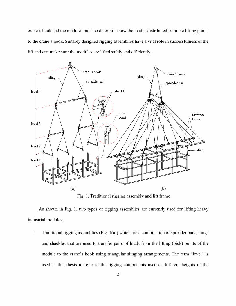
Rigging assemblies are generally used to not only build physical connection between the
2
crane’s hook and the modules but also determine how the load is distributed from the lifting points
to the crane’s hook. Suitably designed rigging assemblies have a vital role in successfulness of the
lift and can make sure the modules are lifted safely and efficiently.
(a) (b)
Fig. 1. Traditional rigging assembly and lift frame
As shown in Fig. 1, two types of rigging assemblies are currently used for lifting heavy
industrial modules:
i. Traditional rigging assemblies (Fig. 1(a)) which are a combination of spreader bars, slings
and shackles that are used to transfer pairs of loads from the lifting (pick) points of the
module to the crane’s hook using triangular slinging arrangements. The term “level” is
used in this thesis to refer to the rigging components used at different heights of the

3
assembly. The number of levels in traditional rigging assemblies vary based on the number
of module’s lifting points.
ii. Lift frames (Fig. 1(b)) which are the newly emerged alternative to traditional rigging
assemblies. In lift frames, the load is firstly transferred from the lifting points to two long
beams running along the length of the module. A single spreader bar then transfers the load
from the two beams to the crane’s hook.
The design process for traditional rigging assemblies is laborious and time-consuming to
assemble compared to the lift frames [2]. The number of rigging components in traditional rigging
assemblies may reach to 150 pieces for large modules [3]. However, this technology is still widely
used in practice because project owners and lifting contractors are very familiar with the solutions
that need to be implemented to circumvent any potential challenge that may unexpectedly occur
on the construction site. Moreover, the lift frames are 30 to 40% heavier than the traditional rigging
assemblies depending on the size of the module to be lifted. In addition, as shown in Fig. 1(b), the
length of lift frame beams may exceed the module’s length which increases the risk of collision
with crane’s boom as well as other site obstacles. It should be noted that this thesis focuses on
overcoming the limitations of designing traditional rigging assemblies using an automated
procedure which integrates rigging analysis calculations with 3D visualization.
As mentioned earlier, unevenly lifting a module not only involves safety issues regarding
rigging failure but also increases the risk of damage to the structural components of the module.
To solve this issue, in practice, the assembled rigging components need to be unrigged and adjusted
properly to balance the load which leads to reduce lifting productivity due to waste of design and
lifting times. In this respect, designing a rigging assembly which ensures the module is lifted

4
evenly and maintained in a level position during the lift is paramount.
The design process used to assemble rigging system consists of the following tasks:
i. Calculating the required capacity of each rigging component based on the module
information such as its weight, dimensions, the Center Of Gravity (COG) position, and
number of lifting points.
ii. Selecting suitable rigging components from their capacity charts based on the required
capacities and dimensions;
iii. Calculating the total weight of the rigging assembly which is used in crane selection.
iv. Creating a 3D model of the rigging assembly to identify whether the selected rigging
components can actually be used together (size compatibility of the selected rigging
components). The developed 3D model, as a part of a more comprehensive 3D lift study,
is then used to ensure that the module and rigging assembly do not collide with crane’s
boom and/or site obstacles.
Manually performing these tasks, especially when the COG is offset from the center of the
module, is a tedious and error-prone process relying heavily on guesswork which can take from
0.5 to 4 hours per module depending on the number of lifting points on the modules as well as the
engineer’s experience.
To overcome these limitations, this thesis proposes an automated mathematical-based
rigging assembly design system which consists of: (i) collecting module and available rigging
component information; (ii) a solver analysis which calculates the sling angles and performs the
required calculations for balancing the module; (iii) rigging assembly designer which determines

5
the required capacity of the rigging components and selects the suitable riggings from the database;
(iv) rigging assembly design alternatives; and (v) 3D visualizer which creates a 3D model of the
designed rigging assembly. The proposed system is developed in AutoCAD platform using
Application Programming Interface (API).

6
Chapter 2: Literature Review
A significant number of researches have been done in the area of heavy lift studies to address
issues regarding crane selection [[4], [6]-[8]], crane lift path planning [[9]-[12]], and crane
operation simulation [[13]-[16]]. On the other hand, research on the development of design
frameworks for crane rigging assemblies has received less attention in both academia and industry
despite their importance for safety and efficiency. In practice, rigging assembly design is time-
consuming and error-prone and is often associated with loss of productivity and safety reduction.
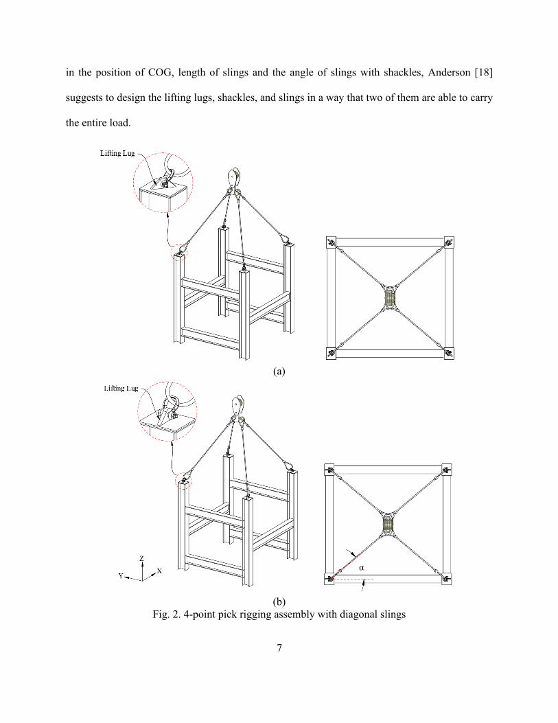
One common slinging arrangement for lifting modules referred to as 4-point pick modules,
consists in attaching 4 diagonal slings directly from the lifting points to the hook (Fig. 2). In the
ideal scenario where the COG is exactly at the center of the module, the length of the slings used
to transfer the load from the module to the crane’s hook in a 4-point pick scenario need to be
exactly equal (assuming the pick points are distributed symmetrically with respect to the COG).
In practice, however, because the COG is likely to be offset from the geometric center of the
module, the length of the slings need to be adjusted in order to have a balanced transfer of the load
which will ensure that the lifted module stays level at all time. Moreover, the alignment of the
lifting lugs, which are the most vulnerable places of the module [17], is important in this
configuration. Each of the lifting lugs must be in plane towards the COG (Fig. 2(a)). If the lifting
lugs are aligned toward X axis direction (Fig. 2(b)), the load is not applied on the shackles in-line
due to the angle that slings make with the shackles (α) which referred to as side-loading [18] . In
that case, the working load limit of the shackle must be reduced based on the angle of sling with
shackle according to its supplier’s manual. The working load limit of the shackle may be reduced
to as low as 50% of its full capacity in side-loading applications [19]. Considering the uncertainties
7
in the position of COG, length of slings and the angle of slings with shackles, Anderson [18]
suggests to design the lifting lugs, shackles, and slings in a way that two of them are able to carry
the entire load.
(a)
(b)
Fig. 2. 4-point pick rigging assembly with diagonal slings

8
In previous work, Sam [20] developed a spreadsheet to determine the load distribution
between the 4 slings considering the position of COG and sling lengths. The position of each lifting
point, length of slings and the COG position of the module are the inputs of his study whereas the
width of the hook is not considered due to its insignificant effect on the sling load and distribution.
The scope of Sam’s study is limited to 4-point pick modules unless an independent and separate
analysis is done for the modules that have more than 4 lifting points and are lifted with multiple
cranes.
Lifting points of modules may be located at the bottom of the modules. Lifting from bottom,
however, involves risk of instability if the module’s COG is too high as it may be dumped in the
course of its motion. In this respect, for 4-point pick modules which are required to be lifted from
their bottom, an analytical necessary and sufficient criterion for Lyapunov stability or asymptotic
stability was suggested by Longman and Freudenstein [21]. They defined an expression for the
margin of stability in which the disturbance forces caused by crane hook motion during the lift can
be tolerated. Their methodology cannot be applied on modules with more than 4 lifting points.
Unless required by the size of the payload, e.g. long vessels, wind turbine propellers, etc.,
which necessitates vertical orientation at the set point single crane lifts operations are generally
preferred to their tandem crane counterparts since the risk associated with the former is lower in
comparison to the latter [7]. In this regard, Chen et al. [22] suggested a numerical model for
manipulating the angle of twin-hoisted objects using one crane. In their model, the hoist lines of
the boom and auxiliary jib need to be adjusted to accommodate the desired object angle during the
lift. However, this model can only be used to control the object angle in one direction. In addition,
the available capacity of the crane becomes more limited when crane’s auxiliary jib is used which

9
is necessary in their model.
As described in previous section, compared to the other research areas regarding heavy lift
studies (crane selection, crane lift path planning, crane operation simulation, etc.) there are
relatively less researches and/or practical reports in terms of methods to support the design of
rigging components. However, there are a few commercial software that can help designing
rigging assembly.
Industry-academic researches and developments have led to computer-aided heavy lift
planning systems in order to assist lift engineers in the planning phase of the heavy lift projects. A
Computer-Aided Rigging (CAR) system was developed by Brown & Root company which
reportedly integrates basic rigging analysis and documentation of rigging plans in a CAD platform
[23]. At Bechtel, a heavy lift planning and visualization software called Automated Lift Planning
System (ALPS) was developed for crane selection, rigging assembly design and 3D simulation
features [24]. At the University of Texas at Austin, a Heavy Lift Planning System (HeLPS) was
built in order to facilitate tasks such as determining crane location, ground support and lift path
clearances. HeLPS employed a 3D visualization package called as Walkthru which was also
developed in the MicroStation environment [25]. Other standalone pieces of software such as 3D
Lift Plan [26], CRANEbee [27] and kranXpert [28] have been commercially available. However,
these software programs have yet to fully succeed in terms of being widely adopted due to the
following reasons: (i) they assist lift engineers to design rigging configurations manually or semi-
manually; and (ii) they may result in wasted assembly time on-site since actual rigging components
(e.g., slings, spreader bars, and shackles) are represented by the software programs as simple solid
geometries, which are not capable of indicating size incompatibilities between rigging components

10
that may result in the components not being able to be assembled in real life
In order to overcome these limitations, this thesis presents a mathematical-based rigging
assembly design system which automates the design of rigging assemblies for a large number of
modules which are generally used in heavy industrial construction projects. The proposed system
consists of: (i) collecting module information; (ii) automating the rigging analysis calculations; (iii)
reporting the result of analyses; and (iv) visualizing the rigging assembly in 3D environment.
Moreover, the proposed framework provides rigging assembly information (e.g., overall heights
and weights) as one of the results from the proposed system which is an essential input to complete
the crane selection, crane lift path planning, and crane operation simulation successfully and
efficiently.
11
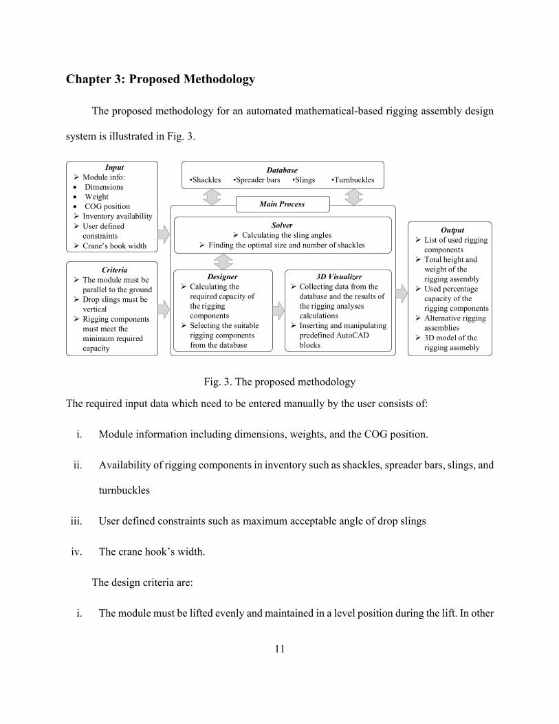
Chapter 3: Proposed Methodology
The proposed methodology for an automated mathematical-based rigging assembly design
system is illustrated in Fig. 3.
Fig. 3. The proposed methodology
The required input data which need to be entered manually by the user consists of:
i. Module information including dimensions, weights, and the COG position.
ii. Availability of rigging components in inventory such as shackles, spreader bars, slings, and
turnbuckles
iii. User defined constraints such as maximum acceptable angle of drop slings
iv. The crane hook’s width.
The design criteria are:
i. The module must be lifted evenly and maintained in a level position during the lift. In other
Input
➢ Module info:
• Dimensions
• Weight
• COG position
➢ Inventory availability
➢ User defined
constraints
➢ Crane’s hook width
Criteria
➢ The module must be
parallel to the ground
➢ Drop slings must be
vertical
➢ Rigging components
must meet the
minimum required
capacity
Database
•Shackles •Spreader bars •Slings •Turnbuckles
Designer
➢ Calculating the
required capacity of
the rigging
components
➢ Selecting the suitable
rigging components
from the database
3D Visualizer
➢ Collecting data from the
database and the results of
the rigging analyses
calculations
➢ Inserting and manipulating
predefined AutoCAD
blocks
Main Process
Output
➢ List of used rigging
components
➢ Total height and
weight of the
rigging assembly
➢ Used percentage
capacity of the
rigging components
➢ Alternative rigging
assemblies
➢ 3D model of the
rigging assmebly
Solver
➢ Calculating the sling angles
➢ Finding the optimal size and number of shackles

12
words, the lifted module must be parallel to the ground. Otherwise, the load is unexpectedly
distributed throughout the rigging assembly and, in consequence, potential rigging failure
and module deflection may be occurred
ii. The angle between the drop slings (slings at the first level of the rigging assembly attached
to the lifting points) and the module must be perpendicular so that only vertical tension
forces are applied on the module’s columns which prevents the module from bending
iii. The selected rigging components must meet the minimum required capacity.
Failure to meet each of these criteria could jeopardize the safety during the lift.
Based on the input and criteria, the proposed methodology to design rigging assembly for
each of the modules involves mainly three modules:
i. Solver which performs two tasks: First, calculating the sling angles at each level of the
rigging assembly through solving a system of nonlinear equations; and second, finding the
optimal size and number of shackles, which are attached to slings to increase their lengths,
to satisfy the criteria (i) and (ii)
ii. Designer which calculates the required capacity of the rigging components based on the
module information and selects suitable rigging components that meet the required
capacity from the data considering their availability in the inventory.
iii. 3D visualizer which creates a 3D model of the rigging assembly in the AutoCAD platform
using AutoCAD Application Programming Interface (API). Creating the 3D model is an
essential step to identify size compatibility of the selected rigging components which
means whether the selected rigging components can actually be used together. If an

13
incompatibility issue is encountered, the user may choose to put constraints on the
availability of the rigging components that cause the error and start the design over again,
or to perform the required modifications manually. Moreover, as mentioned earlier, the
developed 3D model is used to ensure that the module and rigging assembly do not have
collision risks among crane’s boom and/or site obstacles. The 3D visualizer module
collects the required data from both the database and the results of the rigging analyses.
The collected data is then used in inserting and positioning the rigging components which
are stored as AutoCAD 3D blocks in the database.
Finally, the outputs of the system are mainly rigging designs (can be more than one single
design) which involve a list of selected rigging components, total height and weight of the rigging
assembly and proposed percentage capacity of the rigging components in accordance with
alternatives of the rigging assembly designed by the proposed methodology. The proposed
methodology which is developed using C# language assists lift engineers to design the rigging
assemblies automatically and efficiently for safe lifting.
Before describing more detail information for each of the three modules, the slinging
arrangement of modules with N lifting points (4 to 16 lifting points) and the concept of sling length
adjustment are described in the following sections.
3.1 Slinging Arrangement of Modules with N Lifting Points
As mentioned earlier, industrial modules may have N lifting points (4 to 16 lifting points
depending on the module length). Fig. 4 shows an industrial 12-point pick module during the lift
using traditional rigging assembly. Rigging assembly of these modules are designed with
combining 4-point pick and 2-point pick segments as shown in Fig. 5.

14
Fig. 4. Lifting an industrial 12-point pick module

15
4-point rigging assemblies are a fundamental segment in the rigging assembly of the modules.
They consist of 3 spreader bars; two of which are along the Y-axis and the other is along the X-
axis. The load is generally transferred from the lifting points to the hook or to the end of the
spreader bar located at the higher level. For instance, the 4-point pick segment that is used in 6-
point pick rigging assemblies transfers the load from the lifting points to the hook; and the 4-point
pick segments used in 8-point pick rigging assemblies transfer the load from the lifting points to
the end of the spreader bar located at the level 4.
Fig. 5. Slinging arrangement of modules with N lifting points
6-Point Pick
8-Point Pick
10-Point Pick
12-Point Pick
14-Point Pick
2 ×
2 ×
16-Point Pick
4-Point Pick + 2-Point Pick2×
4-Point Pick
4-Point Pick
4-Point Pick 2-Point Pick
+
+
2-Point Pick
4-Point Pick + 2-Point Pick2× + 2-Point Pick
4 × 4-Point Pick
4-Point Pick 6-Point Pick 8-Point Pick 10-Point Pick
12-Point Pick 14-Point Pick 16-Point Pick
YX
COG offset
direction
2-Point Pick

16
2-point pick segments, which use only one spreader bar along the Y-axis of the module, are
applied in the rigging assembly of the modules with 6, 10, 12, and 14 lifting points. These segments
are utilized either inside of the 4-point pick segments for the modules which have 6, 12, and 14
lifting points or in the middle of the whole rigging assembly for the modules which have 10 and
14 lifting points. In this respect, this thesis describes the concepts of the rigging design which are
2-point pick and 4-point pick segments instead of covering all of possible pick points.
3.2 Sling Length Adjustment
The length of slings used in the rigging assemblies needs to be adjusted for two main
purposes: (i) balance the module which must be parallel to the ground during the lift; and (ii) make
sure that all of the slings are taut and not slack so that they can have responsibility in terms of the
assigned load. The adjustments of the sling length are generally implemented by mounting a chain
of shackles or a turnbuckle to one end of the sling on where the imbalance of the load is existed.
When the COG is offset from the Center Of the Module (COM) in order to balance the load
in both X and Y direction, sling length adjustment is required at different levels of the rigging
assembly in accordance with X and Y axis. With respect of balancing the load in X direction, the
length of the sling, which is located on the opposite direction of the COG offset represented as red
lines in Fig. 5 at the highest level of the configuration, is increased. In order to balance the load in
Y direction, all of the slings on the opposite direction of the COG offset at the lowest level
illustrated as blue lines in Fig. 5 are lengthened.
For example, as shown in Fig. 6(a), the vertical line crossing the COG is on the right side of
the COM, meaning that the COG is offset to the positive X direction. Therefore, to balance the
load in X direction, the length of sling on the left side and above the spreader bar must be increased

17
by a specific amount, referred to as the Required Amount of Increase (RAI). It is worth mentioning
that, two slings above the spreader bar are always identical in length. Therefore, a chain of shackles
is used to take up the amount of slack between the sling end and the shackle attached to the spreader
bar (i.e. RAI) on the left side. The calculation of the RAI, and determining the size of number of
shackles are completed by the solver module.
In attaching additional shackles above the spreader bars, it should be noted that, the first
shackle that is attached to the spreader bar’s shackle, is used upside down with a bow-to-bow
connection (Fig. 6 (b)) to avoid potential interference between the shackle’s pin and the spreader
bar’s body. The next shackles in the chain could have any type of point-to-point connection
including bow-to-bow, pin-to-pin or pin-to-bow. It must be checked if the shackles are allowed to
be used in a point-to-point loading according to the supplier’s manual since not all the shackles
are designed for this application.

18
(a)
(b)
Fig. 6. Sling length adjustment to balance the load with the chain of shackles
When a 2-point pick segment is used in rigging assemblies, in order to make sure that all the
slings in this segment take the load, the total height of the 2-point pick segment must be adjusted
to accommodate: (i) the height of the 4-point pick segments when it is located inside of the 4-point
pick segments; and/or (ii) the height of the whole rigging assembly when it is located in the middle
of rigging assembly. Depending on the location of this segment in various N-point pick modules,
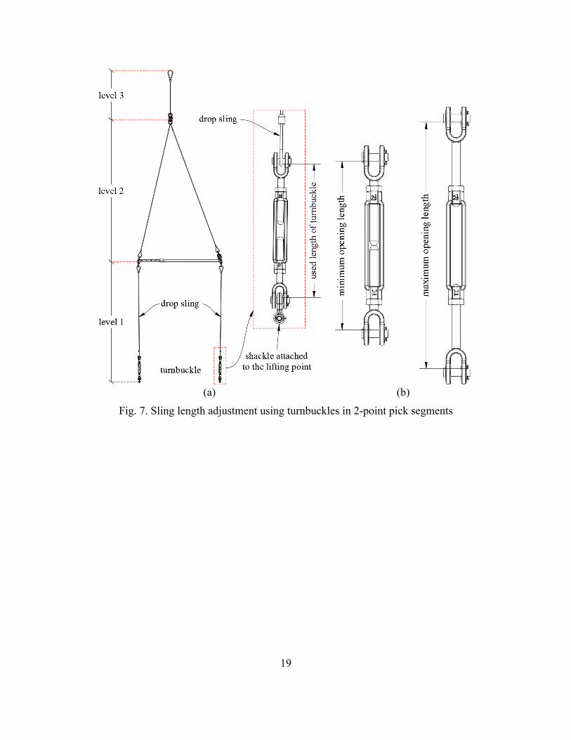
these conditions should be satisfied, accordingly. In this respect, as illustrated in Fig. 7(a), the
height of 2-point pick is adjusted by changing the length of turnbuckles mounted to the end of drop
slings based on a minimum or maximum opening length shown in Fig. 7(b). In selecting
turnbuckles, it is important to verify if the turnbuckle has enough length to take up the slack
between the end of drop sling and the shackle attached to the lifting point. The algorithm of
configuring 2-point pick segments will be explained in the designer module.
19
(a) (b)
Fig. 7. Sling length adjustment using turnbuckles in 2-point pick segments

20
3.3 Solver Module
The solver module is called within the main process of the proposed system to perform two
tasks: (i) calculating the sling angles and the RAI in the length of one of two slings above the
spreader bar for balancing the load through solving a system of 11 equations when the COG is
offset in X and/or Y direction. (ii) finding the optimal size and number of shackles that make a
total length which must be satisfied by as close as possible to the RAI.
3.3.1 Task 1
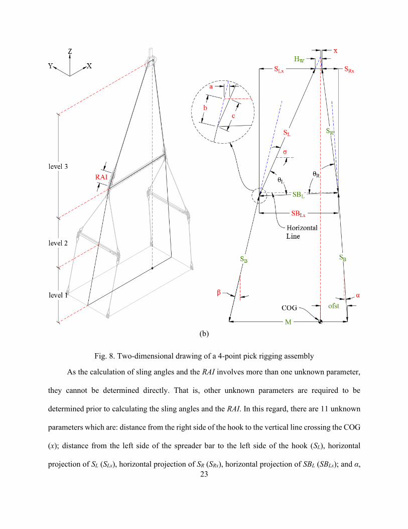
The sling angles at each level of the rigging assembly and the RAI are calculated in a two-
dimensional plane involving the spreader bar and the two slings above it. A 4-point pick rigging
assembly, which is a fundamental segment in rigging assemblies of heavy industrial modules, is
used to describe the parameters that are required in finding the sling angles and the RAI. Fig. 8
represents 4-point pick rigging assemblies where the length of the spreader bar at level 3 is longer
(Fig. 8(a)) or shorter (Fig. 8(b)) than the length of the module and the COG is offset from the
center of the module in positive X direction. If the actual COG is offset into negative X direction,
the same amount of offset from the module’s center is assumed to be in positive X direction and
the results of the designed rigging assembly are mirrored about XZ plane. In Fig. 8, the difference
between the length of spreader bar and the distance between the lifting points has been exaggerated
in order to show the angles more clearly. In practice, however, the spreader bars’ length is adjusted
by specific intervals to accommodate the distance between the lifting points on the module.
In setting up the equations by which the sling angles and the RAI are calculated, six known
parameters and three geometrical constraints are required initially. The known parameters are as
follows:

21
1. Width of the hook (HW).
2. Distance between the two end lifting points (M)
3. COG offset from the lifting point (ofst)
4. Length of the spreader bar (SBL)
5. Distance from the right end of the spreader bar to the right side of the hook (SR)
6. Distance from the right/left side of the spreader bar to the lifting point on the right/left side
(SB).
These parameters are determined by the user, module information, and results of a
preliminary design in which the COG is assumed to be at the middle of the module. The
preliminary design is performed by the designer module which will be explained later. The
geometrical constraints employed in setting up the equations are:
1. The extension of inclined lines above and below the spreader bar (illustrated as blue dash
lines in Fig. 8) must intersect each other on the vertical line crossing the COG (illustrated
as red dash lines in Fig. 8) to establish the equilibrium of the module and the rigging
configurations based on balancing forces which are the module’s weight force acting
vertically through the COG and the forces acting on the slings located in above and below
the spreader.
2. The line M must be balanced horizontally to satisfy the design criteria (i) described above
3. The line HW must be balanced horizontally since the crane’s hook is only rotated along Z
axis.
It is worth mentioning that, if the COG is offset from the module’s center, the spreader

22
bar has inevitably a slight slope when the module and spreader bar are not equal in length.
(a)
23
(b)
Fig. 8. Two-dimensional drawing of a 4-point pick rigging assembly
As the calculation of sling angles and the RAI involves more than one unknown parameter,
they cannot be determined directly. That is, other unknown parameters are required to be
determined prior to calculating the sling angles and the RAI. In this regard, there are 11 unknown
parameters which are: distance from the right side of the hook to the vertical line crossing the COG
(x); distance from the left side of the spreader bar to the left side of the hook (SL), horizontal
projection of SL (SLx), horizontal projection of SR (SRx), horizontal projection of SBL (SBLx); and α,

24
β, σ, a, b, and c as shown in Fig. 8. The unknown parameters are solved in a system of equations
where all the equations must be satisfied simultaneously. Previous work [29] used Wolfram
Mathematica kernel to solve the system of equations efficiently and effectively for the same
problem. Since this kernel is required many times leading to slow down the process time of the
proposed system, this thesis develops an algorithm to solve the system of equations within the
same manner in order to correspond to one of objectives in this thesis, efficient rigging
configuration design both on-site and during the design phase of construction projects in a short
manner.
It should be noted that, in any of the following equations that the symbols ±, ∓ are used, the
upper operator is chosen for Fig. 8(a) where the spreader bar is longer than the module’s length;
and the lower operator is chosen for Fig. 8(b) where the spreader bar is shorter than the module’s
length. In order to make it easier to follow the equations, Fig. 9 and Fig. 10 are provided to illustrate
the terms that are used in the equations for the upper and lower part of the Fig. 8 respectively. Fig.
9(a) and Fig. 10(a) are used for the case that the spreader bar is longer than the module’s length;
and Fig. 9(b) and Fig. 10(b) are used for the case that the spreader bar is shorter than the module’s
length.

25
(a) (b)
Fig. 9. Upper part of 2D drawings shown in Fig. 8
(a)
(b)
Fig. 10. Lower part of 2D drawings shown in Fig. 8

26
In the first step, using Eq. (1)-(2) (see Fig. 10) and Eq. (3) (see Fig. 8), the values of α, β,
and b, which are the only unknown parameters of these equations, are calculated.
𝑜𝑓𝑠𝑡(𝑆𝐵 𝑠𝑖𝑛 𝛼)⁄ =
(𝑀 − 𝑜𝑓𝑠𝑡)((𝑆𝐵 + 𝑏) 𝑠𝑖𝑛 𝛽)⁄ (1)
𝑆𝐵 𝑐𝑜𝑠 𝛼 = (𝑆𝐵 + 𝑏) 𝑐𝑜𝑠 𝛽 (2)
𝑆𝐵𝐿2 − (±𝑆𝐵 𝑠𝑖𝑛 𝛽 + 𝑀 ± 𝑆𝐵 𝑠𝑖𝑛 𝛼)2 − (𝑆𝐵 𝑐𝑜𝑠 𝛼 − 𝑆𝐵 𝑐𝑜𝑠 𝛽)2 = 0 (3)
By solving Eq. (1) and Eq. (2) for α, the value of β and b can be determined according to α
satisfying Eq. (4) and Eq. (5).
𝛽 = tan−1 ((𝑀 − 𝑜𝑓𝑠𝑡) 𝑡𝑎𝑛 𝛼
𝑜𝑓𝑠𝑡⁄ ) (4)
𝑏 =𝑜𝑓𝑠𝑡 × 𝑆𝐵 𝑐𝑜𝑠 𝛼 𝑐𝑜𝑡 𝛼
√(𝑀 − 𝑜𝑓𝑠𝑡)2 + 𝑜𝑓𝑠𝑡2 𝑐𝑜𝑡2 𝛼+
(𝑀 − 𝑜𝑓𝑠𝑡)2 𝑆𝐵 𝑠𝑖𝑛 𝛼
𝑜𝑓𝑠𝑡 √(𝑀 − 𝑜𝑓𝑠𝑡)2 + 𝑜𝑓𝑠𝑡2 𝑐𝑜𝑡2 𝛼− 𝑆𝐵 (5)
The value of α is increased iteratively from zero and the value of β and b is determined by
Eq. (4) and Eq. (5) accordingly. The algorithm computes the value of unknown parameters with
the accuracy of two decimal places. In order to decrease the number of iterations, α is initially
increased with one-degree interval and when the sign of Eq. (3) is changed, the interval is divided
by ten. This process continues until Eq. (3) is satisfied.
In the second step, based on the same approach, the values of the rest of unknown parameters
are also determined. In this respect, the value of x is decreased iteratively from 𝐻𝑊 2⁄ (the
maximum possible value for x), and SRx, SLx, a, SBLx, c, σ, SL are determined sequentially satisfying
Eq. (6)-(10) (see Fig. 10); Eq. (11)-(12) (see Fig. 9), and Eq. (13) (see Fig. 8). The solution is
achieved when Eq. (13) is satisfied.

27
𝑥 + 𝑆𝑅𝑥 = 𝑜𝑓𝑠𝑡 ± 𝑆𝐵 𝑠𝑖𝑛 𝛼 (6)
𝑜𝑓𝑠𝑡(𝑥 + 𝑆𝑅𝑥)⁄ =
(𝑀 − 𝑜𝑓𝑠𝑡)(𝑆𝐿𝑥 ± 𝑏 𝑠𝑖𝑛 𝛽 + 𝐻𝑊 − 𝑥)⁄ (7)
𝑥𝑆𝑅𝑥
⁄ =(𝐻𝑊 − 𝑥)
(𝑆𝐿𝑥 − 𝑎 ± 𝑏 𝑠𝑖𝑛 𝛽)⁄ (8)
𝑐2 = 𝑎2 + 𝑏2 ∓ 2 𝑎 𝑏 𝑠𝑖𝑛 𝛽 (9)
tan 𝜎 =𝑏 𝑐𝑜𝑠 𝛽
𝑎 ∓ 𝑏 𝑠𝑖𝑛 𝛽⁄ (10)
𝑆𝑅2 − 𝑆𝑅𝑥
2 = (𝑆𝐿 − 𝑐)2 − (𝑆𝐿𝑥 − 𝑎 ± 𝑏 𝑠𝑖𝑛 𝛽)2 (11)
(𝑆𝐿 − 𝑐) 𝑐𝑜𝑠 𝜎 = 𝑆𝐿𝑥 − 𝑎 ± 𝑏 𝑠𝑖𝑛 𝛽 (12)
𝑆𝐵𝐿𝑥 = 𝑆𝐿𝑥 + 𝐻𝑤 + 𝑆𝑅𝑥 (13)
Based on the identified parameters, the sling angles, 𝜃𝐿 and 𝜃𝑅 (the angle of the slings above
the spreader bar), and RAI are computed efficiently by Eq. (14) and Eq. (15), respectively.
𝜃𝐿 = 𝜎 − 𝑐𝑜𝑠−1 (𝑆𝐵𝐿
𝑆𝐵𝐿𝑥)
(14)
𝜃𝑅 = 𝑐𝑜𝑠−1 (𝑆𝑅𝑥
𝑆𝑅) + 𝑐𝑜𝑠−1 (
𝑆𝐵𝐿
𝑆𝐵𝐿𝑥)
𝑅𝐴𝐼 = 𝑆𝐿 − 𝑆𝑅 (15)
The procedures of the proposed algorithm described above are operated repetitively to
calculate the sling angles and RAI since the designer module frequently needs the results of Task1
in the solver module in order to design rigging components from bottom level to top level in the
rigging assemblies. At this junction, it should be noted that the solver module removes Eq. (8)

28
when it calculates the sling angles and RAI at the second level of the rigging assembly since there
is no hook component at this level. As a result, the values of HW and x are set as zero at the second
level. In this respect, the values of other unknown parameters (SRx, SLx, a, SBLx, c, σ, SL) are
determined using Eq. (6), Eq. (7) and Eq. (9)-(13).
3.3.2 Task 2
When the COG is offset, in order to balance the load, sling length adjustment is implemented
by mounting a chain of shackles on one of the two slings above the spreader bar depending on the
direction of the COG offset due to identical slings in length. The chain of shackle is used to
increase the length of sling with a specific amount RAI to take up the slack between the sling end
and the shackle attached to the spreader bar (see Fig. 6). At this junction, it should be noted that
each shackle has a specific inside length which can take up a specific amount of slack. In this
respect, the total inside length of the shackles that are used in the chain of shackles must be as
close as possible to the RAI. In this respect, the objective function is defined as follows.
𝑓 = MIN |RAI − ∑ 𝑛𝑖𝐶𝑖
𝑁
𝑖=1
| (16)
Where:
• 𝑓: is the minimum absolute difference between the required amount of increase and
the total length made by the chain of shackle.
• RAI: the Required Amount of Increase
• N: total number of shackles available with different size
• ni: number of i shackles used in the chain

29
• Ci: inside length of i shackle.
Needless to say that the feasible shackles mounted to the sling must meet the minimum
required capacity of the sling. That is, before selecting the shackles from the database, they are
filtered based on the required capacity.

30
3.4 Designer Module
The designer module selects rigging components from the database to design the rigging
assembly satisfied the required capacity of each rigging component. The selection of the rigging
component process is implemented from the lowest to the highest level of the rigging assembly
based on the module information and the sling angles which are already computed in the solver
module. In this section, the design sequences of 4-point pick and 2-point pick segments of rigging
assemblies are described since traditional rigging assembly of modules with N lifting points (4 to
16 lifting points depending on the module length) are designed based on the combination of these
two segments. At the end of this section, the process of rigging component selection from the
database and interaction between the database and the designer module is described.
3.4.1 Preliminary Design
The design of 4-point pick segments starts with designing a preliminary rigging assembly.
In order to determine the sling angles using the system of equations mentioned in the solver module,
the value of the known parameters (HW, M, ofst, SBL, SR, and SB) are required to be determined by
the designer module. The first three parameters (HW, M, and ofst) are the inputs of the system
which are determined by the user. The initial value of the other three parameters (SBL, SR, and SB)
are determined based on a preliminary rigging assembly in which the COG is assumed to be in the
middle of the 4 lifting points.
As the main objective of designing the preliminary rigging assembly is to provide the initial
value of SBL, SR, and SB, the required capacity of the rigging components in the preliminary design
is not calculated precisely. Instead, the rigging components are selected from the database based
on a roughly estimation of their required capacity. With that being said, the required capacity of

31
the shackles used at the lifting points and drop slings are considered as the average of W1 to W4
which are the weight forces applied to the lifting points obtained from the module’s weight report
(Fig. 11) . Based on this capacity, the shackles at the lifting points and drop slings are selected
from the database and the value of SB for the calculations at the second level, which is represented
as (SB)2 in Fig. 11 is determined.
Fig. 11. Preliminary rigging assembly
The required capacity of the spreader bars at level two is considered as (𝑊1 + 𝑊2 + 𝑊3 +
𝑊4)/2. Therefore, based on this capacity a spreader bar which has the closest length to the width
of the module is selected from the database and the value of (SBL)2 is determined. As the capacity
of a spreader bar is a function of its length and the length of slings which are used above it (this
will be discussed with more details in the following sections), the value of (SR)2 is identified based
on the selected spreader bar. Similarly, considering that the required capacity of the spreader bar

32
at level three is the summation of W1 to W4, the value of (SBL)3 and (SR)3 is determined.
3.4.2 4-Point Pick Segments
The sequences of designing 4-point pick segments can be described using the flowchart
represented in Fig. 12. Once the suitable rigging components are selected from the database for
the preliminary rigging assembly, the initial values of SBL, SR, and SB are identified. In the next
step, the solver (task 1) is called to calculate the sling angles at the first level of the rigging
assembly. Since the angles of drop slings (α and β) should be closed to zero to satisfy one of design
criteria, which the drop slings are perpendicular to the module, the lengths of the drop slings are
increased when the difference between the length of the spreader bar and the distance between the
end of lifting points is existed. However, in the practical view, it is difficult to establish the
perpendicular between the drop slings and module. To overcome this practical limitation, this
thesis uses the minimum acceptable angles of drop slings defined by the user. Based on this
constraint, the lengths of the drop slings are increased by 5 ft. (length interval of the slings in the
database) until the angles of the drop slings become smaller than the minimum acceptable angles.
At this junction, it should be noted that the solver and designer modules are communicated
interactively and frequently to update these sling angles when the lengths of the drop slings are
changed.

33
Fig. 12. 4-point pick segments designing procedure
In the next step, the required capacity of the drop slings and of the shackles mounted to the
lifting points are calculated by analysing the free body diagram of the module as shown in Fig. 13.
The forces equilibrium equation for the module in X and Y direction can be expressed as Eq. (17)
and Eq. (18) respectively:
−𝐹𝐿1 𝑠𝑖𝑛 𝛽 + 𝐹𝑅1 𝑠𝑖𝑛 𝛼 = 0 (17)
𝐹𝐿1 𝑐𝑜𝑠 𝛽 + 𝐹𝑅1 𝑐𝑜𝑠 𝛼 − 𝑊𝐿 𝑠𝑒𝑐 𝛿 − 𝑊𝑅 𝑠𝑒𝑐 𝛿 = 0 (18)
START
Design the preliminary
rigging assmebly
Determine
SBL, SR, and SB
Call the
solver
(task 1)
Select the suitable drop
sling and shackle attached
to the lifting points
α & β < Minimum
acceptable angle
Increase the
length of drop
slings
NO
YES
Calculate the required
capacity of the spreader bar
Available spreader
bar that meet the required
capacity?
Select the suitable
spreader bar
Lengthen the sling above
the spreader bar
YES
NO
Select the suitable sling
above the spreader bar
Call the
solver
(task 1)
Call the
solver
(task 2)
Select the optimal
chain of shackles
END
Preliminary Design and First Level Calculations Second and Third Level Calculations
Calculate the required
capacity of the drop slings
and of the shackles
Calculate the required
capacity of the slings above
the spreader bar
Is COG offset?
YES
NO

34
Fig. 13. Forces applied to the module and the rigging assembly
Therefore, the value of 𝐹𝐿1 and 𝐹𝑅1 is determined satisfying Eq. (19).
𝐹𝐿1 = (𝑊𝐿 + 𝑊𝑅) 𝑠𝑒𝑐 𝛿 𝑐𝑠𝑐(𝛼 + 𝛽) 𝑠𝑖𝑛 𝛼 (19)
𝐹𝑅1 = (𝑊𝐿 + 𝑊𝑅) 𝑠𝑒𝑐 𝛿 𝑐𝑠𝑐(𝛼 + 𝛽) 𝑠𝑖𝑛 𝛽
Where:
• FL1 and FR1 are the sling forces.
• α and β are the sling angles.
• WL and WR are the weight forces applied to the lifting points which are obtained from the
module’s weight report.

35
• δ is the angle of plane which contains the slings and the spreader bar at the second level
with the vertical plane which is determined by the solver (task 1). δ is, in fact, equal to
either α or β where the sling angles are calculated at the third level of the rigging assembly
(see Fig. 8).
The maximum of 𝐹𝐿1 and 𝐹𝑅1 is the required capacity of the drop slings and of the shackles.
This required capacity is used for all of the drop slings and shackles at the first level of rigging
assembly which results in a conservative design approach. This approach is used for the entire
rigging assembly. Meaning that, at each level of the rigging assembly, the required capacity of the
rigging components is determined based on the maximum required capacity at that level and an
identical rigging component (e.g. spreader bar, sling, shackle etc.) is used for the entire level. Of
course, the overall weight of the rigging assembly is increased as a consequence of a conservative
design approach, however, this increase in weight is not considerable compared to the overall
lifting load (the weight of the rigging assembly plus the weight of module). On the other hand,
using identical rigging components at each level of the rigging assembly has the benefit of
simplicity and consistency which prevents confusion for the riggers at the jobsite.
Next, the suitable spreader bar for the second level is selected based on its required capacity
which is: (𝑊𝐿 + 𝑊𝑅) 𝑠𝑒𝑐 𝛿 .In selecting spreader bars, it should be noted that, as shown in Table
1, the rated capacity of a spreader bar is getting increased when the length of slings is also increased.
By increasing the length of slings, the angle between the slings and the spreader bar is increased
which in turn decreases the bending moment applied to the spreader bar. Based on this fact, when
there is not any available spreader bar in the database that meets the required capacity, the lengths
of the slings are increased to obtain the higher capacity of the spread bar. In this case, of course,

36
the solver module is called to recalculate the angles between the slings and the spreader bar.
Table 1. Capacity chart of a spreader bar (lbs.)
(Table source: NCSG Engineering Ltd. capacity charts)
In the next step, the required capacity of the slings at the second level is calculated which is
the maximum sling forces at this level. The forces equilibrium equation for the spreader bar in X
and Y direction (see Fig. 13) can be expressed as Eq. (20) and Eq. (21) respectively:
𝐹𝐿2 𝑐𝑜𝑠(𝜃𝐿 + 𝛾) − 𝐹𝑅2 𝑐𝑜𝑠(𝜃𝑅 − 𝛾) + 𝐹𝐿1 𝑠𝑖𝑛 𝛽 − 𝐹𝑅1 𝑠𝑖𝑛 𝛼 = 0 (20)
𝐹𝐿2 𝑠𝑖𝑛(𝜃𝐿 + 𝛾) + 𝐹𝑅2 𝑠𝑖𝑛(𝜃𝑅 − 𝛾) − 𝐹𝐿1 𝑐𝑜𝑠 𝛽 − 𝐹𝑅1 𝑐𝑜𝑠 𝛼 = 0 (21)
By replacing 𝐹𝐿1 and 𝐹𝑅1from Eq. (19) the value of 𝐹𝐿2 and 𝐹𝑅2 can be determined satisfying Eq.
(22) as follows:
𝐹𝐿2 = (𝑊𝐿 + 𝑊𝑅) 𝑠𝑒𝑐 𝛿 𝑐𝑜𝑠(𝜃𝑅 − 𝛾) 𝑐𝑠𝑐(𝜃𝐿 + 𝜃𝑅) (22)
𝐹𝑅2 = (𝑊𝐿 + 𝑊𝑅) 𝑠𝑒𝑐 𝛿 𝑐𝑜𝑠(𝜃𝑅 + 𝛾) 𝑐𝑠𝑐(𝜃𝐿 + 𝜃𝑅)
Where:
• θL and θR are the sling angles above the spreader bar.
• γ is the slope of the spreader bar.
The maximum value of 𝐹𝐿2 and 𝐹𝑅2 is considered as the required capacity of the slings at level two
Sling Length
(ft.) 8 9 10 11 12 13
10 31,000 30,000 29,400 28,400 26,400 14,000
15 32,800 32,400 32,000 31,600 31,200 24,000
20 33,200 33,000 32,800 32,600 32,400 30,000
25 33,000 33,000 32,800
30 33,000
Spreader bar length (ft.)

37
and based on that the suitable slings at the second level are selected from the database. With the
same procedures as those used to select the spreader bar and slings at the second level of the rigging
assembly, the selection of spread bar and slings at the third level of the rigging assembly is
implemented.
Finally, after selecting the suitable spreader bars and slings at all levels of the rigging
assembly, if the COG is offset from the COM, the solver (task 2) is called to select the optimal
chain of shackles mounted to the slings.
3.4.3 2-Point Pick Segments
As mentioned earlier, 2-point pick segments are used either inside of the 4-point pick
segments or in the middle of the whole rigging assembly (see Fig. 5). According to the required
length on the bottom of the drop slings, the height of this segment is adjusted using the turnbuckles
(see Fig. 7). In this context, the algorithm of designing 2-point pick segments is described using
the flowchart represented in Fig. 14. The algorithm starts with calculating the desired total height
of the segment (HDesired) which must be equal to the height of the 4-point pick segment or the height
of the entire rigging assembly depending on the location of 2-point pick segment. In this respect,
the lengths of drop slings (SL1st) are the same as the lengths of those used in the 4-point pick
segments. The initial sling length at the second level (SL2nd) is also set by the length of those used
at the second level of the 4-point pick segments and the initial sling length at the third level (SL3rd)
is set to the shortest lengths of slings which are available in the database (Min(SLDB)). The solver
module (task 1) is then called to calculate the sling angles and based on the lengths and angles of
slings, the height of the 2-point pick segment excluding the height of the turnbuckles (HSlings) is
calculated. The difference between HSlings and HDesired which referred to as remaining height

38
(HRemain) must be taken up by the turnbuckles. HRemain is determined satisfying Eq. (23).
𝐻𝑅𝑒𝑚𝑎𝑖𝑛 = 𝐻𝐷𝑒𝑠𝑖𝑟𝑒𝑑 − 𝐻𝑆𝑙𝑖𝑛𝑔𝑠 = 𝐻𝐷𝑒𝑠𝑖𝑟𝑒𝑑 − (𝐻𝑆𝐿1𝑠𝑡+ 𝐻𝑆𝐿2𝑛𝑑
+ 𝐻𝑆𝐿3𝑟𝑑) (23)
Fig. 14. 2-point pick segments designing procedure
When HRemain is between the minimum and maximum opening length of the available
turnbuckles (Min(TBL) and Max(TBL)) in the database, the first feasible slinging arrangement is
generated. Otherwise, SL2nd and SL3rd are increased by 5 ft. (length interval of the slings in the
database) in a nested loop (loop within a loop) until the HRemain is more than the Min(TBL) and less
than Max(TBL) in order to generate all of the feasible sling arrangements. In the outer loop SL2nd
Calculate HDesired
Determine SL1st
based on 4-point
pick segment
Calculate HRemain
Determine initial
SL2nd based on 4-
point pick segment
SL3rd = Min(SLDB)
HRemain > Min(TBL)
Select the suitable
turnbuckle
Accept and save the
slinging arrangement
YES
SL2nd = SL2nd + 5 ft.
SL3rd = SL3rd + 5 ft.
END
HRemain < Max(TBL)
Yes
YES
START
SL3rd < Max(SLDB)
NO
Call the
solver
(task 1)
Call the
solver
(task 1)
Outer Loop
Inner Loop
SL2nd < Max(SLDB)
YES
NO
NO
NO
Select the optimal
chain of shackles
Is COG offset?
Call the
solver
(task 2)
YES
NO

39
is increase by 5 ft. from its initial length to the longest sling available in the database (Max(SLDB)).
Similarly, in the inner loop SL3rd is increase by 5 ft. from its initial length to Max(SLDB). It this
way all the sling length combinations are generated and for each combination the suitable
turnbuckle (if there is any) is selected. The algorithm is terminated when SL2nd exceeds Max(SLDB).
It should be noted that for the accepted configurations, if the COG is offset from the COM in Y-
axis, the solver module (task 2) is called to select the optimal chain of shackles attached to one of
the two slings above the spreader bar.
(a) (b) (c)
Fig. 15. Feasible slinging arrangements of a 2-point pick segment
In order to provide a better understanding of the algorithm, Fig. 15 shows three feasible
slinging arrangements of a 2-point pick segment located inside of a 4-point pick segment. In all of
the three slinging arrangements, the drop slings are identical in length and are the same as those
used in the 4-point pick segments. In Fig. 15(a), the slings at level 2 (blue slings) has the same
length as those used in the second level of 4-point pick segment (i.e. the initial value of sling length

40
at the second level); and the initial sling length at level 3 (the length shown as 1st try) is set to
Min(SLDB). In this case, there is no available turnbuckle since HRemain is more than Max(TBL).
Therefore, the sling length at level 3 is increased continuously (2nd try and 3rd try) until the HRemain
is between the Min(TBL) and Max(TBL). In the next loop round (Fig. 15(b)) the sling length at the
second level is increased by 5 ft. and the length of sling at the third level is increased continuously
from its initial value (the length shown as 1st try) until HRemain is between the Min(TBL) and
Max(TBL). With the same process, the third feasible slinging arrangement is generated (Fig. 15(c)).
3.4.4 Selecting Rigging Components From The Database
In order to select the rigging components, within the deign process of the rigging assembly,
the required data is interactively transferred from designer module (Microsoft Visual C#.NET) to
the database (Microsoft Excel), and vice versa. The selection process of rigging components
slightly varies based on different rigging types (spreader bars, slings, etc.). This process is
explained for each of the rigging components that are used in the rigging assembly.
3.4.4.1 Shackles
Except from the shackles that are mounted on the spreader bars (4 shackles on each spreader
bar), shackles are implemented in the in rigging assemblies at three different locations:
I. shackles that are attached to the lifting points.
II. The chain of shackles that are mounted above the spreader bars to balance the module in
the cases that COG is offset from the module’s center (see Fig. 6).
III. The chain of shackles used in the 2-point pick segments to connect the slings which are
located at the second level of to the sling at the third level. (see Fig. 7).
The system might select shackles that are not compatible in size with each other or lifting

41
points (lugs). Therefore, in order to have better control on the selection of shackles at different
locations of the rigging assembly, three columns named “Availability”, are defined in the database
(Fig. 16). The value of the cells under these three columns can be either “Yes” or “No”. The system
only selects from the available shackles. With this feature, the user can modify the availability of
the shackles and rerun the system once an incompatibility in the size of shackles is encountered in
the 3D model.
Fig. 16. Shackle sheet in the Excel database
In order to select the suitable shackle from the database, the following steps are implemented
in the system:
23.80
Working
Load Limit (t)
Weight
(lbs)C (in) B (in)
dwg File
path
25.00 33.91 7.00 2.04 c:/Rigging Components/G2130sh25
Working
Load Limit (t)
Weight
(lbs)C (in) B (in)
dwg File
path
Availability
(1)
Availability
(2)
Availability
(3)
150.00 338.00 14.50 4.26 c:/Rigging Components/G2130sh150No No No
120.00 265.00 14.83 3.30 c:/Rigging Components/G2130sh120No No No
85.00 154.00 13.00 3.24 c:/Rigging Components/G2130sh85No No Yes
55.00 98.25 10.50 2.74 c:/Rigging Components/G2130sh55Yes Yes Yes
35.00 52.25 7.75 2.25 c:/Rigging Components/G2130sh35Yes No Yes
25.00 33.91 7.00 2.04 c:/Rigging Components/G2130sh25Yes No Yes
17.00 19.00 5.75 1.66 c:/Rigging Components/G2130sh17Yes No No
13.50 15.83 5.25 1.53 c:/Rigging Components/G2130sh13Yes No No
12.00 11.71 4.69 1.40 c:/Rigging Components/G2130sh12Yes No No
9.50 8.27 4.25 1.25 c:/Rigging Components/G2130sh9Yes No No
8.50 5.66 3.75 1.15 c:/Rigging Components/G2130sh8No No No
6.50 3.95 3.31 1.02 c:/Rigging Components/G2130sh6No No No
4.75 2.72 2.81 0.89 c:/Rigging Components/G2130sh5No No No
3.25 1.68 2.38 0.77 c:/Rigging Components/G2130sh3No No No
Input
Required capacity (ton)
Output
BC

42
I. The designer module sends the required capacity to the input box which is located
above the table in Fig. 16.
II. The table is filtered based on the available shackles that meet the required capacity.
III. The row of the table that has the minimum working load limit (capacity) is selected
and copied to the output box above the table using index and match formula in Excel.
IV. Finally, the value of the parameters in the output box is sent back to the designer
module.
3.4.4.2 Spreader bars
As it was mentioned earlier, the capacity of a spreader bar is a function of its length and the
length of slings that are used above it (i.e. the angle of slings above it). By increasing the length
of sling above the spreader bars (i.e. increasing the angle of sling above the spreader bar), higher
capacity of the spreader bar can be gained. In this context the sequence of selecting the suitable
spreader bar from the database is as follows:
I. The required capacity, the required spreader bar’s length which is determined based
on the distance between the lifting points, and the minimum angle of sling angles
above the spreader bar (i.e. 𝑀𝑖𝑛(𝜃𝐿 , 𝜃𝑅) calculated by the solver module) are sent by
the designer module to the input box which is located above the table in Fig. 17.
II. The “Bar length” column is filtered with the closest value to the required spreader
bar’s length.
III. The “Angle” column is filtered with values that are less than the angle entered in the
input box.

43
IV. The unavailable spreader bars are filtered out using the “Availability column”.
V. The row of the table that has the minimum capacity is selected and copied to the
output box above the table.
VI. Lastly, the value of the parameters in the output box is sent back to the designer
module.
It should be noted that one of the output parameters in selecting the spreader bars is the
corresponding sling length in the selected row which is used in selecting the suitable
sling.

44
Fig. 17. Spreader bar sheet in the Excel database
3.4.4.3 Slings
Selecting slings from the database is quite straightforward. The following steps are required
in a sequence in order to select the slings:
18.2
92,000
63.8
Bar
length
(ft)
Capacity
(lbs)
Sling
length
(ft)
AngleShackles
(t)
Weight
(lbs)
C + B/2
(in)Name Height
Horizontal
ofst
(in)
dwg File
path
18 93,600 25 69.5 25 790.64 8.75 NC6L 13-22 6 0.25 c:/Rigging Components/2014100t18to3127
Bar
length
(ft)
Capacity
(lbs)
Sling
length
(ft)
AngleShackles
(t)
Weight
(lbs)
C + B/2
(in)Name Height
Horizontal
ofst
(in)
dwg File
path
Availab
ility
12 98,000 30 78.7 25 565.64 8.75 NC-6S 8-13 6 0.25 c:/Rigging Components/No
10 98,000 25 78.8 25 565.64 8.75 NC-6S 8-13 6 0.25 c:/Rigging Components/No
8 98,000 20 78.9 25 565.64 8.75 NC-6S 8-13 6 0.25 c:/Rigging Components/No
22 97,600 50 77.5 25 790.64 8.75 NC6L 13-22 6 0.25 c:/Rigging Components/Yes
17 97,600 40 78.0 25 790.64 8.75 NC6L 13-22 6 0.25 c:/Rigging Components/Yes
13 97,600 30 77.8 25 565.64 8.75 NC6L 13-22 6 0.25 c:/Rigging Components/Yes
11 97,600 25 77.7 25 790.64 8.75 NC-6S 8-13 6 0.25 c:/Rigging Components/No
18 97,400 40 77.2 25 565.64 8.75 NC6L 13-22 6 0.25 c:/Rigging Components/Yes
16 97,400 35 77.1 25 790.64 8.75 NC6L 13-22 6 0.25 c:/Rigging Components/Yes
9 97,400 20 77.5 25 565.64 8.75 NC-6S 8-13 6 0.25 c:/Rigging Components/No
19 97,200 40 76.5 25 565.64 8.75 NC6L 13-22 6 0.25 c:/Rigging Components/Yes
12 97,200 25 76.5 25 790.64 8.75 NC-6S 8-13 6 0.25 c:/Rigging Components/No
22 97,000 45 76.1 25 565.64 8.75 NC6L 13-22 6 0.25 c:/Rigging Components/Yes
10 97,000 20 76.0 25 790.64 8.75 NC-6S 8-13 6 0.25 c:/Rigging Components/No
15 96,800 30 75.9 25 790.64 8.75 NC6L 13-22 6 0.25 c:/Rigging Components/Yes
18 96,600 35 75.4 25 790.64 8.75 NC6L 13-22 6 0.25 c:/Rigging Components/Yes
22 97,000 45 76.1 25 565.64 8.75 NC6L 13-22 6 0.25 c:/Rigging Components/Yes
17 97,000 35 76.2 25 790.64 8.75 NC6L 13-22 6 0.25 c:/Rigging Components/Yes
Input
Required Bar Length (ft)
Required Capacity (lbs)
Output
Angle
45
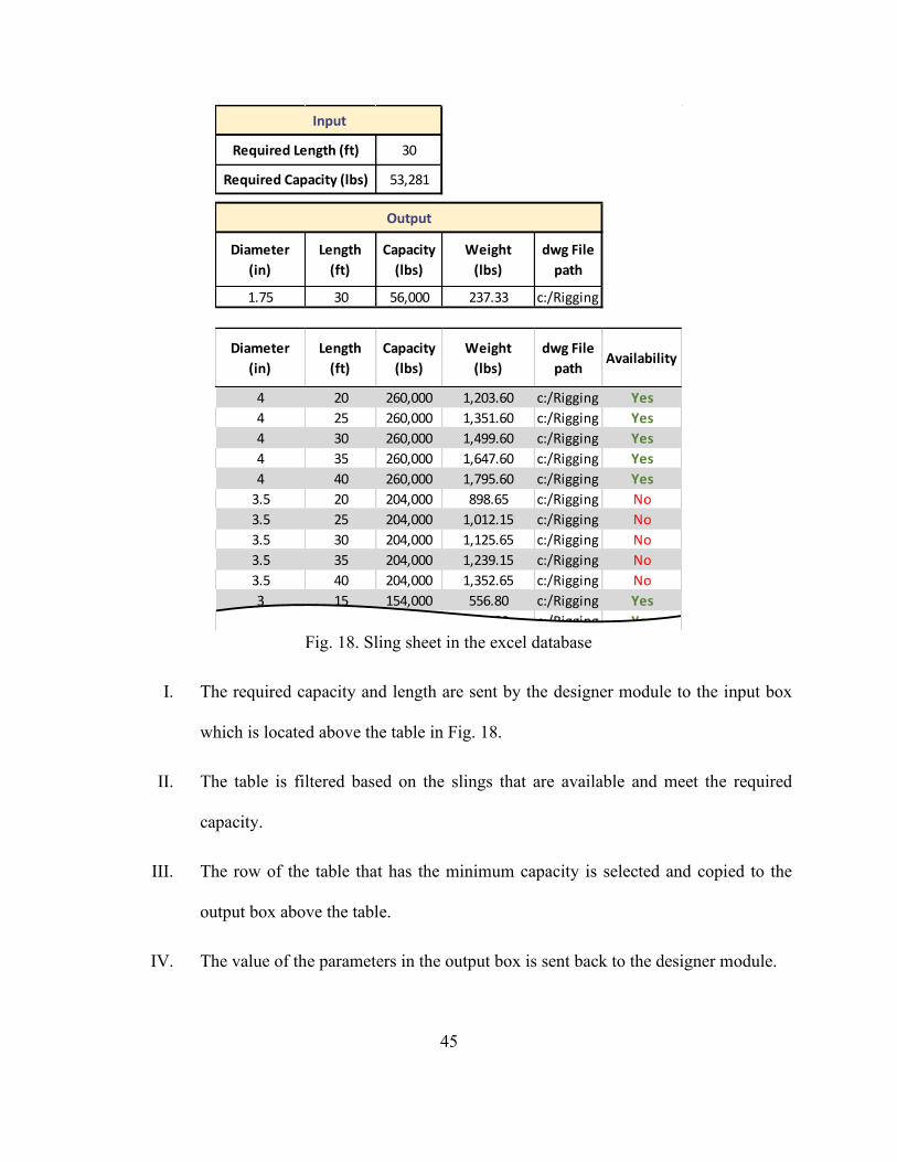
Fig. 18. Sling sheet in the excel database
I. The required capacity and length are sent by the designer module to the input box
which is located above the table in Fig. 18.
II. The table is filtered based on the slings that are available and meet the required
capacity.
III. The row of the table that has the minimum capacity is selected and copied to the
output box above the table.
IV. The value of the parameters in the output box is sent back to the designer module.
30
53,281
Diameter
(in)
Length
(ft)
Capacity
(lbs)
Weight
(lbs)
dwg File
path
1.75 30 56,000 237.33 c:/Rigging Components/G2130sh25
Diameter
(in)
Length
(ft)
Capacity
(lbs)
Weight
(lbs)
dwg File
pathAvailability
4 20 260,000 1,203.60 c:/Rigging Components/G2130sh25Yes
4 25 260,000 1,351.60 c:/Rigging Components/G2130sh25Yes
4 30 260,000 1,499.60 c:/Rigging Components/G2130sh25Yes
4 35 260,000 1,647.60 c:/Rigging Components/G2130sh25Yes
4 40 260,000 1,795.60 c:/Rigging Components/G2130sh25Yes
3.5 20 204,000 898.65 c:/Rigging Components/G2130sh25No
3.5 25 204,000 1,012.15 c:/Rigging Components/G2130sh25No
3.5 30 204,000 1,125.65 c:/Rigging Components/G2130sh25No
3.5 35 204,000 1,239.15 c:/Rigging Components/G2130sh25No
3.5 40 204,000 1,352.65 c:/Rigging Components/G2130sh25No
3 15 154,000 556.80 c:/Rigging Components/G2130sh25Yes
3 20 154,000 639.80 c:/Rigging Components/G2130sh25Yes
Input
Required Capacity (lbs)
Required Length (ft)
Output

46
3.4.4.4 Turnbuckles
The turnbuckles are attached to the drop slings of the 2-point pick segments in order to adjust
the height of this segment. The turnbuckles are selected from the database based on their capacity
and minimum and maximum opening length. The selection process of turnbuckles includes:
Fig. 19. Turnbuckle sheet in the excel database
I. The required capacity and required opening length of the turnbuckle is sent to the
input box which is located above the table in Fig. 19.
II. The “Min. opening length” column of the table is filtered with the values that are less
than the required opening length.
III. The “Max. opening length” column of the table is filtered with the values that are
40.06
20,189
NameWeight
(lbs.)
Max. opening
length (in)
Min. opening
length (in)
Working Load
Limit (lbs)
dwg File
path
1-1/2 x 24 20.70 61.02 38.58 21,407 c:/Rigging Components/1.5x18TB
NameWeight
(lbs.)
Max. opening
length (in)
Min. opening
length (in)
Working Load
Limit (lbs)
dwg File
pathAvailability
2-3/4 x 24 98.00 73.94 51.38 74,957 c:/Rigging Components/2.75x24TBYes
2-1/2 x 24 88.00 72.05 49.37 59,966 c:/Rigging Components/2.5x24TBYes
2 x 24 45.40 65.83 45.31 37,038 c:/Rigging Components/2x24TBYes
1-3/4 x 18 25.00 51.57 36.73 27,999 c:/Rigging Components/1.75x18TBYes
1-3/4 x 24 28.70 63.54 42.68 27,999 c:/Rigging Components/1.75x24TBNo
1-1/2 x 12 16.90 37.05 26.57 21,407 c:/Rigging Components/1.5x12TBYes
1-1/2 x 18 19.30 48.98 32.48 21,407 c:/Rigging Components/1.5x18TBNo
1-1/2 x 24 20.70 61.02 38.58 21,407 c:/Rigging Components/1.5x24TBYes
1-1/4 x 12 11.90 36.06 25.23 15,212 c:/Rigging Components/1.25x12TBYes
1-1/4 x 18 13.60 47.95 31.22 15,212 c:/Rigging Components/1.25x18TBYes
1-1/4 x 24 14.20 60.55 37.83 15,212 c:/Rigging Components/1.25x24TBYes
1 x 6 5.21 21.85 17.60 10,009 c:/Rigging Components/1x6TBNo
Input
Required Opening Length (in)
Required Capacity (lbs)
Output

47
greater than the required opening length.
IV. The unavailable turnbuckles are filtered out using the “Availability” column of the
table.
V. Among the remaining rows of the table, the one that has the minimum capacity is
selected and copied to the output box above the table.
VI. The value of the parameters in the output box is sent back to the designer module.

48
3.5 3D Visualizer Module
The 3D visualizer is developed using an AutoCAD programming interface (API) written in
C# language within the .Net framework. The code uses a nested structure to create a 3D model of
the designed rigging assembly. All of the selected rigging components in the rigging assembly
designer are stored in the database as AutoCAD 3D blocks and are inserted one by one into the
model space and positioned in their suitable coordinates through a sequence of AutoCAD
commands such as copy, move, rotate, etc. The inserted blocks need to be manipulated in order to
correspond to the results of the rigging assembly designer (i.e., length and angle of rigging
components). For instance, the manipulation process for spreader bars, which are equipped with 4
shackles as a 3D block (Fig. 20), includes exploding the block, selecting each of the shackles and
rotating them, selecting the whole block, and moving it to the suitable position. The required
parameters in performing these tasks are collected from both the database and the results of the
rigging analyses. For the spreader bar shown in Fig. 20, α, β, θL, and θR are variable parameters
that are assigned by the results of the solver and designer, while H and SBL are constant values
obtained from the database-stored parameters of the block. These parameters are collected and
used as the inputs of the AutoCAD commands. Fig. 20(a) shows the original configuration of the
block, and Fig. 20(b) shows the manipulated block.
In order to have better control in terms of selecting the rigging components, they are
differentiated with different colors and layers. Thus, the rigging components can be selected using
a selection filter based on the color and the layer that has been assigned to them. Moreover, to
reduce some of the repetitive tasks required in manipulating the inserted blocks, dynamic blocks,
which are designed parametrically and can be modified using their dynamic parameters, are
implemented. For instance, instead of selecting and then rotating a rigging component to a specific

49
angle, a dynamic parameter in conjunction with a rotate action is defined to perform these two
tasks by only assigning an angle to that parameter. Consequently, the parameters of the blocks are
better controlled and the overall execution time of the code is reduced.
(a) (b)
Fig. 20. Constant and variable parameters of a spreader bar block

50
Chapter 4: Case Studies
In order to verify and validate the proposed methodology, the rigging assembly design of
two different modules are used as the case studies. The selected modules are a 6-point pick and a
4-point pick modules. The rigging assembly design and visualization process of these modules
could typically take 1.5 hour in total for an experienced lift engineer. Whereas, using the proposed
methodology, it takes about 10 minutes to accomplish the same series of tasks (including the
potential required manual modifications) with higher accuracy.
A significant amount of time can be saved for each lift study in the planning phase of multi-
heavy lift projects. The methodology has been tested on 50 different modules and no design errors
were encountered. On the other hand, manual designs may involve human errors that lead to
reworks and wasted time, and most importantly may involve safety issues regarding failure of the
rigging components.
4.1 Case Study 1
The first module which is used as case study is an 88,000 lb (39.9 tonne) module that has six
lifting points. The width and length of the module is 376 in (9.55 m) and 209 in (5.31 m),
respectively. The COG is offset from the bottom left corner of the module (P1) by 220 in (5.58 m)
and 84 in (2.13 m) in X and Y directions, respectively. The width of the hook and maximum
acceptable angle of drop slings as input are defined as 17 in (0.43 m) and 3°, respectively, through
the dialogue box shown in Fig. 21. After pressing the “Rigging Analysis” button based on the
available rigging components stored in the Excel database, potential rigging assembly design
alternatives are listed in the “Report” text box located on the right side of the interface. The user
can then create a 3D model for one of the alternatives by pressing the “3D visualization” button.

51
The sequence of design procedures for the rigging assembly, based on the input parameters, is
described in this section.
Fig. 21. The user interface of the proposed methodology
The design of the 4-point pick segment of the rigging assembly begins with designing a
preliminary rigging assembly which is performed by the designer module to provide the initial
values of the known parameters required in task 1 of the solver module. Assuming that the COG
is in the COM, a symmetrical rigging assembly is designed. Table 2 shows the selected rigging
components in the preliminary design.

52
Table 2. Selected rigging components for the preliminary rigging assembly
The sling angles at the first and second levels of the rigging assembly and the RAI are
calculated in a two-dimensional plane containing the spreader bar at the second level and the two
slings above it (represented as the red plane in Fig. 22). By measuring SR, SBL, and SB on the
preliminary rigging assembly and collecting M and ofst from the inputs of the system, the known
parameters are determined: SR = 188 in (4.79 m), SBL = 204 in (5.18 m), SB = 133 in (3.38 m), M
= 209 in (5.31 m), and ofst = 84 in (2.13 m). It should be noted that HW is set to zero for the
calculations at the first and second levels.
Task 1 of the solver is called and the values of sling angles are computed as α = 0.87°, β =
1.29°, θL = 54.33°, and θR = 64.29°. As the drop sling angles (α and β) are smaller than the
maximum acceptable angle (3°) defined by the user, it is not necessary to increase the lengths of
drop slings. The required capacity of the drop slings and the shackles attached to them is calculated
using the designer module as 22,026 lb (9.99 tonne). Then, the suitable drop slings (∅1-1/8 in. ×
10 ft) and shackles, which have a capacity of 12 tonne, are selected from the database. The required
capacity of the spreader bar at the second level is 36,823 lb (16.7 tonne). However, based on
considering the selected sling length (15 ft) at the second level in the preliminary design, there is
Rigging component Description
Shackle at the lifting points 8.5-tonne (inside length = 3.75 in)
Sling length at the first level (drop sling) 10 ft.
Sling length at the second level 15 ft.
Sling length at the third level 25 ft.
Spreader bar length at the second level 17 ft.
Spreader bar length at the third level 31 ft.

53
not a spreader bar available that can meet the required capacity. Therefore, the length of the sling
at the second level is increased to the next longer sling in the database (20 ft) and the value of SR
is updated to 249 in (6.32 m). Task 1 of the solver is called to recalculate the sling angles. With
the updated sling angles (θL = 62.54°, θR = 70.76°), the spreader bar with the length of 204 in (5.18
m) and capacity of 83,600 lb (37.92 tonne) is selected because it satisfies the required capacity.
Based on the required capacity of the slings at level 2, which is 23,326 (10.58 tonne), the suitable
sling (i.e. ∅1-1/8 in × 20 ft) with the capacity of 24,000 lb (10.89 tonne) is selected.
Fig. 22. Calculations of sling angles and RAI in two-dimensional planes
The sling angles at the third level of the rigging assembly and the RAI are calculated in a
HW
M
ofst
SR
SBL
SB
0
209 in.
84 in.
248.75 in
204 in.
133.08 in.
α
β
θL
θR
RAI
0.87°
1.29°
62.54°
70.76°
15.92 in.
HW
M
ofst
SR
SBL
SB
17 in.
376 in.
156 in.
371.86 in
372 in.
368.97 in.
α
β
θL
θR
RAI
0.26°
0.36°
58.69°
66.67°
27.81 in.
Solver
Task 1
Solver
Task 1

54
two-dimensional plane containing the spreader bar at the third level and the two slings above it
(represented as the blue plane in Fig. 22). The known parameters required in Task 1 of the solver
are determined to be HW = 17 in (0.43 m), SR = 312 in (7.92 m), SBL = 372 in (9.45 m), SB = 369
in (9.37 m), M = 376 in (9.55 m), and ofst = 156 in (3.96 m). Based on these inputs, the results of
the solver are α = 0.26°, β = 0.36 °, θL = 52.92°, and θR = 61.82°. Considering the lengths and
angles of slings above the spreader bar, there is not a spreader available that can meet the required
capacity, which is 58,667 lb (26.61 ton). Therefore, the lengths of the slings at level 3 are increased
to the next longer sling in the database (i.e., 30 ft) and the value of SR is updated to 372 in (9.45
m). Consequently, the angles of slings above the spreader bar are increased to θL = 58.69° and θR
= 66.67°. Considering the updated angles, a 372 in (9.45 m) long spreader bar with the capacity of
67,200 lb (30.48 tonne) is selected. The required capacity of the slings at the third level is 37,383
lb (16.96 tonne). Then, the suitable sling (i.e. ∅1-1/2 in × 30 ft) is selected from the database,
which has a 42,000 lb (19.05 tonne) capacity.
As the COG is offset from the COM in both X and Y directions, sling length adjustment is
required at the second and third levels to balance the load. The RAI at the second level and third
level is 15.92 in (40.4 cm) and 27.81 in (70.6 cm), respectively. Therefore, two 35-tonne shackles
that have 15.5 in (39.4 cm) inside length in total are attached to the slings at the second level; and
a combination of one 35-ton and two 55-tonne shackles, which have a total 28.82 in (73.2 cm)
inside length, are added to the sling at the third level.
The design of the 2-point pick segment in the middle of the rigging assembly begins with
calculating the total height of the 4-point pick segment. Based on the selected rigging components,
the height of the 4-point pick segment is 18.67 m. The length of drop slings is set and fixed to the
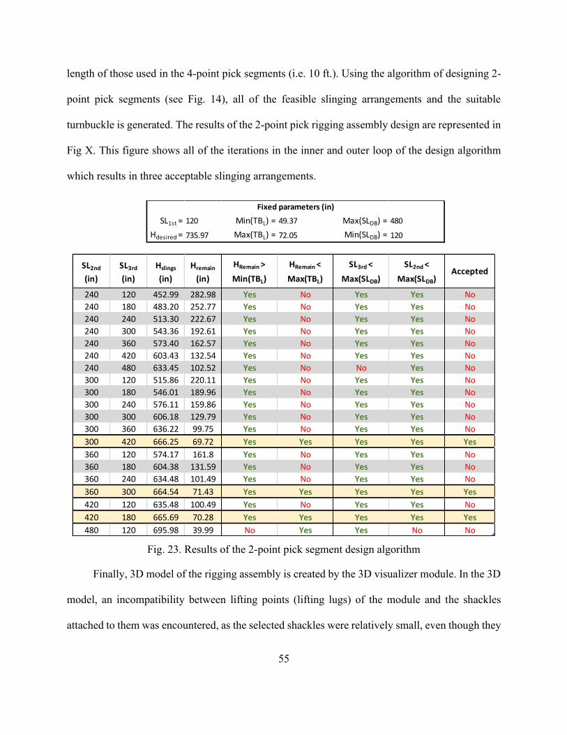
55
length of those used in the 4-point pick segments (i.e. 10 ft.). Using the algorithm of designing 2-
point pick segments (see Fig. 14), all of the feasible slinging arrangements and the suitable
turnbuckle is generated. The results of the 2-point pick rigging assembly design are represented in
Fig X. This figure shows all of the iterations in the inner and outer loop of the design algorithm
which results in three acceptable slinging arrangements.
Fig. 23. Results of the 2-point pick segment design algorithm
Finally, 3D model of the rigging assembly is created by the 3D visualizer module. In the 3D
model, an incompatibility between lifting points (lifting lugs) of the module and the shackles
attached to them was encountered, as the selected shackles were relatively small, even though they
SL1st = 120 Min(TBL) = 49.37 Max(SLDB) = 480
Hdesired = 735.97 Max(TBL) = 72.05 Min(SLDB) = 120
SL2nd
(in)
SL3rd
(in)
Hslings
(in)
Hremain
(in)
HRemain >
Min(TBL)
HRemain <
Max(TBL)
SL3rd <
Max(SLDB)
SL2nd <
Max(SLDB)Accepted
240 120 452.99 282.98 Yes No Yes Yes No
240 180 483.20 252.77 Yes No Yes Yes No
240 240 513.30 222.67 Yes No Yes Yes No
240 300 543.36 192.61 Yes No Yes Yes No
240 360 573.40 162.57 Yes No Yes Yes No
240 420 603.43 132.54 Yes No Yes Yes No
240 480 633.45 102.52 Yes No No Yes No
300 120 515.86 220.11 Yes No Yes Yes No
300 180 546.01 189.96 Yes No Yes Yes No
300 240 576.11 159.86 Yes No Yes Yes No
300 300 606.18 129.79 Yes No Yes Yes No
300 360 636.22 99.75 Yes No Yes Yes No
300 420 666.25 69.72 Yes Yes Yes Yes Yes
360 120 574.17 161.8 Yes No Yes Yes No
360 180 604.38 131.59 Yes No Yes Yes No
360 240 634.48 101.49 Yes No Yes Yes No
360 300 664.54 71.43 Yes Yes Yes Yes Yes
420 120 635.48 100.49 Yes No Yes Yes No
420 180 665.69 70.28 Yes Yes Yes Yes Yes
480 120 695.98 39.99 No Yes Yes No No
Fixed parameters (in)
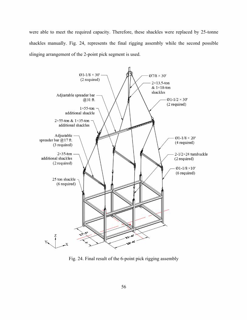
56
were able to meet the required capacity. Therefore, these shackles were replaced by 25-tonne
shackles manually. Fig. 24, represents the final rigging assembly while the second possible
slinging arrangement of the 2-point pick segment is used.
Fig. 24. Final result of the 6-point pick rigging assembly

57
4.2 Case Study 2
The other module which is used as a case study is a 40,000 lb (18.1 tonne) 4-point pick
module with the length of 182 in (4.62 m) and width of 90 in (2.29 m). The COG of the module is
offset from the bottom left corner of the module (P1) by 105 in (2.67 m) and 60 in (1.52 m) in X
and Y direction, respectively. As shown in Fig. 25 the width of the hook and the maximum
acceptable drop sling angle is determined by the user as 17 in (0.43 m) and 1.5°.
Fig. 25. The user interface of the proposed methodology
Assuming that the COG is at the center of module, a preliminary rigging assembly is deigned
by the designer module to provide the input data for the solver module. The selected rigging
components of the preliminary rigging assembly are shown in Table 3.

58
Table 3. Selected rigging components for the preliminary rigging assembly
In order to calculate the angle of slings attached to the spreader bar at level 2 (represented as
the red plane in Fig. 26), based on the preliminary design and inputs of the system, the initial value
of SR, SBL, M, ofst, and HW as the known parameters of the solver module is determined as SR =
128.75 in (3.27 m), SBL = 96 in (2.44 m), SB = 132 in (3.35 m), M = 90 in (2.29 m), ofst = 30 in
(0.76 m), and HW = 0. By calling task 1 of the solver module, the sling angles are computed as α
= 0.9°, β = 1.7°. Since the maximum acceptable drop sling angle (1.5°) is not satisfied, the drop
slings are increased by 5 ft. (length interval of the slings in the database). The solver module is
called to recalculate the sling angles using the update input data. The updated value of input and
output parameters is shown in Fig. 26.
Rigging component Description
Shackle at the lifting points 4.75-tonne (inside length = 2.81 in)
Sling length at the first level (drop sling) 10 ft.
Sling length at the second level 10 ft.
Sling length at the third level 15 ft.
Spreader bar length at the second level 8 ft.
Spreader bar length at the third level 15 ft.

59
Fig. 26. Calculations of sling angles and RAI in two-dimensional planes
Based on the sling angles and the amount of weight at the lifting points, the required capacity
of the shackles at the lifting points, drop slings, spreader bar, and the slings at level 2 are calculated
and the suitable slings and spreader bar are selected from the database as shown in Table 4. It
should be noted that, the selected sling length in the preliminary design is long enough for the
required capacity of the spreader bar and there is no need to increase the length of sling in order to
gain higher capacity of the spreader bar.
Similarly, the angle of slings located at the third level of the rigging assembly are calculated
by the solver module in the plain containing the spreader bar at this level (represented as the blue
plain in Fig. 26). Therefore, based on the computed sling angles, the required capacity of slings
and spreader bar at level is determined and the suitable slings and spreader bar is selected from the
HW
M
ofst
SR
SBL
SB
0
90 in.
30 in.
128.75 in
96 in.
192 in.
α
β
θL
θR
RAI
0.60°
1.19°
62.8°
75.6°
11.45 in.
Solver
Task 1
HW
M
ofst
SR
SBL
SB
17 in.
182 in.
77 in.
188.75 in
180 in.
317.77 in.
α
β
θL
θR
RAI
0.15°
0.21°
68.6°
61.8°
10.54 in.
Solver
Task 1

60
database as shown in Table 4.
Table 4. the required and rated capacity of the selected rigging components
In order to balance the module in both X and Y direction, additional shackles are required to
be added above the spreader bars at both level two and three. The RAI at level two is calculated
by task 2 of the solver module as 11.45 in (29.1 cm). So, two 17-tonne shackles which have 11.5
in (29.2 cm) inside length in total are mounted above the spreader bar at level two to balance the
module in Y direction. The RAI at level three is calculated as 10.54 in (26.8 cm). Therefore, a 55-
tonne shackle which has 10.5 in (26.7 cm) inside length is mounted to above the spreader bar at
level three to balance the load in X direction. Fig. 27, represents the final 3D model of the rigging
assembly.
Rigging component Required capacity Rated capacity
Shackles at the lifting points 6.98 tonne 8.5 tonne
Sling at the first level 15,385 lb (6.98 tonne) 19,600 lb (8.89 tonne)
Sling at the second level 15,882 lb (7.2 tonne) 19,600 lb (8.89 tonne)
Sling at the third level 24,790 lb (11.24 tonne) 30,000 lb (13.61 tonne)
Spreader bar at the second level 23,077 lb (10.47 tonne) 92,400 lb (41.91 tonne)
Spreader bar at the third level 40,000 lb (18.14 tonne) 87,400 lb (39.64 tonne)

61
Fig. 27. Final result of the 4-point pick rigging assembly

62
Chapter 5: Future Works
The proposed methodology is subject to some limitations and requires further development.
The current system uses an Excel database which not only is prone to accidental changes to data
while developing the database but also makes the automated system relatively slows. These issues
therefore could be addressed by developing a SQL database which is faster and more maintainable.
Another limitation of the current system is that the module information (i.e. weight,
dimensions, center of gravity position) is required to be entered by the user manually. Considering
that the number of modules in major refinery projects may reach over 100, manually entering
information for each module and then running the system for each individual one could be a tedious
and prolonged process. A better approach in regards of this issue could be creating a database of
modules information and developing the proposed system in a way to collect the information from
the modules database to automatically design and visualize the rigging assembly for the entire
modules. In this context, implementing Building Information Modelling (BIM) process could also
be considered as further development of the framework. Using BIM tools, the modules and the
rigging assemblies can be managed and designed in an integrated environment. In that case, other
parameters such as scheduling and cost could be factored in for making decisions in the design
and planning phase of the lifting projects.
The current system selects the same rigging components at each level of the rigging assembly
since only the maximum load at each level is considered as the required capacity. Therefore, the
output of the system is an over designed rigging assembly. In this context, structural analysis could
be implemented in the future works in order to determine the actual forces applied to each rigging
component and select the suitable rigging components according to the actual required capacity.

63
As it was explained in the 2-point pick segments, in the current system, the design
alternatives are generated by changing the length of slings at different levels of the configuration
in a nested loop and the final decision is to be made by the user to use one of the design alternatives.
This issue could be addressed by optimizing the design process so that only one rigging assembly
is generated which is the optimal one. The optimization objectives could be the weight of the
rigging assembly, used capacity of the rigging components and the way that the load is distributed
throughout the segment.
The heights of lifting points on some modules are not in the same elevation. In designing the
rigging assembly for those modules, the sling length at the first level needs to be adjusted to bring
all of the lifting points to the same elevation. Also, for some modules, especially those which are
lifted from the bottom and their lifting points are installed on their beams, vertical lift may not be
essential. Therefore, for those modules inclined slings are used at the first level of their rigging
assembly. The current system cannot be used to design the rigging assembly of the aforementioned
modules.

64
Chapter 6: Conclusion
Prior to lifting heavy modules at industrial sites, crane lift studies including crane selection,
crane location, crane support system, rigging assembly design, and crane motion planning are
essential to ensure that the modules are lifted and erected safely and efficiently. As one of the main
components of a crane lift study, the rigging assembly design involves tedious, complex, and time-
consuming tasks such as calculating the sling angles, determining the required capacity of the
rigging components, selecting suitable rigging components, and creating the 3D model of the
designed rigging assembly. These tasks become more complicated when the module’s center of
gravity is offset from the center of module. Rigging assemblies are required to be designed in a
way to ensure that the modules are lifted vertically and maintained in a level position during the
lift. Lifting modules unevenly increases the risk of module tilting and deflection, and, more
importantly, the risk of rigging failure as a result of unexpected distribution of the load throughout
the rigging assembly. Poorly designed rigging assemblies are only detected at the job site when
the module does not raise evenly at the beginning of the lift, which results in wasted time and
productivity loss, as the assembled components have to be unrigged and properly adjusted. In this
respect, this thesis has proposed an automated mathematical-based rigging assembly design system
to assist lift engineers by automating the design and visualization of rigging assemblies. The
proposed framework consists of the following three elements: (i) the solver, which performs two
tasks: calculating the sling angles at each level of the rigging assembly through solving a system
of nonlinear equations, and finding the optimal size and number of shackles that are attached to
slings to increase their lengths; (ii) the designer, which calculates the required capacity of the
rigging components based on the module information and selects suitable rigging components that

65
meet the required capacity from the database considering their availability; and (iii) the 3D
visualizer, which creates a 3D model of the rigging assembly in the AutoCAD platform to identify
whether the selected rigging components can be properly assembled in real life. A 6-point pick
and a 4-point pick module were used as a case study to demonstrate the validity and effectiveness
of the proposed framework. Also, the framework was tested on 50 modules, which resulted in
saving almost 42 hours (50 minutes per module) in total and eliminating manual design errors,
which can happen at a rate of approximately 5 to 10%.

66
References
[1] G. P. Burke, R. C. Miller, Modularization speeds construction, Power Engineering 102 (1)
(1998) 20–23.
[2] L. Westover, J. Olearczyk, U. Hermann, S. Adeeb, Y. Mohamed, Analysis of rigging assembly
for lifting heavy industrial modules, Canadian Journal of Civil Engineering 41 (6) (2014) 512–
522.
[3] J. Olearczyk, Z. Lei, B. Ofrim, S. Han, M. Al-Hussein, Intelligent crane management
algorithm for construction operation, proceedings, International Association for Automation
and Robotics in Construction (IAARC), Oulu, Finland, 2015, pp. 1-8.
[4] H. Taghaddos, U. Hermann, A. Abbasi, Automated crane planning and optimization for
modular construction, Automation in Construction 95 (2018) 219–232.
[5] C.-S. Cho, F. Boafo, Y.-J. Byon, H. Kim, Impact analysis of the new OSHA cranes and derricks
regulations on crane operation safety, KSCE Journal of Civil Engineering 21 (1) (2016) 54–
66.
[6] J. Olearczyk, M. Al-Hussein, A. Bouferguene, Evolution of the crane selection and on-site
utilization process for modular construction multilifts, Automation in construction 43 (2014)
59–72.
[7] S. Han, S. Hasan, A. Bouferguene, M. Al-Hussein, J. Kosa, An integrated decision support
model for selecting the most feasible crane at heavy construction sites, Automation in
Construction 87 (2018) 188–200.
[8] D. Wu, Y. Lin, X. Wang, X. Wang, S. Gao, Algorithm of crane selection for heavy lifts, Journal
of Computing in Civil Engineering 25 (1) (2011) 57–65.

67
[9] Y. Lin, H. Yu, G. Sun, P. Shi, Lift path planning without prior picking/placing configurations:
Using crane location regions, Journal of Computing in Civil Engineering 30 (1) (2014)
04014109.
[10] S. Han, Z. Lei, A. Bouferguene, M. Al-Hussein, U. Hermann, 3d visualization-based
motion planning of mobile crane operations in heavy industrial projects, Journal of Computing
in Civil Engineering 30 (1) (2014) 04014127.
[11] Z. Lei, S. Han, A. Bouferguene, H. Taghaddos, U. Hermann, M. Al-Hussein, Algorithm
for mobile crane walking path planning in congested industrial plants, Journal of Construction
Engineering and Management 141 (2) (2014) 05014016.
[12] H. R. Reddy, K. Varghese, Automated path planning for mobile crane lifts, Computer-
Aided Civil and Infrastructure Engineering 17 (6) (2002) 439– 448.
[13] Z. Lei, H. Taghaddos, S. Han, A. Bouferguene, M. Al-Hussein, U. Hermann, From
AutoCAD to 3ds max: An automated approach for animating heavy lifting studies, Canadian
Journal of Civil Engineering 42 (3) (2015) 190–198.
[14] S. H. Han, S. Hasan, A. Bouferguene, M. Al-Hussein, J. Kosa, Utilization of 3d
visualization of mobile crane operations for modular construction on-site assembly, Journal of
Management in Engineering 31 (5) (2014) 04014080.
[15] S. Han, A. Bouferguene, M. Al-Hussein, U. R. Hermann, 3d-based crane evaluation system
for mobile crane operation selection on modular-based heavy construction sites, Journal of
Construction Engineering and Management 143 (9) (2017) 04017060.
[16] H. Taghaddos, A. Eslami, U. Hermann, S. AbouRizk, Y. Mohamed, Auction-based
simulation for industrial crane operations, Automation in Construction 104 (2019) 107–119.

68
[17] K. D. Roy, A. K. Dev, S. Aksu, Installation engineering of topside modules on ship shaped
offshore floating structures, Advanced Maritime Engineering Conference (AMEC), Singapore,
2010.
[18] Anderson J. K. Rigging Engineering Basics, 1(1), ITI Bookstore, Woodland, Washington
98674, (2013).
[19] The Crosby Group LLC. Crosby General Catalogue. 2801 Dawson Rd., Tulsa, OK 74110,
(2017).
[20] M.-T. Sam, Offshore heavy lift rigging analysis using spreadsheet, Practice Periodical on
Structural Design and Construction 14 (2) (2009) 63–69.
[21] R. Longman, F. Freudenstein, Stability analysis of lifting rigs part 1: Necessary and
sufficient conditions, Journal of Engineering for Industry 97 (2) (1975) 532–536.
[22] P.-Y. Chen, Z.-Y. Zhuang, C.-M. Chang, S.-C. Kang, A numerical model for the attitude
manipulation of twin-hoisted object, Proceedings, International Association for Automation
and Robotics in Construction (IAARC), Berlin, Germany, 2018, pp. 219-223.
[23] K.-L. Lin, C. T. Haas, Multiple heavy lifts optimization, Journal of construction
engineering and management 122 (4) (1996) 354–362.
[24] C. Bennett, S. Ditlinger, Bechtel automated lift planning system, in: Robotics for
challenging environments, (19)94, p. 401.
[25] K. Varghese, P. Dharwadkar, J. Wolfhope, J. T. O’Connor, A heavy lift planning system
for crane lifts, Computer-Aided Civil and Infrastructure Engineering 12 (1) (1997) 31–42.
[26] 3D Lift Plan software, A1A software LLC, < http://www.a1asoftware.net/about.html>,
Accessed date: May, 2019.

69
[27] CRANEbee Software, CRANIMAX Software development and distribution company,
<https://www.cranimax.com/> Accessed date: May, 2019.
[28] kranXpert software, Markus Scholl, < https://www.kranxpert.de/>, Accessed date: May,
2019.
[29] S. Hashemi, S. Han, J. Olearczyk, A. Bouferguene, M. Al-Hussein, J. Kosa, Automated
mathematical-based design framework for the selection of rigging configuration, Proceedings,
International Association for Automation and Robotics in Construction (IAARC), Banff,
Canada, 2019, pp. 172-178.