automated advantg variance reduction in a proton … · kenneth a. van riper1 and robert l....
TRANSCRIPT

M&C 2017 - International Conference on Mathematics & Computational Methods Applied to Nuclear Science & Engineering,Jeju, Korea, April 16-20, 2017, on USB (2017)
Automated ADVANTG Variance Reduction in a Proton Driven System
Kenneth A. Van Riper1 and Robert L. Metzger2
1White Rock Science, P. O. Box 4729, White Rock, NM 87547, [email protected] Safety Engineering, 3245 N. Washington, Chandler, AZ 85225, [email protected]
Abstract – We discuss the use of the ADVANTG automated variance reduction program for shieldingstudies of a vault containing targets irradiated by cyclotron accelerated protons. Because ADVANTG islimited to neutron and photon models, our calculations proceeded in several steps. Neutrons and photonsemanating from a sphere surrounding the target were saved to a surface source file. This file was used todefine sources for the ADVANTG runs and as a source for subsequent Monte Carlo runs. Test runs weremade to ensure the validity of each step. The final calculations using the ADVANTG produced weightwindows ran much more quickly and gave the same results as a model using only importance splitting forvariance reduction.
I. INTRODUCTION
We recently completed a shielding design for acyclotron vault on the Mayo Clinic's Scottsdale, AZ campus[1]. That work used Monte Carlo calculations by MCNPX,version 2.7 [2] to evaluate the neutron and photon transportthrough the 1.83 m (6') thick concrete walls and ceiling andstreaming through the entrance maze. Variance reduction isrequired to calculate penetration of the thick concretebarriers and to direct the radiation through the maze. Weused the technique of importance splitting with 26importance layers through the walls and 31 layers betweenthe source and the entrance.
More recently, we were commissioned to evaluate theshielding of a similar cyclotron vault. For this work, we
used the MCNP6, version 6.1 [3] Monte Carlo code and theADVANTG [4] code to calculate Weight Windows (WWs)to be used for variance reduction. Because ADVANTG isonly applicable to neutron and photon transport and not tothe cyclotron's proton beam impinging on a target, severalsteps were necessary. In the first stage, the neutrons andphotons crossing a sphere surrounding the target werewritten to an MCNP surface source (SS) file. Neutron andphoton tallies on that sphere were converted to sources forthe ADVANTG calculations. The resulting neutron andphoton weight windows were merged and used in the finalMCNP6 runs with the surface source read (SSR) feature. Anumber of test calculations were made to check the validityof some approximations and to resolve a discrepancyinitially found between the MCNP6 and MCNPX results.
Fig. 1. Monte Carlo model (red) overlaid on architectural drawing.

M&C 2017 - International Conference on Mathematics & Computational Methods Applied to Nuclear Science & Engineering,Jeju, Korea, April 16-20, 2017, on USB (2017)
II. DESCRIPTION OF THE ACTUAL WORK
1. Cyclotron Vault Model
The vault houses a General Electric cyclotron. Theprimary use is production of 18F for PET imaging. The PETisotopes are produced in a target adjacent to the accelerator.The proton beam can be directed to an external target in anadjoining room for production of other clinical and researchisotopes including 11C, 13N, 15O, 63Zn, and 68Ga. We refer tothe former as the cyclotron target and the latter as theexternal target.
A. Geometry
Figure 1 shows a floor plan of the model overlaid on anarchitectural drawing of the building. Thick red lines outlinethe Monte Carlo regions except for the interior and exteriorair spaces. From south to north (left to right in Fig. 1), themodel consists of the entrance maze, the cyclotron roomcontaining the cyclotron target and collimator material, andthe external target room with the external target. Alsoshown in red are the outlines of the targets and thecollimator. The concrete walls and ceiling are 1.83 m (6')thick. The ceiling height within the vault is 3.048 m (10”).The concrete floor is 0.9144 m (3”) thick. An air spaceapproximately 1.1 m (3 ½”) thick surrounds the vault abovefloor level.
The model includes a door at the maze entrance and anintermediate door in the middle of the maze. Both doors area slab of 2.54 cm (1”) borated polyethylene. The entrancedoor also has a 0.3175 cm (⅛”) layer of lead on the outside.The air space in the maze above the 2.286 m (7 ½”) doorheight is filled with three air ducts surrounded by copper.Copper was chosen as an approximate model of the electriccables running through the space. The duct dimensions(25.4 cm [10”] wide by 53.45 cm [21”] high) were chosenso that the overhead space contains ½ air and ½ copper byvolume.
The targets consist of a 75 μm havar foil over a vacuumtube leading to 18O enriched water in a silver holder, allcontained in an aluminum housing with a stainless steelbacking plate. The collimator is modeled as a graphite blockslightly offset from the target beam line.
B. Sources
The cyclotron produces a beam of 16.5 MeV protons.The maximum current used in the cyclotron room is 130 μAafter a 10% loss upon passing through the collimator. The130 μA is split between into 65 μA on two targets. For theMonte Carlo model, we use 130 μA on a single target. Wealso assume a fully irradiated (double) target emitting 2 x3500 mCi of 0.511 MeV photons. The total (proton beam +photons) rate of particle emission is 8.927 x 10¹⁴ / second.
The target room model assumes a 80 μA proton beamimpinging on the external target, a 8 μA beam loss on thecollimator in the cyclotron room, and single 3500 mCi loadof irradiated target material. The total rate of particleemission is 5.493 x 10¹⁴ / second.
Two proton beams are directed directed northward (tothe right in Fig. 1) with a small divergence angle. The beamorigins are just downstream of the respective target and thecollimator. The photons are emitted isotropically. Thephoton source is distributed uniformly throughout the targetwater (H2 18O) volume.
C. Mesh Tallies
Fig. 2. Mesh tally locations in a 3-dimensional view.
Mesh tallies record the dose equivalent rate and itsrelative error (RE) on a spatial grid of mesh cells. Doseresponse functions were used to convert the flux to a doserate. For neutrons, the response function was taken fromNCRP-38 1971, ANSI/ANS 6.1.1—1977. The QualityFactors in the NCRP-38 dose response function match thoselisted in 10 CFR Part 20. For photons, the values in ICRP-21 1971 were used.
Four mesh tallies were used. They are shown in Figure2. The horizontal red, north-south blue, and east-west greenmesh tallies pass through the location of the cyclotrontarget. For external target irradiation, the green mesh tally ismoved to pass through that target. The yellow (or tan) meshtally covers the exterior of the south wall. This region is ofinterest because of the maze entrance and an operator'sconsole east of (to the right in fig. 2) the entrance door.
Each mesh tally has one grid cell in the short direction(e. g. in the Z or up direction for the red horizontal tally) oflength 50 cm (99 cm for the yellow south wall tally). Thegrid cell dimensions are 5 cm (10 cm for the south walltally) in the other directions (e. g. X and Y for the red tally).

M&C 2017 - International Conference on Mathematics & Computational Methods Applied to Nuclear Science & Engineering,Jeju, Korea, April 16-20, 2017, on USB (2017)
2. Preliminary Considerations
A. Proton Transport
The previous work enabled proton transport throughoutthe model. Some protons were scattered from the target andcollimator, but very few of these reached the walls andceiling. Secondary protons were produced by interactionswithin the concrete. Except in the target, collimator, andclose surrounding air, the proton contribution to the doseequivalent rate was much smaller than the neutron andphoton contributions. To verify that proton transport couldbe neglected in the concrete, we compared the results fromtwo models with and without proton transport enabledwithin the walls and ceiling. The external neutron andphoton dose rates were the same in both cases, showing thatproton transport can be neglected in the SSR runs. Themodels with limited proton transport ran 1.7% and 16%more quickly under MCNPX and MCNP6, respectively.
B. MCNP6 & MCNPX Comparison
Our initial calculations with MCNP6 showed a muchlower external neutron dose rate than with MCNPX. Thediscrepancy increased from the source through the walls.We traced the cause to the material definitions. Mostmaterial constituents were defined as elements in the initialmodels. When the elemental fractions were divided amongthe naturally occurring isotopes of the element, the MCNP6and MCNPX results came into agreement. We used isotopicmaterial definitions in succeeding models.
Fig. 3. Neutron dose equivalent rate from wall to wall through the cyclotron target for different options.
Figure 3 shows profiles of the neutron dose equivalentrate from wall to wall passing through the cyclotron target(bottom to top in Fig. 1) for the two codes using elemental
and isotopic material definitions. All agree except for theMCNP6 model with elemental material definitions (black).
3. Surface Source Write
Fig. 4. Outlines of the target and collimator models (red) and surface source spheres (green) overlaid on the architectural drawing.
To take advantage of the multi-threading capability ofMCNP6 when calculating a model transporting onlyneutrons and photons and to prepare sources for theADVANTG code, we proceeded in two steps. In the firststep, protons irradiated the target and collimator. Theresulting neutrons and photons outwardly crossing a spheresurrounding the target(s) were saved to a file using theMCNP Surface Source Write (SSW) feature. Two SSWruns were made, one for each source location. Eachfollowed 5 x 10⁸ source protons. The cyclotron target SSWmodel included only the air in the room surrounding thetarget and collimator. The external target SSW modelincluded air around the external target and collimator and aportion of the stub wall between the two rooms and wroteparticles crossing both spheres. Figure 4 shows the locationof the surface source spheres.
4. ADVANTG Models
The ADVANTG (AutomateD VAriaNce reducTionGenerator) code from Oak Ridge National Laboratorycalculates energy dependent WWs on a spatial grid coveringthe model. The WWs control the population of particles inthe grid cells, ensuring a sufficient population for adequatesampling while preventing local over populations thatincrease computation time. The FW–CADIS (Forward-Weighted–Consistent Adjoint Driven Importance Sampling)method optimizes the WWs for low REs in each mesh tallycell. Except for the items noted here, default values wereused for all options.

M&C 2017 - International Conference on Mathematics & Computational Methods Applied to Nuclear Science & Engineering,Jeju, Korea, April 16-20, 2017, on USB (2017)
Fig. 5. Neutron dose equivalent rates (top) and relative errors (bottom). Dimensions are in feet.

M&C 2017 - International Conference on Mathematics & Computational Methods Applied to Nuclear Science & Engineering,Jeju, Korea, April 16-20, 2017, on USB (2017)
Fig. 6. Photon dose equivalent rates (top) and relative errors (bottom). Dimensions are in feet.

M&C 2017 - International Conference on Mathematics & Computational Methods Applied to Nuclear Science & Engineering,Jeju, Korea, April 16-20, 2017, on USB (2017)
A, Spatial Grid
ADVANTG executes the Denovo discrete ordinatestransport code on a Cartesian mesh overlaying the MonteCarlo model. We specified the grid using the X, Y, and Zplane coordinates of every plane in the Monte Carlo model,including the planes introduced previously for importancesplitting. Except for the target models that are not used inthe ADVANTG model, all geometry is defined by alignedplanes. Because the Denovo grid contained all materialboundaries, no mixed material cells were present.
B. Source Terms
Because the surface source is incompatible withADVANTG, we converted neutron and photon surfacetallies on a sphere(s) just outside of the surface sourcesphere(s) to a point source(s) at the center of the sphere(s).Each tally contained 200 energy bins. The point sourceweight for each component is the total value of the tally.
Comparison of test runs of the Monte Carlo modelusing the point source and the SSR source gavesubstantially identical results, showing that the point sourcewas correctly defined and is adequate for use in theADVANTG model.
C. Merging Weight Window Files
ADVANTG executes MCNP5 [5] to parse the MonteCarlo model. Because the MCNP5 source is restricted to asingle particle type, a mixed neutron-photon source cannotbe used. Instead, ADVANTG was run separately forneutrons and photons from the surface source. SeparateADVANTG calculations were made for irradiation of thecyclotron target and the external target.
The WWs are written to the file WWINP. The twoWWINP files were manually merged with a text editor. Thefile consists of two header lines, the spatial grid, and thenthe WW data. The second line gives the number of neutronand photon energy bins. To merge, change the 0 for thenumber of photon energy bins in the neutron WWINP fileto the value from the photon file, delete the header andspatial grid section from the photon file and append it to theneutron WWINP file. A comparison of the two files willshow where the identical spatial grid section ends.
III. RESULTS
Four MCNP6 calculations using the ADVANTG WWswere made: with and without an intermediate maze door foreach of the cyclotron and external target sources. Figures 5and 6 show the neutron and photon dose equivalent ratesand REs in the horizontal mesh tally for the cyclotron targetmodel with the intermediate door. Except for small regionsof low neutron dose rate near the vault corners, all REs are ≤0.1, indicating valid results. The other models gave similar
good results. The linear regions of higher photon RE at theleft and right edges are due to a small number of highenergy source photons.
Reading once through the SS file resulted in theprocessing of 3.3x10⁶ histories requiring approximately 12hours of wall clock time when running with 14 threads. Acomparison run using importance splitting, rather than theADVANTG WWs, was terminated after 6 days of runningwith 40 threads, having processed only 0.85x10⁶ histories.Similar dose rates obtained but with much larger REs.Figure 7 compares the cumulative photon and neutron REsfor each of the variance reduction methods. The curvesshow the fraction of mesh tally cells with REs less than orequal to the RE on the abscissa. The default output from theSSR runs does not list the Figure of Merit (FOM), so acomparison of the FOMs is not possible.
Fig. 7. Fraction of mesh tally cells with RE less than or equal to the RE on the abscissa.
A. Attenuation Through the Doors
Figure 8 shows the total, neutron, and photon doseequivalent rates along a south to north path passing throughthe center of the intermediate door position (x = 10 feet).Two sets of curves compare the profiles with and withoutthe 2.54 cm borated polyethylene door for irradiation of thecyclotron target. The total and neutron dose rates drop by afactor of 5 passing through the intermediate door. The doordoes not attenuate the photon dose. Similar reductionsobtain for external target irradiation.
Neutrons dominate the total dose equivalent rate in theinterior of the vault. The steep decline between x = 3 feetand x = 0 occurs in the southernmost concrete barrier.Photons dominate the total dose equivalent rate exterior tothe vault.
Figure 9 shows the total, neutron, and photon doseequivalent rates along a south to north path passing throughthe center of the entrance door (x = 0) for the case of
M&C 2017 - International Conference on Mathematics & Computational Methods Applied to Nuclear Science & Engineering,Jeju, Korea, April 16-20, 2017, on USB (2017)
cyclotron target irradiation with an intermediate door. Theneutron, photon, and total dose rates decrease by factors of7, 2, and 3.5, respectively, through the entrance door.Similar reductions obtain for external target irradiation andin the models without an intermediate door.
Fig. 8. Dose equivalent rate profiles along a south-north path through the intermediate door position.
Fig. 9. Dose equivalent rate profiles along a south-north path through the entrance door.
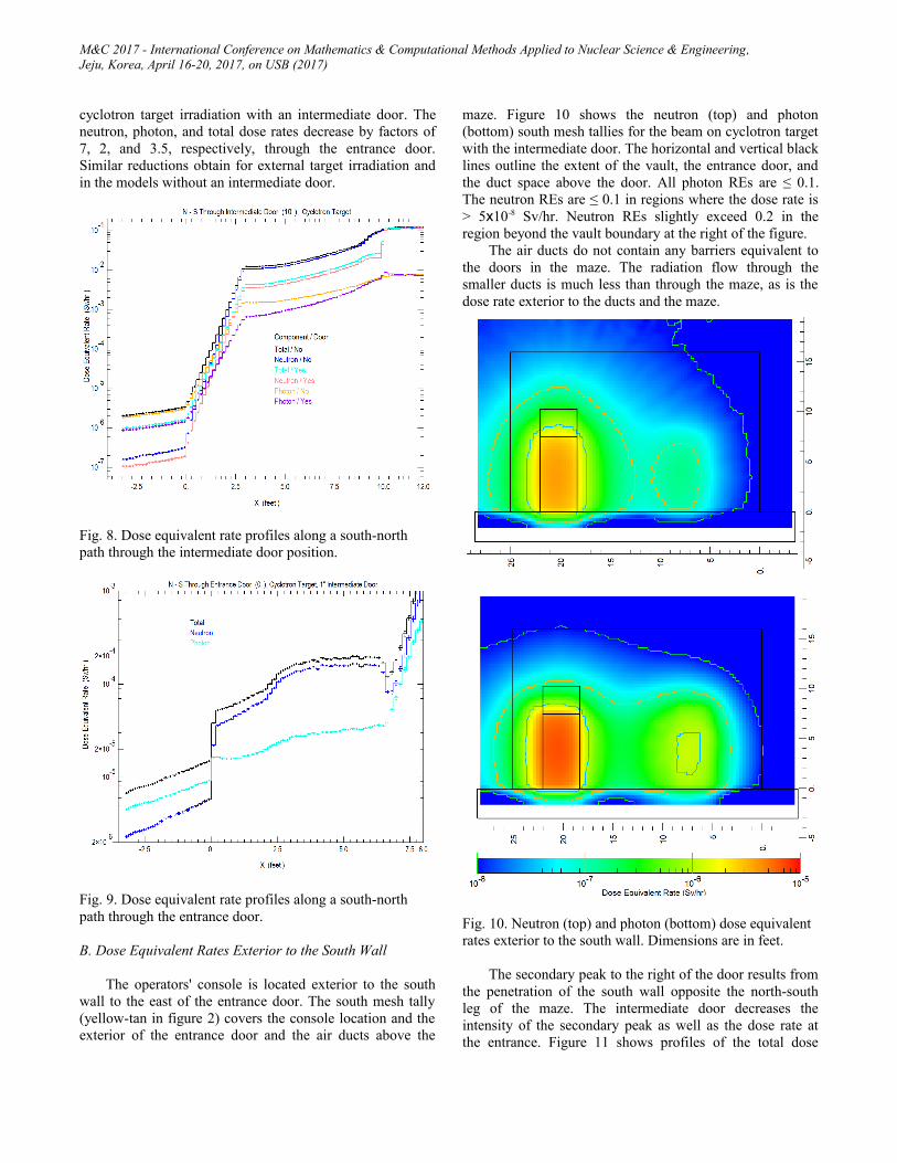
B. Dose Equivalent Rates Exterior to the South Wall
The operators' console is located exterior to the southwall to the east of the entrance door. The south mesh tally(yellow-tan in figure 2) covers the console location and theexterior of the entrance door and the air ducts above the
maze. Figure 10 shows the neutron (top) and photon(bottom) south mesh tallies for the beam on cyclotron targetwith the intermediate door. The horizontal and vertical blacklines outline the extent of the vault, the entrance door, andthe duct space above the door. All photon REs are ≤ 0.1.The neutron REs are ≤ 0.1 in regions where the dose rate is> 5x10⁻⁸ Sv/hr. Neutron REs slightly exceed 0.2 in theregion beyond the vault boundary at the right of the figure.
The air ducts do not contain any barriers equivalent tothe doors in the maze. The radiation flow through thesmaller ducts is much less than through the maze, as is thedose rate exterior to the ducts and the maze.
Fig. 10. Neutron (top) and photon (bottom) dose equivalent rates exterior to the south wall. Dimensions are in feet.
The secondary peak to the right of the door results fromthe penetration of the south wall opposite the north-southleg of the maze. The intermediate door decreases theintensity of the secondary peak as well as the dose rate atthe entrance. Figure 11 shows profiles of the total dose

M&C 2017 - International Conference on Mathematics & Computational Methods Applied to Nuclear Science & Engineering,Jeju, Korea, April 16-20, 2017, on USB (2017)
equivalent rate from east to west (right to left in fig. 10) at ½the maze height in the south mesh tally. Results are from all4 models (cyclotron/external target with and without theintermediate door) considered. The intermediate door resultsin a factor 2 reduction in the external dose rate at both theentrance and the secondary peak.
Fig. 11. Total dose equivalent rate profiles along an east to west path exterior to the south wall.
IV. CONCLUSIONS
We have successfully applied WWs calculated byADVANTG to a model with a proton beam source. The useof these WWs resulted in a significant reduction of MCNP6calculation time, even with the additional steps required,compared with variance reduction by importance splitting.The resulting small errors permit meaningful comparisonsof the external dose equivalent rates among the differentmodels studied.
ACKNOWLEDGMENT
We thank the cyclotron team at the Jacksonville Floridacampus of the Mayo Clinic for their support of this work.
REFERENCES
1. K. A. VAN RIPER, R. L. METZGER, and K. NELSON, “Shielding Design of the Mayo Clinic Scottsdale Cyclotron Vault,” Proc. Joint 13th International Conference on Radiation Shielding & 19th Topical Meeting of the Radiation Protection and Shielding Division of the ANS ICRS-13 & RPSD-2016, Paris, France, October 3-6, 2016.
2. D. PELOWITZ (ed.), “MCNPX User’s Manual, Version2.7.0,” Los Alamos National Laboratory, LA–CP–11–00438 (2011).
3. D. B. PELOWITZ, A. J. FALLGREN, G. E. MCMATH. “MCNP6 User's Manual, Code Version 6.1.1beta,” Los Alamos National Laboratory, LA–CP–14–00745, Rev. 0, (2014).
4. W. MOSHER, et. al, “ADVANTG - An Automated Variance Reduction Parameter Generator,” ORNL/TM–2013/416 Rev. 1, Oak Ridge National Laboratory, Oak Ridge, TN, (2015).
5. Los Alamos Monte Carlo Group, "MCNP-A General Monte Carlo N-Particle Transport Code Version 5," Vols. I-III, Los Alamos National Laboratory, LA-UR-03-1987 (2003).