automate application deployment with f5 local traffic ... · © 201 6 cisco | f5 networks. all...
TRANSCRIPT

© 2016 Cisco | F5 Networks. All rights reserved. Page 1
Automate Application Deployment with F5 Local Traffic Manager and
Cisco Application Centric Infrastructure
White Paper

© 2016 Cisco | F5 Networks. All rights reserved. Page 2
Contents
What You Will Learn ................................................................................................................................... 3 Document Scope ...................................................................................................................................... 3
Solution Overview ....................................................................................................................................... 3 Traditional Layer 4 through 7 Service Insertion Challenges ..................................................................... 3 Automated Layer 4 through 7 Service Insertion Using Cisco APIC ......................................................... 4 Why F5 BIG-IP LTM Integration with Cisco ACI ....................................................................................... 4 Joint Solution Main Benefits ..................................................................................................................... 5 Solution Components ............................................................................................................................... 6
F5 BIG-IP Supported Hardware and Virtual Edition ............................................................................. 6 Hypervisors Supported ......................................................................................................................... 7 Cisco Nexus 9000 Series Switches ...................................................................................................... 8
Software Components .............................................................................................................................. 9
Integration Details ....................................................................................................................................... 9 Abstract Service Graph ............................................................................................................................. 9 Device Packages: Service Device Definition and Registration .............................................................. 11 Flow of Device Package Integration ....................................................................................................... 11 Multitenancy ............................................................................................................................................ 12 F5 BIG IP LTM Deployment Options ...................................................................................................... 13
F5 BIG-IP LTM Device Package 1.0.0 ...................................................................................................... 14
Conclusion 15
For More Information ................................................................................................................................ 16

© 2016 Cisco | F5 Networks. All rights reserved. Page 3
What You Will Learn
This document describes the deployment of F5 BIG-IP load-balancing services with Cisco® Application Policy
Infrastructure Controller (APIC) using the F5 BIG-IP Local Traffic Manager (LTM) device package to automate
Layer 4 through 7 services.
Document Scope
This document provides an overview of the Cisco Application Centric Infrastructure (ACI) and F5 BIG-IP LTM
service-insertion joint solution. It presents the steps for automating deployment of a three-tier application with
Cisco APIC and F5 BIG-IP LTM using an F5 device package. It also presents design recommendations and
configuration information for deployment of F5 BIG-IP LTM with Cisco APIC to provide network services. It serves
as a design reference for customers and channel partner teams designing F5 BIG-IP LTM in a Cisco ACI
deployment.
The document focuses on the following topics:
Device package integration and configuration simplicity using F5 BIG-IP LTM and Cisco APIC
Application deployment using Cisco APIC and F5 BIG-IP, which is a fully automated, agile, and fast
Addition and modification of service functions without affecting the traffic flowing through the Cisco ACI
fabric until the policy has been pushed to the fabric
Solution Overview Traditional Layer 4 through 7 Service Insertion Challenges
Applications have become critical to the survival of businesses and network delivery problems that affect the
security, reliability, or performance of applications can negatively affect businesses in a variety of ways: from lost
productivity to customer dissatisfaction and marred reputations. Applications should not only work, but they also
need to respond to business objectives in near-real time to meet business goals. But significant shifts in
technology are making these challenges increasingly complicated and costly to address.
IT departments are challenged to automate the network to match the speed of increasingly agile development and
operational environments and to meet dynamic business requirements. Maintaining predictable performance for
thousands of applications is challenging enough without the added pressure to operationalize network and
application delivery controller (ADC) services in an increasingly multitenant, application-based world. But IT must
operationalize the network if it is to meet the increasing demands for services on which applications rely for
security, performance, and reliability.
Traditionally, when you insert services into a network, you must perform a highly manual and complicated VLAN
(Layer 2) or Virtual Routing and Forwarding (VRF) instance (Layer 3) stitching between network elements and
service appliances. This traditional model requires days or weeks to deploy new services for an application. The
services are lack flexibility, operating errors are common, and troubleshooting can be difficult. When an
application is retired, removing a service device configuration, such as firewall rules, can be difficult. In addition,
services cannot be scaled out or scaled down based on load (Figure 1).

© 2016 Cisco | F5 Networks. All rights reserved. Page 4
Figure 1: Service Insertion in Traditional Networks
Automated Layer 4 through 7 Service Insertion Using Cisco APIC
Although traditional service insertion models support VLAN and VRF stitching, Cisco APIC can automate service
insertion while acting as a central point of policy control. The Cisco APIC policies manage both the network fabric
and service appliances. Cisco APIC can configure the network automatically so that traffic flows through the
services. It can also automatically configure the service according to the application's requirements, which allows
organizations to automate service insertion and eliminate the challenge of managing the complex techniques of
traditional service insertion.
Why F5 BIG-IP LTM Integration with Cisco ACI
The joint Cisco ACI and F5 Synthesis solution enables IT to operationalize critical data center network and Layer
4 through 7 services to meet business and consumer demands for application performance, security, and
reliability in a compliant, standard, and repeatable way.
With the Cisco ACI and F5 solution’s fully programmable load-balancing services technology, customers can
implement application-centric deployments with the Cisco ACI fabric, using contracts, filters, and service graphs
to control traffic between application tiers. This model provides stateless load balancing for a three-tier application
in the data center with agility and full automation. Traffic can be redirected to F5 BIG-IP LTM load-balancer
devices (both physical and virtual) using an appropriate device package integrated into Cisco APIC.
Cisco APIC automates the insertion and provisioning of network services through the F5 BIG-IP platform: for
example, SSL offload, server load balancing (SLB), and Microsoft SharePoint services.
F5 BIG-IP LTM integrates with Cisco APIC through well-established and open APIs (Simple Object Access
Protocol [SOAP] or Representation State Transfer [REST]). This integration automates network and service
provisioning across the F5 services fabric, providing end-to-end telemetry and visibility of applications and
tenants. Cisco APIC acts as a central point of configuration management and automation for Layer 4 through 7
services and tightly coordinates service delivery, serving as the controller for network automation. A service
appliance (device) performs a service function defined in the service graph. One or more service appliances may
be required to render the services required by a service graph. A single service device can perform one or more
service functions (Figure 2).

© 2016 Cisco | F5 Networks. All rights reserved. Page 5
Figure 2: F5 BIG-IP LTM and Cisco APIC Integration
Joint Solution Main Benefits
The F5 and Cisco joint solution enables virtual workload mobility while retaining consistent Layer 4 through 7
services and without requiring co-location of services with the application. As workloads migrate, so do the
network and the Layer 4 through 7 services they need to meet the reliability, security, and performance
requirements demanded by customers and business stakeholders.
End-to-end policy-based configuration of physical and virtual networking, including Layer 4 through 7
services: The solution provides the agility needed to significantly reduce operating costs. Workflow
provisioning is efficient and fast, with operation best practices maintained across multiple IT teams.
Single point of provisioning, management, monitoring, and visibility with Cisco APIC: By centralizing
network and application service policy management and topology control, the solution helps ensure the
best user experience without compromising the performance, security, or scalability of applications. Thus,
what traditionally were single application deployments are transformed into dynamic and scalable
application fabric solutions.
Automated Layer 4 through 7 application service insertion, policy updates, and optimization in Cisco ACI
fabric with F5 BIG-IP: The solution preserves the robustness of the F5 Synthesis offering through policy
abstraction. Together, Cisco ACI and F5 Software-Defined Application Services (SDAS) offer a
comprehensive, application-centric set of network and Layer 4 through 7 services, enabling both
traditional and next-generation data centers to deploy and deliver applications with the speed, reliability,
and security necessary to meet the challenges of an increasingly interconnected and highly demanding
application world.

© 2016 Cisco | F5 Networks. All rights reserved. Page 6
Accelerated application deployments with reliability, security, and consistent scalable network and Layer
4 through 7 services: Existing F5 hardware and software and topologies integrate transparently with
Cisco ACI.
Improved deployment speed for services: Both Cisco ACI and F5 Synthesis are highly extensible through
programmatic extensions, enabling consistent automation and orchestration of critical services to support
business and application requirements for performance, security, and reliability.
Protection of existing investments: Cisco ACI supports the existing F5 application delivery model as well
as the F5 Synthesis fabric-based model, preserving existing investments in both infrastructure and policy
creation. Doing so enables IT to transition to new data center models at its own pace, without requiring
disruptive change to applications.
Solution Components
F5 BIG-IP Supported Hardware and Virtual Edition
Figure 3 shows the F5 BIG-IP LTM physical platform.
Figure 3: F5 BIG-IP LTM Physical Platform
F5 BIG-IP LTM Virtual Edition (VE) provides the capabilities of F5 BIG-IP LTM with the flexibility of a virtual
platform. Supported on several leading hypervisors and in selected cloud environments, F5 BIG-IP LTM VE can
help customers meet the needs of their virtualized environments.

© 2016 Cisco | F5 Networks. All rights reserved. Page 7
Figure 4: F5 BIG-IP Local Traffic Manager Virtual Edition
Hypervisors Supported
The following hypervisors and Linux distributions (supported from BIG-IP Release 11.5) are supported:
VMware ESXi and ESX 5.5
Kernel-based Virtual Machine (KVM) on Red Hat Enterprise Linux (RHEL) 6.3, CentOS 6.4, Ubuntu
13.0.4, and Debian 7.1
Community Xen 4.2 with Ubuntu 13.0.4 and CentOS 6.4
Community Xen 4.1 with Debian 7.1
Citrix XenServer 6.1 and 6.2
Microsoft Hyper-V with Microsoft Windows Server 2012 R2

© 2016 Cisco | F5 Networks. All rights reserved. Page 8
Cisco Nexus 9000 Series Switches
The joint solution uses the Cisco Nexus® 9000 Series Switches (Figure 5).
Figure 5: Cisco Nexus 9000 Series Switches
The solution described in this document requires the following components:
Spine switches: The spine provides the mapping database function and connectivity among leaf
switches. At the time of this writing, these switches can be either the Cisco Nexus 9508 Switch equipped
with the N9K-X9736PQ line card or fixed-form-factor switches such as the Cisco Nexus 9336PQ ACI
Spine Switch. Spine switches provide high-density 40 Gigabit Ethernet connectivity between leaf
switches. The Cisco Nexus 9336PQ form factor is well suited for smaller deployments because it provides
36 ports of 40 Gigabit Ethernet. The Cisco Nexus 9508 provides 288 40 Gigabit Ethernet ports.
Leaf switches: The leaf provides physical and server connectivity and policy enforcement. At the time of
this writing, the leaf switches can be fixed-form-factor switches such as the Cisco Nexus 9396PX,
9396TX, and 93128TX Switches. The choice of leaf switches provides the option to use 10GBASE-T or
Enhanced Small Form-Factor Pluggable (SFP+) connectivity to the servers. Leaf switches can be used in
two modes: as standalone Cisco NX-OS Software devices, or as devices that are part of the Cisco ACI
fabric (with a Cisco ACI version of Cisco NX-OS Software).
Cisco APIC: The controller is the point of configuration for policies and the place at which statistics are
archived and processed to provide visibility, telemetry, application health information, and overall
management for the fabric. Cisco APIC is a physical server appliance like a Cisco UCS® C220 M3 Rack
Server with two 10 Gigabit Ethernet interfaces that are meant to be connected to the leaf switches and
with Gigabit Ethernet interfaces for out-of-band management. Two controller models are available: Cisco
APIC-M and APIC-L.
40 Gigabit Ethernet cabling: Leaf and spine switches can connect at 40 Gbps with multimode fiber by
using the new Cisco 40-Gbps short-reach (SR) bidirectional (BiDi) Quad SFP (QSFP) optics modules,
which do not require new cabling. With these optics modules, you can connect equipment at distances up
to 100 meters on OM3 cabling and up to 125 meters or more on OM4 cabling. Other QSFP options are
also available for 40-Gbps links. For more information about 40 Gbps cabling options see:
– http://www.cisco.com/c/dam/en/us/products/collateral/switches/nexus-9000-series-switches/white-
paper-c11-729384.pdf
– http://www.cisco.com/c/en/us/td/docs/interfaces_modules/transceiver_modules/compatibility/matrix/O
L_24900.html
Classic 10 Gigabit Ethernet cabling: Cabling to the server with 10 Gigabit Ethernet can be implemented
with SFP+ fiber or copper or with 10GBASE-T technology.

© 2016 Cisco | F5 Networks. All rights reserved. Page 9
Cisco Nexus 9000 Series: Ready for Cisco ACI in Cisco NX-OS Mode
Cisco Nexus 9000 Series Switches are the foundation of the Cisco ACI architecture and provide the network
fabric. Customers who want a traditional network infrastructure can still make their data center infrastructure
ready for Cisco ACI by deploying Cisco Nexus 9000 Series Switches in Cisco NX-OS mode. To move to Cisco
ACI, the customer would then add Cisco ACI spine components and Cisco APIC and migrate the already
deployed switches to run in Cisco ACI mode.
Software Components
The solution uses the following software:
F5 BIG-IP Release 11.4.1 or later running as a standalone F5 BIG-IP system or in an F5 BIG-IP cluster
(this can be a physical appliance or F5 BIG-IP VE)
F5 Release 1.0.0 device package
Cisco Nexus 9000 Series Release 11.0.0 (first customer shipment [FCS] version)
Cisco APIC with FCS version
Integration Details Abstract Service Graph
Cisco ACI handles services as an integral part of an application network configuration. Services are represented
in a service graph that is instantiated on the Cisco ACI fabric from the Cisco APIC (Figure 6). Users define the
service for the application, and the service graph identifies the set of network or service functions that are needed
by the application. After the graph is configured in Cisco APIC, Cisco APIC automatically configures the services
according to the service function requirements that are specified in the service graph. Cisco APIC also
automatically configures the network according to the needs of the service function that is specified in the service
graph, which does not require any change in the service device. Cisco ACI also allows you to define a sequence
of meta devices, such a firewall of a certain type followed by a load balancer of a certain make and version. This
representation is called an abstract graph.
Figure 6: Abstract Service Graph

© 2016 Cisco | F5 Networks. All rights reserved. Page 10
The service graph in Figure 6 represents the network configuration for deploying a web application using
elements such as these:
Function nodes: F5 BIG-IP LTM functions applied to traffic such as a load balancing and SSL offload
Terminal nodes: I/O from the service graph
Connector: I/O from a node
– Go-to connector: Indicates a network service that is a destination for Layer 2 or Layer 3 traffic
– Go-through connector: Indicates a transparent network service that is not a direct traffic destination
Connections: The way that traffic is forwarded through the network
When an abstract graph is referenced by a contract - for example, a web contract or secure web contract to use
plain HTTP service or a secure HTTPS port - the abstract graph is instantiated by mapping it to F5 BIG-IP LTM
concrete devices integrated as a logical device cluster using F5 BIG-IP LTM out-of-band management user
credentials. Cisco APIC identifies the service devices that can be mapped to the abstract graph. The rendering of
the abstract graph is based on identification of suitable logical devices that can be inserted into the path that is
defined by a contract.
A maximum of two F5 BIG-IP LTM concrete device clusters in active-standby mode can be set up. Concrete
devices have concrete interfaces connected to physical F5 BIG-IP interfaces, or to virtual network interface cards
(vNICs) if F5 BIG-IP VE is used. When a concrete device is added to a logical device cluster, the concrete
interfaces are mapped to the logical interfaces (Figure 7).
Figure 7: Device Cluster with pair of Concrete Devices
Registration Process:
Service graph uses a specific device cluster according to administrator-defined device cluster selection
policy
Infrastructure administrator connects physical device to fabric and assigns management IP address
Infrastructure administrator registers device with Cisco APIC, and Cisco APIC validates device using
specifications from device package
Device Cluster Represents a Device Cluster Used by the Graph
© 2016 Cisco | F5 Networks. All rights reserved. Page 11
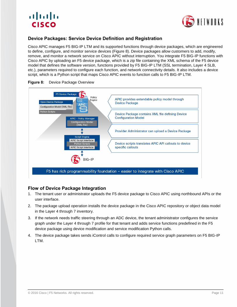
Device Packages: Service Device Definition and Registration
Cisco APIC manages F5 BIG-IP LTM and its supported functions through device packages, which are engineered
to define, configure, and monitor service devices (Figure 8). Device packages allow customers to add, modify,
remove, and monitor a network service on Cisco APIC without interruption. You integrate F5 BIG-IP functions with
Cisco APIC by uploading an F5 device package, which is a zip file containing the XML schema of the F5 device
model that defines the software version, functions provided by F5 BIG-IP LTM (SSL termination, Layer 4 SLB,
etc.), parameters required to configure each function, and network connectivity details. It also includes a device
script, which is a Python script that maps Cisco APIC events to function calls to F5 BIG-IP LTM.
Figure 8: Device Package Overview
Flow of Device Package Integration 1. The tenant user or administrator uploads the F5 device package to Cisco APIC using northbound APIs or the
user interface.
2. The package upload operation installs the device package in the Cisco APIC repository or object data model
in the Layer 4 through 7 inventory.
3. If the network needs traffic steering through an ADC device, the tenant administrator configures the service
graph under the Layer 4 through 7 profile for that tenant and adds service functions predefined in the F5
device package using device modification and service modification Python calls.
4. The device package takes sends iControl calls to configure required service graph parameters on F5 BIG-IP
LTM.

© 2016 Cisco | F5 Networks. All rights reserved. Page 12
Figure 9: Flow of Device Package Integration
The existing device package supports F5 BIG-IP LTM functions for Layer 4 through 7 network services. Any
additional modules - for example, F5 BIG-IP Access Policy Manager (APM), Advanced Firewall Manager (AFM),
Application Security Manager (ASM) - are supported through continued device package development after FCS.
Multitenancy
Cisco APIC administrators can allocate an F5 BIG-IP LTM device to a tenant. “Single tenant” means that the
device cluster cannot be shared across multiple tenants of a given type that are hosted on the provider network,
and the Cisco APIC administrator must give the device cluster to a specific tenant for a given tenant. “Multiple
tenant” indicates that the device or device cluster can be shared and used by multiple tenants hosted on the
provider network.
Tenants in F5 BIG-IP LTM devices are represented as partitions or route domains. Each route domain is used to
isolate traffic between different tenants with administrative credentials. A common partition is used to define
parameters shared among different tenants: for example, iRules. The F5 device package creates separate
partitions for tenants instantiated on Cisco APIC (Figure 10).
Figure 10: Tenants
F5 BIG-IP LTM helps ensure a multitenant model by creating a separate partition for each Cisco APIC tenant and
its association with a service graph through the contract. Upon deletion of a tenant from Cisco APIC, the device
package also deletes the partition from F5 BIG-IP. Figure 11 shows a logical model of multitenancy in the joint
solution.

© 2016 Cisco | F5 Networks. All rights reserved. Page 13
Figure 11: Multitenancy: Logical Model
F5 BIG IP LTM Deployment Options
F5 BIG-IP LTM can be deployed only in Go-to mode in Cisco APIC, where F5 BIG-IP serves as a default gateway
to all traffic in both one-arm and two-arm modes. In two-arm mode, either two interfaces are used for the input
and output flow of traffic, or single interface can be used with separate VLANs indicating the input and output flow
(Figure 12).
Note: Customers using F5 deployment models in today’s network can continue to use them in the Cisco ACI model.
© 2016 Cisco | F5 Networks. All rights reserved. Page 14
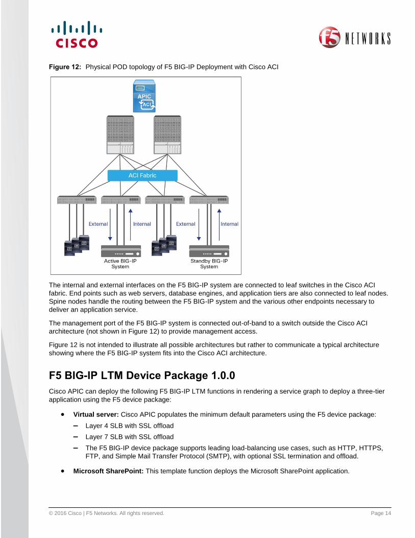
Figure 12: Physical POD topology of F5 BIG-IP Deployment with Cisco ACI
The internal and external interfaces on the F5 BIG-IP system are connected to leaf switches in the Cisco ACI
fabric. End points such as web servers, database engines, and application tiers are also connected to leaf nodes.
Spine nodes handle the routing between the F5 BIG-IP system and the various other endpoints necessary to
deliver an application service.
The management port of the F5 BIG-IP system is connected out-of-band to a switch outside the Cisco ACI
architecture (not shown in Figure 12) to provide management access.
Figure 12 is not intended to illustrate all possible architectures but rather to communicate a typical architecture
showing where the F5 BIG-IP system fits into the Cisco ACI architecture.
F5 BIG-IP LTM Device Package 1.0.0
Cisco APIC can deploy the following F5 BIG-IP LTM functions in rendering a service graph to deploy a three-tier
application using the F5 device package:
Virtual server: Cisco APIC populates the minimum default parameters using the F5 device package:
– Layer 4 SLB with SSL offload
– Layer 7 SLB with SSL offload
– The F5 BIG-IP device package supports leading load-balancing use cases, such as HTTP, HTTPS,
FTP, and Simple Mail Transfer Protocol (SMTP), with optional SSL termination and offload.
Microsoft SharePoint: This template function deploys the Microsoft SharePoint application.

© 2016 Cisco | F5 Networks. All rights reserved. Page 15
Multitenancy: The device package supports multitenancy on F5 BIG-IP LTM and maintains complete
isolation of traffic between tenants.
High availability for application services: F5 BIG-IP LTM provides fault tolerance at the application
layer (server downtime) as well as at the F5 BIG-IP layer (failure). The device package supports high
availability for F5 BIG-IP LTM devices connected to Cisco APIC.
Multiple graphs: Multiple virtual servers in the F5 BIG-IP partition and routing domain can share the
same physical F5 BIG-IP device.
F5 BIG-IP VE: Virtual F5 BIG-IP LTM is supported through the device package. Cisco APIC creates the
port group using VMM domain integration and automates vNIC assignment to F5 BIG-IP VE.
iRules: iRules that are configured and managed through F5 BIG-IP under the common partition can be
referenced from Cisco APIC using the name iRules parameter field. Cisco APIC cannot modify or create
new iRules in the F5 BIG-IP common partition (Figure 13).
Figure 13: Referencing iRules
Conclusion
As businesses quickly move to make the data center more agile, application-centric automation and virtualization
of both hardware and software infrastructure become increasingly important. Cisco ACI builds the critical link
between business-based requirements for applications and the infrastructure that supports them. The joint F5 and
Cisco ACI solution extends the F5 Syntheses architecture and programmable F5 SDAS into Cisco ACI through a
downloadable, easy-to-install device package, helping customers efficiently deploy applications that are fast,
secure, and available. Customers can transparently integrate existing F5 Synthesis and F5 BIG-IP topologies with
Cisco ACI, protecting existing application and architectural investments while enabling the operationalization of
the network, which is critical to success in today’s application environment.

© 2016 Cisco | F5 Networks. All rights reserved. Page 16
© 2016 Cisco and/or its affiliates. All rights reserved. Cisco and the Cisco logo are trademarks or registered
trademarks of Cisco and/or its affiliates in the U.S. and other countries. To view a list of Cisco trademarks, go to
this URL: www.cisco.com/go/trademarks. Third-party trademarks mentioned are the property of their respective
owners. The use of the word partner does not imply a partnership relationship between Cisco and any other
company. (1110R)
F5 (NASDAQ: FFIV) provides solutions for an application world. F5 helps organizations seamlessly scale cloud,
data center, and software defined networking (SDN) deployments to successfully deliver applications to
anyone, anywhere, at any time. F5 solutions broaden the reach of IT through an open, extensible framework
and a rich partner ecosystem of leading technology and data center orchestration vendors. This approach lets
customers pursue the infrastructure model that best fits their needs over time. The world's largest businesses,
service providers, government entities, and consumer brands rely on F5 to stay ahead of cloud, security, and
mobility trends. For more information, go to f5.com.
C11-732413-01 03/16
For More Information
Cisco Application Policy Infrastructure Controller: http://www.cisco.com/c/en/us/solutions/collateral/data-
center-virtualization/unified-fabric/white-paper-c11-730021.html
Cisco Application Centric Infrastructure services vision:
http://www.cisco.com/c/en/us/products/collateral/cloud-systems-management/aci-fabric-controller/white-
paper-c11-729998.html
F5 BIG-IP Local Traffic Manager 11.4.1 implementation: http://support.f5.com/kb/en-us/products/big-
ip_ltm/manuals/product/ltm-implementations-11-4-0.html
F5 BIG-IP and Cisco ACI integration demonstration http://www.youtube.com/watch?v=5Nw2vtid7Zs