autolog gsm-20 hardware manual - ff-automation gsm-20 hardware manual ff-automation oy 1 ......
TRANSCRIPT

AutoLog GSM-20 Hardware Manual
FF-Automation Oy
1
FF-AUTOMATION OY
HEAD OFFICE SERVICE CENTEREräkuja 2 Meijerikuja01600 VANTAA 37650 ValkeakoskiTel. +358-9-5306310 Tel. +358-3-5846390Fax. +358-9-53063130 Fax. +358-3-5846711http://www.ff-automation.come-mail:[email protected]
AutoLog GSM-20 Hardware Manual
Updated 27.09.2004

FF-Automation Oy
AutoLog GSM-20 Hardware Manual 2
1. SYSTEM COMPONENTS .........................................................................................................4
2. SPECIFICATIONS ...................................................................................................................102.1 Main Board GSM-20 ....................................................................................................102.2 Expansion board RO16 ................................................................................................112.3 Expansion board RIO8 .................................................................................................112.4 Expansion board DI16 ..................................................................................................112.5 Expansion board DO32 ................................................................................................122.6 Expansion board EXA8/4..............................................................................................122.7 GSM-20 Operating environment and storage...............................................................122.8 Display/keypad units .....................................................................................................13
3. COMPONENT LAYOUTS........................................................................................................143.1 Main Board GSM-20 .....................................................................................................143.2 Expansion board RO16 ................................................................................................143.3 Expansion board RIO8 .................................................................................................153.4 Expansion board DI16 ..................................................................................................153.5 Expansion board DO32 ................................................................................................163.6 Expansion board EXA8/4..............................................................................................16
4. SWITCHES..............................................................................................................................184.1 CPU GSM-20 and jumpers ...........................................................................................184.2 Expansion board RO16 ................................................................................................194.3 Expansion board RIO8 .................................................................................................194.4 Expansion board DI16 ..................................................................................................194.5 Address jumpers on DO32 board .................................................................................204.6 Adress jumpers on EXA8/4 board ................................................................................21
5. INDICATOR LIGHTS ...............................................................................................................225.1 GSM-20 ........................................................................................................................225.2 Indicator LEDs for inputs and outputs...........................................................................235.3 Indicator LEDs for outputs of RO16 board ...................................................................245.4 Indicator LEDs for inputs of DI16 board........................................................................255.5 Indicator LEDs for inputs RIO8.....................................................................................255.6 Indicator LEDs for outputs of DO32 board ...................................................................265.7 RUN led indicating function of EXA8/4 board ...............................................................275.8 Display/keypad unit AL1093DC ....................................................................................285.9 Display/keypad unit AL1093F .......................................................................................285.10 Display/keypad unit AL1094/R/AF ................................................................................285.11 Display/keypad unit AL1094FM ....................................................................................29
6.INSTALLATION AND CONNECTIONS ....................................................................................306.1 Environmental requirements.........................................................................................306.2 Field wiring....................................................................................................................306.3 Connection example digital inputs / outputs .................................................................326.4 Analog inputs ................................................................................................................366.5 Analog outputs ..............................................................................................................386.6 Serial communication ...................................................................................................396.7 Terminal strip numbering and connection diagrams.....................................................426.8 IButton cable connection ..............................................................................................476.9 GSM modem connections - SRT Appello...................................................................48
7. LIST OF GSM-PLC PRODUCTS.............................................................................................497.1 GSM-PLC .....................................................................................................................497.2 Accessory boards .........................................................................................................497.3 Analog /digital input modules........................................................................................49
TABLE OF CONTENT

AutoLog GSM-20 Hardware Manual
FF-Automation Oy
3
7.4 Programming and additional software ..........................................................................497.5 Power supplies..............................................................................................................507.6 GSM Modems ...............................................................................................................507.7 Programming and auxiliary cables................................................................................50
APPENDIX A DIMENSIONAL DRAWINGS.................................................................................51Figure A.1 Dimensions of GSM-20 ......................................................................................51Figure A.2 Dimensions of expansion board RO16...............................................................52Figure A.3 Dimensions of expansion board RIO8................................................................52Figure A.4 Dimensions of expansion board DI16.................................................................53Figure A.5 Dimensions of expansion board DO32...............................................................53Figure A.6 Dimensions of EXA8/4 analog expansion board ................................................54Figure A.7 Dimensions of display/keypad unit AL1094 .......................................................55Figure A.8 Dimensions of display/keypad unit AL1094R .....................................................55Figure A.9 Dimensions of display/keypad unit AL1094AF ..................................................56Figure A.10 Dimensions of display/keypad unit AL1094FM...................................................56Figure A.11 Dimensions of display/keypad unit AL1093D .....................................................57Figure A.12 Dimensions of display/keypad unit AL1093F......................................................57
FF-Automation Oy
AutoLog GSM-20 Hardware Manual 4
1. SYSTEM COMPONENTS
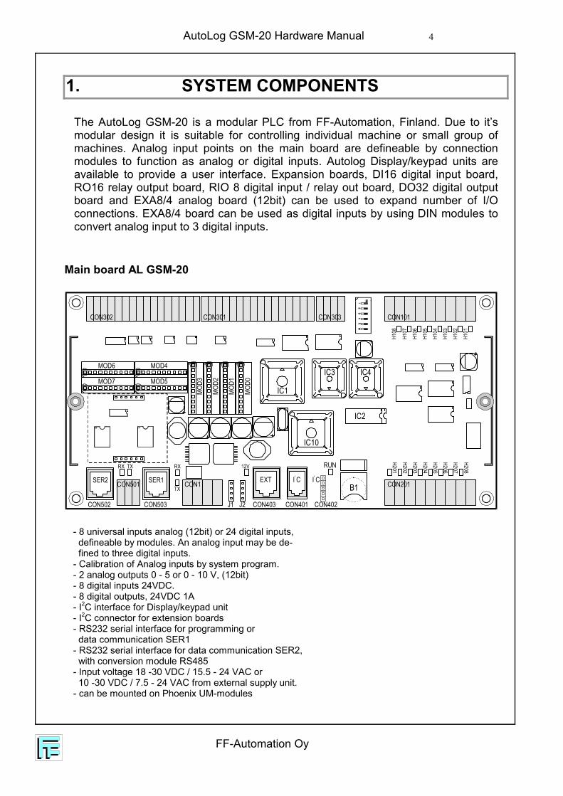
The AutoLog GSM-20 is a modular PLC from FF-Automation, Finland. Due to it’smodular design it is suitable for controlling individual machine or small group ofmachines. Analog input points on the main board are defineable by connectionmodules to function as analog or digital inputs. Autolog Display/keypad units areavailable to provide a user interface. Expansion boards, DI16 digital input board,RO16 relay output board, RIO 8 digital input / relay out board, DO32 digital outputboard and EXA8/4 analog board (12bit) can be used to expand number of I/Oconnections. EXA8/4 board can be used as digital inputs by using DIN modules toconvert analog input to 3 digital inputs.
Main board AL GSM-20
- 8 universal inputs analog (12bit) or 24 digital inputs, defineable by modules. An analog input may be de- fined to three digital inputs.- Calibration of Analog inputs by system program.- 2 analog outputs 0 - 5 or 0 - 10 V, (12bit)- 8 digital inputs 24VDC.- 8 digital outputs, 24VDC 1A- I2C interface for Display/keypad unit- I2C connector for extension boards- RS232 serial interface for programming or data communication SER1- RS232 serial interface for data communication SER2, with conversion module RS485- Input voltage 18 -30 VDC / 15.5 - 24 VAC or 10 -30 VDC / 7.5 - 24 VAC from external supply unit.- can be mounted on Phoenix UM-modules
IC1
IC3 IC4
IC2
B1
IC10
TX
MOD6 MOD4
MOD7 MOD5
MOD3
MOD2
MOD1
MOD0
TX
RX RX 12V
CON303 CON101
CON201CON1
CON403CON503 J1 J2CON502
CON501 SER1SER2
CON401 CON402
CON301CON302
RUN
EXT I C2
I C2
H101
H102
H103
H104
H105
H106
H107
H108
H201
H202
H203
H204
H205
H206
H207
H208

AutoLog GSM-20 Hardware Manual
FF-Automation Oy
5
Expansion board RO16
- 16 relay outputs, RC protection, outputs isolated from each other (two terminals)- I2C expansion interface- operation voltage supplied from main board- can be mounted on Phoenix UM-modules
Expansion board RIO8
- 8 relay outputs, RC protection, outputs isolated from each other (two terminals)- 8 in group isolated inputs for contacts 24VDC or PNP sensors- I2C expansion interface- operation voltage supplied from main board- can be mounted on Phoenix UM-modules
K8 K7 K6 K5 K4 K3 K2 K1 K16 K15 K14 K13 K12 K11 K10 K9
C11 C10 C9 C8 C7 C6 C5 C4 C3 C18 C17 C16 C15 C14 C13 C12
FROM CPU
CON1
CON101
H8 H7 H6 H5
J11-2 3-4 ADDR1 1 321 0 480 1 640 0 80
H12
H11
H10
H9H16
H15
H14
H13
H4 H3 H2 H1
CON103 CON102
CON2
TO EXT
IC8IC5 IC6
IC7
CON104
FROM
CPU
TO E
XT
CON1 CON2
www.FF-Automation.com
J1 1 2 3 4 5 61-2 3-4 5-6 ADDR 1-2 3-4 5-6 ADDR1 1 1 321 1 0 401 0 1 481 0 0 56
0 1 1 640 1 0 720 0 1 800 0 0 88
FF-Automation Oy
AutoLog GSM-20 Hardware Manual 6
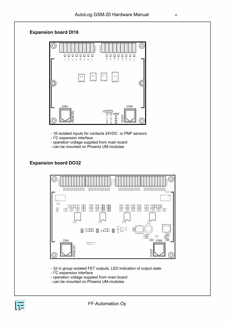
Expansion board DI16
- 16 isolated inputs for contacts 24VDC or PNP sensors- I2C expansion interface- operation voltage supplied from main board- can be mounted on Phoenix UM-modules
Expansion board DO32
- 32 in group isolated FET outputs, LED indication of output state- I2C expansion interface- operation voltage supplied from main board- can be mounted on Phoenix UM-modules
1
1
HC1C2
FROM
CPU
TO E
XT
CON1 CON2
J11-2 3-4 ADDR1 1 321 0 480 1 640 0 80
FROM
CPU
TO E
XT
CON1 CON2
AutoLog GSM-20 Hardware Manual
FF-Automation Oy
7
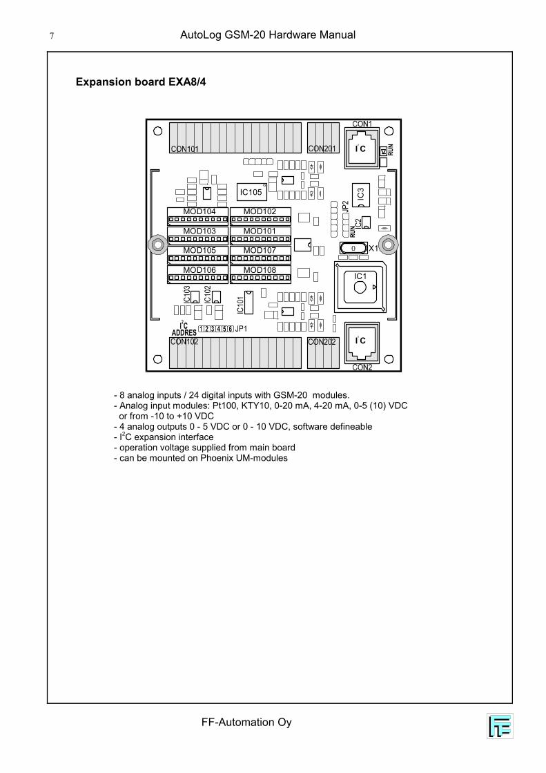
Expansion board EXA8/4
- 8 analog inputs / 24 digital inputs with GSM-20 modules.- Analog input modules: Pt100, KTY10, 0-20 mA, 4-20 mA, 0-5 (10) VDC or from -10 to +10 VDC- 4 analog outputs 0 - 5 VDC or 0 - 10 VDC, software defineable- I2C expansion interface- operation voltage supplied from main board- can be mounted on Phoenix UM-modules
MOD101MOD103
MOD102MOD104
MOD107MOD105
MOD108MOD106
IC3
IC2
JP2
IC10
1IC10
3
IC10
2
X1
IC1
IC105
RUN
RUN
I C2
I C2

FF-Automation Oy
AutoLog GSM-20 Hardware Manual 8
Display/keypad unit AL1094
- 4 digit LCD display- 8 keys (0 ... 7)- 4 LED indicator lights- I2C connection cable (0.25m) to PLC- operation voltage supplied from main board
0
4
1
5
2
6
3
7
Display/keypad unit AL1094R
- 2x16 digit alphanumeric LCD display, backlit- 4 keys (0 ... 3)- 2 LED indicator lights- I2C connection cable (0.25m) to PLC- operation voltage supplied from main board
0 1
2 3
Display/keypad units AL1094
- 2x20 digit alphanumeric LCD display, backlit- 8 keys (0 ... 7) / 16 keys (0 ... F)- 4 LED indicator lights- Clock and calendar with battery backup- buzzer- I2C connection cable (0.9m) to PLC- operation voltage supplied from main board- one 24VDC 300mA output for external indication light- resistance against interference and radiation; CE approved- operating temperature 0 - 55 °C- ambient humidity 5 - 95% RH, (non condensing)- cooling; natural air conditioning- open structure, not encapsulated- the unit can be fitted with a client designed face plate
1 2 3
5 6 71
2
3
4
0
4
1 2 3
5 6 7
0
4
8 9 A B
C D E F1
2
3
4
AL1094AF
AL1094FM
AutoLog GSM-20 Hardware Manual
FF-Automation Oy
9
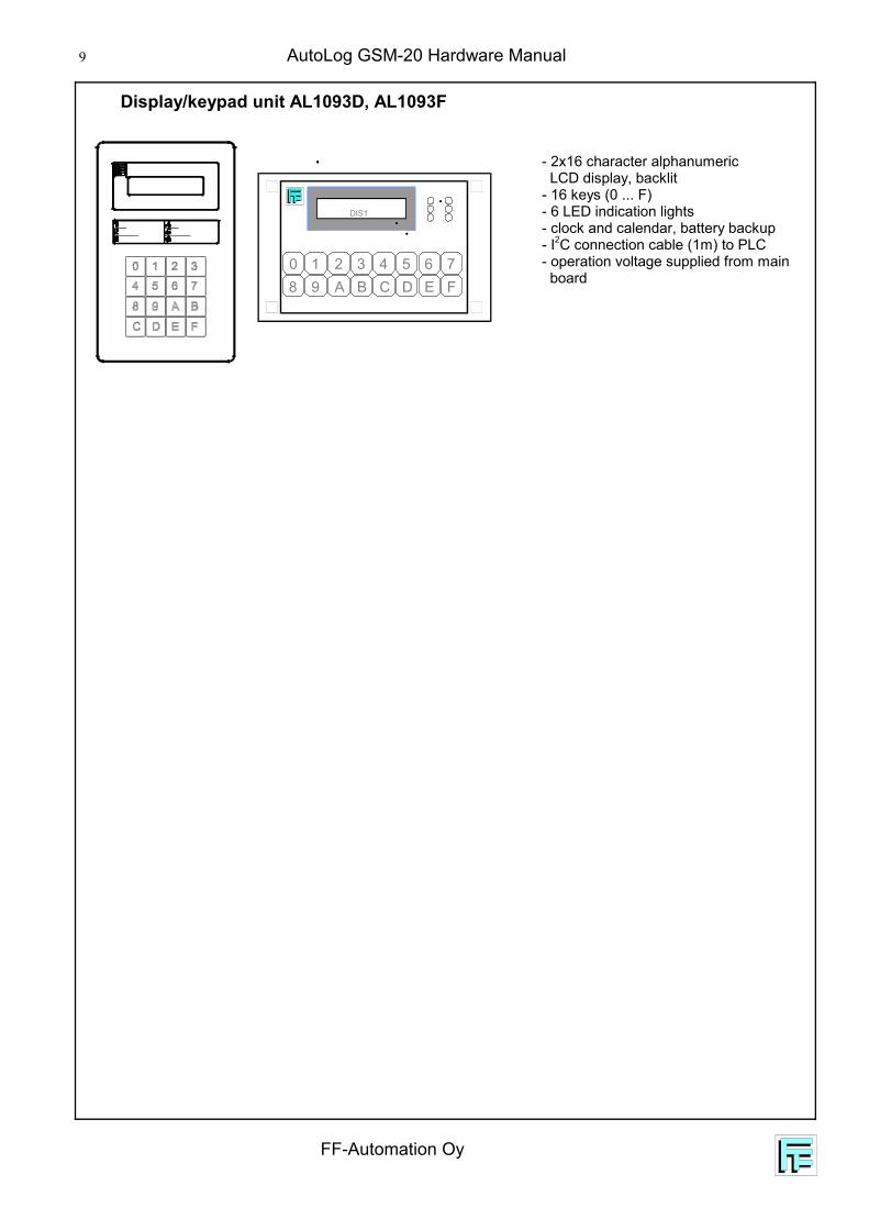
Display/keypad unit AL1093D, AL1093F
- 2x16 character alphanumeric LCD display, backlit- 16 keys (0 ... F)- 6 LED indication lights- clock and calendar, battery backup- I2C connection cable (1m) to PLC- operation voltage supplied from main board
DIS1
5 6 710 2 3 4D E F8 9 A B C
FF-Automation Oy
AutoLog GSM-20 Hardware Manual 10
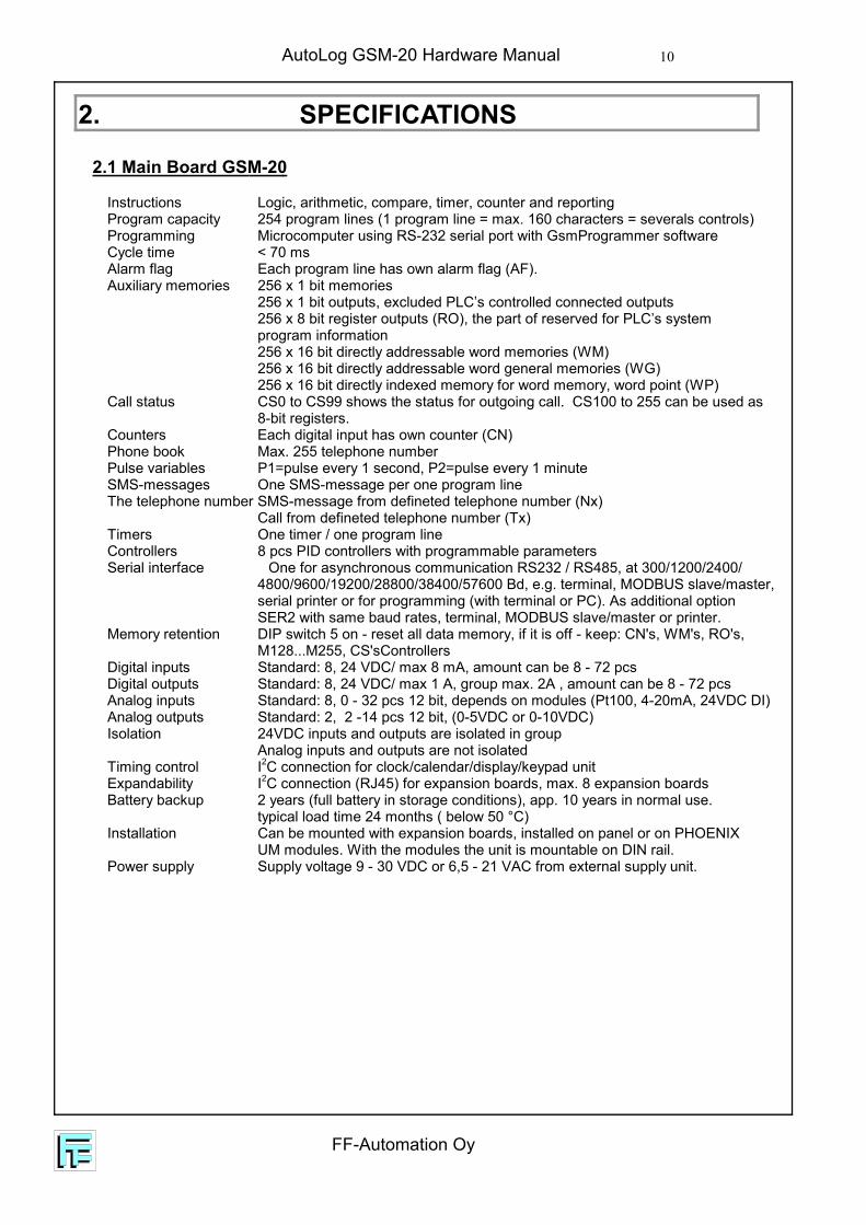
2.1 Main Board GSM-20
Instructions Logic, arithmetic, compare, timer, counter and reportingProgram capacity 254 program lines (1 program line = max. 160 characters = severals controls)Programming Microcomputer using RS-232 serial port with GsmProgrammer softwareCycle time < 70 msAlarm flag Each program line has own alarm flag (AF).Auxiliary memories 256 x 1 bit memories 256 x 1 bit outputs, excluded PLC’s controlled connected outputs
256 x 8 bit register outputs (RO), the part of reserved for PLC’s system program information
256 x 16 bit directly addressable word memories (WM)256 x 16 bit directly addressable word general memories (WG)256 x 16 bit directly indexed memory for word memory, word point (WP)
Call status CS0 to CS99 shows the status for outgoing call. CS100 to 255 can be used as 8-bit registers.
Counters Each digital input has own counter (CN)Phone book Max. 255 telephone numberPulse variables P1=pulse every 1 second, P2=pulse every 1 minuteSMS-messages One SMS-message per one program lineThe telephone number SMS-message from defineted telephone number (Nx)
Call from defineted telephone number (Tx)Timers One timer / one program lineControllers 8 pcs PID controllers with programmable parametersSerial interface One for asynchronous communication RS232 / RS485, at 300/1200/2400/
4800/9600/19200/28800/38400/57600 Bd, e.g. terminal, MODBUS slave/master,serial printer or for programming (with terminal or PC). As additional optionSER2 with same baud rates, terminal, MODBUS slave/master or printer.
Memory retention DIP switch 5 on - reset all data memory, if it is off - keep: CN's, WM's, RO's, M128...M255, CS'sControllers
Digital inputs Standard: 8, 24 VDC/ max 8 mA, amount can be 8 - 72 pcsDigital outputs Standard: 8, 24 VDC/ max 1 A, group max. 2A , amount can be 8 - 72 pcsAnalog inputs Standard: 8, 0 - 32 pcs 12 bit, depends on modules (Pt100, 4-20mA, 24VDC DI)Analog outputs Standard: 2, 2 -14 pcs 12 bit, (0-5VDC or 0-10VDC)Isolation 24VDC inputs and outputs are isolated in group
Analog inputs and outputs are not isolatedTiming control I2C connection for clock/calendar/display/keypad unitExpandability I2C connection (RJ45) for expansion boards, max. 8 expansion boardsBattery backup 2 years (full battery in storage conditions), app. 10 years in normal use.
typical load time 24 months ( below 50 °C)Installation Can be mounted with expansion boards, installed on panel or on PHOENIX
UM modules. With the modules the unit is mountable on DIN rail.Power supply Supply voltage 9 - 30 VDC or 6,5 - 21 VAC from external supply unit.
2. SPECIFICATIONS
AutoLog GSM-20 Hardware Manual
FF-Automation Oy
11
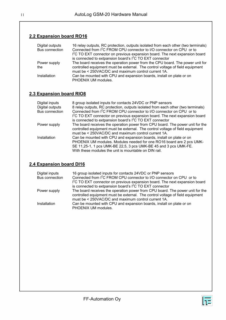
2.2 Expansion board RO16
Digital outputs 16 relay outputs, RC protection, outputs isolated from each other (two terminals)Bus connection Connected from I2C FROM CPU connector to I/O connector on CPU or to
I2C TO EXT connector on previous expansion board. The next expansion boardis connected to extpansion board’s I2C TO EXT connector
Power supply The board receives the operation power from the CPU board. The power unit forthe controlled equipment must be external. The control voltage of field equipment
must be < 250VAC/DC and maximum control current 1A.Installation Can be mounted with CPU and expansion boards, install on plate or on
PHOENIX UM modules.
2.3 Expansion board RIO8
Digital inputs 8 group isolated inputs for contacts 24VDC or PNP sensorsDigital outputs 8 relay outputs, RC protection, outputs isolated from each other (two terminals)Bus connection Connected from I2C FROM CPU connector to I/O connector on CPU or to
I2C TO EXT connector on previous expansion board. The next expansion boardis connected to extpansion board’s I2C TO EXT connector
Power supply The board receives the operation power from CPU board. The power unit for the controlled equipment must be external. The control voltage of field equipmentmust be < 250VAC/DC and maximum control current 1A.
Installation Can be mounted with CPU and expansion boards, install on plate or onPHOENIX UM modules. Modules needed for one RO16 board are 2 pcs UMK-SE 11,25-1, 1 pcs UMK-BE 22,5, 3 pcs UMK-BE 45 and 3 pcs UMK-FE.With these modules the unit is mountable on DIN rail.
2.4 Expansion board DI16
Digital inputs 16 group isolated inputs for contacts 24VDC or PNP sensorsBus connection Connected from I2C FROM CPU connector to I/O connector on CPU or to
I2C TO EXT connector on previous expansion board. The next expansion boardis connected to extpansion board’s I2C TO EXT connector
Power supply The board receives the operation power from CPU board. The power unit for the controlled equipment must be external. The control voltage of field equipmentmust be < 250VAC/DC and maximum control current 1A.
Installation Can be mounted with CPU and expansion boards, install on plate or onPHOENIX UM modules.

FF-Automation Oy
AutoLog GSM-20 Hardware Manual 12
2.5 Expansion board DO32
Digital outputs 32 in group isolated FET tarnsistor outputs.Bus connection Connected from I2C FROM CPU connector to I/O connector on CPU or to
I2C TO EXT connector on previous expansion board. The next expansion boardis connected to extpansion board’s I2C TO EXT connector
Power supply The board receives the operation power from the CPU board. The power unitfor the controlled equipment must be external.The control voltage of field equipment must be < 30VDC and maximum controlcurrent 1A, max. group current 2A .
Installation Can be mounted with CPU and expansion boards, install on plate or onPHOENIX UM modules.
2.6 Expansion board EXA8/4
Analog inputs 0 - 8 pcs 12 bit, depends on modules (Pt100, 0(4)-20mA, 0-150mV, 24vdc DI)Digital inputs 0 - 24 in steps of 3 inputs for potential free contacts, 24VDC (DIN module)Analog outputs 4 pcs 12 bit analog outputs, 0 - 5 VDC or 0 - 10 VDC, defineable by softwareBus connection Connected from I2C FROM CPU connector to I/O connector on CPU or to
I2C TO EXT connector on previous expansion board. The next expansion boardis connected to extpansion board’s I2C TO EXT connector
Power supply The board receives the operation power from CPU board. The power unit for the analog inputs external.
Installation Can be mounted with CPU and expansion boards, install on plate or onPHOENIX UM modules.
2.7 GSM-20 Operating environment and storage
Supply voltage 10 to 30 VDC / 7.5 to 21 VAC or18 to 30 VDC / 15 to 21 VAC from external power unit
Degree of protection IP20 (unprotected)Operating temperature -30 to +70 °C (with IP65 enclosure and power on)Storage temperature -40 to +80 °C (non-condensing)
AutoLog GSM-20 Hardware Manual
FF-Automation Oy
13
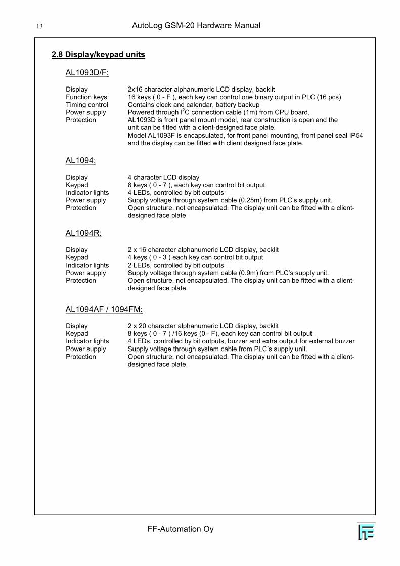
2.8 Display/keypad units
AL1093D/F:
Display 2x16 character alphanumeric LCD display, backlitFunction keys 16 keys ( 0 - F ), each key can control one binary output in PLC (16 pcs)Timing control Contains clock and calendar, battery backupPower supply Powered through I2C connection cable (1m) from CPU board.Protection AL1093D is front panel mount model, rear construction is open and the
unit can be fitted with a client-designed face plate.Model AL1093F is encapsulated, for front panel mounting, front panel seal IP54and the display can be fitted with client designed face plate.
AL1094:
Display 4 character LCD displayKeypad 8 keys ( 0 - 7 ), each key can control bit outputIndicator lights 4 LEDs, controlled by bit outputsPower supply Supply voltage through system cable (0.25m) from PLC’s supply unit.Protection Open structure, not encapsulated. The display unit can be fitted with a client-
designed face plate.
AL1094R:
Display 2 x 16 character alphanumeric LCD display, backlitKeypad 4 keys ( 0 - 3 ) each key can control bit outputIndicator lights 2 LEDs, controlled by bit outputsPower supply Supply voltage through system cable (0.9m) from PLC’s supply unit.Protection Open structure, not encapsulated. The display unit can be fitted with a client-
designed face plate.
AL1094AF / 1094FM:
Display 2 x 20 character alphanumeric LCD display, backlitKeypad 8 keys ( 0 - 7 ) /16 keys (0 - F), each key can control bit outputIndicator lights 4 LEDs, controlled by bit outputs, buzzer and extra output for external buzzerPower supply Supply voltage through system cable from PLC’s supply unit.Protection Open structure, not encapsulated. The display unit can be fitted with a client-
designed face plate.

FF-Automation Oy
AutoLog GSM-20 Hardware Manual 14
3. COMPONENT LAYOUT
3.1 Main Board GSM-20
CON1 Power supplyCON303 Analog outputsCON101 Digital inputsCON201 Digital outputsCON501 RS485 serial connectionCON502 RS232 serial connectionCON503 RS232 serial connectionCON401 I2C for display unit RJ45
3.2 Expansion board RO16
CON101 Relay outputs 0 - 3CON102 Relay outputs 4 - 7CON103 Relay outputs 8 - 11CON104 Relay outputs 12 - 15
174
134
154
114
173
133
153
113
172
132
152
112
171
131
151
111
164
124
144
104
84163
123
143
103
83162
122
142
102
82161
121
141
101
81 18 17 16 15 14 13 12 11 10
20 21 22 23 24 25 26 27 28
1 +24
V
2 GDN
3 AC2
4 AC1
D+ D- GND
IC1
IC3 IC4
IC2
B1
IC10
TX
MOD6 MOD4
MOD7 MOD5MO
D3
MOD2
MOD1
MOD0
TX
RX RX 12V
CON303 CON101
CON201CON1
CON403CON503 J1 J2CON502
CON501 SER1SER2
CON401 CON402
CON301CON302
RUN
EXT I C2
I C2
H101
H102
H103
H104
H105
H106
H107
H108
H201
H202
H203
H204
H205
H206
H207
H208
CON402 I2C for display unitCON403 I2C for expansion boards RJ45SW1 DIP-switchIC1 ProcessorIC10 Address coderIC2 Data-RAMIC3 System program FLASHIC4 Application program FLASH
15B
15A
14B
14A
13B
13A
12B
12A
11B
11A
10B
10A
9B 9A 8B 8A 3B 3A 2B 2A 1B 1A 0B 0A7B 7A 6B 6A 5B 5A 4B 4A
K8 K7 K6 K5 K4 K3 K2 K1 K16 K15 K14 K13 K12 K11 K10 K9
C11 C10 C9 C8 C7 C6 C5 C4 C3 C18 C17 C16 C15 C14 C13 C12
FROM CPU
CON1
CON101
H8 H7 H6 H5
J11-2 3-4 ADDR1 1 321 0 480 1 640 0 80
H12
H11
H10
H9H16
H15
H14
H13
H4 H3 H2 H1
CON103 CON102
CON2
TO EXT
IC8IC5 IC6
IC7
CON104
CON1 Control cable from CPUCON2 Control cable to expansion boards
Address codes for outputs in chapter 4.
AutoLog GSM-20 Hardware Manual
FF-Automation Oy
15
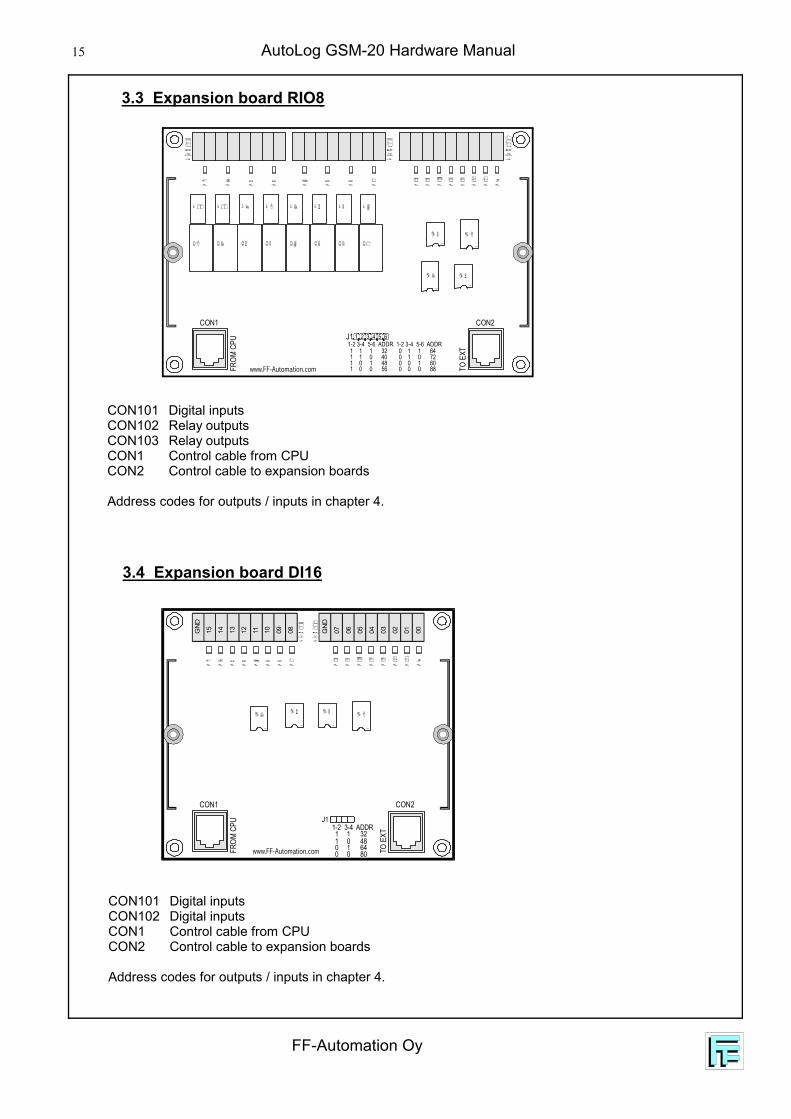
3.4 Expansion board DI16
CON101 Digital inputsCON102 Digital inputsCON1 Control cable from CPUCON2 Control cable to expansion boards
Address codes for outputs / inputs in chapter 4.
3.3 Expansion board RIO8
CON101 Digital inputsCON102 Relay outputsCON103 Relay outputsCON1 Control cable from CPUCON2 Control cable to expansion boards
Address codes for outputs / inputs in chapter 4.
J11-2 3-4 ADDR1 1 321 0 480 1 640 0 80www.FF-Automation.com
GN
D
15 14 13 12 11 10 09 08 GN
D
07 06 05 04 03 02 01 00
FROM
CPU
TO E
XT
CON1 CON2
FROM
CPU
TO E
XT
CON1 CON2
www.FF-Automation.com
J1 1 2 3 4 5 61-2 3-4 5-6 ADDR 1-2 3-4 5-6 ADDR1 1 1 321 1 0 401 0 1 481 0 0 56
0 1 1 640 1 0 720 0 1 800 0 0 88

FF-Automation Oy
AutoLog GSM-20 Hardware Manual 16
3.6 Expansion board EXA8/4
IC1 ProcessorCON1 Connection from CPU’s I2C display connectorCON2 Connection to display unit or to next EXA8/4 boardCON101 Analog inputsCON102 Analog inputsCON201 Analog outputsMOD101 - 108 Analog conversion module connectors
Address codes for outputs / inputs in chapter 4.
MOD101MOD103
MOD102MOD104
MOD107MOD105
MOD108MOD106
IC3
IC2
JP2
IC10
1IC10
3
IC10
2
X1
IC1
IC105
RUN
RUN
I C2
I C2
123
122
121
114
113
101
81131
112
102
82132
111
103
83133
104
84134
124
153
152
151
164
163
171
141
162
172
142
161
173
143
87 8885 86174
144
154
1
1
HC1C2
FROM
CPU
TO E
XT
CON1 CON2
www.FF-Automation.com
CO
M
CO
M20
820
720
620
520
420
320
220
1
CO
M21
621
521
421
321
221
121
020
9
224
CO
M
232
231
230
229
228
227
226
225
223
222
221
220
219
218
217
J1 1 2 3 4
J1 1-2 ADR 32J1 3-4 ADR 64
3.5 Expansion board DO32
CON101 Digital outputsCON102 Digital outputsCON201 Digital outputsCON202 Digital outputs
CON1 Control cable from CPUCON2 Control cable to expansion boards
Address codes for outputs / inputs in chapter 4.
AutoLog GSM-20 Hardware Manual
FF-Automation Oy
17
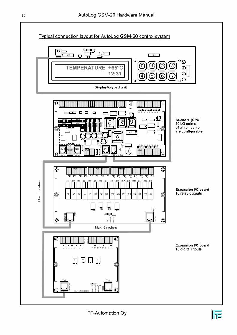
Typical connection layout for AutoLog GSM-20 control system M
ax. 5
met
ers
Max. 5 meters
K8 K7 K6 K5 K4 K3 K2 K1 K16 K15 K14 K13 K12 K11 K10 K9
C11 C10 C9 C8 C7 C6 C5 C4 C3 C18 C17 C16 C15 C14 C13 C12
FROM CPU
CON1
CON101H8 H7 H6 H5
J11-2 3-4 ADDR1 1 321 0 480 1 640 0 80
H12
H11
H10
H9H16
H15
H14
H13
H4 H3 H2 H1
CON103 CON102
CON2
TO EXT
IC8IC5 IC6
IC7
CON104
1 2 3
5 6 71
2
3
4
IC3
IC2
IC1
0
4
Display/keypad unit
Expansion I/O board16 relay outputs
Expansion I/O board16 digital inputs
AL20AN (CPU)20 I/O points,of which someare configurable
TEMPERATURE +65°C 12:31
IC1
IC3 IC4
IC2
B1
IC10
TX
MOD6 MOD4
MOD7 MOD5
MOD3
MOD2
MOD1
MOD0
TX
RX RX 12V
CON303 CON101
CON201CON1
CON403CON503 J1 J2CON502
CON501 SER1SER2
CON401 CON402
CON301CON302
RUN
EXT I C2
I C2
H101
H102
H103
H104
H105
H106
H107
H108
H201
H202
H203
H204
H205
H206
H207
H208
J11-2 3-4 ADDR1 1 321 0 480 1 640 0 80www.FF-Automation.com
FROM
CPU
TO E
XT
CON1 CON2
FF-Automation Oy
AutoLog GSM-20 Hardware Manual 18
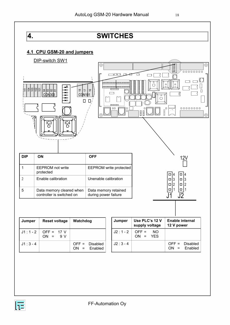
4. SWITCHES
4.1 CPU GSM-20 and jumpers
DIP-switch SW1
IC3 IC4
111
104
84103
83102
82101
81 18 17 16
CON303 CON101
DIP ON OFF
1 EEPROM not writeprotected
EEPROM write protected
2 Enable calibration Unenable calibration
5 Data memory cleared whencontroller is switched on
Data memory retainedduring power failure
12V
J1 J211223344
Jumper Reset voltage Watchdog
J1 : 1 - 2 OFF = 17 V ON = 9 V
J1 : 3 - 4 OFF = Disabled ON = Enabled
Jumper Use PLC’s 12 Vsupply voltage
Enable internal12 V power
J2 : 1 - 2 OFF = NO ON = YES
J2 : 3 - 4 OFF = Disabled ON = Enabled

AutoLog GSM-20 Hardware Manual
FF-Automation Oy
19
4.4 Expansion board DI16
4.3 Expansion board RIO8
J1: 1-2 J1: 3-4 J1: 5-6 Address
ON ON ON 32 - 39
OFF ON ON 40 - 47
ON OFF ON 48 - 55
OFF OFF ON 56 - 63
ON ON OFF 64 - 71
OFF ON OFF 72 - 79
ON OFF OFF 80 - 87
OFF OFF OFF 88 - 95
J1: 1-2 J1: 3-4 Address
ON ON 32 - 47
OFF ON 48 - 63
ON OFF 64 - 79
OFF OFF 80 - 95
4.2 Expansion board RO16
J1: 1-2 J1: 3-4 Address
ON ON 32 - 47
OFF ON 48 - 63
ON OFF 64 - 79
OFF OFF 80 - 95
K8 K7 K6 K5 K4 K3 K2 K1 K16 K15 K14 K13 K12 K11 K10 K9
C11 C10 C9 C8 C7 C6 C5 C4 C3 C18 C17 C16 C15 C14 C13 C12
FROM CPU
CON1
CON101
H8 H7 H6 H5J1
1-2 3-4 ADDR1 1 321 0 480 1 640 0 80
H12
H11
H10
H9H16
H15
H14
H13
H4 H3 H2 H1
CON103 CON102
CON2
TO EXT
IC8IC5 IC6
IC7
CON104
J11-2 3-4 ADDR1 1 321 0 480 1 640 0 80www.FF-Automation.com
FROM
CPU
TO E
XT
CON1 CON2
FROM
CPU
TO E
XT
CON1 CON2
www.FF-Automation.com
J1 1 2 3 4 5 61-2 3-4 5-6 ADDR 1-2 3-4 5-6 ADDR1 1 1 321 1 0 401 0 1 481 0 0 56
0 1 1 640 1 0 720 0 1 800 0 0 88

FF-Automation Oy
AutoLog GSM-20 Hardware Manual 20
Jumpers 1 - 2 3 - 4
Outputchannel
1 32 64
2 33 65
3 34 66
4 35 67
5 36 68
6 37 69
7 38 70
8 39 71
9 40 72
10 41 73
11 42 74
12 43 75
13 44 76
14 45 77
15 46 78
16 47 79
17 48 80
18 49 81
19 50 82
20 51 83
21 52 84
22 53 85
23 54 86
24 55 87
25 56 88
26 57 89
27 58 90
28 59 91
29 60 92
30 61 93
31 62 94
32 63 95
4.5 Address jumpers on DO32 board
1
1
HC
1C
2
FROM CPU
TO EXT
CO N1CO
N2
www.FF-Automation.com
J11
23
4
J1 1-2 ADR 32J1 3-4 ADR 64

AutoLog GSM-20 Hardware Manual
FF-Automation Oy
21
MOD101MOD103
MOD102MOD104
MOD107MOD105
MOD108MOD106
IC3
IC2
JP2
IC10
1IC10
3
IC10
2
X1
IC1
IC105
RUN
RUN
I C2
I C2
Jumpers 1 - 2 3 - 4 5 - 6 Analog Analog Digital
Card Address(RO4)
inputs outputs inputs
1 ON ON ON 32 - 39 32 - 35 96 - 119
2 ON ON OFF 40 - 47 40 - 43 120 - 143
3 ON OFF ON 48 - 55 48 - 51 144 - 167
4 ON OFF OFF 56 - 63 56 - 59 168 - 191
5 OFF ON ON 64 - 71 64 - 67 192 - 239
6 OFF ON OFF 72 - 79 72 - 75
7 OFF OFF ON 80 - 87 80 - 83
8 OFF OFF OFF 88 - 95 88 - 91
4.6 Address jumpers on EXA8/4 board

FF-Automation Oy
AutoLog GSM-20 Hardware Manual 22
5. INDICATOR LIGHTS
5.1 GSM-20
An amber LED indicator light indicates the functional state of the controller as follows:
B1
D+ D- GND
TX
TX
RX RX 12V
1 +24
V
2 GDN
3 AC2
4 AC1
CON1
CON403CON503 J1 J2CON502
CON501SER2 SER1
CON401 CON402
RUN
EXT I C2
I C2
LIGHT PROGRAM STATE CAUSED BY
Steady light Initialising PLC After power on
Slow blink(period 2 sec)
Initialising Modem
Very slow blink(period 4 sec)
Normal work
Fast blink(period 0,5 sec)
PLC does not executelogic program, but canreceive and response tomessages (SET, READ)
Very fast blink(period 0,1 sec)
Power fail state All outputs are cleared
Slow/fast blink Active alarm that needsacknowledging
AutoLog GSM-20 Hardware Manual
FF-Automation Oy
23
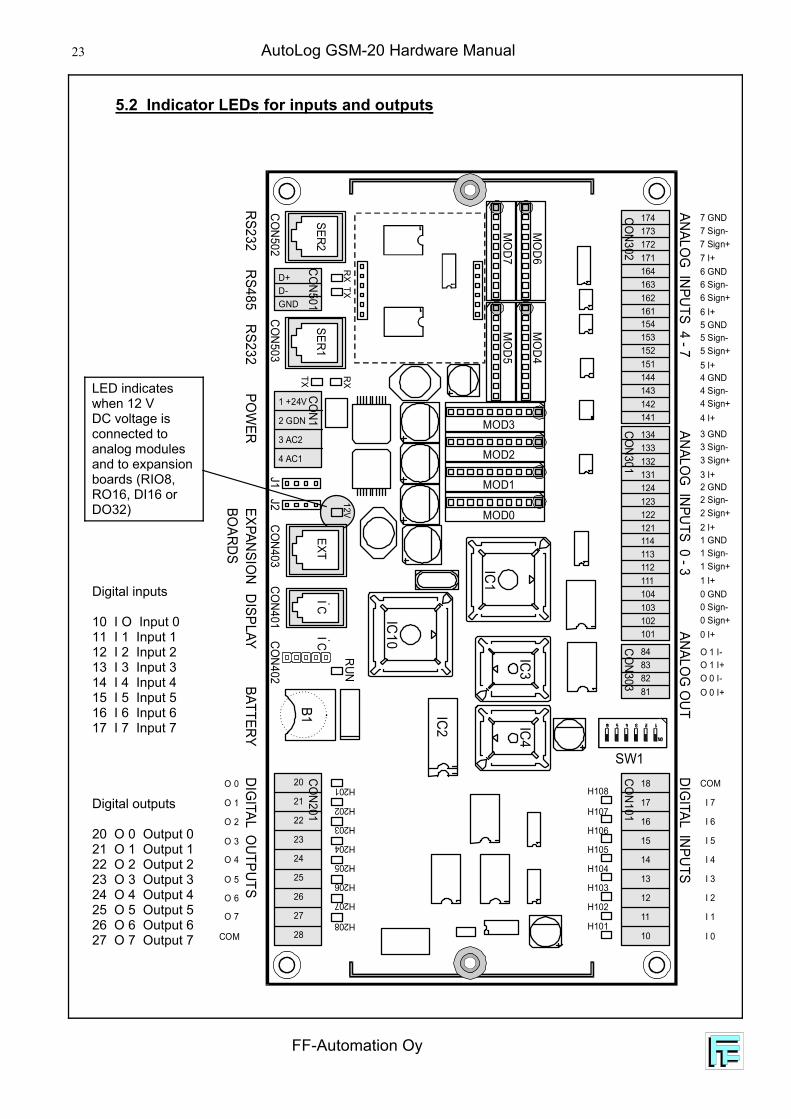
5.2 Indicator LEDs for inputs and outputs
Digital inputs
10 I O Input 011 I 1 Input 112 I 2 Input 213 I 3 Input 314 I 4 Input 415 I 5 Input 516 I 6 Input 617 I 7 Input 7
Digital outputs
20 O 0 Output 021 O 1 Output 122 O 2 Output 223 O 3 Output 324 O 4 Output 425 O 5 Output 526 O 6 Output 627 O 7 Output 7
174
134
154
114
173
133
153
113
172
132
152
112
171
131
151
111
164
124
144
104
84
163
123
143
103
83
162
122
142
102
82
161
121
141
101
81
18
17
16
15
14
13
12
11
10
20
21
22
23
24
25
26
27
28
1 +24V
2 GDN
3 AC2
4 AC1
D+D-GND
IC1
IC3IC4
IC2
B1
IC10
TX
MO
D6M
OD4
MO
D7M
OD5
MOD3
MOD2
MOD1
MOD0
TX
RXRX
12V
CON303CO
N101
CON201
CON1
CON403CON503
J1J2
CON502
CON501SER1
SER2
CON401
CON402
CON301CO
N302
RUN
EXTIC 2
IC 2
DIGITAL INPUTS
DIGITAL O
UTPUTSEXPANSIO
NBO
ARDSDISPLAY
BATTERYPO
WER
RS232RS485
RS232
ANALOG
INPUTS 4 - 7ANALO
G INPUTS 0 - 3
SW1
ANALOG
OUT
O 0
O 1
O 2
O 3
O 4
O 5
O 6
O 7
COM
COM
0 Sign-
4 Sign-
2 Sign-
6 Sign-
1 Sign-
5 Sign-
3 Sign-
7 Sign-
O 1 I+
0 Sign+
4 Sign+
2 Sign+
6 Sign+
1 Sign+
5 Sign+
3 Sign+
7 Sign+
O 0 I-
0 I+
4 I+
2 I+
6 I+
1 I+
5 I+
3 I+
7 I+
O 0 I+
0 GND
4 GND
2 GND
6 GND
1 GND
5 GND
3 GND
7 GND
O 1 I-
I 0
I 1
I 2
I 3
I 4
I 5
I 6
I 7
H101
H102
H103
H104
H105
H106
H107
H108H201
H202
H203
H204
H205
H206
H207
H208
LED indicateswhen 12 VDC voltage isconnected toanalog modulesand to expansionboards (RIO8,RO16, DI16 orDO32)

FF-Automation Oy
AutoLog GSM-20 Hardware Manual 24
5.3 Indicator LEDs for outputs of RO16 board
Output numbers shown in picture are smallestpossible address values on expansion board.
15B
15A
14B
14A
13B
13A
12B
12A
11B
11A
10B
10A
9B
9A
8B
8A
3B
3A
2B
2A
1B
1A
0B
0A
7B
7A
6B
6A
5B
5A
4B
4A
K8
K7
K6
K5
K4
K3
K2
K1
K16
K15
K14
K13
K12
K11
K10
K9
C11
C10
C9
C8
C7
C6
C5
C4
C3
C18
C17
C16
C15
C14
C13
C12
FROM CPU
CON1
CO
N101
H8
H7
H6
H5
J11-2 3-4 ADDR1 1 321 0 480 1 640 0 80
H12
H11
H10
H9
H16
H15
H14
H13
H4
H3
H2
H1
CO
N103
CO
N102
CON2TO EXT
IC8
IC5
IC6
IC7
CO
N104
O 40
O 41
O 42
O 43
O 44
O 45
O 46
O 47
O 32
O 33
O 34
O 35
O 36
O 37
O 38
O 39

AutoLog GSM-20 Hardware Manual
FF-Automation Oy
25
5.4 Indicator LEDs for inputs of DI16 board
Input numbers shownin picture are smallestpossible addressvalues on expansionboard.
J11-2 3-4 ADDR1 1 321 0 480 1 640 0 80www.FF-Automation.com
GN
D
15 14 13 12 11 10 09 08 GN
D
07 06 05 04 03 02 01 00
FROM
CPU
TO E
XTCON1 CON2
GN
D
I 47
I 46
I 45
I 44
I 43
I 42
I 41
I 40
GN
D
I 39
I 38
I 37
I 36
I 35
I 34
I 33
I 32
5.5 Indicator LEDs for inputs of RIO8 board
FROM
CPU
TO E
XT
CON1 CON2
www.FF-Automation.com
J1 1 2 3 4 5 61-2 3-4 5-6 ADDR 1-2 3-4 5-6 ADDR1 1 1 321 1 0 401 0 1 481 0 0 56
0 1 1 640 1 0 720 0 1 800 0 0 88
I 39
O 3
9
I 38
O 3
8
I 37
O 3
7
I 36
O 3
6
I 35
O 3
5
I 34
O 3
4
I 33
O 3
3
I 32
O 3
2
Input and output numbers shown in picture are smallest possibleaddress values on expansion board.
FF-Automation Oy
AutoLog GSM-20 Hardware Manual 26
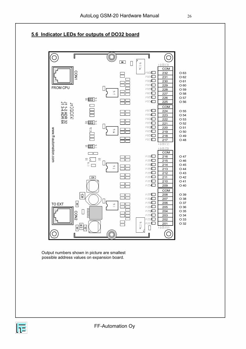
5.6 Indicator LEDs for outputs of DO32 board
FROM CPU
TO EXT
1
1
HC
1C
2
COM
COM208207206205204203202201
COM216215214213212211210209
224COM
232231230229228227226225
223222221220219218217
CON1
CON2
J11
23
4
J1 1-2 ADR 32
www.ff-automation.com
J1 3-4 ADR 64
O 39O 38O 37O 36O 35O 34O 33O 32
O 47O 46O 45O 44O 43O 42O 41O 40
O 55O 54O 53O 52O 51O 50O 49O 48
O 63O 62O 61O 60O 59O 58O 57O 56
Output numbers shown in picture are smallestpossible address values on expansion board.
AutoLog GSM-20 Hardware Manual
FF-Automation Oy
27
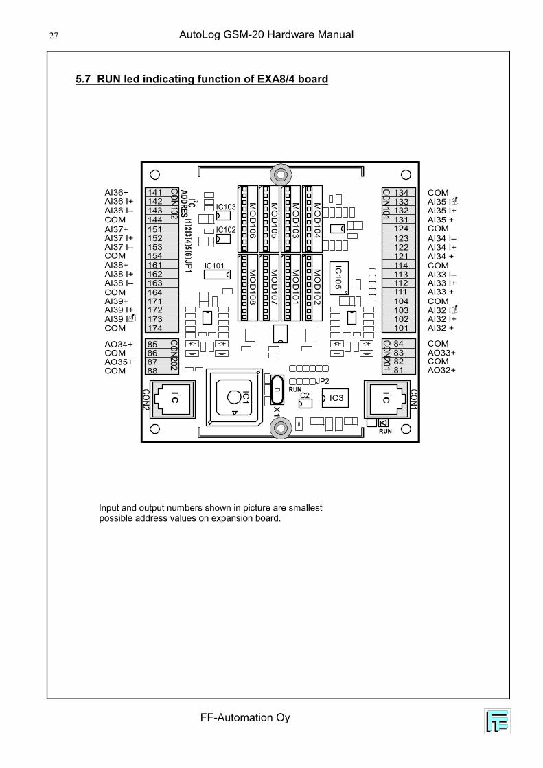
5.7 RUN led indicating function of EXA8/4 board
MO
D101
MO
D103
MO
D102
MO
D104
MO
D107
MO
D105
MO
D108
MO
D106
IC3IC2
JP2
IC101
IC103
IC102
X1
IC1
IC105
RUN
RUN IC 2
IC 2
123122121114113
101
81
131
112
102
82
132
111
103
83
133
104
84
134
124
153152151
164163
171
141
162
172
142
161
173
143
8788
8586
174
144
154
AI34 I–AI34 I+AI34 +COMAI33 I–
AI32 +
AO32+
AI35 +
AI33 I+
AI32 I+
COM
AI35 I+
AI33 +
AI32 I
AO33+
AI35 I
COM
COM
COM
COM
AI37 I–AI37 I+AI37+
COMAI38 I–
AI39+
AI36+
AI38 I+
AI39 I+
AI36 I+
AI38+
AI39 I
AI36 I–
AO35+COM
AO34+COM
COM
COM
COM
Input and output numbers shown in picture are smallestpossible address values on expansion board.

FF-Automation Oy
AutoLog GSM-20 Hardware Manual 28
5.8 Display/keypad unit AL1093DC
The board has six indicatorlights controlled by registeroutput R O 204
5.9 Display/keypad unit AL1093F
The board has six indicatorlights controlled by registeroutput R O 204
5.10 Display/keypad unit AL1094/R/AF
The boards has two / four indicator lightscontrolled by register output R O 204.
AL1094AF AL1094R
AL1094

AutoLog GSM-20 Hardware Manual
FF-Automation Oy
29
5.11 Display/keypad unit AL1094FM
The board has four indicator lights, buzzer andoutput controlled by register output R O 204
1 2 3
5 6 7
0
4
8 9 A B
C D E F1
2
3
4 LED4
LED4
LED4
LED4

FF-Automation Oy
AutoLog GSM-20 Hardware Manual 30
6. INSTALLATION AND CONNECTIONS
The inputs and outputs of the GSM-20 CPU board are isolated in group and theinputs of the expansion boards and inputs accomplished with DIN modules are notisolated. The serial connectors RS232 and parallel with it RS485 (SER1) andRS232 (SER2) are not isolated from PLC’s internal voltages. To ensure properfunction of GSM-20 the installation circumstances must be carefully considered.
Operating temperature - 35 to + 55°C (with IP65 enclosure and power on)
Moisture, corrosive gases, liquids and conductive dust must not be present where PLC boards are installed.
The PLC boards don't resist heavy vibration very well.
The distance from electromagnetic field generating devices, such as electricmotors, switch gear, thyristors, welding equipment, switched power supplies and power converters/inverters must be adequate.
PLC boards are quite immune against powerfull light sources.
If some item above or any other envinronmental feature may cause errors to PLCfunction it is advisable to install the PLC in the steel plate enclosure. It is alsoad-visable to install possible auxiliary input/output relays fuses and power units intheir own enclosure near the PLC. All the contactors connected to PLC have tobe equipped with RC protection devices and the 24 VDC control relays withextinguish diodes.
6.2 Field wiring
6.2.1 Earthing/grounding
The metal parts of the PLC enclosure must be connected to the plant’s logicground.
6.2.2 Power supply connections
Normally no functional grounding is necessary when 24 volt floating voltage systemis used with the PLC’s power supply connection. It is important that the 24 voltwiring is carefully kept isolated from ground level and 230 volt supply voltages.
The CPU board, GSM-20 receives the +24 V DC supply voltage from an external,isolated power supply unit (such as AL 9624/3.5 or AL 9624/8). The controllerconverts this to the voltages it requires.
6.1 Environmental requirements
AutoLog GSM-20 Hardware Manual
FF-Automation Oy
31
Expansion boards DI16, RIO8 and RO16 receive their supply power from CPUboard through the bus cable. Input board DI16 and the input part of the boardRIO8 doesn’t need any external power supplies. The control/operating power forthe controlled loads must be taken from external supply units.
6.2.3 Digital inputs
The digital inputs are isolated in group on GSM-20 CPU board. Externally poweredpotential free contacts or PNP type inductive/capacitive sensors may be connectedto PLC. The supply voltage for the PNP sensors is normally taken from external I/Opower unit.It is recommended to use twisted pair shielded cables in input wiring. The cablingshould be installed separately from the 230/400 VAC power cabling. The cableshields may be connected to logic ground only at one point, normally at the end onthe PLC enclosure. If there is heavy electromagnetic disturbance, the PLC’sunisolated inputs can be isolated from field equipment with relays or optoelectronicmodules.Look at chapter 6.3.3.
6.2.4 Digital outputs
The digital outputs are isolated in group on GSM-20 CPU board. Only low powered24VDC control relays, LED indicating lights or 24 volt indicating lights may beconnected to CPU outputs. The supply voltage for loads is taken from external I/Opower unit.It is recommended to use twisted pair shielded cables in output wiring. The cablingshould be installed separately from the 230/400 VAC power cabling. The cableshields may be connected to logic ground only at one point, normally at the end onthe PLC enclosure. If there is heavy electromagnetic disturbance, the PLC’sisolated outputs can be double isolated from field equipmnet with relays oroptoelectronic modules. Look at chapter 6.3.3.
6.2.5 Analog inputs/outputs
The analog inputs and outputs are unisolated in GSM-20 CPU board. If activetransducers are used, it should be checked that the output circuits of the transdu-cers are galvanically isolated from it’s supply voltages. If you can’t be sure of iso-lation, it is advisable to furnish the transducer with an external galvanic isolator.The supply power for passive transducer is normally taken from PLC’s power unit.The impedance of GSM-20’s analog milliamper input is 46Ω.It is recommended to use twisted pair shielded cables in output wiring. The ca-bling should be installed separately from the 230/400 VAC power cabling. The ca-ble shields may be connected to logic ground only at one point, normally at theend on the PLC enclosure. The analog modules are needed for analog inputs.The analog modules are extra equipments (Look chapter 7. LIST OF PROD-UCTS). RMS analog input modules requires 12 VDC power to function. Look atpage 6.5 section Power supply connection for expansion boards and DINmodules how to check that 12 VDC power is connected.

FF-Automation Oy
AutoLog GSM-20 Hardware Manual 32
6.3 Connection examples digital inputs / outputs
Threre are 8 - 32 digital inputs on GSM20 CPU board. 8 inputs of those areisolated in group from PLC’s internal voltages. Inputs connected vith DIN modulesto analog inputs are not isolated. The 8 inputs on RIO8 expansion board and 16digital inputs on DI16 expansion board are not isolated.Terminal strips for 2,5 mm2
wire are provided.
6.3.1 Connecting a switch or PNP sensor to isolated digital input on CPU board
6 - 30 VDC
Switch
PNPsensor
ExternalInternal
I1
GND
I0
GSM-20 , isolated DI16, RIO8 or AL20DIN module (3 Inputs)

AutoLog GSM-20 Hardware Manual
FF-Automation Oy
33
6.3.2 Connecting loads to digital outputs
There are 8 digital outputs, isolated in group, on GSM20 V01212 CPU board, 8 relayoutputs on RIO8 expansion board and 16 relay outputs on RO16 expansion board.Terminal strips for 2,5 mm2 wire are provided.
Connection of load to groupisolated transistor output
Connection of load to relay output
( )
( )
RIO8 or RO16 boardRIO8 or RO16 board
LoadN(/ )
+0 - 240 VAC(/DC)
Load
On
On
COMLoad
Load
+0 - 240 VAC(/DC)
+0 - 240 VAC(/DC)
N(/ )
N(/ )
( )
( )
On
On
O0 ... O7
O0 ... O7
GSM20 v01212CPU board
Load
Load
28
COM
20
21
12 - 30 VDC

FF-Automation Oy
AutoLog GSM-20 Hardware Manual 34
6.3.3 Optoelectronic / relay isolation of inputs and outputs
Since the inputs and outputs (excluding relay outputs) are not isolated on GSM20boards, it is advisable to provide external isolation in an environment prone todisturbances. A suitable solution is the use of PHOENIX digital optical inputinterface modules and relay output modules. The Modules protect the PLC againstthe static discharges and cut the circulating fault currents. The modules aremechanically fully protected DIN rail units.
Features of the I/O modules:
very long life optoelectronic isolation rated at 2500 V low power consumption vibration proof
PHOENIX’s digital I/O modules
type I/O voltage max. current logic voltage
DEK-OE-24DCDEK-OE-230ACDEK-REL-24/1/SEN
24 ± 20% VDC230 ± 10% VAC12 - 250 VAC10 - 125 VDC
3 A
24 V24 V24 V24 V
OE modules are inputmodules and REL modules are relay output modules.
PHOENIX modules: DEK-OE input module and DEK-REL type output module

AutoLog GSM-20 Hardware Manual
FF-Automation Oy
35
The figure below shows how Phoenix DEK-... -interface modules may beconnected to GSM20 V01212 CPU board’s group isolated input/output points.
FIELD CONTROL
PHOENIX
DEK-OE-...VAC/DC
DEK-OE-...VAC/DC
DEK...
A1 +
A2A
0
A1 +
A2A
0
+~ ( ) -N ( )
DEK-REL-...SEN
DEK-REL-...SEN13 A1
14A2
13 A1
14A2
+~ ( )-N ( )
I/O Powersupply
IC1
IC3IC4
IC2
B1
IC10
114113112111104
84
103
83
102
82
101
81
18
17
16
15
14
13
12
11
10
20
21
22
23
24
25
26
27
28
CON303CON101
CON201
CON401CON402
RUN
IC 2
IC 2

FF-Automation Oy
AutoLog GSM-20 Hardware Manual 36
6.4 Analog inputs
There are 0 - 8 individually adaptable analog inputs that can be used for themeasurement of temperature, current or voltage signals. The number of availableanalog inputs is defined according to adapter modules. Part or all of analog inputscan be defined as digital inputs by adapter modules. Analog inputs are not isolatedfrom PLC vlotages. Every measured signal / range needs its own individualadapter module.(Look chapter 7. LIST OF PRODUCTS).
6.4.1 Connection examples
Because of the low signal levels to be measured, shielded twisted-pair cablesshould be used. The shield should be grounded at one end only in order to avoiddegradation of accuracy by external disturbances.
Temperature measurement with a PT100 sensor
The current (I+ - I-) flows through the PT100 sensor.The measurement is made by inputs sign+ and sign-
Voltage measurement
Two ranges are available: 0...5V or 0...10V.
Current measurement
Two ranges are available: 0...20mA or 4...20mA.
+
-
GND
I+ 4...20 mAPower unitfor PLC
24 VDCI-
sign-
sign+
121
122
123
124
Passive transm.

AutoLog GSM-20 Hardware Manual
FF-Automation Oy
37
In order to make the adjustment of thePt100 input as accurate as possible overthe measurement range, different adjust-ment points have to be used. Instead ofadjusting the OFFSET at the lowest valuewe use a 10% point as the adjustment pointfor the low end of the measurement range.In the same way we use the 90% point asthe adjustment point for the high value. Thisincreases the overall accuray.The curve in picture is exaggerated.
6.4.2 Temperature measurement with a PT100 sensor
The Pt100 sensor is nonlinear. The following temperatures corresponds tothe resistance values given in the table (DIN 43 760) below:
°C
-50-45-40-35-30-25-20-15-10-505
101520253035404550
80.3182.2984.2786.2588.2290.1992.1694.1296.0698.04100101.95103.90105.85107.79109.73111.67113.61115.54117.47119.40
Diff.
0.400.400.390.390.390.390.390.390.390.390.390.390.390.390.390.380.390.390.390.390.39
°C
556065707580859095
100105110115120125130135140145150155
121.32123.24125.16127.07128.98130.89132.80134.79136.60138.50140.39142.29144.17146.06147.94149.82151.70153.58155.45157.31159.04
Diff.
0.390.380.390.380.380.380.380.380.380.380.370.390.370.380.370.370.370.380.380.370.37
°C
160165170175180185190195200205210215220225230235240245250255260
161.04162.90164.76166.61168.46170.31172.16174.00175.84177.68179.51181.34183.17184.99186.82188.63190.45192.26194.07195.88197.69
Diff.
0.370.370.370.370.370.370.370.370.370.370.370.370.370.360.370.360.360.360.360.360.36

FF-Automation Oy
AutoLog GSM-20 Hardware Manual 38
6.5 Analog outputs
The GSM20 board has two (12 bit) analog outputs. The analog outputs arevoltage outputs (0 ... 5V or 0 ... 10V).
6.5.1 Connection example
AutoLog GSM-20 Hardware Manual
FF-Automation Oy
39
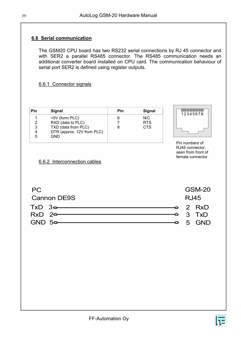
6.6 Serial communication
The GSM20 CPU board has two RS232 serial connections by RJ 45 connector andwith SER2 a parallel RS485 connector. The RS485 communication needs anadditional converter board installed on CPU card. The communication behaviour ofserial port SER2 is defined using register outputs.
6.6.1 Connector signals
6.6.2 Interconnection cables
Pin Signal Pin Signal
1 +5V (form PLC)2 RXD (data to PLC)3 TXD (data from PLC)4 DTR (approx. 12V from PLC)5 GND
6 N/C7 RTS8 CTS
Pin numbers ofRJ45 connector,seen from front offemale connector
1 2 3 4 5 6 7 8
TxD 3RxD 2GND 5
Cannon DE9S RJ45GSM-20
2 RxD3 TxD5 GND
PC
FF-Automation Oy
AutoLog GSM-20 Hardware Manual 40
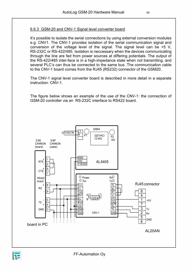
6.6.3 GSM-20 and CNV-1 Signal level converter board
It’s possible to isolate the serial connections by using external conversion modulese.g. CNV1. The CNV-1 provides isolation of the serial communication signal andconversion of the voltage level of the signal. The signal level can be +5 V,RS-232C or RS-422/485. Isolation is neccessary when the devices communicatingthrough the line are fed from power sources at differing potentials. The output ofthe RS-422/485 inter-face is in a high-impedance state when not transmiting, andseveral PLC’s can thus be connected to the same bus. The communication cableto the CNV-1 board comes from the RJ45 (RS232) connector of the GSM20.
The CNV-1 signal level converter board is described in more detail in a separateinstruction: CNV-1.
The figure below shows an example of the use of the CNV-1: the connection ofGSM-20 controller via an RS-232C interface to RS422 board.
AL20ANboard in PC

AutoLog GSM-20 Hardware Manual
FF-Automation Oy
41
6.6.4 AL20AN and CNV-2 Signal level converter board
It’s possible to isolate the serial connections by using external conversion modulese.g. CNV-2. The CNV-2 provides isolation of the serial communication signal andconversion of the voltage level of the signal. The input signal level from PLC is+5 V RS-232C. Isolation is neccessary when the devices communicating throughthe line are fed from power sources at differing potentials. The CNV-2 output to thebus is RS-485 inter-facing high-impedance state when not transmiting, and severalPLC’s can thus be connected to the same bus. The communication/power cable tothe CNV-2 board comes from the RJ45 (RS232) connector of the AL20AN.
The figure below shows an example of the use of the CNV-2: the connection ofAL20AN controller(s) via RS485/RS-232C interface to PC.
MorePLCs
PC
AL20AN
AL20AN
RxDTxD
CNV-2
RxDTxD
CNV-2
RxDTxD
CNV-2
FF-Automation Oy
AutoLog GSM-20 Hardware Manual 42
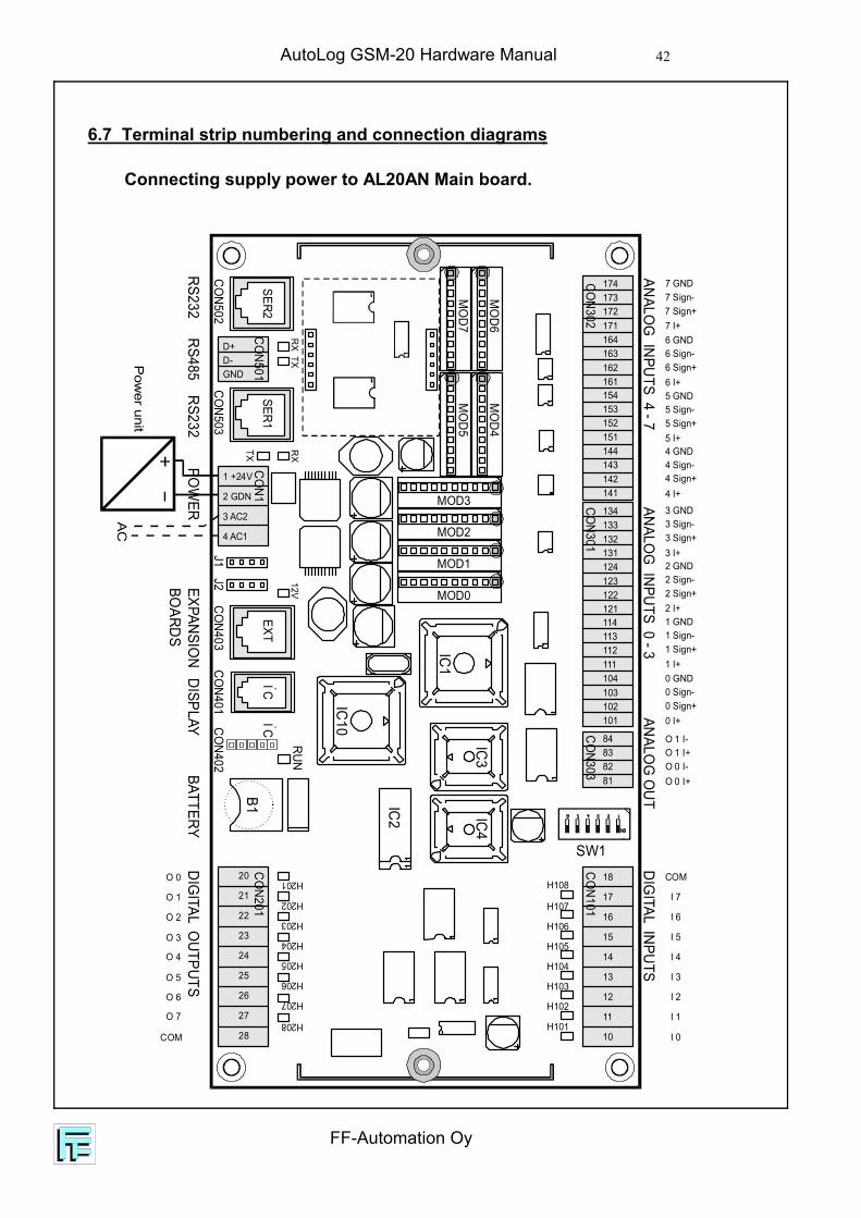
6.7 Terminal strip numbering and connection diagrams
Connecting supply power to AL20AN Main board.
174
134
154
114
173
133
153
113
172
132
152
112
171
131
151
111
164
124
144
104
84
163
123
143
103
83
162
122
142
102
82
161
121
141
101
81
18
17
16
15
14
13
12
11
10
20
21
22
23
24
25
26
27
28
1 +24V
2 GDN
3 AC2
4 AC1
D+D-GND
IC1
IC3IC4
IC2
B1
IC10
TX
MO
D6M
OD4
MO
D7M
OD5
MOD3
MOD2
MOD1
MOD0TX
RXRX
12V
CON303
CON101
CON201
CON1
CON403
CON503J1
J2CO
N502
CON501SER1
SER2
CON401CO
N402
CON301
CON302
RUN
EXTIC 2
IC 2
DIGITAL INPUTS
DIGITAL O
UTPUTSEXPANSIO
NBO
ARDSDISPLAY
BATTERYPO
WER
RS232RS485
RS232
ANALOG
INPUTS 4 - 7ANALO
G INPUTS 0 - 3
SW1
ANALOG
OUT
O 0
O 1
O 2
O 3
O 4
O 5
O 6
O 7
COM
COM
0 Sign-
4 Sign-
2 Sign-
6 Sign-
1 Sign-
5 Sign-
3 Sign-
7 Sign-
O 1 I+
0 Sign+
4 Sign+
2 Sign+
6 Sign+
1 Sign+
5 Sign+
3 Sign+
7 Sign+
O 0 I-
0 I+
4 I+
2 I+
6 I+
1 I+
5 I+
3 I+
7 I+
O 0 I+
0 GND
4 GND
2 GND
6 GND
1 GND
5 GND
3 GND
7 GND
O 1 I-
I 0
I 1
I 2
I 3
I 4
I 5
I 6
I 7
Pow
er unitA
C
H101
H102
H103
H104
H105
H106
H107
H108H201
H202
H203
H204
H205
H206
H207
H208
AutoLog GSM-20 Hardware Manual
FF-Automation Oy
43
Conn.num.
Definingdevice
Analoginput
Digitalinput
101 Module I + I 08
102 Module AI 00 + I 09
103 Module AI 00 - I 10
104 GND GND
111 Module I + I 11
112 Module AI 01 + I 12
113 Module AI 01 - I 13
114 GND GND
121 Module I + I 14
122 Module AI 02 + I 15
123 Module AI 02 - I 16
124 GND GND
131 Module I + I 17
132 Module AI 03 + I 18
133 Module AI 03 - I 19
134 GND GND
141 Module I + I 20
142 Module AI 04 + I 21
143 Module AI04 - I 22
144 GND GND
151 Module I + I 23
152 Module AI 05 + I 24
153 Module AI 05 - I 25
154 GND GND
161 Module I + I 26
162 Module AI 06 + I 27
163 Module AI 06 - I 28
164 GND GND
171 Module I + I 29
172 Module AI 07 + I 30
173 Module AI 07 - I 31
174 GND GND
Connnum.
Analog output
81 AO 00
82 GND
83 AO 01
84 GND
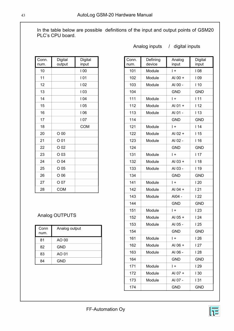
In the table below are possible definitions of the input and output points of GSM20PLC’s CPU board.
Analog inputs / digital inputs
Analog OUTPUTS
Conn.num.
Digitaloutput
Digitalinput
10 I 00
11 I 01
12 I 02
13 I 03
14 I 04
15 I 05
16 I 06
17 I 07
18 COM
20 O 00
21 O 01
22 O 02
23 O 03
24 O 04
25 O 05
26 O 06
27 O 07
28 COM

FF-Automation Oy
AutoLog GSM-20 Hardware Manual 44
Terminal strips of RO16 expansion board.
The possible output numbering variations are shown in chapter 4.2. In the picturebelow are smallest possible output numbers.
Terminal strips of RIO8 expansion board.
The possible output numbering variations are shown in chapter 4.3. In the picturebelow are smallest possible input and output numbers.
15B
15A
14B
14A
13B
13A
12B
12A
11B
11A
10B
10A
9B 9A 8B 8A 3B 3A 2B 2A 1B 1A 0B 0A7B 7A 6B 6A 5B 5A 4B 4A
K8 K7 K6 K5 K4 K3 K2 K1 K16 K15 K14 K13 K12 K11 K10 K9
C11 C10 C9 C8 C7 C6 C5 C4 C3 C18 C17 C16 C15 C14 C13 C12
FROM CPU
CON1
CON101
H8 H7 H6 H5
J11-2 3-4 ADDR1 1 321 0 480 1 640 0 80
H12
H11
H10
H9H16
H15
H14
H13
H4 H3 H2 H1
CON103 CON102
CON2
TO EXT
IC8IC5 IC6
IC7
CON104
O 40
O 41
O 42
O 43
O 44
O 45
O 46
O 47
O 32
O 33
O 34
O 35
O 36
O 37
O 38
O 39
FROM
CPU
TO E
XT
CON1 CON2
www.FF-Automation.com
J1 1 2 3 4 5 61-2 3-4 5-6 ADDR 1-2 3-4 5-6 ADDR1 1 1 321 1 0 401 0 1 481 0 0 56
0 1 1 640 1 0 720 0 1 800 0 0 88
CO
M17 16 15 14 13 12 11 1023
B23
A22
B22
A21
B21
A20
B20
A
27B
27A
26B
26A
25B
25A
24B
24A
I 39
O 3
9
I 38
O 3
8
I 37
O 3
7
I 36
O 3
6
I 35
O 3
5
I 34
O 3
4
I 33
O 3
3
I 32
O 3
2

AutoLog GSM-20 Hardware Manual
FF-Automation Oy
45
Terminal strips of DI16 expansion board.
The possible input number variations are shown in chapter 4.4. In the picturebelow are smallest possible output numbers.
1
1
HC1C2
FROM
CPU
TO E
XT
CON1 CON2
www.FF-Automation.com
CO
M
CO
M20
820
720
620
520
420
320
220
1
CO
M21
621
521
421
321
221
121
020
9
224
CO
M
232
231
230
229
228
227
226
225
223
222
221
220
219
218
217
J1 1 2 3 4
J1 1-2 ADR 32J1 3-4 ADR 64
O 3
9O
38
O 3
7O
36
O 3
5O
34
O 3
3O
32
O 4
7O
46
O 4
5O
44
O 4
3O
42
O 4
1O
40
O 5
5O
54
O 5
3O
52
O 5
1O
50
O 4
9O
48
O 6
3O
62
O 6
1O
60
O 5
9O
58
O 5
7O
56
Terminal strips of DO32 expansion board.
The possible output number variations are shown in chapter 4.6. In the picturebelow are smallest possible output numbers.
J11-2 3-4 ADDR1 1 321 0 480 1 640 0 80www.FF-Automation.com
GN
D
15 14 13 12 11 10 09 08 GN
D
07 06 05 04 03 02 01 00
FROM
CPU
TO E
XT
CON1 CON2
GN
D
I 47
I 46
I 45
I 44
I 43
I 42
I 41
I 40
GN
D
I 39
I 38
I 37
I 36
I 35
I 34
I 33
I 32

FF-Automation Oy
AutoLog GSM-20 Hardware Manual 46
MO
D101
MO
D103
MO
D102
MO
D104
MO
D107
MO
D105
MO
D108
MO
D106
IC3IC2
JP2
IC101
IC103
IC102
X1
IC1
IC105
RUN
RUN IC 2
IC 2
123122121114113
101
81
131
112
102
82
132
111
103
83
133
104
84
134
124
153152151
164163
171
141
162
172
142
161
173
143
8788
8586
174
144
154
AI34 I–AI34 I+AI34 +COMAI33 I–
AI32 +
AO32+
AI35 +
AI33 I+
AI32 I+
COM
AI35 I+
AI33 +
AI32 I
AO33+
AI35 I
COM
COM
COM
COM
AI37 I–AI37 I+AI37+
COMAI38 I–
AI39+
AI36+
AI38 I+
AI39 I+
AI36 I+
AI38+
AI39 I
AI36 I–
AO35+COM
AO34+COM
COM
COM
COM
Terminal strips of EXA 84 expansion board.
The possible output number variations are shown in chapter 4.7. In the picturebelow are smallest possible input (32 - 39) and output numbers (32 - 35).
1 +2
4V
2 GDN
3 AC2
4 AC1
12V
CON1
CON403J1 J2 CON401 CON402
RUN
EXT I C2
I C2
EXPANSIONBOARDS
DISPLAYPOWER
Power supply connection for expansion boards and DIN modules.
The expansion boards, DIN modules and analog RMS modules gets the 12 VDCpower from CPU board voltages. To connect the 12 VDC voltage for these devicesset the 12 VDC connector jumper to shortcut the pins shown in picture below andcheck that the 12 V indication led shows that voltage is connected.
12 VDC connection jumper

AutoLog GSM-20 Hardware Manual
FF-Automation Oy
47
6.8 IButton cable connection
iButton RJ45
2 SDA 3 BAT 4 GND 5 Vcc 6 GND
≈5 kohm
1 CLK
FF-Automation Oy
AutoLog GSM-20 Hardware Manual 48
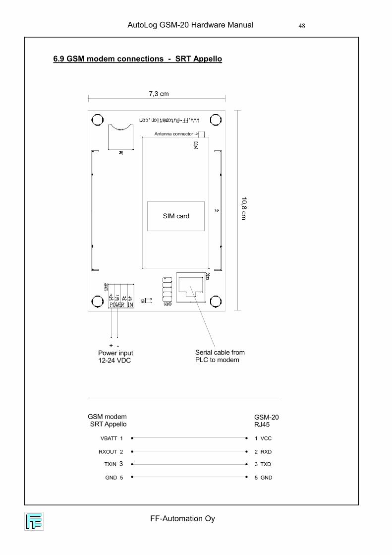
SIM card
+ - Power input12-24 VDC
7,3 cm
10,8 cm
Serial cable fromPLC to modem
Antenna connector ->
GSM modemSRT Appello
GSM-20RJ45
VBATT 1
RXOUT 2
TXIN 3
1 VCC
2 RXD
3 TXD
GND 5 5 GND
6.9 GSM modem connections - SRT Appello
AutoLog GSM-20 Hardware Manual
FF-Automation Oy
49
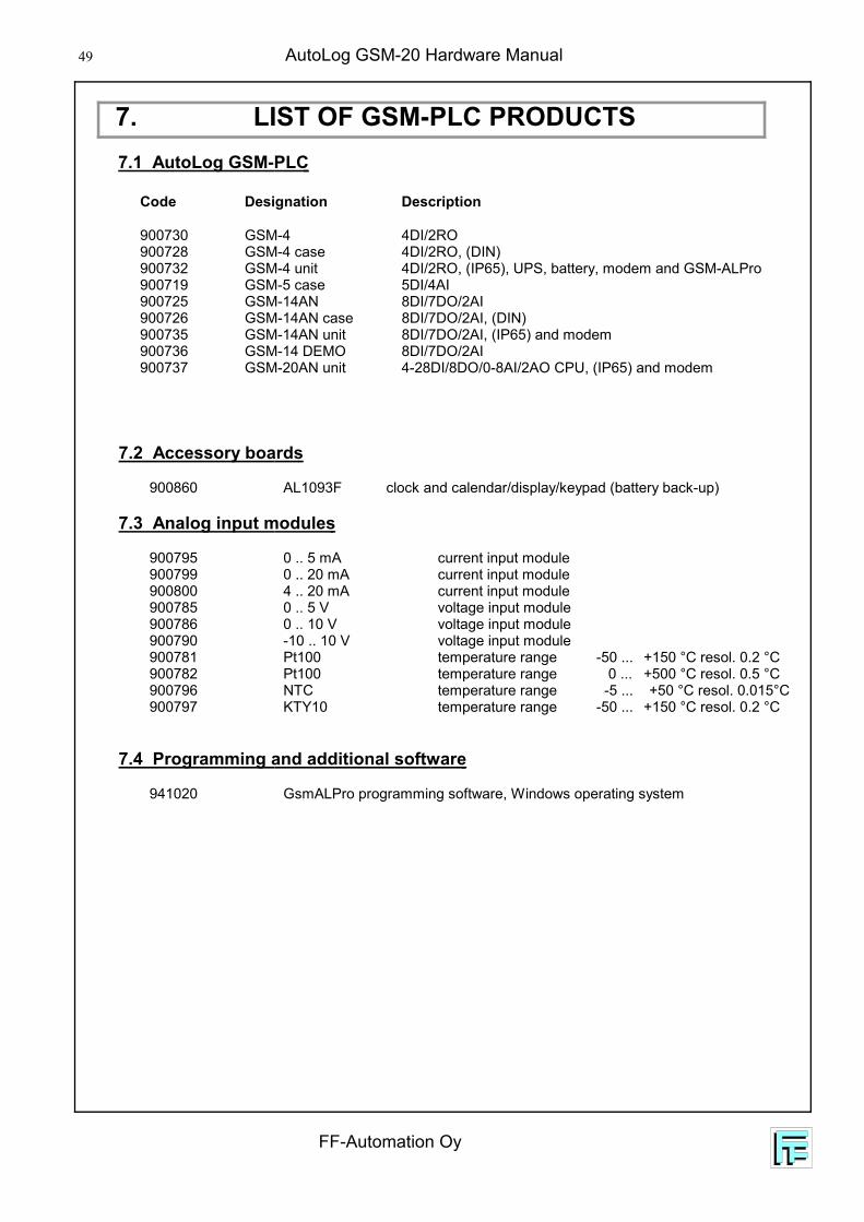
7. LIST OF GSM-PLC PRODUCTS7.1 AutoLog GSM-PLC
Code Designation Description
900730 GSM-4 4DI/2RO900728 GSM-4 case 4DI/2RO, (DIN)900732 GSM-4 unit 4DI/2RO, (IP65), UPS, battery, modem and GSM-ALPro900719 GSM-5 case 5DI/4AI900725 GSM-14AN 8DI/7DO/2AI900726 GSM-14AN case 8DI/7DO/2AI, (DIN)900735 GSM-14AN unit 8DI/7DO/2AI, (IP65) and modem900736 GSM-14 DEMO 8DI/7DO/2AI900737 GSM-20AN unit 4-28DI/8DO/0-8AI/2AO CPU, (IP65) and modem
7.2 Accessory boards
900860 AL1093F clock and calendar/display/keypad (battery back-up)
7.3 Analog input modules
900795 0 .. 5 mA current input module900799 0 .. 20 mA current input module900800 4 .. 20 mA current input module900785 0 .. 5 V voltage input module900786 0 .. 10 V voltage input module900790 -10 .. 10 V voltage input module900781 Pt100 temperature range -50 ... +150 °C resol. 0.2 °C900782 Pt100 temperature range 0 ... +500 °C resol. 0.5 °C900796 NTC temperature range -5 ... +50 °C resol. 0.015°C900797 KTY10 temperature range -50 ... +150 °C resol. 0.2 °C
7.4 Programming and additional software
941020 GsmALPro programming software, Windows operating system
FF-Automation Oy
AutoLog GSM-20 Hardware Manual 50
7.5 Power supplies
901383 AL9624/3.5 Power unit 24VDC/3,5A901380 AL9624/8 Power unit 24VDC/8A902218 AL-UPS AL UPS Module for use with Accumulator901374 AL9624/2/1.5 Power unit 24VDC/2A, 20VAC/1.5A900729 MASCOT power unit 230 VAC/12VDC 0.3 A
7.6 GSM Modems
xxxxxxxx SRT Appello900700 Falcom A2-1 (SMS and data)900710 Ericsson (SMS)900702 Wavecom (SMS and data)900703 GSM Dipole Antenna Dynaflex-586900706 GSM Car Antenna 32 cm Whip900708 900 MHz Whip Antenna
7.7 Programming and auxiliary cables
903195 Programming Cable PC - AL14 Brick (RJ45), Length 2.5m900740 Cable AutoLog 14/20-Falcom GSM900741 Cable AutoLog 14/20-Wavecom GSM900742 Cable AutoLog 14/20-Ericsson GSM
The Manufacturer: FF-Automation OyEräkuja 201600 VANTAAFINLANDPhone 358 9 5306310Fax. 358 9 53063130
AutoLog GSM-20 Hardware Manual
FF-Automation Oy
51
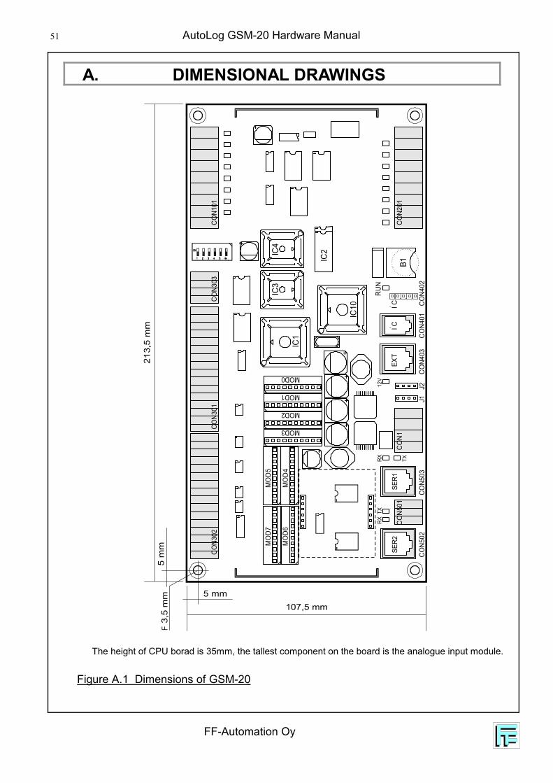
A. DIMENSIONAL DRAWINGS
The height of CPU borad is 35mm, the tallest component on the board is the analogue input module.
Figure A.1 Dimensions of GSM-20
213,
5 m
m5
mm
F 3,
5 m
m
107,5 mm5 mm
IC1
IC3
IC4
IC2
B1
IC10
TX
MO
D7M
OD5
MO
D6M
OD4
MOD3
MOD2
MOD1
MOD0TX
RXRX
12V
CON3
03CO
N101
CON2
01CO
N1
CON4
03CO
N503
J1J2
CON5
02
CON5
01SE
R1SE
R2
CON4
01CO
N402
CON3
01CO
N302
RUN
EXT
IC2
IC2
FF-Automation Oy
AutoLog GSM-20 Hardware Manual 52
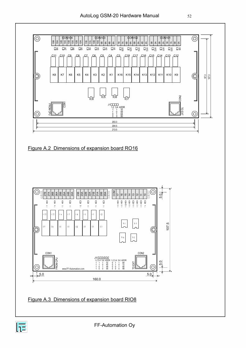
Figure A.2 Dimensions of expansion board RO16
Figure A.3 Dimensions of expansion board RIO8
203.3
97.3
107.3
204.5213.5
15B
15A
14B
14A
13B
13A
12B
12A
11B
11A
10B
10A
9B 9A 8B 8A 3B 3A 2B 2A 1B 1A 0B 0A7B 7A 6B 6A 5B 5A 4B 4A
K8 K7 K6 K5 K4 K3 K2 K1 K16 K15 K14 K13 K12 K11 K10 K9
C11 C10 C9 C8 C7 C6 C5 C4 C3 C18 C17 C16 C15 C14 C13 C12
FROM CPU
CON1
CON101
H8 H7 H6 H5
J11-2 3-4 ADDR1 1 321 0 480 1 640 0 80
H12
H11
H10
H9H16
H15
H14
H13
H4 H3 H2 H1
CON103 CON102
CON2
TO EXT
IC8IC5 IC6
IC7
CON104
160.0
107.
5
5.0
5.0
5.0
5.0
FROM
CPU
TO E
XT
CON1 CON2
www.FF-Automation.com
J1 1 2 3 4 5 61-2 3-4 5-6 ADDR 1-2 3-4 5-6 ADDR1 1 1 321 1 0 401 0 1 481 0 0 56
0 1 1 640 1 0 720 0 1 800 0 0 88
CO
M17 16 15 14 13 12 11 1023
B23
A22
B22
A21
B21
A20
B20
A
27B
27A
26B
26A
25B
25A
24B
24A

AutoLog GSM-20 Hardware Manual
FF-Automation Oy
53
Figure A.4 Dimensions of expansion board DI16
Figure A.5 Dimensions of expansion board DO32
J11-2 3-4 ADDR1 1 321 0 480 1 640 0 80www.FF-Automation.com
GN
D
15 14 13 12 11 10 09 08 GN
D
07 06 05 04 03 02 01 00
FROM
CPU
TO E
XT
CON1 CON2
125,0115,9114,6
107,
597
,3
160.0
107.
5
5.0
5.0
5.0
5.0
1
1
HC1C2
FROM
CPU
TO E
XT
CON1 CON2
www.FF-Automation.com
CO
M
CO
M20
820
720
620
520
420
320
220
1
CO
M21
621
521
421
321
221
121
020
9
224
CO
M
232
231
230
229
228
227
226
225
223
222
221
220
219
218
217
J1 1 2 3 4
J1 1-2 ADR 32J1 3-4 ADR 64
FF-Automation Oy
AutoLog GSM-20 Hardware Manual 54
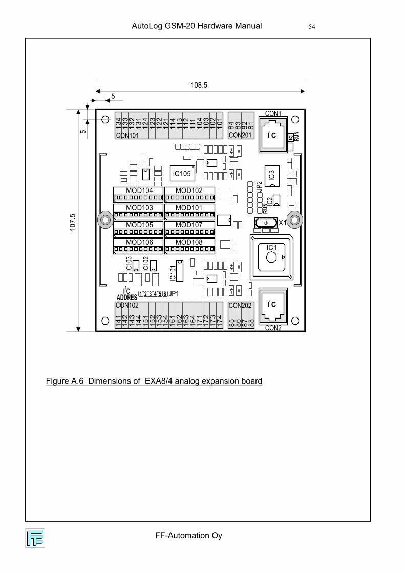
Figure A.6 Dimensions of EXA8/4 analog expansion board
MOD101MOD103
MOD102MOD104
MOD107MOD105
MOD108MOD106
IC3
IC2
JP2
IC10
1IC10
3
IC10
2
X1
IC1
IC105
RUN
RUN
I C2
I C2
123
122
121
114
113
101
81131
112
102
82132
111
103
83133
104
84134
124
153
152
151
164
163
171
141
162
172
142
161
173
143
87 8885 86174
144
154
107.
55
108.55

AutoLog GSM-20 Hardware Manual
FF-Automation Oy
55
Figure A.7 Dimensions of display/keypad unit AL1094
Figure A.8 Dimensions of display/keypad unit 1094R
Led 0Led 1
the key isthe tallestcomponenton the board
174min.17
164
30 7
7464 5
5
80 9
FF-Automation Oy
AutoLog GSM-20 Hardware Manual 56
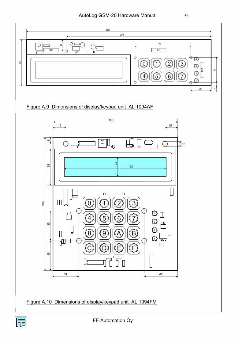
Figure A.9 Dimensions of display/keypad unit AL 1094AF
Figure A.10 Dimensions of display/keypad unit AL 1094FM
1 2 3
5 6 7
0
4
8 9 A B
C D E F1
2
3
4
65
160
8
23150
15 15
6
122
3535
31 40
AutoLog GSM-20 Hardware Manual
FF-Automation Oy
57
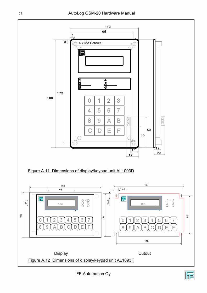
Display CutoutFigure A.12 Dimensions of display/keypad unit AL1093F
Figure A.11 Dimensions of display/keypad unit AL1093D