autocarautocar - 1903 petrol electric autocar · the power unit is now assembled at ummins...
TRANSCRIPT
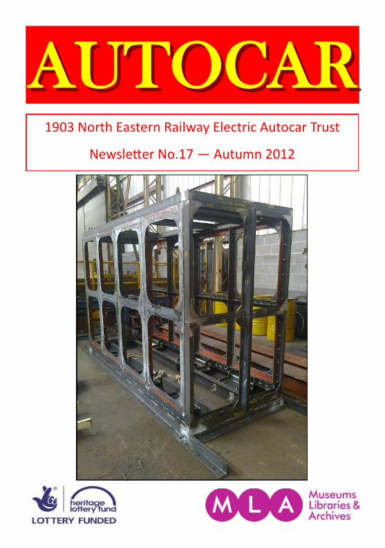
1903 North Eastern Railway Electric Autocar Trust
Newsletter No.17 — Autumn 2012
AUTOCARAUTOCAR
2
The North Eastern Railway 1903 Electric Autocar Trust
Registered Charity No: 1105829
Company Registration No: 05171008 www.electricautocar.co.uk
Chairman
Secretary
Treasurer
Press, Publicity & Editor
Membership
Project Engineer
Front Cover: The engine housing assembly takes shape. (David Moore)
Stephen Middleton, Rose Lea House, 23 Brunswick Drive, Harrogate, North Yorkshire, HG1 2QW. Tel - 01423 561 965 E-mail - [email protected] Dave Cullingworth, 29 Beckett Close, Nawton, York, YO62 7SB. Tel: 01439 771 758 E-mail: [email protected] Peter Lund,
E-mail - [email protected]
Simon Gott, Embsay Station, East Lane, Embsay, Skipton, BD23 6QX. Tel: 07564 249 029 (daytime) E-mail: [email protected] Stuart Hiscock, 2 Lairs Crescent, Snainton, N Yorkshire, YO13 9BQ. Steve Hoather

3
October 2012
Welcome to the 17th issue of our newsletter. We are making good progress on several fronts, with many changes visible on a weekly basis. I would like to thank the engineering team for their various photos which they have sent in, this makes a big difference to the newsletter. After the last issue we received a letter from David Castle, from near Swanage. He was very complimentary about the newsletter and our work on the autocar (thankyou David) and suggested we enclose a flyer for donations. As well as this, his letter prompted us to think about other things, including a correspondence page. So, if you have anything to say or ask, which you feel is suitable for publication, do feel free to write or e-mail in — the details are opposite.
Contents
Chairman’s notes …..…………………………………………………………..
Project Engineer’s report …………………………………………………….
The autocoach ………………………………………………………………..….
Traction design …….…………………………………………………………...
A cousin of the autocar…………………………………….………………...
4
6
10
12
15
Newsletter back issues
Some back copies are available to download from our web-site, if you prefer hard copy, back copies of the newsletter are available from us at £3 each (including postage).
4
Chairman’s notes Stephen Middleton
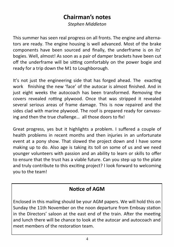
This summer has seen real progress on all fronts. The engine and alterna-tors are ready. The engine housing is well advanced. Most of the brake components have been sourced and finally, the underframe is on its’ bogies. Well, almost! As soon as a pair of damper brackets have been cut off the underframe will be sitting comfortably on the power bogie and ready for a trip down the M1 to Loughborough. It’s not just the engineering side that has forged ahead. The exacting work finishing the new ‘face’ of the autocar is almost finished. And in just eight weeks the autocoach has been transformed. Removing the covers revealed rotting plywood. Once that was stripped it revealed several serious areas of frame damage. This is now repaired and the sides clad with marine plywood. The roof is prepared ready for canvass-ing and then the true challenge… all those doors to fix! Great progress, yes but it highlights a problem. I suffered a couple of health problems in recent months and then injuries in an unfortunate event at a pony show. That slowed the project down and I have some making up to do. Also age is taking its toll on some of us and we need younger volunteers with passion and an ability to learn or skills to offer to ensure that the trust has a viable future. Can you step up to the plate and truly contribute to this exciting project? I look forward to welcoming you to the team!
Notice of AGM Enclosed in this mailing should be your AGM papers. We will hold this on Sunday the 11th November on the noon departure from Embsay station in the Directors’ saloon at the east end of the train. After the meeting and lunch there will be chance to look at the autocar and autocoach and meet members of the restoration team.
5
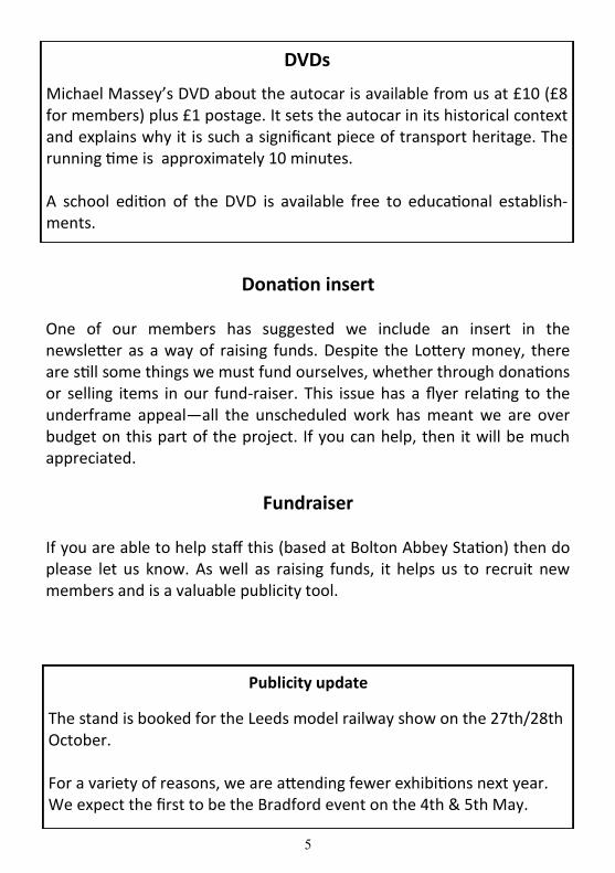
Donation insert
One of our members has suggested we include an insert in the newsletter as a way of raising funds. Despite the Lottery money, there are still some things we must fund ourselves, whether through donations or selling items in our fund-raiser. This issue has a flyer relating to the underframe appeal—all the unscheduled work has meant we are over budget on this part of the project. If you can help, then it will be much appreciated.
Fundraiser If you are able to help staff this (based at Bolton Abbey Station) then do please let us know. As well as raising funds, it helps us to recruit new members and is a valuable publicity tool.
Publicity update
The stand is booked for the Leeds model railway show on the 27th/28th October. For a variety of reasons, we are attending fewer exhibitions next year. We expect the first to be the Bradford event on the 4th & 5th May.
DVDs
Michael Massey’s DVD about the autocar is available from us at £10 (£8 for members) plus £1 postage. It sets the autocar in its historical context and explains why it is such a significant piece of transport heritage. The running time is approximately 10 minutes. A school edition of the DVD is available free to educational establish-ments.
6
Engineering Progress Report
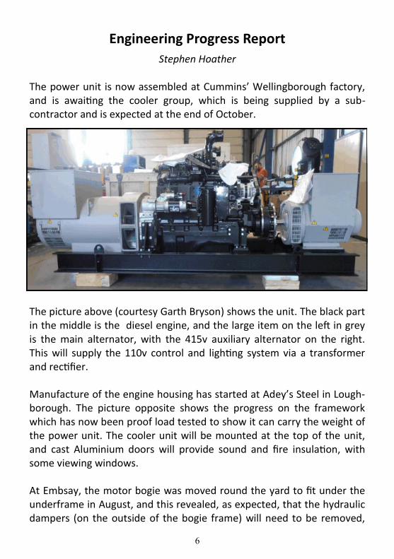
Stephen Hoather The power unit is now assembled at Cummins’ Wellingborough factory, and is awaiting the cooler group, which is being supplied by a sub-contractor and is expected at the end of October.
The picture above (courtesy Garth Bryson) shows the unit. The black part in the middle is the diesel engine, and the large item on the left in grey is the main alternator, with the 415v auxiliary alternator on the right. This will supply the 110v control and lighting system via a transformer and rectifier. Manufacture of the engine housing has started at Adey’s Steel in Lough-borough. The picture opposite shows the progress on the framework which has now been proof load tested to show it can carry the weight of the power unit. The cooler unit will be mounted at the top of the unit, and cast Aluminium doors will provide sound and fire insulation, with some viewing windows. At Embsay, the motor bogie was moved round the yard to fit under the underframe in August, and this revealed, as expected, that the hydraulic dampers (on the outside of the bogie frame) will need to be removed,

7
and the side bearers on the motor bogie modified to suit the under-frame. Unfortunately this involves lifting the underframe again, and the jacks are now in use for changing a wheelset on one of the steam locos, so there will be some delay but this is not critical. An area of concern is that the truss rods look as if they will be very close to the lever on the brake cross shaft which is mounted on the inner headstock of the motor bogie. We will not know whether this is a real problem until we can load the end of the underframe to deflect the springs as they will be when the engine and body are fitted, but at worst this may mean we will need to reposition the truss rod anchor brackets on the solebar.
Detail design work on the underframe reinforcing plates is proceeding, and the first batch of calculations has been passed to the Independent Engineer for review. We will not start manufacture until the Independent Engineer is satisfied they are fit for purpose. All the axles had a UAT (Ultrasonic Axle Test) recently and passed.
Engine housing assembly (Dave Moore)
8
On the brakes front, the first batch of pneumatic components is now at our contractor’s workshop in Burton on Trent for overhaul. We think we have now found a source of supply for virtually all the major components we still need (including the 12” brake cylinder) apart from what is known as a Westinghouse Brake Application unit. These are fitted to main line locos such as classes 31 and 37 which have Westinghouse brake systems, and we are making enquiries of the owners of these to see if there are any spare units available. For the trailer car, I recently went to the Search Engine at the NRM to look for a drawing of the underframe, as this will assist design work for the Dual brake conversion. I found two possible drawings which differ only in the sizes of the timber headstocks and transoms. We will check these drawings against the vehicle shortly, but even if they are the correct ones their use will be limited as they show the vehicles as built with air brakes (and gas tanks for the lighting!) The brake layout was completely altered when the coaches were converted to vacuum, and since we intend to retain the vacuum with its V hangers and add air cylinders, I will need to obtain a drawing of the conversion work once I have established the basic drawing. The wheel goes full circle!!
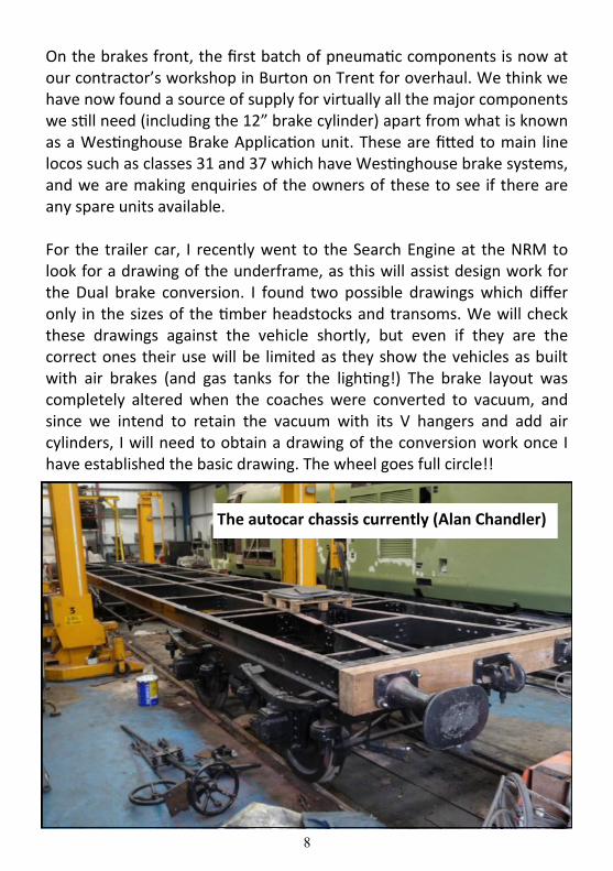
The autocar chassis currently (Alan Chandler)

9
The engine housing assembly under load testing. It needs to be capable of being lifted with the power unit inside. (Peter Van Houten).

10
The Autocoach Stephen Middleton
We started work on the autocoach (trailer) in summer, once it was under cover. The plywood panels came away in our hands revealing several critical frame repair jobs, notably three corner posts, a cant rail and bottom side. There was no rot, just splits where some metal bolts had corroded. Much of the work was needed around the cab end where the conversion work (turning the coach from a third class into a driving com-posite brake) took place. Replacement drop light frames replaced the shabby old ones. The roof is stripped off ready for canvassing and the torpedo vents painted. Two of the worst doors have been repaired and several components, including vent hoods and window beads, taken away for paint stripping. All the timber needed for beading, gutters etc. have been ordered and once the top line of beads are fitted we can canvass the roof.
(SM)
11
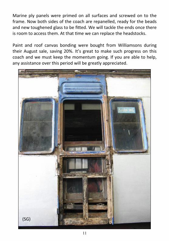
Marine ply panels were primed on all surfaces and screwed on to the frame. Now both sides of the coach are repanelled, ready for the beads and new toughened glass to be fitted. We will tackle the ends once there is room to access them. At that time we can replace the headstocks. Paint and roof canvas bonding were bought from Williamsons during their August sale, saving 20%. It’s great to make such progress on this coach and we must keep the momentum going. If you are able to help, any assistance over this period will be greatly appreciated.
(SG)
12
An Engineer’s Perspective — Traction design (continued)
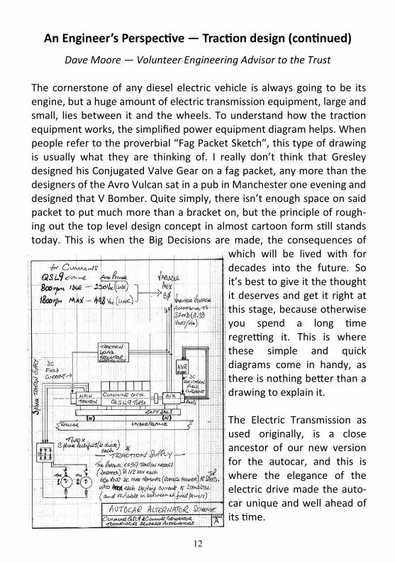
Dave Moore — Volunteer Engineering Advisor to the Trust The cornerstone of any diesel electric vehicle is always going to be its engine, but a huge amount of electric transmission equipment, large and small, lies between it and the wheels. To understand how the traction equipment works, the simplified power equipment diagram helps. When people refer to the proverbial “Fag Packet Sketch”, this type of drawing is usually what they are thinking of. I really don’t think that Gresley designed his Conjugated Valve Gear on a fag packet, any more than the designers of the Avro Vulcan sat in a pub in Manchester one evening and designed that V Bomber. Quite simply, there isn’t enough space on said packet to put much more than a bracket on, but the principle of rough-ing out the top level design concept in almost cartoon form still stands today. This is when the Big Decisions are made, the consequences of
which will be lived with for decades into the future. So it’s best to give it the thought it deserves and get it right at this stage, because otherwise you spend a long time regretting it. This is where these simple and quick diagrams come in handy, as there is nothing better than a drawing to explain it. The Electric Transmission as used originally, is a close ancestor of our new version for the autocar, and this is where the elegance of the electric drive made the auto-car unique and well ahead of its time.

13
The engine and the vehicle need electrical life support from the moment the engine is started. That’s where the auxiliary alternator comes in. Always the smaller, it provides electrical power for charging the vehicle batteries and sustaining the vehicle’s electrical system through the run-ning day, including the unpowered autocoach. The use of alternating current (AC) alternators is standard modern practice now that conven-tional direct current generators (DC) are almost impossible to obtain. The alternator is a more robust electrical machine anyway, but does henceforth dictate the use of AC equipment to some extent. This is really the post 1970 method of locomotive power generation. The traction equipment also needs to be able to run off the AC produced by the big Traction (or Main) Alternator. This is a complication, in that the English Electric DC Traction Motors cannot run directly from the source of the power, and need Rectifiers to convert the AC into DC for the Motors. Again, this was state of the art in 1970, this configuration became the standard method for diesel electric traction.
The engine sits on a rigid steel sub chassis and is coupled directly to the Traction Alternator. At the other end of the engine is the smaller Auxiliary Alternator, which is driven through a coupling. This complete raft is not bolted directly to the vehicle underframe, but is seated on anti-vibration mounts, mainly to isolate the engine vibration from the vehicle so as to give a more comfortable ride, with lower levels of noise and vibration in the carbody. The AC power from the two alternators is in the form of a variable frequency (because the engine speed varies) and variable voltage, 3 phase supply. This bears a resemblance to normal industrial 415 volts, 50 Hz power supplies, but is tailored to suit the rail traction requirement. The Auxiliary 3 phase is either used directly, such as powering the radiator fan, or converted into DC for powering the locomotive style 110 volt DC control equipment that operates through-out the autocar & autocoach two car unit. Up to 50 kW is available from the Auxiliary Alternator. The Traction 3 phase power feeds the DC Traction Motors through Rectifier Units, with a Contactor (power switch) to connect each motor in circuit.

14
The control and regulation of the 3 phase auxiliary power is implement-ed by the Automatic Voltage Regulator (AVR), and the control of the traction supply is done by the Load Regulator. Both units are electronic and operate by controlling the excitation (field) currents in their respec-tive alternators. The Traction Alternator is unusual in that it has to provide high current at low voltage for starting the autocar, and then provides low current at high voltage at higher speeds. This is quite unlike what is required of conventional power supplies and alternators, and thus the autocar electrical machines are specially sourced for this application, worked out for the worst case scenario so the equipment will always be operating within its operating limits. (This worst case is restarting a fully loaded autocar and trailer on the 1:49 gradient between Grosmont and Goathland on the NYMR).
The Alternator duty diagram shows a typical worst (most difficult) duty graphically, drawn to evaluate the required Traction Alternator capacity.
15
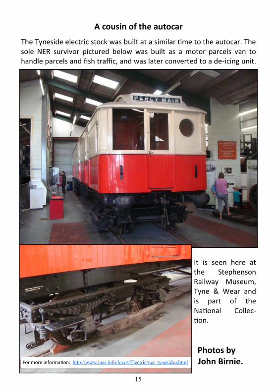
A cousin of the autocar
The Tyneside electric stock was built at a similar time to the autocar. The sole NER survivor pictured below was built as a motor parcels van to handle parcels and fish traffic, and was later converted to a de-icing unit.
It is seen here at the Stephenson Railway Museum, Tyne & Wear and is part of the National Collec-tion.
Photos by John Birnie. For more information: http://www.lner.info/locos/Electric/ner_tyneside.shtml
16
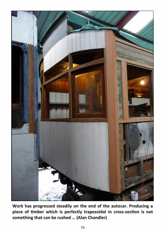
Work has progressed steadily on the end of the autocar. Producing a piece of timber which is perfectly trapezoidal in cross-section is not something that can be rushed … (Alan Chandler)