autocad 2007 preview guide
TRANSCRIPT

www.autodesk.com/autocad
AutoCAD® 2007
Preview Guide
Design, visualize, and document your ideas clearly and efficiently with AutoCAD® software. From conceptual design through drafting and detailing, AutoCAD 2007 enables you to explore ideas like never before.

AUTOCAD 2007 PREVIEW GUIDE
2
Contents Introduction ...................................................................................................................... 4 Design Your Ideas ............................................................................................................ 4
Using Conceptual Design Tools ................................................................................... 4 Accessing Conceptual Design Tools ........................................................................ 4 Setting Conceptual Design Options.......................................................................... 5 Designing with Dynamic Feedback .......................................................................... 6 Changing Workplanes .............................................................................................. 6 Tracking Object Snaps ............................................................................................. 7 Designing and Drafting with Consistency ................................................................. 7
Creating Solids and Surfaces ....................................................................................... 8 Creating Pyramidal Solids ........................................................................................ 8 Creating Helical Shapes........................................................................................... 8 Extruding 2D Geometry............................................................................................ 8 Revolving 2D Geometry ........................................................................................... 9 Sweeping Profiles Along a Path ............................................................................. 10 Lofting Surfaces Between Profiles.......................................................................... 10 Creating 3D Polylines............................................................................................. 11 Creating Planar Surfaces ....................................................................................... 11 Slicing Solids with Surfaces.................................................................................... 11
Converting to Solids and Surfaces.............................................................................. 12 Thickening Surfaces into Solids ............................................................................. 12 Converting Thick 2D Objects to Solids ................................................................... 12 Converting 2D Objects to Surfaces ........................................................................ 12 Exploding Solids and Surfaces............................................................................... 12 Extracting Wireframe Geometry from Solids, Regions, and Surfaces .................... 12
Manipulating Solids and Surfaces............................................................................... 12 Editing Solids.......................................................................................................... 12 Checking for Interferences ..................................................................................... 13 Aligning Objects ..................................................................................................... 14
Visualize Your Ideas....................................................................................................... 14 Viewing Conceptual Designs ...................................................................................... 14
Navigating the Design ............................................................................................ 14 Swiveling the viewpoint .......................................................................................... 15 Creating cameras ................................................................................................... 15

AUTOCAD 2007 PREVIEW GUIDE
3
Creating a walk-through ......................................................................................... 15 Changing Projection Modes ................................................................................... 16
Rendering Conceptual Designs .................................................................................. 17 Applying Lighting .................................................................................................... 17 Applying Materials .................................................................................................. 17
Applying Visual Styles ................................................................................................ 18 Document Your Ideas..................................................................................................... 20
Defining Section Planes.............................................................................................. 20 Flattening a View ........................................................................................................ 21
Share Your Ideas ............................................................................................................ 22 Working with DWF Files ............................................................................................. 22 Plotting to PDF ........................................................................................................... 24 Working with Reference Files ..................................................................................... 24 Saving to Older File Formats ...................................................................................... 24
Additional Customer Requests ..................................................................................... 25

AUTOCAD 2007 PREVIEW GUIDE
4
Introduction Create, edit, and develop design alternatives using realistic solids and surfaces in an updated design environment. Communicate your ideas with powerful sketch, shadow, and rendering tools, including intuitive walk-through animations. Then turn your concepts into a set of documents with the new section and flatten functionality. It’s all here, whether you’re creating, exploring, managing, or communicating, AutoCAD keeps you on time, on budget, and on track.
Figure 1. Conceptual design and construction drawings
Design Your Ideas The first step in realizing your ideas is to create them! You need design tools that enable you to transfer ideas from your mind to the drawing with minimal effort and disruption to your creative process. You want tools that are easy to find and access, with minimal picks and maximum automation. You don’t want to draw by trial and error. Instead, you want dynamic visual feedback providing assurance that the design in the drawing matches the idea in your head. The process for creating conceptual designs should be intuitive, taking advantage of your existing AutoCAD knowledge. You can efficiently create your ideas in AutoCAD 2007 by taking advantage of new and enhanced functionality for:
• Using Conceptual Design Tools
• Creating Solids and Surfaces
• Converting to Solids and Surfaces
• Manipulating Solids and Surfaces.
Using Conceptual Design Tools
Accessing Conceptual Design Tools AutoCAD 2007 includes a new palette, called Dashboard, to help centralize the many conceptual design tools. You can access the Dashboard by enabling it from the Tools>Palettes>Dashboard menu option or by entering the DASHBOARD command. The Dashboard includes various control panels with tools for creating, editing, and viewing your conceptual designs. A right-click menu enables you to display any combination of the control panels including:

AUTOCAD 2007 PREVIEW GUIDE
5
• 2D Draw control panel
• 3D Make control panel
• 3D Navigate control panel
• Light control panel
• Visual Style control panel
• Materials control panel
• Render control panel
Figure 2. Dashboard
You can resize, dock, and Auto-hide the Dashboard and you can expand some sections of the Dashboard to access more options.
Figure 3. Expanding the Dashboard.
Setting Conceptual Design Options A new 3D Modeling tab has been added to the Options dialog box. On this tab you will find many options for controlling your conceptual design environment. You can:
• Customize the appearance of the 3D crosshairs
• Specify when to display the UCS ICON

AUTOCAD 2007 PREVIEW GUIDE
6
• Enable the Z-field for pointer input.
• Apply visual styles.
• Specify object deletion behavior for profiles and other defining geometry.
• Specify the number of U and V lines on surfaces and meshes.
• Reverse the behavior of the mouse wheel zoom.
• Specify the navigation settings for walk-throughs and animations.
Figure 4. Controlling the conceptual design environment.
Designing with Dynamic Feedback New dynamic geometric feedback enables you to visualize the objects in your conceptual design while you draw. For example, as you draw a box in AutoCAD 2007, the size, shape, and location of the box dynamically displays in the drawing. You can enter dimensions using Dynamic Input or you can drag the cursor to visually specify the length, width, and height.
Figure 5. Creating a box.
Changing Workplanes New Dynamic UCS functionality automatically switches your current workplane reducing the need for you to manually change your UCS. The Dynamic UCS is enabled by default

AUTOCAD 2007 PREVIEW GUIDE
7
and you can toggle it on or off with the DUCS option on the status bar. With DUCS enabled, you can pass your cursor over the edge of a face; the face will highlight indicating that it is being used to establish a temporary UCS.
Figure 6. Switching workplanes dynamically.
Tracking Object Snaps Drawing aids have been enhanced in AutoCAD 2007, offering more powerful functionality for conceptual design as well as 2D drafting. When tracking from an acquired point, you can view and edit the distance using dynamic input functionality and direct distance entry. AutoTracking and Object snaps have been enhanced to detect and track in the Z direction. Even in Perspective mode!
Figure 7. Tracking objects along the Z-axis
Designing and Drafting with Consistency In AutoCAD 2007 you can design solid primitives in an intuitive manner taking advantage of your familiarity with 2D AutoCAD drafting tools. For example, when you begin drawing a circular solid such as a cylinder, cone, sphere, or torus, the process is similar to creating a circle and when you begin drawing a rectangular solid such as a box or a wedge, the process is similar to creating a rectangle.
Figure 8. Creating cylinders and circles.

AUTOCAD 2007 PREVIEW GUIDE
8
Creating Solids and Surfaces
Creating Pyramidal Solids The new PYRAMID command in AutoCAD 2007 enables you to draw a solid pyramid primitive as easily as drawing a polygon. You can specify the number of sides, base radius or edge, top radius, and height to create a variety of pyramidal shapes.
Figure 9. Pyramidal solids
Creating Helical Shapes One of the most challenging shapes to create is a helix, yet you find helical shapes in many objects including springs, screws, coils, and even slides. But how do you create these complex shapes in the AutoCAD software application? In AutoCAD 2007, it’s easy! You can easily create a wireframe helix by specifying the height, base and top radii, number of turns, height of turns, and direction (clockwise or counter clockwise).
Figure 10. Helical wireframes
After you create a wireframe helix, you can use it as a path for a 2D profile enabling you to create a variety of helical shapes.
Figure 11. Doorstop created using a helical path
Extruding 2D Geometry The EXTRUDE command has been updated in AutoCAD 2007, to create either surfaces or solids based on the original profile. Extruding open geometry produces surfaces and extruding closed geometry produces solids. You can select multiple 2D objects (open and closed) in one operation and AutoCAD will automatically produce the appropriate shape.

AUTOCAD 2007 PREVIEW GUIDE
9
Furthermore, you can specify the extrusion direction and distance of a selected profile by dragging your cursor and dynamically viewing the resulting shape.
Figure 12. Extruding a profile.
In addition to extruding a 2D profile, you can use the face of an existing solid or surface to create a new solid. When prompted to select the objects to extrude, press the CTRL key and select a face.
Figure 13. Extruding a face.
Revolving 2D Geometry The REVOLVE command has been updated to produce either surfaces or solids based on the profile and axis of rotation. Using the REVOLVE command on a closed 2D profile will produce a solid. Using the REVOLVE command on an open 2D profile will produce a surface unless the axis of revolution “closes” the profile. For example, if you revolve an arc about an axis that “closes” the arc, it will produce a solid. However, if you push that axis out just a little, it will produce a surface.
Figure 14. Creating solids and surfaces based on the axis of revolution.
In addition to revolving a 2D profile, you can use the face of an existing solid or surface to create a new solid. When prompted to select the objects to revolve, press the CTR key and select a face.

AUTOCAD 2007 PREVIEW GUIDE
10
Figure 15. Revolving a face.
Sweeping Profiles Along a Path The new SWEEP command in AutoCAD 2007 provides considerable flexibility for sweeping profiles along a path. It can automatically align a profile with a path and you can specify a variety of options including scale factor, twist angle, and banking. Depending if the profile is an open or closed curve, the SWEEP command will create a surface or solid. Combining the sweep options with the flexibility of paths and profiles, the design possibilities are virtually endless.
Figure 16. Swept surfaces.
Lofting Surfaces Between Profiles The new LOFT command in AutoCAD 2007 interpolates a surface or solid through a set of cross section curves. If the cross section curves are open, AutoCAD 2007 creates a surface and if they are closed, it creates a solid. You can select any number of cross sections and the order in which you select the cross sections affects the results.
Figure 17. Creating a lofted surface.
A Settings option provides access to the Loft Settings dialog box where you can specify how the surface should behave at the cross sections.

AUTOCAD 2007 PREVIEW GUIDE
11
Figure 18. Loft Settings dialog box.
Creating 3D Polylines The new POLYSOLID command enables you to specify the length, width, and justification of a rectangular profile and then draw the path, similar to drawing a Polyline. You can access familiar Polyline options including Arc, Undo, and Close and the geometry dynamically displays as you draw.
Figure 19. Polysolids.
If you already have a path, you can use the Object option in the POLYSOLID command to sweep a rectangular profile, with the specified height and width, along the path.
Creating Planar Surfaces The new PLANESURF command enables you to create an accurate planar surface with minimal effort. You can pick a rectangular area or use the Object option to select one or more objects that form an enclosed area.
Figure 20. Surfaces created with the PLANESURF command.
Slicing Solids with Surfaces The SLICE command has been updated in AutoCAD 2007 to enable you to select a surface as the slicing object.

AUTOCAD 2007 PREVIEW GUIDE
12
Figure 21. Slicing a solid with a surface.
Converting to Solids and Surfaces
Thickening Surfaces into Solids In AutoCAD 2007 you can use the new THICKEN command to add thickness to a surface, turning it into a solid.
Figure 27. Thickening surfaces into solids.
Converting Thick 2D Objects to Solids The new CONVTOSOLID command in AutoCAD 2007 enables you to convert a 2D object with thickness into an equivalent extruded solid.
Converting 2D Objects to Surfaces The new CONVTOSURFACE command enables you to converts a variety of objects into surfaces.
Exploding Solids and Surfaces The EXPLODE command will explode solids into regions and surfaces. Planar faces of solids are converted into regions, and curved faces of solids are converted into surfaces.
Extracting Wireframe Geometry from Solids, Regions, and Surfaces The new XEDGES command enables you to extract wireframe geometry from solids, surfaces and regions.
Manipulating Solids and Surfaces
Editing Solids The Properties Palette has been updated to support new 3D functionality. It is particularly useful as you explore your design ideas because you can easily view and edit a variety of 3D object properties. For a graphical approach to editing, simply select the object! Depending on the type of 3D object, various grips will display enabling you to directly manipulate its size and shape.

AUTOCAD 2007 PREVIEW GUIDE
13
Figure 22. Editing Solids.
AutoCAD 2007 offers additional editing flexibility by enabling you to select a face or edge within a solid. Press the CTRL key as you pass your cursor over the various components of the solid. When the correct face or edge is highlighted, select it and launch the editing command!
Figure 23. Moving the edge or face of a solid.
Checking for Interferences The INTERFERE command has been updated to make it easier for you to identify when solids interfere with each other. It also includes the ability to select blocks and external references when searching for interferences and to select individual nested solids within a block or xref.

AUTOCAD 2007 PREVIEW GUIDE
14
Aligning Objects The ALIGN command has been updated so you can dynamically see the selected geometry align as you specify the destination points. You first select all of the base points, and then select all of the alignment points!
Visualize Your Ideas After you create your conceptual design, you can use it to communicate your ideas to clients, consultants, review committees, and anyone else with a stake in the project. AutoCAD 2007 provides a variety of intuitive tools that enable you to efficiently and effectively communicate your design intent.
Viewing Conceptual Designs
Navigating the Design The 3DORBIT command enables you to orbit around your design with more control. The new default, Constrained Orbit mode, prevents you from inadvertently rolling the geometry completely over. You can easily orbit around the geometry but if you orbit above or below, it stops when you reach the top or bottom (North or South Pole). An alternate method for accessing constrained orbit, without even launching a command, is to press the Shift key and middle mouse button.
Figure 24. Constrained Orbit.
If you want the ability to spin the view without constraints, you can use the Free Orbit mode.
Figure 25. Free Orbit.
Regardless of which Orbit mode you select, you can press the Shift key to access the arcball for legacy orbit behavior.

AUTOCAD 2007 PREVIEW GUIDE
15
Figure 26. Pressing the Shift key in 3D ORBIT.
Swiveling the viewpoint The new 3DSWIVEL command enables you to maintain your position while spinning your viewpoint; similar to spinning a camera on a tripod. You might use the SWIVEL command to look around the interior of a room, while you would use the ORBIT command to fly around the outside of the building.
Figure 27. Swiveling the viewpoint.
Creating cameras The CAMERA command enables you to create cameras for viewing your design. You define a camera by specifying the location and target. Additional options enable you to specify the camera’s name, height, lens size, and clipping planes. AutoCAD inserts a camera icon and automatically creates a corresponding named view. You can easily restore the camera’s view using the drop-down list in the Navigation control panel of the Dashboard. And you can manipulate existing camera properties using grips or the Properties palette.
Figure 28. Creating a camera.
Creating a walk-through The new 3DWALK command enables you to walk through your design using the arrow keys as well as the W,A,S, and D keys. A position locator displays the camera and target positions enabling you to graphically edit them by dragging the indicator icons.

AUTOCAD 2007 PREVIEW GUIDE
16
Figure 29. Creating a walk-through.
Using the expanded navigation controls in the dashboard, you can adjust the step size and speed as well as the camera and target locations. Recording tools enable you to record the screen as you walk through your design and save the animation to AVI, MPG, or WMV format for future playback.
Figure 30. Controlling navigation.
Changing Projection Modes You can easily toggle between Parallel and Perspective projections by selecting the appropriate buttons on the Dashboard or by setting the new PERSPECTIVE system variable.
Figure 31. Changing projection modes.

AUTOCAD 2007 PREVIEW GUIDE
17
Rendering Conceptual Designs
Applying Lighting In AutoCAD 2007, new light tools enable you to create and manipulate lighting effects for realistic renderings. You can create point, spot, and distant and then edit their properties by editing the grips on the light object or using the properties palette. All of your lights are displayed in the new LIGHTLIST window for easy viewing.
Figure 32. Creating lights.
Applying Materials A new materials library in AutoCAD 2007 enables you to easily apply realistic materials to your conceptual designs. The materials library is accessible from new tabs in the Tool Palettes window where you can view swatches of the materials and then drag and drop them onto individual faces in your design. You can edit the properties of materials in the current drawing using the Materials editor which is accessible from the Materials control panel of the Dashboard.

AUTOCAD 2007 PREVIEW GUIDE
18
Figure 33. Using the Materials palette.
Additional tools in the Dashboard enable you to control the visibility of materials and textures, control the mapping of materials, and associate a material with all the geometry on a layer.
Figure 34. Applying materials.
Applying Visual Styles New Visual Styles in AutoCAD 2007 enable you to quickly change the appearance of your model. They replace the previous shademode functionality and provide even greater control and flexibility. You can apply a variety of properties to affect the opacity, background, shadows, edges, faces and more.
Figure 35. Viewing a model with different visual styles.
A Visual Styles Manager enables you to create and modify named visual styles so that you can easily apply any style at any time. You can access the visual Styles Manager from the Visual Styles control panel of the Dashboard. An image pane enables you to preview and select named visual styles.

AUTOCAD 2007 PREVIEW GUIDE
19
Figure 36. Modifying a visual style.
If you want to change the visual properties of the current viewport without affecting the saved visual style, you can use the tools in the Visual Styles control panel of the Dashboard.
Figure 37. Applying Visual Styles.
AUTOCAD 2007 PREVIEW GUIDE
20
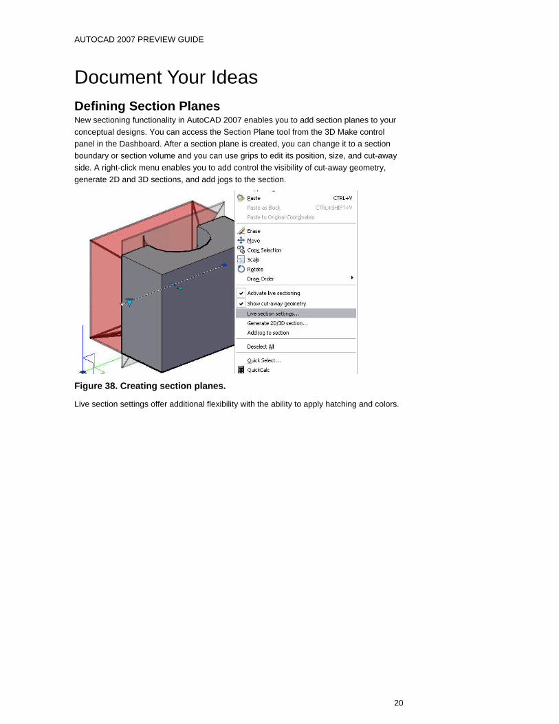
Document Your Ideas Defining Section Planes New sectioning functionality in AutoCAD 2007 enables you to add section planes to your conceptual designs. You can access the Section Plane tool from the 3D Make control panel in the Dashboard. After a section plane is created, you can change it to a section boundary or section volume and you can use grips to edit its position, size, and cut-away side. A right-click menu enables you to add control the visibility of cut-away geometry, generate 2D and 3D sections, and add jogs to the section.
Figure 38. Creating section planes.
Live section settings offer additional flexibility with the ability to apply hatching and colors.

AUTOCAD 2007 PREVIEW GUIDE
21
Figure 39. Modifying section settings.
Flattening a View The new FLATSHOT command enables you to create 2D line drawings based on the current view of your conceptual design. You can create the new 2D drawing as a block definition or as an external DWG file. You have the option to show obscured lines and you can specify the color and linetype.

AUTOCAD 2007 PREVIEW GUIDE
22
Figure 40. Using FLATSHOT to create a 2D line drawing.
Share Your Ideas AutoCAD drawing files created in the DWG format contain critical design information that you may need to share with design partners. However, sharing the DWG files themselves can be cumbersome and risky. DWG files can be large with many references and you must “trust” that the recipient of your DWG files will not edit the design data you have provided. Using the DWF™ file specification, though, enables you to share your AutoCAD drawing data in a secure, highly compressed vector-based format.
Working with DWF Files AutoCAD 2007 combines the security and compression of DWF with the reference concept of xrefs and images. The new DWFATTACH command displays the Attach DWF Underlay dialog box where you can specify the path type, scale, insertion point, and rotation to attach a DWF file. If you attempt to attach a DWF file that is password protected, you will be prompted to enter the password.

AUTOCAD 2007 PREVIEW GUIDE
23
Figure 41. Attaching a DWF Underlay.
After you have attached a DWF file, you can modify its appearance. The DWFADJUST command and the Properties window enable you to set the DWF underlay to monochrome and to adjust its fade and contrast. The Properties window offers an additional property to automatically adjust the DWF colors for the background.
Figure 42. Adjusting the appearance of a DWF underlay.
The DWFCLIP command enables you to specify a clipping boundary to limit the visible area of the DWF underlay and the DWFFRAME system variable displays a selectable frame around the extents of the DWF underlay. The new DWFOSNAP system variable provides control for snapping to geometry within the DWF overlay.

AUTOCAD 2007 PREVIEW GUIDE
24
Figure 43. Adjusting the visible area of a DWF underlay.
AutoCAD 2007 includes additional DWF enhancements to provide greater flexibility for publishing and viewing DWF files. You can publish DWF files with 2D and 3D streams combined or you can use the EXPORT command to create a DWF file with a 3D stream only. To take full advantage of the DWF file enhancements, AutoCAD 2007 includes the updated Autodesk® DWF™ Viewer. The new Viewer includes improved navigation, Microsoft® Office support and Windows® operating system shell integration. You can view 2D and 3D data in the same DWF file, use the new 3D Sectioning and Pull Apart tools for better viewing of your 3D model, and email the DWF directly from the viewer.
Plotting to PDF AutoCAD 2007 includes a new driver that enables you to plot your drawings to PDF. You will find the PDF driver, DWG to PDF.pc3, in the list of devices in the Plot and Page setup dialog boxes.
Working with Reference Files The new EXTERNALREFERENCES command enables you to see all your externally referenced files in a central location. The new External References window displays attached DWG files, images and DWF underlays.
Figure 44. External References window
Saving to Older File Formats If you have upgraded to AutoCAD 2007, you are undoubtedly benefiting from the powerful new and enhanced functionality this release has to offer. However, the hassle of having to exchange files with other project members that have not yet upgraded can cut into the productivity you have gained.

AUTOCAD 2007 PREVIEW GUIDE
25
AutoCAD 2007 enables you to save your drawings down to older formats to facilitate data exchange with other project members. In addition to saving in the current format, you can save your drawings in all DWG formats as far back as AutoCAD® Release 14
Additional Customer Requests Sheet Sets. The Sheet Set Manager has been updated to enable you to select multiple sheets and then drag them to a new location or subset within the sheet list.
Mtext Editor. The Mtext editor has been updated to support the Shift+Tab key combination as a method for removing one level of nesting from a numbered or bulleted list.
Drawing Recovery. AutoCAD functionality automatically removes old drawing recovery files.
Block insertion. When you insert a block, the Properties Palette displays block properties enabling you to edit some values, such as color and layer, upon insertion.
Dynamic Blocks. When you create a lookup table with multiple input properties, Allow Reverse Lookup is automatically enabled.
Layer Tools. All the layer tools that were previously part of Express Tools have been integrated into the AutoCAD software core and can be found in the Format menu.
Change Space. The CHSPACE tool that was previously part of the Express Tools has been integrated into core AutoCAD and can be found in the Modify menu.
Palette windows. Palette windows have been updated to allow AutoHide while docked. In addition, if you stack docked tool palettes with AutoHide turned on, the active palette will temporarily unhide to the full height of the display.
Fields. Object fields have been updated enabling you to select objects between paperspace and modelspace. In addition, LISP variables are supported in fields.
Tables. The table formula function has been updated to recognize a comma as a period.
Dynamic Input. When you enter an unacceptable value in a tooltip, the value automatically highlights enabling you to reenter the value.
Customize User Interface. CUI functionality has been updated enabling you to drag and drop from the command list onto tool palettes. Additionally, a new Double Click Actions node has been added to the CUI enabling you to customize the double-click behavior of objects. For example, by default, if you double-click on a line object, AutoCAD opens the Properties window. Maybe you rarely edit line properties but you often copy lines. You can change the double-click behavior so that each time you double-click on a line, AutoCAD launches the COPY command. A new control on the User Preferences tab of the Options dialog box enables you to toggle double-click editing on and off.
Model/Layout Tabs. You can regain valuable screen space by hiding layout and model tabs. When you select this option by right-clicking over the model or layout tabs, the tabs are removed and new model and layout are automatically displayed on the status bar. You can use the buttons to set a layout current and switch between the current layout and Model space.

AUTOCAD 2007 PREVIEW GUIDE
26
Autodesk, AutoCAD, and DWF are registered trademarks or trademarks of Autodesk, Inc., in the USA and/or other countries. All other brand names, product names, or trademarks belong to their respective holders. Occasionally, Autodesk makes statements regarding planned or future development efforts for our existing or new products and services. These statements are not intended to be a promise or guarantee of future delivery of products, services, or features but merely reflect our current plans, which may change. Purchasing decisions should not be made based upon reliance on these statements. The Company assumes no obligation to update these forward-looking statements to reflect events that occur or circumstances that exist or change after the date on which they were made. Autodesk is not responsible for typographical or graphical errors that may appear in this document. © 2006 Autodesk, Inc. All rights reserved.