autocad 2000 activex and vba developers guide
TRANSCRIPT

ACTIVEX AND VBA DEVELOPER’S GUIDE
00120-010000-5180 March 12, 1999

Copyright © 1999 Autodesk, Inc.All Rights Reserved
AUTODESK, INC. MAKES NO WARRANTY, EITHER EXPRESSED OR IMPLIED, INCLUDING BUT NOT LIMITED TO ANYIMPLIED WARRANTIES OF MERCHANTABILITY OR FITNESS FOR A PARTICULAR PURPOSE, REGARDING THESE MATERIALSAND MAKES SUCH MATERIALS AVAILABLE SOLELY ON AN “AS-IS” BASIS.
IN NO EVENT SHALL AUTODESK, INC. BE LIABLE TO ANYONE FOR SPECIAL, COLLATERAL, INCIDENTAL, ORCONSEQUENTIAL DAMAGES IN CONNECTION WITH OR ARISING OUT OF PURCHASE OR USE OF THESE MATERIALS. THESOLE AND EXCLUSIVE LIABILITY TO AUTODESK, INC., REGARDLESS OF THE FORM OF ACTION, SHALL NOT EXCEED THEPURCHASE PRICE OF THE MATERIALS DESCRIBED HEREIN.
Autodesk, Inc. reserves the right to revise and improve its products as it sees fit. This publication describes the state of this productat the time of its publication, and may not reflect the product at all times in the future.
Autodesk TrademarksThe following are registered trademarks of Autodesk, Inc., in the USA and/or other countries: 3D Plan, 3D Props, 3D Studio, 3DStudio MAX, 3D Studio VIZ, 3D Surfer, ADE, ADI, Advanced Modeling Extension, AEC Authority (logo), AEC-X, AME, AnimatorPro, Animator Studio, ATC, AUGI, AutoCAD, AutoCAD Data Extension, AutoCAD Development System, AutoCAD LT, AutoCADMap, Autodesk, Autodesk Animator, Autodesk (logo), Autodesk MapGuide, Autodesk University, Autodesk View, AutodeskWalkThrough, Autodesk World, AutoLISP, AutoShade, AutoSketch, AutoSolid, AutoSurf, AutoVision, Biped, bringing informationdown to earth, CAD Overlay, Character Studio, Design Companion, Drafix, Education by Design, Generic, Generic 3D Drafting,Generic CADD, Generic Software, Geodyssey, Heidi, HOOPS, Hyperwire, Inside Track, Kinetix, MaterialSpec, Mechanical Desktop,Multimedia Explorer, NAAUG, Office Series, Opus, PeopleTracker, Physique, Planix, Rastation, Softdesk, Softdesk (logo), Solution3000, Tech Talk, Texture Universe, The AEC Authority, The Auto Architect, TinkerTech, WHIP!, WHIP! (logo), Woodbourne,WorkCenter, and World-Creating Toolkit.
The following are trademarks of Autodesk, Inc., in the USA and/or other countries: 3D on the PC, ACAD, ActiveShapes, Actrix,Advanced User Interface, AEC Office, AME Link, Animation Partner, Animation Player, Animation Pro Player, A Studio in EveryComputer, ATLAST, Auto-Architect, AutoCAD Architectural Desktop, AutoCAD Architectural Desktop Learning Assistance,AutoCAD Learning Assistance, AutoCAD LT Learning Assistance, AutoCAD Simulator, AutoCAD SQL Extension, AutoCAD SQLInterface, AutoCDM, Autodesk Animator Clips, Autodesk Animator Theatre, Autodesk Device Interface, Autodesk PhotoEDIT,Autodesk Software Developer’s Kit, Autodesk View DwgX, AutoEDM, AutoFlix, AutoLathe, AutoSnap, AutoTrack, Built withObjectARX (logo), ClearScale, Concept Studio, Content Explorer, cornerStone Toolkit, Dancing Baby (image), Design Your World,Design Your World (logo), Designer’s Toolkit, DWG Linking, DWG Unplugged, DXF, Exegis, FLI, FLIC, GDX Driver, Generic 3D,Heads-Up Design, Home Series, Kinetix (logo), MAX DWG, ObjectARX, ObjectDBX, Ooga-Chaka, Photo Landscape, Photoscape,Plugs and Sockets, PolarSnap, Powered with Autodesk Technology, Powered with Autodesk Technology (logo), ProConnect,ProjectPoint, Pro Landscape, QuickCAD, RadioRay, SchoolBox, SketchTools, Suddenly Everything Clicks, Supportdesk, TheDancing Baby, Transforms Ideas Into Reality, Visual LISP, and Volo.
Third Party TrademarksAll other brand names, product names or trademarks belong to their respective holders.
Third Party Software Program CreditsACIS ® Copyright © 1994, 1997 Spatial Technology, Inc., Three-Space Ltd., and Applied Geometry Corp. All rights reserved.
Copyright © 1997 Microsoft Corporation. All rights reserved.
International CorrectSpell™ Spelling Correction System © 1995 by Lernout & Hauspie Speech Products, N.V. All rights reserved.
InstallShield™ 3.0. Copyright © 1997 InstallShield Software Corporation. All rights reserved.
Portions Copyright © 1991-1996 Arthur D. Applegate. All rights reserved.
Portions of this software are based on the work of the Independent JPEG Group.
Typefaces from the Bitstream ® typeface library copyright 1992.
Typefaces from Payne Loving Trust © 1996. All rights reserved.
The license management portion of this product is based on Élan License Manager © 1989, 1990, 1998 Élan Computer Group,Inc. All rights reserved.
AutoLISP was based on XLISP, a program developed by David Betz. We gratefully acknowledge the contribution his work madeto the development of AutoLISP. Information on XLISP is available from David Betz, 18 Garrison Drive, Bedford, NH 03110.
GOVERNMENT USEUse, duplication, or disclosure by the U. S. Government is subject to restrictions as set forth in FAR 12.212 (Commercial ComputerSoftware-Restricted Rights) and DFAR 227.7202 (Rights in Technical Data and Computer Software), as applicable.
1 2 3 4 5 6 7 8 9 10

Contents
Application Gallery . . . . . . . . . . . . . . . . . . . . . . . . . . . . . . . . . . . . . . 1Parking Utilities . . . . . . . . . . . . . . . . . . . . . . . . . . . . . . . . . . . . . . . . . . . . . . . 2Map Coordinates to Spherical Coordinates . . . . . . . . . . . . . . . . . . . . . . . . . 4Facility Database Link . . . . . . . . . . . . . . . . . . . . . . . . . . . . . . . . . . . . . . . . . . 6Tower Calculations . . . . . . . . . . . . . . . . . . . . . . . . . . . . . . . . . . . . . . . . . . . . 8Exporting Attribute Text . . . . . . . . . . . . . . . . . . . . . . . . . . . . . . . . . . . . . . . 10I-Beam Construction . . . . . . . . . . . . . . . . . . . . . . . . . . . . . . . . . . . . . . . . . . 12
Introduction . . . . . . . . . . . . . . . . . . . . . . . . . . . . . . . . . . . . . . . . . . 15Overview of AutoCAD ActiveX Technology. . . . . . . . . . . . . . . . . . . . . . . . 16
Overview of AutoCAD ActiveX Objects. . . . . . . . . . . . . . . . . . . . . . . 17Overview of AutoCAD Visual Basic for Applications (VBA) Interface . . . . 17
How VBA Is Implemented in AutoCAD. . . . . . . . . . . . . . . . . . . . . . . 18Dependencies and Restrictions When Using AutoCAD VBA . . . . . . 19
Examining the Strengths of AutoCAD ActiveX and VBA Together . . . . . . 19How This Guide Is Organized . . . . . . . . . . . . . . . . . . . . . . . . . . . . . . . . . . . 20Conventions Used in This Guide . . . . . . . . . . . . . . . . . . . . . . . . . . . . . . . . 20
Typographical Conventions . . . . . . . . . . . . . . . . . . . . . . . . . . . . . . . 21Finding Sample Code . . . . . . . . . . . . . . . . . . . . . . . . . . . . . . . . . . . . . . . . . 22
Running the Example Code in This Guide . . . . . . . . . . . . . . . . . . . . 22Reviewing the Sample Applications. . . . . . . . . . . . . . . . . . . . . . . . . . 22
Chapter 1 Getting Started with VBA. . . . . . . . . . . . . . . . . . . . . . . . . . . . . . . . 25Understanding Embedded and Global VBA Projects . . . . . . . . . . . . . . . . . 26
i
Organizing Your Projects with the VBA Manager . . . . . . . . . . . . . . . . . . . 27Loading an Existing Project. . . . . . . . . . . . . . . . . . . . . . . . . . . . . . . . 27Unloading a Project. . . . . . . . . . . . . . . . . . . . . . . . . . . . . . . . . . . . . . 28Embedding a Project into a Drawing . . . . . . . . . . . . . . . . . . . . . . . . 29Extracting a Project from a Drawing. . . . . . . . . . . . . . . . . . . . . . . . . 29Creating a New Project . . . . . . . . . . . . . . . . . . . . . . . . . . . . . . . . . . . 30Saving Your Project . . . . . . . . . . . . . . . . . . . . . . . . . . . . . . . . . . . . . . 30
Handling Your Macros . . . . . . . . . . . . . . . . . . . . . . . . . . . . . . . . . . . . . . . . 31Running a Macro. . . . . . . . . . . . . . . . . . . . . . . . . . . . . . . . . . . . . . . . 32Editing a Macro . . . . . . . . . . . . . . . . . . . . . . . . . . . . . . . . . . . . . . . . . 32Stepping into a Macro . . . . . . . . . . . . . . . . . . . . . . . . . . . . . . . . . . . . 32Creating a New Macro. . . . . . . . . . . . . . . . . . . . . . . . . . . . . . . . . . . . 32Deleting a Macro . . . . . . . . . . . . . . . . . . . . . . . . . . . . . . . . . . . . . . . . 33Setting the Project Options . . . . . . . . . . . . . . . . . . . . . . . . . . . . . . . . 33
Editing Your Projects with the VBA IDE . . . . . . . . . . . . . . . . . . . . . . . . . . 34Opening the VBA IDE . . . . . . . . . . . . . . . . . . . . . . . . . . . . . . . . . . . . 34Viewing Project Information. . . . . . . . . . . . . . . . . . . . . . . . . . . . . . . 35Defining the Components in a Project . . . . . . . . . . . . . . . . . . . . . . . 35Importing Existing Components . . . . . . . . . . . . . . . . . . . . . . . . . . . 37Editing Components . . . . . . . . . . . . . . . . . . . . . . . . . . . . . . . . . . . . . 37Running Macros . . . . . . . . . . . . . . . . . . . . . . . . . . . . . . . . . . . . . . . . 39Naming Your Project . . . . . . . . . . . . . . . . . . . . . . . . . . . . . . . . . . . . . 39Saving Your Project . . . . . . . . . . . . . . . . . . . . . . . . . . . . . . . . . . . . . . 40Referencing Other VBA Projects . . . . . . . . . . . . . . . . . . . . . . . . . . . . 41Setting the VBA IDE Options . . . . . . . . . . . . . . . . . . . . . . . . . . . . . . 42
Performing an Introductory Exercise . . . . . . . . . . . . . . . . . . . . . . . . . . . . . 43Getting More Information . . . . . . . . . . . . . . . . . . . . . . . . . . . . . . . . . . . . . 45Reviewing AutoCAD VBA Project Terms . . . . . . . . . . . . . . . . . . . . . . . . . . 45Reviewing the AutoCAD VBA Commands. . . . . . . . . . . . . . . . . . . . . . . . . 46
Chapter 2 Understanding ActiveX Automation Basics . . . . . . . . . . . . . . . . . . 47Understanding the AutoCAD Object Model . . . . . . . . . . . . . . . . . . . . . . . 48
A Brief Look at the Application Object . . . . . . . . . . . . . . . . . . . . . . . 50A Brief Look at the Document Object. . . . . . . . . . . . . . . . . . . . . . . . 50A Brief Look at the Collection Objects . . . . . . . . . . . . . . . . . . . . . . . 52A Brief Look at the Graphical and Nongraphical Objects . . . . . . . . 52A Brief Look at the Preferences, Plot, and Utility Objects . . . . . . . . 52
Accessing the Object Hierarchy . . . . . . . . . . . . . . . . . . . . . . . . . . . . . . . . . 54Working with the Collection Objects . . . . . . . . . . . . . . . . . . . . . . . . . . . . 55
Accessing a Collection. . . . . . . . . . . . . . . . . . . . . . . . . . . . . . . . . . . . 56Adding a New Member to a Collection Object . . . . . . . . . . . . . . . . . 57Iterating through a Collection Object . . . . . . . . . . . . . . . . . . . . . . . 57Deleting a Member of a Collection Object . . . . . . . . . . . . . . . . . . . . 58
Understanding Properties and Methods . . . . . . . . . . . . . . . . . . . . . . . . . . 58
ii | Contents

Understanding Parent Objects . . . . . . . . . . . . . . . . . . . . . . . . . . . . . . . . . . 59Locating the Type Library . . . . . . . . . . . . . . . . . . . . . . . . . . . . . . . . . . . . . . 59Retrieving the First Entity in the Database . . . . . . . . . . . . . . . . . . . . . . . . . 60Using Variants in Methods and Properties . . . . . . . . . . . . . . . . . . . . . . . . . 60
What Is a Variant? . . . . . . . . . . . . . . . . . . . . . . . . . . . . . . . . . . . . . . . 60Using Variants for Array Data . . . . . . . . . . . . . . . . . . . . . . . . . . . . . . 61Converting Arrays to Variants . . . . . . . . . . . . . . . . . . . . . . . . . . . . . . 61Interpreting Variant Arrays . . . . . . . . . . . . . . . . . . . . . . . . . . . . . . . . 62
Using Other Programming Languages . . . . . . . . . . . . . . . . . . . . . . . . . . . . 63Converting the VBA Code to VB . . . . . . . . . . . . . . . . . . . . . . . . . . . . 63
Chapter 3 Controlling the AutoCAD Environment . . . . . . . . . . . . . . . . . . . . . 67Opening, Saving, and Closing Drawings . . . . . . . . . . . . . . . . . . . . . . . . . . 68
Saving a Drawing . . . . . . . . . . . . . . . . . . . . . . . . . . . . . . . . . . . . . . . . 68Setting AutoCAD Preferences . . . . . . . . . . . . . . . . . . . . . . . . . . . . . . . . . . . 69
Database Preferences . . . . . . . . . . . . . . . . . . . . . . . . . . . . . . . . . . . . . 70Controlling the Application Window. . . . . . . . . . . . . . . . . . . . . . . . . . . . . 71
Changing the Position and Size of the Application Window . . . . . . 71Minimizing and Maximizing the AutoCAD Window . . . . . . . . . . . . 71Finding the Current State of the AutoCAD Window . . . . . . . . . . . . 72Making the Application Window Invisible . . . . . . . . . . . . . . . . . . . . 72
Controlling the Drawing Windows . . . . . . . . . . . . . . . . . . . . . . . . . . . . . . 73Changing the Position and Size of a Document Window . . . . . . . . 73Minimizing and Maximizing a Document Window . . . . . . . . . . . . . 73Finding the Current State of a Document Window . . . . . . . . . . . . . 74Using Zoom . . . . . . . . . . . . . . . . . . . . . . . . . . . . . . . . . . . . . . . . . . . . 74Using Named Views . . . . . . . . . . . . . . . . . . . . . . . . . . . . . . . . . . . . . . 79Using Tiled Viewports . . . . . . . . . . . . . . . . . . . . . . . . . . . . . . . . . . . . 80Updating the Geometry in the Document Window . . . . . . . . . . . . . 83
Resetting Active Objects . . . . . . . . . . . . . . . . . . . . . . . . . . . . . . . . . . . . . . . 84Setting and Returning System Variables . . . . . . . . . . . . . . . . . . . . . . . . . . . 85Drawing with Precision . . . . . . . . . . . . . . . . . . . . . . . . . . . . . . . . . . . . . . . . 85
Adjusting Snap and Grid Alignment . . . . . . . . . . . . . . . . . . . . . . . . . 85Using Ortho Mode . . . . . . . . . . . . . . . . . . . . . . . . . . . . . . . . . . . . . . . 86Drawing Construction Lines . . . . . . . . . . . . . . . . . . . . . . . . . . . . . . . 87Calculating Points and Values . . . . . . . . . . . . . . . . . . . . . . . . . . . . . . 91Calculating Areas . . . . . . . . . . . . . . . . . . . . . . . . . . . . . . . . . . . . . . . . 91
Prompting for User Input . . . . . . . . . . . . . . . . . . . . . . . . . . . . . . . . . . . . . . 94GetString Method . . . . . . . . . . . . . . . . . . . . . . . . . . . . . . . . . . . . . . . 94GetPoint Method . . . . . . . . . . . . . . . . . . . . . . . . . . . . . . . . . . . . . . . . 95GetKeyword Method . . . . . . . . . . . . . . . . . . . . . . . . . . . . . . . . . . . . . 95Controlling User Input . . . . . . . . . . . . . . . . . . . . . . . . . . . . . . . . . . . 96
Accessing the AutoCAD Command Line . . . . . . . . . . . . . . . . . . . . . . . . . . 97Working with No Documents Open. . . . . . . . . . . . . . . . . . . . . . . . . . . . . . 98
Contents | iii

Importing Other File Formats. . . . . . . . . . . . . . . . . . . . . . . . . . . . . . . . . . . 99Exporting to Other File Formats. . . . . . . . . . . . . . . . . . . . . . . . . . . . . . . . . 99
Chapter 4 Creating and Editing AutoCAD Entities . . . . . . . . . . . . . . . . . . . . 101Creating Objects . . . . . . . . . . . . . . . . . . . . . . . . . . . . . . . . . . . . . . . . . . . . 102
Determining the Container Object. . . . . . . . . . . . . . . . . . . . . . . . . 102Creating Lines . . . . . . . . . . . . . . . . . . . . . . . . . . . . . . . . . . . . . . . . . 103Creating Curved Objects . . . . . . . . . . . . . . . . . . . . . . . . . . . . . . . . . 103Creating Point Objects . . . . . . . . . . . . . . . . . . . . . . . . . . . . . . . . . . 104Creating Solid-Filled Areas . . . . . . . . . . . . . . . . . . . . . . . . . . . . . . . 106Creating Regions . . . . . . . . . . . . . . . . . . . . . . . . . . . . . . . . . . . . . . . 107Creating Hatches . . . . . . . . . . . . . . . . . . . . . . . . . . . . . . . . . . . . . . . 111
Editing Objects . . . . . . . . . . . . . . . . . . . . . . . . . . . . . . . . . . . . . . . . . . . . . 114Working with Named Objects. . . . . . . . . . . . . . . . . . . . . . . . . . . . . 114Selecting Objects . . . . . . . . . . . . . . . . . . . . . . . . . . . . . . . . . . . . . . . 115Copying Objects . . . . . . . . . . . . . . . . . . . . . . . . . . . . . . . . . . . . . . . 119Moving Objects . . . . . . . . . . . . . . . . . . . . . . . . . . . . . . . . . . . . . . . . 127Deleting Objects . . . . . . . . . . . . . . . . . . . . . . . . . . . . . . . . . . . . . . . 129Scaling Objects . . . . . . . . . . . . . . . . . . . . . . . . . . . . . . . . . . . . . . . . 129Transforming Objects . . . . . . . . . . . . . . . . . . . . . . . . . . . . . . . . . . . 130Extending and Trimming Objects. . . . . . . . . . . . . . . . . . . . . . . . . . 134Exploding Objects . . . . . . . . . . . . . . . . . . . . . . . . . . . . . . . . . . . . . . 134Editing Polylines . . . . . . . . . . . . . . . . . . . . . . . . . . . . . . . . . . . . . . . 136Editing Splines. . . . . . . . . . . . . . . . . . . . . . . . . . . . . . . . . . . . . . . . . 138Editing Hatches . . . . . . . . . . . . . . . . . . . . . . . . . . . . . . . . . . . . . . . . 141
Using Layers, Colors, and Linetypes . . . . . . . . . . . . . . . . . . . . . . . . . . . . 144Working with Layers . . . . . . . . . . . . . . . . . . . . . . . . . . . . . . . . . . . . 144Working with Colors. . . . . . . . . . . . . . . . . . . . . . . . . . . . . . . . . . . . 150Working with Linetypes . . . . . . . . . . . . . . . . . . . . . . . . . . . . . . . . . 151Assigning Layers, Colors, and Linetypes to Objects . . . . . . . . . . . . 154
Adding Text to Drawings . . . . . . . . . . . . . . . . . . . . . . . . . . . . . . . . . . . . . 157Working with Text Styles . . . . . . . . . . . . . . . . . . . . . . . . . . . . . . . . 157Using Line Text (Text). . . . . . . . . . . . . . . . . . . . . . . . . . . . . . . . . . . 164Using Multiline Text (Mtext) . . . . . . . . . . . . . . . . . . . . . . . . . . . . . 169Using Unicode Characters, Control Codes, and Special Characters 174Substituting Fonts . . . . . . . . . . . . . . . . . . . . . . . . . . . . . . . . . . . . . . 176Checking Spelling . . . . . . . . . . . . . . . . . . . . . . . . . . . . . . . . . . . . . . 177
Chapter 5 Dimensioning and Tolerancing . . . . . . . . . . . . . . . . . . . . . . . . . . 179Reviewing Dimensioning Concepts . . . . . . . . . . . . . . . . . . . . . . . . . . . . . 180
Looking at the Parts of a Dimension . . . . . . . . . . . . . . . . . . . . . . . 181Defining the Dimension System Variables . . . . . . . . . . . . . . . . . . . 181Setting Dimension Text Styles . . . . . . . . . . . . . . . . . . . . . . . . . . . . 182
iv | Contents

Understanding Leader Lines . . . . . . . . . . . . . . . . . . . . . . . . . . . . . . 182Understanding Associative Dimensions . . . . . . . . . . . . . . . . . . . . . 183
Creating Dimensions. . . . . . . . . . . . . . . . . . . . . . . . . . . . . . . . . . . . . . . . . 183Creating Linear Dimensions . . . . . . . . . . . . . . . . . . . . . . . . . . . . . . 183Creating Radial Dimensions . . . . . . . . . . . . . . . . . . . . . . . . . . . . . . 184Creating Angular Dimensions . . . . . . . . . . . . . . . . . . . . . . . . . . . . . 186Creating Ordinate Dimensions . . . . . . . . . . . . . . . . . . . . . . . . . . . . 187
Editing Dimensions. . . . . . . . . . . . . . . . . . . . . . . . . . . . . . . . . . . . . . . . . . 188Working with Dimension Styles . . . . . . . . . . . . . . . . . . . . . . . . . . . . . . . . 190
Overriding the Dimension Style . . . . . . . . . . . . . . . . . . . . . . . . . . . 192Dimensioning in Model Space and Paper Space. . . . . . . . . . . . . . . . . . . . 197Creating Leaders and Annotation . . . . . . . . . . . . . . . . . . . . . . . . . . . . . . . 197
Creating a Leader Line . . . . . . . . . . . . . . . . . . . . . . . . . . . . . . . . . . . 197Adding the Annotation to a Leader Line. . . . . . . . . . . . . . . . . . . . . 199Leader Associativity . . . . . . . . . . . . . . . . . . . . . . . . . . . . . . . . . . . . . 199Editing Leader Associativity. . . . . . . . . . . . . . . . . . . . . . . . . . . . . . . 200Editing Leaders . . . . . . . . . . . . . . . . . . . . . . . . . . . . . . . . . . . . . . . . . 200
Creating Geometric Tolerances. . . . . . . . . . . . . . . . . . . . . . . . . . . . . . . . . 201Editing Tolerances . . . . . . . . . . . . . . . . . . . . . . . . . . . . . . . . . . . . . . 202
Chapter 6 Customizing Toolbars and Menus . . . . . . . . . . . . . . . . . . . . . . . . 203Understanding the MenuBar and MenuGroups Collections . . . . . . . . . . 204
Exploring the MenuGroups Collection . . . . . . . . . . . . . . . . . . . . . . 205Loading Menu Groups . . . . . . . . . . . . . . . . . . . . . . . . . . . . . . . . . . . . . . . 206
Creating New Menu Groups . . . . . . . . . . . . . . . . . . . . . . . . . . . . . . 207Changing the Menu Bar . . . . . . . . . . . . . . . . . . . . . . . . . . . . . . . . . . . . . . 208
Inserting Menus in the Menu Bar . . . . . . . . . . . . . . . . . . . . . . . . . . 208Removing Menus from the Menu Bar . . . . . . . . . . . . . . . . . . . . . . . 209Rearranging Menu Items on the Menu Bar . . . . . . . . . . . . . . . . . . . 210
Creating and Editing Pull-Down and Shortcut Menus. . . . . . . . . . . . . . . 211Creating New Menus . . . . . . . . . . . . . . . . . . . . . . . . . . . . . . . . . . . . 211Adding New Menu Items to a Menu . . . . . . . . . . . . . . . . . . . . . . . . 212Adding Separators to a Menu. . . . . . . . . . . . . . . . . . . . . . . . . . . . . . 214Assigning an Accelerator Key to a Menu Item. . . . . . . . . . . . . . . . . 214Creating Cascading Submenus . . . . . . . . . . . . . . . . . . . . . . . . . . . . 215Deleting Menu Items from a Menu . . . . . . . . . . . . . . . . . . . . . . . . . 217Exploring the Properties of Menu Items . . . . . . . . . . . . . . . . . . . . . 217
Creating and Editing Toolbars . . . . . . . . . . . . . . . . . . . . . . . . . . . . . . . . . 221Creating New Toolbars. . . . . . . . . . . . . . . . . . . . . . . . . . . . . . . . . . . 221Adding New Toolbar Buttons to a Toolbar . . . . . . . . . . . . . . . . . . . 221Adding Separators to a Toolbar . . . . . . . . . . . . . . . . . . . . . . . . . . . . 223Defining the Toolbar Button Image. . . . . . . . . . . . . . . . . . . . . . . . . 223Creating Flyout Toolbars . . . . . . . . . . . . . . . . . . . . . . . . . . . . . . . . . 225Floating and Docking Toolbars . . . . . . . . . . . . . . . . . . . . . . . . . . . . 226
Contents | v

Deleting Toolbar Buttons from a Toolbar . . . . . . . . . . . . . . . . . . . . 227Exploring the Properties of Toolbar Items . . . . . . . . . . . . . . . . . . . 228
Creating Macros . . . . . . . . . . . . . . . . . . . . . . . . . . . . . . . . . . . . . . . . . . . . 229Macro Characters Mapped to ASCII Equivalents . . . . . . . . . . . . . . 230Macro Termination . . . . . . . . . . . . . . . . . . . . . . . . . . . . . . . . . . . . . 231Pausing for User Input. . . . . . . . . . . . . . . . . . . . . . . . . . . . . . . . . . . 233Canceling a Command . . . . . . . . . . . . . . . . . . . . . . . . . . . . . . . . . . 234Macro Repetition. . . . . . . . . . . . . . . . . . . . . . . . . . . . . . . . . . . . . . . 234Use of Single Object Selection Mode . . . . . . . . . . . . . . . . . . . . . . . 235
Creating Status-Line Help for Menu Items and Toolbar Items . . . . . . . . 235Adding Entries to the Right-Click Menu . . . . . . . . . . . . . . . . . . . . . . . . . 236
Chapter 7 Using Events . . . . . . . . . . . . . . . . . . . . . . . . . . . . . . . . . . . . . . . . . 239Understanding the Events in AutoCAD . . . . . . . . . . . . . . . . . . . . . . . . . . 240Guidelines for Writing Event Handlers . . . . . . . . . . . . . . . . . . . . . . . . . . 240Handling Application Level Events . . . . . . . . . . . . . . . . . . . . . . . . . . . . . 242
Enabling Application Level Events . . . . . . . . . . . . . . . . . . . . . . . . . 243Handling Document Level Events . . . . . . . . . . . . . . . . . . . . . . . . . . . . . . 245
Enabling Document Level Events in Environments Other Than VBA . . . . . . . . . . . . . . . . . . . . . . . . . . . . . 247
Coding Document Level Events in Environments Other Than VBA248Coding Document Level Events in VBA . . . . . . . . . . . . . . . . . . . . . 249
Handling Object Level Events . . . . . . . . . . . . . . . . . . . . . . . . . . . . . . . . . 250Enabling the Object Level Event. . . . . . . . . . . . . . . . . . . . . . . . . . . 250
Chapter 8 Working in Three-Dimensional Space . . . . . . . . . . . . . . . . . . . . . 253Specifying 3D Coordinates . . . . . . . . . . . . . . . . . . . . . . . . . . . . . . . . . . . . 254
The Right-Hand Rule. . . . . . . . . . . . . . . . . . . . . . . . . . . . . . . . . . . . 254Entering X, Y, Z Coordinates . . . . . . . . . . . . . . . . . . . . . . . . . . . . . 255
Defining a User Coordinate System . . . . . . . . . . . . . . . . . . . . . . . . . . . . . 256Converting Coordinates . . . . . . . . . . . . . . . . . . . . . . . . . . . . . . . . . . . . . . 259Creating 3D Objects . . . . . . . . . . . . . . . . . . . . . . . . . . . . . . . . . . . . . . . . . 261
Creating Wireframes . . . . . . . . . . . . . . . . . . . . . . . . . . . . . . . . . . . . 263Creating Meshes . . . . . . . . . . . . . . . . . . . . . . . . . . . . . . . . . . . . . . . 263Creating a Polyface Mesh . . . . . . . . . . . . . . . . . . . . . . . . . . . . . . . . 265Creating Solids. . . . . . . . . . . . . . . . . . . . . . . . . . . . . . . . . . . . . . . . . 267
Editing in 3D . . . . . . . . . . . . . . . . . . . . . . . . . . . . . . . . . . . . . . . . . . . . . . 268Rotating in 3D . . . . . . . . . . . . . . . . . . . . . . . . . . . . . . . . . . . . . . . . . 268Arraying in 3D. . . . . . . . . . . . . . . . . . . . . . . . . . . . . . . . . . . . . . . . . 269Mirroring in 3D . . . . . . . . . . . . . . . . . . . . . . . . . . . . . . . . . . . . . . . . 271
Editing 3D Solids . . . . . . . . . . . . . . . . . . . . . . . . . . . . . . . . . . . . . . . . . . . 272
vi | Contents
Chapter 9 Defining Layouts and Plotting . . . . . . . . . . . . . . . . . . . . . . . . . . . 275Understanding Model Space and Paper Space . . . . . . . . . . . . . . . . . . . . . 276Understanding Layouts . . . . . . . . . . . . . . . . . . . . . . . . . . . . . . . . . . . . . . . 276
Understanding the Relationship between Layouts and Blocks . . . . 276Understanding Plot Configurations . . . . . . . . . . . . . . . . . . . . . . . . 277Determining Layout Settings . . . . . . . . . . . . . . . . . . . . . . . . . . . . . . 277
Understanding Viewports . . . . . . . . . . . . . . . . . . . . . . . . . . . . . . . . . . . . . 279Switching to a Paper Space Layouts. . . . . . . . . . . . . . . . . . . . . . . . . 281Switching to the Model Space Layout . . . . . . . . . . . . . . . . . . . . . . . 281Creating Paper Space Viewports . . . . . . . . . . . . . . . . . . . . . . . . . . . 282Changing Viewport Views and Content . . . . . . . . . . . . . . . . . . . . . 285Scaling Pattern Linetypes in Paper Space . . . . . . . . . . . . . . . . . . . . 287Hiding Lines in Plotted Viewports. . . . . . . . . . . . . . . . . . . . . . . . . . 288
Plotting Your Drawing . . . . . . . . . . . . . . . . . . . . . . . . . . . . . . . . . . . . . . . 288Performing Basic Plotting . . . . . . . . . . . . . . . . . . . . . . . . . . . . . . . . 289Plotting from Model Space . . . . . . . . . . . . . . . . . . . . . . . . . . . . . . . 290Plotting from Paper Space . . . . . . . . . . . . . . . . . . . . . . . . . . . . . . . . 290
Chapter 10 Advanced Drawing and Organizational Techniques . . . . . . . . . . 293Working with Raster Images . . . . . . . . . . . . . . . . . . . . . . . . . . . . . . . . . . . 294
Raster Images in Drawings . . . . . . . . . . . . . . . . . . . . . . . . . . . . . . . . 294Attaching and Scaling a Raster Image . . . . . . . . . . . . . . . . . . . . . . . 296Managing Raster Images . . . . . . . . . . . . . . . . . . . . . . . . . . . . . . . . . 297Modifying Images and Image Boundaries . . . . . . . . . . . . . . . . . . . . 298Clipping Images . . . . . . . . . . . . . . . . . . . . . . . . . . . . . . . . . . . . . . . . 301
Using Blocks and Attributes . . . . . . . . . . . . . . . . . . . . . . . . . . . . . . . . . . . 303Working with Blocks . . . . . . . . . . . . . . . . . . . . . . . . . . . . . . . . . . . . 303Working with Attributes . . . . . . . . . . . . . . . . . . . . . . . . . . . . . . . . . 310
Using External References . . . . . . . . . . . . . . . . . . . . . . . . . . . . . . . . . . . . . 317Updating Xrefs . . . . . . . . . . . . . . . . . . . . . . . . . . . . . . . . . . . . . . . . . 317Attaching Xrefs . . . . . . . . . . . . . . . . . . . . . . . . . . . . . . . . . . . . . . . . 317Detaching Xrefs . . . . . . . . . . . . . . . . . . . . . . . . . . . . . . . . . . . . . . . . 319Reloading Xrefs . . . . . . . . . . . . . . . . . . . . . . . . . . . . . . . . . . . . . . . . 321Unloading Xrefs . . . . . . . . . . . . . . . . . . . . . . . . . . . . . . . . . . . . . . . . 322Binding Xrefs . . . . . . . . . . . . . . . . . . . . . . . . . . . . . . . . . . . . . . . . . . 322Clipping Blocks and Xrefs . . . . . . . . . . . . . . . . . . . . . . . . . . . . . . . . 324
Assigning and Retrieving Extended Data . . . . . . . . . . . . . . . . . . . . . . . . . 325
Contents | vii

Chapter 11 Developing Applications with VBA. . . . . . . . . . . . . . . . . . . . . . . . 327More VBA Terminology . . . . . . . . . . . . . . . . . . . . . . . . . . . . . . . . . . . . . . 328Working with Forms in VBA . . . . . . . . . . . . . . . . . . . . . . . . . . . . . . . . . . 328
Designing in Design Mode, Running in Run Mode . . . . . . . . . . . . 329Creating a New Form in Your Project . . . . . . . . . . . . . . . . . . . . . . . 329Adding Controls to a Form . . . . . . . . . . . . . . . . . . . . . . . . . . . . . . . 330Displaying and Hiding Forms . . . . . . . . . . . . . . . . . . . . . . . . . . . . . 331Loading and Unloading Forms . . . . . . . . . . . . . . . . . . . . . . . . . . . . 332Designing Your Application for Use with Modal Forms. . . . . . . . . 333
Handling Errors. . . . . . . . . . . . . . . . . . . . . . . . . . . . . . . . . . . . . . . . . . . . . 334Trapping Runtime Errors. . . . . . . . . . . . . . . . . . . . . . . . . . . . . . . . . 335Responding to Trapped Errors. . . . . . . . . . . . . . . . . . . . . . . . . . . . . 336Responding to AutoCAD User Input Errors . . . . . . . . . . . . . . . . . . 337
Encrypting VBA Code Modules . . . . . . . . . . . . . . . . . . . . . . . . . . . . . . . . 337Running a VBA Macro from a Toolbar or Menu . . . . . . . . . . . . . . . . . . . 337Automatically Loading a VBA Project . . . . . . . . . . . . . . . . . . . . . . . . . . . 338Automatically Running a VBA Macro . . . . . . . . . . . . . . . . . . . . . . . . . . . 338Automatically Opening the VBA IDE Whenever a Project Is Loaded . . . 339Working in a Zero Document State . . . . . . . . . . . . . . . . . . . . . . . . . . . . . 339Distributing Your Application . . . . . . . . . . . . . . . . . . . . . . . . . . . . . . . . . 340
Distributing Visual Basic Applications . . . . . . . . . . . . . . . . . . . . . . 340
Chapter 12 Interacting with Other Applications, Databases, and Windows APIs341Interacting with Visual LISP Applications . . . . . . . . . . . . . . . . . . . . . . . . 342Interacting with Other Windows Applications . . . . . . . . . . . . . . . . . . . . 342
Referencing the ActiveX Object Library of Other Applications . . . 343Creating an Instance of the Other Application . . . . . . . . . . . . . . . 344Programming with Objects from Other Applications . . . . . . . . . . 344
Using Data Access Objects (DAO) to Access Database Information . . . . 347Referencing the DAO Object Library . . . . . . . . . . . . . . . . . . . . . . . 348Opening the Database . . . . . . . . . . . . . . . . . . . . . . . . . . . . . . . . . . . 348Programming with the DAO Object Model . . . . . . . . . . . . . . . . . . 348
Accessing Windows APIs from VBA . . . . . . . . . . . . . . . . . . . . . . . . . . . . . 349
Chapter 13 Designing the Garden Path—An ActiveX/VBA Tutorial. . . . . . . . 351Checking Your Environment . . . . . . . . . . . . . . . . . . . . . . . . . . . . . . . . . . 352Defining the Goal . . . . . . . . . . . . . . . . . . . . . . . . . . . . . . . . . . . . . . . . . . . 352Writing Your First Function . . . . . . . . . . . . . . . . . . . . . . . . . . . . . . . . . . . 353Getting Input . . . . . . . . . . . . . . . . . . . . . . . . . . . . . . . . . . . . . . . . . . . . . . 354
Declaring Variables . . . . . . . . . . . . . . . . . . . . . . . . . . . . . . . . . . . . . 354Entering the gpuser Subroutine . . . . . . . . . . . . . . . . . . . . . . . . . . . 356
Drawing the Path Outline . . . . . . . . . . . . . . . . . . . . . . . . . . . . . . . . . . . . 358Drawing the Tiles . . . . . . . . . . . . . . . . . . . . . . . . . . . . . . . . . . . . . . . . . . . 360
viii | Contents

Tying It All Together . . . . . . . . . . . . . . . . . . . . . . . . . . . . . . . . . . . . . . . . . 362Stepping through the Code. . . . . . . . . . . . . . . . . . . . . . . . . . . . . . . . . . . . 363Executing the Macro . . . . . . . . . . . . . . . . . . . . . . . . . . . . . . . . . . . . . . . . . 364Adding a Dialog Box Interface . . . . . . . . . . . . . . . . . . . . . . . . . . . . . . . . . 365
Creating the Dialog Box. . . . . . . . . . . . . . . . . . . . . . . . . . . . . . . . . . 365Using the Project Window to Navigate Your Project . . . . . . . . . . . 369Updating the Existing Code. . . . . . . . . . . . . . . . . . . . . . . . . . . . . . . 369Adding Code to the Dialog Box. . . . . . . . . . . . . . . . . . . . . . . . . . . . 372
Appendix A Visual LISP and ActiveX/VBA Comparison . . . . . . . . . . . . . . . . . . 377AutoLISP and ActiveX/VBA Comparison . . . . . . . . . . . . . . . . . . . . . . . . . 378
Appendix B Migrating from AutoCAD Release 14.01 . . . . . . . . . . . . . . . . . . . 389New Items . . . . . . . . . . . . . . . . . . . . . . . . . . . . . . . . . . . . . . . . . . . . . . . . . 390Changed Items . . . . . . . . . . . . . . . . . . . . . . . . . . . . . . . . . . . . . . . . . . . . . 405
Preferences Object . . . . . . . . . . . . . . . . . . . . . . . . . . . . . . . . . . . . . . 407Removed Items . . . . . . . . . . . . . . . . . . . . . . . . . . . . . . . . . . . . . . . . . . . . . 408
Index . . . . . . . . . . . . . . . . . . . . . . . . . . . . . . . . . . . . . . . . . . . . . . . 411
Contents | ix

x

Examples
Chapter 1 Getting Started with VBA. . . . . . . . . . . . . . . . . . . . . . . . . . . . . . . . 25Creating the "Hello World" text object . . . . . . . . . . . . . . . . . . . . . . . . . . . . 44
Chapter 2 Understanding ActiveX Automation Basics . . . . . . . . . . . . . . . . . . 47Iterating through the Layers collection . . . . . . . . . . . . . . . . . . . . . . . . . . . 57Finding the layer named “ABC” . . . . . . . . . . . . . . . . . . . . . . . . . . . . . . . . . 58Retrieving the first entity in model space. . . . . . . . . . . . . . . . . . . . . . . . . . 60Creating a spline using the CreateTypedArray method . . . . . . . . . . . . . . . 62Calculating the distance between two points. . . . . . . . . . . . . . . . . . . . . . . 63Connecting to AutoCAD from Visual Basic . . . . . . . . . . . . . . . . . . . . . . . . 64Creating a line using VBA . . . . . . . . . . . . . . . . . . . . . . . . . . . . . . . . . . . . . . 65Creating a line using VB . . . . . . . . . . . . . . . . . . . . . . . . . . . . . . . . . . . . . . . 65
Chapter 3 Controlling the AutoCAD Environment . . . . . . . . . . . . . . . . . . . . . 67Opening a drawing . . . . . . . . . . . . . . . . . . . . . . . . . . . . . . . . . . . . . . . . . . . 68Creating a new drawing . . . . . . . . . . . . . . . . . . . . . . . . . . . . . . . . . . . . . . . 68Saving the active drawing . . . . . . . . . . . . . . . . . . . . . . . . . . . . . . . . . . . . . . 68Testing if a drawing has unsaved changes . . . . . . . . . . . . . . . . . . . . . . . . . 69Accessing the Preferences object . . . . . . . . . . . . . . . . . . . . . . . . . . . . . . . . . 70Setting the crosshairs to full screen. . . . . . . . . . . . . . . . . . . . . . . . . . . . . . . 70Displaying the screen menu and scroll bars . . . . . . . . . . . . . . . . . . . . . . . . 70Positioning the Application window . . . . . . . . . . . . . . . . . . . . . . . . . . . . . 71Maximizing the Application window . . . . . . . . . . . . . . . . . . . . . . . . . . . . . 72Minimizing the Application window . . . . . . . . . . . . . . . . . . . . . . . . . . . . . 72Finding the current state of the Application window . . . . . . . . . . . . . . . . 72Making the Application window invisible . . . . . . . . . . . . . . . . . . . . . . . . . 72Positioning a Document window . . . . . . . . . . . . . . . . . . . . . . . . . . . . . . . . 73
xi

Maximizing the active Document window . . . . . . . . . . . . . . . . . . . . . . . . 73Minimizing the active Document window . . . . . . . . . . . . . . . . . . . . . . . . 73Finding the current state of the active document window . . . . . . . . . . . . 74Zooming the active drawing to a window defined by two points. . . . . . . 75Zooming the active drawing using a specified scale . . . . . . . . . . . . . . . . . 76Zooming the active drawing to a specified center . . . . . . . . . . . . . . . . . . . 77Zooming the active drawing to all contents and to the drawing extents . 79Adding a new View object . . . . . . . . . . . . . . . . . . . . . . . . . . . . . . . . . . . . . 79Deleting a view from the View object . . . . . . . . . . . . . . . . . . . . . . . . . . . . 79Deleting a view from the Views collection . . . . . . . . . . . . . . . . . . . . . . . . 79Splitting a viewport into two horizontal windows . . . . . . . . . . . . . . . . . . 82Splitting a viewport, then iterating through the windows . . . . . . . . . . . . 83Updating the display of a single object . . . . . . . . . . . . . . . . . . . . . . . . . . . 84Resetting the active viewport . . . . . . . . . . . . . . . . . . . . . . . . . . . . . . . . . . . 84Setting the MAXSORT system variable. . . . . . . . . . . . . . . . . . . . . . . . . . . . 85Changing the snap base point and rotation angle . . . . . . . . . . . . . . . . . . 86Turning Ortho mode on for the active viewport . . . . . . . . . . . . . . . . . . . . 87Adding a construction line. . . . . . . . . . . . . . . . . . . . . . . . . . . . . . . . . . . . . 88Querying a construction line . . . . . . . . . . . . . . . . . . . . . . . . . . . . . . . . . . . 89Adding, querying, and editing a Ray object. . . . . . . . . . . . . . . . . . . . . . . . 90Finding the distance between two points using the GetDistance method 91Calculating the area defined by points entered from the user . . . . . . . . . 93Getting a string value from the user at the AutoCAD command line. . . . 94Getting a point selected by the user. . . . . . . . . . . . . . . . . . . . . . . . . . . . . . 95Getting a keyword from the user at the AutoCAD command line . . . . . . 96Getting an integer value or a keyword from the user at the AutoCAD
command line . . . . . . . . . . . . . . . . . . . . . . . . . . . . . . . . . . . . 96Sending a command to the AutoCAD command line . . . . . . . . . . . . . . . . 98Exporting a drawing as a DXF file and importing it again . . . . . . . . . . . 100
Chapter 4 Creating and Editing AutoCAD Entities . . . . . . . . . . . . . . . . . . . . 101Creating a Polyline object . . . . . . . . . . . . . . . . . . . . . . . . . . . . . . . . . . . . 103Creating a Spline object . . . . . . . . . . . . . . . . . . . . . . . . . . . . . . . . . . . . . . 104Creating a Point object and changing its appearance . . . . . . . . . . . . . . . 106Creating a solid-filled object . . . . . . . . . . . . . . . . . . . . . . . . . . . . . . . . . . 107Creating a simple region . . . . . . . . . . . . . . . . . . . . . . . . . . . . . . . . . . . . . 108Creating a composite region . . . . . . . . . . . . . . . . . . . . . . . . . . . . . . . . . . 109Creating a Hatch object . . . . . . . . . . . . . . . . . . . . . . . . . . . . . . . . . . . . . . 113Purging a drawing. . . . . . . . . . . . . . . . . . . . . . . . . . . . . . . . . . . . . . . . . . . 114Renaming a layer . . . . . . . . . . . . . . . . . . . . . . . . . . . . . . . . . . . . . . . . . . . 115Creating an empty selection set . . . . . . . . . . . . . . . . . . . . . . . . . . . . . . . . 116Adding objects to a selection set . . . . . . . . . . . . . . . . . . . . . . . . . . . . . . . 117Copying multiple objects . . . . . . . . . . . . . . . . . . . . . . . . . . . . . . . . . . . . . 120Offsetting a polyline . . . . . . . . . . . . . . . . . . . . . . . . . . . . . . . . . . . . . . . . . 122
xii | Contents

Mirroring a polyline about an axis . . . . . . . . . . . . . . . . . . . . . . . . . . . . . . 123Creating a polar array . . . . . . . . . . . . . . . . . . . . . . . . . . . . . . . . . . . . . . . . 125Creating a rectangular array . . . . . . . . . . . . . . . . . . . . . . . . . . . . . . . . . . . 126Moving a circle along a vector . . . . . . . . . . . . . . . . . . . . . . . . . . . . . . . . . 127Rotating a polyline about a base point . . . . . . . . . . . . . . . . . . . . . . . . . . . 128Example Code for Deleting an Object . . . . . . . . . . . . . . . . . . . . . . . . . . . 129Scaling a polyline . . . . . . . . . . . . . . . . . . . . . . . . . . . . . . . . . . . . . . . . . . . 130Rotating a line using a transformation matrix . . . . . . . . . . . . . . . . . . . . . 132Lengthening a line . . . . . . . . . . . . . . . . . . . . . . . . . . . . . . . . . . . . . . . . . . 134Exploding a polyline . . . . . . . . . . . . . . . . . . . . . . . . . . . . . . . . . . . . . . . . . 135Editing a polyline . . . . . . . . . . . . . . . . . . . . . . . . . . . . . . . . . . . . . . . . . . . 137Changing a control point on a spline. . . . . . . . . . . . . . . . . . . . . . . . . . . . 140Appending an inner loop to a hatch . . . . . . . . . . . . . . . . . . . . . . . . . . . . 141Changing the pattern spacing of a hatch . . . . . . . . . . . . . . . . . . . . . . . . . 143Iterating through the Layers collection . . . . . . . . . . . . . . . . . . . . . . . . . . 145Assigning an object to a new layer . . . . . . . . . . . . . . . . . . . . . . . . . . . . . . 146Turning off a layer. . . . . . . . . . . . . . . . . . . . . . . . . . . . . . . . . . . . . . . . . . . 147Freezing a layer . . . . . . . . . . . . . . . . . . . . . . . . . . . . . . . . . . . . . . . . . . . . . 148Locking a layer . . . . . . . . . . . . . . . . . . . . . . . . . . . . . . . . . . . . . . . . . . . . . 149Loading a linetype into AutoCAD. . . . . . . . . . . . . . . . . . . . . . . . . . . . . . . 152Changing the linetype scale for a circle . . . . . . . . . . . . . . . . . . . . . . . . . . 154Moving an object to a different layer . . . . . . . . . . . . . . . . . . . . . . . . . . . . 155Changing the color of a circle. . . . . . . . . . . . . . . . . . . . . . . . . . . . . . . . . . 156Changing the linetype of a circle . . . . . . . . . . . . . . . . . . . . . . . . . . . . . . . 156Setting text fonts . . . . . . . . . . . . . . . . . . . . . . . . . . . . . . . . . . . . . . . . . . . . 160Changing font files . . . . . . . . . . . . . . . . . . . . . . . . . . . . . . . . . . . . . . . . . . 161Changing the height of a Text object . . . . . . . . . . . . . . . . . . . . . . . . . . . . 162Creating oblique text. . . . . . . . . . . . . . . . . . . . . . . . . . . . . . . . . . . . . . . . . 163Displaying text backward . . . . . . . . . . . . . . . . . . . . . . . . . . . . . . . . . . . . . 164Creating Line Text. . . . . . . . . . . . . . . . . . . . . . . . . . . . . . . . . . . . . . . . . . . 165Realigning text . . . . . . . . . . . . . . . . . . . . . . . . . . . . . . . . . . . . . . . . . . . . . 167Creating Multiline Text. . . . . . . . . . . . . . . . . . . . . . . . . . . . . . . . . . . . . . . 170Using control characters to format text . . . . . . . . . . . . . . . . . . . . . . . . . . 172
Chapter 5 Dimensioning and Tolerancing . . . . . . . . . . . . . . . . . . . . . . . . . . 179Creating a radial dimension . . . . . . . . . . . . . . . . . . . . . . . . . . . . . . . . . . . 185Creating an angular dimension . . . . . . . . . . . . . . . . . . . . . . . . . . . . . . . . 186Creating an ordinate dimension . . . . . . . . . . . . . . . . . . . . . . . . . . . . . . . . 188Overriding dimension text . . . . . . . . . . . . . . . . . . . . . . . . . . . . . . . . . . . . 189Copying dimension styles and overrides . . . . . . . . . . . . . . . . . . . . . . . . . 191Entering a user-defined suffix for an aligned dimension . . . . . . . . . . . . . 196Creating a leader line . . . . . . . . . . . . . . . . . . . . . . . . . . . . . . . . . . . . . . . . 198Associating a leader to the annotation . . . . . . . . . . . . . . . . . . . . . . . . . . . 199Creating a geometric tolerance . . . . . . . . . . . . . . . . . . . . . . . . . . . . . . . . . 202
Contents | xiii

Chapter 6 Customizing Toolbars and Menus . . . . . . . . . . . . . . . . . . . . . . . . 203Loading a menu group . . . . . . . . . . . . . . . . . . . . . . . . . . . . . . . . . . . . . . . 207Saving a menu group to a new file name. . . . . . . . . . . . . . . . . . . . . . . . . 208Inserting a menu in the menu bar . . . . . . . . . . . . . . . . . . . . . . . . . . . . . . 208Removing a menu from the menu bar. . . . . . . . . . . . . . . . . . . . . . . . . . . 210Moving the first menu to the end of the menu bar. . . . . . . . . . . . . . . . . 210Creating a new popup menu . . . . . . . . . . . . . . . . . . . . . . . . . . . . . . . . . . 212Adding menu items to a popup menu . . . . . . . . . . . . . . . . . . . . . . . . . . . 214Adding accelerator keys to menus . . . . . . . . . . . . . . . . . . . . . . . . . . . . . . 215Creating and populating a submenu . . . . . . . . . . . . . . . . . . . . . . . . . . . . 216Deleting a menu item from a menu. . . . . . . . . . . . . . . . . . . . . . . . . . . . . 217Enabling and disabling menu items. . . . . . . . . . . . . . . . . . . . . . . . . . . . . 220Creating a new toolbar . . . . . . . . . . . . . . . . . . . . . . . . . . . . . . . . . . . . . . . 221Adding buttons to a new toolbar . . . . . . . . . . . . . . . . . . . . . . . . . . . . . . . 223Query an existing toolbar to find the name of the icons for the buttons 224Creating a flyout toolbar button . . . . . . . . . . . . . . . . . . . . . . . . . . . . . . . 225Docking a toolbar . . . . . . . . . . . . . . . . . . . . . . . . . . . . . . . . . . . . . . . . . . . 227Adding status-line help to a menu item. . . . . . . . . . . . . . . . . . . . . . . . . . 235Adding a menu item to the end of the right-click menu. . . . . . . . . . . . . 237
Chapter 7 Using Events . . . . . . . . . . . . . . . . . . . . . . . . . . . . . . . . . . . . . . . . . 239Prompting to continue when a drawing is dropped into AutoCAD . . . . 244Updating the shortcut menu at the BeginShortcutMenuDefault
and EndShortcutMenu events . . . . . . . . . . . . . . . . . . . . . . . 249Displaying the area of a closed polyline whenever the polyline is updated. 251
Chapter 8 Working in Three-Dimensional Space . . . . . . . . . . . . . . . . . . . . . 253Defining and querying the coordinates for 2D and 3D polylines . . . . . . 255Creating a new UCS, making it active, and translating the
coordinates of a point into the UCS coordinates . . . . . . . . 258Translating OCS coordinates to WCS coordinates. . . . . . . . . . . . . . . . . . 260Creating a polygon mesh . . . . . . . . . . . . . . . . . . . . . . . . . . . . . . . . . . . . . 265Creating a polyface mesh . . . . . . . . . . . . . . . . . . . . . . . . . . . . . . . . . . . . . 266Creating a wedge solid . . . . . . . . . . . . . . . . . . . . . . . . . . . . . . . . . . . . . . . 267Creating a 3D box and rotating it about an axis . . . . . . . . . . . . . . . . . . . 268Creating a 3D rectangular array . . . . . . . . . . . . . . . . . . . . . . . . . . . . . . . . 270Mirroring in 3D . . . . . . . . . . . . . . . . . . . . . . . . . . . . . . . . . . . . . . . . . . . . 271Finding the interference between two solids . . . . . . . . . . . . . . . . . . . . . . 272Slicing a solid into two solids . . . . . . . . . . . . . . . . . . . . . . . . . . . . . . . . . . 274
xiv | Contents

Chapter 9 Defining Layouts and Plotting . . . . . . . . . . . . . . . . . . . . . . . . . . . 275Switching from model space to paper space. . . . . . . . . . . . . . . . . . . . . . . 283Creating four floating viewports . . . . . . . . . . . . . . . . . . . . . . . . . . . . . . . . 284Plotting the extents of an active model space layout. . . . . . . . . . . . . . . . 290Plotting two paper space layouts . . . . . . . . . . . . . . . . . . . . . . . . . . . . . . . 290
Chapter 10 Advanced Drawing and Organizational Techniques . . . . . . . . . . 293Attaching a raster image . . . . . . . . . . . . . . . . . . . . . . . . . . . . . . . . . . . . . . 297Clipping a raster image boundary. . . . . . . . . . . . . . . . . . . . . . . . . . . . . . . 302Defining a block and inserting the block into a drawing. . . . . . . . . . . . . 307Displaying the results of an exploded block reference . . . . . . . . . . . . . . . 307Redefining the objects in a block definition. . . . . . . . . . . . . . . . . . . . . . . 309Defining an attribute definition . . . . . . . . . . . . . . . . . . . . . . . . . . . . . . . . 312Redefining an attribute definition . . . . . . . . . . . . . . . . . . . . . . . . . . . . . . 314Getting attribute reference information . . . . . . . . . . . . . . . . . . . . . . . . . . 315Attaching an external reference to a drawing. . . . . . . . . . . . . . . . . . . . . . 318Detaching an xref definition. . . . . . . . . . . . . . . . . . . . . . . . . . . . . . . . . . . 320Reloading an xref definition . . . . . . . . . . . . . . . . . . . . . . . . . . . . . . . . . . . 321Unloading an xref definition . . . . . . . . . . . . . . . . . . . . . . . . . . . . . . . . . . 322Binding an xref definition. . . . . . . . . . . . . . . . . . . . . . . . . . . . . . . . . . . . . 323Assigning xdata to all objects in a selection set . . . . . . . . . . . . . . . . . . . . 325Viewing the xdata of all objects in a selection set . . . . . . . . . . . . . . . . . . 326
Chapter 11 Developing Applications with VBA . . . . . . . . . . . . . . . . . . . . . . . 327Displaying a form . . . . . . . . . . . . . . . . . . . . . . . . . . . . . . . . . . . . . . . . . . . 332Hiding a form . . . . . . . . . . . . . . . . . . . . . . . . . . . . . . . . . . . . . . . . . . . . . . 332Handling errors with the On Error Resume Next statement . . . . . . . . . . 335Handling errors with the On Error GoTo statement . . . . . . . . . . . . . . . . 336
Chapter 12 Interacting with Other Applications, Databases, and Windows APIs341Listing AutoCAD attributes on an Excel spreadsheet . . . . . . . . . . . . . . . . 345
Chapter 13 Designing the Garden Path—An ActiveX/VBA Tutorial . . . . . . . 351Converting degrees to radians . . . . . . . . . . . . . . . . . . . . . . . . . . . . . . . . . 353Calculating the distance between two points. . . . . . . . . . . . . . . . . . . . . . 354Declaring global variables . . . . . . . . . . . . . . . . . . . . . . . . . . . . . . . . . . . . . 355Prompting for user input. . . . . . . . . . . . . . . . . . . . . . . . . . . . . . . . . . . . . . 356Drawing the outline of the garden path . . . . . . . . . . . . . . . . . . . . . . . . . . 358
Contents | xv

Filling in the path with circular tiles . . . . . . . . . . . . . . . . . . . . . . . . . . . . 360Creating the gardenpath executable subroutine . . . . . . . . . . . . . . . . . . . 362Updating the global variables for use with a dialog box . . . . . . . . . . . . . 370Updating gpuser subroutine for use with a dialog box . . . . . . . . . . . . . . 370Drawing tiles as circles or polygons . . . . . . . . . . . . . . . . . . . . . . . . . . . . . 371Updating drow subroutine to draw the appropriate shape tile . . . . . . . . 372Adding event handlers for the option buttons . . . . . . . . . . . . . . . . . . . . 372Adding the event handler for the OK button . . . . . . . . . . . . . . . . . . . . . 374Adding the event handler for the Cancel button . . . . . . . . . . . . . . . . . . 375Adding the event handler for the form initialization . . . . . . . . . . . . . . . 375
xvi | Contents

In This Gallery
Application Gallery
■ Parking Utilities
■ Map Coordinates to Spherical Coordinates
■ Facility Database Link
■ Tower Calculations
■ Exporting Attribute Text
■ I-Beam Construction
Professional developers as well as eager AutoCAD users
employ the ActiveX® and VBA interface to create
dynamic and powerful applications. To illustrate just a
few of the capabilities of this full-featured programming
interface, the following pages showcase the work of
AutoCAD users from around the world. Many of these
applications can be found in the Sample directory of
your AutoCAD® 2000 installation.
1
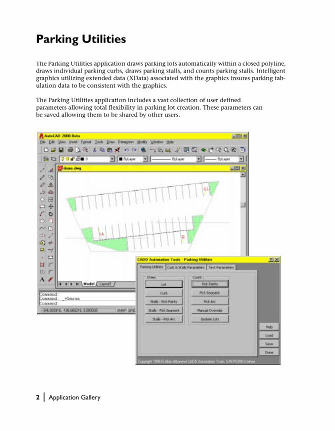
Parking Utilities
The Parking Utilities application draws parking lots automatically within a closed polyline, draws individual parking curbs, draws parking stalls, and counts parking stalls. Intelligent graphics utilizing extended data (XData) associated with the graphics insures parking tab-ulation data to be consistent with the graphics.
The Parking Utilities application includes a vast collection of user defined parameters allowing total flexibility in parking lot creation. These parameters can be saved allowing them to be shared by other users.
2 | Application Gallery

The Parking Utilities application is distributed as a stand-alone VBA project file. The application comes with an extensive help file.
The Parking Utilities application was developed by R. Allan Albanese of CADD Automation Tools. CADD Automation Tools is a company that specializes in developing applications for AutoCAD using Microsoft Visual Basic® for Applications.
You can find more information on this application and other CADD Automation applications at http://www.caddautomationtools.com.
Parking Utilities | 3

Map Coordinates to Spherical Coordinates
This application converts 2D latitudinal and longitudinal coordinates into 3D spherical coordinates. 3D polylines are then created from these new coordinates and displayed on a globe.
Using the AutoCAD 2000 3D orbit tool you can rotate the globe to be viewed from any position.
4 | Application Gallery

This application is distributed as a VBA project embedded in the Map2Globe.dwg drawing. The dialog box for this application has been designed to allow the user to change from the 2D map to the 3D globe quickly through the use of viewports.
The application was developed by Carlos Ramos, Applications Engineer for Autodesk Latin America.
The Map2Globe.dwg drawing can be found in the Sample\VBA directory of your installed AutoCAD 2000 product.
Map Coordinates to Spherical Coordinates | 5

Facility Database Link
This application links blocks in an AutoCAD drawing to records in a Microsoft Access da-tabase. Using this application users can edit records, create new records, remove records, and link objects in the drawing with records in the database. The code for this application was written in Visual Basic® and is distributed in the Facility.exe executable.
The database, code, exectuable, and drawing for this application can be found in the Sample\ActiveX\Facility directory of your installed AutoCAD 2000 product.
6 | Application Gallery

Facility Database Link | 7

Tower Calculations
The Power Transmission Tower Calculator application creates a transmission tower and performs a wide variety of calculations for the tower. The application uses a dialog box containing tabs to direct the user to the different stages of creation and analysis. All calculations are performed within the Visual Basic® code.
This application is distributed as a VBA project embedded in the Tower.dwg drawing. The Tower.dwg drawing can be found in the Sample\VBA directory of your installed AutoCAD 2000 product.
This application was developed by Carlos Ramos, Applications Engineer for Autodesk Latin America.
8 | Application Gallery

Tower Calculations | 9

Exporting Attribute Text
This application extracts the text for all the attributes in a drawing. The attribute data is sorted and placed into an Excel spreadsheet. The data is also mapped into a Microsoft Excel chart. Additionally, this application creates a Microsoft Word document containing a graph of the attribute data.
This application is distributed in a VBA project called attext.dvb and can be run with any drawing containing attributes. The attext.dvb project file can be found in the Sample\VBA directory of your installed AutoCAD 2000 product. This application was created by the Application Developer Framework team at Autodesk.
10 | Application Gallery

Exporting Attribute Text | 11

I-Beam Construction
The I-beam construction application creates an I-beam from parameters that the user defines in the dialog box. Once the I-beam has been created the user is free to adjust the design parameters. The I-beam object is dynamically updated as the user changes the design parameters.
12 | Application Gallery

This application is distributed as a stand-alone VBA project called ibeam3d.dvb. The project file can be found in the Sample\VBA directory of your installed AutoCAD 2000 product.
This application was created by Shashi Kant Rai of the Application Development Framework team at Autodesk.
I-Beam Construction | 13

14

In This Manual
Introduction
■ Overview of AutoCAD ActiveX Technology
■ Overview of AutoCAD Visual Basic for Applications (VBA) Interface
■ Examining the Strengths of AutoCAD ActiveX and VBA Together
■ How This Guide Is Organized
■ Conventions Used in This Guide
■ Finding Sample Code
This introduction describes the concept of exposing
AutoCAD objects through an ActiveX interface and
programming those objects using the Visual Basic for
Applications programming environment. Also included
is an introduction to all the documentation and sample
code provided for AutoCAD ActiveX and VBA.
15

Overview of AutoCAD ActiveX Technology
AutoCAD ActiveX provides a mechanism to manipulate AutoCAD program-matically from within or outside AutoCAD. It does this by exposing AutoCAD objects to the “outside world.” Once these objects are exposed, they can be accessed by many different programming languages and envi-ronments and by other applications such as Microsoft® Word VBA or Excel VBA.
There are two advantages to implementing an ActiveX interface for AutoCAD:
■ Programmatic access to AutoCAD drawings is opened up to many more programming environments. Before ActiveX Automation, developers were limited to an AutoLISP or C++ interface.
■ Sharing data with other Windows® applications, such as Microsoft Excel® and Word®, is made dramatically easier.
AutoCAD Application
drawing.dwg
AutoCAD ActiveX Objects
AutoCAD VBA
MS Word VBA
Visual Basic
Excel VBA
Delphi
C++
Java
16 | Introduction
Overview of AutoCAD ActiveX Objects
An object is the main building block of any ActiveX application. Each exposed object represents a precise part of AutoCAD. There are many differ-ent types of objects in the AutoCAD ActiveX interface. For example
■ Graphical objects such as lines, arcs, text, and dimensions are objects ■ Style settings such as linetypes and dimension styles are objects■ Organizational structures such as layers, groups, and blocks are objects■ The drawing displays such as view and viewport are objects■ Even the drawing and the AutoCAD application are considered objects
Overview of AutoCAD Visual Basic for Applications (VBA) Interface
Microsoft VBA is an object-oriented programming environment designed to provide rich development capabilities similar to those of Visual Basic (VB). The main difference between VBA and VB is that VBA runs in the same pro-cess space as AutoCAD, providing an AutoCAD-intelligent and very fast programming environment.
VBA also provides application integration with other VBA-enabled applica-tions. Which means AutoCAD, using other application object libraries, can be an Automation controller for other applications such as Microsoft Word or Excel.
The standalone development editions of Visual Basic, which must be pur-chased separately, complement AutoCAD VBA with additional components, such as an external database engine and report-writing capabilities.
There are four advantages to implementing VBA for AutoCAD:
■ The Visual Basic programming environment is easy to learn and use.■ VBA runs in-process with AutoCAD. This translates to very fast program
execution.■ Dialog construction is quick and effective. This allows developers to pro-
totype applications and quickly receive feedback on designs.■ Projects can be standalone or imbedded in drawings. This choice allows
developers great flexibility in the distribution of their applications.
Overview of AutoCAD Visual Basic for Applications (VBA) Interface | 17

How VBA Is Implemented in AutoCAD
VBA sends messages to AutoCAD by the AutoCAD ActiveX Automation inter-face. AutoCAD VBA permits the VBA environment to run simultaneously with AutoCAD and provides programmatic control of AutoCAD through the ActiveX Automation interface. This coupling of AutoCAD, ActiveX Automa-tion, and VBA provides an extremely powerful interface not only for manip-ulating AutoCAD objects, but for sending data to or retrieving data from other applications.
There are three fundamental elements that define ActiveX and VBA program-ming in AutoCAD. The first is AutoCAD itself, which has a rich set of objects that encapsulates AutoCAD entities, data, and commands. Because AutoCAD was designed as an open-architecture application with multiple levels of interface, familiarity with AutoCAD programmability is highly desirable in order to use VBA effectively. If you’ve used AutoLISP® to control AutoCAD programmatically, you already have a good understanding of the AutoCAD facilities. However, you will find the VBA object-based approach to be quite different from that of Visual LISP®.
The second element is the AutoCAD ActiveX Automation interface, which establishes messages (communication) with AutoCAD objects. Programming in VBA requires a fundamental understanding of ActiveX Automation. A description of the AutoCAD ActiveX Automation interface can be found in the ActiveX and VBA Reference. Even the experienced VB programmer will find the AutoCAD ActiveX Automation interface invaluable for understand-ing and developing AutoCAD VBA applications.
The third element is the VBA programming environment which has its own set of objects, keywords, constants, and so forth that provides program flow, control, debugging, and execution. Microsoft’s own extensive online help for VBA is included with the AutoCAD VBA and is accessible from the VBA IDE by any of the following methods:
■ Pressing F1 on the keyboard■ Choosing Help from the VBA IDE menus■ Clicking the Question Mark icon on the VBA IDE toolbar
18 | Introduction

Dependencies and Restrictions When Using AutoCAD VBA
To ensure the proper functionality of AutoCAD ActiveX and VBA you must comply with the following system dependencies:
Windows NT® 4.0
It is highly recommended that Service Pack 3 for Windows NT 4.0 be installed to run AutoCAD ActiveX and VBA.
Windows® 95, or Windows 98
No special requirements from Microsoft.
Installing, Reinstalling, or Uninstalling Microsoft Office or Other VBA Applications
If you install, reinstall, or uninstall Microsoft Office or other VBA applications after installing AutoCAD, you will need to reinstall AutoCAD. It is highly recommended that after any installation of AutoCAD you reboot your system.
Examining the Strengths of AutoCAD ActiveX and VBA Together
The AutoCAD ActiveX/VBA interface represents several advantages over other AutoCAD API environments:
■ Speed
Running in-process with VBA, ActiveX applications are faster than either AutoLISP or ADS applications.
■ Ease of Use
The programming language and development environment are easy to use and come installed with AutoCAD.
■ Windows Interoperability
ActiveX and VBA are designed to be used with other Windows applica-tions and provide an excellent path for communication of information across applications.
Examining the Strengths of AutoCAD ActiveX and VBA Together | 19

■ Rapid Prototyping
The rapid interface development of VBA provides the perfect environ-ment for prototyping applications, even if those applications will eventually be developed in another language.
■ Programmer Base
There are millions of Visual Basic programmers around the world. AutoCAD ActiveX and VBA technology open up AutoCAD customization and application development to these programmers and the many more who will learn Visual Basic in the future.
How This Guide Is Organized
This guide provides information regarding the development of ActiveX and VBA applications for use with AutoCAD 2000. Information specific to devel-oping applications using VBA can be found in chapter 1, “Getting Started with VBA,” and chapter 11, “Developing Applications with VBA.” Program-mers using ActiveX from a development environment other than VBA can skip these two chapters. However, be aware that all of the example code in this guide is presented in VBA.
A tutorial can be found in chapter 13, “Designing the Garden Path—An ActiveX/VBA Tutorial.” This tutorial walks a novice programmer through cre-ating a garden path in AutoCAD using ActiveX and VBA and is recom-mended for all users new to AutoCAD ActiveX and VBA.
Migration information can be found in appendix B, “Migrating from AutoCAD Release 14.01.” This information summarizes the changes to AutoCAD ActiveX and VBA since AutoCAD Release 14.01.
Conventions Used in This Guide
This guide assumes you have a working knowledge of the Visual Basic programming language, and does not attempt to duplicate or replace the abundance of documentation available on Visual Basic. If you need more information on the Visual Basic language or development environment usage, see the Visual Basic for Applications Help file developed by Microsoft, available from the Help menu in the interactive development environment (IDE).
20 | Introduction

Typographical Conventions
To orient you to AutoCAD features, specific terms are set in typefaces that dis-tinguish them from the body text. Throughout AutoCAD documentation, the following conventions are used.
Typographical conventions
Text element Example
AutoCAD commands
AutoCAD system variables
AutoCAD named objects, such as linetypes and styles
ADCENTER, DBCONNECT, SAVE
DIMBLK, DWGNAME, LWSCALE
DASHDOT, STANDARD
Prompts Select object to trim or [Project/Edge/Undo]:
Instructions after prompt sequences
File names
File name extensions
Folder or directory names
Select objects: Use an object selection method
acad2000.cfg, Readme file,
.dwg file name extension
Sample folder, c:\ACAD2000\support
Text you enter At the Command prompt, enter shape
Keys you press on the keyboard CTRL, F10, ESC, ENTER
Keys you press simultaneously on the keyboard CTRL + C
ActiveX argument names, constants, sample code, and VBA keywords
To create a new button as a flyout use the AddToolBarButton method and set the FlyoutButton argument to TRUE.circle.Color = acRed
AutoLISP variable names, sample code, and text in ASCII files
The variable pi is preset to a value of pi***POP1
AutoLISP and DIESEL function names command ads_command( )
AutoLISP Formal arguments specified in function definitions
The string and mode arguments
Conventions Used in This Guide | 21

Finding Sample Code
This manual and the ActiveX and VBA Reference together contain over 800 example VBA subroutines that demonstrate the usage of ActiveX methods, properties, and events.
There are also many sample applications provided in the /ACAD200/Sample directory with AutoCAD. These sample applications demonstrate a wide range of fuctionality, from extracting AutoCAD drawing data into Microsoft Excel spreadsheets to drawing and performing stress analysis on an electrical transmission tower. These samples will show you how to combine the versa-tility of the Visual Basic for Applications programming environment together with the power of AutoCAD ActiveX interface to create customized applications.
Running the Example Code in This Guide
All of the example code in the ActiveX and VBA Developer’s Guide and ActiveX and VBA Reference can be copied from the help files, pasted directly into the AutoCAD VBA environment, and then executed with one requirement: the current active drawing in AutoCAD must be a blank drawing open to model space. Additionally, the code in these manuals can be found in the SampleCode.dvb and Events.dvb files in the /ACAD200/Sample directory.
To run the examples
1 Copy the example from the help file into an empty VBA code module.
2 Verify that AutoCAD has a blank drawing open to model space.
3 Open the Macros dialog box by entering the command VBARUN.
4 Choose the macro and press Run.
More information on running macros and the Macros dialog box is available in “Running a Macro” on page 32.
Reviewing the Sample Applications
There are twenty-one sample applications provided in the /ACAD2000/Sample directory. This table provides the name, description, and location of the main source code file for each sample application. Many sample applications have support files that can be found in the same directory as the main source code file. There is also a readme.txt file in same
22 | Introduction
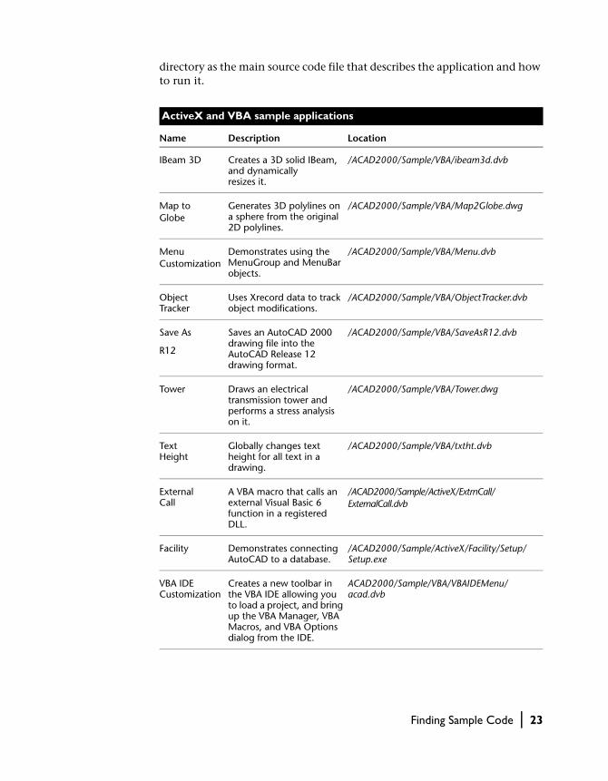
directory as the main source code file that describes the application and how to run it.
ActiveX and VBA sample applications
Name Description Location
IBeam 3D Creates a 3D solid IBeam, and dynamically resizes it.
/ACAD2000/Sample/VBA/ibeam3d.dvb
Map to Globe
Generates 3D polylines on a sphere from the original 2D polylines.
/ACAD2000/Sample/VBA/Map2Globe.dwg
Menu Customization
Demonstrates using the MenuGroup and MenuBar objects.
/ACAD2000/Sample/VBA/Menu.dvb
Object Tracker
Uses Xrecord data to track object modifications.
/ACAD2000/Sample/VBA/ObjectTracker.dvb
Save As
R12
Saves an AutoCAD 2000 drawing file into the AutoCAD Release 12 drawing format.
/ACAD2000/Sample/VBA/SaveAsR12.dvb
Tower Draws an electrical transmission tower and performs a stress analysis on it.
/ACAD2000/Sample/VBA/Tower.dwg
Text Height
Globally changes text height for all text in a drawing.
/ACAD2000/Sample/VBA/txtht.dvb
External Call
A VBA macro that calls an external Visual Basic 6 function in a registered DLL.
/ACAD2000/Sample/ActiveX/ExtrnCall/ExternalCall.dvb
Facility Demonstrates connecting AutoCAD to a database.
/ACAD2000/Sample/ActiveX/Facility/Setup/Setup.exe
VBA IDE Customization
Creates a new toolbar in the VBA IDE allowing you to load a project, and bring up the VBA Manager, VBA Macros, and VBA Options dialog from the IDE.
ACAD2000/Sample/VBA/VBAIDEMenu/acad.dvb
Finding Sample Code | 23

Extract Attributes
This Excel macro extracts AutoCAD block data and deposits the data in a spreadsheet.
ACAD2000/Sample/ActiveX/ExtAttr/ExtAttr.xls
Attribute Text
This AutoCAD macro extracts attribute data to Microsoft Word document, Excel spreadsheet, and Chart.
/ACAD2000/Sample/VBA/attext.dvb
Excel Link This AutoCAD macro demonstrates how to pass data from AutoCAD to Excel and then back to AutoCAD again.
/ACAD2000/Sample/VBA/ExcelLink.dvb
Block Replace
Replaces inserted blocks in drawing with a different block definition.
/ACAD2000/Sample/VBA/BlockReplace.dvb
Change Poly Width
Globally changes the widths of all polylines in the drawing.
/ACAD2000/Sample/VBA/chplywid.dvb
Draw Centerline
Draws centerlines for arcs, ellipses, and circles.
/ACAD2000/Sample/VBA/cntrline.dvb
Draw Line Demonstrates how to draw a line from a VBA form.
/ACAD2000/Sample/VBA/drawline.dvb
Example Code
All example code, except for the events examples, from the ActiveX and VBA Developer’s Guide and the ActiveX and VBA Reference.
/ACAD2000/Sample/VBA/Example_Code.dvb
Example Events
The events examples from the ActiveX and VBA Reference.
/ACAD2000/Sample/VBA/Example_Events.dvb
Miscellaneous Demonstrates various Automation APIs using a dialog interface.
/ACAD2000/Sample/VBA/acad_cg.dvb
ActiveX and VBA sample applications (continued)
Name Description Location
24 | Introduction

In This Chapter
Getting Started with VBA
1■ Understanding Embedded and
Global VBA Projects
■ Organizing Your Projects with the VBA Manager
■ Handling Your Macros
■ Editing Your Projects with the VBA IDE
■ Performing an Introductory Exercise
■ Getting More Information
■ Reviewing AutoCAD VBA Project Terms
■ Reviewing the AutoCAD VBA Commands
This chapter introduces you to AutoCAD VBA projects
and the VBA IDE. Although most VBA environments are
similar in behavior, the AutoCAD VBA IDE has some
unique features. There are also several AutoCAD com-
mands that can be used to load projects, run projects, or
open the VBA IDE. This chapter defines the use of VBA
projects, VBA commands, and the VBA IDE in general.
25

Understanding Embedded and Global VBA Projects
An AutoCAD VBA project is a collection of code modules, class modules, and forms that work together to perform a given function. Projects can be stored within an AutoCAD drawing, or as a separate file.
Embedded projects are stored within an AutoCAD drawing. These projects are automatically loaded whenever the drawing in which they are contained is opened in AutoCAD, making the distribution of projects very convenient. Embedded projects are limited and not able to open or close AutoCAD draw-ings because they function only within the document where they reside. Users of embedded projects are no longer required to find and load project files before they run a program. A time log that is triggered when the drawing is opened is an example of a project embedded in a drawing. With this macro users can log in and record the length of time they worked on the drawing. The user does not have to remember to load the project before opening the drawing; it simply is done automatically.
Global projects are stored in separate files and are more versatile because they can work in, open, and close any AutoCAD drawing, but are not automati-cally loaded when a drawing is opened. Users must know which project file contains the macro they need and then load that project file before they can run the macro. However, global projects are easier to share with other users, and they make excellent libraries for common macros. An example of a project you may store in a project file is a macro that collects a bill of mate-rials from many drawings. This macro can be run by an administrator at the end of a work cycle and can collect information from many drawings.
At any given time, users can have both embedded and global projects loaded into their AutoCAD session.
AutoCAD VBA projects are not binary compatible with standalone Visual Basic projects. However, the forms, modules, and classes can be exchanged between projects using the IMPORT and EXPORT VBA commands in the VBA IDE. For more information on the VBA IDE, see “Editing Your Projects with the VBA IDE” on page 34.
26 | Chapter 1 Getting Started with VBA

Organizing Your Projects with the VBA Manager
You can view all the VBA projects loaded in the current AutoCAD session by using the VBA Manager. It is an AutoCAD tool that allows you to load, unload, save, create, embed, and extract VBA projects.
To open the VBA Manager
1 From the Tools menu choose Macro ➤ VBA Manager.
2 Or, in AutoCAD invoke the VBAMAN command.
Loading an Existing Project
When you load a project into AutoCAD, all the public subroutines, also called macros, become available for use. Projects embedded in a drawing are loaded whenever the drawing is opened. Projects stored in DVB files must be loaded explicitly.
Organizing Your Projects with the VBA Manager | 27
To load an existing VBA project file
1 In the VBA Manager, use the Load option to bring up the Open VBA Project dialog box.
2 In the Open VBA Project dialog box, select the project file to open. The VBA Project dialog box will allow you to open only valid DVB files. If you attempt to open a different type of file, you will receive an error message.
3 Select Open.
You can also load a project file by using the VBALOAD command, which opens the Open VBA Project dialog box.
Additionally, anytime a project is loaded, any other projects that are refer-enced by the first project will be loaded automatically.
Additionally, AutoCAD will automatically load at startup any project file with the name acad.dvb.
Virus AlertEach time you load a project you are given the option of enabling or dis-abling the code within that project as a protection against viruses. If you enable the code, viruses in the code can begin executing. If you disable the code, the project will still be loaded, but all code within that project is pre-vented from running.
More information on the virus protection is available in “Setting the Project Options” on page 33.
Unloading a Project
Unloading a project frees up memory and keeps the list of loaded projects at a length that is easy to manage.
You cannot unload embedded projects or projects that are referenced by other loaded projects.
To unload a VBA project
1 In the VBA Manager, select the project you want to unload.
2 Choose Unload.
3 Or, use the VBAUNLOAD command, which prompts you for the project to be unloaded.
28 | Chapter 1 Getting Started with VBA

Embedding a Project into a Drawing
When you embed a project you place a copy of the project in the drawing database. The project is then loaded or unloaded whenever the drawing con-taining it is opened or closed.
A drawing can contain only one embedded project at a time. If a drawing already contains an embedded project you must extract it before a different project can be embedded into the drawing.
To embed a project in an AutoCAD drawing
1 Open the VBA Manager and select the project you want to embed.
2 Choose Embed.
Extracting a Project from a Drawing
When you extract a project you remove the project from the drawing data-base and are given the opportunity to save the project in an external project file. If you do not save the file in an external project file, the project data will be deleted.
To extract a project from an AutoCAD drawing
1 Open the VBA Manager and select the drawing from which the project is to be extracted.
2 Choose Extract.
3 If you want to save the project information in an external project file, choose Yes to the prompt “Do you want to export the VBA project before removing it?” The Save As dialog box will be displayed, allowing you to save the file.
If you do not want to save the project information in an external file, choose No to the prompt “Do you want to export the VBA project before removing it?” The project information will be removed from the drawing and will not be saved.
Organizing Your Projects with the VBA Manager | 29

Creating a New Project
New projects are created as unsaved global projects. Once a project has been created, you can then embed the project in a drawing, or save the project out to a project file.
To create a new VBA project
1 Open the VBA Manager.
2 Choose New.
A new project will be created with the default name of ACADProject. To change the project name you must go into the VBA IDE. For more informa-tion on naming your project in the VBA IDE, see “Naming Your Project” on page 39.
Saving Your Project
Embedded projects are saved whenever the drawing is saved. Global projects must be saved using the VBA Manager or the VBA IDE.
To save your project using the VBA Manager
1 Open the VBA Manager and select the project to be saved.
2 Choose Save As. The Save As dialog box will open.
3 Select the file name for the project to be saved in.
4 Choose Save.
30 | Chapter 1 Getting Started with VBA

Handling Your Macros
The Macros dialog box allows you to run, edit, delete, and create macros as well as set the VBA project options.
A macro is a public (executable) subroutine. Each project usually contains at least one macro.
To open the Macros dialog box
1 From the Tools menu choose Macro ➤ Macro.
2 Or, in AutoCAD invoke the VBARUN command.
The names of all macros in the valid range are displayed in this dialog box. You can change the valid range by using the Macros in: drop-down list. This list specifies the projects or drawings whose macros are displayed. You can choose to display the macros in
■ All drawings and projects■ All drawings■ All projects■ Any individual drawing currently open in AutoCAD■ Any individual project currently loaded in AutoCAD
By limiting the valid range you can control how many macro names appear in the list. This will help you in the cases when many macros are available in the loaded drawings and projects.
Handling Your Macros | 31

Running a Macro
Running a macro executes the macro code within the context of the current AutoCAD session. The current active drawing is considered to be the open drawing that has the focus when macro execution begins. All VBA references to the ThisDrawing object will refer to the current active drawing for macros in global projects. For macros in embedded projects, the ThisDrawing object always refers to the drawing in which the macro is embedded.
To run a macro
1 Open the Macros dialog box and select the macro to run.
2 Choose Run.
Editing a Macro
Editing a macro will open the VBA IDE with the chosen macro open in the Code window. For more information on editing macros in the VBA IDE see “Editing Your Projects with the VBA IDE” on page 34.
To edit a macro
1 Open the Macros dialog box and select the macro to edit.
2 Choose Edit.
Stepping into a Macro
Stepping into a macro begins execution of the macro and then halts the execution on the first line of code. The VBA IDE is opened with the chosen macro open in the Code window at the line of execution.
To step into a macro
1 In the Macros dialog box, select the macro to step into.
2 Choose Step.
Creating a New Macro
You can create a new empty macro.
32 | Chapter 1 Getting Started with VBA
To create a new macro
1 Open the Macros dialog box and enter the name for the new macro.
2 In the Macros in: drop-down list, select a project to create the new macro in.
3 Choose Create.
If a macro with the specified name already exists, you will be asked if you want to replace the existing macro.
If you select Yes at the prompt, the code in the existing macro will be deleted and a new, empty macro will be created with the specified name.
If you select No at the prompt, you will be returned to the Macros dialog box to enter a new name for the macro.
If you select Cancel at the prompt, the Macros dialog box will be dismissed and no new macro will be created.
Deleting a Macro
You can delete a macro from any project.
To delete a macro
1 Open the Macros dialog box and select the macro to delete.
2 Choose Delete. You will be prompted to confirm the delete.
3 At the prompt, choose Yes to delete the macro, or No to cancel the delete.
Setting the Project Options
There are three options that can be set for AutoCAD VBA projects:
■ Enabling auto embedding■ Allowing break on errors■ Enabling macro virus protection
To set the AutoCAD VBA project options
1 From the Tools menu choose Macro ➤ Macros to open the VBA Macros dia-log box.
2 From the VBA Macros dialog box, choose Options to open the Options dialog box.
3 From the Options dialog box, select the options you want to enable.
4 Choose OK.
Handling Your Macros | 33

Enabling Auto EmbeddingThe auto embed feature automatically creates an embedded VBA project for all drawings when the drawing is opened.
Allowing Break on ErrorsAllows VBA to enter Break mode when an error is encountered. Break mode is a temporary suspension of program execution in the interactive develop-ment environment. In Break mode, you can examine, debug, reset, step through, or continue program execution.
When this option is enabled, unhandled errors found during the execution of a VBA macro will suspend the execution of the macro and display the VBA IDE at the point of the error in the macro.
When this option is disabled, untrapped errors found during the execution of a VBA macro will display a message box alerting you to the error, and then end execution of the macro.
Enabling Macro Virus ProtectionThe virus protection mechanism displays a built-in warning message when-ever you open a drawing that may contain macro viruses.
Editing Your Projects with the VBA IDE
Once a project has been loaded into AutoCAD, you can edit the code, forms, and references for that project using the VBA interactive development envi-ronment. You can also debug and run projects from the VBA IDE.
Opening the VBA IDE
Once open, the VBA IDE provides access to all loaded projects.
To open the VBA IDE on demand
You can open the VBA IDE from the command line or from the menu bar.
■ From the command line, enter VBAIDE. ■ Or, from the Tools menu, use the Macro ➤ Visual Basic Editor.
34 | Chapter 1 Getting Started with VBA

To open the VBA IDE automatically on AutoCAD startup
If you want to open the VBA IDE automatically every time you start AutoCAD you will need to include the following line in the acad.rx file:
acadvba.arx
Viewing Project Information
The VBA IDE contains a window called the Project window, which displays a list of all loaded VBA projects. It also displays the code, class, and form mod-ules included in the project, the document associated with the project, all other VBA projects referenced from the project, and the physical location (path) of the project.
The Project window has its own toolbar, which can be used to open various project components for editing. Use the View Code button to open the code for a selected module. Use the View Object button to display selected objects such as forms.
The Project window is visible by default. If it is not visible, select Project win-dow from the View menu, or press CTRL+R.
Defining the Components in a Project
Each project can contain many different components. The different components a project can contain are objects, forms, standard modules, class modules, and references.
View Object
View Code
Editing Your Projects with the VBA IDE | 35

ObjectsThe object component represents the type of object, or document, that the VBA code will access. For AutoCAD VBA projects, this object represents the current AutoCAD drawing.
FormsThe form component contains the custom dialog boxes you constructed for use with your project.
Standard ModulesThe code module component contains your generic procedures and functions. A standard module is also referred to as a code module, or as sim-ply a module.
Class ModulesThe class module component contains all your own objects, which are defined as classes.
ReferencesThe reference component contains all your references to other projects or libraries.
Adding New ComponentsAdding new components creates a blank component in your project. You can add new modules, forms, and class modules to your project. You are respon-sible for updating all the properties of the component (such as the name of the component) and for filling in the appropriate code. When naming new components, remember that other developers may want to use your compo-nents in future applications. Follow the appropriate naming conventions for your development team.
To add a new component to your project
1 In the Project window of the VBA IDE, select the project to which you will be adding the component.
2 From the Insert menu, select UserForm, Module, or Class Module to add the new component to your project.
The new component will be added to your project and will appear in the Project window.
36 | Chapter 1 Getting Started with VBA
Importing Existing Components
Importing allows you to add an existing component to your project. You can import forms, modules, or class modules. Forms are imported as FRM files, modules are imported as BAS files, and class modules are imported as CLS files.
When you import a component file, a copy of the file you are importing is added to the project. The original file is left intact. Changes you make to the imported component do not alter the original component file.
If you import a component with the same name as an existing one, the file is added to your project with a number appended to it.
To import an existing component to your project
1 In the Project window of the VBA IDE, select the project to which you will be adding the component.
2 From the File menu, select Import File to open the Import File dialog box.
3 From the Import File dialog box, select the file to import and press Open.
The imported component will be added to your project and will appear in the Project window. To edit the properties of the component, select that compo-nent in the Project window. The properties for the selected component will be listed and can be edited in the Properties window.
Editing Components
You can edit standard modules, class modules, and forms in the VBA IDE. Standard and class modules are edited in a Code window. Forms are edited in the UserForm window using a special toolbox.
To edit a component in your project
1 In the Project window of the VBA IDE, select the component you want to edit.
2 Select the View Code button in the Project window to open a Code window.
3 Select the View Object button in the Project window to open a UserForm window and associated toolbox.
You can open as many Code windows as you have modules, so you can easily view the code in different forms or modules, and copy and paste between them.
Editing Your Projects with the VBA IDE | 37

To access the code associated with a form
■ Double-click on any control in the Form window. The code associated with that control will open in a Code window.
Using the Code WindowThe Code window contains two drop-down lists, a split bar, a margin indica-tor bar, and the full view and procedure view icons.
The two drop-down lists at the top of the Code window display the current object and procedure. You can move about your project by changing the object or procedure in these drop-down lists.
The split bar on the right side of the Code window allows you to split the window horizontally. Simply drag this bar down to create another window pane. This feature allows you to view two parts of code simultaneously in the same module. To close the pane, drag the split bar back to its original location.
The margin indicator bar is located down the left side of the Code window. It is used to display margin indicators that are used during code editing and debugging.
The full view and procedure view icons are located at the bottom-left corner of the Code window and toggle the display from only one procedure at a time to viewing the entire module at one time.
Using the UserForm WindowThe UserForm window allows you to create custom dialog boxes in your project.
To add a control simply drag the desired control from the toolbox and place it on the form. You can set your controls to align with the grid of your form from the General tab of the Options dialog box. You can view the form grid and determine the size of the gridlines from the General tab of the Options
split bar
current procedurecurrent object
marginindicatorbar
Procedure/FullView buttons
38 | Chapter 1 Getting Started with VBA

dialog box. (See “Setting the VBA IDE Options” on page 42 for more informa-tion on the Options dialog box.)
Each form you design will automatically have a Maximize, Minimize, and Close button. These buttons have already been implemented for you.
To add code to the control, simply double-click on the control once it has been placed on the form. This will open a Code window for the control.
Running Macros
In addition to running macros from the Macros dialog box, you can also run macros from the VBA IDE.
To run a macro from the VBA IDE
■ From the Run menu, use the Run Macro menu option.
If no macro or form is current, a dialog box will display allowing you to choose the macro to run.
If a given macro is current (the cursor is in a procedure), that macro will be executed.
Naming Your Project
The project name and the name of the .dvb file where the project is stored are two different values. You establish the name of the .dvb file the project is stored in when you save the project. The project name is set in the Properties window of the VBA IDE.
Editing Your Projects with the VBA IDE | 39

If you do not set the project name and file name, AutoCAD automatically assigns the following default names:
Project name: ACADProject
File name: Project.dvb
To change the name of a project
1 In the Project window of the VBA IDE, select the project to change.
2 In the Properties window, edit the Name property for the project.
To change the file name for a project
1 In the VBA IDE, select the Save option from the File menu.
2 In the Save As dialog box, enter the new name and location for the project file.
Saving Your Project
There is no explicit SAVE command in AutoCAD for VBA projects. Instead, the SAVE command resides in the File menu of the VBA IDE and in the VBA Manager. Any changes to a VBA project will access a standard Save VBA Project dialog box when one of these events occurs:
■ You pick the SAVE command from the VBA IDE■ You choose the Save As option in the VBA Manager■ Your AutoCAD session is about to end or quit and the VBA project is not
saved
40 | Chapter 1 Getting Started with VBA

NOTE Before you save a project, it is assigned the default file name project.dvb. It is important that you assign a new name to your project file when you save the project. If you save a project with the default file name project.dvb, you will no longer be able to create new empty projects. Each time you create a new project, you will actually be loading the saved project called project.dvb.
Referencing Other VBA Projects
Referencing one VBA project from another allows developers to share code more easily. Developers can create libraries of commonly used macros and then reference the library when needed. This keeps the shared code centrally located and supported, while allowing a large number of developers to utilize the code.
To reference another VBA project
1 In the Project window of the VBA IDE, select the project to which you will be adding the reference.
2 From the Tools menu, select the References option to open the References dialog box.
3 From the References dialog box, press the Browse button to open the Add Reference dialog box.
4 From the Add Reference dialog box, select the project file you want to refer-ence and then press the Open button.
5 From the Add Reference dialog box, select the OK button to complete the ref-erence addition.
Once another project has been successfully referenced, you will notice a new folder in the Projects window of the VBA IDE. This new folder is titled References and contains the name of the project referenced.
Once you have referenced a project, you can use any public code or form component in that project.
When a project that references another project is loaded into AutoCAD, the referenced project is automatically loaded into AutoCAD as well. The refer-enced project cannot be closed until all projects that reference it are closed first.
You cannot make circular references. That is, you cannot reference a project that contains a reference back to the first project. If you accidentally create a circular reference, you will be notified by VBA.
Editing Your Projects with the VBA IDE | 41

Project referencing is a standard feature of Microsoft VBA. There is no addi-tional work in AutoCAD to extend this functionality. You can find more information on referencing projects in the Microsoft Visual Basic help file. You can open the Microsoft Visual Basic help file from the Help menu in the VBA IDE.
NOTE You cannot reference embedded projects or VBA projects from other applications.
Setting the VBA IDE Options
You can change the characteristics of the VBA IDE using the Options dialog box. To open the Options dialog box, use the Tools menu and select Options.
The Options dialog box contains four tabs: Editor, Editor Format, General, and Docking.
EditorThe Editor tab specifies the Code window and Project window settings.
Code settings include
■ Auto Syntax Check■ Require Variable Declaration■ Auto List Member■ Auto Quick Info■ Auto Data Tips ■ Auto Indent ■ Tab Width
Window settings include
■ Drag and Drop Text Editing ■ Default to Full Module View ■ Procedure Separator Display
Editor FormatThe Editor Format tab specifies the appearance of your Visual Basic code.
You can
■ Change color of the code■ Change text list items■ Change foreground
42 | Chapter 1 Getting Started with VBA

■ Change background ■ Change margin indicators ■ Change text font and size ■ Display or hide the margin indicator■ Display or hide sample text for your settings
GeneralThe General tab specifies the settings, error handling, and compile settings for your current Visual Basic project.
You can
■ Change the grid settings for the form grid■ Display or hide tooltips ■ Set the automatic collapse of windows ■ Choose to receive state loss notifications ■ Determine how errors are handled■ Set the project to compile on demand or perform background
compilations
DockingThe Docking tab allows you to choose which windows you want to be dockable.
Performing an Introductory Exercise
Now that you have learned the basics of programming in AutoCAD VBA, let’s try creating a simple “Hello World” exercise. In this exercise you will create a new AutoCAD drawing, add a line of text to that drawing, then save the drawing, all from VBA.
Performing an Introductory Exercise | 43

Creating the "Hello World" text object
1 Open the VBA IDE by entering the following command from the AutoCAD command line:
Command: VBAIDE2 Open the Code window by selecting the Code option from the View menu
in the VBA IDE.
3 Create a new procedure in the project by selecting the Procedure option from the Insert menu in the VBA IDE.
4 When prompted for the procedure information, enter a name such as HelloWorld. Make sure the Type selected is Sub, and the Scope selected is Public.
5 Choose OK.
6 Enter the following code (that opens a new drawing) between the lines Public Sub HelloWorld() and End Sub.
ThisDrawing.Application.Documents.Add
7 Enter the following code (that creates the text string and defines its insertion location) immediately following the code entered in step 6.
Dim insPoint(0 To 2) As Double ’Declare insertion pointDim textHeight As Double ’Declare text heightDim textStr As String ’Declare text stringDim textObj As AcadText ’Declare text object
insPoint(0) = 2 ’Set insertion point x coordinateinsPoint(1) = 4 ’Set insertion point y coordinateinsPoint(2) = 0 ’Set insertion point z coordinate
textHeight = 1 ’Set text height to 1.0textStr = "Hello World!" ’Set the text string
’Create the Text objectSet textObj = ThisDrawing.ModelSpace.AddText _ (textStr, insPoint, textHeight)
8 Enter the code (that saves the drawing) immediately following the code entered in step 7.
ThisDrawing.SaveAs("Hello.dwg")
9 Run your program by selecting the Run Sub/UserForm option from the Run menu in the VBA IDE.
When the program finishes running, bring the AutoCAD application to the front. You should see your text “Hello World!” visible in your drawing. The drawing name should be Hello.dwg.
44 | Chapter 1 Getting Started with VBA
Getting More Information
More information on the VBA IDE and the Visual Basic programming lan-guage is available in the help files provided by Microsoft.
To access the Microsoft VBA IDE help files
■ From the Help menu in the VBA IDE, select Microsoft Visual Basic Help.
Reviewing AutoCAD VBA Project Terms
Global Project
A VBA project stored in a .dvb file.
Embedded Project
A VBA project stored in an AutoCAD drawing.
Regular Document
An AutoCAD drawing that does not contain VBA embedded projects.
Smart Document
An AutoCAD drawing that contains one or more VBA embedded projects.
Current Project
The project currently selected in the VBA IDE.
ThisDrawing
ThisDrawing is a VBA programming term used to represent the current drawing. For global projects, ThisDrawing always refers to the active document in AutoCAD. For embedded projects, ThisDrawing always refers to the document containing the project.
VBA IDE
The VBA interactive development environment. This application allows you to edit the code and forms in your project, or copy code and forms from other projects. It also allows you to set references to other application Object Models.
Getting More Information | 45

VBA Manager
The VBA Manager allows you to manage your projects. You can create, delete, embed, or extract projects. You can also view which projects, if any, are embedded in an open drawing.
Macros Dialog Box
The Macros dialog box allows you to run, delete, and create new macros, and provides access to the VBA project options.
Reviewing the AutoCAD VBA Commands
VBAIDE Brings up the VBA IDE.
The VBA IDE allows you to edit, run, and debug programs interactively. Although the VBA IDE is invoked only when AutoCAD is running, it can be minimized, opened, and closed independent of the AutoCAD Application window.
VBALOAD Loads a VBA project into the current AutoCAD session.
VBARUN Runs a VBA macro from the Macros dialog box or from the AutoCAD command line.
VBAUNLOAD Unloads a VBA project from the current AutoCAD session.
If the VBA project is modified but not saved, the user is asked to save it with the Save Project dialog box (or command line equivalent).
VBAMAN Displays the VBA Manager allowing you to view, create, load, close, embed, and extract projects.
VBASTMT Executes a VBA statement from the AutoCAD command line.
46 | Chapter 1 Getting Started with VBA
In This Chapter
Understanding ActiveX Automation Basics
2■ Understanding the AutoCAD
Object Model
■ Accessing the Object Hierarchy
■ Working with the Collection Objects
■ Understanding Properties and Methods
■ Understanding Parent Objects
■ Locating the Type Library
■ Retrieving the First Entity in the Database
■ Using Variants in Methods and Properties
■ Using Other Programming Languages
To use AutoCAD ActiveX Automation effectively you
should be familiar with the AutoCAD entities, objects,
and features relating to the type of application you are
developing. The greater your knowledge of an object’s
graphical and nongraphical properties, the easier it is for
you to manipulate them through AutoCAD ActiveX
Automation.
Remember that the AutoCAD ActiveX Automation Help
file is available—just press F1. If you are having trouble
with a particular object, method, or property, highlight
the object, method, or property in the VBA IDE and
press F1.
47

Understanding the AutoCAD Object Model
An object is the main building block of the AutoCAD ActiveX interface. Each exposed object represents a precise part of AutoCAD. There are many differ-ent types of objects in the AutoCAD ActiveX interface. For example
■ Graphical objects such as lines, arcs, text, and dimensions are objects■ Style settings such as linetypes and dimension styles are objects■ Organizational structures such as layers, groups, and blocks are objects■ The drawing display such as view and viewport are objects■ Even the drawing and the AutoCAD application are considered objects
The objects are structured in a hierarchical fashion, with the Application object at the root. The view of this hierarchical structure is referred to as the Object Model. The Object Model shows you which object provides access to the next level of objects.
48 | Chapter 2 Understanding ActiveX Automation Basics
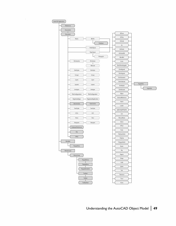
.
AutoCAD Application
Preferences
Documents
MenuBar
Blocks
Dictionaries
Blo9ck
ModelSpace
PaperSpace
Document
Database
Dictionary
DimStyles DimStyle
Groups Group
Layers Layer
Layouts Layout
Linetypes Linetype
PlotConfigurations PlotConfiguration
RegisteredApps RegisteredApplication
SelectionSets SelectionSet
TextStyles TextStyle
UCSs UCS
Views View
Viewports
PopupMenu
PopupMenus
PopupMenu
PopupMenuItem
ToolbarItem
Toolbars
Toolbar
MenuGroups
MenuGroup
Hyperlinks
Hyperlink
DatabasePreferences
Plot
Utility
Viewport
XRecord
3DFace
3DSolid
Arc
Attribute
AttributeRef
BlockRef
Circle
Dim3PointAngular
DimAligned
DimAngular
DimDiametric
DimOrdinate
DimRadial
3DPoly
Ellipse
ExternalReference
Hatch
Leader
LightweightPolyline
Line
MInsertBlock
MLine
MText
Point
PolyfaceMesh
Polyline
PolygonMesh
Raster
Ray
Region
Shape
Solid
Spline
Text
Tolerance
Trace
XLine
DimRotated
PViewport
Understanding the AutoCAD Object Model | 49

A Brief Look at the Application Object
The Application object is the Root object for the AutoCAD ActiveX Automation Object Model. From the Application object, you can access any of the other objects, or the properties or methods assigned to any object.
For example, the Application object has a Preferences property that returns the Preferences object. This object provides access to the registry-stored set-tings in the Options dialog box. (Drawing-stored settings are contained in the DatabasePreferences object, which will be discussed later.) Other proper-ties of the Application object give you access to application-specific data such as the application name and version, and the AutoCAD size, location, and visibility. The methods of the Application object perform application-specific actions such as listing, loading, and unloading ADS and ARX applications, and quitting AutoCAD.
The Application object also provides links to the AutoCAD drawings through the Documents collection, the AutoCAD menus and toolbars through the MenuBar and MenuGroups collections, and the VBA IDE through a property called VBE.
The application object is also the Global object for the ActiveX interface. This means that all the methods and properties for the Application object are available in the global name space.
A Brief Look at the Document Object
The Document object, which is actually an AutoCAD drawing, is found in the Documents collection and provides access to all of the graphical and most of the nongraphical AutoCAD objects. Access to the graphical objects (lines, circles, arcs, and so forth) is provided through the ModelSpace and PaperSpace collections, and access to nongraphical objects (layers, linetypes, text styles, and so forth) is provided through like-named collections such as
AutoCAD Application
Preferences
Documents
MenuBar
MenuGroups
50 | Chapter 2 Understanding ActiveX Automation Basics
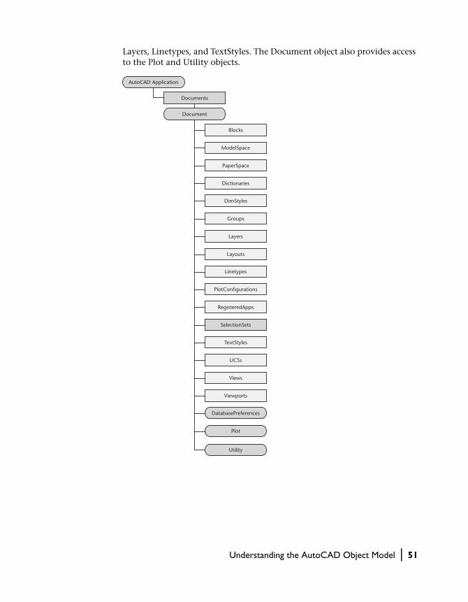
Layers, Linetypes, and TextStyles. The Document object also provides access to the Plot and Utility objects.
AutoCAD Application
Document
DatabasePreferences
Plot
Utility
Documents
Blocks
ModelSpace
PaperSpace
Dictionaries
DimStyles
Groups
Layers
Layouts
Linetypes
PlotConfigurations
RegisteredApps
SelectionSets
TextStyles
UCSs
Views
Viewports
Understanding the AutoCAD Object Model | 51

A Brief Look at the Collection Objects
AutoCAD groups most objects in collections. Although these collections con-tain different types of data, they can be processed using similar techniques. Each collection has a method for adding an object to the collection. Most col-lections use the Add method for this purpose. However, entity objects are usually added using a method titled Add<Entityname>. For example, to add a line you would use the AddLine method.
Collections also have some other methods and properties in common. The Count property can be used to obtain a zero-based count of the objects in a collection. The Item method can be used to obtain any object within a collection.
A Brief Look at the Graphical and Nongraphical Objects
Graphical objects, also known as entities, are the visible objects (lines, circles, raster images, and so forth) that make up a drawing. To create these objects, use the appropriate Add<Entityname> method. To modify or query these objects, use the methods or properties of the object itself. Each graphical object has methods that allow an application to perform most of the AutoCAD editing commands such as Copy, Erase, Move, Mirror, and so forth. These objects also have methods for setting and retrieving extended data (xdata), highlighting and updating, and retrieving the bounding box of the object. Graphical objects have typical properties such as Layer, Linetype, Color, and Handle. They also have specific properties, depending on their object type, such as Center, Radius, and Area.
Nongraphical objects are the invisible (informational) objects that are part of a drawing, such as Layers, Linetypes, DimStyles, SelectionSets, and so forth. To create these objects, use the Add method of the parent Collection object. To modify or query these objects, use the methods or properties of the object itself. Each nongraphical object has methods and properties specific to its purpose; all have methods for setting and retrieving extended data (xdata), and deleting themselves.
A Brief Look at the Preferences, Plot, and Utility Objects
Under the Preferences object is a set of objects, each corresponding to a tab in the Options dialog box. Together, these objects provide access to all the registry-stored settings in the Options dialog box. Drawing-stored settings
52 | Chapter 2 Understanding ActiveX Automation Basics

are contained in the DatabasePreferences object. You can also set and modify options (and system variables that are not part of the Options dialog box) with the SetVariable and GetVariable methods. For more information on set-ting options see “Setting AutoCAD Preferences” on page 69.
The Plot object provides access to settings in the Plot dialog box and gives an application the ability to plot the drawing using various methods. For more information on plotting, see “Plotting Your Drawing” on page 288.
The Utility object provides user input and conversion functions. The user input functions are methods that prompt the user on the AutoCAD com-mand line for input of various types of data, such as strings, integers, reals, points, and so forth. The conversion functions are methods that operate on AutoCAD-specific data types such as points and angles, in addition to string and number handling. For more information on the user input functions, see “Prompting for User Input” on page 94.
AutoCAD Application
Document
Preferences
DatabasePreferences
Plot
Utility
PreferencesDisplay
PreferencesDrafting
PreferencesFiles
PreferencesOpenSave
PreferencesOutput
PreferencesProfile
PreferencesSelection
PreferencesSystem
PreferencesUser
Documents
Understanding the AutoCAD Object Model | 53

Accessing the Object Hierarchy
Accessing the object hierarchy is easy from within VBA. This is because VBA is running in-process with the current AutoCAD session so there is no addi-tional step needed to connect it to the application.
VBA provides a link to the active drawing in the current AutoCAD session through the ThisDrawing object. By using ThisDrawing you gain immediate access to the current Document object and all of its methods and properties, and all of the other objects in the hierarchy.
When used in global projects, ThisDrawing always refers to the active docu-ment in AutoCAD. When used in embedded projects, ThisDrawing always refers to the document containing the project. For example, the following line of code in a global project saves whatever drawing is currently active in AutoCAD:
ThisDrawing.Save
Referencing Objects in the Object HierarchyYou can reference objects directly or through a user-defined variable. To ref-erence the objects directly, include the object in the calling hierarchy. For example, the following statement adds a line to the model space. Notice that the hierarchy starts with ThisDrawing, goes to the ModelSpace object, and then calls the AddLine method:
Dim startPoint(0 To 2) As Double, endPoint(0 To 2) As DoubleDim LineObj as AcadLinestartPoint(0) = 0: startPoint(1) = 0: startPoint(2) = 0endPoint(0) = 30: endPoint(1) = 20: endPoint(2) = 0Set LineObj = ThisDrawing.ModelSpace.AddLine(startPoint,endPoint)
To reference the objects through a user-defined variable, define the variable as desired type, then set the variable to the appropriate object. For example, the following code defines a variable (moSpace) of type AcadModelSpace and sets the variable equal to the current model space:
Dim moSpace As AcadModelSpaceSet moSpace = ThisDrawing.ModelSpace
The following statement then adds a line to the model space using the user-defined variable:
Dim startPoint(0 To 2) As Double, endPoint(0 To 2) As DoubleDim LineObj as AcadLinestartPoint(0) = 0: startPoint(1) = 0: startPoint(2) = 0endPoint(0) = 30: endPoint(1) = 20: endPoint(2) = 0Set LineObj = moSpace.AddLine(startPoint,endPoint)
54 | Chapter 2 Understanding ActiveX Automation Basics

Accessing the Application ObjectBecause the ThisDrawing object provides a link to the Document object, you may be wondering how you access the root object (Application object), which is situated above the Document object in the object hierarchy. The Document object has a property called Application that provides a link to the Application object.
For example, the following line of code updates the application:
ThisDrawing.Application.Update
Working with the Collection Objects
A Collection object is a predefined object that contains (is a parent object for) all instances of a similar object. There is a Collection object for the following objects:
Documents Collection
Contains all documents open in the current AutoCAD session.
ModelSpace Collection
Contains all graphical objects (entities) in model space.
PaperSpace Collection
Contains all graphical objects (entities) in the active paper space layout.
Block Object
Contains all entities within a specific block definition.
Blocks Collection
Contains all blocks in the drawing.
Dictionaries Collection
Contains all dictionaries in the drawing.
DimStyles Collection
Contains all dimension styles in the drawing.
Groups Collection
Contains all groups in the drawing.
Working with the Collection Objects | 55
Hyperlinks Collection
Contains all hyperlinks for a given entity.
Layers Collection
Contains all layers in the drawing.
Layouts Collection
Contains all layouts in the drawing.
Linetypes Collection
Contains all linetypes in the drawing.
MenuBar Collection
Contains all menus currently displayed in AutoCAD.
MenuGroups Collection
Contains all menus and toolbars currently loaded in AutoCAD.
RegisteredApplications Collection
Contains all registered applications in the drawing.
SelectionSets Collection
Contains all selection sets in the drawing.
TextStyles Collection
Contains all text styles in the drawing.
UCSs Collection
Contains all user coordinates systems (UCS) in the drawing.
Views Collection
Contains all views in the drawing.
Viewports Collection
Contains all viewports in the drawing.
Accessing a Collection
Most collection objects are accessed through the Document object. The Document object contains a property for each of the Collection objects. For
56 | Chapter 2 Understanding ActiveX Automation Basics

example, the following code defines a variable and sets it to the Layers col-lection of the current drawing:
Dim layerCollection as AcadLayersSet layerCollection = ThisDrawing.Layers
The Documents collection, MenuBar collection, and MenuGroups collection are accessed through the Application object. The Application object contains a property for each of these collections. For example, the following code defines a variable and sets it to the MenuGroups collection for the application:
Dim MenuGroupsCollection as AcadMenuGroupsSet MenuGroupsCollection = ThisDrawing.Application.MenuGroups
Adding a New Member to a Collection Object
To add a new member to the collection, use the Add method. For example, the following code creates a new layer and adds it to the Layers collection:
Dim newLayer as AcadLayerSet newLayer = ThisDrawing.Layers.Add("MyNewLayer")
Iterating through a Collection Object
To select a specific member of a Collection object, use the Item method. The Item method requires an identifier as either an index number specifying the location of the item within the collection or a string representing the name of the item.
The following example iterates through a collection and displays the names of all layers in the collection:
Iterating through the Layers collection
Sub Ch2_IterateLayer() ’ Iterate through the collection On Error Resume Next Dim I As Integer Dim msg As String msg = "" For I = 0 To ThisDrawing.Layers.count - 1 msg = msg + ThisDrawing.Layers.Item(I).Name + vbCrLf Next MsgBox msgEnd Sub
Working with the Collection Objects | 57

The following example uses the Item method to find a layer named “ABC”:
Finding the layer named “ABC”
Sub Ch2_FindLayerABC() ’ Use the Item method to find a layer named "ABC" On Error Resume Next
Dim ABCLayer As AcadLayer Set ABCLayer = ThisDrawing.Layers.Item("ABC") If Err <> 0 Then MsgBox "The layer ’ABC’ does not exist." End IfEnd Sub
NOTE Do not use the entity edit methods (Copy, Array, Mirror, and so forth) on any object while simultaneously iterating through a collection using the For Each mechanism. Either finish your iteration before you attempt to edit an object in the collection or create a temporary array and set it equal to the collection. Then you can iterate through the copied array and perform your edits.
Deleting a Member of a Collection Object
To delete a specific dimension style, use the Delete method found on the member object. For example, the following code deletes the layer ABC:
Dim ABCLayer as AcadLayerSet ABCLayer = ThisDrawing.Layers.Item("ABC")ABCLayer.Delete
Once an object has been deleted, you must never attempt to access the object again later in the program.
Understanding Properties and Methods
Each object has associated properties and methods. Properties describe aspects of the individual object, while methods are actions that can be per-formed on the individual object. Once an object is created, you can query and edit the object through its properties and methods.
For example, a Circle object has the Center property. This property represents the 3D World Coordinate System coordinate at the center of that circle. To change the center of the circle, simply set this property to the new coordi-nate. The Circle object also has a method called Offset. This method creates
58 | Chapter 2 Understanding ActiveX Automation Basics

a new object at a specified offset distance from the existing circle. To see a list of all properties and methods for the Circle object, refer to the Circle object in the AutoCAD ActiveX and VBA Reference.
Understanding Parent Objects
Each object has a parent object to which it is permanently linked. All objects originate from a single parent object called the root object. You can access all the objects in the interface by following the links from the root to the child objects. Additionally, all objects have a property called Application that links directly back to the root object.
The root object for the AutoCAD interface is the AutoCAD application.
Locating the Type Library
The objects, properties, and methods exposed by automation objects are con-tained in a type library. A type library is a file or part of a file that describes the type of one or more objects. Type libraries do not store objects; they store information. By accessing a type library, applications and browsers can deter-mine the characteristics of an object, such as the interfaces supported by the object and the names and addresses of the members of each interface.
Before you can use the automation object exposed by an application, you must reference its type library. The reference is automatically set in AutoCAD VBA. For other interactive development environments you must create the reference.
You can use an application’s objects without referencing the application’s type library. However, it is preferable to add the type library reference for the following reasons:
■ Globally accessible functions may be accessed directly without qualification.
■ Invocation of functions, properties, and methods can be checked at compile time for correctness, and therefore will execute more quickly at runtime.
■ It is possible to declare variables of the types defined in the library, which increases run-time reliability and readability.
Understanding Parent Objects | 59
Retrieving the First Entity in the Database
The following example returns the first entity object in model space. Similar code can do the same for paper space entities:
Retrieving the first entity in model space
Sub Ch2_FindFirstEntity() ’ This example returns the first entity in model space On Error Resume Next Dim entity As AcadEntity If ThisDrawing.ModelSpace.count <> 0 Then Set entity = ThisDrawing.ModelSpace.Item(0) MsgBox entity.ObjectName + _ " is the first entity in model space." Else MsgBox "There are no objects in model space." End IfEnd Sub
Using Variants in Methods and Properties
AutoCAD ActiveX Automation uses variants to pass arrays of data. Although this may seem confusing to a novice user, it is not difficult once you learn the basics. In addition, AutoCAD ActiveX Automation provides utilities to help you convert your data types.
What Is a Variant?
A variant is a special data type that can contain any kind of data except fixed-length string data and user-defined types. A variant can also contain the special values Empty, Error, Nothing, and NULL. You can determine how the data in a variant is treated using the VarType or TypeName Visual Basic functions.
You can use the Variant data type in place of most any data type to work with data in a more flexible way.
60 | Chapter 2 Understanding ActiveX Automation Basics

Using Variants for Array Data
Variants are used to pass array data in and out of AutoCAD ActiveX Automa-tion. This means that your arrays must be a variant to be accepted by AutoCAD ActiveX Automation methods and properties. In addition, array data output from AutoCAD ActiveX Automation must be handled as a variant.
NOTE In AutoCAD, VBA input arrays are automatically converted to variants. This means that you don’t have to provide a variant array as input to the ActiveX Automation methods and properties when using them from VBA. However, all the output arrays will be in the form of variants, so remember to handle them appropriately.
Converting Arrays to Variants
AutoCAD ActiveX Automation provides a utility method to convert an array of data into a variant. This method is the CreateTypedArray method, which creates a variant that contains an array of integers, floating numbers, dou-bles, and so forth. You can pass the resulting variant into any AutoCAD method or property that accepts an array of numbers as a variant.
The CreateTypedArray method takes as input the type of values that are in the array, and the array of data to be converted. It returns the array of values as a variant. The following code converts three arrays using CreateTypedAr-ray: the coordinates for a spline’s fit points, and the start and end tangent of the spline. It then passes the variant into the AddSpline method to create the spline.
Using Variants in Methods and Properties | 61

Creating a spline using the CreateTypedArray method
Sub Ch2_CreateSplineUsingTypedArray() ’ This example creates a spline object in model space ’ using the CreateTypedArray method. Dim splineObj As AcadSpline Dim startTan As Variant Dim endTan As Variant Dim fitPoints As Variant Dim noOfPoints As Integer Dim utilObj As Object ’ late bind the Utility object Set utilObj = ThisDrawing.Utility ’ Define the Spline Object utilObj.CreateTypedArray _ startTan, vbDouble, 0.5, 0.5, 0 utilObj.CreateTypedArray _ endTan, vbDouble, 0.5, 0.5, 0 utilObj.CreateTypedArray _ fitPoints, vbDouble, 0, 0, 0, 5, 5, 0, 10, 0, 0 noOfPoints = 3 Set splineObj = ThisDrawing.ModelSpace.AddSpline _ (fitPoints, startTan, endTan) ’ Zoom in on the newly created spline ZoomAll End Sub
Interpreting Variant Arrays
Array information passed back from AutoCAD ActiveX Automation is passed back as a variant. If you know the data type of the array, you can simply access the variant as an array. If you don’t know the data type contained in the variant, use the VBA functions VarType or Typename. These functions return the type of data in the variant. If you need to iterate through the array, you can use the VBA For Each statement.
The following code demonstrates calculating the distance between two points input by the user. In this example, the data type is known because all coordinates are doubles. 3D coordinates are a three-element array of doubles and 2D coordinates are a two-element array of doubles.
62 | Chapter 2 Understanding ActiveX Automation Basics

Calculating the distance between two points
Sub Ch2_CalculateDistance() Dim point1 As Variant Dim point2 As Variant ’ Get the points from the user point1 = ThisDrawing.Utility.GetPoint _ (, vbCrLf & "First point: ") point2 = ThisDrawing.Utility.GetPoint _ (point1, vbCrLf & "Second point: ") ’ Calculate the distance between point1 and point2 Dim x As Double, y As Double, z As Double Dim dist As Double x = point1(0) - point2(0) y = point1(1) - point2(1) z = point1(2) - point2(2) dist = Sqr((Sqr((x ^ 2) + (y ^ 2)) ^ 2) + (z ^ 2)) ’Display the resulting distance MsgBox "The distance between the points is: " _ & dist, , "Calculate Distance"End Sub
Using Other Programming Languages
This manual and the AutoCAD ActiveX and VBA Reference are written for the VBA programming language. The programming examples and sample appli-cations are written in VBA. To use the code in other programming environ-ments, you must update it for the chosen environment.
Use the documentation for your development environment to help you con-vert the example code.
Converting the VBA Code to VB
To update the coding examples for use with VB, you must first reference the AutoCAD type library. To do this in VB, select the References option from the Project menu to launch the Reference dialog box. From the References dialog box, choose AutoCAD 2000 Type Library and press OK.
Next, in the code example replace all references to ThisDrawing with a user-specified variable referencing the active document. To do this, define a variable for the AutoCAD application (myApp) and for the current document (myDoc). Then, set the application variable to the current AutoCAD application.
Using Other Programming Languages | 63

If AutoCAD is running, the GetObject method retrieves the AutoCAD Appli-cation object. If AutoCAD is not running, an error occurs that (in this example) is trapped, then cleared. The CreateObject method then attempts to create an AutoCAD Application object. If it succeeds, AutoCAD is started; if it fails, a message box displays a description of the error. The following code example uses the Clear and Description properties of Err. If your coding envi-ronment does not support these properties, you will need to modify the example appropriately:
Connecting to AutoCAD from Visual Basic
Sub Ch2_ConnectToAcad() Dim acadApp As AcadApplication On Error Resume Next Set acadApp = GetObject(, "AutoCAD.Application") If Err Then Err.Clear Set acadApp = CreateObject("AutoCAD.Application") If Err Then MsgBox Err.Description Exit Sub End If End If MsgBox "Now running " + acadApp.Name + _ " version " + acadApp.VersionEnd Sub
Next, set the document variable to the Document object in the AutoCAD application. The Document object is returned by the ActiveDocument prop-erty of the Application object.
Dim acadDoc as AcadDocumentSet acadDoc = acadApp.ActiveDocument
From this point on, use the acadDoc variable to reference the current AutoCAD drawing.
NOTE When running multiple sessions of AutoCAD, the GetObject function will return the first instance of AutoCAD in the Windows Running Object Table. See the Microsoft Visual Basic documentation on the Running Object Table (ROT) and the GetObject function for more information on verifying the session returned by GetObject.
64 | Chapter 2 Understanding ActiveX Automation Basics

VBA versus VB Comparison Code ExampleThe following code example demonstrates creating a line in both VBA and VB:
Creating a line using VBA
Sub Ch2_AddLineVBA() ’ This example adds a line ’ in model space Dim lineObj As AcadLine Dim startPoint(0 To 2) As Double Dim endPoint(0 To 2) As Double ’ Define the start and end ’ points for the line startPoint(0) = 1 startPoint(1) = 1 startPoint(2) = 0 endPoint(0) = 5 endPoint(1) = 5 endPoint(2) = 0 ’ Create the line in model space Set lineObj = ThisDrawing. _ ModelSpace.AddLine _ (startPoint, endPoint) ’ Zoom in on the newly created line ZoomAllEnd Sub
Creating a line using VB
Sub Ch2_AddLineVB() On Error Resume Next ’ Connect to the AutoCAD application Dim acadApp As AcadApplication Set acadApp = GetObject _ (, "AutoCAD.Application") If Err Then Err.Clear Set acadApp = CreateObject _ ("AutoCAD.Application") If Err Then MsgBox Err.Description Exit Sub End If End If ’ Connect to the AutoCAD drawing Dim acadDoc As AcadDocument Set acadDoc = acadApp.ActiveDocument
Using Other Programming Languages | 65

’ Establish the endpoints of the line Dim lineObj As AcadLine Dim startPoint(0 To 2) As Double Dim endPoint(0 To 2) As Double startPoint(0) = 1 startPoint(1) = 1 startPoint(2) = 0 endPoint(0) = 5 endPoint(1) = 5 endPoint(2) = 0 ’ Create a Line object in model space Set lineObj = acadDoc.ModelSpace.AddLine _ (startPoint, endPoint) ZoomAllEnd Sub
66 | Chapter 2 Understanding ActiveX Automation Basics

In This Chapter
Controlling the AutoCAD Environment
3■ Opening, Saving, and Closing
Drawings
■ Setting AutoCAD Preferences
■ Controlling the Application Window
■ Controlling the Drawing Windows
■ Resetting Active Objects
■ Setting and Returning System Variables
■ Drawing with Precision
■ Prompting for User Input
■ Accessing the AutoCAD Command Line
■ Working with No Documents Open
■ Importing Other File Formats
■ Exporting to Other File Formats
This chapter describes the fundamentals you need to
know when developing an application in AutoCAD. It
explains how to control the AutoCAD environment and
how to work effectively in that environment.
67

Opening, Saving, and Closing Drawings
The Documents collection and Document object provide access to the AutoCAD file functions.
To create a new drawing, or open an existing drawing, use the methods on the Documents collection. The Add method creates a new drawing and adds that drawing to the Documents collection. The Open method opens an exist-ing drawing. There is also a Close method on the Documents collection that closes all the drawings open in the AutoCAD session.
To save, import, or export a drawing, use the Save, SaveAs, Import, and Export methods on the Document object.
Opening a drawing
This example uses the Open method to open an existing drawing. The Visual Basic Dir function is used to check for the existence of the file before trying to open it. You should change the drawing file name or path to specify an existing AutoCAD drawing file on your system.
Sub Ch3_OpenDrawing() Dim dwgName As String dwgName = "c:\Program Files\acad2000\sample\campus.dwg" If Dir(dwgName) <> "" Then ThisDrawing.Application.Documents.Open dwgName Else MsgBox "File " & dwgName & " does not exist." End IfEnd Sub
Creating a new drawing
This example uses the Add method to create a new drawing based on the default template.
Sub Ch3_NewDrawing() Dim docObj As AcadDocument Set docObj = ThisDrawing.Application.Documents.AddEnd Sub
Saving a Drawing
Use either the Save or SaveAs methods to save a drawing.
Saving the active drawing
The following example saves the active drawing under its current name and again under a new name.
68 | Chapter 3 Controlling the AutoCAD Environment

Sub Ch3_SaveActiveDrawing() ’ Save the active drawing under the current name ThisDrawing.Save ’ Save the active drawing under a new name ThisDrawing.SaveAs "MyDrawing.dwg"End Sub
Occasionally you will want to check if the active drawing has any unsaved changes in it. It is a good idea to do this before you quit the AutoCAD session or start a new drawing. Use the Saved property to make sure that the current drawing does not contain any unsaved changes.
Testing if a drawing has unsaved changes
This example checks to see if there are unsaved changes and verifies with the user that it is OK to save the drawing (if it is not OK, skip to the end). If OK, use the Save method to save the current drawing, as shown here:
Sub Ch3_TestIfSaved() If Not (ThisDrawing.Saved) Then If MsgBox("Do you wish to save this drawing?", _ vbYesNo) = vbYes Then ThisDrawing.Save End If End IfEnd Sub
Setting AutoCAD Preferences
There are nine objects pertaining to options, each representing a tab on the Options dialog box. These objects provide access to all of the registry-stored options in the Options dialog box. You can customize many of the AutoCAD settings by using properties found on these objects. These objects are
■ PreferencesDisplay■ PreferencesDrafting■ PreferencesFiles■ PreferencesOpenSave■ PreferencesOutput■ PreferencesProfile■ PreferencesSelection■ PreferencesSystem■ PreferencesUser
Setting AutoCAD Preferences | 69

These objects are accessible via the Preferences object. To gain access to the Preferences object, use the Preferences property of the Application object as demonstrated here:
Accessing the Preferences object
Dim acadPref as AcadPreferencesSet acadPref = ThisDrawing.Application.Preferences
You can then access any of the specific Preferences objects using the Display, Drafting, Files, OpenSave, Output, Profile, Selection, System, and User prop-erties. For example, you can control the size of the crosshairs with the CursorSize property.
Setting the crosshairs to full screen
This example sets the crosshairs as full screen.
acadPref.Display.CursorSize = 100
You may want your application to enable or disable certain aspects of the AutoCAD interface.
Displaying the screen menu and scroll bars
This example enables the screen menu and disables the scroll bars with the DisplayScreenMenu and DisplayScrollBars properties.
acadPref.Display.DisplayScreenMenu = TrueacadPref.Display.DisplayScrollBars = False
Database Preferences
In addition to the nine Preferences objects, the DatabasePreferences object contains all the options stored in the drawing. This separate object was pro-vided to make the drawing-stored options available to applications accessing AutoCAD drawings without first starting the AutoCAD application (ObjectDBX™ applications).
The DatabasePreferences object is found under the Document object.
70 | Chapter 3 Controlling the AutoCAD Environment
Controlling the Application Window
The ability to control the Application window allows developers the flexibil-ity to create effective and intelligent applications. There will be times when it is appropriate for your application to minimize the AutoCAD window, per-haps while your code is performing work in another application such as Excel. Additionally, you will often want to verify the state of the AutoCAD window before performing such tasks as prompting for input from the user.
Using methods and properties found on the Application object, you can change the position, size, and visibility of the Application window. You can also minimize or maximize the Application window, and check its current state.
Changing the Position and Size of the Application Window
You can also use the Application object to modify the position and size of the AutoCAD Application window.
Positioning the Application window
This example uses the WindowTop, WindowLeft, Width, and Height proper-ties to position the AutoCAD Application window in the upper-left corner of the screen and size it to 400 pixels wide by 400 pixels high.
Sub Ch3_PositionApplicationWindow() ThisDrawing.Application.WindowTop = 0 ThisDrawing.Application.WindowLeft = 0 ThisDrawing.Application.width = 400 ThisDrawing.Application.height = 400End Sub
Minimizing and Maximizing the AutoCAD Window
The AutoCAD window can be minimized or maximized by using the WindowState property. The following examples demonstrate maximizing and minimizing the application window.
Controlling the Application Window | 71

Maximizing the Application window
ThisDrawing.Application.WindowState = acMax
Minimizing the Application window
ThisDrawing.Application.WindowState = acMin
Finding the Current State of the AutoCAD Window
You can find the current state of the AutoCAD window by using the Window-State property.
Finding the current state of the Application window
This example queries the state of the Application window and displays the state in a message box to the user.
Sub Ch3_CurrentWindowState() Dim CurrWindowState As Integer Dim msg As String CurrWindowState = ThisDrawing.Application.WindowState msg = Choose(CurrWindowState, "normal", _ "minimized", "maximized") MsgBox "The application window is " + msgEnd Sub
Making the Application Window Invisible
You can also make the Application window invisible to the user’s desktop.
Making the Application window invisible
The following code uses the Visible property to make the AutoCAD applica-tion invisible to the end user.
ThisDrawing.Application.Visible = False
72 | Chapter 3 Controlling the AutoCAD Environment

Controlling the Drawing Windows
Like the AutoCAD Application window, you can minimize, maximize, repo-sition, resize, and check the state of any Document window. But you can also change the way the drawing is displayed within a window by using views, viewports, and zooming methods.
AutoCAD ActiveX provides many ways to display views of your drawing. You can control the drawing display to move quickly to different areas of your drawing while you track the overall effect of your changes. You can zoom to change magnification or pan to reposition the view in the graphics area, save a view and then restore it when you need to plot or refer to specific details, or display several views at one time by splitting the screen into several tiled viewports.
Changing the Position and Size of a Document Window
Use the Document object to modify the position and size of any document window.
Positioning a Document window
This example uses the Width and Height properties to set the active docu-ment window to 400 pixels wide by 400 pixels high.
ThisDrawing.Width = 400ThisDrawing.Height = 400
Minimizing and Maximizing a Document Window
The Document window can be minimized or maximized by using the WindowState property.
Maximizing the active Document window
ThisDrawing.WindowState = acMax
Minimizing the active Document window
ThisDrawing.WindowState = acMin
Controlling the Drawing Windows | 73

Finding the Current State of a Document Window
You can find the current state of the Document window by using the WindowState property.
Finding the current state of the active document window
Sub Ch3_CurrentWindowState() Dim CurrWindowState As Integer Dim msg As String CurrWindowState = ThisDrawing.WindowState msg = Choose(CurrWindowState, "normal", _ "minimized", "maximized") MsgBox "The document window is " + msgEnd Sub
Using Zoom
A view is a specific magnification, position, and orientation of a drawing. The most common way to change a view is to use one of the many AutoCAD Zoom options, which increases or decreases the size of the image displayed in the graphics area.
Magnifying the image to view the details more closely is called zooming in. Shrinking the image to see a larger portion of the drawing is called zooming out.
Zooming does not change the absolute size of the drawing. It changes the size of the view within the graphics area. AutoCAD offers several ways to change the view, including specifying a display window, zooming to a spe-cific scale, and displaying the entire drawing.
zoomed out zoomed in
74 | Chapter 3 Controlling the AutoCAD Environment

Defining a Zoom WindowYou can quickly zoom in on an area by specifying the corners that define it.
The region specified by the corners you select is centered in the new display if it does not exactly match the aspect ratio of the viewport being zoomed. The shape of the Zoom window you specify does not necessarily correspond to the new view, which fits the shape of the graphics area.
To zoom in on an area by specifying its boundaries, use either the ZoomWindow or ZoomPickWindow method. The ZoomWindow method allows you to define two points representing the Zoom window programmat-ically. The ZoomPickWindow requires the user to pick two points. These two picked points become the Zoom window.
Zooming the active drawing to a window defined by two points
Sub Ch3_ZoomWindow() ’ ZoomWindow MsgBox "Perform a ZoomWindow with:" & vbCrLf & _ "1.3, 7.8, 0" & vbCrLf & _ "13.7, -2.6, 0", , "ZoomWindow" Dim point1(0 To 2) As Double Dim point2(0 To 2) As Double point1(0) = 1.3: point1(1) = 7.8: point1(2) = 0 point2(0) = 13.7: point2(1) = -2.6: point2(2) = 0 ThisDrawing.Application.ZoomWindow point1, point2 ’ ZoomPickWindow MsgBox "Perform a ZoomPickWindow", , "ZoomPickWindow" ThisDrawing.Application.ZoomPickWindowEnd Sub
original view new view
zoom window
Controlling the Drawing Windows | 75
Scaling a ViewIf you need to increase or decrease the magnification of the image by a pre-cise scale, you can specify a zoom scale in three ways:
■ Relative to the drawing limits■ Relative to the current view■ Relative to paper space units
When scaling a view relative to the drawing limits, provide a simple scale value of 1 to display the limits as large as possible in the graphics area, cen-tered at the center point of the previous view. To zoom in or out, enter a higher or lower number. As shown in the following example, you can enter 2 to display the image at twice the full size or .5 to display the image at half the full size.
When scaling a view relative to the current view, you enter a 2 to double the size of the current view or .5 to display a view half the size of the current view. Entering 1 has no effect.
When scaling a view relative to paper space units, the scale value you provide either increases or decreases the view relative to the current paper space scale and is used to scale the viewport before plotting.
To Create a Scaled ViewTo scale a view, use the ZoomScaled method. This method takes two param-eters as input: the scale and the type of scale. The scale is simply a number. How that number gets interpreted by AutoCAD depends on the type of scale you choose.
The type of scale determines if the scale value is created relative to the draw-ing limits, the current view, or the paper space units. To scale relative to the drawing limits, use the constant acZoomScaledAbsolute. To scale the view relative to the current view, use the constant acZoomScaledRelative. To scale relative to paper space units, use the constant acZoomScaledRelativePSpace.
Zooming the active drawing using a specified scale
Sub Ch3_ZoomScaled() MsgBox "Perform a ZoomScaled using:" & vbCrLf & _ "Scale Type: acZoomScaledRelative" & vbCrLf & _ "Scale Factor: 2", , "ZoomScaled" Dim scalefactor As Double Dim scaletype As Integer scalefactor = 2 scaletype = acZoomScaledRelative ThisDrawing.Application.ZoomScaled scalefactor, scaletypeEnd Sub
76 | Chapter 3 Controlling the AutoCAD Environment

CenteringYou can move a specific point in your drawing to the center of the graphics area. The ZoomCenter method is useful for resizing an object and bringing it to the center of the viewport. The following example shows the effects of using ZoomCenter to display a view at the same size and at twice the size:
With ZoomCenter, you can specify a scale size by entering a magnification relative to the current view.
Zooming the active drawing to a specified center
Sub Ch3_ZoomCenter() MsgBox "Perform a ZoomCenter using:" & vbCrLf & _ "Center 3, 3, 0" & vbCrLf & _ "Magnification: 10", , "ZoomCenter" Dim Center(0 To 2) As Double Dim magnification As Double Center(0) = 3: Center(1) = 3: Center(2) = 0 magnification = 10 ThisDrawing.Application.ZoomCenter Center, magnificationEnd Sub
zoom center using 2x scale
zoom center with size unchangedcurrent view
point to be centered in the new view
Controlling the Drawing Windows | 77

Displaying Drawing Limits and ExtentsTo display a view based on the drawing boundaries or the extents of the objects in the drawing, use the ZoomAll, ZoomExtents, or ZoomPrevious methods.
ZoomAll displays the entire drawing. If the objects extend beyond the limits, ZoomAll displays the extents of the objects. If the objects are drawn within the limits, ZoomAll displays the limits.
ZoomExtents calculates zooms based on the extents of the active viewport, not the current view. Usually the active viewport is entirely visible, so the results are obvious and intuitive. However, when using the Zoom methods in model space while working in a paper space viewport, if you are zoomed in beyond the paper space viewport’s borders, some of the area zoomed may not be visible.
ZoomExtents changes the view to encompass the entity extents for the cur-rent drawing. In some cases (for both ZoomAll and ZoomExtents), this may cause a regeneration. Regeneration will not occur on layers that are frozen or turned off. If your drawing has no objects, ZoomExtents displays the drawing limits.
For 3D views, ZoomAll and ZoomExtents have the same effect. Infinite con-struction lines (xlines) and rays do not affect either option.
ZoomPrevious zooms the current viewport to its previous extents.
zoomed to show entire drawing (zoom all)
zoomed to extentscurrent view
78 | Chapter 3 Controlling the AutoCAD Environment

Zooming the active drawing to all contents and to the drawing extents
Sub Ch3_ZoomAll()’ ZoomAll MsgBox "Perform a ZoomAll", , "ZoomAll" ThisDrawing.Application.ZoomAll ’ ZoomExtents MsgBox "Perform a ZoomExtents", , "ZoomExtents" ThisDrawing.Application.ZoomExtentsEnd Sub
Using Named Views
You can name and save a view you want to reuse. When you no longer need the view, you can delete it.
Creating and Naming ViewsViews are named when they are created. To create a new view, use the Add method to add a new view to the Views collection.
The name of the view can be up to 255 characters long and contain letters, digits, and the special characters dollar sign ($), hyphen (-), and underscore (_).
When you save the drawing, the viewing position and scale of the view are saved.
Adding a new View object
Sub Ch3_AddView() ’ Add a named view to the views collection Dim viewObj As AcadView Set viewObj = ThisDrawing.Views.Add("View1")End Sub
Deleting ViewsTo delete a named view, simply use the Delete method. The Delete method for the View object lies on the View object, not its parent. The following examples delete a view from the specified View object (viewObj) and the Views collection by specifying the name of the view (View1).
Deleting a view from the View object
viewObj.Delete
Deleting a view from the Views collection
ThisDrawing.Views("View1").Delete
Controlling the Drawing Windows | 79

Using Tiled Viewports
AutoCAD usually begins a new drawing using a single viewport that fills the entire graphics area. You can split the graphics area to display several view-ports simultaneously. For example, if you keep both the full and the detail views visible, you can see the effects of your detail changes on the entire drawing. In each tiled viewport, you can do the following:
■ Zoom, set the Snap, Grid, and UCS icon modes, and restore named views in individual viewports
■ Draw from one viewport to another when executing a command■ Name a configuration of viewports so you can reuse it
The following illustration shows a drawing with three tiled viewports. The crosshairs cursor is in the current viewport. The viewports completely fill the graphics area and do not overlap.
As you draw, changes made in one viewport are instantly reflected in others.
Tiled viewports differ from the viewports arranged in paper space. Paper space viewports, also known as floating viewports, are used to establish a final layout for a drawing. They can overlap, and be printed or plotted at the same time.
80 | Chapter 3 Controlling the AutoCAD Environment

Displaying Multiple Tiled ViewportsYou can display tiled viewports in various configurations. How you display the viewports depends on the number and size of the views you need to see. The following illustrations show the default viewport configurations:
To split the active viewport, use the Split method. This method takes one parameter, the type of configuration to split the viewport into. To specify the window configuration, use one of the following constants that correspond to the default configurations previously shown: acViewport2Horizontal, acViewport2Vertical, acViewport3Left, acViewport3Right, acViewport3Horizontal, acViewport3Vertical, acViewport3Above, acViewport3Below, or acViewport4.
two vertical two horizontal
three left three right three vertical
three horizontal three above three below
four
Controlling the Drawing Windows | 81
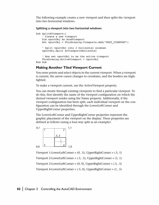
The following example creates a new viewport and then splits the viewport into two horizontal windows.
Splitting a viewport into two horizontal windows
Sub SplitAViewport() ’ Create a new viewport Dim vportObj As AcadViewport Set vportObj = ThisDrawing.Viewports.Add("TEST_VIEWPORT") ’ Split vportObj into 2 horizontal windows vportObj.Split acViewport2Horizontal ’ Now set vportObj to be the active viewport ThisDrawing.ActiveViewport = vportObjEnd Sub
Making Another Tiled Viewport CurrentYou enter points and select objects in the current viewport. When a viewport is current, the arrow cursor changes to crosshairs, and the borders are high-lighted.
To make a viewport current, use the ActiveViewport property.
You can iterate through existing viewports to find a particular viewport. To do this, first identify the name of the viewport configuration on which the desired viewport resides using the Name property. Additionally, if the viewport configuration has been split, each individual viewport on the con-figuration can be identified through the LowerLeftCorner and UpperRightCorner properties.
The LowerLeftCorner and UpperRightCorner properties represent the graphic placement of the viewport on the display. These properties are defined as follows (using a four-way split as an example):
Viewport 1-LowerLeftCorner = (0, .5), UpperRightCorner = (.5, 1)
Viewport 2-LowerLeftCorner = (.5, .5), UpperRightCorner = (1, 1)
Viewport 3-LowerLeftCorner = (0, 0), UpperRightCorner = (.5, .5)
Viewport 4-LowerLeftCorner = (.5, 0), UpperRightCorner = (1, .5)
1 2
3 4
0,1 1,1
0,0 1,0
.5,.5
82 | Chapter 3 Controlling the AutoCAD Environment
Splitting a viewport, then iterating through the windows
This example splits a viewport into four windows. It then iterates through all the viewports in the drawing and displays the viewport name, and the lower-left and upper-right corner for each viewport.
Sub Ch3_IteratingViewportWindows() ’ Create a new viewport and make it active Dim vportObj As AcadViewport Set vportObj = ThisDrawing.Viewports.Add("TEST_VIEWPORT") ThisDrawing.ActiveViewport = vportObj ’ Split vport into 4 windows vportObj.Split acViewport4 ’ Iterate through the viewports, ’ highlighting each viewport and displaying ’ the upper right and lower left corners ’ for each. Dim vport As AcadViewport Dim LLCorner As Variant Dim URCorner As Variant For Each vport In ThisDrawing.Viewports ThisDrawing.ActiveViewport = vport LLCorner = vport.LowerLeftCorner URCorner = vport.UpperRightCorner MsgBox "Viewport: " & vport.Name & " is now active." & _ vbCrLf & "Lower left corner: " & _ LLCorner(0) & ", " & LLCorner(1) & vbCrLf & _ "Upper right corner: " & _ URCorner(0) & ", " & URCorner(1) Next vportEnd Sub
Updating the Geometry in the Document Window
Many of the actions you perform through AutoCAD ActiveX Automation modify what is displayed in the AutoCAD drawing. Not all of these actions immediately update the display of the drawing. This is designed so you can make several changes to the drawing without waiting for the display to update after every single action. Instead, you can bundle your actions together and make a single call to update the display when you have finished.
The methods that will update the display are Update and Regen.
The Update method updates the display of a single object only. The Regen method regenerates the entire drawing and recomputes the screen coordi-nates and view resolution for all objects. It also reindexes the drawing database for optimum display and object selection performance.
Controlling the Drawing Windows | 83
Updating the display of a single object
This example creates a circle and then colors the circle red. It then updates the circle using the Update method so that the circle is visible in AutoCAD.
Sub Ch3_UpdateDisplay() Dim circleObj As AcadCircle Dim center(0 To 2) As Double Dim radius As Double center(0) = 1: center(1) = 1: center(2) = 0 radius = 1 ’ Create the circle and then color it red Set circleObj = ThisDrawing.ModelSpace.AddCircle(center, radius) circleObj.Color = acRed ’ Update the circle circleObj.UpdateEnd Sub
Resetting Active Objects
Changes to most active objects, such as the active layer and active linetype, will appear immediately. However, there are several active objects that must be reset for changes to appear. These objects are the active text style, the active UCS, and the active viewport. If changes are made to any of these objects, the object must be reset, and the Regen method must be called for the changes to appear.
To reset these objects, simply set the ActiveTextStyle, ActiveUCS, or Active-Viewport property, using the updated object.
Resetting the active viewport
The following example changes the display of the grid in the active viewport and then resets the viewport as the active viewport to display the change.
Sub Ch3_ResetActiveViewport() ’ Toggle the setting of the grid display ’ for the active viewport ThisDrawing.ActiveViewport.GridOn = _ Not (ThisDrawing.ActiveViewport.GridOn) ’ Reset the active viewport ThisDrawing.ActiveViewport = ThisDrawing.ActiveViewportEnd Sub
84 | Chapter 3 Controlling the AutoCAD Environment

Setting and Returning System Variables
The Document object provides the SetVariable and GetVariable methods for setting and retrieving AutoCAD system variables.
Setting the MAXSORT system variable
This example uses the SetVariable method to assign an integer to the MAXSORT system variable, which sets the maximum number of symbol names or block names sorted by listing commands.
ThisDrawing.SetVariable "MAXSORT", 100
Drawing with Precision
With AutoCAD you can create your drawings with precise geometry without performing tedious calculations. Often you can specify precise points with-out knowing the coordinates. Without leaving the drawing screen, you can perform calculations on your drawing and display various types of status information.
At this time, AutoCAD ActiveX Automation does not provide a method for the following AutoCAD capabilities:
■ Setting isometric snap and grid■ Setting object snaps■ Specifying measured intervals on objects or dividing objects into
segments
Adjusting Snap and Grid Alignment
You can use the grid as a visual guideline and turn on Snap mode to restrict cursor movement. In addition to setting the spacing, you can adjust the snap and grid alignment. You can rotate the alignment, or you can set it for use with isometric drawings.
Changing the Snap Angle and Base PointIf you need to draw along a specific alignment or angle, you can rotate the snap angle. This rotation realigns the crosshairs and constrains the cursor to the new alignment when Snap or Ortho mode is on. In the following exam-ple, the snap angle is adjusted to match the angle of the anchor bracket. With this adjustment, you can use the grid to draw objects at a 30-degree angle.
Setting and Returning System Variables | 85

The center point of the snap angle rotation is the snap base point. If you need to align a hatch pattern, you can change this point, which is normally set to 0,0.
To rotate the snap angle, use the SnapRotationAngle property. To change the base point of the snap angle rotation, use the SnapBasePoint property.
NOTE Both properties require a call to the Update method to update the AutoCAD display.
Changing the snap base point and rotation angle
This example changes the snap base point to (1,1) and the snap rotation angle to 30 degrees. The grid is turned on so that the changes are visible.
Sub Ch3_ChangeSnapBasePoint() ’ Turn on the grid for the active viewport ThisDrawing.ActiveViewport.GridOn = True ’ Change the snap base point to 1, 1 Dim newBasePoint(0 To 1) As Double newBasePoint(0) = 1: newBasePoint(1) = 1 ThisDrawing.ActiveViewport.SnapBasePoint = newBasePoint ’ Change the snap rotation angle to 30 degrees (0.575 radians) Dim rotationAngle As Double rotationAngle = 0.575 ThisDrawing.ActiveViewport.SnapRotationAngle = rotationAngle ’ reset the viewport ThisDrawing.ActiveViewport = ThisDrawing.ActiveViewportEnd Sub
Using Ortho Mode
As you draw lines or move objects, you can use Ortho mode to restrict the cursor to the horizontal or vertical axis. (The orthogonal alignment depends on the current snap angle or UCS.) Ortho mode works with activities that
default snap angle rotated snap angle
86 | Chapter 3 Controlling the AutoCAD Environment

require you to specify a second point. You can use Ortho not only to establish vertical or horizontal alignment but also to enforce parallelism or create reg-ular offsets.
By allowing AutoCAD to impose orthogonal restraints, you can draw more quickly. For example, you can create a series of perpendicular lines by turning on Ortho mode before you start drawing. Because the lines are constrained to the horizontal and vertical axes, you can draw faster, knowing that the lines are perpendicular.
As you move the cursor, a rubber-band line that defines the displacement fol-lows the horizontal or vertical axis, depending on which axis is nearest to the cursor. AutoCAD ignores Ortho mode in perspective views, or when you enter coordinates on the command line or specify an object snap.
To turn Ortho mode on or off, use the OrthoOn property. This property requires a Boolean for input. Set to TRUE to turn Ortho mode on, and to FALSE to turn Ortho mode off.
Turning Ortho mode on for the active viewport
ThisDrawing.ActiveViewport.OrthoOn = True
Drawing Construction Lines
You can create construction lines that extend to infinity in one or both direc-tions. Construction lines that extend in one direction are known as rays. Construction lines that extend in both directions are known as xlines. These construction lines can be used as a reference for creating other objects. For example, you can use construction lines to find the center of a triangle, pre-pare multiple views of the same item, or create temporary intersections that you can use for object snaps.
ortho mode on ortho mode off
Drawing with Precision | 87

Construction lines do not change the total area of the drawing; therefore, their infinite dimensions have no effect on zooming or viewpoints. You can move, rotate, and copy construction lines just as you move, rotate, and copy other objects. You may want to create construction lines on a construction line layer that can be frozen or turned off before plotting.
Creating Construction XLinesA construction xline can be placed anywhere in 3D space and extends to infinity in both directions. To create an xline, use the AddXLine method. This method specifies the line by the two-point method, you enter or select two points to define the orientation. The first point, the root, is considered the midpoint of the construction line.
Adding a construction line
The following example code creates an XLine object using the two points (5, 0, 0) and (1, 1, 0).
Sub Ch3_AddXLine() Dim xlineObj As AcadXline Dim basePoint(0 To 2) As Double Dim directionVec(0 To 2) As Double
construction lines
horizontal construction line
vertical construction line
88 | Chapter 3 Controlling the AutoCAD Environment

’ Define the xline basePoint(0) = 2#: basePoint(1) = 2#: basePoint(2) = 0# directionVec(0) = 1#: directionVec(1) = 1#: directionVec(2) = 0# ’ Create the xline in model space Set xlineObj = ThisDrawing.ModelSpace.AddXLine _ (basePoint, directionVec) ThisDrawing.Application.ZoomAllEnd Sub
Querying Construction XLinesOnce created, you can query the first point of a constuction xline using the BasePoint property. The second point used to create the xline is not stored with the object. Instead, use the DirectionVector property to obtain the direc-tional vector for the xline.
Querying a construction line
This example finds the base point and directional vector for the xline created above.
Dim BPoint As VariantDim Vector As Variant
Set BPoint = xlineObj.basePointSet Vector = xlineObj.DirectionVector
Creating RaysA ray is a line in 3D space that starts at a point you specify and extends to infinity. Unlike xline construction lines, which extend in two directions, rays extend in only one direction. As a result, rays help reduce the visual clutter caused by numerous construction lines.
Like construction lines, rays are ignored by commands that display the draw-ing extents.
Querying RaysOnce created, you can query the first point of a ray using the BasePoint prop-erty. The second point used to create the ray is not stored with the object. Instead, use the DirectionVector property to obtain the directional vector for the ray.
Drawing with Precision | 89

Adding, querying, and editing a Ray object
The following example code creates a Ray object using the two points (5, 0, 0) and (1, 1, 0). It then queries the current base point and direction vec-tor and displays the results in a message box. The direction vector is then changed and the base point and new direction vector are queried and displayed.
Sub Ch3_EditRay() Dim rayObj As AcadRay Dim basePoint(0 To 2) As Double Dim secondPoint(0 To 2) As Double ’ Define the ray basePoint(0) = 3#: basePoint(1) = 3#: basePoint(2) = 0# secondPoint(0) = 4#: secondPoint(1) = 4#: secondPoint(2) = 0# ’ Creates a Ray object in model space Set rayObj = ThisDrawing.ModelSpace.AddRay _ (basePoint, secondPoint) ThisDrawing.Application.ZoomAll ’ Find the current status of the Ray MsgBox "The base point of the ray is: " & _ rayObj.basePoint(0) & ", " & _ rayObj.basePoint(1) & ", " & _ rayObj.basePoint(2) & vbCrLf & _ "The directional vector for the ray is: " & _ rayObj.DirectionVector(0) & ", " & _ rayObj.DirectionVector(1) & ", " & _ rayObj.DirectionVector(2), , "Edit Ray" ’ Change the directional vector for the ray Dim newVector(0 To 2) As Double newVector(0) = -1 newVector(1) = 1 newVector(2) = 0 rayObj.DirectionVector = newVector ThisDrawing.Regen False MsgBox "The base point of the ray is: " & _ rayObj.basePoint(0) & ", " & _ rayObj.basePoint(1) & ", " & _ rayObj.basePoint(2) & vbCrLf & _ "The directional vector for the ray is: " & _ rayObj.DirectionVector(0) & ", " & _ rayObj.DirectionVector(1) & ", " & _ rayObj.DirectionVector(2), , "Edit Ray"End Sub
90 | Chapter 3 Controlling the AutoCAD Environment

Calculating Points and Values
By using the methods provided by the Utility object, you can quickly solve a mathematical problem or locate points on your drawing. By using methods on the Utility object, you can do the following:
■ Find the angle of a line from the X axis with the AngleFromXAxis method■ Convert an angle as a string to a real (double) value with the AngleToReal
method■ Convert an angle from a real (double) value to a string with the
AngleToString method■ Convert a distance from a string to a real (double) value with the
DistanceToReal method■ Create a variant that contains an array of integers, floating numbers, dou-
bles, and so forth, with the CreateTypedArray method■ Find the point at a specified angle and distance from a given point with
the PolarPoint method■ Translate a point from one coordinate system to another coordinate sys-
tem with the TranslateCoordinates method■ Find the distance between two points entered by the user with the
GetDistance method
Finding the distance between two points using the GetDistance method
This example uses the GetDistance method to obtain the point coordinates, and the MsgBox function to display the calculated distance.
Sub Ch3_GetDistanceBetweenTwoPoints() Dim returnDist As Double ’ Return the value entered by user. A prompt is provided. returnDist = ThisDrawing.Utility.GetDistance _ (, "Pick two points.") MsgBox "The distance between the two points is: " & returnDistEnd Sub
Calculating Areas
You can find the area of an arc, circle, ellipse, lightweight polyline, polyline, region, or planar-closed spline by using the Area property.
If you need to calculate the combined area of more than one object, you can keep a running total as you add or use the Boolean method on a series of regions to obtain a single region representing the desired area. From this sin-gle region you can use the Area property to obtain its area.
Drawing with Precision | 91

The calculated area differs according to the type of object you query.
■ Closed polylines and polygons: For wide polylines, this area is defined by the center of the width
■ Open objects such as open spline curves and open polylines: The area is com-puted as though a straight line connects the starting point and endpoint
■ Regions: The area is equal to the combined area for objects in the region
Calculating a Defined AreaYou can measure an arbitrary closed region defined by the 2D or 3D points specified by the user. The points must be coplanar.
open polyline
calculated area
polyline selected
closed polyline
calculated areapolyline selected
wide polyline
calculated areapolyline selected
92 | Chapter 3 Controlling the AutoCAD Environment

To obtain the area specified by points from the user
1 Use the GetPoint method in a loop to obtain the points from the user.
2 Create a lightweight polyline from the points provided by the user. Use the AddLightweightPolyline method to create the polyline.
3 Use the Area property to obtain the area of the newly created polyline.
4 Erase the polyline using the Erase method.
Calculating the area defined by points entered from the user
This example prompts the user to enter five points. A polyline is then created out of the points entered. The polyline is closed, and the area of the polyline is displayed in a message box.
Sub Ch3_CalculateDefinedArea() Dim p1 As Variant Dim p2 As Variant Dim p3 As Variant Dim p4 As Variant Dim p5 As Variant ’ Get the points from the user p1 = ThisDrawing.Utility.GetPoint(, vbCrLf & "First point: ") p2 = ThisDrawing.Utility.GetPoint(p1, vbCrLf & "Second point: ") p3 = ThisDrawing.Utility.GetPoint(p2, vbCrLf & "Third point: ") p4 = ThisDrawing.Utility.GetPoint(p3, vbCrLf & "Fourth point: ") p5 = ThisDrawing.Utility.GetPoint(p4, vbCrLf & "Fifth point: ") ’ Create the 2D polyline from the points Dim polyObj As AcadLWPolyline Dim vertices(0 To 9) As Double vertices(0) = p1(0): vertices(1) = p1(1) vertices(2) = p2(0): vertices(3) = p2(1) vertices(4) = p3(0): vertices(5) = p3(1) vertices(6) = p4(0): vertices(7) = p4(1) vertices(8) = p5(0): vertices(9) = p5(1) Set polyObj = ThisDrawing.ModelSpace.AddLightWeightPolyline _ (vertices) polyObj.Closed = True ThisDrawing.Application.ZoomAll ’ Display the area for the polyline MsgBox "The area defined the by points is " & _ polyObj.Area, , "Calculate Defined Area"End Sub
Drawing with Precision | 93

Prompting for User Input
The Utility object, which is a child of the Document object, defines the user input methods. The user input methods display a prompt on the AutoCAD command line and request input of various types. This type of user input is most useful for interactive input of screen coordinates, entity selection, and short-string or numeric values. If your application requires the input of numerous options or values, a dialog box may be more appropriate than individual prompts.
Each user input method displays a prompt on the AutoCAD command line and returns a value specific to the type of input requested. For example, GetString returns a string, GetPoint returns a variant (which contains a three-element array of doubles), and GetInteger returns an integer value. You can further control the input from the user with the InitializeUserInput method. This method lets you control things such as NULL input (pressing ENTER), input of zero or negative numbers, and input of arbitrary text values.
To force the prompt to display on a line by itself, use the carriage return/line-feed constant (vbCrLf) at the beginning of your prompt strings.
GetString Method
The GetString method prompts the user for input of a string at the AutoCAD command prompt. This method accepts two parameters. The first parameter controls the input of spaces in the input string. If it is set to 0, spaces are not allowed (SPACEBAR terminates the input); if set to 1, the string can contain spaces (ENTER must be used to terminate the input). The second parameter is the prompt string.
Getting a string value from the user at the AutoCAD command line
The following example displays the Enter Your Name prompt, and requires that the input from the user be terminated by pressing ENTER (spaces are allowed in the input string). The string value is stored in the retVal variable and is displayed using a message box.
Sub Ch3_GetStringFromUser() Dim retVal As String retVal = ThisDrawing.Utility.GetString _ (1, vbCrLf & "Enter your name: ") MsgBox "The name entered was: " & retValEnd Sub
The GetString method does not honor a prior call to the InitializeUserInput method.
94 | Chapter 3 Controlling the AutoCAD Environment

GetPoint Method
The GetPoint method prompts the user for the specification of a point at the AutoCAD command prompt. This method accepts two parameters, an optional from point and the prompt string. If the from point is provided, AutoCAD draws a rubber-band line from that point. To control the user input, this method can be preceded by a call to the InitializeUserInput method.
Getting a point selected by the user
The following example prompts the user for two points, then draws a line using those points as the start point and endpoint.
Sub Ch3_GetPointsFromUser() Dim startPnt As Variant Dim endPnt As Variant Dim prompt1 As String Dim prompt2 As String prompt1 = vbCrLf & "Enter the start point of the line: " prompt2 = vbCrLf & "Enter the end point of the line: " ’ Get the first point without entering a base point startPnt = ThisDrawing.Utility.GetPoint(, prompt1) ’ Use the point entered above as the base point endPnt = ThisDrawing.Utility.GetPoint(startPnt, prompt2) ’ Create a line using the two points entered ThisDrawing.ModelSpace.AddLine startPnt, endPnt ThisDrawing.Application.ZoomAllEnd Sub
GetKeyword Method
The GetKeyword method prompts the user for input of a keyword at the AutoCAD command prompt. This method accepts only one parameter, which is the prompt string. The keywords and input parameters are defined with a call to the InitializeUserInput method.
Prompting for User Input | 95

Getting a keyword from the user at the AutoCAD command line
The following example forces the user to enter a keyword by setting the first parameter of InitializeUserInput to 1, which disallows NULL input (pressing ENTER). The second parameter establishes the list of valid keywords.
Sub Ch3_KeyWord() Dim keyWord As String ThisDrawing.Utility.InitializeUserInput 1, "Line Circle Arc" keyWord = ThisDrawing.Utility.GetKeyword _ (vbCrLf & "Enter an option (Line/Circle/Arc): ") MsgBox keyWord, , "GetKeyword Example"End Sub
A more user-friendly keyword prompt is one that provides a default value if the user presses ENTER (NULL input). Notice the minor modifications to the following example:
Sub Ch3_KeyWord2() Dim keyWord As String ThisDrawing.Utility.InitializeUserInput 0, "Line Circle Arc" keyWord = ThisDrawing.Utility.GetKeyword _ (vbCrLf & "Enter an option (Line/Circle/<Arc>): ") If keyWord = "" Then keyWord = "Arc" MsgBox keyWord, , "GetKeyword Example"End Sub
Controlling User Input
You can use the InitializeUserInput method to define keywords or restrict the type of input to the user input method. The use and parameter values are similar to the AutoLISP initget function. InitializeUserInput can be used with the following methods: GetAngle, GetCorner, GetDistance, GetInteger, GetKeyword, GetOrientation, GetPoint, and GetReal. InitializeUserInput cannot be used with the GetString method. Use the GetInput method to retrieve the string value (keyword or arbitrary input) when the user input method does not return a string value.
The InitializeUserInput method accepts two parameters. The first parameter is a bit-coded integer value that determines the input options for the user input method. The second parameter is a string that defines the valid keywords.
Getting an integer value or a keyword from the user at the AutoCAD command line
The following example prompts the user for a positive, non-negative integer value or a keyword:
96 | Chapter 3 Controlling the AutoCAD Environment

Sub Ch3_UserInput() ’ The first parameter of InitializeUserInput (6) ’ restricts input to positive and non-negative ’ values. The second parameter is the list of ’ valid keywords. ThisDrawing.Utility.InitializeUserInput 6, "Big Small Regular" ’ Set the prompt string variable Dim promptStr As String promptStr = vbCrLf & "Enter the size or (Big/Small/<Regular>):" ’ Entering a keyword at the GetInteger prompt causes ’ an error; therefore to allow your application to ’ continue and check for the error description you ’ must set the error handler to resume on error. On Error Resume Next ’ Get the value entered by the user Dim returnInteger As Integer returnInteger = ThisDrawing.Utility.GetInteger(promptStr) ’ Check for an error. If the error description matches the ’ one shown below, then use GetInput to get the returned ’ string; otherwise, use the value of returnInteger. If Err.Description = "User input is a keyword" Then Dim returnString As String returnString = ThisDrawing.Utility.GetInput() Err.Clear Else If returnInteger = 0 Then ’If user pressed ENTER returnString = "Regular" ’Set to default Else ’Otherwise, returnString = returnInteger ’Use the value entered End If End If ’ Display the result MsgBox returnString, , "InitializeUserInput Example"End Sub
Accessing the AutoCAD Command Line
You can send commands directly to the AutoCAD command line by using the SendCommand method. The SendCommand method sends a single string to the command line. The string must contain the arguments to the command listed in the order expected by the prompt sequence of the exe-cuted command. A blank space or the ASCII equivalent of a carriage return in the string is equivalent to pressing ENTER on the keyboard. Unlike the AutoLISP environment, invoking the SendCommand method with no argu-ment is invalid.
Accessing the AutoCAD Command Line | 97

Sending a command to the AutoCAD command line
The following example creates a circle with a center of (2, 2, 0) and a radius of 4. The drawing is then zoomed to all the geometry in the drawing. Notice that there is a space at the end of the string which represents the final ENTER to begin execution of the command.
Sub Ch3_SendACommandToAutoCAD() ThisDrawing.SendCommand "_Circle 2,2,0 4 " ThisDrawing.SendCommand "_zoom a "End Sub
Working with No Documents Open
AutoCAD always starts up with a new or existing document open. It is possi-ble, however, to close all documents during the current session.
If you close all the documents in the AutoCAD user interface, you will notice a few changes to the application window. The available menus are reduced to simply the File, View, Window, and Help menus. These menus also have reduced available options on them. You will also notice that there is no com-mand line.
Similarly, the ActiveX interface only allows the following actions when no documents are open:
■ You can open a document■ You can create a new document■ You can import a document■ You can exit out of AutoCAD
These actions are all available from the Documents collection. The methods and properties of the Documents collection, in addition to a limited set of methods and properties of the Application object, are the only valid interface available when there are no documents open. If you perform any other action, such as attempting to access user options, your actions will result in an error.
Use the Count property on the Documents collection to determine if AutoCAD is in a zero document state. If Documents.Count = 0, then AutoCAD is in a zero document state. If Documents.Count > 0, then there is at least one drawing open.
It is also important to note that in VBA the ThisDrawing object is not defined when AutoCAD is in a zero document state. This makes sense since This-Drawing normally refers to the active drawing and in the zero document state
98 | Chapter 3 Controlling the AutoCAD Environment

there are no drawings open. Attempting to execute a macro that uses This-Drawing will result in a run-time error. To avoid the error, use the VBA GetO-bject function to obtain a connection to AutoCAD when there are no docu-ments open.
Importing Other File Formats
You can use drawings or images from other applications by opening them in specific formats. AutoCAD handles some form of conversion for DXF, SAT, BMP, and PostScript files. For all versions, you can import the file by using the Import method. This method takes three values as input: the name of the file to import, the insertion point in the drawing to place the file, and the scale factor to use when placing the imported drawing.
Exporting to Other File Formats
If you need to use an AutoCAD drawing in another application, you can con-vert it to a specific format by using the Export method. This method exports the AutoCAD drawing to a WMF, SAT, EPS, DXF, DWF, or BMP format. The Export method takes three values as input: the name for the new file to be created, the extension for the new file, and the selection set of objects to export, if required.
When exporting to WMF, SAT, or BMP formats, a nonempty selection set must be provided. This selection set specifies the objects from the drawing to export. If no selection set is specified, nothing is exported and a trappable invalid argument error results.
When exporting to EPS and DXF formats, you cannot specify a selection set. The entire drawing is automatically exported for these formats.
Importing Other File Formats | 99

Exporting a drawing as a DXF file and importing it again
This example creates a circle in the current drawing. It then exports the draw-ing to a file called DXFExprt.DXF. It then opens a new drawing and imports the file.
Sub Ch3_ImportingAndExporting()
’ Create the circle for visual representation Dim circleObj As AcadCircle Dim centerPt(0 To 2) As Double Dim radius As Double centerPt(0) = 2: centerPt(1) = 2: centerPt(2) = 0 radius = 1 Set circleObj = ThisDrawing.ModelSpace.AddCircle _ (centerPt, radius) ThisDrawing.Application.ZoomAll ’ Create an empty selection set Dim sset As AcadSelectionSet Set sset = ThisDrawing.SelectionSets.Add("NEWSSET") ’ Export the current drawing to the file specified above. Dim exportFile As String exportFile = "C:\AutoCAD\DXFExprt" ThisDrawing.Export exportFile, "DXF", sset ’ Open a new drawing ThisDrawing.Application.Documents.Add "acad.dwt" ’ Define the import Dim importFile As String Dim insertPoint(0 To 2) As Double Dim scalefactor As Double importFile = "C:\AutoCAD\DXFExprt.dxf" insertPoint(0) = 0: insertPoint(1) = 0: insertPoint(2) = 0 scalefactor = 2# ’ Import the file ThisDrawing.Import importFile, insertPoint, scalefactor ThisDrawing.Application.ZoomAll End Sub
100 | Chapter 3 Controlling the AutoCAD Environment

In This Chapter
Creating and Editing AutoCAD Entities
4■ Creating Objects
■ Editing Objects
■ Using Layers, Colors, and Linetypes
■ Adding Text to Drawings
You can create a range of objects, from simple lines and
circles to spline curves, ellipses, and associative hatch
areas. In general, you add objects to model space using
one of the Add methods. You can also create objects in
paper space, or in a block.
Once an object is created, you can change the layer,
color, and linetype of the object. You can also add text
to annotate your drawing.
101

Creating Objects
While there are often several different ways to create the same graphical object in AutoCAD, ActiveX Automation offers only one creation method per object. For example, in AutoCAD there are four different ways you can create a circle: (1) by specifying the center and radius, (2) by two points defin-ing the diameter, (3) by three points defining the circumference, or (4) by two tangents and a radius. However, in ActiveX Automation there is only one creation method provided to create a circle, and that method uses the center and radius.
NOTE The VB and VBA methods of creating objects using either CreateObject or Dim with the New keyword can only be used to create the AutoCAD Applica-tion object. All other AutoCAD objects must be created using the Add or Add<object> methods provided in the AutoCAD interface.
Determining the Container Object
Graphical objects are created in either the ModelSpace collection, PaperSpace collection, or a Block object.
The ModelSpace collection is returned by the ModelSpace property and the PaperSpace collection by the PaperSpace property.
You can reference these objects directly, or through a user-defined variable. To reference the objects directly, include the object in the calling hierarchy. For example, the following statement adds a line to the model space:
Set lineObj = ThisDrawing.ModelSpace.AddLine(startPoint,endPoint)
To reference the objects through a user-defined variable, define the variable as type AcadModelSpace or AcadPaperSpace, and then set the variable to the appropriate property of the active document. The following example defines two variables and sets them equal to the current model space and paper space, respectively:
Dim moSpace As AcadModelSpaceDim paSpace As AcadPaperSpaceSet moSpace = ThisDrawing.ModelSpaceSet paSpace = ThisDrawing.PaperSpace
The following statement adds a line to the model space using the user-defined variable:
Set lineObj = moSpace.AddLine(startPoint,endPoint)
102 | Chapter 4 Creating and Editing AutoCAD Entities

Creating Lines
The line is the most basic object in AutoCAD. You can create a variety of lines—single lines, and multiple line segments with and without arcs. In gen-eral, you draw lines by specifying coordinate points. The default linetype is CONTINUOUS, an unbroken line, but various linetypes are available that use dots and dashes.
To create a line, use one of the following methods:
AddLine Creates a line passing through two points.
AddLightweightPolyline
Creates a 2D lightweight polyline from a list of vertices.
AddMLine Creates a multiline
AddPolyline Creates a 2D or 3D polyline
Standard lines and multilines are created on the XY plane of the WCS. Polylines and Lightweight Polylines are created in the Object Coordinate Sys-tem (OCS). For information on converting OCS coordinates, see “Converting Coordinates” on page 259.
Creating a Polyline object
This example uses the AddLightweightPolyline method to create a simple two-segment polyline using the 2D coordinates (2,4), (4,2), and (6,4).
Sub Ch4_AddLightWeightPolyline() Dim plineObj As AcadLWPolyline Dim points(0 To 5) As Double ’ Define the 2D polyline points points(0) = 2: points(1) = 4 points(2) = 4: points(3) = 2 points(4) = 6: points(5) = 4 ’ Create a light weight Polyline object in model space Set plineObj = ThisDrawing.ModelSpace. _ AddLightWeightPolyline(points) ThisDrawing.Application.ZoomAllEnd Sub
Creating Curved Objects
You can create a variety of curved objects with AutoCAD, including spline curves, circles, arcs, and ellipses. All curves are created on the XY plane of the current WCS.
Creating Objects | 103

To create a curve, use one of the following methods:
AddArc Creates an arc given the center, radius, start and end angles.
AddCircle Creates a circle given the center point and radius.
AddEllipse Creates an ellipse given the center point, a point on the major axis, and the radius ratio.
AddSpline Creates a quadratic or cubic NURBS (nonuniform rational B-spline) curve.
Creating a Spline object
This example creates a spline in model space using three points (0, 0, 0), (5, 5, 0), and (10, 0, 0). The spline has start and end tangents of (0.5, 0.5, 0.0).
Sub Ch4_CreateSpline() ’ This example creates a spline object in model space. ’ Declare the variables needed Dim splineObj As AcadSpline Dim noOfPoints As Integer Dim startTan(0 To 2) As Double Dim endTan(0 To 2) As Double Dim fitPoints(0 To 8) As Double ’ Define the variables noOfPoints = 3 startTan(0) = 0.5: startTan(1) = 0.5: startTan(2) = 0 endTan(0) = 0.5: endTan(1) = 0.5: endTan(2) = 0 fitPoints(0) = 1: fitPoints(1) = 1: fitPoints(2) = 0 fitPoints(3) = 5: fitPoints(4) = 5: fitPoints(5) = 0 fitPoints(6) = 10: fitPoints(7) = 0: fitPoints(8) = 0 ’ Create the spline Set splineObj = ThisDrawing.ModelSpace.AddSpline _ (fitPoints, startTan, endTan) ZoomAllEnd Sub
For more information on splines, see the Spline object and AddSpline method documentation in the AutoCAD ActiveX and VBA Reference.
Creating Point Objects
Point objects can be useful, for example, as node or reference points that you can snap to and offset objects from. You can set the style of the point and its size relative to the screen or in absolute units.
104 | Chapter 4 Creating and Editing AutoCAD Entities

Controlling the Appearance of PointsThe PDMODE and PDSIZE system variables control the appearance of Point objects. The PDMODE values 0, 2, 3, and 4 specify a figure to draw through the point. A value of 1 selects nothing to be displayed.
Adding 32, 64, or 96 to the previous value selects a shape to draw around the point in addition to the figure drawn through it:
PDSIZE controls the size of the point figures, except for PDMODE values 0 and 1. A 0 setting generates the point at 5 percent of the graphics area height. A positive PDSIZE value specifies an absolute size for the point figures. A nega-tive value is interpreted as a percentage of the viewport size. The size of all points is recalculated when the drawing is regenerated.
After you change PDMODE and PDSIZE, the appearance of existing points changes the next time the drawing is regenerated.
To set PDMODE and PDSIZE, use the SetVariable method.
0 2 3 431
32 34 35 3633
64 66 67 6865
96 98 99 10097
34
Creating Objects | 105

Creating a Point object and changing its appearance
The following code example creates a Point object in model space at the coor-dinate (5, 5, 0). The PDMODE and PDSIZE system variables are then updated.
Sub Ch4_CreatePoint() Dim pointObj As AcadPoint Dim location(0 To 2) As Double ’ Define the location of the point location(0) = 5#: location(1) = 5#: location(2) = 0# ’ Create the point Set pointObj = ThisDrawing.ModelSpace.AddPoint(location) ThisDrawing.SetVariable "PDMODE", 34 ThisDrawing.SetVariable "PDSIZE", 1 ZoomAllEnd Sub
Creating Solid-Filled Areas
You can create triangular and quadrilateral areas filled with a color. For quicker results, create these areas with the FILLMODE system variable off, then turn FILLMODE on to fill the finished area.
When you create a quadrilateral solid-filled area, the sequence of the third and fourth points determines its shape. Compare the following illustrations:
The first two points define one edge of the polygon. The third point is defined diagonally opposite from the second. If the fourth point is set equal to the third point, then a filled triangle is created.
To create a solid-filled area, use the AddSolid method.
solid-filled areas
1
3
2
4
1
4
2
3
106 | Chapter 4 Creating and Editing AutoCAD Entities

Creating a solid-filled object
The following code example creates a quadrilateral solid in model space using the coordinates (0, 0, 0), (5, 0, 0), (5, 8, 0), and (0, 8, 0).
Sub Ch4_CreateSolid() Dim solidObj As AcadSolid Dim point1(0 To 2) As Double Dim point2(0 To 2) As Double Dim point3(0 To 2) As Double Dim point4(0 To 2) As Double ’ Define the solid point1(0) = 0#: point1(1) = 0#: point1(2) = 0# point2(0) = 5#: point2(1) = 0#: point2(2) = 0# point3(0) = 5#: point3(1) = 8#: point3(2) = 0# point4(0) = 0#: point4(1) = 8#: point4(2) = 0# ’ Create the solid object in model space Set solidObj = ThisDrawing.ModelSpace.AddSolid _ (point1, point2, point3, point4) ZoomAllEnd Sub
Creating Regions
Regions are two-dimensional enclosed areas you create from closed shapes called loops. A loop is a curve or a sequence of connected curves that defines an area on a plane with a boundary that does not intersect itself. Loops can be combinations of lines, lightweight polylines, circles, arcs, ellipses, ellipti-cal arcs, splines, 3D faces, traces, and solids. The objects that make up the loops must either be closed or form closed areas by sharing endpoints with other objects. They must also be coplanar (on the same plane).
If the open curves intersect in their interior, they cannot form a region.
Objects such as 3D polylines and face meshes can be converted to regions by being exploded. You cannot form regions from open objects that intersect to form a closed area: for example, intersecting arcs or self-intersecting curves.
The loops that make up a region must be defined as an array of objects.
Creating Objects | 107

You can apply hatching and shading to regions and you can analyze proper-ties such as their area and moments of inertia. You can create shapes, then select objects to create regions.
To create a region, use the AddRegion method. This method will create a region out of every closed loop formed by the input array of curves. AutoCAD converts closed 2D and planar 3D polylines to separate regions, then con-verts polylines, lines, and curves that form closed planar loops. If more than two curves share an endpoint, the resulting region might be arbitrary. Because of this, several regions may actually be created when using the AddRegion method. Use a variant to hold the newly created array of regions.
To calculate the total number of Region objects created, use the UBound and LBound Visual Basic functions. For example, the following statement illus-trates using these objurgating:
UBound(objRegions) - LBound(objRegions) + 1
where objRegions is a variant containing the return value from AddRegion. This statement will calculate the total number of regions created.
Creating a simple region
The following code example creates a region from a single circle.
Sub Ch4_CreateRegion() ’ Define an array to hold the ’ boundaries of the region. Dim curves(0 To 0) As AcadCircle ’ Create a circle to become a ’ boundary for the region. Dim center(0 To 2) As Double Dim radius As Double center(0) = 2 center(1) = 2 center(2) = 0 radius = 5# Set curves(0) = ThisDrawing.ModelSpace.AddCircle _ (center, radius) ’ Create the region Dim regionObj As Variant regionObj = ThisDrawing.ModelSpace.AddRegion(curves) ZoomAllEnd Sub
108 | Chapter 4 Creating and Editing AutoCAD Entities

Creating Composite RegionsYou can create composite regions by subtracting, combining, or finding the intersection of regions or 3D solids. You can then extrude or revolve compos-ite regions to create complex solids. To create a composite region, use the Boolean method.
When you subtract one region from another, you call the Boolean method from the first region. This is the region from which you want to subtract. For example, to calculate how much carpeting is needed for a floorplan, call the Boolean method from the outer boundary of the floor space and use the uncarpeted areas, such as pillars and counters, as the object in the Boolean parameter list.
Creating a composite region
Sub Ch4_CreateCompositeRegions() ’ Create two circles, one representing a room, ’ the other a pillar in the center of the room Dim RoomObjects(0 To 1) As AcadCircle Dim center(0 To 2) As Double Dim radius As Double center(0) = 4 center(1) = 4 center(2) = 0 radius = 2# Set RoomObjects(0) = ThisDrawing.ModelSpace. _ AddCircle(center, radius) radius = 1# Set RoomObjects(1) = ThisDrawing.ModelSpace. _ AddCircle(center, radius) ’ Create a region from the two circles Dim regions As Variant regions = ThisDrawing.ModelSpace.AddRegion(RoomObjects) ’ Copy the regions into the region variables for ease of use Dim RoundRoomObj As AcadRegion Dim PillarObj As AcadRegion If regions(0).Area > regions(1).Area Then ’ The first region is the room Set RoundRoomObj = regions(0) Set PillarObj = regions(1) Else ’ The first region is the pillar Set PillarObj = regions(0) Set RoundRoomObj = regions(1) End If
Creating Objects | 109

’ Color the room object red and the pillar object cyan RoundRoomObj.Color = acRed PillarObj.Color = acCyan ZoomAll ’ Subtract the pillar space from the floor space to ’ get a region that represents the total carpet area. RoundRoomObj.Boolean acSubtraction, PillarObj ’ Use the Area property to determine the total carpet area MsgBox "The carpet area is: " & RoundRoomObj.AreaEnd Sub
Find the area of the resulting region with the Area property.
To unite regions, call the Boolean method and enter the constant acUnion for the operation instead of acSubtraction. To find the intersection of two regions, use the constant acIntersection. You can combine regions in any order to unite or intersect them.
The following illustration shows the uniting of two regions:
The following illustration shows the intersection of three regions:
regions selected result - a composite region
selected intersected regions result
110 | Chapter 4 Creating and Editing AutoCAD Entities

Creating Hatches
Hatching fills a specified area in a drawing with a pattern.
When creating a hatch, you do not initially specify the area to be filled. First you must create the Hatch object. Once this is done, you can specify the outer loop, which is the outermost boundary for the hatch. You can then continue to specify any inner loops that may exist in the hatch.
Creating the Hatch ObjectWhen creating the Hatch object, you specify the hatch pattern type, the hatch pattern name, and the associativity. Once the Hatch object has been created, you will not be able to change the hatch associativity.
To create a Hatch object, use the AddHatch method.
Associating a HatchYou can create associative or nonassociative hatches. Associative hatches are linked to their boundaries and updated when the boundaries are modified. Nonassociative hatches are independent of their boundaries.
Associativity can only be set when a hatch is created. Once a hatch has been created, you can unassociate it, but you cannot associate it again.
To make a hatch associative, set the Associativity parameter of the AddHatch method to TRUE. To make a hatch nonassociative, set the Associativity parameter of the AddHatch method to FALSE.
Assigning the Hatch Pattern Type and NameAutoCAD supplies a solid-fill and more than fifty industry-standard hatch patterns. Hatch patterns highlight a particular feature or area of a drawing. For example, patterns can help differentiate the components of a 3D object or represent the materials that make up an object.
You can use a pattern supplied with AutoCAD or one from an external pat-tern library. For a table of the hatch patterns supplied with AutoCAD, see appendix E, “Standard Libraries” in the AutoCAD Command Reference.
Creating Objects | 111

To specify a unique pattern, you must enter both a pattern type and a pattern name when creating the Hatch object. The pattern type specifies where to look up the pattern name. When entering the pattern type, use one of the following constants:
acHatchPatternTypePredefined
Selects the pattern name from those defined in the acad.pat file.
acHatchPatternTypeUserDefined
Defines a pattern of lines using the current linetype.
acHatchPatternTypeCustomDefined
Selects the pattern name from a PAT other than the acad.pat file.
When entering the pattern name, use a name that is valid for the file speci-fied by the pattern type.
Defining the Hatch BoundariesOnce the Hatch object is created, the hatch boundaries can be added. Bound-aries can be any combination of lines, arcs, circles, 2D polylines, ellipses, splines, and regions.
The first boundary added must be the outer boundary, which defines the outer most limits to be filled by the hatch. To add the outer boundary, use the AppendOuterLoop method.
Once the outer boundary is defined, you can continue adding inner bound-aries. Add inner boundaries with the AppendInnerLoop method.
Inner boundaries define islands within the hatch. How these islands are han-dled by the Hatch object depends on the setting of the HatchStyle property. The HatchStyle property can be set to one of the following conditions:
Hatch style definitions
HatchStyle Condition Description
Normal Specifies standard style, or normal. This option hatches inward from the outermost area boundary. If AutoCAD encounters an internal boundary, it turns off hatching until it encounters another boundary. This is the default setting for the HatchStyle property.
112 | Chapter 4 Creating and Editing AutoCAD Entities

When you have finished defining the hatch it must be evaluated before it can be displayed. Use the Evaluate method to do this.
Creating a Hatch object
This example creates an associate hatch in model space. Once the hatch has been created, you can change the size of the circle that the hatch is associated with. The hatch will change to match the current circle size.
Sub Ch4_CreateHatch() Dim hatchObj As AcadHatch Dim patternName As String Dim PatternType As Long Dim bAssociativity As Boolean ’ Define the hatch patternName = "ANSI31" PatternType = 0 bAssociativity = True ’ Create the associative Hatch object Set hatchObj = ThisDrawing.ModelSpace.AddHatch _ (PatternType, patternName, bAssociativity)
Outer Fills the outermost areas only. This style also hatches inward from the area boundary, but it turns off hatching if it encounters an internal boundary and does not turn it back on again.
Ignore Ignores internal structure. This option hatches through all internal objects.
Hatch style definitions (continued)
HatchStyle Condition Description
Creating Objects | 113
’ Create the outer boundary for the hatch. (a circle) Dim outerLoop(0 To 0) As AcadEntity Dim center(0 To 2) As Double Dim radius As Double center(0) = 3: center(1) = 3: center(2) = 0 radius = 1 Set outerLoop(0) = ThisDrawing.ModelSpace. _ AddCircle(center, radius) ’ Append the outerboundary to the hatch ’ object, and display the hatch hatchObj.AppendOuterLoop (outerLoop) hatchObj.Evaluate ThisDrawing.Regen True End Sub
Editing Objects
To modify an existing object, use the methods and properties associated with that object. If you modify a visible property of a graphic object, use the Update method to redraw the object onscreen.
This section describes how to edit 2D objects.
Working with Named Objects
In addition to the graphic objects used by AutoCAD, there are several types of nongraphic objects stored in drawing files. These objects have descriptive designations associated with them, for example, blocks, layers, groups, and dimension styles. In most cases, you name objects as you create them, and rename them later. Names are stored in symbol tables. When you specify a named object, you are referencing the name and associated data of the object in the symbol table.
Purging Named ObjectsYou can purge unused, unreferenced named objects from a drawing at any time during an editing session. Purging reduces drawing size. You cannot purge objects that are referenced by other objects. For example, a font file might be referenced by a text style. A layer is referenced by the objects on the layer.
To purge a drawing, use the PurgeAll method.
Purging a drawing
ThisDrawing.PurgeAll
114 | Chapter 4 Creating and Editing AutoCAD Entities

Renaming ObjectsAs your drawings become more complex, you can rename objects to keep the names meaningful or to avoid conflicts with names in other drawings you have inserted in the main drawings.
You can rename any named object except those that AutoCAD names by default, for example, layer 0 or the CONTINUOUS linetype.
Names can be up to 255 characters long. In addition to letters and numbers, names can contain spaces (although AutoCAD removes spaces that appear directly before and after a name) and any special character not used by Microsoft Windows or AutoCAD for other purposes. Special characters that you cannot use include less-than and greater-than symbols (< >), forward slashes and backslashes (/ \), quotation marks ("), colons (:), semicolons (;), question marks (?), commas (,), asterisks (*), vertical bars (|), equal signs (=), and backquotes (’). You also cannot use special characters created with Unicode fonts.
To rename an object, use the Name property for that object.
Renaming a layer
This example creates a layer called “NewLayer” and then renames the layer to “MyLayer”.
Sub Ch4_RenamingLayer() ’ Create a layer Dim layerObj As AcadLayer Set layerObj = ThisDrawing.Layers.Add("NewLayer") ’ Change the name of the layer layerObj.Name = "MyLayer" End Sub
Selecting Objects
A selection set is a group of AutoCAD objects specified for processing as a sin-gle unit. A selection set can consist of a single object, or it can be a more com-plex grouping: for example, the set of objects of a certain color on a certain layer.
Defining a selection set is a two-step process. First, you must create a new selection set and add it to the SelectionSets collection. Once created, you then populate the selection set with the objects you want to process.
Editing Objects | 115

Creating a Selection SetTo create a named selection set, use the Add method. This method requires only a single parameter—the name of the selection set.
Creating an empty selection set
This example creates a new selection set.
Sub Ch4_CreateSelectionSet() Dim selectionSet1 As AcadSelectionSet Set selectionSet1 = ThisDrawing.SelectionSets. _ Add("NewSelectionSet")End Sub
Adding Objects to a Selection SetYou can add objects to the active selection set by using any of the following methods:
AddItem Adds one or more objects to the specified selection set.
Select Selects objects and places them into the active selection set. You can select all objects, objects within and crossing a rectangular area, objects within and crossing a polygon area, all objects crossing a fence, the most recently created object, the objects in the most recent selection set, objects within a window, or objects within a window polygon.
SelectAtPoint Selects objects passing through a given point and places them into the active selection set.
SelectByPolygon
Selects objects within a fence and adds them to the active selection set.
SelectOnScreen
Prompts the user to pick objects from the screen and adds them into the active selection set.
116 | Chapter 4 Creating and Editing AutoCAD Entities

Adding objects to a selection set
This example prompts the user to select objects, then adds those objects to the selection set. Then it changes the color of the objects in the selection set to blue.
Sub Ch4_AddToASelectionSet() ’ Create a new selection set Dim sset As AcadSelectionSet Set sset = ThisDrawing.SelectionSets.Add("SS1") ’ Prompt the user to select objects ’ and add them to the selection set. ’ To finish selecting, press ENTER. sset.SelectOnScreen ’ Iterate through the selection set ’ and color each object blue Dim entry As AcadEntity For Each entry In sset entry.Color = acBlue entry.Update Next entryEnd Sub
Filtering Selection SetsYou can limit selection sets by property, such as color, or by object type using filter lists. For example, you can copy only the red objects in a circuit board drawing or only objects on a certain layer.
NOTE Filtering recognizes only colors or linetypes explicitly assigned to objects, not those inherited by the layer.
To use the filtering mechanism, supply both the filter type and the filter data that will be sorted on. The filter type is a code that specifies which filter to use. AutoCAD ActiveX Automation uses the DXF group codes to specify the filter types. A few of the most common filter types are listed here. For a com-plete list, see the AutoCAD DXF Reference.
DXF codes for common filters
DXF code Filter type
0 Object Type (String)Such as “Line,” “Circle,” “Arc,” and so forth.
2 Object Name (String)The table (given) name of a named object.
Editing Objects | 117

The following examples demonstrate various filters.
Add only Text objects to the selection set:
FilterType = 0FilterData = "TEXT"sset.SelectOnScreen FilterType, FilterData
Add only Line objects to the selection set:
FilterType = 0FilterData = "LINE"sset.SelectOnScreen FilterType, FilterData
Add only objects that are on layer FLOOR9 to the selection set:
FilterType = 8FilterData = "FLOOR9"sset.SelectOnScreen FilterType, FilterData
Add only objects that are red to the selection set:
Filter Type = 62Filter Data = 5sset.SelectOnScreen FilterType, FilterData
Removing Objects from a Selection SetAfter you create a selection set, you can choose to remove individual objects, or all the objects from that set. For example, you can select an entire group of densely grouped objects and remove specific objects within the group, leaving only the objects you want to be in the set.
8 Layer Name (String)Such as “Layer 0.”
60 Object Visibility (Integer)Use 0 = visible, 1 = invisible.
62 Color Number (Integer)Numeric index values ranging from 0 to 256.Zero indicates the BYBLOCK. 256 indicates BYLAYER. A negative value indicates that the layer is turned off.
67 Model/paper space indicator (Integer)Use 0 or omitted = model space,1 = paper space.
DXF codes for common filters (continued)
DXF code Filter type
118 | Chapter 4 Creating and Editing AutoCAD Entities

Use the following methods to remove items from the selection set:
RemoveItems The RemoveItems method removes one or more items from a selection set. The removed items still exist, but they no longer reside in the selection set.
Clear The Clear method will empty the selection set. The selection set will still exist, but contains no items. The items that previously resided in the selection still exist, but they no longer reside in the selection set.
Erase The Erase method deletes all items in a selection set. The selection set still exists, but will contain no items. The items that previously resided in the selection set no longer exist.
Delete The Delete method deletes a selection set and all items in the selection set. Neither the selection set, nor the items previously in the selection set will exist after a call to the Delete method.
Copying Objects
You can copy single or multiple objects within the current drawing. Offset-ting creates new objects at a specified distance from selected objects, or through a specified point. Mirroring creates a mirror image of objects in a specified mirror line. Arraying creates sets of copied objects in a rectangular or circular pattern.
NOTE You cannot perform any of the following methods while simultaneously iterating through a collection. An iteration will open the workspace for a read-only operation while this method attempts to perform a read-write operation. Complete any iteration of a collection before you call these methods.
Copying an Object to the Same LocationTo copy a single object, use the Copy method provided for that object. This method creates a new object that is a duplicate of the original object. The new object is located at the same position as the original, and is returned by the method.
Editing Objects | 119

Copying Multiple Objects or Copying to Different DocumentsTo copy multiple objects, use the CopyObjects method or create an array of objects to use with the Copy method. (To copy the objects in a selection set, iterate through the selection set and save the objects into an array.) Iterate through the array, copying each object individually, and collect the newly created objects in a second array.
Copying multiple objects
This example creates two Circle objects and uses the CopyObjects method to make a copy of the circles.
Sub Ch4_CopyCircleObjects() Dim ACADApp As AcadApplication Dim DOC1 As AcadDocument Dim circleObj1 As AcadCircle Dim circleObj2 As AcadCircle Dim circleObj1Copy As AcadCircle Dim circleObj2Copy As AcadCircle Dim centerPoint(0 To 2) As Double Dim radius1 As Double Dim radius2 As Double Dim radius1Copy As Double Dim radius2Copy As Double Dim objCollection(0 To 1) As Object Dim retObjects As Variant ’ Define the Circle object centerPoint(0) = 0: centerPoint(1) = 0: centerPoint(2) = 0 radius1 = 5#: radius2 = 7# radius1Copy = 1#: radius2Copy = 2# ’ Get application object from system Set ACADApp = GetObject(, "AutoCAD.Application") ’ Create a new drawing Set DOC1 = ACADApp.Documents.Add ’ Add two circles to the drawing Set circleObj1 = DOC1.ModelSpace.AddCircle _ (centerPoint, radius1) Set circleObj2 = DOC1.ModelSpace.AddCircle _ (centerPoint, radius2) ZoomAll ’ Put the objects to be copied into a form ’ compatible with CopyObjects Set objCollection(0) = circleObj1 Set objCollection(1) = circleObj2
120 | Chapter 4 Creating and Editing AutoCAD Entities

’ Copy object and get back a collection of ’ the new objects (copies) retObjects = DOC1.CopyObjects(objCollection) ’ Get newly created object and apply ’ new properties to the copies Set circleObj1Copy = retObjects(0) Set circleObj2Copy = retObjects(1) circleObj1Copy.radius = radius1Copy circleObj1Copy.Color = acRed circleObj2Copy.radius = radius2Copy circleObj2Copy.Color = acRed ZoomAllEnd Sub
Offsetting ObjectsOffsetting an object creates a new object at a specified offset distance from the original object. You can offset arcs, circles, ellipses, lines, lightweight polylines, polylines, splines, and xlines.
To offset an object, use the Offset method provided for that object.
The only input to this method is the distance to offset the object. If this dis-tance is negative, it is interpreted by AutoCAD as being an offset to make a “smaller” curve (that is, for an arc it would offset to a radius that is the given distance less than the starting curve’s radius). If “smaller” has no meaning, then AutoCAD would offset in the direction of smaller X,Y, Z WCS coordi-nates. If the offset distance is invalid then an error is returned.
For many objects, the result of this operation will be a single new curve (which may not be of the same type as the original curve). For example, off-setting an ellipse will result in a spline because the result does fit the equation of an ellipse. In some cases it may be necessary for the offset result to be sev-eral curves. Because of this, the method returns the new object, or array of objects, as a variant.
offset polylines
Editing Objects | 121

Offsetting a polyline
This example creates a lightweight polyline and then offsets the polyline. The newly offset polyline is colored red.
Sub Ch4_OffsetPolyline() ’ Create the polyline Dim plineObj As AcadLWPolyline Dim points(0 To 11) As Double points(0) = 1: points(1) = 1 points(2) = 1: points(3) = 2 points(4) = 2: points(5) = 2 points(6) = 3: points(7) = 2 points(8) = 4: points(9) = 4 points(10) = 4: points(11) = 1 Set plineObj = ThisDrawing.ModelSpace. _ AddLightWeightPolyline(points) plineObj.Closed = True ZoomAll ’ Offset the polyline Dim offsetObj As Variant offsetObj = plineObj.Offset(0.25) offsetObj(0).Color = acRed ZoomAllEnd Sub
Mirroring ObjectsMirroring creates a mirror image copy of an object around an axis or mirror line. You can mirror all drawing objects.
To mirror an object, use the Mirror method provided for that object. Unlike the mirror command in AutoCAD, this method places the reflected image into the drawing and retains the original object. (To remove the original object, use the Erase method.)
This method requires two coordinates as input. The two coordinates speci-fied become the endpoints of the mirror line around which the base object is reflected. In 3D, this line orients a mirroring plane perpendicular to the XY plane of the UCS containing the mirror line.
selected objects mirrored objectmirror line
122 | Chapter 4 Creating and Editing AutoCAD Entities

To manage the reflection properties of Text objects, use the MIRRTEXT system variable. The default setting of MIRRTEXT is On (1), which causes Text objects to be mirrored just as any other object. When MIRRTEXT is off (0), text is not mirrored. Use the GetVariable and SetVariable methods to query and set the MIRRTEXT setting.
You can mirror a Viewport object in paper space, although doing so has no effect on its model space view or on model space objects.
Mirroring a polyline about an axis
This example creates a lightweight polyline and mirrors that polyline about an axis. The newly created polyline is colored red.
Sub Ch4_MirrorPolyline() ’ Create the polyline Dim plineObj As AcadLWPolyline Dim points(0 To 11) As Double points(0) = 1: points(1) = 1 points(2) = 1: points(3) = 2 points(4) = 2: points(5) = 2 points(6) = 3: points(7) = 2 points(8) = 4: points(9) = 4 points(10) = 4: points(11) = 1 Set plineObj = ThisDrawing.ModelSpace. _ AddLightWeightPolyline(points) plineObj.Closed = True ZoomAll ’ Define the mirror axis Dim point1(0 To 2) As Double Dim point2(0 To 2) As Double point1(0) = 0: point1(1) = 4.25: point1(2) = 0 point2(0) = 4: point2(1) = 4.25: point2(2) = 0 ’ Mirror the polyline Dim mirrorObj As AcadLWPolyline Set mirrorObj = plineObj.Mirror(point1, point2) mirrorObj.Color = acRed ZoomAllEnd Sub
before mirroring after mirroring (MIRRTEXT=1)
after mirroring (MIRRTEXT=0)
Editing Objects | 123

Arraying ObjectsYou can copy an object in polar or rectangular arrays. For polar arrays, you control the number of copies of the object and the angle to fill the array to. For rectangular arrays, you control the number of rows and columns and the distance between them.
Creating Polar ArraysYou can array all drawing objects. To create a polar array, use the ArrayPolar method provided for that object. This method requires you to provide the number of objects to create, the angle-to-fill, and the center point for the array. The number of objects must be a positive integer greater than 1. The angle-to-fill must be in radians. A positive value specifies counterclockwise rotation. A negative value specifies clockwise rotation. An error is returned for an angle that equals 0. The center point is a variant array containing three doubles. These doubles represent the 3D WCS coordinate specifying the cen-ter point for the polar array.
AutoCAD determines the distance from the array’s center point to a reference point on the original object. The reference point used depends on the type of object. AutoCAD uses the center point of a circle or arc, the insertion point of a block or shape, the start point of text, and one endpoint of a line or trace.
This method does not support the Rotate While Copying option of the AutoCAD ARRAY command.
(0,0,0)
polar array
a
b
base object
rectangular array
124 | Chapter 4 Creating and Editing AutoCAD Entities

Creating a polar array
This example creates a circle, and then performs a polar array of the circle. This creates four circles filling 180 degrees around a base point of (4, 4, 0).
Sub Ch4_ArrayingACircle() ’ Create the circle Dim circleObj As AcadCircle Dim center(0 To 2) As Double Dim radius As Double center(0) = 2#: center(1) = 2#: center(2) = 0# radius = 1 Set circleObj = ThisDrawing.ModelSpace. _ AddCircle(center, radius) ZoomAll ’ Define the polar array Dim noOfObjects As Integer Dim angleToFill As Double Dim basePnt(0 To 2) As Double noOfObjects = 4 angleToFill = 3.14 ’ 180 degrees basePnt(0) = 4#: basePnt(1) = 4#: basePnt(2) = 0# ’ The following example will create 4 copies ’ of an object by rotating and copying it about ’ the point (3,3,0). Dim retObj As Variant retObj = circleObj.ArrayPolar _ (noOfObjects, angleToFill, basePnt) ZoomAllEnd Sub
Creating Rectangular ArraysTo create a 2D or 3D rectangular array, use the ArrayRectangular method pro-vided for that object. This method requires you to provide the number of rows, number of columns, distance between rows, and distance between col-umns. When creating a 3D array, you must also specify the number of levels and distance between levels as well.
A rectangular array is constructed by replicating the object in the selection set the appropriate number of times. If you define one row, you must specify more than one column and vice versa.
The original object is assumed to be in the lower-left corner, and the array is generated up and to the right. If the distance between rows is a negative number, rows are added downward. If the distance between columns is a neg-ative number, the columns are added to the left.
Editing Objects | 125

AutoCAD builds the rectangular array along a baseline defined by the current snap rotation angle. This angle is 0 by default, so the rows and columns of a rectangular array are orthogonal with respect to the X and Y drawing axes. You can change this angle and create a rotated array by setting the snap rotation angle to a nonzero value. To do this, use the SnapRotationAngle property.
Creating a rectangular array
This example creates a circle and then performs a rectangular array of the cir-cle creating five rows, and five columns of circles.
Sub Ch4_ArrayRectangularExample() ’ Create the circle Dim circleObj As AcadCircle Dim center(0 To 2) As Double Dim radius As Double center(0) = 2#: center(1) = 2#: center(2) = 0# radius = 0.5 Set circleObj = ThisDrawing.ModelSpace. _ AddCircle(center, radius) ZoomAll ’ Define the rectangular array Dim numberOfRows As Long Dim numberOfColumns As Long Dim numberOfLevels As Long Dim distanceBwtnRows As Double Dim distanceBwtnColumns As Double Dim distanceBwtnLevels As Double numberOfRows = 5 numberOfColumns = 5 numberOfLevels = 2 distanceBwtnRows = 1 distanceBwtnColumns = 1 distanceBwtnLevels = 1 ’ Create the array of objects Dim retObj As Variant retObj = circleObj.ArrayRectangular _ (numberOfRows, numberOfColumns, numberOfLevels, _ distanceBwtnRows, distanceBwtnColumns, distanceBwtnLevels) ZoomAllEnd Sub
126 | Chapter 4 Creating and Editing AutoCAD Entities

Moving Objects
You can move objects along a vector without changing their orientation or size. You can also rotate objects around a base point.
Moving Objects Along a VectorYou can move all drawing objects and attribute reference objects along a specified vector.
To move an object, use the Move method provided for that object. This method requires two coordinates as input. These coordinates define a dis-placement vector indicating how far the given object is to be moved and in what direction.
Moving a circle along a vector
This moved example creates a circle and then moves that circle two units along the X axis.
Sub Ch4_MoveCircle() ’ Create the circle Dim circleObj As AcadCircle Dim center(0 To 2) As Double Dim radius As Double center(0) = 2#: center(1) = 2#: center(2) = 0# radius = 0.5 Set circleObj = ThisDrawing.ModelSpace. _ AddCircle(center, radius) ZoomAll ’ Define the points that make up the move vector. ’ The move vector will move the circle 2 units ’ along the x axis. Dim point1(0 To 2) As Double Dim point2(0 To 2) As Double point1(0) = 0: point1(1) = 0: point1(2) = 0 point2(0) = 2: point2(1) = 0: point2(2) = 0 ’ Move the circle circleObj.Move point1, point2 circleObj.UpdateEnd Sub
select object
1
2moved objectselect object with two points indicated
Editing Objects | 127

Rotating ObjectsYou can rotate all drawing objects and attribute reference objects.
To rotate an object, use the Rotate method provided for that object. This method requires as input a base point and a rotation angle. The base point is a variant array with three doubles. These doubles represent a 3D WCS coor-dinate specifying the point through which the axis of rotation is defined. The angle of rotation is specified in radians. This angle determines how far an object rotates around the base point relative to its current location.
Rotating a polyline about a base point
This example creates a closed lightweight polyline, and then rotates the polyline 45 degrees about the base point (4, 4.25, 0).
Sub Ch4_RotatePolyline() ’ Create the polyline Dim plineObj As AcadLWPolyline Dim points(0 To 11) As Double points(0) = 1: points(1) = 2 points(2) = 1: points(3) = 3 points(4) = 2: points(5) = 3 points(6) = 3: points(7) = 3 points(8) = 4: points(9) = 4 points(10) = 4: points(11) = 2 Set plineObj = ThisDrawing.ModelSpace. _ AddLightWeightPolyline(points) plineObj.Closed = True ZoomAll ’ Define the rotation of 45 degrees about a ’ base point of (4, 4.25, 0) Dim basePoint(0 To 2) As Double Dim rotationAngle As Double basePoint(0) = 4: basePoint(1) = 4.25: basePoint(2) = 0 rotationAngle = 0.7853981 ’ 45 degrees ’ Rotate the polyline plineObj.Rotate basePoint, rotationAngle plineObj.UpdateEnd Sub
selected objects rotation angle rotated object
128 | Chapter 4 Creating and Editing AutoCAD Entities

Deleting Objects
You can delete individual objects by using the Delete method.
NOTE The Collection objects in ActiveX Automation have a Delete method due to the manner in which these objects have been defined in the type library. However, the Collection objects, such as ModelSpace collection, Layers collec-tion, and Dictionaries collection, should never be deleted. An error will result if you attempt to delete a collection.
Example Code for Deleting an Object
This example creates a lightweight polyline, then deletes it.
Sub Ch4_DeletePolyline() ’ Create the polyline Dim lwpolyObj As AcadLWPolyline Dim vertices(0 To 5) As Double vertices(0) = 2: vertices(1) = 4 vertices(2) = 4: vertices(3) = 2 vertices(4) = 6: vertices(5) = 4 Set lwpolyObj = ThisDrawing.ModelSpace. _ AddLightWeightPolyline(vertices) ZoomAll ’ Erase the polyline lwpolyObj.Delete ThisDrawing.Regen acActiveViewportEnd Sub
Scaling Objects
You scale an object by specifying a base point and a length, which is used as a scale factor based on the current drawing units. You can scale all the draw-ing objects, as well as attribute reference objects.
To scale an object, use the ScaleEntity method provided for that object. This method scales the object equally in the X, Y, and Z directions. It takes as input the base point for the scale and a scale factor. The base point is a variant array with three doubles. These doubles represent a 3D WCS coordinate spec-ifying the point from which the scale begins. The scale factor is the factor by which to scale the object. The dimensions of the object are multiplied by the scale factor. A scale factor greater than 1 enlarges the object. A scale factor between 0 and 1 reduces the object.
Editing Objects | 129

Scaling a polyline
This example creates a closed lightweight polyline and then scales the polyline by 0.5.
Sub Ch4_ScalePolyline() ’ Create the polyline Dim plineObj As AcadLWPolyline Dim points(0 To 11) As Double points(0) = 1: points(1) = 2 points(2) = 1: points(3) = 3 points(4) = 2: points(5) = 3 points(6) = 3: points(7) = 3 points(8) = 4: points(9) = 4 points(10) = 4: points(11) = 2 Set plineObj = ThisDrawing.ModelSpace. _ AddLightWeightPolyline(points) plineObj.Closed = True ZoomAll ’ Define the scale Dim basePoint(0 To 2) As Double Dim scalefactor As Double basePoint(0) = 4: basePoint(1) = 4.25: basePoint(2) = 0 scalefactor = 0.5 ’ Scale the polyline plineObj.ScaleEntity basePoint, scalefactor plineObj.UpdateEnd Sub
Transforming Objects
You move, scale, or rotate an object given a 4 x 4 transformation matrix using the TransformBy method.
scale factor = .5 scale factor = 2
130 | Chapter 4 Creating and Editing AutoCAD Entities

The following table demonstrates the transformation matrix configuration, where R = Rotation and T = Translation:
To transform an object, first initialize the transformation matrix. The follow-ing example shows a transformation matrix, assigned to the variable tMatrix, which will rotate an entity by 90 degrees about the point (0, 0, 0):
tMatrix(0,0) = 0.0tMatrix(0,1) = -1.0tMatrix(0,2) = 0.0tMatrix(0,3) = 0.0tMatrix(1,0) = 1.0tMatrix(1,1) = 0.0tMatrix(1,2) = 0.0tMatrix(1,3) = 0.0tMatrix(2,0) = 0.0tMatrix(2,1) = 0.0tMatrix(2,2) = 1.0tMatrix(2,3) = 0.0tMatrix(3,0) = 0.0tMatrix(3,1) = 0.0tMatrix(3,2) = 0.0tMatrix(3,3) = 1.0
After the transformation matrix is complete, apply the matrix to the object using the TransformBy method. The following line of code demonstrates applying a matrix (tMatrix) to an object (anObj):
anObj.TransformBy tMatrix
Transformation matrix configuration
R00 R01 R02 T0
R10 R11 R12 T1
R20 R21 R22 T2
0 0 0 1
Editing Objects | 131

Rotating a line using a transformation matrix
This example creates a line and rotates it 90 degrees using a transformation matrix.
Sub Ch4_TransformBy() ’ Create a line Dim lineObj As AcadLine Dim startPt(0 To 2) As Double Dim endPt(0 To 2) As Double startPt(0) = 2 startPt(1) = 1 startPt(2) = 0 endPt(0) = 5 endPt(1) = 1 endPt(2) = 0 Set lineObj = ThisDrawing.ModelSpace. _ AddLine(startPt, endPt) ZoomAll ’ Initialize the transMat variable with a ’ transformation matrix that will rotate ’ an object by 90 degrees about the point(0,0,0) Dim transMat(0 To 3, 0 To 3) As Double transMat(0, 0) = 0#: transMat(0, 1) = -1# transMat(0, 2) = 0#: transMat(0, 3) = 0# transMat(1, 0) = 1#: transMat(1, 1) = 0# transMat(1, 2) = 0#: transMat(1, 3) = 0# transMat(2, 0) = 0#: transMat(2, 1) = 0# transMat(2, 2) = 1#: transMat(2, 3) = 0# transMat(3, 0) = 0#: transMat(3, 1) = 0# transMat(3, 2) = 0#: transMat(3, 3) = 1# ’ Transform the line using the defined transformation matrix lineObj.TransformBy transMat lineObj.UpdateEnd Sub
The following are more examples of transformation matrices:
Rotation Matrix: 90 degrees about point (0, 0, 0)
0.0 -1.0 0.0 0.0
1.0 0.0 0.0 0.0
0.0 0.0 1.0 0.0
0.0 0.0 0.0 1.0
132 | Chapter 4 Creating and Editing AutoCAD Entities

Rotation Matrix: 45 degrees about point (5, 5, 0)
0.707107 -0.707107 0.0 5.0
0.707107 0.707107 0.0 -2.071068
0.0 0.0 1.0 0.0
0.0 0.0 0.0 1.0
Translation Matrix: move an entity by (10, 10, 0)
1.0 0.0 0.0 10.0
0.0 1.0 0.0 10.0
0.0 0.0 1.0 0.0
0.0 0.0 0.0 1.0
Scaling Matrix: scale by 10,10 at point (0, 0, 0)
10.0 0.0 0.0 0.0
0.0 10.0 0.0 0.0
0.0 0.0 10.0 0.0
0.0 0.0 0.0 1.0
Scaling Matrix: scale by 10,10 at point (2, 2, 0)
10.0 0.0 0.0 -18.0
0.0 10.0 0.0 -18.0
0.0 0.0 10.0 0.0
0.0 0.0 0.0 1.0
Editing Objects | 133

Extending and Trimming Objects
You can change the angle of arcs and you can change the length of open lines, arcs, open polylines, elliptical arcs, and open splines. The results are similar to both extending and trimming objects.
You can extend or trim an object by editing its properties. For example, to lengthen a line, simply change the coordinates of the StartPoint or EndPoint properties. To change the angle of an arc, change the StartAngle or EndAngle properties of the arc. Once you have altered an object’s property or proper-ties, use the Update method to see your changes in the drawing.
Lengthening a line
This example creates a line then changes the endpoint of that line resulting in a longer line.
Sub Ch4_LengthenLine() ’ Define and create the line Dim lineObj As AcadLine Dim startPoint(0 To 2) As Double Dim endPoint(0 To 2) As Double startPoint(0) = 0 startPoint(1) = 0 startPoint(2) = 0 endPoint(0) = 1 endPoint(1) = 1 endPoint(2) = 1 Set lineObj = ThisDrawing.ModelSpace. _ AddLine(startPoint, endPoint) lineObj.Update ’ Lengthen the line by changing the ’ endpoint to 4, 4, 4 endPoint(0) = 4 endPoint(1) = 4 endPoint(2) = 4 lineObj.endPoint = endPoint lineObj.UpdateEnd Sub
Exploding Objects
Exploding objects converts the objects from single objects to their constitu-ent parts but has no visible effect. For example, exploding forms simple lines and arcs from 3D polygons, polylines, polygon meshes, and regions. It replaces a block reference with copies of the simple objects that compose the block.
134 | Chapter 4 Creating and Editing AutoCAD Entities

You can explode 3D polygons, lightweight polylines, polylines, polygon meshes, regions, and block references. To explode an object, use the Explode method.
An exploded object doesn’t look any different, but the colors and linetypes of objects can change as a result of floating colors, layers, or linetypes.
When you explode a polyline, AutoCAD discards the associated width infor-mation. The resulting lines and arcs follow the polyline’s centerline. If you explode a block that contains a polyline, you need to explode the polyline separately.
Blocks inserted with unequal X, Y, and Z scale factors may explode into unex-pected objects. You cannot explode xrefs and their dependent blocks. If you explode a block with attributes, the attributes are deleted, but the attribute definitions from which they were created remain. The attribute values and any modifications are lost.
Exploding a polyline
This example creates a lightweight polyline object. It then explodes the polyline into separate objects. The example then loops through the resulting objects and displays a message box containing the name of each object and its index in the list of exploded objects.
Sub Ch4_ExplodePolyline() Dim plineObj As AcadLWPolyline Dim points(0 To 11) As Double ’ Define the 2D polyline points points(0) = 1: points(1) = 1 points(2) = 1: points(3) = 2 points(4) = 2: points(5) = 2 points(6) = 3: points(7) = 2 points(8) = 4: points(9) = 4 points(10) = 4: points(11) = 1 ’ Create a light weight Polyline object Set plineObj = ThisDrawing.ModelSpace. _ AddLightWeightPolyline(points) ’ Set the bulge on one segment to vary the ’ type of objects in the polyline plineObj.SetBulge 3, -0.5 plineObj.Update ’ Explode the polyline Dim explodedObjects As Variant explodedObjects = plineObj.Explode
Editing Objects | 135

’ Loop through the exploded objects ’ and displays a message box with ’ the type of each object Dim I As Integer For I = 0 To UBound(explodedObjects) explodedObjects(I).Color = acRed explodedObjects(I).Update MsgBox "Exploded Object " & I & ": " & _ explodedObjects(I).ObjectName explodedObjects(I).Color = acByLayer explodedObjects(I).Update NextEnd Sub
Editing Polylines
2D and 3D polylines, rectangles, polygons, and 3D polygon meshes are all polyline variants and are edited in the same way.
AutoCAD recognizes both fit polylines and spline-fit polylines. A spline-fit polyline uses a curve fit, similar to a B-spline. There are two kinds of spline-fit polylines: quadratic and cubic. Both polylines are controlled by the SPLINETYPE system variable. A fit polyline uses standard curves for curve fit and utilizes any tangent directions set on any given vertex.
You can edit polylines by closing and opening them and by moving, adding, or deleting individual vertices. You can straighten the polyline between any two vertices and toggle the linetype so that a dash appears before and after each vertex. You can set a uniform width for the entire polyline or control the width of each segment.
You can join a line, arc, or other polyline to an open polyline if their ends touch. If a line crosses the end of a polyline in a T shape, the objects can’t be joined. If two lines meet a polyline in a Y shape, AutoCAD selects one of the lines and joins it to the polyline. Joining also causes an implicit decurve, with AutoCAD discarding the spline information of the original polyline and any polylines being joined to it. Once the joining is complete, you can fit a new spline to the resulting polyline.
In the following illustration, each polyline segment has a different start and end width, resulting in a taper.
136 | Chapter 4 Creating and Editing AutoCAD Entities
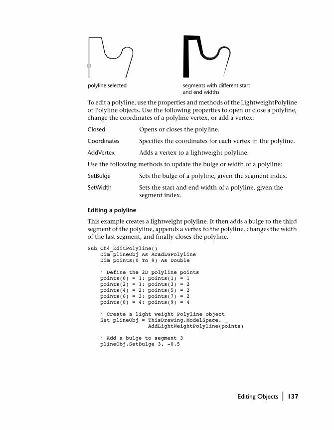
To edit a polyline, use the properties and methods of the LightweightPolyline or Polyline objects. Use the following properties to open or close a polyline, change the coordinates of a polyline vertex, or add a vertex:
Closed Opens or closes the polyline.
Coordinates Specifies the coordinates for each vertex in the polyline.
AddVertex Adds a vertex to a lightweight polyline.
Use the following methods to update the bulge or width of a polyline:
SetBulge Sets the bulge of a polyline, given the segment index.
SetWidth Sets the start and end width of a polyline, given the segment index.
Editing a polyline
This example creates a lightweight polyline. It then adds a bulge to the third segment of the polyline, appends a vertex to the polyline, changes the width of the last segment, and finally closes the polyline.
Sub Ch4_EditPolyline() Dim plineObj As AcadLWPolyline Dim points(0 To 9) As Double ’ Define the 2D polyline points points(0) = 1: points(1) = 1 points(2) = 1: points(3) = 2 points(4) = 2: points(5) = 2 points(6) = 3: points(7) = 2 points(8) = 4: points(9) = 4 ’ Create a light weight Polyline object Set plineObj = ThisDrawing.ModelSpace. _ AddLightWeightPolyline(points) ’ Add a bulge to segment 3 plineObj.SetBulge 3, -0.5
polyline selected segments with different start and end widths
Editing Objects | 137
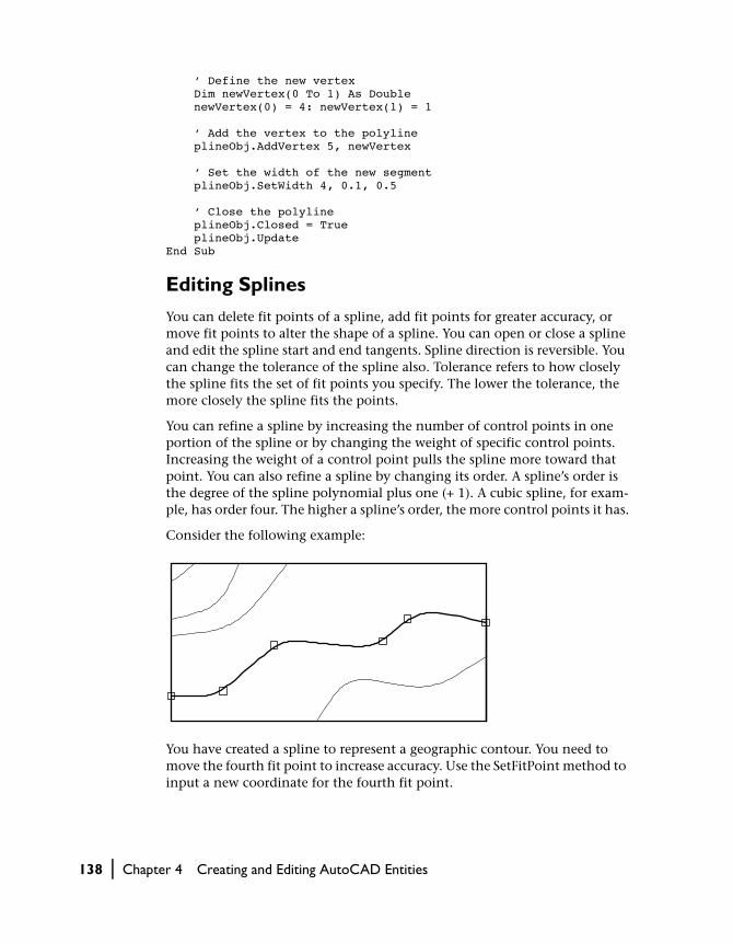
’ Define the new vertex Dim newVertex(0 To 1) As Double newVertex(0) = 4: newVertex(1) = 1 ’ Add the vertex to the polyline plineObj.AddVertex 5, newVertex ’ Set the width of the new segment plineObj.SetWidth 4, 0.1, 0.5 ’ Close the polyline plineObj.Closed = True plineObj.UpdateEnd Sub
Editing Splines
You can delete fit points of a spline, add fit points for greater accuracy, or move fit points to alter the shape of a spline. You can open or close a spline and edit the spline start and end tangents. Spline direction is reversible. You can change the tolerance of the spline also. Tolerance refers to how closely the spline fits the set of fit points you specify. The lower the tolerance, the more closely the spline fits the points.
You can refine a spline by increasing the number of control points in one portion of the spline or by changing the weight of specific control points. Increasing the weight of a control point pulls the spline more toward that point. You can also refine a spline by changing its order. A spline’s order is the degree of the spline polynomial plus one (+ 1). A cubic spline, for exam-ple, has order four. The higher a spline’s order, the more control points it has.
Consider the following example:
You have created a spline to represent a geographic contour. You need to move the fourth fit point to increase accuracy. Use the SetFitPoint method to input a new coordinate for the fourth fit point.
138 | Chapter 4 Creating and Editing AutoCAD Entities

Use the following editable properties to change splines:
Closed Opens or closes the spline.
ControlPoints Specifies the control points of a spline.
EndTangent Specifies the end tangent of the spline as a directional vector.
FitPoints Specifies all the fit points of a spline.
FitTolerance Refits the spline to the existing points with new tolerance values.
Knots Specifies the knots vector for the spline.
StartTangent Specifies the start tangent for the spline.
In addition, you can use the following methods to edit splines:
AddFitPoint Adds a single fit point to the spline at a given index.
DeleteFitPoint Deletes the fit point of a spline at a given index.
ElevateOrder Elevates the order of the spline to the given order.
GetFitPoint Gets the fit point of the spline at a given index. (Gets one fit point only. To query all the fit points of the spline, use the FitPoints property.)
Reverse Reverses the direction of a spline.
SetControlPoint
Sets the control point of the spline at a given index.
SetFitPoint Sets the fit point of the spline at a given index. (Sets one fit point only. To change all the fit points of the spline, use the FitPoints property.)
SetWeight Sets the weight of the control point at a given index.
fourth fit point — original location
fourth fit point — new location
result
Editing Objects | 139

Use the following read-only properties to query splines:
Degree Gets the degree of the spline’s polynomial representation.
Area Gets the enclosed area of a spline.
IsPeriodic Specifies if the given spline is periodic.
IsPlanar Specifies if the given spline is planar.
IsRational Specifies if the given spline is rational.
NumberOfControlPoints
Gets the number of control points of the spline.
NumberOfFitPoints
Gets the number of fit points of the spline.
Changing a control point on a spline
This example creates a spline and then changes the first control point for the spline.
Sub Ch4_ChangeSplineControlPoint() ’ Create the spline Dim splineObj As AcadSpline Dim noOfPoints As Integer Dim startTan(0 To 2) As Double Dim endTan(0 To 2) As Double Dim fitPoints(0 To 8) As Double noOfPoints = 3 startTan(0) = 0.5: startTan(1) = 0.5: startTan(2) = 0 endTan(0) = 0.5: endTan(1) = 0.5: endTan(2) = 0 fitPoints(0) = 1: fitPoints(1) = 1: fitPoints(2) = 0 fitPoints(3) = 5: fitPoints(4) = 5: fitPoints(5) = 0 fitPoints(6) = 10: fitPoints(7) = 0: fitPoints(8) = 0 Set splineObj = ThisDrawing.ModelSpace. _ AddSpline(fitPoints, startTan, endTan) splineObj.Update ’ Change the coordinate of the first fit point Dim controlPoint(0 To 2) As Double controlPoint(0) = 0 controlPoint(1) = 3 controlPoint(2) = 0 splineObj.SetControlPoint 0, controlPoint splineObj.UpdateEnd Sub
140 | Chapter 4 Creating and Editing AutoCAD Entities

Editing Hatches
You can edit both hatch boundaries and hatch patterns. If you edit the boundary of an associative hatch, the pattern is updated as long as the edit-ing results in a valid boundary. Associative hatches are updated even if they’re on layers that are turned off. You can modify hatch patterns or choose a new pattern for an existing hatch, but associativity can only be set when a hatch is created. You can check to see if a Hatch object is associative by using the AssociativeHatch property. (See the AddHatch method for more informa-tion on creating a hatch.)
You must re-evaluate a hatch using the Evaluate method to see any edits to the hatch.
Editing Hatch BoundariesYou can append or insert loops into the hatch boundaries. Associative hatches are updated to match any changes made to their boundaries. Non-associative hatches are not updated.
To edit a hatch boundary, use one of the following methods:
AppendInnerLoop
Appends an inner loop to the hatch.
AppendOuterLoop
Appends an outer loop to the hatch.
InsertLoopAt Inserts a loop at a given index of a hatch.
Appending an inner loop to a hatch
This example creates an associative hatch. It then creates a circle and appends the circle as an inner loop to the hatch.
Sub Ch4_AppendInnerLoopToHatch() Dim hatchObj As AcadHatch Dim patternName As String Dim PatternType As Long Dim bAssociativity As Boolean ’ Define and create the hatch patternName = "ANSI31" PatternType = 0 bAssociativity = True Set hatchObj = ThisDrawing.ModelSpace. _ AddHatch(PatternType, patternName, bAssociativity)
Editing Objects | 141

’ Create the outer loop for the hatch. Dim outerLoop(0 To 1) As AcadEntity Dim center(0 To 2) As Double Dim radius As Double Dim startAngle As Double Dim endAngle As Double center(0) = 5: center(1) = 3: center(2) = 0 radius = 3 startAngle = 0 endAngle = 3.141592 Set outerLoop(0) = ThisDrawing.ModelSpace. _ AddArc(center, radius, startAngle, endAngle) Set outerLoop(1) = ThisDrawing.ModelSpace. _ AddLine(outerLoop(0).startPoint, outerLoop(0).endPoint) ’ Append the outer loop to the hatch object hatchObj.AppendOuterLoop (outerLoop) ’ Create a circle as the inner loop for the hatch. Dim innerLoop(0) As AcadEntity center(0) = 5: center(1) = 4.5: center(2) = 0 radius = 1 Set innerLoop(0) = ThisDrawing.ModelSpace. _ AddCircle(center, radius) ’ Append the circle as an inner loop to the hatch hatchObj.AppendInnerLoop (innerLoop) ’ Evaluate and display the hatch hatchObj.Evaluate ThisDrawing.Regen TrueEnd Sub
Editing Hatch PatternsYou can change the angle or spacing of an existing hatch pattern or replace it with a solid-fill or one of the predefined patterns that AutoCAD offers. The Pattern option in the Boundary Hatch dialog box displays a list of these pat-terns. To reduce file size, the hatch is defined in the drawing as a single graphic object.
The following example demonstrates the result of changing the hatch angle by 90 degrees.
line hatch pattern before editing
line hatch pattern after editing
142 | Chapter 4 Creating and Editing AutoCAD Entities

Use the following properties and methods to edit the hatch patterns:
PatternAngle Specifies the angle of the hatch pattern.
PatternDouble Specifies if the user-defined hatch is double-hatched.
PatternName Specifies the hatch pattern name (does not change the pattern type).
PatternScale Specifies the hatch pattern scale.
PatternSpace Specifies the user-defined hatch pattern spacing.
SetPattern Sets the pattern name and pattern type for the hatch.
Changing the pattern spacing of a hatch
This example creates a hatch. It then adds two to the current pattern spacing for the hatch.
Sub Ch4_ChangeHatchPatternSpace() Dim hatchObj As AcadHatch Dim patternName As String Dim PatternType As Long Dim bAssociativity As Boolean ’ Define the hatch patternName = "ANSI31" PatternType = 0 bAssociativity = True ’ Create the associative Hatch object Set hatchObj = ThisDrawing.ModelSpace. _ AddHatch(PatternType, patternName, bAssociativity) ’ Create the outer loop for the hatch. Dim outerLoop(0 To 0) As AcadEntity Dim center(0 To 2) As Double Dim radius As Double center(0) = 5 center(1) = 3 center(2) = 0 radius = 3 Set outerLoop(0) = ThisDrawing.ModelSpace. _ AddCircle(center, radius) hatchObj.AppendOuterLoop (outerLoop) hatchObj.Evaluate ’ Change the spacing of the hatch pattern by ’ adding 2 to the current spacing hatchObj.patternSpace = hatchObj.patternSpace + 2 hatchObj.Evaluate ThisDrawing.Regen TrueEnd Sub
Editing Objects | 143

Using Layers, Colors, and Linetypes
Layers are like transparent overlays on which you organize and group differ-ent kinds of drawing information. The objects you create have properties including layers, colors, and linetypes. Color helps you distinguish similar elements in your drawings, and linetypes help you differentiate easily between different drafting elements, such as centerlines or hidden lines. Organizing layers and objects on layers makes it easier to manage the infor-mation in your drawings.
Working with Layers
You are always drawing on a layer. It may be the default layer or a layer you create and name yourself. Each layer has an associated color and linetype. For example, you can create a layer on which you draw only centerlines and assign the color blue and the linetype CENTER to that layer. Then, whenever you want to draw centerlines you can switch to that layer and start drawing. You don’t need to set up your linetype and color every time you want to draw a centerline. Also, if you don’t want to display or plot the centerlines, you can turn off that layer. Using layers is one major advantage to creating drawings with AutoCAD instead of with paper and pencil.
In paper space, or when working in a floating viewport, you can specify layer visibility individually for each viewport. The same drawing limits, coordinate system, and zoom factor apply to all layers in a drawing. If you consistently use a specific layering scheme, you can set up a template drawing with layers, linetypes, and colors already assigned.
walls
electrical
furniture
all layers
144 | Chapter 4 Creating and Editing AutoCAD Entities

Sorting Layers and LinetypesAll layers and linetypes are kept within their parent Collection objects. Layers are kept within the Layers collection, and linetypes are kept within the Linetypes collection.
You can iterate through these collections to find all the layers and linetypes in a drawing.
Iterating through the Layers collection
The following code iterates through the Layers collection to gather the names of all the layers in the drawing. The names are then displayed in a message box.
Sub Ch4_IteratingLayers() Dim layerNames As String Dim entry As AcadLayer layerNames = "" For Each entry In ThisDrawing.Layers layerNames = layerNames + entry.Name + vbCrLf Next MsgBox "The layers in this drawing are: " + _ vbCrLf + layerNamesEnd Sub
Creating and Naming LayersYou can create and name a layer for each conceptual grouping (such as walls or dimensions) and assign colors and linetypes to those layers. When orga-nizing your layer scheme, choose layer names carefully.
When you begin a new drawing, AutoCAD creates a special layer named 0. By default, layer 0 is assigned the color number 7 (white or black depending on your background color) and the CONTINUOUS linetype. Layer 0 cannot be deleted.
You can create new layers and assign color and linetype properties to those layers. Each individual layer is part of the Layers collection. Use the Add method to create a new layer and add it to the Layers collection.
You can assign a name to a layer when it is created. To change the name of a layer after it has been created, use the Name property. Layer names can include up to thirty-one characters and contain letters, digits, and the special characters dollar sign ($), hyphen (-), and underscore (_) but cannot include blank spaces.
Using Layers, Colors, and Linetypes | 145
Assigning an object to a new layer
The following code creates a circle and a new layer. The new layer is assigned the color red. The circle is assigned to the layer, and the color of the circle changes accordingly.
Sub Ch4_NewLayer() ’ Create a circle Dim circleObj As AcadCircle Dim center(0 To 2) As Double Dim radius As Double center(0) = 2: center(1) = 2: center(2) = 0 radius = 1 Set circleObj = ThisDrawing.ModelSpace. _ AddCircle(center, radius) ’ Assign the circle the color "ByLayer" so ’ that the circle will automatically pick ’ up the color of the layer on which it resides circleObj.Color = acByLayer ’ Create a new layer called "ABC" Dim layerObj As AcadLayer Set layerObj = ThisDrawing.Layers.Add("ABC") ’ Assign the "ABC" layer the color red layerObj.Color = acRed ’ Assign the circle to the "ABC" layer circleObj.Layer = "ABC" circleObj.UpdateEnd Sub
Making a Layer ActiveYou are always drawing on the active layer. When you make a layer active, you can create new objects on that layer. If you make a different layer active, any new objects you create are created on that new active layer and use its color and linetype. You cannot make a layer active if it is frozen.
To make a layer active, use the ActiveLayer property. This property is set on the current drawing. For example
Dim newlayer As AcadLayerSet newlayer = ThisDrawing.Layers.Add("LAYER1")ThisDrawing.ActiveLayer = newlayer
146 | Chapter 4 Creating and Editing AutoCAD Entities

Controlling Layer VisibilityAutoCAD does not display or plot the objects drawn on invisible layers. If you need an unobstructed view when working in detail on a particular layer or set of layers, or if you don’t want to plot certain details such as construc-tion or reference lines, you can turn off layers or freeze layers.
The method you choose to control a layer’s visibility depends on how you work and the size of your drawing. You can freeze layers you want to be invis-ible for long periods.
You can only plot layers that are on and thawed. On most plotters, you can assign a different pen to each color number in the drawing. On single-pen plotters, AutoCAD pauses for pen changes.
Turning Layers On and OffTurned-off layers are regenerated with the drawing but are not displayed or plotted. You can turn layers off rather than freeze them if you are switching frequently between visible and invisible layers. By turning layers off, you avoid regenerating the drawing every time you thaw a layer. When you turn a layer on that has been turned off, AutoCAD redraws the objects on that layer.
To turn layers on and off, use the LayerOn property. If you input a value of TRUE to this property, the layer is turned on. If you input a value of FALSE, the layer is turned off.
Turning off a layer
This example creates a new layer, adds a circle to the layer, then turns off the layer so that the circle is no longer visible.
Sub Ch4_LayerInvisble() ’ Create a circle Dim circleObj As AcadCircle Dim center(0 To 2) As Double Dim radius As Double center(0) = 2: center(1) = 2: center(2) = 0 radius = 1 Set circleObj = ThisDrawing.ModelSpace. _ AddCircle(center, radius)
all layers on two layers on one layer on
Using Layers, Colors, and Linetypes | 147

circleObj.Color = acByLayer ’ Create a new layer called "ABC" Dim layerObj As AcadLayer Set layerObj = ThisDrawing.Layers.Add("ABC") layerObj.Color = acRed ’ Assign the circle to the "ABC" layer circleObj.Layer = "ABC" circleObj.Update ’ Turn off layer "ABC" layerObj.LayerOn = False ThisDrawing.Regen acActiveViewportEnd Sub
Freezing and Thawing LayersYou can freeze layers to speed up display changes, improve object selection performance, and reduce regeneration time for complex drawings. AutoCAD does not display, plot, or regenerate objects on frozen layers. Freeze layers that you want to be invisible for long periods. When you “thaw” a frozen layer, AutoCAD regenerates and displays the objects on that layer.
To freeze or thaw a layer, use the Freeze property. If you input a value of TRUE to this property, the layer is frozen. If you input a value of FALSE, the layer is thawed.
Freezing a layer
This example creates a new layer called “ABC” and then freezes the layer.
Sub Ch4_LayerFreeze() ’ Create a new layer called "ABC" Dim layerObj As AcadLayer Set layerObj = ThisDrawing.Layers.Add("ABC") ’ Freeze layer "ABC" layerObj.Freeze = TrueEnd Sub
Locking and Unlocking LayersLocking layers is useful when you want to edit objects associated with partic-ular layers but also want to view objects on other layers. You cannot edit the objects on a locked layer; however, they are still visible if the layer is on and thawed. You can make a locked layer current and you can add objects to it. You can freeze and turn off locked layers and change their associated colors and linetypes.
148 | Chapter 4 Creating and Editing AutoCAD Entities

To lock or unlock a layer, use the Lock property. If you input a value of TRUE to this property, the layer is locked. If you input a value of FALSE, the layer is unlocked.
Locking a layer
This example creates a new layer called “ABC” and then locks the layer.
Sub Ch4_LayerLock() ’ Create a new layer called "ABC" Dim layerObj As AcadLayer Set layerObj = ThisDrawing.Layers.Add("ABC") ’ Lock layer "ABC" layerObj.Lock = TrueEnd Sub
Assigning Color to a LayerYou can assign color to a layer. When specifying a color, you can enter the name of the color or its AutoCAD Color Index (ACI) number. Standard color names are available only for colors 1 to 7.
By default, AutoCAD assigns color number 7 (white or black, depending on your drawing background) to newly created layers. You can assign an object a color that is different from the layer color.
To assign color to a layer, use the Color property.
Colors can be set and read as numeric index values ranging from 0 to 256. Constants have been provided for the standard seven colors, and BYBLOCK and BYLAYER designations.
If you use acByBlock, AutoCAD draws new objects in the default color (white or black, depending on your configuration) until they are grouped into the block. When the block is inserted in the drawing, the objects in the block inherit the current setting of the Color property.
If you use acByLayer, new objects assume the color of the layer upon which they are drawn.
Assigning a Linetype to a LayerWhen you're defining layers, linetypes provide another way to convey visual information. A linetype is a repeating pattern of dashes, dots, and blank spaces you can use to distinguish the purpose of one line from another.
Using Layers, Colors, and Linetypes | 149

The linetype name and definition describe the particular dash-dot sequence, the relative lengths of dashes and blank spaces, and the characteristics of any included text or shapes.
To assign a linetype to a layer, use the Linetype property. This property takes the name of the linetype as input.
Deleting LayersTo delete a layer, use the Delete method.
You can delete a layer at any time during a drawing session. You cannot delete the current layer, layer 0, an xref-dependent layer, or a layer that con-tains objects.
NOTE Layers referenced by block definitions, along with the special layer named DEFPOINTS, cannot be deleted even if they do not contain visible objects.
Working with Colors
You can assign colors to layers and to individual objects in a drawing. Each color is identified by a name or an AutoCAD Color Index (ACI) number, an integer from 1 through 255. Any number of objects and layers can have the same color number. You can assign each color number to a different pen on a pen plotter or use the color numbers to identify certain objects in the draw-ing, even though you can’t see the colors on your screen.
Specifying ColorsWhen specifying a color, you can enter the name of the color or its ACI num-ber. The ACI provides 255 color numbers. Standard color names are available only for colors 1 to 7.
Colors 1 to 7
Color number Color name
1 Red
2 Yellow
3 Green
4 Cyan
150 | Chapter 4 Creating and Editing AutoCAD Entities
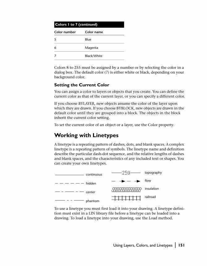
Colors 8 to 255 must be assigned by a number or by selecting the color in a dialog box. The default color (7) is either white or black, depending on your background color.
Setting the Current ColorYou can assign a color to layers or objects that you create. You can define the current color as that of the current layer, or you can specify a different color.
If you choose BYLAYER, new objects assume the color of the layer upon which they are drawn. If you choose BYBLOCK, new objects are drawn in the default color until they are grouped into a block. The objects in the block inherit the current color setting.
To set the current color of an object or a layer, use the Color property.
Working with Linetypes
A linetype is a repeating pattern of dashes, dots, and blank spaces. A complex linetype is a repeating pattern of symbols. The linetype name and definition describe the particular dash-dot sequence, and the relative lengths of dashes and blank spaces, and the characteristics of any included text or shapes. You can create your own linetypes.
To use a linetype you must first load it into your drawing. A linetype defini-tion must exist in a LIN library file before a linetype can be loaded into a drawing. To load a linetype into your drawing, use the Load method.
5 Blue
6 Magenta
7 Black/White
Colors 1 to 7 (continued)
Color number Color name
continuous
hidden
center
phantom
topography
flow
insulation
railroad
Using Layers, Colors, and Linetypes | 151

Loading a linetype into AutoCAD
This example attempts to load the linetype “CENTER” from the acad.lin file. If the linetype already exists, or the file does not exist, then a message is displayed.
Sub Ch4_LoadLinetype() On Error GoTo ERRORHANDLER Dim linetypeName As String linetypeName = "CENTER" ’ Load "CENTER" line type from acad.lin file ThisDrawing.Linetypes.Load linetypeName, "acad.lin" Exit Sub ERRORHANDLER: MsgBox Err.Description End Sub
NOTE The linetypes used internally by AutoCAD should not be confused with the hardware linetypes provided by some plotters. The two types of dashed lines produce similar results. Do not use both types at the same time, however, because the results can be unpredictable.
Making a Linetype ActiveTo use a linetype to draw on the current layer, you must make it active. All newly created objects are drawn using the active linetype.
NOTE Xref-dependent linetypes cannot be made active.
If you choose BYLAYER, new objects assume the linetype properties of the active linetype. If you choose BYBLOCK, new objects are drawn using that linetype until they are grouped into a block. The objects in the block inherit the current linetype properties.
To make a linetype active, use the ActiveLinetype property. This property is set on the current drawing. For example
ThisDrawing.ActiveLinetype = ThisDrawing. _Linetypes.Item("CONTINUOUS")
Renaming LinetypesYou may want to rename a linetype to better identify how it’s used. You can rename a linetype at any time during the drawing session.
152 | Chapter 4 Creating and Editing AutoCAD Entities

When you rename a linetype, you are renaming only the linetype definition in your drawing. The name in the LIN library file is not being updated to reflect the new name.
To rename a linetype, use the Name property.
NOTE You cannot rename linetypes BYLAYER, BYBLOCK, or CONTINUOUS or xref-dependent linetypes.
Deleting LinetypesYou can delete a linetype at any time during a drawing session; however, line-types that cannot be deleted include BYLAYER, BYBLOCK, CONTINUOUS, the current linetype, and xref-dependent linetypes. Also, linetypes referenced by block definitions cannot be deleted, even if they contain no visible objects.
To delete a linetype, use the Delete method.
Changing Linetype DescriptionsLinetypes can have a description associated with them. The description pro-vides an ASCII representation of the linetype. You can assign or change a linetype description by using the Description property.
A linetype description can have up to forty-seven characters. The description can be a comment or a series of underscores, dots, dashes, and spaces to show a simple representation of the linetype pattern. For example
ThisDrawing.ActiveLinetype.Description = "Exterior Wall"
Specifying Linetype ScaleYou can specify the linetype scale for objects you create. The smaller the scale, the more repetitions of the pattern are generated per drawing unit. By default, AutoCAD uses a global linetype scale of 1.0, which is equal to one drawing unit. You can change the linetype scale for all drawing objects, attribute references, and groups.
ltscale = 1 ltscale = 0.7 ltscale = 0.4
Using Layers, Colors, and Linetypes | 153

To change the linetype scale, use the LinetypeScale property.
The CELTSCALE system variable sets the linetype scale for newly created objects. LTSCALE globally changes the linetype scale of existing objects as well as new objects. To change the values of system variables using AutoCAD ActiveX Automation, use the SetVariable method.
Changing the linetype scale for a circle
Sub Ch4_ChangeLinetypeScale() Dim center(0 To 2) As Double Dim radius As Double Dim circleObj As AcadCircle ’ Create a circle object in model space center(0) = 2 center(1) = 2 center(2) = 0 radius = 4 Set circleObj = ThisDrawing.ModelSpace. _ AddCircle(center, radius) ’ Set the linetype scale of a circle to .5 circleObj.LinetypeScale = 0.5 circleObj.UpdateEnd Sub
Assigning Layers, Colors, and Linetypes to Objects
Once you’ve defined layers, colors, and linetypes, you can assign them to objects in your drawing. You can group associated components of a drawing by assigning objects to layers. You can control layer visibility, color, and line-type and specify whether objects on a layer can be edited. You can move objects from one layer to another and change the name of a layer.
The number of layers in a drawing and the number of objects per layer are virtually unlimited. You can assign a name to each layer and select any com-bination of layers for display.
You can define blocks from objects that were originally drawn on different layers with different colors and linetypes. You can preserve the layer, color, and linetype information of objects in a block. Then, each time you insert the block, you have each object drawn on its original layer with its original color and linetype.
154 | Chapter 4 Creating and Editing AutoCAD Entities

Changing an Object’s LayerOnce you have created an object and assigned layer, color, and linetype prop-erties to it, you may wish to change the object’s layer. Changing an object’s layer is useful if you accidentally create an object on the wrong layer or decide to change your layer organization later.
To change an object’s layer, use the Layer property provided for that object. The Layer property takes the name of the layer as input.
Moving an object to a different layer
This example creates a circle on the active layer and then creates a new layer called “ABC”. It then moves the circle to the new layer.
Sub Ch4_MoveObjectNewLayer() ’ Create a circle Dim circleObj As AcadCircle Dim center(0 To 2) As Double Dim radius As Double center(0) = 2: center(1) = 2: center(2) = 0 radius = 1 Set circleObj = ThisDrawing.ModelSpace. _ AddCircle(center, radius) ’ Create a new layer called "ABC" Dim layerObj As AcadLayer Set layerObj = ThisDrawing.Layers.Add("ABC") ’ Assign the circle to the "ABC" layer circleObj.Layer = "ABC" circleObj.UpdateEnd Sub
Changing an Object’s ColorYou can assign colors to individual objects in a drawing. Each color is identi-fied by an ACI number, an integer from 1 to 255. Standard color constants are available only for colors 1 to 7. The color constants are
■ acRed, acYellow, acGreen, acCyan, acBlue, acMagenta, and acWhite
Setting a color for the object overrides the color setting for the layer on which the object resides.
If you want to retain an object on a specific layer but you don't want it to keep the color of that layer, you can change the object's color. To change an object's color, use the Color property provided for that object.
Using Layers, Colors, and Linetypes | 155

Changing the color of a circle
This example creates a circle and then colors the circle red.
Sub Ch4_ColorCircle() ’ Create a circle Dim circleObj As AcadCircle Dim center(0 To 2) As Double Dim radius As Double center(0) = 2: center(1) = 2: center(2) = 0 radius = 1 Set circleObj = ThisDrawing.ModelSpace. _ AddCircle(center, radius) ’ Color the circle red circleObj.Color = acRed circleObj.UpdateEnd Sub
Changing an Object’s LinetypeYou create objects using the current linetype. If the current linetype is set to BYLAYER, you create objects using the linetype assigned to the current layer. The default setting for linetype is BYLAYER.
You can associate linetypes with all AutoCAD objects but they are not dis-played with text, points, viewports, xlines, rays, 3D polylines, and blocks. If a line is too short to hold at least one dash sequence, AutoCAD draws a con-tinuous line between the endpoints.
By default, objects inherit the linetype of the layer on which they are created. To change an object’s linetype, use the Linetype property provided for that object. The Linetype property takes the name of the linetype to assign to the object as input.
Changing the linetype of a circle
This example creates a circle. It then attempts to load the linetype “CENTER” from the acad.lin file. If the linetype already exists, or the file does not exist, then a message is displayed. Finally, it sets the linetype for the circle to be “CENTER.”
156 | Chapter 4 Creating and Editing AutoCAD Entities

Sub Ch4_ChangeCircleLinetype() On Error Resume Next ’ Create a circle Dim circleObj As AcadCircle Dim center(0 To 2) As Double Dim radius As Double center(0) = 2: center(1) = 2: center(2) = 0 radius = 1 Set circleObj = ThisDrawing.ModelSpace. _ AddCircle(center, radius) Dim linetypeName As String linetypeName = "CENTER" ’ Load "CENTER" line type from acad.lin file ThisDrawing.Linetypes.Load linetypeName, "acad.lin" If Err.Description <> "" Then MsgBox Err.Description ’ Assign the circle the linetype "CENTER" circleObj.Linetype = "CENTER" circleObj.UpdateEnd Sub
NOTE Before you can assign a linetype to an object, the linetype must be loaded into the current drawing. To load a linetype into the drawing, use the Load method.
Adding Text to Drawings
Text conveys important information in your drawing. Use text for title blocks, to label parts of the drawing, to give specifications, or to make annotations.
AutoCAD provides various ways to create text. For short, simple entries, use line text. For longer entries with internal formatting, use multiline text (mtext). Although all entered text uses the current text style, which estab-lishes the default font and format settings, you can use several methods to customize the text appearance.
Working with Text Styles
All text in an AutoCAD drawing has a style associated with it. When you enter text, AutoCAD uses the current text style, which sets the font, size,
Adding Text to Drawings | 157

angle, orientation, and other text characteristics. Text style controls the attributes listed in the following table:
You can use or modify the default style or create and load a new style. Once you’ve created a style, you can modify its attributes or delete it when you no longer need it.
Creating and Modifying Text StylesExcept for the default STANDARD style, you must create any text style you want to use. New text inherits height, width factor, obliquing angle, and text generation properties from the current text style. To create a text style, use the Add method to create a new TextStyle object and add it to the TextStyles collection. The Add method takes a TextStyle name as input. Once created, you cannot change the name of a text style through AutoCAD ActiveX Auto-mation.
Style names can contain letters, numbers, and the special characters dollar sign ($), underscore (_), and hyphen (-). AutoCAD converts the characters to uppercase. If you don’t enter a style name, AutoCAD automatically names the style Stylen, where n is a number that starts at 1. Each new style is shown in increments of 1.
You can modify an existing style by changing the properties of the TextStyle object. You can also update existing text of that style type to reflect the changes. Use the following properties to modify a TextStyle object:
Text style properties
Property Default Description
Name STANDARD Name with up to thirty-one characters
Font file txt.shx File associated with a font (character style)
Big Font file none Special shape definition file used for a non-ASCII character set, such as Kanji
Height 0 Character height
Width 1 Expansion or compression of the characters
Oblique angle 0 Slant of the characters
Text generation flag
No, No Backward text, upside-down text, or both
158 | Chapter 4 Creating and Editing AutoCAD Entities

FontFile Specifies the file associated with a font (character style).
BigFontFile Specifies the special shape definition file used for a non-ASCII character set, such as Kanji.
Height Specifies the character height.
Width Specifies the expansion or compression of the characters.
ObliqueAngle Specifies the slant of the characters.
TextGenerationFlag
Specifies backward text, upside-down text, or both.
If you change an existing style’s font or orientation, all text using that style is changed to use the new font or orientation. Changing text height, width factor, and oblique angle does not change existing text but does change sub-sequently created text objects.
NOTE You must call the Regen or Update methods to see any changes to the above properties.
Assigning FontsFonts define the shapes of the text characters that make up each character set. A single font can be used by more than one style. If your company has a standard font type, you can modify other style settings to create a set of styles that uses a standard font in different ways. The following illustration shows the same font used by different styles that have different obliquing settings to define the slant of the text:
Adding Text to Drawings | 159
You can assign a font to a text style using the FontFile property of the TextStyle object. By entering the font file containing an AutoCAD-compiled SHX font, you assign that font to the text style.
Setting text fonts
This example gets the current font values for the active text style and then changes the typeface for the font to “PlayBill.” The new font is then set using the SetFont method.
Sub Ch4_UpdateTextFont() Dim typeFace As String Dim Bold As Boolean Dim Italic As Boolean Dim charSet As Long Dim PitchandFamily As Long ’ Get the current settings to fill in the ’ default values for the SetFont method ThisDrawing.ActiveTextStyle.GetFont typeFace, _ Bold, Italic, charSet, PitchandFamily ’ Change the typeface for the font typeFace = "PlayBill" ThisDrawing.ActiveTextStyle.SetFont typeFace, _ Bold, Italic, charSet, PitchandFamily ThisDrawing.Regen acActiveViewportEnd Sub
Using TrueType FontsTrueType® fonts always appear filled in your drawing, however, when you plot, the TEXTFILL system variable controls whether the fonts are filled. By default TEXTFILL is set to 1 to plot the filled-in fonts. When you export the drawing to PostScript® format with the Export method and print it on a PostScript device, the font is plotted as designed.
To increase the speed and performance of TrueType fonts in this release of AutoCAD, the Windows operating system draws some TrueType text directly. Due to limitations in Windows, however, AutoCAD must draw TrueType text that is transformed in certain ways; for instance, text that is mirrored, upside-down, backward, oblique, has a width factor not equal to 1, or is in an orientation that is not coplanar with the screen. A general rule is that TrueType text that looks in AutoCAD as it does in a word processor is drawn by the Windows system; otherwise the TrueType text is drawn by AutoCAD. Text that has been transformed might appear slightly bolder in some circum-stances, especially at lower resolutions. This difference is only in the display of the font and does not affect the plotted output.
160 | Chapter 4 Creating and Editing AutoCAD Entities

Using Unicode and Big FontsAutoCAD now supports the Unicode character-encoding standard. A Unicode font can contain 65,535 characters, with shapes for many lan-guages. Unicode fonts contain many more characters than are defined in your system; therefore, to use a character not available directly from the key-board, you can enter the escape sequence \U+nnnn, where nnnn represents the Unicode hexadecimal value for the character. All AutoCAD SHX shape fonts are now Unicode fonts.
The SHX fonts used in releases prior to Release 13 do not support the \U+nnnn sequence. However, you can continue to generate accented charac-ters by using characters in the 128 to 256 range.
The text files for some alphabets, such as kanji, contain thousands of non-ASCII characters. To accommodate such text, AutoCAD supports a special type of shape definition known as a Big Font file. You can set a style to use both regular and Big Font files.
For samples of the standard fonts supplied with AutoCAD, see appendix E, “Standard Libraries” in the AutoCAD Command Reference. AutoCAD also pro-vides ways to substitute one font for another or to specify a default font. For more information see “Substituting Fonts” on page 176.
Specify normal fonts using the FontFile property. Specify Big Fonts using the BigFontFile property.
Changing font files
This example changes the FontFile and BigFontFile properties. You need to replace the path information listed in this example with path and file names appropriate for your system.
Sub Ch4_ChangeFontFiles() ThisDrawing.ActiveTextStyle.BigFontFile = _ "C:/AutoCAD/Fonts/bigfont.shx" ThisDrawing.ActiveTextStyle.fontFile = _ "C:/AutoCAD/Fonts/italic.shx"End Sub
NOTE Long file names that contain commas are not accepted as font file names.
Adding Text to Drawings | 161

Setting Text HeightText height determines the size in drawing units of the letters in the font you are using. The value usually represents the size of the uppercase letters, with the exception of TrueType fonts.
For TrueType fonts, the value specified for text height might not represent the height of uppercase letters. The height specified represents the height of a capital letter plus an accent area reserved for accent marks and other marks used in non-English languages. The relative portion of areas assigned to cap-ital letters and accent characters is determined by the font designer at the time the font is designed, and, consequently, will vary from font to font.
In addition to the height of a capital letter and the ascent area that make up the height specified by the user, TrueType fonts have a descent area for por-tions of characters that extend below the text insertion line. Examples of such characters are y, j, p, g, and q.
You specify the text height using the Height property. This property accepts positive numbers only.
Changing the height of a Text object
This example creates a line of text and then changes the height of the text.
Sub Ch4_ChangeTextHeight() Dim textObj As AcadText Dim textString As String Dim insertionPoint(0 To 2) As Double Dim height As Double ’ Define the text object textString = "Hello, World." insertionPoint(0) = 3 insertionPoint(1) = 3 insertionPoint(2) = 0 height = 0.5 ’ Create the text object in model space Set textObj = ThisDrawing.ModelSpace. _ AddText(textString, insertionPoint, height) ’ Change the value of the Height to 1 textObj.height = 1 textObj.UpdateEnd Sub
162 | Chapter 4 Creating and Editing AutoCAD Entities

Setting Obliquing AngleThe obliquing angle determines the forward or backward slant of the text. The angle represents the offset from its vertical axis (90 degrees).
To set the obliquing angle, use the ObliqueAngle property. The obliquing angle must be provided in radians. A positive angle denotes a lean to the right, a negative value will have 2*PI added to it to convert it to its positive equivalent.
Creating oblique text
This example creates a Text object then slants the text 45 degrees.
Sub Ch4_ObliqueText() Dim textObj As AcadText Dim textString As String Dim insertionPoint(0 To 2) As Double Dim height As Double ’ Define the text object textString = "Hello, World." insertionPoint(0) = 3 insertionPoint(1) = 3 insertionPoint(2) = 0 height = 0.5 ’ Create the text object in model space Set textObj = ThisDrawing.ModelSpace. _ AddText(textString, insertionPoint, height) ’ Change the value of the ObliqueAngle ’ to 45 degrees (.707 radians) textObj.ObliqueAngle = 0.707 textObj.UpdateEnd Sub
-30deg rotation-30deg obliquing
30deg rotation-30deg obliquing 30deg rotation
30deg obliquing
0deg rotation0deg obliquing
Adding Text to Drawings | 163

Setting Text Generation FlagThe text generation flag specifies if the text is displayed backward or upside-down.
To set the text generation flag, use the TextGenerationFlag property. To make the text display backward, enter acTextFlagBackward for this property. To make the text display upside-down, enter acTextFlagUpsideDown for this property. To make the text display both backward and upside-down, add the two constants together by entering acTextFlagBackward+acTextFlagUpsidedown for this property.
Displaying text backward
This example creates a line of text, then sets it to display backward using the TextGenerationFlag property.
Sub Ch4_ChangingTextGenerationFlag() Dim textObj As AcadText Dim textString As String Dim insertionPoint(0 To 2) As Double Dim height As Double ’ Create the text object textString = "Hello, World." insertionPoint(0) = 3 insertionPoint(1) = 3 insertionPoint(2) = 0 height = 0.5 Set textObj = ThisDrawing.ModelSpace. _ AddText(textString, insertionPoint, height) ’ Change the value of the TextGenerationFlag textObj.TextGenerationFlag = acTextFlagBackward textObj.UpdateEnd Sub
Using Line Text (Text)
The text you add to your drawings conveys a variety of information. It may be a complex specification, title block information, a label, or even part of the drawing. For shorter entries that do not require multiple fonts or lines, create line text using the Text object. Line text is more convenient for labels.
164 | Chapter 4 Creating and Editing AutoCAD Entities
Creating line textEach individual line of text is a distinct object when using line text. To create a line text object, use the AddText method. This method requires three values as input: the text string, the insertion point, and the height of the text.
The text string is the actual text to be displayed. Unicode, control code, and special characters are accepted. The insertion point is a variant array contain-ing three doubles representing the 3D WCS coordinate in the drawing to place the text. The height of the text is a positive number representing the height of the uppercase text. Height is measured in the current units.
Creating Line Text
This example creates a line of text in model space, at the coordinate (2, 2, 0).
Sub Ch4_CreateText() Dim textObj As AcadText Dim textString As String Dim insertionPoint(0 To 2) As Double Dim height As Double ’ Create the text object textString = "Hello, World." insertionPoint(0) = 2 insertionPoint(1) = 2 insertionPoint(2) = 0 height = 0.5 Set textObj = ThisDrawing.ModelSpace. _ AddText(textString, insertionPoint, height) textObj.UpdateEnd Sub
Adding Text to Drawings | 165

Formatting Line TextA Text object is created using the active text style. You can change the for-matting of the Text object by changing the text style associated with it, or by editing the properties of the Text object. You cannot apply formats to indi-vidual words and characters.
To change a text style associated with an individual Text object, set the StyleName property to a new text style. Once you have changed the text style, use the Update method for the Text object to see the changes in your drawing.
In addition to the standard editable properties for entities (color, layer, line-type, and so forth), other properties that you can change on a Text object include the following:
Alignment Specifies the horizontal and vertical alignment for the text.
InsertionPoint Specifies the insertion point for the text.
ObliqueAngle Specifies the oblique angle of the individual text object.
Rotation Specifies the rotation angle in radians for the text.
ScaleFactor Specifies the scale factor for the text.
TextAlignmentPoint
Specifies the alignment point for the text.
TextGenerationFlag
Specifies whether the text is displayed backward, upside-down, or both simultaneously.
TextString Specifies the actual text string displayed.
Once you have changed a property, use the Update method to see the changes in your drawing.
NOTE For a complete list of methods and properties, see the Text object doc-umentation in the AutoCAD ActiveX and VBA Reference.
Aligning Line TextYou can justify line text with one of the horizontal and vertical alignment options shown in the following illustration. Left alignment is the default. To set the horizontal and vertical alignment options, use the Alignment property.
166 | Chapter 4 Creating and Editing AutoCAD Entities
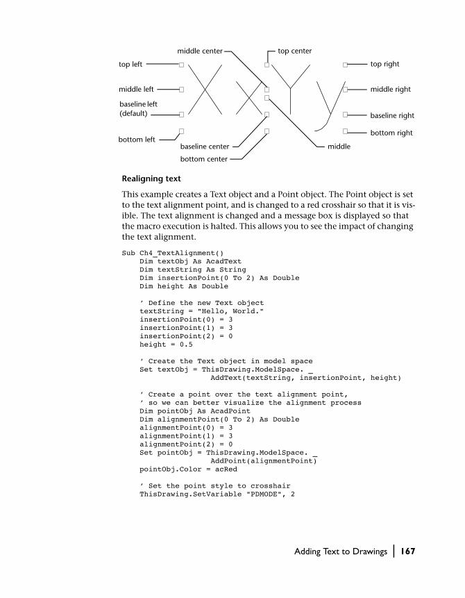
Realigning text
This example creates a Text object and a Point object. The Point object is set to the text alignment point, and is changed to a red crosshair so that it is vis-ible. The text alignment is changed and a message box is displayed so that the macro execution is halted. This allows you to see the impact of changing the text alignment.
Sub Ch4_TextAlignment() Dim textObj As AcadText Dim textString As String Dim insertionPoint(0 To 2) As Double Dim height As Double ’ Define the new Text object textString = "Hello, World." insertionPoint(0) = 3 insertionPoint(1) = 3 insertionPoint(2) = 0 height = 0.5 ’ Create the Text object in model space Set textObj = ThisDrawing.ModelSpace. _ AddText(textString, insertionPoint, height) ’ Create a point over the text alignment point, ’ so we can better visualize the alignment process Dim pointObj As AcadPoint Dim alignmentPoint(0 To 2) As Double alignmentPoint(0) = 3 alignmentPoint(1) = 3 alignmentPoint(2) = 0 Set pointObj = ThisDrawing.ModelSpace. _ AddPoint(alignmentPoint) pointObj.Color = acRed ’ Set the point style to crosshair ThisDrawing.SetVariable "PDMODE", 2
top left
middle left
baseline left (default)
middlebottom left
baseline center
bottom center
middle center top center
top right
middle right
baseline right
bottom right
Adding Text to Drawings | 167

’ Align the text to the Left textObj.Alignment = acAlignmentLeft ThisDrawing.Regen acActiveViewport MsgBox "The Text object is now aligned left" ’ Align the text to the Center textObj.Alignment = acAlignmentCenter ’ Align the text to the point (necessary for ’ all but left aligned text.) textObj.TextAlignmentPoint = alignmentPoint ThisDrawing.Regen acActiveViewport MsgBox "The Text object is now centered" ’ Align the text to the Right textObj.Alignment = acAlignmentRight ThisDrawing.Regen acActiveViewport MsgBox "The Text object is now aligned right" End Sub
Changing Line TextLike any other object, Text objects can be moved, rotated, erased, and copied. You also can mirror text. If you do not want the text to be reversed when you mirror it, you can set the MIRRTEXT system variable to 0.
The following list represents a few of the methods a Text object has for use in editing. For a complete list, see the Text object documentation in the AutoCAD ActiveX and VBA Reference.
ArrayPolar Creates a polar array.
ArrayRectangular
Creates a rectangular.
Copy Copies the Text object.
Erase Erases the Text object.
Mirror Mirrors the Text object.
Move Moves the Text object.
Rotate Rotates the Text object.
168 | Chapter 4 Creating and Editing AutoCAD Entities

Using Multiline Text (Mtext)
For long, complex entries, create multiline text (mtext). Multiline text fits a specified width but can extend vertically to an indefinite length. You can for-mat individual words or characters within the mtext.
Multiline text consists of any number of text lines or paragraphs that fit within a width you specify. Regardless of the number of lines, each set of paragraphs created in a single editing session forms a single object, which you can move, rotate, erase, copy, mirror, stretch, or scale.
Multiline text has more editing options than line text. For example, you can apply underlining, fonts, color, and text height changes to individual char-acters, words, or phrases within a paragraph.
Creating multiline textYou can create a multiline text object (MText object) by using the AddMText method. This method requires three values as input: the text string, the insertion point in the drawing to place the text, and the width of the text bounding box.
The text string is the actual text to be displayed. Unicode, control code, and special characters are accepted. The insertion point is a variant array contain-ing three doubles representing the 3D WCS coordinate in the drawing to place the text. The width of the text is a positive number representing the width of the bounding box for the text. Width is measured in the current units.
Once the MText object is created, you can apply the text height, justification, rotation angle, and style to the MText object, or apply character formatting to selected characters. Justification determines where the text is inserted with respect to the text boundaries.
The height of the MText object you create depends on the number of char-acters in the text string.
left justified right justified middle justified
Adding Text to Drawings | 169

Creating Multiline Text
The following code creates an MText object in model space, at the coordinate (2, 2, 0).
Sub Ch4_CreateMText() Dim mtextObj As AcadMText Dim insertPoint(0 To 2) As Double Dim width As Double Dim textString As String insertPoint(0) = 2 insertPoint(1) = 2 insertPoint(2) = 0 width = 4 textString = "This is a text string for the mtext object." ’ Create a text Object in model space Set mtextObj = ThisDrawing.ModelSpace. _ AddMText(insertPoint, width, textString) ZoomAllEnd Sub
Formatting Multiline TextNew text automatically assumes the characteristics of the current text style. The STANDARD text style is the default. You can override the default text style by applying formatting to individual characters and applying properties to the Text object. You also can indicate formatting or special characters using the methods described in the following sections.
Formatting options such as underlining, stacked text, or fonts can be applied to individual words or characters within a paragraph. Orientation options such as style, justification, width, and rotation affect the entire MText object. You can change both formats by using the properties and methods associated with the MText object.
Formatting Individual Words or CharactersYou can apply formatting to individual words or characters by specifying the ASCII equivalent for text format codes. You can underline text, add a line over text, and create stacked text. You also can change color, font, and text height. You can change the spaces between text characters or increase the
170 | Chapter 4 Creating and Editing AutoCAD Entities
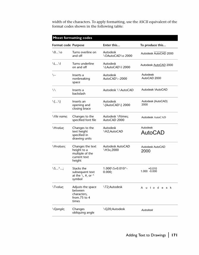
width of the characters. To apply formatting, use the ASCII equivalent of the format codes shown in the following table:
Mtext formatting codes
Format code Purpose Enter this... To produce this...
\0...\o Turns overline on and off
Autodesk \OAutoCAD\o 2000
\L...\l Turns underline on and off
Autodesk \LAutoCAD\l 2000
\~ Inserts a nonbreaking space
Autodesk AutoCAD\~2000
\\ Inserts a backslash
Autodesk \\AutoCAD
\{...\} Inserts an opening and closing brace
Autodesk \{AutoCAD\} 2000
\File name; Changes to the specified font file
Autodesk \Ftimes; AutoCAD 2000
\Hvalue; Changes to the text height specified in drawing units
Autodesk \H2;AutoCAD
\Hvaluex; Changes the text height to a multiple of the current text height
Autodesk AutoCAD \H3x;2000
\S...^...; Stacks the subsequent text at the \, #, or ^ symbol
1.000\S+0.010^-0.000;
\Tvalue; Adjusts the space between characters, from.75 to 4 times
\T2;Autodesk
\Qangle; Changes obliquing angle
\Q20;Autodesk
Adding Text to Drawings | 171

Use curly braces ({ }) to apply a format change only to the text within the braces. You can nest braces up to eight levels deep.
You also can enter the ASCII equivalent for control codes within lines or paragraphs to indicate formatting or special characters, such as tolerance or dimensioning symbols.
The following control characters can be used to create the text in the illustra-tion. (For the ASCII equivalent of this string see the example below.)
{{\H1.5x; Big text} \A2; over text\A1;/\A0; under text}
Using control characters to format text
This example creates an Mtext object whose text is formatted as illustrated above.
Sub Ch4_FormatMText() Dim mtextObj As AcadMText Dim insertPoint(0 To 2) As Double Dim width As Double Dim textString As String insertPoint(0) = 2 insertPoint(1) = 2 insertPoint(2) = 0 width = 4 ’ Define the ASCII characters for the control characters Dim OB As Long ’ Open Bracket { Dim CB As Long ’ Close Bracket } Dim BS As Long ’ Back Slash \ Dim FS As Long ’ Forward Slash / Dim SC As Long ’ Semicolon ;
\Wvalue; Changes width factor to produce wide text
\W2;Autodesk
\A Sets the alignment value; valid values: 0, 1, 2 (bottom, center, top)
\A1;1\S1/2
Mtext formatting codes (continued)
Format code Purpose Enter this... To produce this...
Big text over text/under text
172 | Chapter 4 Creating and Editing AutoCAD Entities
OB = Asc("{") CB = Asc("}") BS = Asc("\") FS = Asc("/") SC = Asc(";") ’ Assign the text string the following line of control ’ characters and text characters: ’ {{\H1.5x; Big text}\A2; over text\A1;/\A0; under text} textString = Chr(OB) + Chr(OB) + Chr(BS) + "H1.5x" _ + Chr(SC) + "Big text" + Chr(CB) + Chr(BS) + "A2" _ + Chr(SC) + "over text" + Chr(BS) + "A1" + Chr(SC) _ + Chr(FS) + Chr(BS) + "A0" + Chr(SC) + "under text" _ + Chr(CB) ’ Create a text Object in model space Set mtextObj = ThisDrawing.ModelSpace. _ AddMText(insertPoint, width, textString) ZoomAllEnd Sub
Formatting Multiline Text ObjectsYou can set the MText object properties that control style, text justification, and the size and rotation of the text boundary. These settings affect all text within the text boundary, not specific words or characters.
The StyleName property sets the default fonts and formatting characteristics for new text. As you create text, you can select which style you want to use from a list of existing styles.
When you change the style of an MText object that has character formatting applied to any portion of the text, the style is applied to the entire object, and some formatting of characters might not be retained. For instance, changing from a TrueType style to a style using an SHX font or to another TrueType font causes the text to use the new font for the entire object, and any char-acter formatting is lost.
Justification controls both text alignment and text flow based on a specified justification point. Text is justified with respect to the left and right text boundaries. Text flows from the middle, the top, or the bottom of the para-graph with respect to the top and bottom text boundaries. The top and bot-tom boundaries are based on the top and bottom lines of the multiline text object. AutoCAD offers nine justification settings: Top Left (TL), Top Center (TC), Top Right (TR), Middle Left (ML), Middle Center (MC), Middle Right (MR), Bottom Left (BL), Bottom Center (BC), and Bottom Right (BR).
Adding Text to Drawings | 173

Use the AttachmentPoint property to change the justification of MText.
The Rotation property controls the angle of rotation of the text boundary.
Using Unicode Characters, Control Codes, and Special Characters
You can use Unicode characters, control codes, and special characters in your text string to represent symbols. (All non-text characters must be entered as their ASCII equivalent.)
top left:left-aligned
top right:right-aligned
top center:centered
middle right:right-aligned
middle center:centered
middle left:left-aligned
bottom left:left-aligned
bottom center:centered
bottom right:right-aligned
174 | Chapter 4 Creating and Editing AutoCAD Entities

You can create special characters by entering the following Unicode character strings:
In addition to using Unicode characters for special characters, you can spec-ify a special character by including control information in the text string. Use a pair of percent signs (%%) to introduce each control sequence.
This control code works with standard AutoCAD text and PostScript fonts:
%%nnn Draws character number nnn.
In a VB or VBA text string, the example above would be entered as
Dim percent as Longpercent = ASC(“%”)TextString = chr(percent) + chr(percent) + “nnn”
These control codes work with standard AutoCAD text fonts only:
Unicode character descriptions
Unicode character Description
\U+00B0 Degree symbol
\U+00B1 Plus/minus tolerance symbol
\U+2205 Diameter dimensioning symbol
Control code descriptions
Control code Description
%%o Toggles overscore mode on and off
%%u Toggles underscore mode on and off
%%d Draws degree symbol
%%p Draws plus and minus tolerance symbol
%%c Draws diameter dimensioning symbol
%%% Draws single percent sign
Adding Text to Drawings | 175

Substituting Fonts
You can designate fonts to be substituted for other fonts or as defaults when AutoCAD cannot find a font specified in a drawing.
The fonts used for the text in your drawing are determined by the text style and, for MText, by individual font formats applied to sections of text. Some-times you might want to ensure that your drawing uses only certain fonts, or perhaps you might want to convert the fonts you used to other fonts. You can use any text editor to create font mapping tables for both of these purposes.
You can use these font mapping tables to enforce corporate font standards, or to facilitate offline printing. For example, if you share drawings with con-sultants, you may want to use a font mapping table to specify what font AutoCAD substitutes when it encounters text created with another font. Sim-ilarly, to edit the drawing using quicker-drawing SHX fonts, and then switch to more complex fonts for the final plot, you can set up a font mapping table that converts each SHX font to an equivalent.
The font mapping table is a plain ASCII text (FMP) file containing one font mapping per line. Each line contains the base name of the font file (with no directory name or path) followed by a semicolon (;) and the name of the sub-stitute font file. The substitute file name includes a file extension such as .ttf.
For example, you could use the following entry in a font map table to specify that the times.ttf TrueType font file be substituted for the romanc.shx font file:
romanc.shx; times.ttf
AutoCAD comes with a default font mapping table. You can edit this file using any ASCII text editor. You also can specify a different font mapping table file by using the FontFileMap property on the Preferences object.
Specifying an Alternative Default FontIf your drawing specifies a font that is not currently on your system, AutoCAD automatically substitutes the font designated as your alternate font. By default, AutoCAD uses the simplex.shx file. However, you can specify a different font if necessary. Use the AltFontFile property on the Preferences object to set the alternative font file name.
If you use a text style that uses a Big Font, you can map it to another font using the AltFontFile property. This system variable uses a default font file pair of txt.shx, bigfont.shx.
176 | Chapter 4 Creating and Editing AutoCAD Entities

The following table shows the font substitution rules used by AutoCAD when a font file cannot be located when a drawing is opened:
Checking Spelling
During a spelling check, AutoCAD matches the words in the drawing to the words in the current main dictionary. Any words you add are stored in the custom dictionary that is current at the time of the spelling check. For exam-ple, you can add proper names so that AutoCAD no longer identifies them as misspelled words.
To check spelling in another language, you can change to a different main dictionary.
There is no method for checking spelling provided in AutoCAD ActiveX Automation. However, you can specify a different main dictionary using the MainDictionary property, or a different custom dictionary using the CustomDictionary property on the Preferences object.
Font substitution rules
File extension
Mapping order (1st)
(2nd) (3rd) (4th)
TTF Use FONTMAP value
Use font defined in text style
Windows substitutes a similar font
SHX Use FONTMAP value
Use font defined in text style
Use FONTALT Prompt for new font
PFB Use FONTMAP value
Use FONTALT Prompt for new font
Adding Text to Drawings | 177

178

In This Chapter
Dimensioning and Tolerancing
5■ Reviewing Dimensioning
Concepts
■ Creating Dimensions
■ Editing Dimensions
■ Working with Dimension Styles
■ Dimensioning in Model Space and Paper Space
■ Creating Leaders and Annotation
■ Creating Geometric Tolerances
Dimensions add measurements to a drawing. Tolerances
specify by how much a dimension can vary. With
ActiveX Automation, dimensions can be managed with
dimension styles and overrides.
179

Reviewing Dimensioning Concepts
Dimensions show the geometric measurements of objects, the distances or angles between objects, or the X and Y coordinates of a feature. AutoCAD provides three basic types of dimensioning: linear, radial, and angular. Linear dimensions include aligned, rotated, and ordinate dimensions. A simple example of each is shown here:
You can create dimensions for lines, multilines, arcs, circles, and polyline seg-ments, or you can create dimensions that standalone.
AutoCAD draws dimensions on the current layer. Every dimension has a dimension style associated with it, whether it’s the default or one you define. The style controls characteristics such as color, text style, and linetype scale. Thickness information is not supported. Style families allow for subtle mod-ifications to a base style for different types of dimensions. Overrides allow for style modifications to a specific dimension.
radius
angular
aligned
horizontal
diameter
continuedbaseline
vertical
ordinate dimensions
180 | Chapter 5 Dimensioning and Tolerancing

Looking at the Parts of a Dimension
This section briefly defines the parts of a dimension.
A dimension line is a line that indicates the direction and extent of a dimen-sion. For an angular dimension, the dimension line is an arc. Extension lines, also called projection lines or witness lines, extend from the feature being dimensioned to the dimension line. Arrowheads, also called symbols of ter-mination or just termination, are added to each end of the dimension line. Dimension text is a text string that usually indicates the actual measurement. The text may also include prefixes, suffixes, and tolerances. A leader is a solid line leading from some annotation to the referenced feature. A center mark is a small cross that marks the center of a circle or arc. Centerlines are broken lines that mark the center of a circle or arc.
Defining the Dimension System Variables
The dimensioning system variables control the appearance of dimensions. The dimension system variables include: DIMAUNIT, DIMUPT, DIMTOFL, DIMFIT, DIMTIH, DIMTOH, DIMJUST, and DIMTAD. You can set these variables by using the SetVariable method. For example, the following line of code sets the DIMAUNIT system variable (the units format for angular dimensions) to radians (3):
ThisDrawing.SetVariable "DIMAUNIT", 3
continuedarrowhead
dimension line
extension line
leader
dimension text
center lines
Reviewing Dimensioning Concepts | 181

Setting Dimension Text Styles
Dimension text refers to any kind of text associated with dimensions, includ-ing measurements, tolerances (both lateral and geometric), prefixes, suffixes, and textual notes in single-line or paragraph form. You can use the default measurement computed by AutoCAD as the text, supply your own text, or suppress the text entirely. You can use dimension text to add information, such as special manufacturing procedures or assembly instructions.
Single-line dimension text uses the active text style as specified by the ActiveTextStyle property. Paragraphs of text use the active text style with any modifications you make in your text string.
Understanding Leader Lines
A default leader line is a straight line with an arrowhead that refers to a fea-ture in a drawing. Usually, a leader’s function is to connect annotation with the feature. Annotation in this case means paragraph text, blocks, or feature control frames. Such leader lines are different from the simple leader lines AutoCAD creates automatically for radial, diameter, and linear dimensions whose text won’t fit between extension lines.
leader
182 | Chapter 5 Dimensioning and Tolerancing

Leader objects are associated with the annotation, so when the annotation is edited, the leader is updated accordingly. You can copy annotation used else-where in a drawing and append it to a leader, or you can create a new annotation. You can also create a leader with no annotation appended.
Understanding Associative Dimensions
Associative dimensions are dimensions in which all the lines, arrowheads, arcs, and text are drawn as a single-dimension object. The DIMASO system variable controls associative dimensioning and is on by default. If DIMASO is off, the dimension line, extension lines, arrowheads, leaders, and dimension text are drawn as separate objects. You can create a nonassociative dimension if you need to alter the dimension in ways that are not controlled by vari-ables. In general, however, associative dimensions are easier to maintain because they can be modified as a single object.
To set or query a system variable, use the SetVariable and GetVariable methods.
Creating Dimensions
You can create linear, radial, angular, and ordinate dimensions.
When creating dimensions, the active dimension style is used. Once created, you can modify the extension line origins, the dimension text location, and the dimension text content and its angle relative to the dimension line. You can also change the dimension style used by the dimension.
Creating Linear Dimensions
Linear dimensions can be aligned or rotated. Aligned dimensions have the dimension line parallel to the line along which the extension line origins lie. Rotated dimensions have the dimension line placed at an angle to the exten-sion line origins.
To create a linear dimension, use the AddDimAligned, AddDimRotated, or AddDim3PointAligned methods. After you create linear dimensions, you can modify the text, the angle of the text, or the angle of the dimension line. In
Creating Dimensions | 183

these illustrations, the extension line origins are designated explicitly. The resulting dimension line location is also shown:
To create an aligned dimension, use the AddDimAligned method. This method requires three coordinates as input: the origin of both extension lines and the text position.
To create a rotated dimension, use the AddDimRotated method. This method requires three coordinates and the angle of the dimension line as input. The three coordinates are the origin of both extension lines and the text position. The angle must be provided in radians and represents the angle of rotation for the dimension line.
Creating Radial Dimensions
Radial dimensions measure the radii and diameters of arcs and circles. To cre-ate a radial dimension, use the AddDimRadial method.
Different types of radial dimensions are created depending on the size of the circle or arc, the TextPosition property, and the values in the DIMUPT, DIMTOFL, DIMFIT, DIMTIH, DIMTOH, DIMJUST, and DIMTAD dimension system variables. (System variables can be queried or set using the GetVariable and SetVariable methods.)
For horizontal dimension text, if the angle of the dimension line is more than 15 degrees from horizontal, and is outside the circle or arc, AutoCAD draws a hook line, also called a landing or dogleg. The hook line is one arrow-
aligned rotated 315 degrees
horizontal vertical
184 | Chapter 5 Dimensioning and Tolerancing

head long, and is placed next to the dimension text, as shown in the first two illustrations:
To create radial dimensions, use the AddDimRadial or AddDimDiametric methods. These methods require three values as input: the coordinate of the circle or arc’s center, the coordinate for the leader attachment, and the length of the leader.
These methods use the LeaderLength parameter as the distance from the ChordPoint to the point where the dimension will do a horizontal hook line to the annotation text (or stop if no hook line is necessary).
Creating a radial dimension
This example creates a radial dimension in model space.
Sub Ch5_CreateRadialDimension() Dim dimObj As AcadDimRadial Dim center(0 To 2) As Double Dim chordPoint(0 To 2) As Double Dim leaderLen As Integer ’ Define the dimension center(0) = 0 center(1) = 0 center(2) = 0 chordPoint(0) = 5 chordPoint(1) = 5 chordPoint(2) = 0 leaderLen = 5 ’ Create the radial dimension in model space Set dimObj = ThisDrawing.ModelSpace. _ AddDimRadial(center, chordPoint, leaderLen) ZoomAllEnd Sub
Creating Dimensions | 185

NOTE The LeaderLength setting is only used during the creation of the dimen-sion (and even then only if the dimension is set to use the default text position value). After the dimension is closed for the first time, changing the Leader-Length value will not affect how the dimension displays, but the new setting will be stored and will show up in DXF, LISP, and ADSRX applications.
Creating Angular Dimensions
Angular dimensions measure the angle between two lines or three points. For example, you can use them to measure the angle between two radii of a cir-cle. The dimension line forms an arc.
To create an angular dimension, use the AddDimAngular method. This method requires three values as input: the angle vertex, the origins of the extension lines, and the text location. The AngleVertex is the center of the circle or arc, or the common vertex between the two lines being dimen-sioned. The origins of the extension lines are the points through which the two extension lines pass.
The AngleVertex can be the same as one of the origin points. If you need extension lines they will be added automatically.
Creating an angular dimension
This example creates an angular dimension in model space.
Sub Ch5_CreateAngularDimension() Dim dimObj As AcadDimAngular Dim angVert(0 To 2) As Double Dim FirstPoint(0 To 2) As Double Dim SecondPoint(0 To 2) As Double Dim TextPoint(0 To 2) As Double ’ Define the dimension angVert(0) = 0 angVert(1) = 5 angVert(2) = 0 FirstPoint(0) = 1
186 | Chapter 5 Dimensioning and Tolerancing

FirstPoint(1) = 7 FirstPoint(2) = 0 SecondPoint(0) = 1 SecondPoint(1) = 3 SecondPoint(2) = 0 TextPoint(0) = 3 TextPoint(1) = 5 TextPoint(2) = 0 ’ Create the angular dimension in model space Set dimObj = ThisDrawing.ModelSpace. _ AddDimAngular(angVert, FirstPoint, SecondPoint, TextPoint) ZoomAllEnd Sub
Creating Ordinate Dimensions
Ordinate, or datum, dimensions measure the perpendicular distance from an origin point, called the datum, to a dimensioned feature, such as a hole in a part. These dimensions prevent escalating errors by maintaining accurate off-sets of the features from the datum.
Ordinate dimensions consist of an X or Y ordinate with a leader line. X-datum ordinate dimensions measure the distance of a feature from the datum along the X axis. Y-datum ordinate dimensions measure the same dis-tance along the Y axis. AutoCAD uses the origin of the current UCS to deter-mine the measured coordinates. The absolute value of the coordinate is used.
The text is aligned with the ordinate leader line regardless of the text orien-tation defined by the current dimension style. You can accept the default text or supply your own.
To create an ordinate dimension, use the AddDimOrdinate method. This method requires three values as input: a coordinate specifying the point to be dimensioned (A), a coordinate specifying the end of the leader (B), and a Boolean flag specifying whether the dimension is an X-datum ordinate dimension or a Y-datum ordinate dimension. If you enter TRUE for the Bool-ean flag, the method will create an X-datum ordinate dimension. If you enter FALSE, it will create a Y-datum ordinate dimension.
B
A
Creating Dimensions | 187

Creating an ordinate dimension
This example creates an ordinate dimension in model space.
Sub Ch5_CreatingOrdinateDimension() Dim dimObj As AcadDimOrdinate Dim definingPoint(0 To 2) As Double Dim leaderEndPoint(0 To 2) As Double Dim useXAxis As Long ’ Define the dimension definingPoint(0) = 5 definingPoint(1) = 5 definingPoint(2) = 0 leaderEndPoint(0) = 10 leaderEndPoint(1) = 5 leaderEndPoint(2) = 0 useXAxis = 5 ’ Create an ordinate dimension in model space Set dimObj = ThisDrawing.ModelSpace. _ AddDimOrdinate(definingPoint, _ leaderEndPoint, useXAxis) ZoomAllEnd Sub
Editing Dimensions
As with other graphical objects in AutoCAD, you can edit dimensions using the standard methods and properties provided for the object.
The following properties are available for most dimension objects:
Rotation Specifies the rotation angle in radians for the dimension line.
StyleName Specifies the name of the dimension style.
Specifies the text string for the dimension.
Specifies the text string for the dimension.
TextPosition Specifies the dimension text position.
TextRotation Specifies the rotation angle of the dimension text.
Measurement Specifies the actual measurement for the dimension.
188 | Chapter 5 Dimensioning and Tolerancing
In addition, certain dimension objects provide properties for editing the extension line origins and leader length.
The following methods are included for dimension object editing:
ArrayPolar Creates a polar array.
ArrayRectangular
Creates a rectangular array.
Copy Copies the dimension object.
Erase Erases the dimension object.
Mirror Mirrors the dimension object.
Move Moves the dimension object.
Rotate Rotates the dimension object.
ScaleEntity Scales the dimension object.
Overriding dimension text
The dimension value that is displayed can be replaced using the TextOverride property. Using this property you can completely replace the displayed value of the dimension, or you can append text to the value. This example appends some text to the value so that both the string and the dimension value are displayed.
Sub Ch5_OverrideDimensionText() Dim dimObj As AcadDimAligned Dim point1(0 To 2) As Double Dim point2(0 To 2) As Double Dim location(0 To 2) As Double ’ Define the dimension point1(0) = 5#: point1(1) = 3#: point1(2) = 0# point2(0) = 10#: point2(1) = 3#: point2(2) = 0# location(0) = 7.5: location(1) = 5#: location(2) = 0# ’ Create an aligned dimension object in model space Set dimObj = ThisDrawing.ModelSpace. _ AddDimAligned(point1, point2, location) ’ Change the text string for the dimension dimObj.TextOverride = "The value is <>" dimObj.UpdateEnd Sub
Editing Dimensions | 189

Working with Dimension Styles
A named dimension style is a group of settings that determines the appear-ance of the dimension. Using named dimension styles, you can establish and enforce drafting standards for drawings.
All dimensions are created using the active dimension style. If you don’t define or apply a style before creating dimensions, AutoCAD applies the default style, STANDARD. To set the active dimension style, use the ActiveDimStyle property.
To set up a parent dimension style, you begin by naming and saving a style. The new style is based on the current style and includes all subsequent changes to the layout of the dimension parts (DDIM Geometry dialog box), the positioning of text (DDIM Format dialog box), and the appearance of annotation (DDIM Annotation dialog box). Annotation in this case means primary and alternate units, tolerances, and text.
To create a new dimension style, use the Add method. This method requires as input the name of the new dimension style.
AutoCAD ActiveX Automation allows you to add new dimension styles, and to change the active dimension style. You can also change the dimension style associated with a given dimension through the StyleName property.
You can also copy an existing style or set of overrides. Use the CopyFrom method to copy a dimension style from a source object to a newly dimension style. The source object can be another DimStyle object, a dimension, Toler-ance, or Leader object, or even a Document object. If you copy the style set-tings from another dimension style, the style is duplicated exactly. If you copy the style settings from a dimension, Tolerance, or Leader object, the cur-rent settings, including any object overrides, are copied to the new style. If you copy the style of a Document object, the active dimension style, plus any drawing overrides, are copied to the new style.
190 | Chapter 5 Dimensioning and Tolerancing

Copying dimension styles and overrides
This example creates three new dimension styles and copies the current set-tings for the document, a given dimension style, and a given dimension to each new dimension style respectively. By following the appropriate setup before running this example, you will find that different dimension styles have been created.
1 Create a new drawing and make it the active drawing.
2 Create a linear dimension in the new drawing. This dimension should be the only object in the drawing.
3 Using the OPM, change the color of the dimension line to yellow.
4 Change the DIMCLRD system variable to 5 (blue).
5 Run the following example:
Sub Ch5_CopyDimStyles() Dim newStyle1 As AcadDimStyle Dim newStyle2 As AcadDimStyle Dim newStyle3 As AcadDimStyle Set newStyle1 = ThisDrawing.DimStyles.Add _ ("Style 1 copied from a dim") Call newStyle1.CopyFrom(ThisDrawing.ModelSpace(0)) Set newStyle2 = ThisDrawing.DimStyles.Add _ ("Style 2 copied from Style 1") Call newStyle2.CopyFrom(ThisDrawing.DimStyles.Item _ ("Style 1 copied from a dim")) Set newStyle2 = ThisDrawing.DimStyles.Add _ ("Style 3 copied from the running drawing values") Call newStyle2.CopyFrom(ThisDrawing)End Sub
Open the DIMSTYLE dialog. You should now have 3 dimension styles listed. Style 1 should have a yellow dimension line. Style 2 should be the same as Style 1. Style 3 should have a blue dimension line.
Working with Dimension Styles | 191

Overriding the Dimension Style
Each dimension has the capability of overriding settings in the dimension style for that dimension. The following properties are available for most dimension objects:
AltRoundDistance
Specifies the rounding of alternate units.
AngleFormat
Specifies the unit format for angular dimensions.
Arrowhead1Block, Arrowhead2Block
Specifies the block to use as the custom arrowhead for the dimension line.
Arrowhead1Type, Arrowhead2Type
Specifies the type of arrowhead for the dimension line.
ArrowheadSize
Specifies the size of dimension line arrowheads, leader line arrowheads, and hook lines.
CenterMarkSize
Specifies the size of the center mark for radial and diameter dimensions.
CenterType
Specifies the type of center mark for radial and diameter dimensions.
DecimalSeparator
Specifies the character to be used as the decimal separator in decimal dimension and tolerance values.
DimensionLineColor
Specifies the color of the dimension line for a dimension, leader, or tolerance object.
DimensionLineWeight
Specifies the line weight for the dimension lines.
192 | Chapter 5 Dimensioning and Tolerancing

DimLine1Suppress, DimLine2Suppress
Specifies the suppression of the dimension lines.
DimLineInside
Specifies the display of dimension lines inside the extension lines only.
ExtensionLineColor
Specifies the color for dimension extension lines.
ExtensionLineExtend
Specifies the distance the extension line extends beyond the dimension line.
ExtensionLineOffset
Specifies the distance the extension lines are offset from the origin points.
ExtensionLineWeight
Specifies the line weight for the extension lines.
ExtLine1EndPoint, ExtLine2EndPoint
Specifies the endpoint of extension lines.
ExtLine1StartPoint, ExtLine2StartPoint
Specifies the start point of extension lines.
ExtLine1Suppress, ExtLine2Suppress
Specifies the suppression of extension lines.
Fit
Specifies the placement of text and arrowheads inside or outside extension lines.
ForceLineInside
Specifies if a dimension line is drawn between the extension lines even when the text is placed outside the extension lines.
FractionFormat
Specifies the format of fractional values in dimensions and tolerances.
Working with Dimension Styles | 193

HorizontalTextPosition
Specifies the horizontal justification for dimension text.
LinearScaleFactor
Specifies a global scale factor for linear dimensioning measurements.
PrimaryUnitsPrecision
Specifies the number of decimal places displayed for the primary units of a dimension or tolerance.
SuppressLeadingZeros, SuppressTrailingZeros
Specifies the suppression of leading and trailing zeros in dimension values.
SuppressZeroFeet, SuppressZeroInches
Specifies the suppression of a zero foot and zero inch measurement in dimension values.
TextColor
Specifies the color of the text for dimension and tolerance objects.
TextGap
Specifies the distance between the dimension text and the dimension line when you break the dimension line to accommodate dimension text.
TextHeight
Specifies the height for the dimension or tolerance text.
TextInside
Specifies if the dimension text is to be drawn inside the extension lines.
TextInsideAlign
Specifies the position of dimension text inside the extension lines for all dimension types except ordinate.
TextMovement
Specifies how dimension text is drawn when text is moved.
194 | Chapter 5 Dimensioning and Tolerancing

TextOutsideAlign
Specifies the position of dimension text outside the extension lines for all dimension types except ordinate.
TextPosition
Specifies the dimension text position.
TextPrecision
Specifies the precision of angular dimension text.
TextPrefix
Specifies the dimension value prefix.
TextRotation
Specifies the rotation angle of the dimension text.
TextSuffix
Specifies the dimension value suffix.
ToleranceDisplay
Specifies if tolerances are displayed with the dimension text.
ToleranceHeightScale
Specifies a scale factor for the text height of tolerance values relative to the dimension text height.
ToleranceJustification
Specifies the vertical justification of tolerance values relative to the nominal dimension text.
ToleranceLowerLimit
Specifies the minimum tolerance limit for dimension text.
TolerancePrecision
Specifies the precision of tolerance values in primary dimensions.
ToleranceSuppressLeadingZeros
Specifies the suppression of leading zeros in tolerance values.
Working with Dimension Styles | 195
ToleranceSuppressTrailingZeros
Specifies the suppression of trailing zeros in dimension values.
ToleranceUpperLimit
Specifies the maximum tolerance limit for dimension text.
UnitsFormat
Specifies the unit format for all dimensions except angular.
VerticalTextPosition
Specifies the vertical position of text in relation to the dimension line.
Entering a user-defined suffix for an aligned dimension
This example creates an aligned dimension in model space and uses the TextSuffix property to allow the user to change the text suffix for the dimen-sion.
Sub Ch5_AddTextSuffix() Dim dimObj As AcadDimAligned Dim point1(0 To 2) As Double Dim point2(0 To 2) As Double Dim location(0 To 2) As Double Dim suffix As String ’ Define the dimension point1(0) = 0: point1(1) = 5: point1(2) = 0 point2(0) = 5: point2(1) = 5: point2(2) = 0 location(0) = 5: location(1) = 7: location(2) = 0 ’ Create an aligned dimension object in model space Set dimObj = ThisDrawing.ModelSpace. _ AddDimAligned(point1, point2, location) ThisDrawing.Application.ZoomAll ’ Allow the user to change the text suffix for the dimension suffix = InputBox("Enter a new text suffix for the dimension" _ , "Set Dimension Suffix", ":SUFFIX") ’ Apply the change to the dimension dimObj.TextSuffix = suffix ThisDrawing.Regen acAllViewportsEnd Sub
196 | Chapter 5 Dimensioning and Tolerancing

Dimensioning in Model Space and Paper Space
You can draw dimensions in both paper space and model space. However, if the geometry you’re dimensioning is in model space, it’s better to draw dimensions in model space, because AutoCAD places the definition points in the space where the geometry is drawn.
If you draw a dimension in paper space that describes geometry in your model, the paper space dimension does not change when you use editing commands or change the magnification of the display in the model space viewport. The location of the paper space dimensions also stays the same when you change a view from paper space to model space.
If you’re dimensioning in paper space and the global scale factor for linear dimensioning (the DIMLFAC system variable) is set at less than 0, the distance measured is multiplied by the absolute value of DIMLFAC. If you’re dimen-sioning in model space, the value of 1.0 is used even if DIMLFAC is less than 0. AutoCAD computes a value for DIMLFAC if you change the variable at the Dim prompt and select the Viewport option. AutoCAD calculates the scaling of model space to paper space and assigns the negative of this value to DIMLFAC.
Creating Leaders and Annotation
A leader is a line that connects some annotation to a feature in a drawing. Leaders and their annotation are associative, which means if you modify the annotation, the leader updates accordingly. Don’t confuse the Leader object with the leader line AutoCAD automatically generates as part of a dimension line.
Creating a Leader Line
You can create a leader line from any point or feature in a drawing and con-trol its appearance as you draw it. Leaders can be straight line segments or smooth spline curves. Leader color is controlled by the current dimension line color. Leader scale is controlled by the overall dimension scale set in the active dimension style. The type and size of the arrowhead, if one is present, is controlled by the first arrowhead defined in the active style.
Dimensioning in Model Space and Paper Space | 197
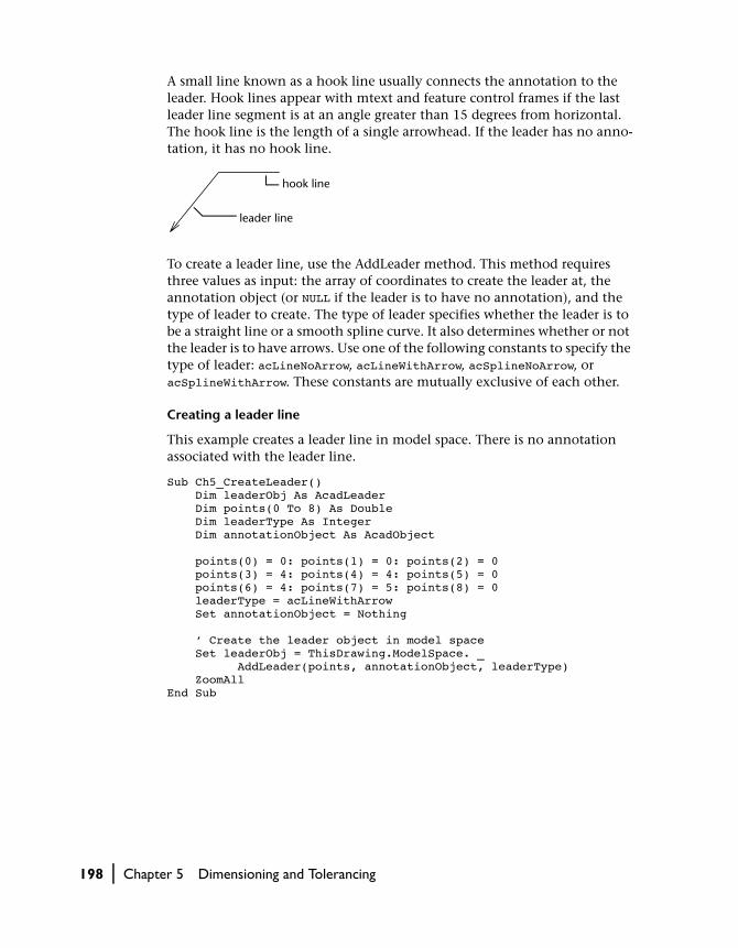
A small line known as a hook line usually connects the annotation to the leader. Hook lines appear with mtext and feature control frames if the last leader line segment is at an angle greater than 15 degrees from horizontal. The hook line is the length of a single arrowhead. If the leader has no anno-tation, it has no hook line.
To create a leader line, use the AddLeader method. This method requires three values as input: the array of coordinates to create the leader at, the annotation object (or NULL if the leader is to have no annotation), and the type of leader to create. The type of leader specifies whether the leader is to be a straight line or a smooth spline curve. It also determines whether or not the leader is to have arrows. Use one of the following constants to specify the type of leader: acLineNoArrow, acLineWithArrow, acSplineNoArrow, or acSplineWithArrow. These constants are mutually exclusive of each other.
Creating a leader line
This example creates a leader line in model space. There is no annotation associated with the leader line.
Sub Ch5_CreateLeader() Dim leaderObj As AcadLeader Dim points(0 To 8) As Double Dim leaderType As Integer Dim annotationObject As AcadObject points(0) = 0: points(1) = 0: points(2) = 0 points(3) = 4: points(4) = 4: points(5) = 0 points(6) = 4: points(7) = 5: points(8) = 0 leaderType = acLineWithArrow Set annotationObject = Nothing ’ Create the leader object in model space Set leaderObj = ThisDrawing.ModelSpace. _ AddLeader(points, annotationObject, leaderType) ZoomAllEnd Sub
hook line
leader line
198 | Chapter 5 Dimensioning and Tolerancing
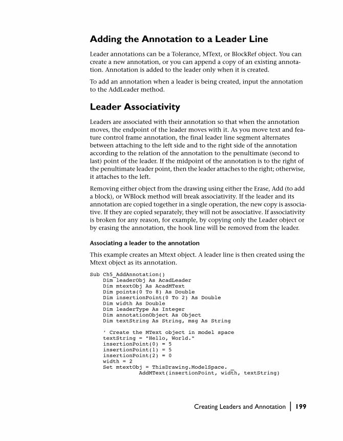
Adding the Annotation to a Leader Line
Leader annotations can be a Tolerance, MText, or BlockRef object. You can create a new annotation, or you can append a copy of an existing annota-tion. Annotation is added to the leader only when it is created.
To add an annotation when a leader is being created, input the annotation to the AddLeader method.
Leader Associativity
Leaders are associated with their annotation so that when the annotation moves, the endpoint of the leader moves with it. As you move text and fea-ture control frame annotation, the final leader line segment alternates between attaching to the left side and to the right side of the annotation according to the relation of the annotation to the penultimate (second to last) point of the leader. If the midpoint of the annotation is to the right of the penultimate leader point, then the leader attaches to the right; otherwise, it attaches to the left.
Removing either object from the drawing using either the Erase, Add (to add a block), or WBlock method will break associativity. If the leader and its annotation are copied together in a single operation, the new copy is associa-tive. If they are copied separately, they will not be associative. If associativity is broken for any reason, for example, by copying only the Leader object or by erasing the annotation, the hook line will be removed from the leader.
Associating a leader to the annotation
This example creates an Mtext object. A leader line is then created using the Mtext object as its annotation.
Sub Ch5_AddAnnotation() Dim leaderObj As AcadLeader Dim mtextObj As AcadMText Dim points(0 To 8) As Double Dim insertionPoint(0 To 2) As Double Dim width As Double Dim leaderType As Integer Dim annotationObject As Object Dim textString As String, msg As String ’ Create the MText object in model space textString = "Hello, World." insertionPoint(0) = 5 insertionPoint(1) = 5 insertionPoint(2) = 0 width = 2 Set mtextObj = ThisDrawing.ModelSpace. _ AddMText(insertionPoint, width, textString)
Creating Leaders and Annotation | 199

’ Data for Leader points(0) = 0: points(1) = 0: points(2) = 0 points(3) = 4: points(4) = 4: points(5) = 0 points(6) = 4: points(7) = 5: points(8) = 0 leaderType = acLineWithArrow ’ Create the Leader object in model space and associate ’ the MText object with the leader Set annotationObject = mtextObj Set leaderObj = ThisDrawing.ModelSpace. _ AddLeader(points, annotationObject, leaderType) ZoomAllEnd Sub
Editing Leader Associativity
Except for the associativity relation between the leader and annotation, the leader and its annotation are entirely separate objects in your drawing. Editing of the leader does not affect the annotation, and editing of the anno-tation does not affect the leader.
Although text annotation is created using the DIMCLRT, DIMTXT, and DIMTXSTY system variables to define its color, height, and style, it cannot be changed by these system variables because it is not a true dimension object. Text annotation must be edited the same way as any other MText object.
Use the Evaluate method to evaluate the relation of the leader to its associ-ated annotation. This method will update the leader geometry if necessary.
Editing Leaders
Any modifications to leader annotation that change its position affect the position of the endpoint of the associated leader. Also, rotating the annota-tion causes the leader hook line (if any) to rotate.
To resize a leader, you can scale it. Scaling updates only the scale of the selected object. For example, if you scale the leader, the annotation stays in the same position relative to the leader endpoint but isn’t scaled.
In addition to scaling, you can also move, mirror, and rotate a leader. Use the ScaleEntity, Move, Mirror, and Rotate methods to edit the leader. You can also change the text style associated with the annotation by using the Style-Name property.
200 | Chapter 5 Dimensioning and Tolerancing

Creating Geometric Tolerances
Geometric tolerancing shows deviations of form, profile, orientation, loca-tion, and runout of a feature. You add geometric tolerances in feature control frames. These frames contain all the tolerance information for a single dimension.
To create a geometric tolerance use the AddTolerance method. This method requires three values as input: the text string comprising the tolerance symbol, the location in the drawing to place the tolerance, and a directional vector specifying the direction of the tolerance.
You can also copy, move, erase, scale, and rotate tolerances.
A feature control frame consists of at least two compartments. The first contains a geometric characteristic symbol that represents the geometric characteristic to which a tolerance is being applied, for example, form, orien-tation, or runout. Form tolerances control straightness, flatness, circularity, cylindricity, and profiles of line and surface. In the previous illustration, the characteristic is position.
The second compartment contains the tolerance value. Where applicable, the tolerance value is preceded by a diameter symbol and followed by a mate-rial condition symbol.
primary, secondary, and tertiary datum reference letters
geometric characteristic symbol—in this case straightness
material conditions of datums
optional diameter symbol
tolerance value
Creating Geometric Tolerances | 201

Creating a geometric tolerance
This example creates a simple geometric tolerance in model space.
Sub Ch5_CreateTolerance() Dim toleranceObj As AcadTolerance Dim textString As String Dim insertionPoint(0 To 2) As Double Dim direction(0 To 2) As Double ’ Define the tolerance object textString = "Here is the Feature Control Frame" insertionPoint(0) = 5 insertionPoint(1) = 5 insertionPoint(2) = 0 direction(0) = 1 direction(1) = 1 direction(2) = 0 ’ Create the tolerance object in model space Set toleranceObj = ThisDrawing.ModelSpace. _ AddTolerance(textString, insertionPoint, direction) ZoomAllEnd Sub
Editing Tolerances
Tolerances are influenced by several system variables: DIMCLRD controls the color of the feature control frame; DIMCLRT controls the color of the toler-ance text; DIMGAP controls the gap between the feature control frame and the text; DIMTXT controls the size of the tolerance text; and DIMTXTSTY con-trols the style of the tolerance text. Use the SetVariable method to set the val-ues of system variables.
202 | Chapter 5 Dimensioning and Tolerancing

In This Chapter
Customizing Toolbars and Menus
6■ Understanding the MenuBar and
MenuGroups Collections
■ Loading Menu Groups
■ Changing the Menu Bar
■ Creating and Editing Pull-Down and Shortcut Menus
■ Creating and Editing Toolbars
■ Creating Macros
■ Creating Status-Line Help for Menu Items and Toolbar Items
■ Adding Entries to the Right-Click Menu
AutoCAD ActiveX Automation gives you extensive con-
trol over the customization of menus and toolbars in
the current AutoCAD session.
Using AutoCAD ActiveX/VBA, you can edit or augment
the existing menu structure, or you can completely
replace the current menu structure. You can also manip-
ulate toolbars and right-click menus.
Menu customization can improve productivity by
exposing application-specific tasks or by condensing
tasks with multiple steps into a single menu selection.
203

Understanding the MenuBar and MenuGroups Collections
AutoCAD ActiveX provides several menu-related objects. The two most important are the MenuBar collection and the MenuGroups collection. The MenuBar collection contains all the menus that are displayed in the AutoCAD menu bar.
The MenuGroups collection contains the menu groups that are loaded in the current AutoCAD session. These menu groups contain all the menus that are available to the AutoCAD session, some or all of which may be displayed on the AutoCAD menu bar. In addition to the menus, the menu groups also con-tain all the toolbars that are available to the current AutoCAD session.
Menu groups may also represent tile menus, screen menus, or tablet menus.
AutoCAD Application
MenuBar
PopupMenu
PopupMenus
Toolbars
MenuGroups
MenuGroup
204 | Chapter 6 Customizing Toolbars and Menus
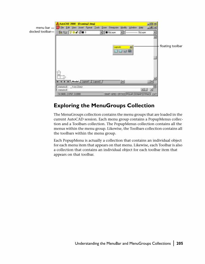
Exploring the MenuGroups Collection
The MenuGroups collection contains the menu groups that are loaded in the current AutoCAD session. Each menu group contains a PopupMenus collec-tion and a Toolbars collection. The PopupMenus collection contains all the menus within the menu group. Likewise, the Toolbars collection contains all the toolbars within the menu group.
Each PopupMenu is actually a collection that contains an individual object for each menu item that appears on that menu. Likewise, each Toolbar is also a collection that contains an individual object for each toolbar item that appears on that toolbar.
menu bardocked toolbar
floating toolbar
Understanding the MenuBar and MenuGroups Collections | 205

Loading Menu Groups
Menu groups are loaded into AutoCAD using the Load method. When using the Load method, set the BaseMenu parameter to TRUE to load a new menu group to the menu bar. This will load the menu group as a base menu in the same manner as the MENU command in AutoCAD.
To load a new menu group as a partial menu, omit the BaseMenu parameter. This will load the menu group in the same manner as the MENULOAD command in AutoCAD. Once loaded into the MenuGroups collection, partial menus can be inserted into the menu bar by using the InsertMenuInMenuBar method, or the InsertInMenuBar method.
AutoCAD Application
MenuBar
PopupMenu
PopupMenus
PopupMenu
PopupMenuItem
ToolbarItem
Toolbars
Toolbar
MenuGroups
MenuGroup
206 | Chapter 6 Customizing Toolbars and Menus

Once a menu group has been loaded, all the menus and toolbars defined by that menu group are available for use. You can
■ Add new menus to the menu bar■ Remove menus from the menu bar■ Rearrange menus on the menu bar■ Add new items to an existing menu or toolbar■ Remove items from an existing menu or toolbar■ Create new menus and toolbars■ Float or dock toolbars■ Enable or disable menu and toolbar items■ Check or uncheck a menu item■ Change the tag, label, or help string of a menu or toolbar item■ Reassign the macros associated to a menu or toolbar item
Loading a menu group
This example loads the menu file acad.mnc.
ThisDrawing.Application.MenuGroups.Load "acad.mnc"
NOTE You cannot edit image tile menu items, screen menus, or tablet menus using ActiveX Automation. However, you can load and unload these menu types using ActiveX Automation. For more information on these types of menus, see chapter 4, “Custom Menus” in the AutoCAD Customization Guide.
Creating New Menu Groups
AutoCAD ActiveX does not allow you to create new (empty) menu groups programmatically. However, you can load an existing menu group and save it out again with a new name and to a new menu file. You can then edit the menu group to contain the exact configuration you desire. This process of creating new menu groups based on existing menu groups has the advantage of automatically providing you with basic menus such as File, Window, and Help.
Loading Menu Groups | 207

Saving a menu group to a new file name
This example saves the first menu group in the menu groups collection to a file called MyMenu.mnc.
ThisDrawing.Application.MenuGroups.Item(0). _SaveAs "MyMenu.mnc", acMenuFileCompiled
Changing the Menu Bar
As we have already seen, the menu bar can be completely replaced by a new menu group if that group is loaded as the base menu. Additionally, individ-ual menus on the menu bar can be added, removed, or rearranged.
Inserting Menus in the Menu Bar
To insert an existing menu to the menu bar, use the InsertMenuInMenuBar or the InsertInMenuBar method. Both methods accomplish the same goal—they insert an existing menu into the menu bar.
The difference between the two methods is the object from which they are called. The InsertMenuInMenuBar method is called from the PopupMenus collection. Using this method you can insert any menu from the collection into a specified location on the menu bar. This method requires as input the name of the menu to insert and the location on the menu bar to insert it.
The InsertInMenuBar method is called directly from the PopupMenu object to be inserted. The only input this method requires is a location on the menu bar. The name of the menu is not needed because you are calling the method directly from the object to be inserted.
You should use whichever method is more convenient for your application.
Inserting a menu in the menu bar
This example creates a new menu called TestMenu and inserts a menu item into it. The menu item is assigned the OPEN command. The menu is then dis-played on the menu bar.
208 | Chapter 6 Customizing Toolbars and Menus

Sub Ch6_InsertMenu() ’ Define a variable for the current menu group Dim currMenuGroup As AcadMenuGroup Set currMenuGroup = ThisDrawing.Application. _ MenuGroups.Item(0) ’ Create a new menu Dim newMenu As AcadPopupMenu Set newMenu = currMenuGroup.Menus.Add("TestMenu") ’ Declare the variables for the menu item Dim newMenuItem As AcadPopupMenuItem Dim openMacro As String ’ Assign the macro string the VB equivalent of ’ "ESC ESC _open " and create the menu item openMacro = Chr(3) + Chr(3) + Chr(95) + "open" + Chr(32) Set newMenuItem = newMenu.AddMenuItem(newMenu.Count + 1, _ "Open", openMacro) ’ Display the menu on the menu bar currMenuGroup.Menus.InsertMenuInMenuBar "TestMenu", ""End Sub
Removing Menus from the Menu Bar
To remove a menu from the menu bar, use the RemoveMenuFromMenuBar or the RemoveFromMenuBar method. Both methods accomplish the same goal—they remove a menu from the menu bar.
The difference between the two methods is the object from which they are called. The RemoveMenuFromMenuBar method is called from the Popup-Menus collection. This method requires as input the name of the menu to remove, or the location on the menu bar of the menu to remove.
The RemoveFromMenuBar method is called directly from the PopupMenu object to be removed. This method does not require any input. The name of the menu is not needed because you are calling the method directly from the object to be removed.
You should use whichever method is more convenient for your application.
Changing the Menu Bar | 209

Removing a menu from the menu bar
This example will remove the menu added in the example “Inserting a menu in the menu bar” from the menu bar.
’ Remove the menu from the menu bar currMenuGroup.Menus.RemoveMenuFromMenuBar ("TestMenu")
NOTE Menus that have been removed from the menu bar are still available in their designated menu group. They are simply no longer visible to the user.
Rearranging Menu Items on the Menu Bar
To rearrange menus on the menu bar, insert and remove menus until the desired configuration is achieved.
Moving the first menu to the end of the menu bar
This example removes the first menu on the menu bar and inserts it as the last menu on the menu bar.
Sub Ch6_MoveMenu() ’ Define a variable to hold the menu to be moved Dim moveMenu As AcadPopupMenu Dim MyMenuBar As AcadMenuBar Set MyMenuBar = ThisDrawing.Application.menuBar ’ Set moveMenu equal to the first menu displayed ’ on the menu bar Set moveMenu = MyMenuBar.Item(0) ’ Remove the first menu from the menu bar MyMenuBar.Item(0).RemoveFromMenuBar ’ Add the menu back into the menu bar ’ in the last position on the bar moveMenu.InsertInMenuBar (MyMenuBar.count)End Sub
210 | Chapter 6 Customizing Toolbars and Menus

Creating and Editing Pull-Down and Shortcut Menus
AutoCAD ActiveX/VBA has the ability to customize two types of AutoCAD menus: pull-down menus and shortcut menus (sometimes called cursor menus). Both pull-down and shortcut menus are displayed as cascading menus. The shortcut menu can provide quick access to frequently used menu items such as Object Snap modes.
A pull-down menu can contain up to 999 menu items. A shortcut menu can contain up to 499 menu items. Both limits include all menus in the hierar-chy. If the number of menu items in a menu exceeds these limits, AutoCAD ignores the extra items. If a pull-down or shortcut menu is taller than the available space on the graphics screen, it is truncated to fit on the screen.
Pull-down menus are always pulled down from the menu bar, but the short-cut menu is always displayed at or near the crosshairs on the graphics screen. The handling for both menu types is the same except the shortcut menu cap-tion isn’t included on the menu bar. The shortcut menu caption is not dis-played at all. Access to the shortcut menu is through a single menu in the base menu group. The shortcut menu can be identified with the Shortcut-Menu property. If the ShortcutMenu property returns TRUE, then the queried menu is the shortcut menu for the group.
Creating New Menus
To create a new menu, use the Add method to add a new PopupMenu object to the PopupMenus collection.
To create a new shortcut menu, you must delete an existing shortcut menu. There can be only one shortcut menu per menu group. If there is no other shortcut menu in a menu group, you can add a menu with the label “POP0”. This will tell AutoCAD you want to create a shortcut menu.
The Add method requires as input the name (label) of the menu to add. This name becomes the title for the menu when it is loaded on the menu bar. The name is also the easiest way of identifying the menu within the collection.
The menu name can be a simple string or it can contain special codes. For a complete list of special codes, see “Summary of Pull-Down and Shortcut Menu Label Syntax” on page 99 in the AutoCAD Customization Guide.
You can change the name of a menu once it has been created. To change the name of an existing menu, use the Name property for that menu.
Creating and Editing Pull-Down and Shortcut Menus | 211

Creating a new popup menu
This example creates a new popup menu called “TestMenu” in the first menu group of the MenuGroups collection.
Sub Ch6_CreateMenu() Dim currMenuGroup As AcadMenuGroup Set currMenuGroup = ThisDrawing.Application.MenuGroups.Item(0) ’ Create the new menu Dim newMenu As AcadPopupMenu Set newMenu = currMenuGroup.Menus.Add("TestMenu")End Sub
Adding New Menu Items to a Menu
To add a new menu item to a menu use the AddMenuItem method. This method creates a new PopupMenuItem object and adds it to the designated menu.
The AddMenuItem method takes four parameters as input: Index, Label, Tag, and Macro.
IndexThe Index parameter is an integer that specifies the position of the new menu item within the menu. The index begins with position zero (0) as the first position on the menu after the title. To add the new menu item to the end of a menu, set the Index parameter equal to the Count property of the menu. (The Count property of the menu represents the total number of menu items on that menu.)
In the diagram you will notice the first index position is zero (0) and the sep-arators are listed as individual menu items with their own index position. The Count property for the menu pictured would be six (6). To add a menu item between Tile Horizontally and Tile Vertically, set the Index parameter to two (2), which is the index of the Tile Vertically menu item. This inserts your new menu item into index two (2) and bumps all the remaining menu items down one index position.
Once a menu item has been created, you cannot change the index of the menu item through the Index property. To change the index of an existing
menu nameindex 0index 1index 2index 3index 4index 5
212 | Chapter 6 Customizing Toolbars and Menus

menu item you must delete and re-add the menu item to a different position, or add or delete surrounding menu items until a proper placement is achieved.
LabelA label is a string that defines the content and formatting of menu items. Menu item labels can contain DIESEL string expressions that conditionally alter the labels each time they are displayed. For more information on using DIESEL string expressions, see “DIESEL Expressions in Menus” on page 132 in the AutoCAD Customization Guide.
In addition to the DIESEL string expressions, the label may contain special codes. For example, an ampersand (&) placed directly before a character specifies that character as the accelerator key. For a complete list of special codes, see “Summary of Pull-Down and Shortcut Menu Label Syntax” on page 99 in the AutoCAD Customization Guide.
The text the user sees displayed for the menu item is called the Caption, and it is derived from the label by interpreting all the DIESEL string expressions and special codes contained in the label. For example, the label “&Edit” pro-duces the caption “Edit.”
Once a menu item has been created, you can change the label for the menu item using the Label property.
TagThe tag, or name tag, is a string consisting of alphanumeric and underscore (_) characters. This string uniquely identifies the menu item within a given menu.
Once a menu item has been created, you can change the tag for the menu item using the Tag property.
MacroA macro is a series of commands that executes specific actions when a menu item is selected. Menu macros can simply be recordings of keystrokes that accomplish a task, or they can be a complex combination of commands, AutoLISP, DIESEL, or ActiveX programming code. For more information on menu macros, see “Menu Macros” on page 82 in the AutoCAD Customization Guide.
Once a menu item has been created, you can change the macro for the menu item using the Macro property.
Creating and Editing Pull-Down and Shortcut Menus | 213

Adding menu items to a popup menu
This example creates a new menu called “TestMenu” and inserts a menu item. The menu item is given the name “Open,” and the macro assigned to the menu item is the OPEN command.
Sub Ch6_AddAMenuItem() Dim currMenuGroup As AcadMenuGroup Set currMenuGroup = ThisDrawing.Application.MenuGroups.Item(0) ’ Create the new menu Dim newMenu As AcadPopupMenu Set newMenu = currMenuGroup.Menus.Add("TestMenu") ’ Add a menu item to the new menu Dim newMenuItem As AcadPopupMenuItem Dim openMacro As String ’ Assign the macro the VBA equivalent of "ESC ESC _open " openMacro = Chr(3) + Chr(3) + Chr(95) + "open" + Chr(32) Set newMenuItem = newMenu.AddMenuItem _ (newMenu.count + 1, "Open", openMacro) ’ Display the menu on the menu bar newMenu.InsertInMenuBar _ (ThisDrawing.Application.menuBar.count + 1)End Sub
Adding Separators to a Menu
To add a separator to a menu use the AddSeparator method. This method cre-ates a new PopupMenuItem object and adds it to the designated menu. This kind of PopupMenuItem object is assigned the type of acSeparator. The type of a menu item can be found through the Type property.
The AddMenuItem method takes its Index parameter as its only input. The Index parameter is an integer that specifies the position of the separator within the menu. The index begins with position zero (0) as the first position on the menu after the title.
See “Enabling and disabling menu items” on page 220 for an example on adding separators to a menu.
Assigning an Accelerator Key to a Menu Item
To assign the accelerator key for a menu item through AutoCAD ActiveX/VBA, use the Label property of the given menu item. To specify an accelerator key, insert the ASCII equivalent of an ampersand (&) in the label directly in front of the character to be used as the accelerator. For example,
214 | Chapter 6 Customizing Toolbars and Menus

the label Chr(Asc(“&”)) + “Edit” will be displayed as “Edit,” with the char-acter “E” being used as the accelerator key.
There are other methods of specifying accelerator keys for AutoCAD menus and commands that are not currently available in AutoCAD ActiveX/VBA. For more information on these methods, see “Accelerator Keys” on page 123 in the AutoCAD Customization Guide.
Adding accelerator keys to menus
This example repeats the example from “Adding menu items to a popup menu” on page 214, adding accelerator keys for both the “TestMenu” and “Open” menus. The “s” is used as the accelerator key for the “TestMenu” menu and the “O” is used as the accelerator key for the “Open” menu.
Sub Ch6_AddAMenuItem() Dim currMenuGroup As AcadMenuGroup Set currMenuGroup = ThisDrawing.Application.MenuGroups.Item(0) ’ Create the new menu Dim newMenu As AcadPopupMenu Set newMenu = currMenuGroup.Menus.Add _ ("Te" + Chr(Asc("&")) + "stMenu") ’ Add a menu item to the new menu Dim newMenuItem As AcadPopupMenuItem Dim openMacro As String ’ Assign the macro the VBA equivalent of "ESC ESC _open " openMacro = Chr(3) + Chr(3) + Chr(95) + "open" + Chr(32) Set newMenuItem = newMenu.AddMenuItem _ (newMenu.count + 1, Chr(Asc("&")) _ + "Open", openMacro) ’ Display the menu on the menu bar newMenu.InsertInMenuBar _ (ThisDrawing.Application.menuBar.count + 1)End Sub
Creating Cascading Submenus
To add a cascading submenu, create a submenu using the AddSubmenu method. This method creates a new PopupMenuItem object and adds it to the designated menu. This special kind of PopupMenuItem object is assigned the type of acSubmenu.
The AddSubmenu method takes three parameters as input: Index, Label, and Tag.
The Index parameter is an integer that specifies the position of the new menu item within the menu. The index begins with position zero (0) as the first
Creating and Editing Pull-Down and Shortcut Menus | 215
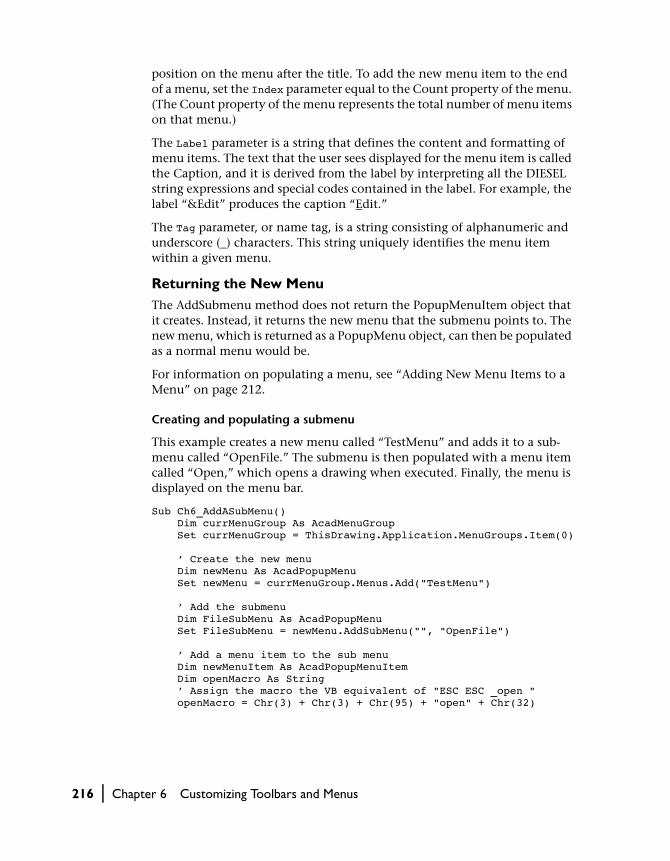
position on the menu after the title. To add the new menu item to the end of a menu, set the Index parameter equal to the Count property of the menu. (The Count property of the menu represents the total number of menu items on that menu.)
The Label parameter is a string that defines the content and formatting of menu items. The text that the user sees displayed for the menu item is called the Caption, and it is derived from the label by interpreting all the DIESEL string expressions and special codes contained in the label. For example, the label “&Edit” produces the caption “Edit.”
The Tag parameter, or name tag, is a string consisting of alphanumeric and underscore (_) characters. This string uniquely identifies the menu item within a given menu.
Returning the New MenuThe AddSubmenu method does not return the PopupMenuItem object that it creates. Instead, it returns the new menu that the submenu points to. The new menu, which is returned as a PopupMenu object, can then be populated as a normal menu would be.
For information on populating a menu, see “Adding New Menu Items to a Menu” on page 212.
Creating and populating a submenu
This example creates a new menu called “TestMenu” and adds it to a sub-menu called “OpenFile.” The submenu is then populated with a menu item called “Open,” which opens a drawing when executed. Finally, the menu is displayed on the menu bar.
Sub Ch6_AddASubMenu() Dim currMenuGroup As AcadMenuGroup Set currMenuGroup = ThisDrawing.Application.MenuGroups.Item(0) ’ Create the new menu Dim newMenu As AcadPopupMenu Set newMenu = currMenuGroup.Menus.Add("TestMenu") ’ Add the submenu Dim FileSubMenu As AcadPopupMenu Set FileSubMenu = newMenu.AddSubMenu("", "OpenFile") ’ Add a menu item to the sub menu Dim newMenuItem As AcadPopupMenuItem Dim openMacro As String ’ Assign the macro the VB equivalent of "ESC ESC _open " openMacro = Chr(3) + Chr(3) + Chr(95) + "open" + Chr(32)
216 | Chapter 6 Customizing Toolbars and Menus

Set newMenuItem = FileSubMenu.AddMenuItem _ (newMenu.count + 1, "Open", openMacro) ’ Display the menu on the menu bar newMenu.InsertInMenuBar _ (ThisDrawing.Application.menuBar.count + 1)End Sub
Deleting Menu Items from a Menu
To remove menu items from a menu, use the Delete method found on the menu item.
Deleting a menu item from a menu
This example adds a menu item to the end of the last menu displayed on the menu bar. It then deletes the menu item.
Sub Ch6_DeleteMenuItem() Dim LastMenu As AcadPopupMenu Set LastMenu = ThisDrawing.Application.menuBar. _ Item(ThisDrawing.Application.menuBar.count - 1) ’ Add a menu item Dim newMenuItem As AcadPopupMenuItem Dim openMacro As String ’ Assign the macro the VB equivalent of "ESC ESC _open " openMacro = Chr(3) + Chr(3) + Chr(95) + "open" + Chr(32) Set newMenuItem = LastMenu.AddMenuItem _ (LastMenu.count + 1, "Open", openMacro) ’ Remove the menu item from the menu newMenuItem.DeleteEnd Sub
Exploring the Properties of Menu Items
All menu items share the following properties:
TagA tag, or name tag, is a string consisting of alphanumeric and underscore (_) characters. This string uniquely identifies the menu item within a given menu. Tags identify the accelerator keys (keyboard key sequences) that cor-respond to the menu item.
You can read or write the value of a tag by using the Tag property.
Creating and Editing Pull-Down and Shortcut Menus | 217

LabelA label is a string that defines the content and formatting of menu items.
Menu item labels can contain DIESEL string expressions that conditionally alter the labels each time they are displayed. For more information on using DIESEL string expressions, see “DIESEL Expressions in Menus” on page 132 in the AutoCAD Customization Guide.
You can read or write the value of a label by using the Label property.
CaptionA caption is the text that the user sees displayed on the menu. This property is read-only and is derived from the Label property by removing any DIESEL string expressions.
You can read the value of a caption by using the Caption property.
MacroA macro is a series of commands that executes specific actions when a menu item is selected. Menu macros can simply be recordings of keystrokes that accomplish a task, or they can be a complex combination of commands, AutoLISP, DIESEL, or ActiveX programming code. For more information on menu macros, see “Menu Macros” on page 82 in the AutoCAD Customization Guide.
You can read or write the value of a menu macro by using the Macro property.
Help StringA help string is the text string that appears in the AutoCAD status line when a user highlights a menu item for selection.
You can read or write the value of a help string by using the HelpString property.
EnableUsing the Enable property you can enable or disable a menu item. You can also read the Enable property to determine if a menu item is currently enabled or disabled. Using this property to enable or disable a menu item overrides any setting for enabling in the DIESEL expression of the menu item.
See “Enabling and disabling menu items” on page 220 for an example of dis-abling menu items.
218 | Chapter 6 Customizing Toolbars and Menus

CheckUsing the Check property you can check or uncheck a menu item. You can also read the Check property to determine if a menu item is currently checked or unchecked. Using this property to check or uncheck a menu item overrides any setting for checking in the DIESEL expression of the menu item.
IndexThe index of a menu item specifies the position of that menu item on the menu on which it belongs. The index position of a menu always begins with position 0. For example, if the item is the first item on a menu, it returns an index position of 0. If it is the second item on a menu, it returns an index position of 1 and so on.
TypeYou can determine the type of a menu item by using the Type property. A menu item can be one of the following types: a regular menu, a separator, or the heading for a submenu. If the item is a regular menu item, this property returns acMenuItem. If the item is a separator, this property returns acMenuSeparator. If the item is a heading for a submenu, this property returns acSubMenu.
SubMenuYou can find the submenu by using the SubMenu property. If the menu item is of the type acSubMenu, this property returns the menu that is attached as the submenu, or embedded menu. The embedded menu is returned as a PopupMenu object.
If the menu item is not of the type acSubMenu, this property returns NULL.
ParentYou can find the menu to which a menu item belongs by using the Parent property. This property returns the menu on which the menu item resides. The parent menu is returned as a PopupMenu object.
Creating and Editing Pull-Down and Shortcut Menus | 219

Enabling and disabling menu items
This example creates a new menu called “TestMenu” and inserts two menu items. The second menu item is then disabled using the Enable property and the menu is displayed on the menu bar.
Sub Ch6_DisableMenuItem() Dim currMenuGroup As AcadMenuGroup Set currMenuGroup = ThisDrawing.Application.MenuGroups.Item(0) ’ Create the new menu Dim newMenu As AcadPopupMenu Set newMenu = currMenuGroup.Menus.Add("TestMenu") ’ Add two menu items and a menu separator to the new menu Dim MenuEnable As AcadPopupMenuItem Dim MenuDisable As AcadPopupMenuItem Dim MenuSeparator As AcadPopupMenuItem Dim openMacro As String ’ Assign the macro the VB equivalent of "ESC ESC _open " openMacro = Chr(3) + Chr(3) + Chr(95) + "open" + Chr(32) Set MenuEnable = newMenu.AddMenuItem _ (newMenu.count + 1, "OpenEnabled", openMacro) Set MenuSeparator = newMenu.AddSeparator("") Set MenuDisable = newMenu.AddMenuItem _ (newMenu.count + 1, "OpenDisabled", openMacro) ’ Disable the second menu item MenuDisable.Enable = False ’ Display the menu on the menu bar newMenu.InsertInMenuBar _ (ThisDrawing.Application.menuBar.count + 1)End Sub
220 | Chapter 6 Customizing Toolbars and Menus

Creating and Editing Toolbars
Using AutoCAD ActiveX/VBA you can create and edit toolbars within an existing menu group.
Creating New Toolbars
To create a new toolbar, use the Add method to add a new Toolbar object to the Toolbars collection.
Toolbar NameThe Add method requires as input the name of the toolbar to add. The name is a string of alphanumeric characters with no punctuation other than a dash (-) or an underscore (_). The name is the easiest way of identifying the toolbar within the collection.
You can change the name of a toolbar once it has been created. To change the name of an existing toolbar, use the Name property for that toolbar.
Creating a new toolbar
This example creates a new toolbar called “TestToolbar” in the first menu group in the MenuGroups collection.
Sub Ch6_CreateToolbar() Dim currMenuGroup As AcadMenuGroup Set currMenuGroup = ThisDrawing.Application.MenuGroups.Item(0) ’ Create the new toolbar Dim newToolbar As AcadToolbar Set newToolbar = currMenuGroup.Toolbars.Add("TestToolbar")End Sub
Adding New Toolbar Buttons to a Toolbar
To add a new toolbar button to a toolbar use the AddToolbarButton method. This method creates a new ToolbarItem object and adds it to the designated toolbar. You should only add buttons to a toolbar while the toolbar is visible.
The AddToolbarButton method takes five parameters as input: Index, Name, HelpString, Macro, and FlyoutButton.
IndexThe Index parameter is an integer that specifies the position of the new Tool-bar item within the toolbar. The index begins with position zero (0) as the first position on the toolbar after the title. To add the new toolbar button to
Creating and Editing Toolbars | 221

the end of a toolbar, set the Index parameter equal to the Count property of the toolbar. (The Count property of the toolbar represents the total number of toolbar buttons on that toolbar.)
Once a toolbar button has been created, you cannot change the index of the button through the Index property. To change the index of an existing tool-bar button, you must delete and re-add the toolbar button to a different posi-tion, or add or delete surrounding toolbar buttons until a proper placement is achieved.
NameA name is a string that identifies the toolbar button. The string must com-prise alphanumeric characters with no punctuation other than a dash (-) or an underscore (_). This string is displayed as the tooltip when the cursor is placed over the toolbar button.
Once a toolbar button has been created, you can change the name using the Name property.
Help StringA help string is the text string that appears in the AutoCAD status line when a user highlights a menu item for selection.
Once a toolbar button has been created, you can change the help string for the button using the HelpString property.
MacroA macro is a series of commands that executes specific actions when a toolbar button is selected. Toolbar macros can be simply recordings of keystrokes that accomplish a task, or they can be a complex combination of commands, AutoLISP, DIESEL, or ActiveX programming code. For more information on Toolbar macros, see “Menu Macros” on page 82 in the AutoCAD Customiza-tion Guide.
Once a Toolbar button has been created, you can change the macro for the button using the Macro property.
FlyoutButtonThe FlyoutButton parameter is an optional flag stating whether or not the new button is to be a flyout button. If the new button is to be a flyout button, this parameter must be set to TRUE. If the new button is not to be a flyout but-ton, this parameter can be set to FALSE or it can be ignored.
222 | Chapter 6 Customizing Toolbars and Menus
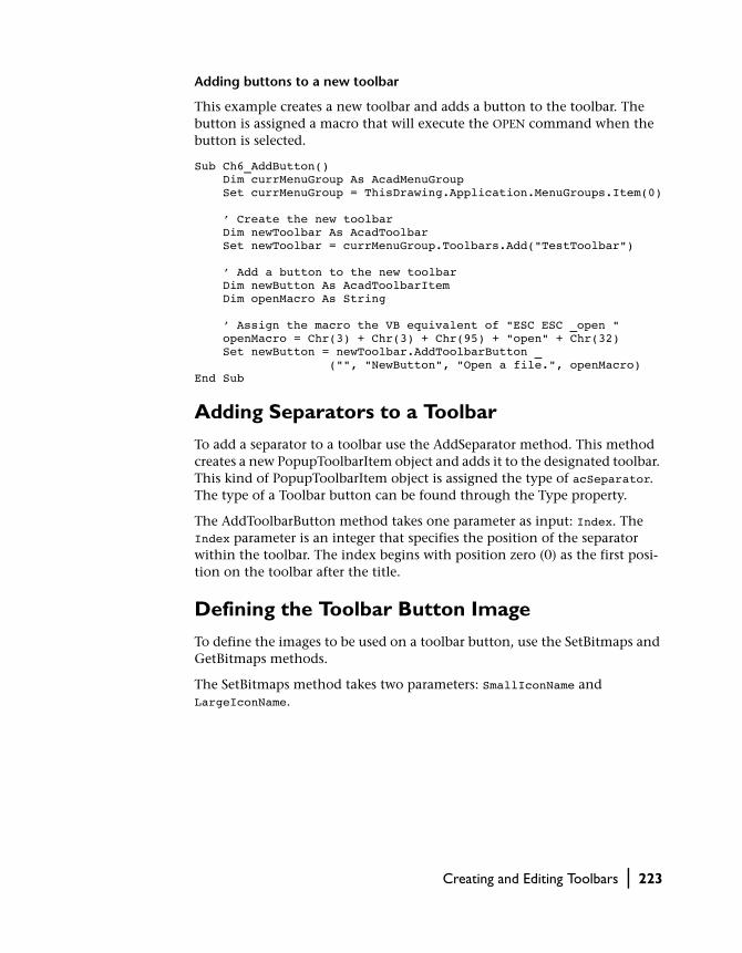
Adding buttons to a new toolbar
This example creates a new toolbar and adds a button to the toolbar. The button is assigned a macro that will execute the OPEN command when the button is selected.
Sub Ch6_AddButton() Dim currMenuGroup As AcadMenuGroup Set currMenuGroup = ThisDrawing.Application.MenuGroups.Item(0) ’ Create the new toolbar Dim newToolbar As AcadToolbar Set newToolbar = currMenuGroup.Toolbars.Add("TestToolbar") ’ Add a button to the new toolbar Dim newButton As AcadToolbarItem Dim openMacro As String ’ Assign the macro the VB equivalent of "ESC ESC _open " openMacro = Chr(3) + Chr(3) + Chr(95) + "open" + Chr(32) Set newButton = newToolbar.AddToolbarButton _ ("", "NewButton", "Open a file.", openMacro)End Sub
Adding Separators to a Toolbar
To add a separator to a toolbar use the AddSeparator method. This method creates a new PopupToolbarItem object and adds it to the designated toolbar. This kind of PopupToolbarItem object is assigned the type of acSeparator. The type of a Toolbar button can be found through the Type property.
The AddToolbarButton method takes one parameter as input: Index. The Index parameter is an integer that specifies the position of the separator within the toolbar. The index begins with position zero (0) as the first posi-tion on the toolbar after the title.
Defining the Toolbar Button Image
To define the images to be used on a toolbar button, use the SetBitmaps and GetBitmaps methods.
The SetBitmaps method takes two parameters: SmallIconName and LargeIconName.
Creating and Editing Toolbars | 223
SmallIconNameThe small icon name identifies the ID string of the small-image resource (16 x 15 bitmap). The string must comprise alphanumeric characters with no punctuation other than a dash (-) or an underscore (_), and should include the .bmp extension. The resource can be either a system bitmap or a user-defined bitmap. User-defined bitmaps must be of the appropriate size and must reside in the Support path.
LargeIconNameThe large icon name identifies the ID string of the large-image resource (24 x 22 bitmap). The string must comprise alphanumeric characters with no punctuation other than a dash (-) or an underscore (_), and should include the .bmp extension. The resource can be either a system bitmap or a user-defined bitmap. User-defined bitmaps must be of the appropriate size and must reside in the Support path.
Query an existing toolbar to find the name of the icons for the buttons
Sub Ch6_GetButtonImages() Dim Button As AcadToolbarItem Dim Toolbar0 As AcadToolbar Dim MenuGroup0 As AcadMenuGroup Dim SmallButtonName As String Dim LargeButtonName As String Dim msg As String Dim ButtonType As String ’ Get the first toolbar in the first menu group Set MenuGroup0 = ThisDrawing.Application. _ MenuGroups.Item(0) Set Toolbar0 = MenuGroup0.Toolbars.Item(0) ’ Clear the string variables SmallButtonName = "" LargeButtonName = "" ’ Create a header for the message box and ’ display the toolbar to be queried msg = "Toolbar: " + Toolbar0.Name + vbCrLf Toolbar0.Visible = True ’ Iterate through the toolbar and collect data ’ for each button in the toolbar. If the toolbar is ’ a normal button or a flyout, collect the small ’ and large button names for the button.
224 | Chapter 6 Customizing Toolbars and Menus
For Each Button In Toolbar0 ButtonType = Choose(Button.Type + 1, "Button", _ "Separator", "Control", "Flyout") msg = msg & ButtonType & ": " If Button.Type = acToolbarButton Or _ Button.Type = acToolbarFlyout Then Button.GetBitmaps SmallButtonName, _ LargeButtonName msg = msg + SmallButtonName + ", " _ + LargeButtonName End If msg = msg + vbCrLf Next Button ’ Display the results MsgBox msgEnd Sub
Creating Flyout Toolbars
To add a flyout toolbar button to a toolbar, use the AddToolbarButton method. This method creates a new ToolbarItem object and adds it to the designated toolbar.
The AddToolbarButton method takes five parameters as input: Index, Name, HelpString, Macro, and FlyoutButton. By setting the parameter Flyout to TRUE, the new button will be created as a flyout button. The return value from this method will be the new flyout toolbar. The flyout toolbar can then be populated as a normal toolbar would be.
For more information on populating a toolbar, see “Adding New Toolbar But-tons to a Toolbar” on page 221.
Creating a flyout toolbar button
This example creates two toolbars. The first toolbar contains a flyout button. The second toolbar is attached to the flyout button on the first toolbar.
Sub Ch6_AddFlyoutButton() Dim currMenuGroup As AcadMenuGroup Set currMenuGroup = ThisDrawing.Application. _ MenuGroups.Item(0) ’ Create the first toolbar Dim FirstToolbar As AcadToolbar Set FirstToolbar = currMenuGroup.Toolbars. _ Add("FirstToolbar")
Creating and Editing Toolbars | 225

’ Add a flyout button to the first menu on the menu bar Dim FlyoutButton As AcadToolbarItem Set FlyoutButton = FirstToolbar.AddToolbarButton _ ("", "Flyout", "Demonstrates a flyout button", _ "OPEN", True) ’ Create the second toolbar. This will be attached to ’ the first toolbar via the flyout button. Dim SecondToolbar As AcadToolbar Set SecondToolbar = currMenuGroup.Toolbars. _ Add("SecondToolbar") ’ Add a button to the next toolbar Dim newButton As AcadToolbarItem Dim openMacro As String ’ Assign the macro the VB equivalent of "ESC ESC _open " openMacro = Chr(3) + Chr(3) + Chr(95) + "open" + Chr(32) Set newButton = SecondToolbar.AddToolbarButton _ ("", "NewButton", "Open a file.", openMacro) ’ Attach the second toolbar to the flyout ’ button on the first toolbar FlyoutButton.AttachToolbarToFlyout currMenuGroup.Name, _ SecondToolbar.Name ’ Display the first toolbar, hide the second toolbar FirstToolbar.Visible = True SecondToolbar.Visible = FalseEnd Sub
Floating and Docking Toolbars
Toolbars can be docked or floated programmatically.
To float a toolbar, use the Float method for the toolbar. The Float method takes three parameters as input: Top, Left, and NumberFloatRows. The Top and Left parameters specify the pixel location for the top and left edge of the toolbar. The NumberFloatRows specifies the number of rows with which to create a horizontal toolbar. This number must be equal to or greater than one. The buttons of the toolbar will be distributed equally across the number of rows specified. For vertically aligned toolbars, this value specifies the num-ber of columns.
To dock a toolbar, use the Dock method for the toolbar. The Dock method takes three parameters as input: Side, Row, and Column. The Side parameter specifies the side of the toolbar that you will be positioning in the docking maneuver. You can specify the top, bottom, left, or right side of the toolbar. The Row and Column parameters specify a number on the existing rows and columns of docked toolbars at which to dock the toolbar.
226 | Chapter 6 Customizing Toolbars and Menus
You can query a toolbar to see if it is docked by using the Docked property. The Docked property will return TRUE if the toolbar is docked and FALSE if the toolbar is floating.
Docking a toolbar
This example creates a new toolbar with three buttons on it. The toolbar is then displayed and docked on the left side of the screen.
Sub Ch6_DockToolbar() Dim currMenuGroup As AcadMenuGroup Set currMenuGroup = ThisDrawing.Application. _ MenuGroups.Item(0) ’ Create the new toolbar Dim newToolbar As AcadToolbar Set newToolbar = currMenuGroup.Toolbars. _ Add("TestToolbar") ’ Add three buttons to the new toolbar. ’ All three buttons will have the same macro attached. Dim newButton1 As AcadToolbarItem Dim newButton2 As AcadToolbarItem Dim newButton3 As AcadToolbarItem Dim openMacro As String ’ Assign the macro the VB equivalent of "ESC ESC _open " openMacro = Chr(3) + Chr(3) + Chr(95) + "open" + Chr(32) Set newButton1 = newToolbar.AddToolbarButton _ ("", "NewButton1", "Open a file.", openMacro) Set newButton2 = newToolbar.AddToolbarButton _ ("", "NewButton2", "Open a file.", openMacro) Set newButton3 = newToolbar.AddToolbarButton _ ("", "NewButton3", "Open a file.", openMacro) ’ Display the toolbar newToolbar.Visible = True ’ Dock the toolbar to the left of the screen. newToolbar.Dock acToolbarDockLeftEnd Sub
Deleting Toolbar Buttons from a Toolbar
To remove toolbar buttons from a toolbar, use the Delete method found on the toolbar button. You should only delete buttons from a toolbar while the toolbar is visible.
Creating and Editing Toolbars | 227

Exploring the Properties of Toolbar Items
All toolbar items share the following properties:
TagA tag, or name tag, is a string consisting of alphanumeric and underscore (_) characters. This string uniquely identifies the toolbar item within a given toolbar. A new tag is assigned automatically when a toolbar item is created.
You can read or write the value of a tag by using the Tag property.
NameA name is a string identifying the toolbar item. It is also the string used for the tooltip text, which is the text string that pops up in AutoCAD when a user holds the mouse or another pointing device over the toolbar item.
You can read or write the value of a name by using the Name property.
MacroA macro is a series of commands that executes specific actions when a toolbar item is selected. Macros can simply be recordings of keystrokes that accom-plish a task, or they can be a complex combination of commands, AutoLISP, DIESEL, or ActiveX programming code. For more information on macros, see “Menu Macros” on page 82 in the AutoCAD Customization Guide.
You can read or write the value of a macro by using the Macro property.
Help StringA help string is the text string that appears in the AutoCAD status line for a toolbar button.
You can read or write the value of a help string by using the HelpString property.
IndexThe index of a toolbar item specifies the position of that toolbar item on the toolbar to which it belongs. The index position of a toolbar always begins with position 0. For example, if the item is the first item on a toolbar, it will have an index position of 0. If it is the second item on a toolbar, it will have an index position of 1, and so on.
You can read the index position of a toolbar item by using the Index prop-erty.
228 | Chapter 6 Customizing Toolbars and Menus

TypeA toolbar item can be one of the following types: a regular toolbar button, a separator, a flyout toolbar button, or a special control element. If the item is a regular toolbar button, this property returns acButton. If the item is a sep-arator, this property returns acToolButtonSeparator. If the item is a flyout button, this property returns acFlyout. If the item is a special control ele-ment, this property returns acControl.
You can determine the type of a toolbar item by using the Type property.
FlyoutIf the toolbar item is of the type acFlyout, this property returns the toolbar that is attached as the flyout toolbar. The flyout toolbar is returned as a Tool-bar object.
If the menu item is not of the type acFlyout, this property returns NULL.
You can find the flyout toolbar of a toolbar item by using the Flyout property.
ParentThis property returns the toolbar on which the toolbar item resides. The Par-ent toolbar is returned as a Toolbar object.
You can find the toolbar to which a toolbar item belongs by using the Parent property.
Toolbar PropertiesThere are other properties that apply to all toolbar items on the toolbar. Such properties include: whether the toolbar is docked or floating, visible or hid-den, and whether the toolbar uses large buttons or small buttons.
Creating Macros
A macro is a series of commands that executes specific actions when a toolbar item is selected. Macros can simply be recordings of keystrokes that accom-plish a task, or they can be a complex combination of commands, AutoLISP, DIESEL, or ActiveX programming code.
If you intend to include command parameters in a menu macro, you must know the sequence in which that command expects its parameters. Every character in a menu macro is significant, even the blank spaces. As AutoCAD is revised and enhanced, the sequence of prompts for various commands (and sometimes even the command names) might change. Therefore, your
Creating Macros | 229

custom menus might require minor changes when you upgrade to a new release of AutoCAD.
When command input comes from a menu item, the settings of the PICKADD and PICKAUTO system variables are assumed to be 1 and 0, respectively. This preserves compatibility with previous releases of AutoCAD and makes customization easier because you are not required to check the settings of these variables.
Macro Characters Mapped to ASCII Equivalents
The following table provides a synopsis of special characters used in menu macros and their equivalent ASCII numbers as they are used in VB and VBA. It is important always to use the ASCII equivalent for these special characters when creating the string for the Macro property.
Special characters used in menu and toolbar macros
Character ASCII equivalent Description
; chr(59) Issues ENTER
^M chr(94) + chr(77) Issues ENTER
^| chr(94) + chr(124) Issues TAB
SPACEBAR chr(32) Enters a space; blank space between command sequences in a menu item is equivalent to pressing the SPACEBAR
\ chr(92) Pauses for user input
_ chr(95) Translates AutoCAD commands and key words that follow
+ chr(43) Continues menu macro to the next line (if last character)
=* chr(61) + chr(42) Displays the current top-level image, pull-down, or shortcut menu
*^C^C chr(42) + chr(94) + chr(67)chr(94) + chr(67)
Prefix for a repeating item
$ chr(36) Loads a menu section or introduces a conditional DIESEL macro expression
230 | Chapter 6 Customizing Toolbars and Menus

Macro Termination
When a macro is executed, AutoCAD places a space at the end of the macro before processing the command sequence. AutoCAD processes the following menu macro as though you had entered line SPACEBAR.
line
^B chr(94) + chr(66) Toggles Snap on or off (CTRL+B)
^C chr(94) + chr(67) Cancels command (CTRL+C)
ESC Chr(3) Cancels command (ESC)
^D chr(94) + chr(68) Toggles Coords on or off (CTRL+D)
^E crh(94) + chr(69) Sets the next isometric plane (CTRL+E)
^G chr(94) + chr(71) Toggles Grid on or off (CTRL+G)
^H chr(94) + chr(72) Issues backspace
^O chr(94) + chr(79) Toggles Ortho on or off (CTRL+O)
^P chr(94) + chr(80) Toggles MENUECHO on or off
^Q chr(94) + chr(81) Echoes all prompts, status listings, and input to the printer (CTRL+Q)
^T chr(94) + chr(84) Toggles Tablet on or off (CTRL+T)
^V chr(94) + chr(86) Changes current viewport (CTRL+V)
^Z chr(94) + chr(90) Null character that suppresses the automatic addition of SPACEBAR at the end of a menu item
Special characters used in menu and toolbar macros (continued)
Character ASCII equivalent Description
Creating Macros | 231

Sometimes this is undesirable; for example, the TEXT or DIM command must be terminated by ENTER, not by a space. Also, it sometimes takes more than one space (or ENTER) to complete a command, but some text editors don’t let you create a line with trailing blanks. Two special conventions get around these problems.
■ When a semicolon (;) appears in a macro, AutoCAD substitutes an ENTER■ If a line ends with a control character, a backslash (\), a plus sign (+), or a
semicolon (;), AutoCAD does not add a blank after it
Look at the following macro:
erase \;
If this item simply ended with the backslash (which indicates user input), it would fail to complete the ERASE operation, because AutoCAD doesn’t add a blank after the backslash. Therefore, this macro uses a semicolon (;) to force an ENTER after the user input. Here are more examples:
ucs
ucs ;
text \.4 0 DRAFT Inc;;;Main St.;;;City, State;
Selecting the first macro enters ucs and SPACEBAR on the command line, and the following prompt appears:
Enter an option [New/Move/orthoGraphic/Prev/Restore/Save/Del/Apply/?/World] <World>:
Selecting the second macro enters ucs, SPACEBAR, and semicolon (;) at the command line, which accepts the default value, World. No difference between the first and second item would be evident on the screen; naturally, you wouldn’t put both on the same menu.
Selecting the third macro displays a prompt for a starting point and then draws the address on three lines. In the triple-semicolon (;;;), the first semicolon ends the text string, the second causes repetition of the TEXT com-mand, and the third calls for the default placement below the previous line.
NOTE All special characters must be input using their ASCII equivalents. For a list of ASCII equivalents, see “Macro Characters Mapped to ASCII Equivalents.”
232 | Chapter 6 Customizing Toolbars and Menus

Pausing for User Input
Sometimes it is useful to accept input from the keyboard or the pointing device in the midst of a macro by placing a backslash (\) at the point where you want input.
circle \1
layer off \;
The first macro pauses to ask the user for the center point and then reads a radius of 1 from the macro. Note that there is no space after the backslash character (\). The next macro pauses to ask the user to enter one layer name, then turns that layer off and exits the LAYER command. The LAYER command normally prompts for another operation and exits only if you press SPACEBAR (blank) or ENTER (;).
Normally, the macro resumes after one item is entered. Therefore, it isn’t pos-sible to construct a macro that accepts a variable number of inputs (as in object selection) and then continues. However, an exception is made for the SELECT command; a backslash suspends the macro until object selection has completed. For example, consider the following macro:
select \change previous ;properties color red ;
This macro uses the SELECT command to create a selection set of one or more objects. It then issues the CHANGE command, references this selection set using the Previous option, and changes the color of all selected objects to red.
Because the backslash character (\) causes a macro to pause for user input, you cannot use a backslash for any other purpose in a macro. When specifying file directory paths, use a forward slash (/) as the path delimiter: for example, /direct/file.
The following circumstances delay resumption of a macro:
■ If input of a point is expected, Object Snap modes may precede entry of the actual point
■ If X/Y/Z point filters are used, the macro remains suspended until the entire point has been accumulated
■ For the SELECT command only, the macro doesn’t resume until object selection has been completed
■ If the user responds with a transparent command, the suspended macro remains suspended until the transparent command is completed and the originally requested input is received
■ If the user responds by choosing another macro (to supply options or to execute a transparent command), the original macro is suspended, and
Creating Macros | 233

the newly selected item is processed to completion before the suspended macro is resumed
Canceling a Command
To make sure you have no previous incomplete commands, use ^C^C in a macro. This is the same as pressing ESC twice from the keyboard. Although a single ^C cancels most commands, ^C^C is required to return to the Com-mand prompt from a DIM command. Therefore, ̂ C^C ensures that AutoCAD returns to the Command prompt in most cases.
Macro Repetition
Once you have selected a command, you are likely to use it several times before moving on to another command. That is how most people use tools; you pick up a tool, do several things with it, then pick up another tool, and so on. To avoid picking up the tool before each use, AutoCAD provides a command repetition capability, triggered by a null response. However, you cannot use this feature to specify command options.
This feature makes it possible for you to repeat frequently used commands until you choose another command. If a macro begins with *^C^C immedi-ately following the item label, the macro is saved in memory. Subsequent Command prompts are answered by that macro until it is terminated by ESC or by the selection of another macro.
Do not use ^C (Cancel) within a macro that begins with the string *^C^C; this cancels the macro repetition.
The following is an example of the repetitive, or modal, approach to com-mand handling.
*^C^CMOVE Single
*^C^CCOPY Single
*^C^CERASE Single
*^C^CSTRETCH Single Crossing
*^C^CROTATE Single
*^C^CSCALE Single
Macro repetition does not work for items in image tile menus.
234 | Chapter 6 Customizing Toolbars and Menus

Use of Single Object Selection Mode
Single object selection puts object selection in single selection mode, disables the normal dialog conducted by object selection, and causes the selection to return the first object(s) selected by a subsequent option. This can be quite handy in a macro. For example, consider the following macro:
*^C^CERASE single
This macro terminates the current command and activates the ERASE com-mand with the single selection option. After you select this item, you either point to the single object to be erased or point to a blank area and specify a window. The object(s) selected in this way are erased, and the macro is repeated (due to the leading asterisk) so that you can erase something else. Single selection mode leads to more dynamic interaction with AutoCAD.
Creating Status-Line Help for Menu Items and Toolbar Items
Status-line help messages are an important aspect of native help support. These are the simple, descriptive messages that appear in the status line when a menu or toolbar item is highlighted. The status-line help for all menu and toolbar items is contained in the HelpString property for that item.
The HelpString property is empty when the menu or toolbar item is first cre-ated.
Adding status-line help to a menu item
This example creates a new menu called “TestMenu” and then creates a menu item called “Open.” The menu item is then assigned status-line help via the HelpString property.
Sub Ch6_AddHelp() Dim currMenuGroup As AcadMenuGroup Set currMenuGroup = ThisDrawing.Application.MenuGroups.Item(0) ’ Create the new menu Dim newMenu As AcadPopupMenu Set newMenu = currMenuGroup.Menus.Add _ ("Te" + Chr(Asc("&")) + "stMenu")
Creating Status-Line Help for Menu Items and Toolbar Items | 235
’ Add a menu item to the new menu Dim newMenuItem As AcadPopupMenuItem Dim openMacro As String ’ Assign the macro the VBA equivalent of "ESC ESC _open " openMacro = Chr(3) + Chr(3) + Chr(95) + "open" + Chr(32) ’ Create the menu item Set newMenuItem = newMenu.AddMenuItem _ (newMenu.count + 1, Chr(Asc("&")) _ + "Open", openMacro) ’ Add the status line help to the menu item newMenuItem.HelpString = "Opens an AutoCAD drawing file." ’ Display the menu on the menu bar newMenu.InsertInMenuBar _ (ThisDrawing.Application.menuBar.count + 1)End Sub
Adding Entries to the Right-Click Menu
The right-click menu, or shortcut menu, is a special menu included in the AutoCAD base menu group. This menu appears when the user holds SHIFT and clicks the right mouse button.
AutoCAD finds the shortcut menu by looking in the base menu group for a menu with the ShortcutMenu property equal to TRUE. You can add new menu items to the shortcut menu by following the steps listed in “Adding New Menu Items to a Menu” on page 212.
New menu groups may or may not have a shortcut menu available. To create a shortcut menu for a menu group, follow the guidelines listed in “Creating New Menus” on page 211, and use POP0 as the label for the new menu.
236 | Chapter 6 Customizing Toolbars and Menus

Adding a menu item to the end of the right-click menu
This example adds the menu item “OpenDWG” to the end of the right-click menu.
Sub Ch6_AddMenuItemToshortcutMenu() Dim currMenuGroup As AcadMenuGroup Set currMenuGroup = ThisDrawing.Application.MenuGroups.Item(0) ’ Find the shortcut menu and assign it to the ’ shortcutMenu variable Dim scMenu As AcadPopupMenu Dim entry As AcadPopupMenu For Each entry In currMenuGroup.Menus If entry.shortcutMenu = True Then Set scMenu = entry End If Next entry ’ Add a menu item to the shortcut menu Dim newMenuItem As AcadPopupMenuItem Dim openMacro As String ’ Assign the macro the VBA equivalent of "ESC ESC _open " openMacro = Chr(3) + Chr(3) + Chr(95) + "open" + Chr(32) Set newMenuItem = scMenu.AddMenuItem _ ("", Chr(Asc("&")) _ + "OpenDWG", openMacro)End Sub
Adding Entries to the Right-Click Menu | 237

238

In This Chapter
Using Events
7■ Understanding the Events in
AutoCAD
■ Guidelines for Writing Event Handlers
■ Handling Application Level Events
■ Handling Document Level Events
■ Handling Object Level Events
Events are notifications, or messages, that are sent out
by AutoCAD to inform you about the current state of
the session, or alert you that something has happened.
For example, when a drawing is opened the BeginOpen
event is triggered. This event contains the name of the
AutoCAD drawing that was opened. There is another
event triggered when a drawing is closed. Given this
information you could write a subroutine, or event han-
dler, that uses these events to track the amount of time
a user spends working on a particular drawing.
239
Understanding the Events in AutoCAD
There are three types of events in AutoCAD:
■ Application level events respond to changes in the AutoCAD application and its environment. These events respond to the opening, saving, closing and printing of drawings, creation of new drawings, issuing of AutoCAD commands, loading or unloading of ARX and LISP applications, changes to system variables, and changes to the Application window
■ Document level events respond to the changes of a specific document or its contents. These events respond to the addition, deletion, or modifica-tion of objects, activation of a shortcut menu, changes in the pickfirst selection set, changes to the Drawing window, and regeneration of the drawing. There are also document level events for the opening, closing, and printing of a drawing, and the loading or unloading of ARX and LISP applications from the drawing
■ Object level events respond to the changes of a specific object. Currently there is only one object level event. It is triggered whenever an object is modified
Subroutines that respond to events are called event handlers and are exe-cuted automatically each and every time their designated event is triggered. Information contained in events, such as the drawing name in the BeginOpen event, are passed to event handlers through parameters.
Guidelines for Writing Event Handlers
It is important to remember that events simply provide information on the state or activities taking place within AutoCAD. Although event handlers can be written to respond to those events, AutoCAD is often in the middle of pro-cessing commands when the event handler is triggered. Event handlers, therefore, have some restrictions on what they can do if they are to provide safe operations in conjunction with AutoCAD and its database.
■ Do not rely on the sequence of events
When writing event handlers, do not rely on the sequence of events to happen in the exact order you think they occur. For example, if you issue an OPEN command, the events BeginCommand, BeginOpen, EndOpen, and EndCommand will all be triggered. However, they may not occur in that order. The only event sequence you can safely rely on is that a Begin event will occur before the corresponding End event. In the previous
240 | Chapter 7 Using Events

example, the events may get triggered in the following order: BeginCom-mand, BeginOpen, EndCommand, and EndOpen, or even BeginCom-mand, EndCommand, BeginOpen, and EndOpen.
■ Do not rely on the sequence of operations
If you delete object1 and then object2, do not rely on the fact that you will receive the ObjectErased event for object1 and then for object2. You may receive the ObjectErased event for object2 first.
■ Do not attempt any interactive functions from an event handler
Attempting to execute interactive functions from within an event handler can cause serious problems, as AutoCAD may still be processing a com-mand at the time the event is triggered. Therefore, you should always avoid the use of input-acquisition methods such as GetPoint, GetEntity, GetKeyword, and so on, as well as selection set operations and the Send-Command method from within event handlers.
■ Do not launch a dialog box from within an event handler
Dialog boxes are considered interactive functions and can interfere with the current operation of AutoCAD. However, message boxes and alert boxes are not considered interactive and can be issued safely.
■ You can write data to any object in the database, except the object that issued the event
Obviously any object causing an event to be triggered could still be open for use with AutoCAD and the operation currently in progress. Therefore, avoid writing any information to an object from an event handler for the same object. However, you can safely read information from the object triggering an event. For example, suppose you have a floor that is filled with tiles and you create an event handler attached to the border of the floor. If you change the size of the floor, the event handler will automati-cally add or subtract tiles to fill the new area. The event handler will be able to read the new area of the border, but it cannot attempt any changes on the border itself.
■ Do not perform any action from an event handler that will trigger the same event
If you perform the same action in an event handler that triggers that same event, you will create an infinite loop. For example, you should never attempt to open a drawing from within the BeginOpen event, or AutoCAD will simply continue to open more drawings until the maxi-mum number of open drawings is reached.
■ Remember that no events will be fired while AutoCAD is displaying a modal dialog
Guidelines for Writing Event Handlers | 241

Handling Application Level Events
Application level events are not persistent in AutoCAD VBA. That is, they are not automatically enabled when a VBA project is loaded. Application level events must therefore be enabled for VBA and all other ActiveX Automation controllers.
Once the application level events are enabled, you have a wide range of events available to you. These events include
AppActivate Triggered just before the main Application window is activated.
AppDeactivate Triggered just before the main Application window is deactivated.
ARXLoaded Triggered when an ObjectARX application has been loaded.
ARXUnloaded Triggered when an ObjectARX application has been unloaded.
BeginCommand Triggered immediately after a command is issued, but before it completes.
BeginFileDrop Triggered when a file is dropped on the main Application window.
BeginLISP Triggered immediately after AutoCAD receives a request to evaluate a LISP expression.
BeginModal Triggered just before a modal dialog box is displayed.
BeginOpen Triggered immediately after AutoCAD receives a request to open an existing drawing.
BeginPlot Triggered immediately after AutoCAD receives a request to print a drawing.
BeginQuit Triggered just before an AutoCAD session ends.
BeginSave Triggered immediately after AutoCAD receives a request to save the drawing.
EndCommand Triggered immediately after a command completes.
EndLISP Triggered upon completion of evaluating a LISP expression.
EndModal Triggered just after a modal dialog box is dismissed.
242 | Chapter 7 Using Events

EndOpen Triggered immediately after AutoCAD finishes opening an existing drawing.
EndPlot Triggered after a document has been sent to the printer.
EndSave Triggered when AutoCAD has finished saving the drawing.
LISPCancelled Triggered when the evaluation of a LISP expression is cancelled.
NewDrawing Triggered just before a new drawing is created.
SysVarChanged Triggered when the value of a system variable is changed.
WindowChanged
Triggered when there is a change to the Application window.
WindowMovedOrResized
Triggered just after the Application window has been moved or resized.
Enabling Application Level Events
Before you can use application level events you must create a new class mod-ule and declare an object of type AcadApplication with events. For example, assume that a new class module is created and called EventClassModule. The new class module contains the declaration of the application with the VBA keyword WithEvents.
To create a new class and declare an Application object with events:
1 In the VBA IDE, insert a class module. From the Insert menu, choose Class Module.
2 Select the new class module in the Project window.
3 Change the name of the class in the Properties window to EventClassMod-ule.
4 Open the Code window for the class using F7, or by selecting the menu option View ➤ Code.
5 In the Code window for the class, add the following line:
Public WithEvents App As AcadApplication
After the new object has been declared with events, it appears in the Object drop-down list box in the class module, and you can write event procedures
Handling Application Level Events | 243

for the new object in the class module. (When you select the new object in the Object box, the valid events for that object are listed in the Procedure drop-down list box.)
Before the procedures will run, however, you must connect the declared object in the class module with the Application object. You can do this with the following code from any module.
To connect the declared object to the Application object:
1 In the Code window for your main module, add the following line to the dec-larations section:
Dim X As New EventClassModule
2 In the same window, add the following subroutine:
Sub InitializeEvents() Set X.App = ThisDrawing.ApplicationEnd Sub
3 In the code for your main module, add a call to the InitializeApp subroutine:
Call InitializeEvents
Once the InitializeEvents procedure has been run, the App object in the class module points to the Application object specified, and any event procedures in the class module will run when the events occur.
Prompting to continue when a drawing is dropped into AutoCAD
This example intercepts the load process when a file has been dragged and dropped into AutoCAD. A message box containing the name of the file that was dropped and Yes/No/Continue buttons that allow the user to decide if the file should continue to be loaded display. If the user chooses to cancel out of the operation, that decision is returned through the Cancel parameter of the BeginFileDrop event and the file is not loaded.
Public WithEvents ACADApp As AcadApplication
Sub Example_AcadApplication_Events() ’ This example intializes the public variable (ACADApp) ’ which will be used to intercept AcadApplication Events ’ ’ Run this procedure FIRST! ’ We could get the application from the ThisDocument ’ object, but that would require having a drawing open, ’ so we grab it from the system. Set ACADApp = GetObject(, "AutoCAD.Application")End Sub
244 | Chapter 7 Using Events

Private Sub ACADApp_BeginFileDrop _ (ByVal FileName As String, Cancel As Boolean) ’ This example intercepts an Application BeginFileDrop event. ’ ’ This event is triggered when a drawing file is dragged ’ into AutoCAD. ’ ’ To trigger this example event: ’ 1) Make sure to run the example that initializes ’ the public variable (named ACADApp) linked to this event. ’ ’ 2) Drag an AutoCAD drawing file into the AutoCAD ’ application from either the Windows Desktop ’ or Windows Explorer
’ Use the "Cancel" variable to stop the loading of the ’ dragged file, and the "FileName" variable to notifiy ’ the user which file is about to be dragged in.
If MsgBox("AutoCAD is about to load " & FileName & vbCrLf _ & "Do you want to continue loading this file?", _ vbYesNoCancel + vbQuestion) <> vbYes Then Cancel = True End IfEnd Sub
Handling Document Level Events
Document level events are persistent in AutoCAD VBA. That is, they are auto-matically enabled when a VBA project is loaded. However, they are not enabled for any other controller, such as VB. Document level events must therefore be enabled for all other ActiveX Automation controllers.
Once the document level events are enabled, you have a wide range of events available to you. These events include
Activate Triggered when a Document window is activated.
BeginClose Triggered just before a document is closed.
BeginCommand Triggered immediately after a command is issued, but before it completes.
BeginDoubleClick
Triggered after the user double-clicks on an object in the drawing.
BeginLISP Triggered immediately after AutoCAD receives a request to evaluate a LISP expression.
Handling Document Level Events | 245

BeginPlot Triggered immediately after AutoCAD receives a request to print a drawing.
BeginRightClick Triggered after the user right-clicks on the Drawing window.
BeginSave Triggered immediately after AutoCAD receives a request to save the drawing.
BeginShortcutMenuCommand
Triggered after the user right-clicks on the Drawing window, and before the shortcut menu appears in Command mode.
BeginShortcutMenuDefault
Triggered after the user right-clicks on the Drawing window, and before the shortcut menu appears in Default mode.
BeginShortcutMenuEdit
Triggered after the user right-clicks on the Drawing window, and before the shortcut menu appears in Edit mode.
BeginShortcutMenuGrip
Triggered after the user right-clicks on the Drawing window, and before the shortcut menu appears in Grip mode.
BeginShortcutMenuOsnap
Triggered after the user right-clicks on the Drawing window, and before the shortcut menu appears in Osnap mode.
Deactivate Triggered when the Drawing window is deactivated.
EndCommand Triggered immediately after a command completes.
EndLISP Triggered upon completion of evaluating a LISP expression.
246 | Chapter 7 Using Events

EndPlot Triggered after a document has been sent to the printer.
EndSave Triggered when AutoCAD has finished saving the drawing.
EndShortcutMenu
Triggered after the shortcut menu appears.
LayoutSwitched Triggered after the user switches to a different layout.
LISPCancelled Triggered when the evaluation of a LISP expression is cancelled.
ObjectAdded Triggered when an object has been added to the drawing.
ObjectErased Triggered when an object has been erased from the drawing.
ObjectModified Triggered when an object in the drawing has been modified.
SelectionChanged
Triggered when the current pickfirst selection set changes.
WindowChanged
Triggered when there is a change to the Document window.
WindowMovedOrResized
Triggered just after the Drawing window has been moved or resized.
Enabling Document Level Events in Environments Other Than VBA
Before you can use document level events in VB or another environment besides VBA, you must create a new class module and declare an object of type AcadDocument with events. For example, assume a new class module is created and called EventClassModule. The new class module contains the declaration of the application with the VBA keyword WithEvents.
Handling Document Level Events | 247

To create a new class and declare a Document object with events:
1 In the VBA IDE, insert a class module. From the Insert menu, choose Class Module.
2 Select the new class module in the Project window.
3 Change the name of the class in the Properties window to EventClassMod-ule.
4 Open the Code window for the class using F7, or by selecting the menu option View ➤ Code.
5 In the Code window for the class, add the following line:
Public WithEvents Doc As AcadDocument
After the new object has been declared with events, it appears in the Object drop-down list box in the class module, and you can write event procedures for the new object in the class module. (When you select the new object in the Object box, the valid events for that object are listed in the Procedure drop-down list box.)
Before the procedures will run, however, you must connect the declared object in the class module with the Document object. You can do this with the following code from any module.
To connect the declared object to the Document object:
1 In the Code window for your main module, add the following line to the dec-larations section:
Dim X As New EventClassModule
2 In the same window, add the following subroutine:
Sub InitializeEvents() Set X.Doc = ThisDrawingEnd Sub
3 In the code for your main module, add a call to the InitializeApp subroutine:
Call InitializeEvents
Once the InitializeEvents procedure has been run, the Doc object in the class module points to the Document object created, and any event procedures in the class module will run when the events occur.
Coding Document Level Events in Environments Other Than VBA
Once the document level events have been enabled, you will find the Doc class variable available from the Object drop-down list of the Class Module
248 | Chapter 7 Using Events

Code window. Select the Doc class and the list of available events will appear in the Procedure drop-down list. Simply select the event you want to write a handler for and the handler skeleton is created automatically.
Coding Document Level Events in VBA
As mentioned in “Handling Document Events,” document level events are automatically enabled when a VBA project is loaded. To write event handlers for document level events in VBA, you simply select AcadDocument from the Object drop-down list in the Code window. The available events for the doc-ument will appear in the Procedure drop-down list. Simply select the event you want to write a handler for and the handler skeleton is created automat-ically.
Note that event handlers created in this fashion apply to the current active drawing. To create event handlers for a specific drawing, first follow the steps listed in “Enabling Document Level Events in Environments Other Than VBA” on page 247. This will allow you to enable a specific document for events.
Updating the shortcut menu at the BeginShortcutMenuDefault and End-ShortcutMenu events
This example uses the event handler for the BeginShortcutMenuDefault event to add the “OpenDWG” menu item to the beginning of the shortcut menu. Then the event handler for the EndShortcutMenu event removes the additional menu item so that it is not saved permanently in the user’s menu configuration.
Private Sub AcadDocument_BeginShortcutMenuDefault _ (ShortcutMenu As AutoCAD.IAcadPopupMenu) On Error Resume Next ’ Add a menu item to the cursor menu Dim newMenuItem As AcadPopupMenuItem Dim openMacro As String openMacro = Chr(27) + Chr(27) + Chr(95) + "open" + Chr(32) Set newMenuItem = ShortcutMenu.AddMenuItem _ (0, Chr(Asc("&")) _ + "OpenDWG", openMacro)End Sub
Private Sub AcadDocument_EndShortcutMenu _ (ShortcutMenu As AutoCAD.IAcadPopupMenu) On Error Resume Next ShortcutMenu.Item("OpenDWG").DeleteEnd Sub
Handling Document Level Events | 249

Handling Object Level Events
The object level events is not persistent in AutoCAD VBA. That is, it is not automatically enabled when a VBA project is loaded. An object level event must be enabled for VBA and all other ActiveX Automation controllers.
Once the object level events is enabled, you have the following event avail-able to you:
Modified Triggered when an object in the drawing has been modified.
Enabling the Object Level Event
Before you can use object level events you must create a new class module and declare an object of type AcadObject with events. For example, assume that a new class module is created and called EventClassModule. The new class module contains the declaration of the application with the VBA key-word WithEvents.
To create a new class and declare a Circle object with events:
1 In the VBA IDE, insert a class module. From the Insert menu, choose Class Module.
2 Select the new class module in the Project window.
3 Change the name of the class in the Properties window to EventClassMod-ule.
4 Open the Code window for the class using F7, or by selecting the menu option View ➤ Code.
5 In the Code window for the class, add the following line:
Public WithEvents Object As AcadCircle
After the new object has been declared with events, it appears in the Object drop-down list box in the class module, and you can write event procedures for the new object in the class module. (When you select the new object in the Object box, the valid events for that object are listed in the Procedure drop-down list box.)
Before the procedures will run, however, you must connect the declared object in the class module with the Circle object. You can do this with the following code from any module.
250 | Chapter 7 Using Events

To connect the declared object to the Automation object:
1 In the Code window for your main module, add the following line to the dec-larations section:
Dim X As New EventClassModule
2 In the same window, create a circle called “MyCircle” and initialize it as con-taining events:
Sub InitializeEvents() Dim MyCircle As AcadCircle Dim centerPoint(0 To 2) As Double Dim radius As Double centerPoint(0) = 0#: centerPoint(1) = 0#: centerPoint(2) = 0# radius = 5# Set MyCircle = ThisDrawing.ModelSpace.AddCircle(centerPoint, radius) Set X.Object = MyCircleEnd Sub
3 In the code for your main module, add a call to the InitializeApp subroutine:
Call InitializeEvents
Once the InitializeEvents procedure has been run, the Circle object in the class module points to the Circle object created, and any event procedures in the class module will run when the events occur.
NOTE When coding in VBA, you must provide an event handler for all objects enabled for the Modified event. If you do not provide a handler, VBA may termi-nate unexpectedly.
Displaying the area of a closed polyline whenever the polyline is updated
This example creates a lightweight polyline with events. The event handler for the polyline then displays the new area whenever the polyline is changed. To trigger the event, simply change the size of the polyline in AutoCAD. Remember you must run the CreatePLineWithEvents subroutine before the event handler is activated.
Handling Object Level Events | 251

Public WithEvents PLine As AcadLWPolyline
Sub CreatePLineWithEvents() ’ This example creates a light weight polyline Dim points(0 To 9) As Double points(0) = 1: points(1) = 1 points(2) = 1: points(3) = 2 points(4) = 2: points(5) = 2 points(6) = 3: points(7) = 3 points(8) = 3: points(9) = 2 Set PLine = ThisDrawing.ModelSpace. _ AddLightWeightPolyline(points) PLine.Closed = True ThisDrawing.Application.ZoomAllEnd Sub
Private Sub PLine_Modified _ (ByVal pObject As AutoCAD.IAcadObject) ’ This event is triggered when the polyline is resized. ’ If the polyline is deleted the modified event is still ’ triggered, so we use the error handler to avoid ’ reading data from a deleted object. On Error GoTo ERRORHANDLER MsgBox "The area of " & pObject.ObjectName & " is: " _ & pObject.Area Exit Sub ERRORHANDLER: MsgBox Err.DescriptionEnd Sub
252 | Chapter 7 Using Events

In This ChapterIn This Chapter
Working in Three-Dimensional Space
8■ Specifying 3D Coordinates
■ Defining a User Coordinate System
■ Converting Coordinates
■ Creating 3D Objects
■ Editing in 3D
■ Mirroring in 3D
Most drawings consist of two-dimensional (2D) views of
objects that are three-dimensional (3D). Though this
method of drafting is widely used in the architectural
and engineering communities, it is limited: the draw-
ings are 2D representations of 3D objects and must be
visually interpreted. Moreover, because the views are
created independently, there are more possibilities for
error and ambiguity. As a result, you may want to create
true 3D models instead of 2D representations. You can
use the AutoCAD drawing tools to create detailed, real-
istic 3D objects and manipulate them in various ways.
253

Specifying 3D Coordinates
Specifying 3D coordinates is the same as specifying 2D coordinates with the addition of a third dimension, the Z axis. When drawing in 3D, you specify X, Y, and Z values of the coordinates in either the world coordinate system (WCS) or the user coordinate system (UCS). The following illustration shows the X, Y, and Z axes of the WCS:
The Right-Hand Rule
The right-hand rule determines the positive axis direction of the Z axis when you know the direction of the X and Y axes in a 3D coordinate system. The right-hand rule also determines the positive rotation direction about an axis in 3D space.
-X +Z +Y
+X-Y
WCS origin point
-Z
(0, 0, 0) origin
UCS icon
Y
XZ
254 | Chapter 8 Working in Three-Dimensional Space

To determine the positive axis direction of the X, Y, and Z axes, place the back of your right hand near the screen. Point your thumb in the direction of the positive X axis. Extend your index and middle fingers as illustrated and point your index finger in the direction of the positive Y axis. Your middle finger indicates the direction of the positive Z axis. To determine the positive rota-tion direction about an axis, point your right thumb in the positive direction of the axis and curl your fingers as illustrated. Your fingers indicate the posi-tive rotation direction about the axis.
Entering X, Y, Z Coordinates
Entering 3D WCS coordinates is similar to entering 2D WCS coordinates. In addition to specifying X and Y values, you specify a Z value. As with the 2D coordinates, a variant is used to pass the coordinates to ActiveX methods and properties, and to query the coordinates.
The following subroutine first creates a 2D lightweight polyline with three vertices, then creates a 3D polyline with three vertices. Notice the length of the array containing the vertices is expanded to include the Z coordinates in the creation of the 3D polyline. The subroutine finishes by querying the coordinates in both polylines and displaying the coordinates in a message box.
Defining and querying the coordinates for 2D and 3D polylines
This example creates two polylines, each with three coordinates. The first polyline is a 2D polyline, the second polyline is 3D. The example then queries the coordinates of the polylines and displays the coordinates in a message box.
Sub Ch8_Polyline_2D_3D() Dim pline2DObj As AcadLWPolyline Dim pline3DObj As AcadPolyline Dim points2D(0 To 5) As Double Dim points3D(0 To 8) As Double ’ Define three 2D polyline points points2D(0) = 1: points2D(1) = 1 points2D(2) = 1: points2D(3) = 2 points2D(4) = 2: points2D(5) = 2 ’ Define three 3D polyline points points3D(0) = 1: points3D(1) = 1: points3D(2) = 0 points3D(3) = 2: points3D(4) = 1: points3D(5) = 0 points3D(6) = 2: points3D(7) = 2: points3D(8) = 0
Specifying 3D Coordinates | 255

’ Create the 2D light weight Polyline Set pline2DObj = ThisDrawing.ModelSpace. _ AddLightWeightPolyline(points2D) pline2DObj.Color = acRed pline2DObj.Update ’ Create the 3D polyline Set pline3DObj = ThisDrawing.ModelSpace. _ AddPolyline(points3D) pline3DObj.Color = acBlue pline3DObj.Update ’ Query the coordinates of the polylines Dim get2Dpts As Variant Dim get3Dpts As Variant get2Dpts = pline2DObj.Coordinates get3Dpts = pline3DObj.Coordinates ’ Display the coordinates MsgBox ("2D polyline (red): " & vbCrLf & _ get2Dpts(0) & ", " & get2Dpts(1) & vbCrLf & _ get2Dpts(2) & ", " & get2Dpts(3) & vbCrLf & _ get2Dpts(4) & ", " & get2Dpts(5)) MsgBox ("3D polyline (blue): " & vbCrLf & _ get3Dpts(0) & ", " & get3Dpts(1) & ", " & _ get3Dpts(2) & vbCrLf & _ get3Dpts(3) & ", " & get3Dpts(4) & ", " & _ get3Dpts(5) & vbCrLf & _ get3Dpts(6) & ", " & get3Dpts(7) & ", " & _ get3Dpts(8))End Sub
Defining a User Coordinate System
You define a user coordinate system (UCS) object to change the location of the (0, 0, 0) origin point and the orientation of the XY plane and Z axis. You can locate and orient a UCS anywhere in 3D space, and you can define, save, and recall as many user coordinate systems as you require. Coordinate input and display are relative to the current UCS. If multiple viewports are active, they share the same UCS.
If you plan to work extensively in 3D, you can define several user coordinate systems, each having a different origin and orientation for various construc-tion requirements.
256 | Chapter 8 Working in Three-Dimensional Space

To indicate the origin and orientation of the UCS, you can display the UCS icon at the UCS origin point using the UCSIconAtOrigin property. If the UCS icon is turned on (see the UCSIconOn property) and is not displayed at the origin, it is displayed at the WCS coordinate defined by the UCSORG system variable.
UCSs are especially useful in 3D. You may find it easier to align the coordi-nate system with existing geometry than to figure out the exact placement of a 3D point.
You can define a new UCS in paper space just as you can in model space; however, the UCSs in paper space are restricted to 2D manipulation. AutoCAD keeps track of the last ten coordinate systems created in model space and the last ten in paper space.
You can create a new user coordinate system using the Add method. This method requires four values as input: the coordinate of the origin, a coordi-nate on the X and Y axes, and the name of the UCS.
All coordinates in the AutoCAD ActiveX Automation are entered in the world coordinate system (WCS). Use the GetUCSMatrix method to return the transformation matrix of a given UCS. Use this transformation matrix to find the equivalent WCS coordinates.
(0, 0, 0) origin
UCS icon
first UCS second UCS model with two UCSs
Defining a User Coordinate System | 257

To make a UCS active, use the ActiveUCS property on the Document object. If changes are made to the active UCS, the new UCS object must be reset as the active UCS for the changes to appear. To reset the active UCS, simply call the ActiveUCS property again with the updated UCS object.
Creating a new UCS, making it active, and translating the coordinates of a point into the UCS coordinates
The following subroutine creates a new UCS and sets it as the active UCS for the drawing. It then asks the user to pick a point in the drawing, and returns both WCS and UCS coordinates for the point.
Sub Ch8_NewUCS() ’ Define the variables we will need Dim ucsObj As AcadUCS Dim origin(0 To 2) As Double Dim xAxisPnt(0 To 2) As Double Dim yAxisPnt(0 To 2) As Double ’ Define the UCS points origin(0) = 4: origin(1) = 5: origin(2) = 3 xAxisPnt(0) = 5: xAxisPnt(1) = 5: xAxisPnt(2) = 3 yAxisPnt(0) = 4: yAxisPnt(1) = 6: yAxisPnt(2) = 3 ’ Add the UCS to the ’ UserCoordinatesSystems collection Set ucsObj = ThisDrawing.UserCoordinateSystems. _ Add(origin, xAxisPnt, yAxisPnt, "New_UCS") ’ Display the UCS icon ThisDrawing.ActiveViewport.UCSIconAtOrigin = True ThisDrawing.ActiveViewport.UCSIconOn = True ’ Make the new UCS the active UCS ThisDrawing.ActiveUCS = ucsObj MsgBox "The current UCS is : " & ThisDrawing.ActiveUCS.Name _ & vbCrLf & " Pick a point in the drawing." ’ Find the WCS and UCS coordinate of a point Dim WCSPnt As Variant Dim UCSPnt As Variant WCSPnt = ThisDrawing.Utility.GetPoint(, "Enter a point: ") UCSPnt = ThisDrawing.Utility.TranslateCoordinates _ (WCSPnt, acWorld, acUCS, False) MsgBox "The WCS coordinates are: " & WCSPnt(0) & ", " _ & WCSPnt(1) & ", " & WCSPnt(2) & vbCrLf & _ "The UCS coordinates are: " & UCSPnt(0) & ", " _ & UCSPnt(1) & ", " & UCSPnt(2)End Sub
258 | Chapter 8 Working in Three-Dimensional Space

Converting Coordinates
The TranslateCoordinates method translates a point or a displacement from one coordinate system to another. A point argument, called OriginalPoint, can be interpreted as either a 3D point or a 3D displacement vector. This argument is distinguished by the Boolean argument, Disp. If the Disp argu-ment is set to TRUE the OriginalPoint argument is treated as a displacement vector; otherwise, it is treated as a point. Two more arguments determine which coordinate system the OriginalPoint is from, and to which coordi-nate system the OriginalPoint is to be converted. The following AutoCAD coordinate systems can be specified in the From and To arguments:
■ WCS
World Coordinate System—the reference coordinate system. All other coordinate systems are defined relative to the WCS, which never changes. Values measured relative to the WCS are stable across changes to other coordinate systems. All points passed in and out of ActiveX methods and properties are expressed in the WCS unless otherwise specified.
■ UCS
User Coordinate System—the working coordinate system. The user speci-fies a UCS to make drawing tasks easier. All points passed to AutoCAD commands, including those returned from AutoLISP routines and exter-nal functions, are points in the current UCS (unless the user precedes them with an * at the Command prompt). If you want your application to send coordinates in the WCS, OCS, or DCS to AutoCAD commands, you must first convert them to the UCS by calling the TranslateCoordinates method.
■ OCS
Object Coordinate System—point values specified by certain methods and properties for the Polyline and LightweightPolyline objects are expressed in this coordinate system, relative to the object. These points are usually converted into the WCS, current UCS, or current DCS, according to the intended use of the object. Conversely, points in WCS, UCS, or DCS must be translated into an OCS before they are written to the database by means of the same properties. See the AutoCAD ActiveX and VBA Reference for the methods and properties that use this coordinate system.
When converting coordinates to or from the OCS you must enter the nor-mal for the OCS in the final argument of the TranslateCoordinates func-tion.
Converting Coordinates | 259

■ DCS
Display Coordinate System—the coordinate system where objects are transformed before they are displayed. The origin of the DCS is the point stored in the AutoCAD system variable TARGET, and its Z axis is the view-ing direction. In other words, a viewport is always a plan view of its DCS. These coordinates can be used to determine where something will be dis-played to the AutoCAD user.
■ PSDCS
Paper Space DCS—this coordinate system can be transformed only to or from the DCS of the currently active model space viewport. This is essen-tially a 2D transformation, where the X and Y coordinates are always scaled and offset if the Disp argument is FALSE. The Z coordinate is scaled but never translated. Therefore, it can be used to find the scale factor between the two coordinate systems. The PSDCS can be transformed only into the current model space viewport. If the from argument equals PSDCS, then the to argument must equal DCS, and vice versa.
Translating OCS coordinates to WCS coordinates
This example creates a polyline in model space. The first vertex for the polyline is then displayed in both the OCS and WCS coordinates. The con-version from OCS to WCS requires the normal for the OCS be placed in the last argument of the TranslateCoordinates method.
Sub Ch8_TranslateCoordinates() ’ Create a polyline in model space. Dim plineObj As AcadPolyline Dim points(0 To 14) As Double ’ Define the 2D polyline points points(0) = 1: points(1) = 1: points(2) = 0 points(3) = 1: points(4) = 2: points(5) = 0 points(6) = 2: points(7) = 2: points(8) = 0 points(9) = 3: points(10) = 2: points(11) = 0 points(12) = 4: points(13) = 4: points(14) = 0 ’ Create a light weight Polyline object in model space Set plineObj = ThisDrawing.ModelSpace.AddPolyline(points) ’ Find the X and Y coordinates of the ’ first vertex of the polyline Dim firstVertex As Variant firstVertex = plineObj.Coordinate(0) ’ Find the Z coordinate for the polyline ’ using the elevation property firstVertex(2) = plineObj.Elevation
260 | Chapter 8 Working in Three-Dimensional Space

’ Change the normal for the pline so that the ’ difference between the coordinate systems ’ is obvious. Dim plineNormal(0 To 2) As Double plineNormal(0) = 0# plineNormal(1) = 1# plineNormal(2) = 2# plineObj.Normal = plineNormal ’ Translate the OCS coordinate into WCS Dim coordinateWCS As Variant coordinateWCS = ThisDrawing.Utility.TranslateCoordinates _ (firstVertex, acOCS, acWorld, False, plineNormal) ’ Display the coordinates of the point MsgBox "The first vertex has the following coordinates:" _ & vbCrLf & "OCS: " & firstVertex(0) & ", " & _ firstVertex(1) & ", " & firstVertex(2) & vbCrLf & _ "WCS: " & coordinateWCS(0) & ", " & _ coordinateWCS(1) & ", " & coordinateWCS(2)End Sub
Creating 3D Objects
AutoCAD supports three types of 3D modeling: wireframe, surface, and solid. Each type has its own creation and editing techniques.
A wireframe model is a skeletal description of a 3D object. There are no sur-faces in a wireframe model; it consists only of points, lines, and curves that describe the edges of the object. You can create wireframe models by posi-tioning 2D (planar) objects anywhere in 3D space. AutoCAD also provides some 3D wireframe objects, such as 3D polylines. Because each object that makes up a wireframe model must be independently drawn and positioned, this type of modeling can often be the most time-consuming.
wireframe
Creating 3D Objects | 261

Surface modeling is more sophisticated than wireframe modeling in that it defines not only the edges of a 3D object, but also its surfaces. The AutoCAD surface modeler defines faceted surfaces using a polygonal mesh. Because the faces of the mesh are planar, the mesh can only approximate curved surfaces.
Solid modeling is the easiest type of 3D modeling to use. With the AutoCAD solid modeler, you can make 3D objects by creating basic 3D shapes: box, cone, cylinder, sphere, wedge, and torus (donut). You then combine these shapes to create more complex solids by joining or subtracting them or find-ing their intersecting (overlapping) volume. You can also create solids by sweeping a 2D object along a path or revolving it about an axis. With AutoCAD Designer, you can also define solids parametrically and maintain associativity between 3D models and the 2D views that you generate from them.
WARNING! Because each modeling type uses a different method for con-structing 3D models, and editing methods vary in their effect on the different model types, it is recommended that you not mix modeling methods. Limited conversion between model types is available from solids to surfaces and from surfaces to wireframes; however, you cannot convert from wireframes to surfaces or from surfaces to solids.
mesh
solid
262 | Chapter 8 Working in Three-Dimensional Space

Creating Wireframes
With AutoCAD you can create wireframe models by positioning any 2D pla-nar object anywhere in 3D space. You can position 2D objects in 3D space using several methods:
■ Creating the object by entering 3D points. You enter a coordinate that defines the X, Y, and Z location of the point
■ Setting the default construction plane (XY plane) on which you will draw the object by defining a UCS
■ Moving the object to its proper orientation in 3D space after you create it
Also, you can create some wireframe objects, such as polylines, that can exist in all three dimensions. Use the Add3DPoly method to create 3D polylines. The following illustration is an example of a 3D modeling application using a combination of 3D polylines and 2D symbology positioned in 3D space.
Creating Meshes
A rectangular mesh (PolygonMesh object) represents an object’s surface using planar facets. The mesh density, or number of facets, is defined in terms of a matrix of M and N vertices, similar to a grid consisting of columns and rows. M and N specify the column and row position, respectively, of any given ver-tex. You can create meshes in both 2D and 3D, but they are used primarily for 3D.
Creating 3D Objects | 263

Use meshes if you don’t need the level of detail about physical properties (that is, mass, weight, center of gravity, and so forth) that solids provide but you do need the hiding, shading, and rendering capabilities that wireframes don’t provide. Meshes are also useful if you want to create geometry with unusual mesh patterns, such as a 3D topographical model of a mountainous terrain.
A mesh can be open or closed. A mesh is open in a given direction if the start and end edges of the mesh do not touch, as shown in the following illustra-tions:
Use the Add3DMesh method for creating rectangular meshes. This method takes three values as input: the number of vertices in the M direction, the numer of vertices in the N direction, and a variant array containing coordi-nates for all the vertices in the mesh.
Once the PolygonMesh is created, use the MClose and NClose properties to close the mesh.
M openN open
M closedN open
M openN closed
M closedN closed
264 | Chapter 8 Working in Three-Dimensional Space

Creating a polygon mesh
This example creates a 4 x 4 polygon mesh. The direction of the active view-port is then adjusted so that the three-dimensional nature of the mesh is more easily viewed.
Sub Ch8_Create3DMesh() Dim meshObj As AcadPolygonMesh Dim mSize, nSize, Count As Integer Dim points(0 To 47) As Double ’ create the matrix of points points(0) = 0: points(1) = 0: points(2) = 0 points(3) = 2: points(4) = 0: points(5) = 1 points(6) = 4: points(7) = 0: points(8) = 0 points(9) = 6: points(10) = 0: points(11) = 1 points(12) = 0: points(13) = 2: points(14) = 0 points(15) = 2: points(16) = 2: points(17) = 1 points(18) = 4: points(19) = 2: points(20) = 0 points(21) = 6: points(22) = 2: points(23) = 1 points(24) = 0: points(25) = 4: points(26) = 0 points(27) = 2: points(28) = 4: points(29) = 1 points(30) = 4: points(31) = 4: points(32) = 0 points(33) = 6: points(34) = 4: points(35) = 0 points(36) = 0: points(37) = 6: points(38) = 0 points(39) = 2: points(40) = 6: points(41) = 1 points(42) = 4: points(43) = 6: points(44) = 0 points(45) = 6: points(46) = 6: points(47) = 0 mSize = 4: nSize = 4 ’ creates a 3Dmesh in model space Set meshObj = ThisDrawing.ModelSpace. _ Add3DMesh(mSize, nSize, points) ’ Change the viewing direction of the viewport ’ to better see the cylinder Dim NewDirection(0 To 2) As Double NewDirection(0) = -1 NewDirection(1) = -1 NewDirection(2) = 1 ThisDrawing.ActiveViewport.direction = NewDirection ThisDrawing.ActiveViewport = ThisDrawing.ActiveViewport ZoomAllEnd Sub
Creating a Polyface Mesh
Use the AddPolyfaceMesh method to create a polyface mesh, with each face capable of having numerous vertices.
Creating 3D Objects | 265

Creating a polyface mesh is similar to creating a rectangular mesh. To create a polyface mesh, specify coordinates for all its vertices then define each face by entering vertex numbers for all the vertices of that face. As you create the polyface mesh, you can set specific edges to be invisible, assign them to lay-ers, or give them colors.
To make an edge invisible, enter the vertex number for the edge as a negative value. For more information on creating polyface meshes, see the AddPoly-faceMesh method of the ActiveX and VBA Reference.
Creating a polyface mesh
This example creates a Polyface Mesh object in model space. The viewing direction of the active viewport is updated to display the three-dimensional nature of the mesh more easily.
Sub Ch8_CreatePolyfaceMesh() ’Define the mesh vertices Dim vertex(0 To 17) As Double vertex(0) = 4: vertex(1) = 7: vertex(2) = 0 vertex(3) = 5: vertex(4) = 7: vertex(5) = 0 vertex(6) = 6: vertex(7) = 7: vertex(8) = 0 vertex(9) = 4: vertex(10) = 6: vertex(11) = 0 vertex(12) = 5: vertex(13) = 6: vertex(14) = 0 vertex(15) = 6: vertex(16) = 6: vertex(17) = 1 ’ Define the face list Dim FaceList(0 To 7) As Integer FaceList(0) = 1 FaceList(1) = 2 FaceList(2) = 5 FaceList(3) = 4 FaceList(4) = 2 FaceList(5) = 3 FaceList(6) = 6 FaceList(7) = 5 ’ Create the polyface mesh Dim polyfaceMeshObj As AcadPolyfaceMesh Set polyfaceMeshObj = ModelSpace.AddPolyfaceMesh _ (vertex, FaceList) ’ Change the viewing direction of the viewport to ’ better see the polyface mesh Dim NewDirection(0 To 2) As Double NewDirection(0) = -1 NewDirection(1) = -1 NewDirection(2) = 1 ThisDrawing.ActiveViewport.direction = NewDirection ThisDrawing.ActiveViewport = ThisDrawing.ActiveViewport ZoomAllEnd Sub
266 | Chapter 8 Working in Three-Dimensional Space
Creating Solids
A solid object (3DSolid object) represents the entire volume of an object. Sol-ids are the most informationally complete and least ambiguous of the 3D modeling types. Complex solid shapes are also easier to construct and edit than wireframes and meshes.
You create solids from one of the basic solid shapes of box, cone, cylinder, sphere, torus, and wedge or by extruding a 2D object along a path or revolving a 2D object about an axis. Use one of the following methods to create solids:
AddBox, AddCone, AddCylinder, AddEllipticalCone, AddEllipticalCylinder, AddExtrudedSolid, AddExtrudedSolidAlongPath, AddRevolvedSolid, AddSolid, AddSphere, AddTorus, or AddWedge.
Creating a wedge solid
This example creates a wedge-shaped solid in model space. The viewing direction of the active viewport is updated to display the three-dimensional nature of the wedge more easily.
Sub Ch8_CreateWedge() Dim wedgeObj As Acad3DSolid Dim center(0 To 2) As Double Dim length As Double Dim width As Double Dim height As Double ’ Define the wedge center(0) = 5#: center(1) = 5#: center(2) = 0 length = 10#: width = 15#: height = 20# ’ Create the wedge in model space Set wedgeObj = ThisDrawing.ModelSpace. _ AddWedge(center, length, width, height) ’ Change the viewing direction of the viewport Dim NewDirection(0 To 2) As Double NewDirection(0) = -1 NewDirection(1) = -1 NewDirection(2) = 1 ThisDrawing.ActiveViewport.direction = NewDirection ThisDrawing.ActiveViewport = ThisDrawing.ActiveViewport ZoomAllEnd Sub
Creating 3D Objects | 267
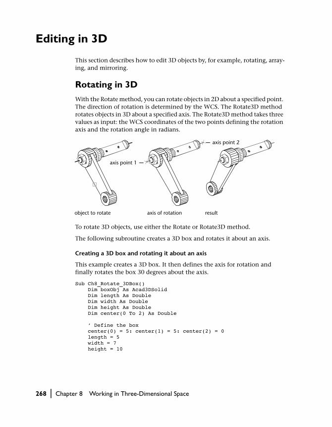
Editing in 3D
This section describes how to edit 3D objects by, for example, rotating, array-ing, and mirroring.
Rotating in 3D
With the Rotate method, you can rotate objects in 2D about a specified point. The direction of rotation is determined by the WCS. The Rotate3D method rotates objects in 3D about a specified axis. The Rotate3D method takes three values as input: the WCS coordinates of the two points defining the rotation axis and the rotation angle in radians.
To rotate 3D objects, use either the Rotate or Rotate3D method.
The following subroutine creates a 3D box and rotates it about an axis.
Creating a 3D box and rotating it about an axis
This example creates a 3D box. It then defines the axis for rotation and finally rotates the box 30 degrees about the axis.
Sub Ch8_Rotate_3DBox() Dim boxObj As Acad3DSolid Dim length As Double Dim width As Double Dim height As Double Dim center(0 To 2) As Double ’ Define the box center(0) = 5: center(1) = 5: center(2) = 0 length = 5 width = 7 height = 10
object to rotate axis of rotation result
axis point 2
axis point 1
268 | Chapter 8 Working in Three-Dimensional Space

’ Create the box object in model space Set boxObj = ThisDrawing.ModelSpace. _ AddBox(center, length, width, height) ’ Define the rotation axis with two points Dim rotatePt1(0 To 2) As Double Dim rotatePt2(0 To 2) As Double Dim rotateAngle As Double rotatePt1(0) = -3: rotatePt1(1) = 4: rotatePt1(2) = 0 rotatePt2(0) = -3: rotatePt2(1) = -4: rotatePt2(2) = 0 rotateAngle = 30 rotateAngle = rotateAngle * 3.141592 / 180# ’ Rotate the box boxObj.Rotate3D rotatePt1, rotatePt2, rotateAngle ZoomAll End Sub
Arraying in 3D
With the ArrayRectangular method, you can create a rectangular array in 3D. In addition to specifying the number of columns (X direction) and rows (Y direction), you also specify the number of levels (Z direction).
resultobject to be arrayed
Editing in 3D | 269

Creating a 3D rectangular array
This example creates a circle and then uses that circle to create a rectangular array of 4 rows, 4 columns, and 3 levels of circles.
Sub Ch8_CreateRectangularArray() ’ Create the circle Dim circleObj As AcadCircle Dim center(0 To 2) As Double Dim radius As Double center(0) = 2: center(1) = 2: center(2) = 0 radius = 0.5 Set circleObj = ThisDrawing.ModelSpace. _ AddCircle(center, radius) ’ Define the rectangular array Dim numberOfRows As Long Dim numberOfColumns As Long Dim numberOfLevels As Long Dim distanceBwtnRows As Double Dim distanceBwtnColumns As Double Dim distanceBwtnLevels As Double numberOfRows = 4 numberOfColumns = 4 numberOfLevels = 3 distanceBwtnRows = 1 distanceBwtnColumns = 1 distanceBwtnLevels = 4 ’ Create the array of objects Dim retObj As Variant retObj = circleObj.ArrayRectangular _ (numberOfRows, numberOfColumns, _ numberOfLevels, distanceBwtnRows, _ distanceBwtnColumns, distanceBwtnLevels) ZoomAllEnd Sub
270 | Chapter 8 Working in Three-Dimensional Space

Mirroring in 3D
With the Mirror3D method, you can mirror objects along a specified mirror-ing plane specified by three points.
Mirroring in 3D
This example creates a box in model space. It then mirrors the box about a plane and colors the mirrored box red.
Sub Ch8_MirrorABox3D() ’ Create the box object Dim boxObj As Acad3DSolid Dim length As Double Dim width As Double Dim height As Double Dim center(0 To 2) As Double center(0) = 5#: center(1) = 5#: center(2) = 0 length = 5#: width = 7: height = 10# ’ Create the box (3DSolid) object in model space Set boxObj = ThisDrawing.ModelSpace. _ AddBox(center, length, width, height) ’ Define the mirroring plane with three points Dim mirrorPt1(0 To 2) As Double Dim mirrorPt2(0 To 2) As Double Dim mirrorPt3(0 To 2) As Double mirrorPt1(0) = 1.25: mirrorPt1(1) = 0: mirrorPt1(2) = 0 mirrorPt2(0) = 1.25: mirrorPt2(1) = 2: mirrorPt2(2) = 0 mirrorPt3(0) = 1.25: mirrorPt3(1) = 2: mirrorPt3(2) = 2 ’ Mirror the box Dim mirrorBoxObj As Acad3DSolid Set mirrorBoxObj = boxObj.Mirror3D _ (mirrorPt1, mirrorPt2, mirrorPt3) mirrorBoxObj.Color = acRed ZoomAllEnd Sub
object to mirror defining a mirror plane result
12
3
Editing in 3D | 271
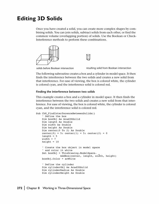
Editing 3D Solids
Once you have created a solid, you can create more complex shapes by com-bining solids. You can join solids, subtract solids from each other, or find the common volume (overlapping portion) of solids. Use the Boolean or Check-Interference methods to perform these combinations.
The following subroutine creates a box and a cylinder in model space. It then finds the interference between the two solids and creates a new solid from that interference. For ease of viewing, the box is colored white, the cylinder is colored cyan, and the interference solid is colored red.
Finding the interference between two solids
This example creates a box and a cylinder in model space. It then finds the interference between the two solids and creates a new solid from that inter-ference. For ease of viewing, the box is colored white, the cylinder is colored cyan, and the interference solid is colored red.
Sub Ch8_FindInterferenceBetweenSolids() ’ Define the box Dim boxObj As Acad3DSolid Dim length As Double Dim width As Double Dim height As Double Dim center(0 To 2) As Double center(0) = 5: center(1) = 5: center(2) = 0 length = 5 width = 7 height = 10 ’ Create the box object in model space ’ and color it white Set boxObj = ThisDrawing.ModelSpace. _ AddBox(center, length, width, height) boxObj.Color = acWhite ’ Define the cylinder Dim cylinderObj As Acad3DSolid Dim cylinderRadius As Double Dim cylinderHeight As Double
solids before Boolean intersection resulting solid from Boolean intersection
272 | Chapter 8 Working in Three-Dimensional Space

center(0) = 0: center(1) = 0: center(2) = 0 cylinderRadius = 5 cylinderHeight = 20 ’ Create the Cylinder and ’ color it cyan Set cylinderObj = ThisDrawing.ModelSpace.AddCylinder _ (center, cylinderRadius, cylinderHeight) cylinderObj.Color = acCyan ’ Find the interference between the two solids ’ and create a new solid from it. Color the ’ new solid red. Dim solidObj As Acad3DSolid Set solidObj = boxObj.CheckInterference(cylinderObj, True) solidObj.Color = acRed ZoomAllEnd Sub
Solids are further modified by obtaining the 2D cross section of a solid or slic-ing a solid into two pieces. Use the SectionSolid method to find cross sections of solids, and the SliceSolid method for slicing a solid into two pieces.
three points define the cutting plane
cutting plane cross section isolated and hatched for clarity
1
2
3
three points define the cutting plane
one half retained both halves retained
1
2
3
Editing 3D Solids | 273

Slicing a solid into two solids
This example creates a box in model space. It then slices the box based on a plane defined by three points. The slice is returned as a 3DSolid.
Sub Ch8_SliceABox() ’ Create the box object Dim boxObj As Acad3DSolid Dim length As Double Dim width As Double Dim height As Double Dim center(0 To 2) As Double center(0) = 5#: center(1) = 5#: center(2) = 0 length = 5#: width = 7: height = 10# ’ Create the box (3DSolid) object in model space Set boxObj = ThisDrawing.ModelSpace. _ AddBox(center, length, width, height) boxObj.Color = acWhite ’ Define the section plane with three points Dim slicePt1(0 To 2) As Double Dim slicePt2(0 To 2) As Double Dim slicePt3(0 To 2) As Double slicePt1(0) = 1.5: slicePt1(1) = 7.5: slicePt1(2) = 0 slicePt2(0) = 1.5: slicePt2(1) = 7.5: slicePt2(2) = 10 slicePt3(0) = 8.5: slicePt3(1) = 2.5: slicePt3(2) = 10 ’ slice the box and color the new solid red Dim sliceObj As Acad3DSolid Set sliceObj = boxObj.SliceSolid _ (slicePt1, slicePt2, slicePt3, True) sliceObj.Color = acRed ZoomAllEnd Sub
Like meshes, solids are displayed as wireframes until you hide, shade, or render them. Additionally, you can analyze solids for their mass properties (volume, moments of inertia, center of gravity, and so forth). Use the following properties to analyze solids: MomentOfInertia, PrincipalDirections, PrincipalMoments, ProductOfInertia, RadiiOfGyration, and Volume.
The ContourlinesPerSurface property controls the number of tessellation lines used to visualize curved portions of the wireframe. The RenderSmoothness property adjusts the smoothness of shaded and hidden-line objects.
274 | Chapter 8 Working in Three-Dimensional Space
In This ChapterIn This Chapter
Defining Layouts and Plotting
9■ Understanding Model Space and
Paper Space
■ Understanding Layouts
■ Understanding Viewports
■ Plotting Your Drawing
After you’ve created your drawing with AutoCAD, you
usually plot it on paper. A plotted drawing can contain
a single view of your drawing or a more complex
arrangement of views. In paper space, you can create
windows called floating viewports, which display vari-
ous views of the drawing. Depending on your needs,
you can plot one or more viewports, or set options that
determine what is plotted and how the image fits on the
paper.
275

Understanding Model Space and Paper Space
Model space is the drawing environment in which you create the geometry for your model. Normally, as you begin to draw in model space, you designate your drawing limits to determine the extents of the drawing environment, and you draw in real world units.
Paper space represents the paper representation of your model as it will be plotted. In paper space you can lay out different views of your drawing, scale views independently from one another, and arrange the different views of your drawing as you want them to be plotted. There can be many different paper space representations of your drawing.
Understanding Layouts
All the geometry of your drawing is contained in layouts. Model space geom-etry is contained on a single layout named Model. You cannot rename the model space layout, nor can you create another model space layout. There can be only one model space layout per drawing.
Paper space geometry is also contained on layouts. You can have many different paper space layouts in your drawing, each representing a different configuration to print. You can change the name of the paper layouts.
In ActiveX Automation the ModelSpace object contains all the geometry in the model space layout. Because there can be more than one paper space lay-out in a drawing, the PaperSpace object points to the last active paper space layout.
Understanding the Relationship between Layouts and Blocks
The content of any layout is distributed among two different ActiveX objects: the Layout object and the Block object. The Layout object contains the plot settings and the visual properties of the layout as it appears in the AutoCAD user interface. The Block object contains the geometry for the layout.
276 | Chapter 9 Defining Layouts and Plotting
Each Layout object is associated with one, and only one, Block object. To access the Block object associated with a given layout, use the Block property. Conversely, each Block object is associated with one, and only one, Layout object. To access the Layout object associated with a given Block, use the Lay-out property for that block.
Understanding Plot Configurations
A PlotConfiguration object is similar to a Layout object, as both contain identical plot information. The difference is that a Layout object is associated with a Block object containing the geometry to plot. A PlotConfiguration object is not associated with a particular Block object. It is simply a named collection of plot settings available for use with any geometry.
Determining Layout Settings
Layout settings control the final plotted output. These settings affect the paper size, plot scale, plot area, plot origin, and the plot device name. Under-standing how to use layout settings ensures the layout plots as expected. All the settings for a layout can be changed from the Layout object properties and methods.
Selecting a Paper Size and UnitsThe choice of paper size depends on the plotter configured for your system. Each different plotter will have a standard list of available paper sizes. You can change the paper size for a layout by using the CanonicalMedia-Name property.
You can also specify the units for your layout using the PaperUnits property. This property takes one of three values: acInches, acMillimeters, or acPixels. If your plotter is configured for raster output, you must specify the output size in pixels.
Adjusting the Plot OriginThe plot origin is the lower-left corner of the specified plotted area and is controlled with the PlotOrigin property. Typically, the plot origin is set to (0, 0). However, you can center the plot on the sheet of paper by setting the CenterPlot property to TRUE. Centering the plot alters the plot origin.
Understanding Layouts | 277

Setting the Plot AreaWhen you prepare to plot a layout, you can specify the plot area to determine what will be included in the plot. To specify the plot area, use the PlotType property. This property requires one of the following values as input:
acDisplay Prints everything that is in the current model space display. This option is unavailable when plotting from a paper space layout.
acExtents Prints everything that falls within the boundaries of the currently selected space.
acLimits Prints everything that is in the limits of the current space.
acView Prints the view named by the ViewToPlot property.
acWindow Prints everything in the window specified by the SetWindowToPlot method.
acLayout Prints everything that falls within the margins of the specified paper size. This option is not available when printing from model space.
When you create a new paper space layout, the default option is acLayout.
Setting the Plot ScaleGenerally, you draw objects at their actual size. When you plot the drawing, you can either specify a precise scale or fit the image to the paper. To specify a scale, enter either a standard or custom plot scale.
To enter a standard scale, first set the UseStandardScale property to TRUE. You can then enter the desired scale using the StandardScale property.
To enter a custom scale, first set the UseStandardScale property to FALSE. You can then enter the custom scale using the SetCustomScale method.
When you are reviewing an early draft view, a precise scale is not always important. You can use the acScaleToFit value of the StandardScale prop-erty to plot the layout at the largest possible size that fits the paper.
Setting the Lineweight ScaleLineweights can be scaled proportionately in a layout with the plot scale. Typically, lineweights specify the linewidth of plotted objects and are plotted with the linewidth size regardless of the plot scale. Most often, you use the default plot scale of 1:1 when plotting a layout. However, if you want to plot an E-size layout that is scaled to fit on an A-size sheet of paper, for example, you can specify lineweights to be scaled in proportion to the new plot scale.
278 | Chapter 9 Defining Layouts and Plotting

To scale lineweights, set the ScaleLineweights property to TRUE. If you do not want lineweights to be scaled, set this property to FALSE.
Setting the Plot DeviceThe plot device name is specified in the ConfigName property. You can set this name to any valid device name for your system. If you do not set this property, plots will be sent to the default device for your system.
Understanding Viewports
When working in model space you draw geometry in tile viewports (referred to as Viewport objects in ActiveX Automation). You can display one or several different viewports at a time. If several tiled viewports are displayed, editing in one viewport affects all other viewports. However, you can set magnification, viewpoint, grid, and snap settings individually for each viewport.
In paper space, you work in floating paper space viewports (referred to as PViewport objects in ActiveX Automation) to contain different views of your model. Floating viewports are treated as objects you can move, resize, and shape to create a suitable layout. You also can draw objects, such as title blocks or annotations, directly in the paper space view without affecting the model itself.
You cannot edit the model in paper space. To access the model in a PViewport object, toggle from paper space to model space using the ActiveSpace property. As a result, you can work with the model while keeping the overall layout visible. In PViewport objects, the editing and view-changing capabilities are almost the same as in Viewport objects. However, you have more control over the individual views. For example, you can freeze or turn off layers in some viewports without affecting others. You can turn an entire
tiled viewports floating viewports
Understanding Viewports | 279

viewport display on or off. You can also align views between viewports and scale the views relative to the overall layout.
The following illustration shows how different views of a model are dis-played in paper space. Each paper space image represents a PViewport object with a different view. In one view, the dimensioning layer is frozen. Notice that the title block, border, and annotation, which are drawn in paper space, do not appear in the Model Space view. Also, the layer containing the view-port borders has been turned off.
When you work in a Viewport object, the ActiveSpace property must always be set to acModelSpace. When you are working in a PViewport object, you can set the ActiveSpace property to either acModelSpace or acPaperSpace, thus allowing you to switch between paper space and model space as needed.
In AutoCAD ActiveX Automation, the ActiveSpace property is used to control the TILEMODE system variable. Setting ThisDrawing.ActiveSpace = acModelSpace is equivalent to setting TILEMODE = on, and setting
PViewport object, Viewport object, and ActiveSpace property settings
Type of viewport Status Usage
PViewport ActiveSpace = acPaperspace
Arrange the layout by creating floating viewports and adding title block, borders, and annotation. Editing does not affect the model.
PViewport ActiveSpace = acModelspace
Work within floating viewports to edit the model or change views. You can turn off or freeze layers in individual viewports.
Viewport ActiveSpace = acModelspace
Split the screen into tiled viewports to edit different views of the model.
the model the model displayed in floating viewports
280 | Chapter 9 Defining Layouts and Plotting
ThisDrawing.ActiveSpace = acPaperSpace is equivalent to setting TILEMODE = off.
Similarly, the MSpace property is the equivalent of both the MSPACE and PSPACE commands in AutoCAD. Setting ThisDrawing.MSpace = TRUE is the same as using the MSPACE command: it switches to model space. Setting ThisDrawing.MSpace = FALSE is the same as using the PSPACE command: it switches to paper space.
In addition, you are required to use the Display method before setting the MSpace property to TRUE. The Display method initializes certain graphic set-tings that must be set before switching to model space. In AutoCAD this is done “behind the scenes.” However, in the ActiveX Automation interface, the programmer must take care of this initialization.
NOTE Remember, you must turn on the display using the Display method for at least one PViewport object before you can set the MSpace property to TRUE. Failure to turn on the display will result in an exception being thrown by the MSpace property.
Switching to a Paper Space Layouts
From model space, you switch to the last active paper space layout using the following steps:
1 Set the ActiveSpace property to acPaperSpace:
ThisDrawing.ActiveSpace = acPaperSpace
2 Toggle the MSpace property to FALSE:
ThisDrawing.MSpace = FALSE
When you are in paper space, AutoCAD displays the paper space UCS icon in the lower-left corner of the graphics area. The crosshairs indicate that the paper space layout area (not the views in the viewports) can be edited.
Switching to the Model Space Layout
From paper space, you can switch to model space floating viewports or model space tiled viewports.
Understanding Viewports | 281
To switch to floating viewports:
1 Use the Display method to initialize graphic settings:
ThisDrawing.ActivePViewport.Display TRUE
2 Toggle the MSpace property to TRUE:
ThisDrawing.MSpace = TRUE
This will place you in model space, floating viewports.
NOTE You must create floating viewports before you attempt to switch to model space.
To switch to tiled veiwports, perform this additional step:
■ Set the ActiveSpace property to acModelSpace:
ThisDrawing.ActiveSpace = acModelSpace
Creating Paper Space Viewports
Paper space viewports are created with the AddPViewport method. This method requires a center point and the width and height of the new view-port. Before creating the viewport, use the ActiveSpace property to set paper space as the current space (normally done by setting TILEMODE to 0).
After creating the PViewport object, you can set properties of the view itself, such as viewing direction (Direction property), lens length for perspective views (LensLength property), and grid display (GridOn property). You can also control properties of the viewport itself, such as layer (Layer property), linetype (Linetype property), and linetype scaling (LinetypeScale property).
282 | Chapter 9 Defining Layouts and Plotting

Switching from model space to paper space
This example switches AutoCAD to paper space, creates a floating viewport, sets the view, and enables the viewport.
Sub Ch9_SwitchToPaperSpace() ’ Set the active space to paper space ThisDrawing.ActiveSpace = acPaperSpace ’ Create the paperspace viewport Dim newVport As AcadPViewport Dim center(0 To 2) As Double center(0) = 3.25 center(1) = 3 center(2) = 0 Set newVport = ThisDrawing.PaperSpace. _ AddPViewport(center, 6, 5) ’ Change the view direction for the viewport Dim viewDir(0 To 2) As Double viewDir(0) = 1 viewDir(1) = 1 viewDir(2) = 1 newVport.direction = viewDir ’ Enable the viewport newVport.Display True ’ Switch to model space ThisDrawing.MSpace = True ’ Set newVport current ’ (not always necessary but a good idea) ThisDrawing.ActivePViewport = newVport ’ Zoom Extents in model space ZoomExtents ’ Turn model space editing off ThisDrawing.MSpace = False ’ ZoomExtents in paperspace ZoomExtentsEnd Sub
Understanding Viewports | 283

The order of steps in the preceding code is important. In general, things must be done in the same order they would be done at the AutoCAD command line. The only unexpected actions involve defining the view and enabling the viewport.
NOTE To set or modify aspects of the view (view direction, lens length, and so forth), the Viewport object’s Display method must be set to off (FALSE), and before you can set a viewport current the Display method must be set to on (TRUE).
Creating four floating viewports
This example takes the example from “Switching from model space to paper space” on page 283 and continues it by creating four floating viewports and setting the view of each to top, front, right, and isometric views, respectively. Each view is scaled to half the scale of paper space. To ensure there is some-thing to see in these viewports, you may want to create a 3D solid sphere before trying this example.
Sub Ch9_FourPViewports() Dim topVport, frontVport As AcadPViewport Dim rightVport, isoVport As AcadPViewport Dim pt(0 To 2) As Double Dim viewDir(0 To 2) As Double ThisDrawing.ActiveSpace = acPaperSpace ThisDrawing.MSpace = True’ Take the existing PViewport and make it the topVport pt(0) = 2.5: pt(1) = 5.5: pt(2) = 0 Set topVport = ThisDrawing.ActivePViewport ’No need to set Direction for top view topVport.center = pt topVport.width = 2.5 topVport.height = 2.5 topVport.Display True ThisDrawing.MSpace = True ThisDrawing.ActivePViewport = topVport ZoomExtents ZoomScaled 0.5, acZoomScaledRelativePSpace’Create and setup frontVport pt(0) = 2.5: pt(1) = 2.5: pt(2) = 0 Set frontVport = ThisDrawing.PaperSpace. _ AddPViewport(pt, 2.5, 2.5) viewDir(0) = 0: viewDir(1) = 1: viewDir(2) = 0 frontVport.direction = viewDir frontVport.Display acOn ThisDrawing.MSpace = True ThisDrawing.ActivePViewport = frontVport ZoomExtents ZoomScaled 0.5, acZoomScaledRelativePSpace
284 | Chapter 9 Defining Layouts and Plotting

’Create and setup rightVport pt(0) = 5.5: pt(1) = 5.5: pt(2) = 0 Set rightVport = ThisDrawing.PaperSpace. _ AddPViewport(pt, 2.5, 2.5) viewDir(0) = 1: viewDir(1) = 0: viewDir(2) = 0 rightVport.direction = viewDir rightVport.Display acOn ThisDrawing.MSpace = True ThisDrawing.ActivePViewport = rightVport ZoomExtents ZoomScaled 0.5, acZoomScaledRelativePSpace’Create and set up isoVport pt(0) = 5.5: pt(1) = 2.5: pt(2) = 0 Set isoVport = ThisDrawing.PaperSpace. _ AddPViewport(pt, 2.5, 2.5) viewDir(0) = 1: viewDir(1) = 1: viewDir(2) = 1 isoVport.direction = viewDir isoVport.Display acOn ThisDrawing.MSpace = True ThisDrawing.ActivePViewport = isoVport ZoomExtents ZoomScaled 0.5, acZoomScaledRelativePSpace’Finish: Perform a regen in all viewports ThisDrawing.Regen TrueEnd Sub
Changing Viewport Views and Content
To change the view within a Viewport object, you must be in model space and the viewport must be active.
grid and UCS icon in two viewports grid in one viewport and UCS icon in the other
Understanding Viewports | 285

To edit a drawing in a floating viewport
1 In model space, make the viewport active by setting the ActiveViewport property:
Thisdrawing.ActiveViewport = MyViewportObject
2 Edit the drawing.
You can also create objects such as annotations, dimensions, and title blocks in paper space. You must, however, set the ActiveSpace property to FALSE, and turn paper space on using the MSpace property. Objects created in paper space are visible only in paper space.
Scaling Views Relative to Paper SpaceBefore you plot, you can establish accurate zoom scale factors for each section of your drawing. Scaling views relative to paper space establishes a consistent scale for each displayed view. For example, the following illustration shows a paper space view with several viewports—each set to different scales and views. To scale the plotted drawing accurately, you must scale each view relative to paper space, not relative to the previous view or to the full-scale model.
When you work in paper space, the scale factor represents a ratio between the size of the plotted drawing and the actual size of the model displayed in the viewports. To derive this scale, divide paper space units by model space units. For a quarter-scale drawing, for example, you specify a scale factor of one paper space unit to four model space units (1:4).
Use the ZoomScaled method to scale viewports relative to paper space units. This method takes three values as input: the viewport to scale, the scale fac-tor, and how you want that scale factor applied. The third value is optional and determines how the scale is applied:
286 | Chapter 9 Defining Layouts and Plotting

■ Relative to the drawing limits■ Relative to the current view■ Relative to paper space units
To specify the scale relative to paper space units, enter the acZoomScaledRelativePSpace constant for this value.
As shown in the illustrations, if you enter a scale of 2 relative to the paper space units, the scale in the viewport increases to twice the size of the paper space units. A scale of .5 relative to the paper space units sets the scale to half the size of the paper space units. The model is plotted at half its actual size.
Scaling Pattern Linetypes in Paper Space
In paper space, you can scale any type of linetype in two ways. The scale can be based on the drawing units of the space in which the object was created (model or paper). The linetype scale also can be a uniform scale based on paper space units. You can use the PSLTSCALE system variable to maintain the same linetype scaling for objects displayed at different zoom scales in differ-ent viewports. It also affects the line display in 3D views.
current view
zoom to 0.5xp
zoom to 2xp
Understanding Viewports | 287

In the following illustration, the pattern linetype of the lines in model space is scaled uniformly in paper space by the PSLTSCALE system variable. Notice that the linetype in the two viewports has the same scale, even though the objects have different zoom scales.
Use the SetVariable method to set the value of the PSLTSCALE system variable.
Hiding Lines in Plotted Viewports
If your drawing contains 3D faces, meshes, extruded objects, surfaces, or sol-ids, you can remove hidden lines from specific viewports when you plot the viewport.
To hide lines in plots of paper space viewports (PViewport objects) use the RemoveHiddenLines property for the given viewport. This property takes a Boolean value. Enter TRUE to remove the hidden lines from the plot, enter FALSE to have the hidden lines drawn in the plot.
To hide lines in plots of model space viewports (Viewport objects) use the PlotHidden property found on the Layout object. This property takes a Bool-ean value. Enter TRUE to remove the hidden lines from the plot, enter FALSE to have the hidden lines drawn in the plot.
Plotting Your Drawing
You can plot your drawing as it is viewed in model space, or you can plot one of your prepared paper space layouts. Plotting from model space is often pref-erable when you want to view or verify your drawing prior to creating a paper space layout. Once your model is ready, you can prepare and plot a paper space layout.
psltscale=1, dashes scaled to paper space psltscale=0, dashes scaled to space where they were created
288 | Chapter 9 Defining Layouts and Plotting
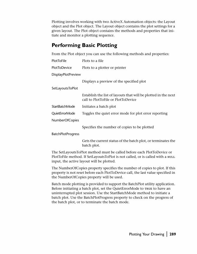
Plotting involves working with two ActiveX Automation objects: the Layout object and the Plot object. The Layout object contains the plot settings for a given layout. The Plot object contains the methods and properties that ini-tiate and monitor a plotting sequence.
Performing Basic Plotting
From the Plot object you can use the following methods and properties:
PlotToFile Plots to a file
PlotToDevice Plots to a plotter or printer
DisplayPlotPreview
Displays a preview of the specified plot
SetLayoutsToPlot
Establish the list of layouts that will be plotted in the next call to PlotToFile or PlotToDevice
StartBatchMode Initiates a batch plot
QuietErrorMode Toggles the quiet error mode for plot error reporting
NumberOfCopies
Specifies the number of copies to be plotted
BatchPlotProgress
Gets the current status of the batch plot, or terminates the batch plot.
The SetLayoutsToPlot method must be called before each PlotToDevice or PlotToFile method. If SetLayoutsToPlot is not called, or is called with a NULL input, the active layout will be plotted.
The NumberOfCopies property specifies the number of copies to plot. If this property is not reset before each PlotToDevice call, the last value specified in the NumberOfCopies property will be used.
Batch mode plotting is provided to support the BatchPlot utility application. Before initiating a batch plot, set the QuietErrorMode to TRUE to have an uninterrupted plot session. Use the StartBatchMode method to initiate a batch plot. Use the BatchPlotProgress property to check on the progress of the batch plot, or to terminate the batch mode.
Plotting Your Drawing | 289

Plotting from Model Space
Typically, when you plot a large drawing such as a floorplan, you can specify a scale to convert the real drawing units into plotted inches or millimeters. However, when you plot from model space, the defaults that are used if there are no settings specified include plot to system printer, plot the current dis-play, scaled to fit, 0 rotation, and 0,0 offset. To modify the plot settings, change the properties on the Layout object associated with model space.
Plotting the extents of an active model space layout
This example first checks to make sure the active space is model space. The example then establishes several plot settings. Finally, the plot is sent using the PlotToDevice method.
Sub Ch9_PrintModelSpace() ’ Verify that the active space is model space If ThisDrawing.ActiveSpace = acPaperSpace Then ThisDrawing.MSpace = True ThisDrawing.ActiveSpace = acModelSpace End If ’ Set the extents and scale of the plot area ThisDrawing.ModelSpace.Layout.PlotType = acExtents ThisDrawing.ModelSpace.Layout. _ StandardScale = acScaleToFit ’ Set the number of copies to one ThisDrawing.Plot.NumberOfCopies = 1 ’ Initiate the plot ThisDrawing.Plot.PlotToDeviceEnd Sub
The device name can be specified using the ConfigName property. This device can be overridden in the PlotToDevice method by specifying PC3 file.
Plotting from Paper Space
You can plot one or many paper space layouts at a time. You can plot the active layout, as demonstrated in “Plotting from Model Space” on page 290, or you can specify by name the layouts to be plotted.
Plotting two paper space layouts
This example sends the two paper space layouts “Layout1” and “Layout2” to the default plot device. Note that these two layouts must exist in the drawing for this code to run. This example first creates a string array containing the names of the layouts to be plotted. It then uses this array as input to the
290 | Chapter 9 Defining Layouts and Plotting

SetLayoutsToPlot method. The example then sets the number of copies to be plotted, and finally sends the plot to the default device.
Sub Ch9_PrintPaperSpace() ’ Establish the paper space layouts to be plotted Dim strLayouts(0 To 1) As String Dim varLayouts As Variant strLayouts(0) = "Layout1" strLayouts(1) = "Layout2" varLayouts = strLayouts ThisDrawing.Plot.SetLayoutsToPlot varLayouts ’ Set the number of copies to one ThisDrawing.Plot.NumberOfCopies = 1 ’ Initiate the plot ThisDrawing.Plot.PlotToDeviceEnd Sub
Plotting Your Drawing | 291

292

In This Chapter
Advanced Drawing and Organizational Techniques
10■ Working with Raster Images
■ Using Blocks and Attributes
■ Using External References
■ Assigning and Retrieving Extended Data
As you gain experience, you can take advantage of the
many advanced features of AutoCAD to further enhance
your applications.
You can include in your drawing raster images such as
aerial, satellite, and digital photographs, as well as com-
puter-rendered images.
In addition to enhancing your drawing’s visual image,
AutoCAD provides several features to help you organize
data, allowing you to further expand the intelligence of
the objects in your drawing.
293
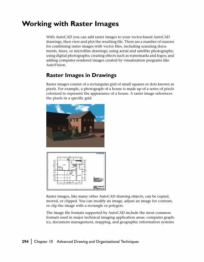
Working with Raster Images
With AutoCAD you can add raster images to your vector-based AutoCAD drawings, then view and plot the resulting file. There are a number of reasons for combining raster images with vector files, including scanning docu-ments, faxes, or microfilm drawings; using aerial and satellite photographs; using digital photographs; creating effects such as watermarks and logos; and adding computer-rendered images created by visualization programs like AutoVision.
Raster Images in Drawings
Raster images consist of a rectangular grid of small squares or dots known as pixels. For example, a photograph of a house is made up of a series of pixels colorized to represent the appearance of a house. A raster image references the pixels in a specific grid.
Raster images, like many other AutoCAD drawing objects, can be copied, moved, or clipped. You can modify an image, adjust an image for contrast, or clip the image with a rectangle or polygon.
The image file formats supported by AutoCAD include the most common formats used in major technical imaging application areas: computer graph-ics, document management, mapping, and geographic information systems
294 | Chapter 10 Advanced Drawing and Organizational Techniques
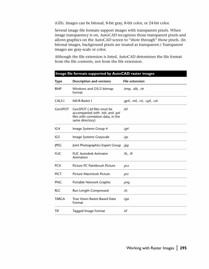
(GIS). Images can be bitonal, 8-bit gray, 8-bit color, or 24-bit color.
Several image file formats support images with transparent pixels. When image transparency is on, AutoCAD recognizes those transparent pixels and allows graphics on the AutoCAD screen to “show through” those pixels. (In bitonal images, background pixels are treated as transparent.) Transparent images are gray-scale or color.
Although the file extension is listed, AutoCAD determines the file format from the file contents, not from the file extension.
Image file formats supported by AutoCAD raster images
Type Description and versions File extension
BMP Windows and OS/2 bitmap format
.bmp, .dib, .rle
CALS-I Mil-R-Raster I .gp4, .mil, .rst, .cg4, .cal
GeoSPOT GeoSPOT (.bil files must be accompanied with .hdr, and .pal files with correlation data, in the same directory)
.bil
IG4 Image Systems Group 4 .ig4
IGS Image Systems Grayscale .igs
JPEG Joint Photographics Expert Group .jpg
FLIC FLIC Autodesk Animator Animation
.flc, .fli
PCX Picture PC Paintbrush Picture .pcx
PICT Picture Macintosh Picture .pct
PNG Portable Network Graphic .png
RLC Run Length Compressed .rlc
TARGA True Vision Raster-Based Data Format
.tga
TIF Tagged Image Format .tif
Working with Raster Images | 295

Attaching and Scaling a Raster Image
Images can be placed in drawings files, but they are not actually part of the drawing file. The image is linked to the drawing file through a path name or a data management document ID. Linked image paths can be changed or removed at any time. By attaching images using linked image paths, you can place images in your drawing, only slightly increasing the drawing file size. To attach an image, you create a Raster object in your drawing using the AddRaster method. This method takes four values as input: the name of the image file to attach, the insertion point in the drawing to place the image, the scale factor of the image, and the rotation angle of the image. Remember, the Raster object represents an independent link to the image, not the image itself.
Once you’ve attached an image, you can reattach it many times, creating a new Raster object for each attachment. Each attachment has its own clip boundary and its own settings for brightness, contrast, fade, and transparency. A single image can be cut into multiple pieces and rearranged independently in your drawing.
You can set the raster image scale factor when you create the Raster object so that the image’s geometry scale matches the scale of the geometry created in the AutoCAD drawing. When you select an image to attach, the image is inserted at a scale factor of 1 image unit of measurement to 1 AutoCAD unit of measurement. To set the image scale factor, you need to know the scale of the geometry on the image, and you need to know what unit of measure-ment (inches, feet, and so forth) you want to use to define 1 AutoCAD unit. The image file must contain resolution information defining the DPI, or dots per inch, and number of pixels in the image.
If an image has resolution information, AutoCAD combines it with the scale factor and the AutoCAD unit of measurement you supply to scale the image in your drawing. For example, if your raster image is a scanned blueprint on which the scale is 1 inch equals 50 feet, or 1:600, and your AutoCAD drawing is set up so that 1 unit represents 1 inch, then to set the scale factor of the image, you enter 600 for the ScaleFactor parameter of the AddRaster method. AutoCAD then inserts the image at a scale that brings the geometry in the image into alignment with the vector geometry in the drawing.
NOTE If no resolution information is defined with the attached image file, AutoCAD calculates the image’s original width as one unit. After insertion, the image width in AutoCAD units is equal to the scale factor.
296 | Chapter 10 Advanced Drawing and Organizational Techniques

Attaching a raster image
This example adds a raster image in model space. This example uses the watch.jpg found in the sample directory. If you do not have this image, or it is located in a different directory, insert a valid path and file name for the imageName variable.
Sub Ch10_AttachingARaster() Dim insertionPoint(0 To 2) As Double Dim scalefactor As Double Dim rotationAngle As Double Dim imageName As String Dim rasterObj As AcadRasterImage imageName = "C:/Acad2000/sample/watch.jpg" insertionPoint(0) = 5 insertionPoint(1) = 5 insertionPoint(2) = 0 scalefactor = 2 rotationAngle = 0 On Error GoTo ERRORHANDLER ’ Attach the raster image in model space Set rasterObj = ThisDrawing.ModelSpace.AddRaster _ (imageName, insertionPoint, _ scalefactor, rotationAngle) ZoomAll Exit SubERRORHANDLER: MsgBox Err.DescriptionEnd Sub
Managing Raster Images
You can manage raster image name, file name, and file paths using the prop-erties of the Raster object.
Changing Image File PathsThe path and file name of an image is queried or changed using the ImageFile property. The path set by this property is the actual path where AutoCAD looks for the image.
If AutoCAD cannot locate the drawing (for example, if you have moved the file to a different directory than the one saved with the ImageFile property), it removes relative or absolute path information from the name (for example, \images\tree.tga or c:\my project\images\tree.tga becomes tree.tga) and searches the paths you have defined using the SetProjectFilePath method on the Preferences object. If the drawing is not located in the paths, it attempts the first search path again.
Working with Raster Images | 297

You can remove the path from the file name or specify a relative path by resetting the ImageFile property.
Changing the path in the ImageFile property does not affect the project files’ search-path settings.
Naming ImagesImage names are not necessarily the same as image file names. When you attach an image to a drawing, AutoCAD uses the file name without the file extension as the image name. You can change the image name without affecting the name of the file.
The image file is represented by the ImageFile property on the Raster object. Changing the ImageFile property will change the image in the drawing. The image name is represented by the Name property, and changing the Name property will change the name of the image only, not the file associated with it.
Modifying Images and Image Boundaries
All images have an image boundary. When you attach an image to a drawing, the image boundary inherits the current property settings, including color, layer, linetype, and linetype scale. If the image is a bitonal image, the image color and boundary color are the same.
As with other AutoCAD objects, you can modify images and their boundary properties, as shown here:
■ Display or hide the image boundary■ Modify the image layer, boundary color, and linetype■ Change the image location■ Scale, rotate, and change the width and height of the image■ Toggle the image visibility■ Change the image transparency■ Change the image brightness, contrast, and fade■ Change the quality and speed of image display
Showing and Hiding Image BoundariesHiding an image boundary ensures that the image cannot accidentally be moved or modified and prevents the boundary from being plotted or displayed. When image boundaries are hidden, clipped images are still displayed to their specified boundary limits; only the boundary is affected. Showing and hiding image boundaries affects all images attached to your drawing.
298 | Chapter 10 Advanced Drawing and Organizational Techniques

To show or hide the image boundaries, use the ClippingEnabled property.
NOTE This property affects only the image boundary. To see a change in the image when toggling this property, look closely at the small boundary surround-ing the image.
Changing Image Layer, Boundary Color, and Boundary LinetypeYou can change the color and linetype of image boundaries and the layer of an image using the following properties:
Layer Specifies the layer for the image
Color Specifies the color of the image boundary
Linetype Specifies the linetype of the image
Changing Image Scale, Rotation, Location, Width, and HeightYou can change the scale, rotation, location, width, and height of an image using the following methods and properties:
ScaleEntity Scales the image
Rotate Rotates the image
Origin Specifies the image location
Width Specifies the width of the image in pixels
Height Specifies the height of the image in pixels
ImageWidth Specifies the width of the image in database units
ImageHeight Specifies the height of the image in database units
ShowRotation Determines if the raster is displayed rotated
Working with Raster Images | 299

Changing Image VisibilityImage visibility affects the redraw speed by hiding images in the current drawing session. Hidden images are not displayed or plotted; only the draw-ing boundary is displayed. To hide images, set the ImageVisibility property to FALSE. To redisplay the images, set the ImageVisibility property to TRUE.
Modifying Bitonal Image Color and TransparencyBitonal raster images are images consisting only of a foreground color and a background color. When you attach a bitonal image, the foreground pixels in the image inherit the current layer settings for color. In addition to the modifications you can make to any attached image, you can modify bitonal images by changing the foreground color and by turning the transparency of the background on and off.
NOTE Bitonal images and bitonal image boundaries are always the same color.
To change the foreground color of a bitonal image, use the Color property. To turn the transparency on and off, use the Transparency property.
Adjusting Image Brightness, Contrast, and FadeYou can adjust image brightness, contrast, and fade in AutoCAD to the dis-play of the image and to plotted output without affecting the original raster image file. Adjust brightness to darken or lighten an image. Adjust contrast to make poor-quality images easier to read. Adjust fade to make vectors easier to see over images, and to create a watermark effect in your plotted output.
Use the following properties to adjust brightness, contrast, and fade:
Brightness Specifies the brightness level of an image
Contrast Specifies the contrast level of an image
Fade Specifies the fade level of an image
300 | Chapter 10 Advanced Drawing and Organizational Techniques

Clipping Images
You can define a region of an image for display and plotting by clipping the image. The clipping boundary must be a 2D polygon or rectangle with verti-ces constrained to lay within the boundaries of the image. Multiple instances of the same image can have different boundaries.
To clip an image
1 Turn on the image boundaries using the ClippingEnabled property.
2 Specify the clipping boundary and perform the clip using the ClipBoundary method. This method takes one value as input: a variant array of 2D WCS coordinates specifying the clipping boundary of a raster image.
Changing the Clipping BoundaryTo change an existing clipping boundary, simply repeat the previous steps. The old boundary will be deleted and the new boundary will replace the old one.
Showing and Hiding the Clipping BoundaryYou can display a clipped image using the clipping boundary, or you can hide the clipping boundary and display the original image boundaries. To hide a clipping boundary and display the original image, set the ClippingEnabled property to FALSE. To display the clipped image, set the ClippingEnabled property to TRUE.
rectangular clipping boundary applied image after clipping boundary is applied
Working with Raster Images | 301

Clipping a raster image boundary
This example adds a raster image in model space. It then clips the image based on a clip boundary. This example uses downtown.jpg found in the sam-ple directory. If you do not have this image, or it is located in a different directory, insert a valid path and file name for the imageName variable.
Sub Ch10_ClippingRasterBoundary() Dim insertionPoint(0 To 2) As Double Dim scalefactor As Double Dim rotationAngle As Double Dim imageName As String Dim rasterObj As AcadRasterImage imageName = "C:\AutoCAD\sample\downtown.jpg" insertionPoint(0) = 5 insertionPoint(1) = 5 insertionPoint(2) = 0 scalefactor = 2 rotationAngle = 0 On Error GoTo ERRORHANDLER ’ Creates a raster image in model space Set rasterObj = ThisDrawing.ModelSpace.AddRaster _ (imageName, insertionPoint, _ scalefactor, rotationAngle) ZoomAll ’ Establish the clip boundary with an array of points Dim clipPoints(0 To 9) As Double clipPoints(0) = 6: clipPoints(1) = 6.75 clipPoints(2) = 7: clipPoints(3) = 6 clipPoints(4) = 6: clipPoints(5) = 5 clipPoints(6) = 5: clipPoints(7) = 6 clipPoints(8) = 6: clipPoints(9) = 6.75 ’ Clip the image rasterObj.ClipBoundary clipPoints ’ Enable the display of the clip rasterObj.ClippingEnabled = True ThisDrawing.Regen acActiveViewport Exit Sub ERRORHANDLER: MsgBox Err.DescriptionEnd Sub
302 | Chapter 10 Advanced Drawing and Organizational Techniques

Using Blocks and Attributes
AutoCAD provides several features to help you manage objects in your draw-ings. With blocks you can organize and manipulate many objects as one component. Attributes associate items of information with the blocks in your drawings—for example, part numbers and prices.
Using AutoCAD external references, or xrefs, you can attach or overlay entire drawings to your current drawing. When you open your current drawing, any changes made in the referenced drawing appear in the current drawing.
Working with Blocks
A block is a collection of objects you can associate together to form a single object, or a block reference. You can insert, scale, and rotate a block reference in a drawing. You can explode a block reference into its component objects, modify them, and redefine the block. AutoCAD updates all future instances of that block reference based on the definition of the block.
Blocks streamline the drawing process. For example, you can use blocks to do the following:
■ Build a standard library of frequently used symbols, components, or stan-dard parts. You can insert the same block reference numerous times instead of re-creating the drawing elements each time
■ Revise drawings efficiently by inserting, relocating, and copying block references as components rather than individual geometric objects
■ Save disk space by storing all references to the same block as one block definition in the drawing database
When you insert a block in your drawing, you are creating a block reference. Each time you insert a block reference, you can assign a scale factor and rotation angle to the inserted block. You can also scale a block reference using different values in any coordinate (X, Y, Z) direction.
default values X scale = 0.5 Y scale = 1
X scale = 1 Y scale = 0.5
rotationangle = 45
Using Blocks and Attributes | 303

Blocks make it possible for you to organize your drawing tasks in a systematic way so you can set up, redesign, and sort the objects in your drawings and the information associated with them.
Working with Layers, Colors, and LinetypesBlocks can be defined from objects originally drawn on different layers with different colors and linetypes. You can preserve the layer, color, and linetype information of objects in a block. Then, each time you insert the block, you have each object within the block drawn on its original layer with its original color and linetype.
When a block reference that consists of objects drawn on layer 0 (with the color and linetype BYLAYER assigned) is placed on the current layer, it assumes the color and linetype properties of the current layer. The current layer’s properties override any color or linetype explicitly assigned to that block reference.
A block reference consisting of objects that have color or linetype specified with BYBLOCK is drawn with the color and linetype that are current when the block reference is inserted. If the color and linetype are not explicitly assigned, the block reference assumes the color and linetype of the layer.
Nesting BlocksA block can contain other (nested) block references. For example, you can insert a drawing of a mechanical assembly containing a housing, a bracket, and fasteners, with each fastener composed of a bolt, washer, and nut. The only restriction on nested blocks is that you cannot insert or create blocks that reference themselves.
object layer
all layers together
dimension and hatch layer
fasteners layer
304 | Chapter 10 Advanced Drawing and Organizational Techniques

Defining BlocksTo create a new block, use the Add method. This method requires two values as input: the location in the drawing where the block is added and the name of the block to create.
Once created, you can add any geometrical object, or another block, to the newly created block. You can then insert an instance of the block into the drawing. An inserted block is an object called a block reference.
You can also create a block by using the WBlock method to group objects in a separate drawing file. The drawing file can then be used as a block defini-tion for other drawings. AutoCAD considers any drawing you insert into another drawing to be a block.
Inserting BlocksYou can insert blocks or entire drawings into the current drawing with the InsertBlock method. The InsertBlock method takes six values as input: the insertion point, the name of the block or drawing to insert, the X-scale factor, the Y-scale factor, the Z-scale factor, and the rotation angle.
When you insert an entire drawing into another drawing, AutoCAD treats the inserted drawing like any other block reference. Subsequent insertions reference the block definition (which contains the geometric description of the block) with different position, scale, and rotation settings, as shown in the following illustration. If you change the original drawing after inserting it, the changes have no effect on the inserted block. If you want the inserted block to reflect the changes you made to the original drawing, you can rede-
assembly block blocks that are components of assembly block
fastener block blocks that are components of fastener block
Using Blocks and Attributes | 305

fine the block by reinserting the original drawing. This can be done with the InsertBlock method.
If you insert a drawing as a block, the file name is automatically used as the name of the block. You can change the name of the block by using the Name property once the block has been created.
By default, AutoCAD uses the coordinate (0, 0, 0) as the base point for inserted drawings. You can change the base point of a drawing by opening the original drawing and using the SetVariable method to specify a different insertion base point for the INSBASE system variable. AutoCAD uses the new base point the next time you insert the drawing.
If the drawing you insert contains PaperSpace objects, those objects are not included in the current drawing’s block definition. To use the PaperSpace objects in another drawing, open the original drawing and use the Add method to define the PaperSpace objects as a block. You can insert the draw-ing into another drawing in either paper space or model space.
A block reference cannot be iterated to find the original objects that compose it. However, you can iterate the original block definition, or you can explode the block reference into its original components.
You can also insert an array of blocks using the AddMInsertBlock method. This method does not insert a single block into your drawing, as the InsertBlock does, but instead inserts an array of the specified block. This method returns an MInsertBlock object.
fastener block references of fasteners
306 | Chapter 10 Advanced Drawing and Organizational Techniques

Defining a block and inserting the block into a drawing
This example defines a block and adds a circle to the block definition. It then inserts the block into the drawing as a block reference.
Sub Ch10_InsertingABlock() ’ Define the block Dim blockObj As AcadBlock Dim insertionPnt(0 To 2) As Double insertionPnt(0) = 0 insertionPnt(1) = 0 insertionPnt(2) = 0 Set blockObj = ThisDrawing.Blocks.Add _ (insertionPnt, "CircleBlock") ’ Add a circle to the block Dim circleObj As AcadCircle Dim center(0 To 2) As Double Dim radius As Double center(0) = 0 center(1) = 0 center(2) = 0 radius = 1 Set circleObj = blockObj.AddCircle(center, radius) ’ Insert the block Dim blockRefObj As AcadBlockReference insertionPnt(0) = 2 insertionPnt(1) = 2 insertionPnt(2) = 0 Set blockRefObj = ThisDrawing.ModelSpace.InsertBlock _ (insertionPnt, "CircleBlock", 1#, 1#, 1#, 0) ZoomAll MsgBox "The circle belongs to " & blockRefObj.ObjectNameEnd Sub
NOTE After insertion, the external file’s WCS is aligned parallel to the XY plane of the current UCS in the current drawing. Thus, a block from an external file is inserted at any orientation in space by setting the UCS before inserting it.
Exploding a Block ReferenceUse the Explode method to break a block reference. By exploding a block ref-erence, you can modify the block or add to or delete the objects that define it.
Displaying the results of an exploded block reference
This example creates a block and adds a circle to the definition of the block. The block is then inserted into the drawing as a block reference. The block reference is then exploded, and the objects resulting from the explode pro-cess are displayed along with their object types.
Using Blocks and Attributes | 307

Sub Ch10_ExplodingABlock() ’ Define the block Dim blockObj As AcadBlock Dim insertionPnt(0 To 2) As Double insertionPnt(0) = 0 insertionPnt(1) = 0 insertionPnt(2) = 0 Set blockObj = ThisDrawing.Blocks.Add _ (insertionPnt, "CircleBlock") ’ Add a circle to the block Dim circleObj As AcadCircle Dim center(0 To 2) As Double Dim radius As Double center(0) = 0 center(1) = 0 center(2) = 0 radius = 1 Set circleObj = blockObj.AddCircle(center, radius) ’ Insert the block Dim blockRefObj As AcadBlockReference insertionPnt(0) = 2 insertionPnt(1) = 2 insertionPnt(2) = 0 Set blockRefObj = ThisDrawing.ModelSpace.InsertBlock _ (insertionPnt, "CircleBlock", 1#, 1#, 1#, 0) ZoomAll MsgBox "The circle belongs to " & blockRefObj.ObjectName ’ Explode the block reference Dim explodedObjects As Variant explodedObjects = blockRefObj.Explode ’ Loop through the exploded objects Dim I As Integer For I = 0 To UBound(explodedObjects) explodedObjects(I).Color = acRed explodedObjects(I).Update MsgBox "Exploded Object " & I & ": " _ & explodedObjects(I).ObjectName explodedObjects(I).Color = acByLayer explodedObjects(I).Update NextEnd Sub
Redefining a BlockUse any of the Block object methods and properties to redefine a block. When you redefine a block, all the references to that block in the drawing are immediately updated to reflect the new definition.
308 | Chapter 10 Advanced Drawing and Organizational Techniques

Redefinition affects previous and future insertions of a block. Constant attributes are lost and replaced by any new constant attributes. Variable attributes remain unchanged, even if the new block has no attributes.
Redefining the objects in a block definition
This example creates a block and adds a circle to the definition of the block. The block is then inserted into the drawing as a block reference. The circle in the block definition is updated, and the block reference updates automatically.
Sub Ch10_RedefiningABlock() ’ Define the block Dim blockObj As AcadBlock Dim insertionPnt(0 To 2) As Double insertionPnt(0) = 0 insertionPnt(1) = 0 insertionPnt(2) = 0 Set blockObj = ThisDrawing.Blocks.Add _ (insertionPnt, "CircleBlock") ’ Add a circle to the block Dim circleObj As AcadCircle Dim center(0 To 2) As Double Dim radius As Double center(0) = 0 center(1) = 0 center(2) = 0 radius = 1 Set circleObj = blockObj.AddCircle(center, radius) ’ Insert the block Dim blockRefObj As AcadBlockReference insertionPnt(0) = 2 insertionPnt(1) = 2 insertionPnt(2) = 0 Set blockRefObj = ThisDrawing.ModelSpace.InsertBlock _ (insertionPnt, "CircleBlock", 1#, 1#, 1#, 0) ZoomAll ’ Redefine the circle in the block, ’ and update the block reference circleObj.radius = 3 blockRefObj.UpdateEnd Sub
Using Blocks and Attributes | 309

Working with Attributes
An attribute reference provides an interactive label or tag for you to attach text to a block. Examples of data are part numbers, prices, comments, and owners’ names.
You can extract attribute reference information from a drawing and use that information in a spreadsheet or database to produce items such as a parts list or bill of materials (BOM). You can associate more than one attribute refer-ence with a block, provided that each attribute reference has a different tag. You can also define constant attributes. Because they have the same value in every occurrence of the block, AutoCAD does not prompt for a value when you insert the block.
Attributes can be invisible, which means the attribute reference is not dis-played or plotted. However, information on the attribute reference is stored in the drawing file.
Creating Attribute Definitions and Attribute ReferencesTo create an attribute reference, first you must create an attribute definition on a block by using the AddAttribute method. This method requires six val-ues as input: the height of the attribute text, the attribute mode, a prompt string, the insertion point, the tag string, and the default attribute value.
block and attribute definition
inserted blocks with attributes
310 | Chapter 10 Advanced Drawing and Organizational Techniques

The mode value is optional. There are five constants you can enter to specify the Attribute mode:
acAttributeModeNormal
Specifies that the current mode of each attribute is maintained.
acAttributeModeInvisible
Specifies that attribute values won’t appear when you insert the block. The ATTDISP command overrides the Invisible mode.
acAttributeModeConstant
Gives attributes a fixed value for block insertions.
acAttributeModeVerify
Prompts you to verify that the attribute value is correct when you insert the block.
acAttributeModePreset
Sets the attribute to its default value when you insert a block containing a present attribute. The value cannot be edited in this mode.
You can enter none, any combination, or all of the options. To specify a com-bination of options, add the constants together. For example, you can enter acAttributeModeInvisible + acAttributeModeConstant.
The prompt string appears when a block containing the attribute is inserted. The default for this string is the Tag string. Input acAttributeModeConstant for the mode to disable the prompt.
The tag string identifies each occurrence of the attribute. You can use any characters except spaces or exclamation points. AutoCAD changes lowercase letters to uppercase.
Once the attribute definition is defined in a block, whenever you insert the block using the InsertBlock method you can specify a different value for the attribute reference.
An attribute definition is associated to the block upon which it is created. Attribute definitions created on model space or paper space are not consid-ered attached to any given block.
Using Blocks and Attributes | 311

Defining an attribute definition
This example creates a block and then adds an attribute to the block. The block is then inserted into the drawing.
Sub Ch10_CreatingAnAttribute() ’ Define the block Dim blockObj As AcadBlock Dim insertionPnt(0 To 2) As Double insertionPnt(0) = 0 insertionPnt(1) = 0 insertionPnt(2) = 0 Set blockObj = ThisDrawing.Blocks.Add _ (insertionPnt, "BlockWithAttribute") ’ Add an attribute to the block Dim attributeObj As AcadAttribute Dim height As Double Dim mode As Long Dim prompt As String Dim insertionPoint(0 To 2) As Double Dim tag As String Dim value As String height = 1 mode = acAttributeModeVerify prompt = "New Prompt" insertionPoint(0) = 5 insertionPoint(1) = 5 insertionPoint(2) = 0 tag = "New Tag" value = "New Value" Set attributeObj = blockObj.AddAttribute(height, mode, _ prompt, insertionPoint, tag, value) ’ Insert the block, creating a block reference ’ and an attribute reference Dim blockRefObj As AcadBlockReference insertionPnt(0) = 2 insertionPnt(1) = 2 insertionPnt(2) = 0 Set blockRefObj = ThisDrawing.ModelSpace.InsertBlock _ (insertionPnt, "BlockWithAttribute", 1#, 1#, 1#, 0)End Sub
312 | Chapter 10 Advanced Drawing and Organizational Techniques

Editing Attribute DefinitionsYou can use the Attribute object properties and methods to edit the attribute.
Some of the properties on an attribute include the following:
Alignment Specifies the horizontal and vertical alignment of the attribute
Backward Specifies the direction of attribute text
FieldLength Specifies the field length of the attribute
Height Specifies the height of the attribute
InsertionPoint Specifies the insertion point of the attribute
Mode Specifies the mode of the attribute
PromptString Specifies the prompt string of the attribute
Rotation Specifies the rotation of the attribute
ScaleFactor Specifies the scale factor of the attribute
TagString Specifies the tag string of the attribute
Some of the methods you can use to edit the attribute include the following:
ArrayPolar Creates a polar array
ArrayRectangular
Creates a rectangular array
Copy Copies the attribute
Erase Erases the attribute
Mirror Mirrors the attribute
Move Moves the attribute
Rotate Rotates the attribute
ScaleEntity Scales the attribute
Using Blocks and Attributes | 313

Redefining an attribute definition
This example creates a block and then adds an attribute to the block. The block is then inserted into the drawing. The attribute text is then updated to display backward.
Sub Ch10_RedefiningAnAttribute() ’ Define the block Dim blockObj As AcadBlock Dim insertionPnt(0 To 2) As Double insertionPnt(0) = 0 insertionPnt(1) = 0 insertionPnt(2) = 0 Set blockObj = ThisDrawing.Blocks.Add _ (insertionPnt, "BlockWithAttribute") ’ Add an attribute to the block Dim attributeObj As AcadAttribute Dim height As Double Dim mode As Long Dim prompt As String Dim insertionPoint(0 To 2) As Double Dim tag As String Dim value As String height = 1 mode = acAttributeModeVerify prompt = "New Prompt" insertionPoint(0) = 5 insertionPoint(1) = 5 insertionPoint(2) = 0 tag = "New Tag" value = "New Value" Set attributeObj = blockObj.AddAttribute(height, mode, _ prompt, insertionPoint, tag, value) ’ Insert the block, creating a block reference ’ and an attribute reference Dim blockRefObj As AcadBlockReference insertionPnt(0) = 2 insertionPnt(1) = 2 insertionPnt(2) = 0 Set blockRefObj = ThisDrawing.ModelSpace.InsertBlock _ (insertionPnt, "BlockWithAttribute", 1#, 1#, 1#, 0) ’ Redefine the attribute text to display backwards. attributeObj.Backward = True attributeObj.UpdateEnd Sub
314 | Chapter 10 Advanced Drawing and Organizational Techniques

Extracting Attribute InformationYou can extract attribute information from a drawing using the GetAttributes and GetConstantAttributes methods. The GetAttributes method returns an array of the attribute references attached to a block, along with their current values. The GetConstantAttributes method returns an array of constant attributes attached to the block or external reference. The attributes returned by this method are the constant attribute definitions, not attribute references.
You do not need template files to extract attribute information, and no attribute information files are created. Simply iterate the array of attribute references, using the TagString and TextString properties of the attribute ref-erence to examine the attribute information.
The TagString property represents the individual tag for the attribute refer-ence. The TextString property contains the value for the attribute reference.
Getting attribute reference information
This example creates a block and then adds an attribute to the block. The block is then inserted into the drawing. The attribute data is then returned and displayed using a message box. The attribute data is then updated for the block reference, and once again the attribute data is returned and displayed.
Sub Ch10_GettingAttributes() ’ Create the block Dim blockObj As AcadBlock Dim insertionPnt(0 To 2) As Double insertionPnt(0) = 0 insertionPnt(1) = 0 insertionPnt(2) = 0 Set blockObj = ThisDrawing.Blocks.Add _ (insertionPnt, "TESTBLOCK") ’ Define the attribute definition Dim attributeObj As AcadAttribute Dim height As Double Dim mode As Long Dim prompt As String Dim insertionPoint(0 To 2) As Double Dim tag As String Dim value As String height = 1# mode = acAttributeModeVerify prompt = "Attribute Prompt" insertionPoint(0) = 5 insertionPoint(1) = 5 insertionPoint(2) = 0 tag = "Attribute Tag" value = "Attribute Value"
Using Blocks and Attributes | 315

’ Create the attribute definition object on the block Set attributeObj = blockObj.AddAttribute _ (height, mode, prompt, _ insertionPoint, tag, value) ’ Insert the block Dim blockRefObj As AcadBlockReference insertionPnt(0) = 2 insertionPnt(1) = 2 insertionPnt(2) = 0 Set blockRefObj = ThisDrawing.ModelSpace.InsertBlock _ (insertionPnt, "TESTBLOCK", 1, 1, 1, 0) ZoomAll ’ Get the attributes for the block reference Dim varAttributes As Variant varAttributes = blockRefObj.GetAttributes ’ Move the attribute tags and values into a ’ string to be displayed in a Msgbox Dim strAttributes As String strAttributes = "" Dim I As Integer For I = LBound(varAttributes) To UBound(varAttributes) strAttributes = strAttributes + " Tag: " + _ varAttributes(I).TagString + vbCrLf + _ " Value: " + varAttributes(I).textString Next MsgBox "The attributes for blockReference " + _ blockRefObj.Name & " are: " & vbCrLf _ & strAttributes ’ Change the value of the attribute ’ Note: There is no SetAttributes. Once you have the ’ variant array, you have the objects. ’ Changing them changes the objects in the drawing. varAttributes(0).textString = "NEW VALUE!" ’ Get the attributes again Dim newvarAttributes As Variant newvarAttributes = blockRefObj.GetAttributes ’ Again, display the tags and values strAttributes = "" For I = LBound(varAttributes) To UBound(varAttributes) strAttributes = strAttributes + " Tag: " + _ newvarAttributes(I).TagString + vbCrLf + _ " Value: " + newvarAttributes(I).textString Next MsgBox "The attributes for blockReference " & _ blockRefObj.Name & " are: " & vbCrLf _ & strAttributesEnd Sub
316 | Chapter 10 Advanced Drawing and Organizational Techniques

Using External References
An external reference (xref) links another drawing to the current drawing. When you insert a drawing as a block, the block and all of the associated geometry is stored in the current drawing database. It is not updated if the original drawing changes. When you insert a drawing as an xref, however, the xref is updated when the original drawing changes. A drawing that contains xrefs, therefore, always reflects the most current editing of each externally referenced file.
Like a block reference, an xref is displayed in the current drawing as a single object. However, an xref does not significantly increase the file size of the current drawing and cannot be exploded. As with blocks, you can nest xrefs that are attached to your drawing.
Updating Xrefs
When you open or plot your drawing, AutoCAD reloads each xref to reflect the latest state of the referenced drawing. After you make changes to an externally referenced drawing and save the file, other users can access your changes immediately by reloading the xref.
Attaching Xrefs
Attaching an xref links one drawing (the reference file, or xref) to the current drawing. When a drawing references an xref, AutoCAD attaches only the xref definition to the drawing, unlike regular blocks, where the block definition and the contents of the block are stored with the current drawing. AutoCAD reads the reference drawing to determine what to display in the current draw-ing. If the reference file is missing or corrupt, its data is not displayed in the current drawing. Each time you open a drawing, AutoCAD loads all graphical and non-graphical (such as layers, linetypes, and text styles) objects from ref-erenced files. If VISRETAIN is on, AutoCAD stores any updated xref-dependent layer information in the current drawing.
You can attach as many copies of an xref as you want, and each can have a different position, scale, and rotation. You can also control the dependent layers and linetype properties that are defined in the xref.
To attach an xref, use the AttachExternalReference method. This method requires you to input the path and file name of the drawing to be referenced, the name the xref is to use in the current drawing, the insertion point, the scale, and rotation information for the xref. The AttachExternalReference method returns the newly created ExternalReference object.
Using External References | 317
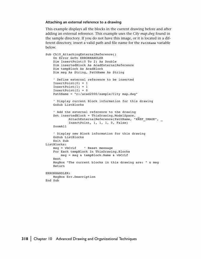
Attaching an external reference to a drawing
This example displays all the blocks in the current drawing before and after adding an external reference. This example uses the City map.dwg found in the sample directory. If you do not have this image, or it is located in a dif-ferent directory, insert a valid path and file name for the PathName variable below.
Sub Ch10_AttachingExternalReference() On Error GoTo ERRORHANDLER Dim InsertPoint(0 To 2) As Double Dim insertedBlock As AcadExternalReference Dim tempBlock As AcadBlock Dim msg As String, PathName As String ’ Define external reference to be inserted InsertPoint(0) = 1 InsertPoint(1) = 1 InsertPoint(2) = 0 PathName = "c:/acad2000/sample/City map.dwg" ’ Display current Block information for this drawing GoSub ListBlocks ’ Add the external reference to the drawing Set insertedBlock = ThisDrawing.ModelSpace. _ AttachExternalReference(PathName, "XREF_IMAGE", _ InsertPoint, 1, 1, 1, 0, False) ZoomAll ’ Display new Block information for this drawing GoSub ListBlocks Exit SubListBlocks: msg = vbCrLf ’ Reset message For Each tempBlock In ThisDrawing.Blocks msg = msg & tempBlock.Name & vbCrLf Next MsgBox "The current blocks in this drawing are: " & msg Return ERRORHANDLER: MsgBox Err.DescriptionEnd Sub
318 | Chapter 10 Advanced Drawing and Organizational Techniques

Overlaying XrefsOverlaying is similar to attaching, except when a drawing is attached or over-laid. Any other overlays nested in it are ignored and, therefore, not displayed. In other words, nested overlays are not read in.
It is recommended you use overlaying when you reference geometry that is not useful for other users to see when they reference your drawing. For exam-ple, you may have created a wiring plan for a house and need to reference the floorplan of the house. If you have chosen to overlay (rather than attach) the floorplan, then another user, who doesn’t need to see the floorplan, can xref your wiring plan without the floorplan attached.
Overlaid xrefs are designed for data sharing. By overlaying an xref, you can see how your drawing relates to other drawings. Also, overlaying an xref reduces the possibility that you might create self-referencing drawings (circu-lar xrefs).
To overlay an xref, set the bOverlay parameter of the AttachExternalReference method to TRUE.
Detaching Xrefs
You can detach an xref definition to remove the xrefs completely from your drawing. You can also erase the individual xref instances. Detaching the xref definition removes all dependent symbols associated with that xref. If all the instances of an xref are erased from the drawing, AutoCAD removes the xref definition the next time the drawing is opened.
To detach an xref, use the Detach method. You cannot detach a nested xref.
Using External References | 319
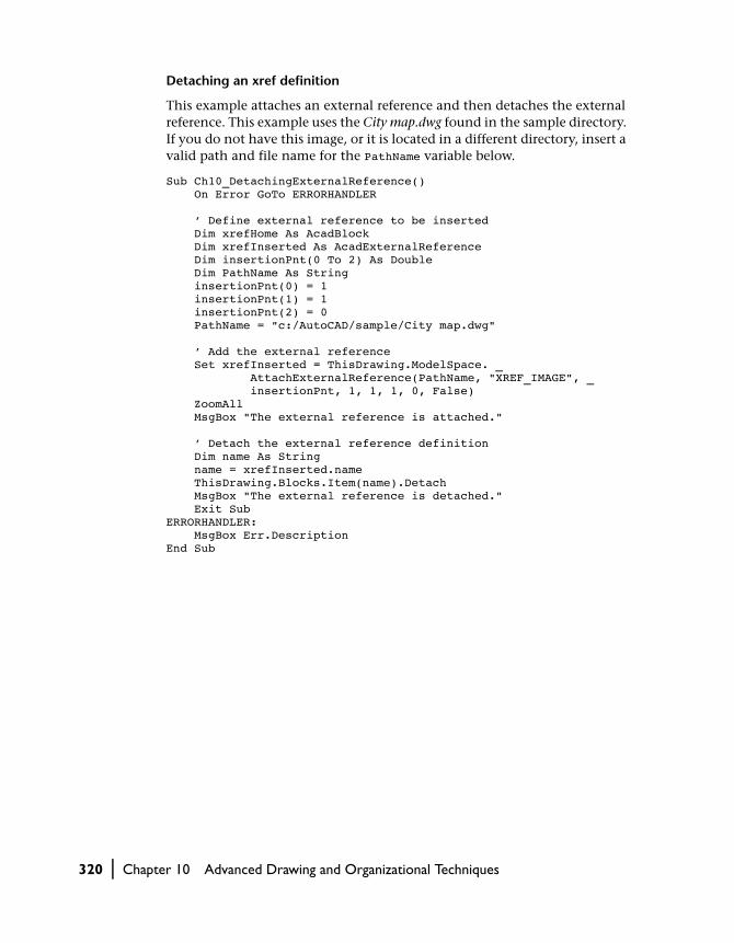
Detaching an xref definition
This example attaches an external reference and then detaches the external reference. This example uses the City map.dwg found in the sample directory. If you do not have this image, or it is located in a different directory, insert a valid path and file name for the PathName variable below.
Sub Ch10_DetachingExternalReference() On Error GoTo ERRORHANDLER ’ Define external reference to be inserted Dim xrefHome As AcadBlock Dim xrefInserted As AcadExternalReference Dim insertionPnt(0 To 2) As Double Dim PathName As String insertionPnt(0) = 1 insertionPnt(1) = 1 insertionPnt(2) = 0 PathName = "c:/AutoCAD/sample/City map.dwg" ’ Add the external reference Set xrefInserted = ThisDrawing.ModelSpace. _ AttachExternalReference(PathName, "XREF_IMAGE", _ insertionPnt, 1, 1, 1, 0, False) ZoomAll MsgBox "The external reference is attached." ’ Detach the external reference definition Dim name As String name = xrefInserted.name ThisDrawing.Blocks.Item(name).Detach MsgBox "The external reference is detached." Exit SubERRORHANDLER: MsgBox Err.DescriptionEnd Sub
320 | Chapter 10 Advanced Drawing and Organizational Techniques

Reloading Xrefs
If someone modifies an externally referenced drawing while you are working on the host drawing to which that xref is attached, you can update that xref drawing using the Reload method. When you reload, the selected xref draw-ing is updated in your host drawing. Also, if you have unloaded an xref, you can choose to reload that externally referenced drawing at any time.
Reloading an xref definition
This example attaches an external reference and then reloads the external reference. This example uses the City map.dwg found in the sample directory. If you do not have this image, or it is located in a different directory, insert a valid path and file name for the PathName variable below.
Sub Ch10_ReloadingExternalReference() On Error GoTo ERRORHANDLER ’ Define external reference to be inserted Dim xrefHome As AcadBlock Dim xrefInserted As AcadExternalReference Dim insertionPnt(0 To 2) As Double Dim PathName As String insertionPnt(0) = 1 insertionPnt(1) = 1 insertionPnt(2) = 0 PathName = "c:/AutoCAD/sample/City map.dwg" ’ Add the external reference to the block Set xrefInserted = ThisDrawing.ModelSpace. _ AttachExternalReference(PathName, "XREF_IMAGE", _ insertionPnt, 1, 1, 1, 0, False) ZoomAll MsgBox "The external reference is attached." ’ Reload the external reference definition ThisDrawing.Blocks.Item(xrefInserted.name).Reload MsgBox "The external reference is reloaded." Exit SubERRORHANDLER: MsgBox Err.DescriptionEnd Sub
Using External References | 321

Unloading Xrefs
To unload an xref use the Unload method. When you unload a referenced file that is not being used in the current drawing, the AutoCAD performance is enhanced by not having to read and display unnecessary drawing geome-try or symbol table information. The xref geometry and that of any nested xref is not displayed in the current drawing until the xref is reloaded.
Unloading an xref definition
This example attaches an external reference and then unloads the external reference. This example uses the City map.dwg found in the sample directory. If you do not have this image, or it is located in a different directory, insert a valid path and file name for the PathName variable below.
Sub Ch10_UnloadingExternalReference() On Error GoTo ERRORHANDLER ’ Define external reference to be inserted Dim xrefHome As AcadBlock Dim xrefInserted As AcadExternalReference Dim insertionPnt(0 To 2) As Double Dim PathName As String insertionPnt(0) = 1 insertionPnt(1) = 1 insertionPnt(2) = 0 PathName = "c:/AutoCAD/sample/City map.dwg" ’ Add the external reference Set xrefInserted = ThisDrawing.ModelSpace. _ AttachExternalReference(PathName, "XREF_IMAGE", _ insertionPnt, 1, 1, 1, 0, False) ZoomAll MsgBox "The external reference is attached." ’ Unload the external reference definition ThisDrawing.Blocks.Item(xrefInserted.name).Unload MsgBox "The external reference is unloaded." Exit SubERRORHANDLER: MsgBox Err.DescriptionEnd Sub
Binding Xrefs
Binding an xref to a drawing using the Bind method makes the xref a perma-nent part of the drawing and no longer an externally referenced file. The externally referenced information becomes a block. When the externally ref-erenced drawing is updated, the bound xref is not updated. This process binds the entire drawing’s database, including all of its dependent symbols.
322 | Chapter 10 Advanced Drawing and Organizational Techniques

Dependent symbols are named objects such as blocks, dimension styles, lay-ers, linetypes, and text styles. Binding the xref allows named objects from the xref to be used in the current drawing.
The Bind method requires only one parameter: bPrefixName. If bPrefixName is set to TRUE, the symbol names of the xref drawing are prefixed in the cur-rent drawing with <blockname>$x$, where x is an integer that is automati-cally incremented to avoid overriding existing block definitions. If the bPrefixName parameter is set to FALSE, the symbol names of the xref drawing are merged into the current drawing without the prefix. If duplicate names exist, AutoCAD uses the symbols already defined in the local drawing. If you are unsure whether your drawing contains duplicate symbol names, it is rec-ommended that you set bPrefixName to TRUE.
Binding an xref definition
This example attaches an external reference and then binds the external ref-erence to the drawing. This example uses the City map.dwg found in the sam-ple directory. If you do not have this image, or it is located in a different directory, insert a valid path and file name for the PathName variable below.
Sub Ch10_BindingExternalReference() On Error GoTo ERRORHANDLER ’ Define external reference to be inserted Dim xrefHome As AcadBlock Dim xrefInserted As AcadExternalReference Dim insertionPnt(0 To 2) As Double Dim PathName As String insertionPnt(0) = 1 insertionPnt(1) = 1 insertionPnt(2) = 0 PathName = "c:/AutoCAD/sample/City map.dwg" ’ Add the external reference Set xrefInserted = ThisDrawing.ModelSpace. _ AttachExternalReference(PathName, "XREF_IMAGE", _ insertionPnt, 1, 1, 1, 0, False) ZoomAll MsgBox "The external reference is attached." ’ Bind the external reference definition ThisDrawing.Blocks.Item(xrefInserted.name).Bind False MsgBox "The external reference is bound." Exit SubERRORHANDLER: MsgBox Err.DescriptionEnd Sub
Using External References | 323

Clipping Blocks and Xrefs
There is no method provided in ActiveX Automation for clipping the bound-aries of blocks and xrefs. Use the XCLIP command in AutoCAD, or send the XCLIP command to AutoCAD using the SendCommand method.
Demand Loading and Maximizing Xref Performance
Through a combination of demand loading and saving drawings with indexes, you can increase the performance of drawings with external refer-ences. Demand loading works in conjunction with the XLOADCTL and INDEXCTL system variables. When you turn on demand loading, if indexes have been saved in the referenced drawings, AutoCAD loads into memory only the data from the reference drawing that is necessary to regenerate the current drawing. In other words, referenced material is read in “on demand.”
To realize the maximum benefits of demand loading, you need to save the referenced drawings with layer and spatial indexes. The performance benefits of demand loading are most noticeable when you
■ Clip the xref to display a small fraction of it, and a spatial index is saved in the externally referenced drawing
■ Freeze several layers of the xref, and the externally referenced drawing is saved with a layer index
To turn on demand loading, use the XRefDemandLoad property. If you turn on demand loading with the acDemandLoadEnabledWithCopy option, AutoCAD makes a temporary copy of the externally referenced file and demand loads the temporary file. You can then demand load the xref while allowing the original reference drawing to be available for modification. When you disable demand loading, AutoCAD reads in the entire reference drawing regardless of layer visibility or clip instances.
To turn on layer and spatial indexes, set the INDEXCTL system variable using the SetVariable method. The following settings apply to the INDEXCTL sys-tem variable:
■ 0 = no indexes created■ 1 = layer index created■ 2 = spatial index created■ 3 = both spatial and layer indexes created
By default, INDEXCTL is set to 0 when you create a new AutoCAD drawing.
324 | Chapter 10 Advanced Drawing and Organizational Techniques
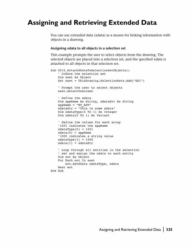
Assigning and Retrieving Extended Data
You can use extended data (xdata) as a means for linking information with objects in a drawing.
Assigning xdata to all objects in a selection set
This example prompts the user to select objects from the drawing. The selected objects are placed into a selection set, and the specified xdata is attached to all objects in that selection set.
Sub Ch10_AttachXDataToSelectionSetObjects() ’ Create the selection set Dim sset As Object Set sset = ThisDrawing.SelectionSets.Add("SS1") ’ Prompt the user to select objects sset.SelectOnScreen ’ Define the xdata Dim appName As String, xdataStr As String appName = "MY_APP" xdataStr = "This is some xdata" Dim xdataType(0 To 1) As Integer Dim xdata(0 To 1) As Variant ’ Define the values for each array ’1001 indicates the appName xdataType(0) = 1001 xdata(0) = appName ’1000 indicates a string value xdataType(1) = 1000 xdata(1) = xdataStr ’ Loop through all entities in the selection ’ set and assign the xdata to each entity Dim ent As Object For Each ent In sset ent.SetXData xdataType, xdata Next entEnd Sub
Assigning and Retrieving Extended Data | 325

Viewing the xdata of all objects in a selection set
This example displays the xdata attached with the previous example. If you attach xdata other than strings (type 1000), you will need to revise this code.
Sub Ch10_ViewXData() ’ Find the selection created in previous example Dim sset As Object Set sset = ThisDrawing.SelectionSets.Item("SS1") ’ Define the xdata variables to hold xdata information Dim xdataType As Variant Dim xdata As Variant Dim xd As Variant ’Define index counter Dim xdi As Integer xdi = 0 ’ Loop throught the objects in the selection set ’ and retrieve the xdata for the object Dim msgstr As String Dim appName As String Dim ent As AcadEntity appName = "MY_APP" For Each ent In sset msgstr = "" xdi = 0 ’ Retrieve the appName xdata type and value ent.GetXData appName, xdataType, xdata ’ If the xdataType variable is not initialized, there ’ was no appName xdata to retrieve for that entity If VarType(xdataType) <> vbEmpty Then For Each xd In xdata msgstr = msgstr & vbCrLf & xdataType(xdi) _ & ": " & xd xdi = xdi + 1 Next xd End If ’ If the msgstr variable is NULL, there was no xdata If msgstr = "" Then msgstr = vbCrLf & "NONE" MsgBox appName & " xdata on " & ent.ObjectName & _ ":" & vbCrLf & msgstr Next entEnd Sub
326 | Chapter 10 Advanced Drawing and Organizational Techniques

In This Chapter
Developing Applications with VBA
11■ More VBA Terminology
■ Working with Forms in VBA
■ Handling Errors
■ Encrypting VBA Code Modules
■ Running a VBA Macro from a Toolbar or Menu
■ Automatically Loading a VBA Project
■ Automatically Running a VBA Macro
■ Automatically Opening the VBA IDE Whenever a Project Is Loaded
■ Working in a Zero Document State
■ Distributing Your Application
Many programming tasks involve more than simply
working with the AutoCAD ActiveX object model. This
chapter provides a brief overview of creating dialog
boxes, handling errors, controlling window focus, and
distributing your application to others.
Remember, the Microsoft documentation for VBA con-
tains more information on these topics.
327

More VBA Terminology
This chapter expands your exposure to VBA. The following terms will help you understand and work within the VBA environment.
Project A set of forms and modules grouped together in a single file.
Module A group of (usually related) subroutines and functions.
Macro A public subroutine or function. Macros are exposed to the user as an executable component of your project.
Dialog box A means by which information is displayed or gathered during application execution.
Form Container for dialog box controls.
Working with Forms in VBA
Forms are the basic building blocks through which you create your own custom dialog boxes for your application. Through custom forms you can provide information to users, get information from users, or have your users control activity in the application.
Forms are like an artist’s canvas—they start out blank. To fill your canvas, you need a palette. In this case, your palette is the control toolbox. You, as the artist, place selected controls from the toolbox onto the form. You can add as many controls as you like. At any time you can adjust size and properties of both the controls and even the form itself. Finally, you add the functionality (code) to the controls that brings your form to life.
328 | Chapter 11 Developing Applications with VBA

Although Visual Basic supports different types of forms, VBA supports only the UserForm. This means some forms have been created and exported in Visual Basic that cannot be imported into VBA.
UserForms—or forms, as they are called in this guide—are always modal. This means that a form, when displayed in your running application, must be closed before the user can perform any other action in the application. We’ll look more closely at the use of modal aspect of forms in “Designing Your Application for Use with Modal Forms.”
Designing in Design Mode, Running in Run Mode
While you are building your form you are working in design mode, where you can
■ Add controls to the form■ Change the properties of the form■ Change the properties of controls on the form■ Add code to the form module
While in design mode there is no interaction among the user, the user inter-face of AutoCAD, and your form.
Once you run your application, or your user runs your application, the form is then in run mode. While in run mode you cannot make adjustments to the form directly. However, the form is now displayed in the AutoCAD user inter-face and the user can interact with the form as part of the normal operation of your application.
Creating a New Form in Your Project
To create a new form in your project
1 Open the Project window of the VBA IDE and select the project you want to add the form to.
2 From the Insert menu, choose UserForm.
A blank form is created and added to your project.
Working with Forms in VBA | 329

Adding Controls to a Form
Adding controls to a form is easy. Simply select a control from the control toolbox and drag it over to the form. When you release your mouse, a copy of the control will be placed on the form. Once the control is on the form, you can change the position and size of the control. You can copy over as many controls as you like.
In addition to the drag method previously mentioned, there are other ways of placing controls on a form.
To size a control as you place it
1 Select the desired control in the control toolbox.
2 On the form, press, drag, and release the mouse button. The selected control will be placed on the form. The size of the control depends on how far you drag the mouse.
To place several instances of the same control
1 In the control toolbox, double-click on the control you want to place.
2 On the form, click at the location you want a copy of the control placed. Move to another location on the form and click again. Another copy of the control will appear. You can add as many copies of the control as you need.
3 When you are finished with the control, return to the control toolbox and click the control one more time to deselect it.
Changing the Size and Placement of a ControlTo move a control, simply select it and drag it to its new position on the form.
To resize a control, first select the control by clicking on it once. When you select a control its border becomes visible. To resize the control, simply select one of the sizing grips now visible on the border and drag the grip to a new position. When you release the grip, the control will resize to that location. (You can resize the form in the same manner.)
To move or resize several controls at once, select each control while holding down the SHIFT key. This will highlight all the controls. You can now move or resize the controls as a group.
Using Formatting ControlsVBA provides several formatting controls to help you lay out your form. These controls can be found on the Format menu of the VBA IDE. These con-trols allow you to align controls to each other, make two or more controls the
330 | Chapter 11 Developing Applications with VBA

same size, change the spacing between controls, and center controls on the form.
Remember when using the formatting controls that several controls can be selected at once by using SHIFT.
Changing the Properties of a ControlProperties control various characteristics of a control such as its size, shape, color, label, and default values. You can set the properties of a control in design mode by using the Properties window.
To change the property of a control
1 On the form, select the desired control.
2 Open the Properties window using F4 if it is not already open.
3 In the Properties window, find the property you want to change and select the current value for that property.
4 Change the value to the new desired value for the property.
You can also change the property of a control at runtime by writing code to access that property. See the Microsoft documentation for more information on changing the property of a control at runtime.
Adding Code to a ControlNow that you have your form looking the way you want, it’s time to add some code behind your controls. To open the Code window for a control sim-ply double-click on the control in the Form window. The Code window will open, with a subroutine created for that control and its default event.
You can add code to the default event, or choose a different event from the event drop-down list at the top-right corner of the Code window.
Displaying and Hiding Forms
Now you have a beautifully designed form with fully functional code behind all the controls. The last step is getting the form displayed to the user at run-time. Displaying the form is accomplished through the VBA Show method.
The Show method can be called from any code module in your application.
Working with Forms in VBA | 331

Displaying a form
This example will display the form named “UserForm1”:
Public Sub MyApplication() UserForm1.ShowEnd Sub
The subroutine (and consequently the display of your form) is now callable as a macro from the VBARUN command or from an AutoCAD menu.
Remember that forms in VBA are modal. This means the user will not be able to interact with AutoCAD directly (such as selecting a point or object in the drawing) while the form is displayed. To allow the user access to the AutoCAD drawing, use the VBA Hide method. The Hide method hides the form and allows the user limited access to AutoCAD. When using the Hide method it is important to remember the form is not unloaded from memory. It will retain all current values while hidden.
The Hide method is called in the same manner as the Show method.
Hiding a form
UserForm1.Hide
Loading and Unloading Forms
There may be times when you want to load a form into memory during run-time, but not show the form. You may choose to do this to better control when the load time occurs in your application, or when you need program-matic access to the form but do not want to display the form to the user.
To load a form, but not display it, use the VBA Load method. The Show method can then be used to make the form visible at the appropriate time in your application’s execution. Remember, the user can’t interact with your form until it is visible.
If the Show method is called and the form has not been loaded, it will be loaded automatically.
There may also be times when you will want to unload a form specifically. Unloading a form removes that form from memory and all the memory asso-ciated with the form is reclaimed. Until the form is loaded again by using either the Load or Show method, a user can’t interact with the form, and the form can’t be manipulated programmatically. You may choose to unload a form when you know the form will not be used again in the application and you want to reclaim the memory.
332 | Chapter 11 Developing Applications with VBA

The Hide method does not perform an unload. If your application ends and a form has not been unloaded, it will be unloaded automatically. The follow-ing table compares the VBA Show, Hide, Load, and Unload methods:
Designing Your Application for Use with Modal Forms
All dialog boxes in AutoCAD VBA are modal. This means the user must respond to the dialog box before any other part of the application is allowed to continue. No subsequent code is executed until the modal dialog box is closed through either the Hide or Unload method. This requires that you, as the developer of the application, think carefully about how and when you implement dialog boxes.
For example, you may have a dialog box that requires the user to select an object in the AutoCAD drawing. For the user to be able to pick the object from the AutoCAD Application window you must hide the form by calling the Hide method. Once the object has been selected you use the Show method to redisplay the form, with all of its data still current, and continue with the application.
NOTE Although other forms in the application are disabled when a modal dia-log box is displayed, other applications are not.
VBA Show, Hide, Load, and Unload methods
Method Use
Show Displays a form. If the form has not been loaded, it is loaded automatically.
Hide Hides a form. The form is not unloaded from memory.
Load Loads a form into memory but does not display it.
Unload Unloads a form from memory. This can be done explicitly from the Unload method, or automatically at the termination of the application.
Working with Forms in VBA | 333

Handling Errors
There are three different types of errors you can encounter in your applica-tions: compile-time errors, runtime errors, and logic errors.
Compile-time errors occur during the construction of your application. These errors consist mostly of syntax mistakes, variable scoping problems, or data typing problems. In VBA, these types of errors are caught by the devel-opment environment. When you enter an incorrect line of code, the line is highlighted and an error message appears telling you the problem. Compile-time errors must be corrected before the application can run.
Runtime errors are a little more difficult to find and correct. They occur dur-ing the execution of your code, and often involve receiving information from the user. For example, if your application requires the user to enter the name of a drawing and the user enters a name for a drawing that didn’t exist, a runtime error occurs. To handle runtime errors effectively, you must predict what kinds of problems could happen, trap them, and then write code to handle these situations.
Logic errors are the most difficult to find and correct. Symptoms of logic errors include situations in which there are no compile-time errors and no runtime errors, but the outcome of your program is still incorrect. This is what programmers refer to as a bug—and a bug can be very easy or very dif-ficult to track down.
Information on finding and correcting all three types of errors can be found in documentation for your development environment. AutoCAD-specific errors fall into the runtime error category, so these types of errors will be cov-ered more fully in this documentation.
NOTE Most of the code examples provided in the AutoCAD documentation do not use error trapping. This keeps the examples simple and to the point. However, as with all programming languages, proper error trapping and han-dling is essential for a robust application.
Do You Have to Trap Runtime Errors?Most development environments provide default error handling. For VB and VBA, the default reaction to an error is to display an error message and ter-minate the application. While this behavior is adequate during the develop-ment phase of your application, it is not productive for your end-user. There may be errors that you want to ignore, or that you want to provide special responses to. There may be errors that you will want to suppress the error message display for, or simply control the message that gets displayed to the
334 | Chapter 11 Developing Applications with VBA

user. In addition, automatically terminating the application is hardly ever acceptable to the end-user.
In general, error handling is necessary whenever user-input is required and whenever working with file I/O. Remember, even if you are sure a needed file is there and available for processing, there may be conditions you haven’t thought of that could cause errors.
Trapping Runtime Errors
In VB and VBA, runtime errors are trapped using the On Error statement. This statement literally sets a trap for the system. When an error occurs, this statement automatically detours processing to your specially written error handler. The default error handling for the system is bypassed.
The On Error statement has three forms:
On Error Resume Next
On Error GoTo Label
On Error GoTo 0
The On Error Resume Next statement is used when you want to ignore errors. This statement traps the error and instead of displaying an error mes-sage and terminating the program, it simply moves on to the next line of code and continues processing. For example, if you wanted to create a sub-routine to iterate through model space and change the color of each entity, you know that AutoCAD will throw an error if you try to color an entity on a locked layer. Instead of terminating the program, simply skip the entity on the locked layer and continue processing the remaining entities. The On Error Resume Next statement lets you do just that.
Handling errors with the On Error Resume Next statement
The following subroutine iterates model space and changes the color of each entity to red. Try running this subroutine on a drawing with several entities, some of which are on a locked layer. Next, comment out the On Error Resume Next statement and run the subroutine again. You will notice the subroutine terminates at the first entity on the locked layer.
Sub Ch11_ColorEntities() Dim entry As Object On Error Resume Next For Each entry In ThisDrawing.ModelSpace entry.Color = acRed Next entryEnd Sub
Handling Errors | 335
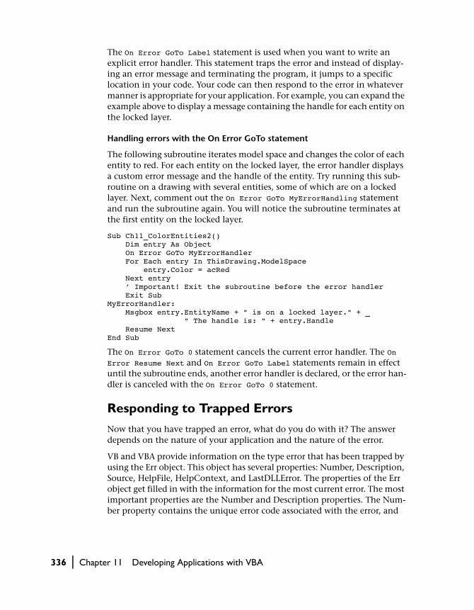
The On Error GoTo Label statement is used when you want to write an explicit error handler. This statement traps the error and instead of display-ing an error message and terminating the program, it jumps to a specific location in your code. Your code can then respond to the error in whatever manner is appropriate for your application. For example, you can expand the example above to display a message containing the handle for each entity on the locked layer.
Handling errors with the On Error GoTo statement
The following subroutine iterates model space and changes the color of each entity to red. For each entity on the locked layer, the error handler displays a custom error message and the handle of the entity. Try running this sub-routine on a drawing with several entities, some of which are on a locked layer. Next, comment out the On Error GoTo MyErrorHandling statement and run the subroutine again. You will notice the subroutine terminates at the first entity on the locked layer.
Sub Ch11_ColorEntities2() Dim entry As Object On Error GoTo MyErrorHandler For Each entry In ThisDrawing.ModelSpace entry.Color = acRed Next entry ’ Important! Exit the subroutine before the error handler Exit SubMyErrorHandler: Msgbox entry.EntityName + " is on a locked layer." + _ " The handle is: " + entry.Handle Resume NextEnd Sub
The On Error GoTo 0 statement cancels the current error handler. The On Error Resume Next and On Error GoTo Label statements remain in effect until the subroutine ends, another error handler is declared, or the error han-dler is canceled with the On Error GoTo 0 statement.
Responding to Trapped Errors
Now that you have trapped an error, what do you do with it? The answer depends on the nature of your application and the nature of the error.
VB and VBA provide information on the type error that has been trapped by using the Err object. This object has several properties: Number, Description, Source, HelpFile, HelpContext, and LastDLLError. The properties of the Err object get filled in with the information for the most current error. The most important properties are the Number and Description properties. The Num-ber property contains the unique error code associated with the error, and
336 | Chapter 11 Developing Applications with VBA

the Description property contains the error message that would normally be displayed.
In your error handler you can compare the Number property of the error to an expected value. This will help you determine the nature of the error that has occurred. Once you know what kind of error you are dealing with, you can take the appropriate action.
Responding to AutoCAD User Input Errors
The user-input methods provide a certain amount of inherent error trapping in that they require the user to enter a certain type of data. If the user tries to enter some other data, AutoCAD rejects the input and reprompts the user. Using the InitializeUserInput method with the user input functions provides additional control of the user input but can also introduce additional condi-tions that must be verified through error trapping. For an example of error trapping that is required with certain types of user-input, see “Prompting for User Input” on page 94.
Encrypting VBA Code Modules
Although VBA does not support creation of executables, it does offer pass-word protection for the visibility of the project forms, classes, and modules on a project basis. You can find this Project Protection facility in the VBA IDE menu. Choose Tools ➤ Project Properties ➤ Protection.
Running a VBA Macro from a Toolbar or Menu
You can run a VBA macro from an AutoCAD toolbar or menu by simply changing the Macro property for that toolbar or menu. The Macro property must be set equal to
-VBARUN Filename.dvb!projectname.macroname
where the file name, project name, and macro name are specified along with the command-line version of the VBARUN command. The file name is only required when the file is not loaded in the current session of AutoCAD. If the file name is provided, the file will be loaded.
Encrypting VBA Code Modules | 337
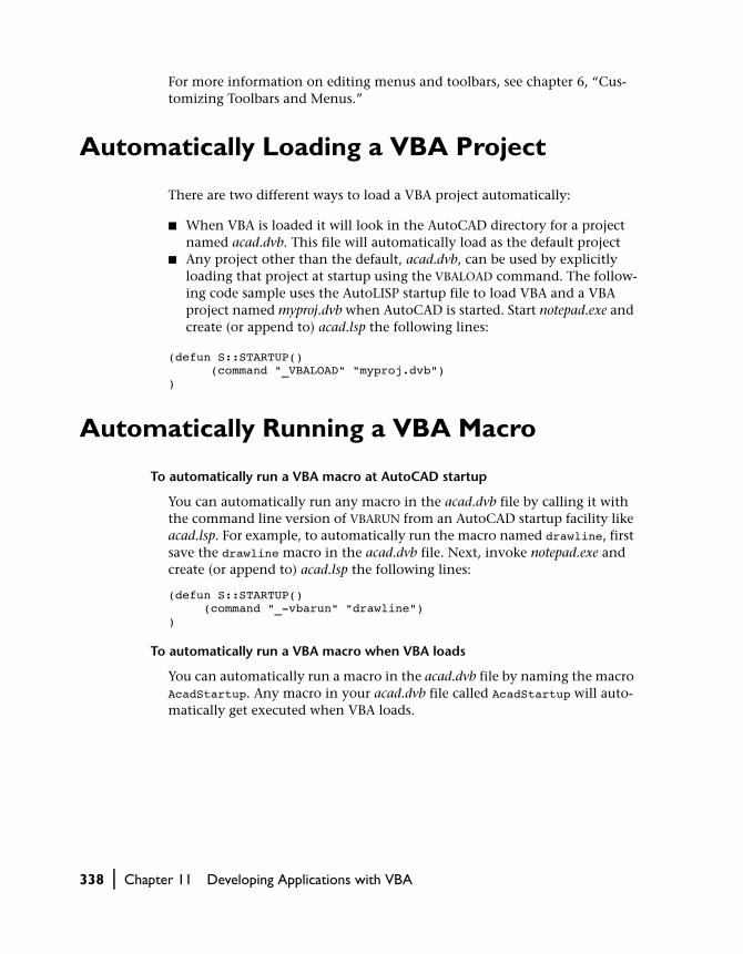
For more information on editing menus and toolbars, see chapter 6, “Cus-tomizing Toolbars and Menus.”
Automatically Loading a VBA Project
There are two different ways to load a VBA project automatically:
■ When VBA is loaded it will look in the AutoCAD directory for a project named acad.dvb. This file will automatically load as the default project
■ Any project other than the default, acad.dvb, can be used by explicitly loading that project at startup using the VBALOAD command. The follow-ing code sample uses the AutoLISP startup file to load VBA and a VBA project named myproj.dvb when AutoCAD is started. Start notepad.exe and create (or append to) acad.lsp the following lines:
(defun S::STARTUP() (command "_VBALOAD" "myproj.dvb"))
Automatically Running a VBA Macro
To automatically run a VBA macro at AutoCAD startup
You can automatically run any macro in the acad.dvb file by calling it with the command line version of VBARUN from an AutoCAD startup facility like acad.lsp. For example, to automatically run the macro named drawline, first save the drawline macro in the acad.dvb file. Next, invoke notepad.exe and create (or append to) acad.lsp the following lines:
(defun S::STARTUP() (command "_-vbarun" "drawline"))
To automatically run a VBA macro when VBA loads
You can automatically run a macro in the acad.dvb file by naming the macro AcadStartup. Any macro in your acad.dvb file called AcadStartup will auto-matically get executed when VBA loads.
338 | Chapter 11 Developing Applications with VBA

Automatically Opening the VBA IDE Whenever a Project Is Loaded
There is an option on the Open VBA Project dialog box that allows you to open the IDE automatically. Simply check the box “Open Visual Basic Editor” found in the lower-left side of the dialog box and the VBA IDE will open auto-matically whenever a VBA project is loaded. This option will remain set until you turn it off again.
NOTE To access the Open VBA Project dialog box, enter VBALOAD at the com-mand line. The dialog box will open and allow you to choose a project to load. If you do not see the Open VBA Project dialog box, it is most likely because the system variable FILEDIA is turned off. This system variable turns on and off the display of dialog boxes. To turn FILEDIA back on, set it to 1.
Working in a Zero Document State
A zero document state is when there are no open drawings in AutoCAD. There are several important considerations to keep in mind when you are working with VBA in a zero document state:
■ The ThisDrawing object is undefined in a zero document state. Any attempt to use ThisDrawing will result in an error
■ Objects that are document dependent are also not defined in a zero docu-ment state. Document dependent objects are those objects that fall below the Document object in the AutoCAD object model. Working with non-document dependent objects, such as the Application or MenuBar objects, is allowed
■ AutoCAD does not have a command line in a zero document state. Any attempt to access the AutoCAD command line while AutoCAD is in a zero document state will result in an error
Automatically Opening the VBA IDE Whenever a Project Is Loaded | 339

Distributing Your Application
VBA applications can be distributed two different ways:
■ Embedded in an AutoCAD drawing■ Stored in a VBA project file
You must choose a distribution option that is appropriate for your applica-tion. Applications that are applicable to the current drawing, and do not access other drawings, are often embedded in the drawing. By embedding the application in the drawing, you can always be sure the application is loaded, and therefore available to the user whenever the drawing is open.
Applications that are used by many people, are updated frequently, need to open and close other drawings, or are not used frequently you may want to store in a VBA project file. In this way, there is one central location for the application, and everyone can be sure to use the latest version.
For more information on embedded projects and VBA project files, see “Understanding Embedded and Global VBA Projects” on page 26.
Distributing Visual Basic Applications
Visual Basic applications, or any other out-of-process application, cannot be stored within an AutoCAD drawing. These applications are compiled into standalone executables (EXE) and can be run from AutoCAD using the APPLOAD command.
340 | Chapter 11 Developing Applications with VBA

In This Chapter
Interacting with Other Applications, Databases, and Windows APIs
12■ Interacting with Visual LISP
Applications
■ Interacting with Other Windows Applications
■ Using Data Access Objects (DAO) to Access Database Information
■ Accessing Windows APIs from VBA
ActiveX technology allows you to exchange informa-
tion easily with other AutoCAD applications and other
ActiveX-enabled applications such as Microsoft Excel or
Microsoft Word. This chapter examines some of the
basic procedures for interacting with other applications.
341

Interacting with Visual LISP Applications
Visual LISP applications have access to the entire range of ActiveX objects. They can call ActiveX methods, and set and retrieve ActiveX properties. In addition, Visual LISP applications can also run VBA macros through the VBARUN command.
ActiveX and VBA applications can execute Visual LISP applications through the SendCommand method. This method allows ActiveX and VBA applica-tions to send a command to the AutoCAD command line.
For more information on accessing ActiveX objects through Visual LISP, see the Visual LISP Developer’s Guide.
Interacting with Other Windows Applications
AutoCAD ActiveX technology allows you to exchange information easily with other ActiveX-enabled applications such as Microsoft Excel or Microsoft Word. This capability allows you to collect, store, and present AutoCAD information in formats other than the AutoCAD drawing. You can also read information from these applications back into AutoCAD to direct the creation or manipulation of AutoCAD objects. An example of using this technology is to create a bill of materials as a Microsoft Excel spreadsheet from the objects in an AutoCAD drawing.
You have already learned how to write code using the AutoCAD ActiveX Object Model. Exchanging information with other ActiveX-enabled applica-tions involves simply referencing the other applications’ ActiveX Object Model and writing the code necessary to utilize their objects.
NOTE This chapter provides only a brief introduction to the capabilities of cross-application programming. This material is not AutoCAD specific, and as such it is discussed in both Microsoft documentation and independent program-ming guides. It is also covered extensively in the “VBA Foundations for AutoCAD” and “VBA Solutions for AutoCAD” courses provided by Autodesk.
342 | Chapter 12 Interacting with Other Applications, Databases, and Windows APIs

There are three basic steps for exchanging information across ActiveX Object Models
1 Reference the other applications’ ActiveX Object Model.
This will make your code aware of the names and relationships of the objects in the other Object Model.
2 Create an instance of the other application.
This will create valid objects for (instantiate) the basic objects in the other Object Model.
3 Write your code utilizing both the AutoCAD Object Model and the other applications’ Object Model.
This is where the exchange of data takes place.
Referencing the ActiveX Object Library of Other Applications
To write code that accesses another application, you must instruct VBA to make the objects in the other application available to you. You do this by set-ting a reference in the other application’s object library. This is a file on your computer where all the objects, methods, properties, constants, and events for that application are defined.
You make a reference to an object library through the VBA IDE. In the VBA IDE, under the Tools menu, there is a menu option called References. This menu option will bring up a dialog box that lists all of the object libraries VBA finds on your system. To make a reference to a library, simply select the library from the list. Libraries with check boxes that are selected are already referenced in the current project. For example, to add the Microsoft Excel object library, select the Microsoft Excel object library entry in the list.
To make a reference to another application’s object library
1 In the VBA IDE, open the Tools menu and select the References menu option.
2 Find and select the entry in the list of Available References for the application you want to access.
3 Select OK to close the dialog box with your changes.
Once you have created a reference to another application’s object library, you can use the VBA Object Browser to view a list of the application’s objects.
Interacting with Other Windows Applications | 343

NOTE You must set the reference for each VBA project that will use this Object Model. Setting the reference for one project won’t automatically set it for another project. This is for performance reasons.
Creating an Instance of the Other Application
Once you have referenced an application’s object library you must create an instance of the application. This is just a fancy way of saying you need to start the other application programmatically so your code will have valid objects to work with.
To do this, first declare a variable that will represent the other application. You do this the same way as built-in objects, by using a Dim statement. You should qualify the type of application in your Dim statement. For example, this Dim statement declares an object variable of type Excel.Application:
Dim ExcelAppObj as Excel.Application
After you declare the variable, use the Set statement with the New keyword to set the variable equal to a running instance of the application. For exam-ple, the following Set statement sets the variable declared above equal to the Excel application. The New keyword starts a new session of Excel.
Set ExcelAppObj = New Excel.Application
NOTE Some applications allow only one running instance of the application at a time. Using the New keyword on such an application will establish a reference to the existing instance and will not launch a new session of the application.
Programming with Objects from Other Applications
Now that you have referenced the object library and created a new instance of the application, you can create and manipulate objects in that application. All the objects, methods, and properties defined by the Object Model are available to you. For example, using the variable declarations from the previ-ous section, the following line of code makes the Excel session visible to the user:
ExcelAppObj.Visible = TRUE
344 | Chapter 12 Interacting with Other Applications, Databases, and Windows APIs

You should familiarize yourself with the Object Model of the application you are writing code for. You can use the VBA Object Browser or the application’s help file to learn about any Object Model you are referencing.
Quitting the Other ApplicationWhen you start an application programmatically it takes up memory in the computer. You should quit the application when you have finished using it so system resources can be freed up.
Although each Object Model is different, most have a Quit method from the Application object that can be used to close the application cleanly. For example, using the variable declarations from the previous section, the fol-lowing line of code will quit Excel:
ExcelAppObj.Application.Quit
NOTE Destroying or going beyond the scope of the object variable does not necessarily cause the application to terminate. You should always quit the appli-cation using the appropriate method to assure proper memory cleanup.
Listing AutoCAD attributes on an Excel spreadsheet
This subroutine finds all the block references in the current drawing. It then finds the attributes attached to those block references and lists them in an Excel spreadsheet.
To run this example
1 Open a drawing containing block references with attributes. (The sample drawing sample/activeX/attrib.dwg contains such block references.)
2 Open the VBA IDE using the AutoCAD VBAIDE command.
3 Using the Tools ➤ References menu option in the VBA IDE, select Microsoft Excel 8.0 Object Model.
4 Copy this subroutine into a VBA Code window and run it.
Sub Ch12_Extract() Dim Excel As Excel.Application Dim ExcelSheet As Object Dim ExcelWorkbook As Object Dim RowNum As Integer Dim Header As Boolean Dim elem As AcadEntity Dim Array1 As Variant Dim Count As Integer
Interacting with Other Windows Applications | 345

’ Launch Excel. Set Excel = New Excel.Application ’ Create a new workbook and find the active sheet. Set ExcelWorkbook = Excel.Workbooks.Add Set ExcelSheet = Excel.ActiveSheet ExcelWorkbook.SaveAs "Attribute.xls" RowNum = 1 Header = False ’ Iterate through model space finding ’ all block references. For Each elem In ThisDrawing.ModelSpace With elem ’ When a block reference has been found, ’ check it for attributes If StrComp(.EntityName, "AcDbBlockReference", 1) _ = 0 Then If .HasAttributes Then ’ Get the attributes Array1 = .GetAttributes ’ Copy the Tagstrings for the ’ Attributes into Excel For Count = LBound(Array1) To UBound(Array1) If Header = False Then If StrComp(Array1(Count).EntityName, _ "AcDbAttribute", 1) = 0 Then ExcelSheet.Cells(RowNum, _ Count + 1).value = _ Array1(Count).TagString End If End If Next Count RowNum = RowNum + 1 For Count = LBound(Array1) To UBound(Array1) ExcelSheet.Cells(RowNum, Count + 1).value _ = Array1(Count).textString Next Count Header = True End If End If End With Next elem Excel.Application.QuitEnd Sub
346 | Chapter 12 Interacting with Other Applications, Databases, and Windows APIs

Using Data Access Objects (DAO) to Access Database Information
Data access objects (DAO) let you work with data in a database. More specif-ically, using DAO you can access any database that is powered by the Microsoft Jet database engine. This includes
■ Desktop databases, such as Access, dBase, FoxPro, and Paradox■ ODBC databases, such as Microsoft SQL Server and Oracle®
DAO gives you complete control over the database from your VBA code so you can
■ Create a new database or modify the structure of an existing database■ Add tables to a database, define relationships between tables, and create
and run queries■ Add, edit, or delete records■ Secure your database
There are three basic steps for using DAO in your VBA code
1 Reference the Microsoft DAO Object Library.
2 Open the database you want to work with.
This will create valid objects for (instantiate) objects in the DAO.
3 Write your code utilizing both the AutoCAD Object Model and the DAO Object Model.
NOTE This chapter provides only a brief introduction to the capabilities of programming with DAO. This material is not AutoCAD specific, and as such it is discussed in both Microsoft documentation and independent programming guides. It is also covered extensively in the “VBA Foundations for AutoCAD” and “VBA Solutions for AutoCAD” courses provided by Autodesk.
Using Data Access Objects (DAO) to Access Database Information | 347

Referencing the DAO Object Library
To write code that accesses the DAO, you must instruct VBA to make the objects in the DAO available to you. You do this by setting a reference to the DAO Object Library.
To make a reference to another application’s object library
1 In the VBA IDE, open the Tools menu and select the References menu option.
2 Find and select the entry Microsoft DAO Object Library.
3 Select OK to close the dialog box with your changes.
Once you create a reference to the DAO Object Library, you can use the VBA Object Browser to view the objects in the DAO Object Library.
NOTE You must set a reference to this library for each VBA project that will use the DAO. Setting the reference for one project won’t automatically set it for another project. This is for performance reasons.
Opening the Database
To work with data in a database, you need to open the database from VBA. To open a database, use the OpenDatabase method of the default Workspace object in the DAO Object Model. The following code opens a database named X.MDB:
Dim db As DatabaseSet db = DBEngine.Workspaces(0).OpenDatabase("C:\X.MDB")
This code refers to the DBEngine object, then to the default Workspace object in the DAO Object Model. It opens a database on the default Workspace object and assigns the database to a database object variable.
Programming with the DAO Object Model
Now that you have referenced the DAO Object Library and created and opened a database, you can edit or query the data in the database. All the objects, methods, and properties defined by the DAO Object Model are avail-able to you.
348 | Chapter 12 Interacting with Other Applications, Databases, and Windows APIs

Most of the work you will be doing with the data in a database will involve the DAO Recordset object. This object represents a set of rows returned by a table, a select query (either a query object or an SQL string), or even another Recordset object. This object is the basis of working with data programmati-cally, and will figure prominently in any code you write that manipulates data.
You should familiarize yourself with the DAO Object Model. You can use the VBA Object Browser or the Microsoft DAO Help file to learn about the DAO Object Model. The DAO reference also contains example code to help you get started.
Accessing Windows APIs from VBA
The Windows API procedures are available to most Windows applications. These procedures allow you to expand the capabilities of your application.
Through the Windows APIs you can obtain information about the current system, such as which other programs are installed or running on the system, where information is located on a system, and what the current control set-tings are for the system. You can also access joystick, multimedia, and sound controls. These tasks represent but a few of the many capabilities provided by the Windows APIs.
To use a Windows API, you must first declare the API in your application. This is done through the Visual Basic Declare statement. The Declare state-ment requires several pieces of information:
■ The name of the dynamic link library (DLL) containing the procedure you want to use
■ The name of the procedure as it appears in the DLL■ The name of the procedure as you want to use it in your application■ The parameters the procedure expects to receive■ The return value data type (if the procedure you are calling is a function)
You can place the Declare statement in any of your VBA modules. If you place it in a standard module, the procedure will be available to any module in your application, unless you limit its scope by using the keyword Private. If you place the Declare statement in a class or form module, the procedure will only be available in that module. Once a procedure has been declared, you can call that procedure as you would any other procedure in your application.
Accessing Windows APIs from VBA | 349

Getting a Declare statement just right is a difficult skill to learn. Getting a Declare statement wrong is easy, but it often comes with dire consequences. Be sure to save any information in active applications before you try out a new Declare statement.
To help you with your Declare statements, Microsoft provides a file listing of many of the declarations most commonly used. The file is called Win32api.txt and comes with Visual Basic and Office. You can search this file for the procedure you need and copy the Declare statement provided into your code.
The Microsoft VBA documentation contains more information on the Declare statement and an example of its use. The Microsoft Windows API Reference is available as part of the Mircrosoft Developer Network CD sub-scription and provides a reference to all the available procedures in the Windows APIs. Dan Appleman’s book Visual Basic Programmer’s Guide to the Win32 API is also an excellent resource directed at the Visual Basic programmer.
350 | Chapter 12 Interacting with Other Applications, Databases, and Windows APIs

In This Chapter
Designing the Garden Path—An ActiveX/VBA Tutorial
13■ Checking Your Environment
■ Defining the Goal
■ Writing Your First Function
■ Getting Input
■ Drawing the Path Outline
■ Drawing the Tiles
■ Tying It All Together
■ Stepping through the Code
■ Executing the Macro
■ Adding a Dialog Box Interface
This tutorial shows you how to add a new macro to
AutoCAD, explains how ActiveX and Visual Basic for
Applications (VBA) work, and shows you how best to
use the power of these technologies. The tutorial is ori-
ented to landscape architecture, but the concepts you
will learn are relevant to any application area.
This tutorial is designed for the proficient AutoCAD user
who is a novice VBA programmer.
351

Checking Your Environment
To perform the required tasks, you will need to install the VBA environment within AutoCAD. The VBA environment is installed automatically with both the standard and full options of the AutoCAD installation program. If you selected the custom option, the VBA environment may not be installed.
To test if the VBA environment is installed
1 Start AutoCAD.
2 On the command line, enter: VBAIDE.
3 If the VBA interactive development environment opens, then the VBA envi-ronment is installed. If you receive the message “AutoCAD VBA is not cur-rently installed,” then the VBA environment is not installed.
To install the VBA environment
1 Exit out of AutoCAD.
2 Run the AutoCAD setup program setup.exe.
3 Select Add to add new components to your current installation.
4 Check the VBA Support option.
5 Select Next to proceed with the installation.
6 Confirm your settings by selecting Next again.
7 Once the setup program has finished, start AutoCAD.
8 On the command line, enter VBAIDE. The VBA interactive development environment will open, and you are now ready to begin the tutorial.
Defining the Goal
Your goal in this tutorial is to develop a new macro for AutoCAD that draws a garden path and fills it with circular concrete tiles. Your new macro will have the following prompt sequence:
Command: gardenpathStart point of path: The user will specify the start pointEndpoint of path: The user will specify the endpointHalf width of path: The user will specify a numberRadius of tiles: The user will specify a numberSpacing between tiles: The user will specify a number
352 | Chapter 13 Designing the Garden Path—An ActiveX/VBA Tutorial

Your macro will first prompt the user to enter the start point and endpoint to specify the centerline of a path. Next, prompt the user to enter the half width of the path and the radius of the circular tiles. Finally, the user will enter the spacing between the tiles. You are using the half width of the path rather than the full width because it is easier to visualize the half width from the centerline of the path.
Writing Your First Function
You will develop this macro using a series of functions and subroutines. Many subroutines require the manipulation of angles. Because ActiveX spec-ifies angles in radians but most users think of angles in terms of degrees, begin by creating a function that converts degrees to radians.
If the VBA IDE is not already open, open it by entering the command VBAIDE.
In the VBA IDE, open the Code window by selecting the Code menu option from the View menu, or by pressing F7.
Converting degrees to radians
Enter the following code in the Code window, after the line Option Explicit:
Const pi = 3.14159’ Convert angle in degrees to radiansFunction dtr(a As Double) As Double dtr = (a / 180) * piEnd Function
You will notice that as soon as you enter a return after the line Function dtr(a As Double) As Double, VBA automatically fills in the End Function line for you. This is normal for the VBA environment—it does this to make sure that all subroutines and functions have an associated End statement.
Now look at the code. First, the constant pi is defined as the value 3.14159. This allows you to use the word pi instead of typing 3.14159 each time you need to use the value.
Next, you are defining a function called dtr (short for degrees to radians). The function dtr takes one argument, a, which is the angle in degrees. The result is obtained by dividing the angle in degrees by 180, and then multiply-ing this value by pi. The line that begins with a single quote is a comment; VBA ignores all text on a line after a single quote.
Writing Your First Function | 353

This function can now be used in other subroutines throughout your project.
Now is a good time to save your work. Select the File ➤ Save menu option. The project has the default name of project.dvb, but you will be given a chance to give it another name. Call the project gardenpath.dvb.
Calculating the distance between two points
Next add a function to calculate the distance between points. Enter the fol-lowing code after the dtr function:
’ Calculate distance between two pointsFunction distance(sp As Variant, ep As Variant) _ As Double Dim x As Double Dim y As Double Dim z As Double x = sp(0) - ep(0) y = sp(1) - ep(1) z = sp(2) - ep(2) distance = Sqr((Sqr((x ^ 2) + (y ^ 2)) ^ 2) + (z ^ 2))End Function
Save your work.
Getting Input
This macro asks the user where to draw the path, how wide to make the path, how large the concrete tiles are, and how closely to space those tiles. You will define a subroutine that asks the user for all of these items and then com-putes various numbers to use in the rest of the macro.
In this subroutine you will use the user input methods found in the Utility object.
Declaring Variables
The next subroutine will use several global variables. All global variables need to be declared before the subroutine can access them.
354 | Chapter 13 Designing the Garden Path—An ActiveX/VBA Tutorial

Declaring global variables
In the VBA IDE, enter the following code in the Code window, immediately after the line Const pi = 3.14159:
’ Variables used to store garden path parametersPrivate sp(0 To 2) As DoublePrivate ep(0 To 2) As DoublePrivate hwidth As DoublePrivate trad As DoublePrivate tspac As DoublePrivate pangle As DoublePrivate plength As DoublePrivate totalwidth As DoublePrivate angp90 As DoublePrivate angm90 As Double
Now look at the two drop-down lists at the top of the Code window. These lists are called the Object Box and the Procedure/Event Box and currently dis-play the terms (General) and (Declarations), respectively. These lists display the current section of the code you are working in, and enable you to move quickly to a different section by simply selecting one from the list. The (Dec-larations) section is the appropriate place to declare variables that you will use in more than one subroutine.
Notice the line Option Explicit at the top of the (Declarations) section. When Option Explicit appears in a module, you must explicitly declare all variables using the Dim, Private, Public, ReDim, or Static statements. If you attempt to use an undeclared variable name, an error occurs. If you don’t use the Option Explicit statement, all undeclared variables are of Variant type unless the type is otherwise specified. It is recommended that you always use the Option Explicit statement to avoid incorrectly typing the name of an existing variable or to avoid confusion in code where the scope of the vari-able is not clear.
Getting Input | 355

Entering the gpuser Subroutine
The gpuser subroutine will prompt the user for all the information necessary to construction the garden path.
Prompting for user input
Enter the following code after the distance function:
’ Acquire information for garden pathPrivate Sub gpuser() Dim varRet As Variant varRet = ThisDrawing.Utility.GetPoint( _ , "Start point of path: ") sp(0) = varRet(0) sp(1) = varRet(1) sp(2) = varRet(2) varRet = ThisDrawing.Utility.GetPoint( _ , "Endpoint of path: ") ep(0) = varRet(0) ep(1) = varRet(1) ep(2) = varRet(2) hwidth = ThisDrawing.Utility. _ GetDistance(sp, "Half width of path: ") trad = ThisDrawing.Utility. _ GetDistance(sp, "Radius of tiles: ") tspac = ThisDrawing.Utility. _ GetDistance(sp, "Spacing between tiles: ") pangle = ThisDrawing.Utility.AngleFromXAxis( _ sp, ep) totalwidth = 2 * hwidth plength = distance(sp, ep) angp90 = pangle + dtr(90) angm90 = pangle - dtr(90)End Sub
Here you have defined a subroutine called gpuser. The subroutine takes no arguments and asks the user for all of the desired information.
The line Dim varRet As Variant simply declares the variable varRet. Because this variable is used only in this subroutine, it can be declared here locally, instead of in the (Declarations) section of the code.
The next line, varRet = ThisDrawing.Utility.GetPoint( , "Start point of path: "), calls the GetPoint method. The underscore displayed in the middle of this code in the previous subroutine tells VBA to continue reading the next line as if it were all on the same line. The underscore is unnecessary; you can eliminate it by placing the code all on one line. However, the under-score makes long lines of code easier to read.
356 | Chapter 13 Designing the Garden Path—An ActiveX/VBA Tutorial

To access the GetPoint method, you must first go through the ThisDrawing object that represents the current drawing. After entering ThisDrawing you enter a period (.), which means that you are going to access something within that object. After you type the period, you enter Utility and another period. Once again, you are going to access something within the Utility object. Finally, enter GetPoint, which is the name of the method you are calling.
The GetPoint method takes two parameters. The first parameter is optional and won’t be used. Leave the parameter blank and simply input a comma to mark its spot. The second parameter is the prompt, which is also optional. For this parameter you have entered a string prompting the user to enter the start point. The point the user enters is put into the varRet variable. The next three lines of the subroutine copy the point returned by the user into the sp array.
The endpoint is returned in the same manner.
The GetDistance method is used to obtain the half width of the path (hwidth), the tile radius (trad), and the spacing between the tiles (tspac). The GetDistance method takes two parameters. The first is a base point. For this value you supply the start point. The second parameter is the prompt, for which you provide a string prompting the user for the appropriate input. The interesting thing about the GetDistance method is that it can return either a value entered on the command line or the distance between a point selected in AutoCAD and the start point.
The subroutine goes on to calculate several variables used later in the macro. The pangle variable is set to the angle from the start point to the endpoint and is found by using the AngleFromXAxis method. The width of the path is found by multiplying the half width by two. The plength variable is set to the length of the path and is found using the distance function you entered earlier. Finally, calculate and save the angle of the path plus and minus 90 degrees in angp90 and angm90, respectively.
The following illustration shows how the variables obtained by gpuser spec-ify the dimensions of the path.
Getting Input | 357

Save your work.
Drawing the Path Outline
Now that you have acquired the location and width of the path, you can draw its outline.
Drawing the outline of the garden path
Add the following code below the gpuser subroutine:
’ Draw outline of pathPrivate Sub drawout() Dim points(0 To 9) As Double Dim pline As AcadLWPolyline Dim varRet As Variant varRet = ThisDrawing.Utility.PolarPoint( _ sp, angm90, hwidth) points(0) = varRet(0) points(1) = varRet(1) points(8) = varRet(0) points(9) = varRet(1) varRet = ThisDrawing.Utility.PolarPoint( _ varRet, pangle, plength)
358 | Chapter 13 Designing the Garden Path—An ActiveX/VBA Tutorial

points(2) = varRet(0) points(3) = varRet(1) varRet = ThisDrawing.Utility.PolarPoint( _ varRet, angp90, totalwidth) points(4) = varRet(0) points(5) = varRet(1) varRet = ThisDrawing.Utility.PolarPoint( _ varRet, pangle + dtr(180), plength) points(6) = varRet(0) points(7) = varRet(1) Set pline = ThisDrawing.ModelSpace. _ AddLightWeightPolyline(points)End Sub
This subroutine draws the outline of the path using the AddLightweightPolyline method. This method takes one parameter: an array of points that make up the polyline. You must find all the points that make up the polyline object and place them into an array in the order they are to be drawn. For this polyline, the points needed are the corners of the path.
To find the corners of the path, use the PolarPoint method. This method finds a point that is a given angle and distance from a base point. Begin with the start point (sp) and find the first corner of the path, working in a coun-terclockwise direction. This corner will be at a distance of half the width of the path (hwidth) and at -90 degrees from the path angle. Because you want to draw a closed rectangle for the path, this point becomes the first and last point in the array. Hence, the X and Y coordinates returned from the PolarPoint method are moved into the first and last positions in the points array.
The remaining corners of the path are found in the same manner using the length and width of the path (plength and width), and the angle of the path. Every time the PolarPoint method is called, the coordinates returned (varRet) are copied into the points array.
Once all the corners have been identified in the points array, the AddLight-weightPolyline method is called. Notice that this method is called from the ModelSpace object. If you were to run this macro, you would also notice that the polyline is not yet visible in AutoCAD. The polyline will not become vis-ible until we update the display, which we will do later.
Drawing the Path Outline | 359

Drawing the Tiles
Now that you have developed the user input subroutine, along with the sub-routine to draw the outline, you are ready to fill the path with circular tiles. This task requires some geometry.
Filling in the path with circular tiles
In the VBA IDE, enter the following code in the Code window, after the drawout subroutine:
’ Place one row of tiles the given distance along path’ and possibly offset itPrivate Sub drow(pd As Double, offset As Double) Dim pfirst(0 To 2) As Double Dim pctile(0 To 2) As Double Dim pltile(0 To 2) As Double Dim cir As AcadCircle Dim varRet As Variant varRet = ThisDrawing.Utility.PolarPoint( _ sp, pangle, pd) pfirst(0) = varRet(0) pfirst(1) = varRet(1) pfirst(2) = varRet(2) varRet = ThisDrawing.Utility.PolarPoint( _ pfirst, angp90, offset) pctile(0) = varRet(0) pctile(1) = varRet(1) pctile(2) = varRet(2) pltile(0) = pctile(0) pltile(1) = pctile(1) pltile(2) = pctile(2) Do While distance(pfirst, pltile) < (hwidth - trad) Set cir = ThisDrawing.ModelSpace.AddCircle( _ pltile, trad) varRet = ThisDrawing.Utility.PolarPoint( _ pltile, angp90, (tspac + trad + trad)) pltile(0) = varRet(0) pltile(1) = varRet(1) pltile(2) = varRet(2) Loop varRet = ThisDrawing.Utility.PolarPoint( _ pctile, angm90, tspac + trad + trad) pltile(0) = varRet(0) pltile(1) = varRet(1) pltile(2) = varRet(2)
360 | Chapter 13 Designing the Garden Path—An ActiveX/VBA Tutorial

Do While distance(pfirst, pltile) < (hwidth - trad) Set cir = ThisDrawing.ModelSpace.AddCircle( _ pltile, trad) varRet = ThisDrawing.Utility.PolarPoint( _ pltile, angm90, (tspac + trad + trad)) pltile(0) = varRet(0) pltile(1) = varRet(1) pltile(2) = varRet(2) LoopEnd Sub’ Draw the rows of tilesPrivate Sub drawtiles() Dim pdist As Double Dim offset As Double pdist = trad + tspac offset = 0 Do While pdist <= (plength - trad) drow pdist, offset pdist = pdist + ((tspac + trad + trad) * Sin(dtr(60))) If offset = 0 Then offset = (tspac + trad + trad) * Cos(dtr(60)) Else offset = 0 End If LoopEnd Sub
To understand how these subroutines work, refer to the following illustra-tion. The subroutine drow draws a row of tiles at a given distance along the path specified by its first argument, and offsets the row perpendicular to the path by a distance specified by its second argument. You want to offset the tiles on alternate rows to cover more space and make a more pleasing arrangement.
The drow subroutine finds the location for the first row by using the PolarPoint method to move along the path by the distance specified by the first argument. The subroutine then uses the PolarPoint method again to move perpendicularly to the path for the offset. The subroutine uses the While statement to continue to draw circles until the edge of the path is
60 degrees
30 degrees
TSPAC + 2 * TRAD
Drawing the Tiles | 361

encountered. The PolarPoint method in the first While statement moves on to the next tile location by spacing a distance of two tile radii (trad) and one intertile space (tspac). A second while loop then draws the tiles in the row in the other direction until the other edge is encountered.
The drawtiles subroutine calls drow repeatedly to draw all the tile rows. The subroutine While loop steps along the path, calling drow for each row. Tiles in adjacent rows form equilateral triangles, as shown in the previous illustra-tion. The edges of these triangles are equal to twice the tile radius plus the spacing between the tiles. Therefore, by trigonometry, the distance along the path between rows is the sine of 60 degrees multiplied by this quantity, and the offset for odd rows is the cosine of 60 degrees multiplied by this quantity.
The If statement is used in drawtiles to offset every other row. If the offset is equal to 0, set it to the spacing between the centers of tiles multiplied by the cosine of 60 degrees, as explained earlier. If the offset is not equal to 0, set it to 0. This alternates the offset on the rows as you want.
Save the file.
Tying It All Together
Finally, you are ready to combine all the subroutines together into the macro you will call gardenpath.
Creating the gardenpath executable subroutine
In the VBA IDE, enter the following code in the Code window, after the drawtiles subroutine:
’ Execute command, calling constituent functionsSub gardenpath() Dim sblip As Variant Dim scmde As Variant gpuser sblip = ThisDrawing.GetVariable("blipmode") scmde = ThisDrawing.GetVariable("cmdecho") ThisDrawing.SetVariable "blipmode", 0 ThisDrawing.SetVariable "cmdecho", 0 drawout drawtiles ThisDrawing.SetVariable "blipmode", sblip ThisDrawing.SetVariable "cmdecho", scmdeEnd Sub
362 | Chapter 13 Designing the Garden Path—An ActiveX/VBA Tutorial

The path subroutine calls gpuser to gather the necessary input. The GetVariable method is then used to obtain the current values of the BLIPMODE and CMDECHO system variables, and saves these values as sblip and scmde. The subroutine then uses the SetVariable method to set both of these system variables to 0, thereby disabling blips and command echoing. Next, the path is drawn using the drawout and drawtiles subroutines. Finally, the SetVariable method is used to reset the system variables to their original values.
You may notice that this is the only subroutine you have entered that did not begin with a Private keyword, which ensures the subroutine can only be called from within the current module. Because the gardenpath subroutine must be available to the user, you should omit the Private keyword.
Stepping through the Code
Now run the macro, stepping through the code as it executes.
From the AutoCAD Tools menu, select Macro ➤ Run Macro. From the Macros dialog box select ThisDrawing.gardenpath and press the Step button.
The VBA IDE will be brought to the front of the screen, with the first line of the gardenpath macro highlighted. The highlighted line is the line of code that is about to be executed. To execute the line, press F8. The next line of code to be executed is the gpuser subroutine. To step into the gpuser subrou-tine, press F8 again.
Now you are at the beginning of the gpuser routine. Pressing F8 one more time will highlight the first GetPoint method. Before you execute this line, open the Locals window by selecting View ➤ Locals Window. This window is displayed at the bottom of the VBA IDE. All the local variables and their values will be displayed in the locals window while the macro is executing.
Now press F8 to execute the GetPoint method. You will notice that the high-light disappears and no new code is presented. This is because the GetPoint method is waiting for the user to enter a point in AutoCAD. Switch back to the AutoCAD window. You will see the prompt you specified in the GetPoint call on the command line. Enter a point.
At this time, control goes back to the macro. Switch back to the VBA IDE. You will now see that the line following the call to the GetPoint method is high-lighted. Continue stepping through the code by pressing F8. Remember to switch back to the AutoCAD window when you are entering information.
Stepping through the Code | 363

Executing the Macro
You don’t have to step through the code whenever you run the macro. You can run the macro from the Tools menu by selecting Macro ➤ Run Macro, then using the Run button instead of the Step button. This allows you to see the flow of execution the way your user will see it. Run the macro from AutoCAD, entering the following values:
Tools ➤ Macro ➤ Run Macro:ThisDrawing.gardenpathStart point of the path: 2, 2Endpoint of the path: 9, 8Half width of the path: .2Radius of tiles: .2Spacing between tiles: .1
This example should draw a garden path as shown in the following figure:
You can experiment with the gardenpath macro by specifying the various inputs using the mouse and the keyboard.
364 | Chapter 13 Designing the Garden Path—An ActiveX/VBA Tutorial

Adding a Dialog Box Interface
You use the VBA IDE to add dialog boxes to your VBA macro.
Your new gardenpath macro accepts its input at the command line. You can easily add a dialog box interface to this macro. Dialog boxes are useful for giv-ing a user choices from a number of options.
Because the gardenpath macro currently has very few options, you should add a few more features. You will add a new feature that will enable your users to specify the shape of the tiles in the path.
You should start by copying the finished version of gardenpath.dvb to another file, gpdialog.dvb.
To copy the file
1 Save your current project in the VBA IDE.
2 Using the SaveAs command in the VBA IDE, save the project under the name gpdialog.dvb.
Creating the Dialog Box
Dialogs boxes are created in the VBA IDE using forms.
The dialog box you create will contain two option buttons (if you select one, the other is cleared) for choosing the tile shape: circle or polygon. The dialog box will also contain three text edit boxes for entering the following numeric values: the radius of the tiles, the spacing between the tiles, and the number of sides on the tile (which is available only if the Polygon option button is selected).
Adding a Dialog Box Interface | 365

To create a dialog box from the VBA IDE
1 Open a new form from the Insert menu by selecting the User Form option. This command opens two windows. The first is a toolbox containing all the controls available to create your dialog box. The second is a blank form where you will place the controls you want.
2 One by one, select and drag the following controls from the toolbox and place them on the user form. You should place two option buttons ( ), three labels ( ), three text boxes ( ), and two command buttons ( ), as illustrated on the following form:
3 Close the toolbox.
To set the properties for the radio button controls
1 On the user form, select the OptionButton1 control. In the Properties win-dow, change the following properties for OptionButton1. (If the Properties window isn’t open, use View ➤ Properties Window to open it):
(Name) = gp_poly
Caption = Polygon
ControlTipText = Polygon Tile Shape
Accelerator = P
2 On the user form, select the OptionButton2 control. In the Properties win-dow, change the following properties for OptionButton2:
(Name) = gp_circ
Caption = Circle
ControlTipText = Circle Tile Shape
Accelerator = I
366 | Chapter 13 Designing the Garden Path—An ActiveX/VBA Tutorial

To set the properties for the label controls
1 On the user form, select the Label1 control. In the Properties window, change the following properties for Label1:
(Name) = label_trad
Caption = Radius of tiles
TabStop = True
2 On the user form, select the Label2 control. In the Properties window, change the following properties for Label2:
(Name) = label_tspac
Caption = Space between tiles
TabStop = True
3 On the user form, select the Label3 control. In the Properties window, change the following properties for Label3:
(Name) = label_tsides
Caption = Number of sides
TabStop = True
To set the properties for the text edit box controls
1 On the user form, select the TextBox1 control. In the Properties window, change the following properties for TextBox1:
(Name) = gp_trad
2 On the user form, select the TextBox2 control. In the Properties window, change the following properties for TextBox2:
(Name) = gp_tspac
3 On the user form, select the TextBox3 control. In the Properties window, change the following properties for TextBox3:
(Name) = gp_tsides
Adding a Dialog Box Interface | 367

To set the properties for the command button controls and the form window
1 On the user form, select the CommandButton1 control. In the Properties window, change the following properties for CommandButton1:
(Name) = accept
Caption = OK
ControlTipText = Accept the options
Accelerator = O
Default = True
2 On the user form, select the CommandButton2 control. In the Properties window change the following properties for CommandButton2:
(Name) = cancel
Caption = Cancel
ControlTipText = Cancel the operation
Accelerator = C
3 On the user form, select the form itself by clicking on the background of the form, away from any control. In the Properties window, change the follow-ing properties for the form:
(Name) = gpDialogCaption = Garden Path
Your form should now look like this:
4 Save your work.
368 | Chapter 13 Designing the Garden Path—An ActiveX/VBA Tutorial
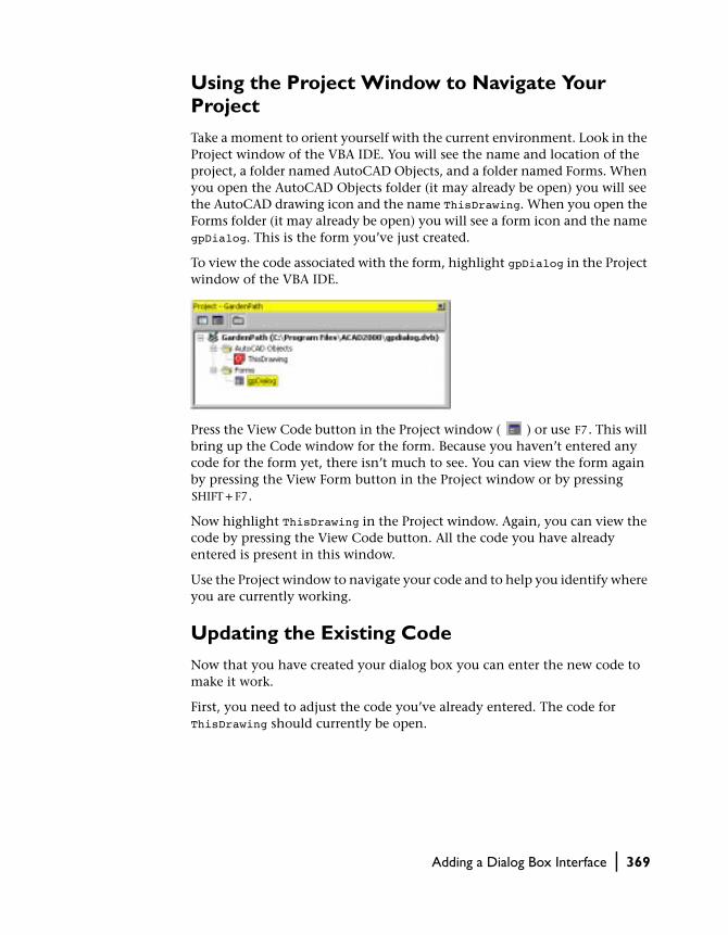
Using the Project Window to Navigate Your Project
Take a moment to orient yourself with the current environment. Look in the Project window of the VBA IDE. You will see the name and location of the project, a folder named AutoCAD Objects, and a folder named Forms. When you open the AutoCAD Objects folder (it may already be open) you will see the AutoCAD drawing icon and the name ThisDrawing. When you open the Forms folder (it may already be open) you will see a form icon and the name gpDialog. This is the form you’ve just created.
To view the code associated with the form, highlight gpDialog in the Project window of the VBA IDE.
Press the View Code button in the Project window ( ) or use F7. This will bring up the Code window for the form. Because you haven’t entered any code for the form yet, there isn’t much to see. You can view the form again by pressing the View Form button in the Project window or by pressing SHIFT + F7.
Now highlight ThisDrawing in the Project window. Again, you can view the code by pressing the View Code button. All the code you have already entered is present in this window.
Use the Project window to navigate your code and to help you identify where you are currently working.
Updating the Existing Code
Now that you have created your dialog box you can enter the new code to make it work.
First, you need to adjust the code you’ve already entered. The code for ThisDrawing should currently be open.
Adding a Dialog Box Interface | 369

Updating the global variables for use with a dialog box
Update the following lines in the Declarations section:
Public trad As Double ’ UpdatedPublic tspac As Double ’ UpdatedPublic tsides As Integer ’ AddPublic tshape As String ’ Add
Here you are updating the variable definitions for trad and tspac to be pub-lic instead of private. Private variables are available only in the module in which they are defined. That was OK before, but now the code in the form is going to need to access these variables, so the variables need to be changed to Public. Additionally, you have added two new variables, tsides and tshape. These variables contain the number of sides for the polygon tiles, and the user’s choice of tile shape: circle or polygon.
Updating gpuser subroutine for use with a dialog box
Go to the gpuser subroutine. Remove the two lines that get the radius of the tiles and the spacing between the tiles. This information is going to come from the form. Remove
trad = ThisDrawing.Utility. _ GetDistance(sp, "Radius of tiles: ")tspac = ThisDrawing.Utility. _ GetDistance(sp, "Spacing between tiles: ")
Add the lines that load and display the form. Add the following lines in place of the lines removed above:
Load gpDialog gpDialog.Show
The new gpuser subroutine should look like this:
’ Acquire information for garden pathPrivate Sub gpuser() Dim varRet As Variant varRet = ThisDrawing.Utility.GetPoint( _ , "Start point of path: ") sp(0) = varRet(0) sp(1) = varRet(1) sp(2) = varRet(2) varRet = ThisDrawing.Utility.GetPoint( _ , "Endpoint of path: ") ep(0) = varRet(0) ep(1) = varRet(1) ep(2) = varRet(2) hwidth = ThisDrawing.Utility. _ GetDistance(sp, "Half width of path: ")
370 | Chapter 13 Designing the Garden Path—An ActiveX/VBA Tutorial

Load GPDialog GPDialog.Show pangle = ThisDrawing.Utility.AngleFromXAxis( _ sp, ep) totalwidth = 2 * hwidth plength = distance(sp, ep) angp90 = pangle + dtr(90) angm90 = pangle - dtr(90)End Sub
Drawing tiles as circles or polygons
Next you need to add a subroutine that will draw either the circular tiles or the polygon tiles. Add the following code to the end of the code file:
’Draw the tile with the designated shapeSub DrawShape(pltile) Dim angleSegment As Double Dim currentAngle As Double Dim angleInRadians As Double Dim currentSide As Integer Dim varRet As Variant Dim aCircle As AcadCircle Dim aPolygon As AcadLWPolyline ReDim points(1 To tsides * 2) As Double ’Branch based on the type of shape to draw Select Case tshape Case "Circle" Set aCircle = ThisDrawing.ModelSpace. _ AddCircle(pltile, trad) Case "Polygon" angleSegment = 360 / tsides currentAngle = 0 For currentSide = 0 To (tsides - 1) angleInRadians = dtr(currentAngle) varRet = ThisDrawing.Utility.PolarPoint(pltile, _ angleInRadians, trad) points((currentSide * 2) + 1) = varRet(0) points((currentSide * 2) + 2) = varRet(1) currentAngle = currentAngle + angleSegment Next currentSide Set aPolygon = ThisDrawing.ModelSpace. _ AddLightWeightPolyline(points) aPolygon.Closed = True End SelectEnd Sub
This subroutine uses a Select Case statement to branch control of the pro-gram, based on the type of shape to draw. The tshape variable is used to determine the type of shape.
Adding a Dialog Box Interface | 371
Updating drow subroutine to draw the appropriate shape tile
Next, go to the drow subroutine. Find the two occurrences of the following line:
Set cir = ThisDrawing.ModelSpace.AddCircle(pltile, trad)
Update these lines to read as follows:
DrawShape (pltile) ’ Updated
Adding Code to the Dialog Box
Now you will need to take out the code for the circular tile creation and call the DrawShape subroutine to draw the appropriate shape instead.
Adding event handlers for the option buttons
Open the Code window for gpDialog. Enter the following code after the Option Explicit statement:
Private Sub gp_poly_Click() gp_tsides.Enabled = True ThisDrawing.tshape = "Polygon"End SubPrivate Sub gp_circ_Click() gp_tsides.Enabled = False ThisDrawing.tshape = "Circle"End Sub
Notice that the subroutines, gp_poly_Click() and gp_circ_Click() are named after the two option controls you added earlier, with the addition of “_Click.” These are special subroutines because they are automatically exe-cuted when the user clicks on the named control.
Notice the Object Box and Procedure/Event Box at the top of the Code win-dow. Open the Object Box and view its drop-down list. You will see a list of all the controls you added to your form sorted alphabetically by their Name property.
372 | Chapter 13 Designing the Garden Path—An ActiveX/VBA Tutorial

Next, place your cursor on the Private Sub gp_poly_Click() line and open the Procedure/Event box. You will see a list of all the events that you can respond to for the gp_poly option control. The two subroutines you just entered respond to, or handle, the Click event. You can also add code to respond to the DblClick event that would automatically execute when the user double-clicked the control. You can add code for any of the events listed. These types of subroutines are called event handlers.
Now look at the code you entered for these two event handlers. The first event handler responds to the Click event for the gp_poly option control. The first line of code enables the text edit box for the number of sides. This text edit box is available only for polygons, so it is not enabled unless you select the Polygon control. The next line of code sets the tshape variable to Polygon.
The second event handler responds to the Click event for the gp_circ option control. This handler disables the text edit box for the number of sides and sets the tshape variable to Circle.
Adding a Dialog Box Interface | 373

Adding the event handler for the OK button
Now add the following event handler for the OK button:
Private Sub accept_Click() If ThisDrawing.tshape = "Polygon" Then ThisDrawing.tsides = CInt(gp_tsides.text) If (ThisDrawing.tsides < 3#) Or _ (ThisDrawing.tsides > 1024#) Then MsgBox "Enter a value between 3 and " & _ "1024 for the number of sides." Exit Sub End If End If ThisDrawing.trad = CDbl(gp_trad.text) ThisDrawing.tspac = CDbl(gp_tspac.text) If ThisDrawing.trad < 0# Then MsgBox "Enter a positive value for the radius." Exit Sub End If If (ThisDrawing.tspac < 0#) Then MsgBox "Enter a positive value for the spacing." Exit Sub End If GPDialog.HideEnd Sub
This is where all the real work for the form is done. This event handler first tests to see if the final choice of shape was the polygon. If so, it retrieves the number of sides for the polygon from the gp_tsides control. The value the user enters is stored in the Text property. Because it is stored as a text string, you convert the string to the integer equivalent using the Visual Basic CInt function. Once obtained, the event handler tests the range of the value to make sure it is between 3 and 1024. If it is not, a message is displayed and the event handler is exited without further processing. The result is that a mes-sage is displayed and the user is given an opportunity to change the value. Once the OK button is pressed again, this event handler will trigger and test the value again.
The values for the radius and spacing between the tiles is obtained in the same manner, except that these values are doubles, not integers, and are obtained using the CDbl function. These values are also tested to make sure they are positive.
Once the values are obtained and verified, the gpDialog.Hide statement hides the form, thus passing control back to the subroutine that first called the form.
374 | Chapter 13 Designing the Garden Path—An ActiveX/VBA Tutorial

Adding the event handler for the Cancel button
Now add the following event handler for the Cancel button:
Private Sub cancel_Click() Unload Me EndEnd Sub
This simple event handler unloads the form and ends the entire macro.
The only thing you haven’t done is add the initial values for the form. There is an event called Initialize that applies to the form. It is executed when the form is first loaded.
Adding the event handler for the form initialization
Add the following event handler for the form initialization:
Private Sub UserForm_Initialize() gp_circ.Value = True gp_trad.Text = ".2" gp_tspac.Text = ".1" gp_tsides.Text = "5" gp_tsides.Enabled = False ThisDrawing.tsides = 5End Sub
This code sets the initial values for the form and for the tsides variable. tsides must be set to a positive number greater than 3, even if the user selects a circle. To understand this, look in the DrawShape subroutine that you entered earlier. There is a variable there called points that is defined using the number of sides for the polygon. That variable gets memory allocated to it whether or not a polygon shape has been requested. Because of this, tsides must have a valid range defined for it. The user is free to change this value during the macro execution.
You can now run your macro.
Adding a Dialog Box Interface | 375

376

In This Appendix
Visual LISP and ActiveX/VBA Comparison
A■ AutoLISP and ActiveX/VBA
Comparison
Most of the capabilities found in Visual LISP interfacecan also be found in the ActiveX and VBA interface. This
table is provided as a reference to aid developers who are
familiar with Visual LISP in finding ActiveX and VBA
equivalent functionality.
377

AutoLISP and ActiveX/VBA Comparison
The following table compares AutoLISP functions with the similar ActiveX or Visual Basic functions and operators. The ActiveX Automation equivalents are indicated by “AutoCAD.Application.” and the Visual Basic equivalents are listed as a function or operator.
Paper space, model space, and TILEMODE settings
AutoLISP Function ActiveX or Visual Basic Equivalent
+ (addition) + (addition operator)
- (subtraction) - (subtraction operator)
* (multiplication) * (multiplication operator)
/ (division) / (division operator)
= (equal to) = (equal to comparison operator)
/= (not equal to) <> (not equal to comparison operator)
< (less than) < (less than comparison operator)
<= (less than or equal to) <= (less than or equal to comparison operator)
/= (not equal to) <> (not equal to comparison operator)
> (greater than) > (greater than comparison operator)
>= (greater than or equal to) >= (greater than or equal to comparison operator)
~ (bitwise not) Not operator
1+ (increment) Use + (addition operator)
1- (decrement) Use - (subtraction operator)
abs Abs function
acad_colordlg Not provided
378 | Appendix A Visual LISP and ActiveX/VBA Comparison

acad_helpdlg Search for HELP in the online Help index
acad_strlsort Search for SORT in the online Help index
action_tile Use the Visual Basic Dialog Editor
add_list Use the Visual Basic Dialog Editor
ads AutoCAD.Application.ListADS method
alert MsgBox function
and And operator
angle AutoCAD.Application.ActiveDocument.Utility. AngleFromXAxis method
angtof AutoCAD.Application.ActiveDocument.Utility. AngleToReal method
angtos AutoCAD.Application.ActiveDocument.Utility. AngleToString method
append Use Visual Basic array manipulation functions
apply Not applicable
arx AutoCAD.Application.ListARX method
arxload AutoCAD.Application.LoadARX method
arxunload AutoCAD.Application.UnloadARX method
ascii Asc function
assoc Not provided
atan Atn function
atof CDbl Function
atoi CInt Function
atom Search for IS in the online Help index
atoms-family Not provided
Paper space, model space, and TILEMODE settings (continued)
AutoLISP Function ActiveX or Visual Basic Equivalent
AutoLISP and ActiveX/VBA Comparison | 379

autoarxload Not provided
autoload Not provided
Boole Use Visual Basic logical operators
boundp Search for IS in the online Help index
car/cdr Use Visual Basic array manipulation functions
chr Chr function
client_data_tile Use the Visual Basic Dialog Editor
close AutoCAD.Application.Documents.Close method
command AutoCAD.ActiveDocument.SendCommand method
cond Select Case statement
cons Use array manipulation functions or AutoCAD.Application.collection.Add<entityname> method
cos Cos function
cvunit Use the conversion functions
defun The Visual Basic keywords Function and End Function
dictadd AutoCAD.Application.ActiveDocument. Dictionaries.Add method
dictnext AutoCAD.Application.ActiveDocument. Dictionaries.Item method
dictremove AutoCAD.Application.ActiveDocument. Dictionaries.Dictionary.Delete method
dictrename AutoCAD.Application.ActiveDocument. Dictionaries.Dictionary.Rename method
dictsearch AutoCAD.Application.ActiveDocument. Dictionaries.Dictionary.GetName and GetObject methods
Paper space, model space, and TILEMODE settings (continued)
AutoLISP Function ActiveX or Visual Basic Equivalent
380 | Appendix A Visual LISP and ActiveX/VBA Comparison

dimx_tile and dimy_tile Use the Visual Basic Dialog Editor
distance AutoCAD.Application.Utility.GetDistance for interactive method. Else see “Calculating the distance between two points” on page 354)
distof Not provided
done_dialog Use the Visual Basic Dialog Editor
end_image Use the Visual Basic Dialog Editor
end_list Use the Visual Basic Dialog Editor
entdel AutoCAD.Application.ActiveDocument.collection_object.Delete method
entget AutoCAD.Application.ActiveDocument.collection_object.property properties
entlast AutoCAD.Application.ActiveDocument.Modelspace.Item(count-1)
entmake AutoCAD.Application.ActiveDocument. Modelspace.Add<entityname> method
entmakex AutoCAD.Application.ActiveDocument. Modelspace.Add<entityname> method
entmod Use any of the read-write properties for the object
entnext AutoCAD.Application.ActiveDocument.collection. Item method
entsel AutoCAD.Application.ActiveDocument. SelectionSets object/methods/properties
entupd AutoCAD.Application.ActiveDocument. Modelspace.object.Update method
eq Not provided
equal Eqv operator
*error* Error object/method/properties
eval Not applicable
Paper space, model space, and TILEMODE settings (continued)
AutoLISP Function ActiveX or Visual Basic Equivalent
AutoLISP and ActiveX/VBA Comparison | 381

exit AutoCAD.Application.Quit method
exp Exp function
expand Not provided
expt ^ (exponentiation operator)
fill_image Use the Visual Basic Dialog Editor
findfile Dir function
fix Fix, Int, Cint functions
float CDbl Function
foreach For Each...Next statement
gc AutoCAD.Application.ActiveDocument.PurgeAll
gcd Not provided
get_attr Use the Visual Basic Dialog Editor
get_tile Use the Visual Basic Dialog Editor
getangle AutoCAD.Application.ActiveDocument.Utility. GetAngle method
getcfg AutoCAD.Application.Preferences.property property
getcname Not provided
getcorner AutoCAD.Application.ActiveDocument.Utility. GetCorner method
getdist AutoCAD.Application.ActiveDocument.Utility. GetDistance method
getenv AutoCAD.Application.Preferences.property property
getfiled Use Visual Basic file dialog
Paper space, model space, and TILEMODE settings (continued)
AutoLISP Function ActiveX or Visual Basic Equivalent
382 | Appendix A Visual LISP and ActiveX/VBA Comparison

getint AutoCAD.Application.ActiveDocument.Utility. GetInteger method
getkword AutoCAD.Application.ActiveDocument.Utility. GetKeyword method
getorient AutoCAD.Application.ActiveDocument.Utility. GetOrientation method
getpoint AutoCAD.Application.ActiveDocument.Utility. GetPoint method
getreal AutoCAD.Application.ActiveDocument.Utility. GetReal method
getstring AutoCAD.Application.ActiveDocument.Utility. GetString method
getvar AutoCAD.Application.GetVariable method
graphscr AppActivate AutoCAD.Application.Caption
grclear Obsolete function
grdraw Not provided
grread Not provided
grtext AutoCAD.Application.ActiveDocument.Utility.Prompt
grvecs Not provided
handent AutoCAD.Application.ActiveDocument. ModelSpace.object.Handle property
help Search for HELP in the online Help index
if If… Then… Else statement
initget AutoCAD.Application.ActiveDocument.Utility .InitializeUserInput
inters AutoCAD.Application.ActiveDocument. Modelspace.object.IntersectWith
itoa Str function
Paper space, model space, and TILEMODE settings (continued)
AutoLISP Function ActiveX or Visual Basic Equivalent
AutoLISP and ActiveX/VBA Comparison | 383

lambda Not provided
last arrayname(UBound(arrayname))
length UBound function
list ReDim statement
listp IsArray function
load_dialog Use the Visual Basic Dialog Editor
load AutoLISP is not supported through Automation
log Log function
logand And function
logior Or function
lsh Imp function
mapcar Not provided
max Max function
mem Not provided
member Use collection
menucmd AutoCAD.Application.MenuBar object
menugroup AutoCAD.Application.MenuGroup object
min Min function
minusp Use < 0 syntax
mode_tile Use the Visual Basic Dialog Editor
namedobjdict AutoCAD.Application.ActiveDocument.Dictionaries collection
nentsel AutoCAD.Application.ActiveDocument.SelectionSets.SelectionSet.SelectAtPoint method
Paper space, model space, and TILEMODE settings (continued)
AutoLISP Function ActiveX or Visual Basic Equivalent
384 | Appendix A Visual LISP and ActiveX/VBA Comparison

nentselp AutoCAD.Application.ActiveDocument.SelectionSets.SelectionSet.SelectAtPoint method
new_dialog Use the Visual Basic Dialog Editor
not Use the logical operators
nth Use object(n) syntax
null IsNull function
numberp TypeName function
open Open function
or Use the logical operators
osnap Not provided (You can use the SetVariable method to control the OSMODE system variable.)
polar AutoCAD.Application.ActiveDocument.Utility.PolarPoint method
prin1 AutoCAD.Application.ActiveDocument.Utility.Prompt
princ AutoCAD.Application.ActiveDocument.Util-ity.Prompt
print AutoCAD.Application.ActiveDocument.Util-ity.Prompt
progn Not provided
prompt AutoCAD.Application.ActiveDocument.Util-ity.Prompt
quit AutoCAD.Application.Quit method
quote Not provided
read Not provided
read-char Input function
read-line Line Input function
Paper space, model space, and TILEMODE settings (continued)
AutoLISP Function ActiveX or Visual Basic Equivalent
AutoLISP and ActiveX/VBA Comparison | 385

redraw AutoCAD.Application.ActiveDocument.Modelspace.object.Update method
regapp AutoCAD.Application.ActiveDocument.RegisteredApplications.Add method
rem Mod function
repeat For…Each, While,
reverse Not provided
rtos AutoCAD.Application.ActiveDocument.Utility.RealToString method
set Set function
set_tile Use the Visual Basic Dialog Editor
setcfg AutoCAD.Application.Preferences.property property
setfunhelp Not provided
setq Set function
setvar AutoCAD.Application.SetVariable method
sin Sin function
setview AutoCAD.Application.ActiveDocument.Viewports.Viewport.SetView method
slide_image Use the Visual Basic Dialog Editor
snvalid Not provided
sqrt Sqr function
ssadd AutoCAD.Application.ActiveDocument.SelectionSets.Add method
ssdel AutoCAD.Application.ActiveDocument.SelectionSets.SelectionSet.Delete method
Paper space, model space, and TILEMODE settings (continued)
AutoLISP Function ActiveX or Visual Basic Equivalent
386 | Appendix A Visual LISP and ActiveX/VBA Comparison

ssget AutoCAD.Application.ActiveDocument.SelectionSets.SelectionSet.SelectOnScreen method
ssgetfirst Not provided
sslength AutoCAD.Application.ActiveDocument.SelectionSets.SelectionSet.Count method
ssmemb Compare ID of object with the SelectionSet members
ssname AutoCAD.Application.ActiveDocument.SelectionSets.SelectionSet.Name property
ssnamex Not provided
sssetfirst AutoCAD.Application.ActiveDocument.PickfirstSelectionSet
startapp Shell function
start_dialog Use the Visual Basic Dialog Editor
start_image Use the Visual Basic Dialog Editor
start_list Use the Visual Basic Dialog Editor
strcase StrConv function
strcat & operator
strlen Len function
subst Not provided
substr Mid function
tablet Not provided
tblnext AutoCAD.Application.ActiveDocument.collection_object.Item method
tblobjname AutoCAD.Application.ActiveDocument.collection_object.Name method
Paper space, model space, and TILEMODE settings (continued)
AutoLISP Function ActiveX or Visual Basic Equivalent
AutoLISP and ActiveX/VBA Comparison | 387

tblsearch AutoCAD.Application.ActiveDocument.collection_object.Name method
term_dialog Use the Visual Basic Dialog Editor
terpri Not provided
textbox AutoCAD.Application.ActiveDocument.space.object.GetBoundingBox method
textpage Not provided
textscr Not provided
trace Not provided
trans AutoCAD.Application.ActiveDocument.Utility.TranslateCoordinates method
type TypeName function
unload_dialog Use the Visual Basic Dialog Editor
untrace Not provided
vector_image Use the Visual Basic Dialog Editor
ver AutoCAD.Application.Version property
vports AutoCAD.Application.ActiveDocument.Viewports collection
wcmatch Like operator
while While…Wend
write-char Print function
write-line Print function
xdroom Not provided
xdsize Not provided
zerop Use = 0 syntax
Paper space, model space, and TILEMODE settings (continued)
AutoLISP Function ActiveX or Visual Basic Equivalent
388 | Appendix A Visual LISP and ActiveX/VBA Comparison
In This Appendix
Migrating from AutoCAD Release 14.01
B■ New Items
■ Changed Items
■ Removed Items
This appendix lists the new objects, methods, proper-
ties, and events for the ActiveX Automation interface. It
also lists the methods and properties that have changed
and those that have been removed from the system.
389

New Items
The following section lists all ActiveX objects along with their new methods, events, and properties.
This section lists all previously existing, new, and hidden objects in ActiveX. (Hidden objects are exposed as COM interfaces but not as VBA objects. The methods and properties on hidden objects are available to VBA users through other VBA objects.)
In the following table, new objects are identified with an asterisk (*) and hid-den objects are identified with a plus sign (+).
New methods, properties, and events since AutoCAD Release 14.01
Object Method / Property / Event Name
3dFace Coordinate, Coordinates, Delete, Document, GetExtensionDictionary, HasExtensionDictionary, Hyperlinks, Lineweight, Modified, ObjectName, OwnerID, PlotStyleName, VisibilityEdge1, VisibilityEdge2, VisibilityEdge3, VisibilityEdge4
3dPolyline Coordinate, Delete, Document, GetExtensionDictionary, HasExtensionDictionary, Hyperlinks, Lineweight, Modified, ObjectName, OwnerID, PlotStyleName, Type
3dSolid Delete, Document, GetExtensionDictionary, HasExtensionDictionary, Hyperlinks, Lineweight, Modified, ObjectName, OwnerID, PlotStyleName
Application AppActivate, AppDeactivate, ARXLoaded, ARXUnloaded, BeginCommand, BeginFileDrop, BeginLisp, BeginModal, BeginOpen, BeginPlot, BeginQuit, BeginSave, Documents, EndCommand, EndLisp, EndModal, EndOpen, EndPlot, EndSave, Eval, GetAcadState, LispCancelled, LoadDVB, MenuBar, MenuGroups, NewDrawing, RunMacro, StatusId, SysVarChanged, UnloadDVB, VBE, WindowChanged, WindowLeft, WindowMovedOrResized, WindowState, WindowTop, ZoomAll, ZoomCenter, ZoomExtents, ZoomPickWindow, ZoomScaled, ZoomWindow, ZoomPrevious
Arc ArcLength, Delete, Document, GetExtensionDictionary, HasExtensionDictionary, Hyperlinks, Lineweight, Modified, ObjectName, OwnerID, PlotStyleName, TotalAngle
Attribute Alignment, Backward, Constant, Delete, Document, GetExtensionDictionary, HasExtensionDictionary, Hyperlinks, Invisible, Lineweight, Modified, ObjectName, OwnerID, PlotStyleName, Preset, UpsideDown, Verify
390 | Appendix B Migrating from AutoCAD Release 14.01

AttributeReference Alignment, ArrayPolar, ArrayRectangular, Backward, Constant, Copy, Delete, Document, GetExtensionDictionary, HasExtensionDictionary, Hyperlinks, Invisible, Lineweight, Mirror, Mirror3D, Modified, ObjectName, OwnerID, PlotStyleName, UpsideDown
Block AddDim3PointAngular, AddMInsertBlock, AddMLine, AddPolyfaceMesh, AttachExternalReference, Bind, Detach, Document, GetExtensionDictionary, GetXData, HasExtensionDictionary, IsLayout, IsXRef, Layout, Modified, ObjectID, ObjectName, OwnerID, Reload, SetXData, Unload, XRefDatabase
BlockReference Delete, Document, GetConstantAttributes, GetExtensionDictionary, HasExtensionDictionary, Hyperlinks, Lineweight, Modified, ObjectName, OwnerID, PlotStyleName
Blocks Delete, Document, GetExtensionDictionary, GetXData, Handle, HasExtensionDictionary, Modified, ObjectID, ObjectName, OwnerID, SetXData
Circle Circumference, Delete, Diameter, Document, GetExtensionDictionary, HasExtensionDictionary, Hyperlinks, Lineweight, Modified, ObjectName, OwnerID, PlotStyleName
Database * Blocks, CopyFrom, CopyObjects, Dictionaries, DimStyles, ElevationModelspace, ElevationPaperspace, Groups, HandleToObject, Layers, Layouts, Limits, Linetypes , ModelSpace, ObjectIdToObject, PaperSpace, PlotConfigurations, Preferences, RegisteredApplications, TextStyles, UserCoordinateSystems, Viewports, Views
DatabasePreferences * AllowLongSymbolNames, Application, ContourLinesPerSurface, DisplaySilhouette, Lineweight, LineWeightDisplay, MaxActiveViewports, ObjectSortByPlotting, ObjectSortByPSOutput, ObjectSortByRedraws, ObjectSortByRegens, ObjectSortBySelection, ObjectSortBySnap, OLELaunch, RenderSmoothness, SegmentPerPolyline, SolidFill, TextFrameDisplay, XRefEdit, XRefLayerVisibility
Dictionaries Delete, Document, GetExtensionDictionary, GetXData, Handle, HasExtensionDictionary, Modified, ObjectID, ObjectName, OwnerID, SetXData
Dictionary AddXRecord, Count, Document, GetExtensionDictionary, HasExtensionDictionary, Item, Modified, ObjectID, ObjectName, OwnerID
New methods, properties, and events since AutoCAD Release 14.01
Object Method / Property / Event Name
New Items | 391

Dim3PointAngular * AngleFormat, AngleVertex, Application, ArrayPolar, ArrayRectangular, Arrowhead1Block, Arrowhead1Type, Arrowhead2Block, Arrowhead2Type, ArrowheadSize, Color, Copy, DecimalSeparator, Delete, DimensionLineColor, DimensionLineWeight, DimLine1Suppress, DimLine2Suppress, DimLineInside, Document, ExtensionLineColor, ExtensionLineExtend, ExtensionLineOffset, ExtensionLineWeight, ExtLine1EndPoint, ExtLine1Suppress, ExtLine2EndPoint, ExtLine2Suppress, Fit, ForceLineInside, GetBoundingBox, GetExtensionDictionary, GetXdata, Handle, HasExtensionDictionary, Highlight, HorizontalTextPosition, Hyperlinks, IntersectWith, Layer, Linetype, LinetypeScale, Lineweight, Measurement, Mirror, Mirror3D, Modified, Move, Normal, ObjectID, ObjectName, OwnerID, PlotStyleName, Rotate, Rotate3D, Rotation, ScaleEntity, ScaleFactor, SetXdata, StyleName, SuppressLeadingZeros, SuppressTrailingZeros, TextColor, TextGap, TextHeight, TextInside, TextInsideAlign, TextMovement, TextOutsideAlign, TextOverride, TextPosition, TextPrecision, TextPrefix, TextRotation, TextStyle, TextSuffix, ToleranceDisplay, ToleranceHeightScale, ToleranceJustification, ToleranceLowerLimit, TolerancePrecision, ToleranceSuppressLeadingZeros, ToleranceSuppressTrailingZeros, ToleranceUpperLimit, TransformBy, Update, VerticalTextPosition, Visible
New methods, properties, and events since AutoCAD Release 14.01
Object Method / Property / Event Name
392 | Appendix B Migrating from AutoCAD Release 14.01

DimAligned AltRoundDistance, AltSuppressLeadingZeros, AltSuppressTrailingZeros, AltSuppressZeroFeet, AltSuppressZeroInches, AltTextPrefix, AltTextSuffix, AltTolerancePrecision, AltToleranceSuppressLeadingZeros, AltToleranceSuppressTrailingZeros, AltToleranceSuppressZeroFeet, AltToleranceSuppressZeroInches, AltUnits, AltUnitsFormat, AltUnitsPrecision, AltUnitsScale, Arrowhead1Block, Arrowhead1Type, Arrowhead2Block, Arrowhead2Type, ArrowheadSize, DecimalSeparator, Delete, DimensionLineColor, DimensionLineExtend, DimensionLineWeight, DimLine1Suppress, DimLine2Suppress, DimLineInside, Document, ExtensionLineColor, ExtensionLineExtend, ExtensionLineOffset, ExtensionLineWeight, ExtLine1Suppress, ExtLine2Suppress, Fit, ForceLineInside, FractionFormat, GetExtensionDictionary, HasExtensionDictionary, HorizontalTextPosition, Hyperlinks, LinearScaleFactor, Lineweight, Measurement, Modified, ObjectName, OwnerID, PlotStyleName, PrimaryUnitsPrecision, RoundDistance, ScaleFactor, SuppressLeadingZeros, SuppressTrailingZeros, SuppressZeroFeet, SuppressZeroInches, TextColor, TextGap, TextHeight, TextInside, TextInsideAlign, TextMovement, TextOutsideAlign, TextOverride, TextPrefix, TextStyle, TextSuffix, ToleranceDisplay, ToleranceHeightScale, ToleranceJustification, ToleranceLowerLimit, TolerancePrecision, ToleranceSuppressLeadingZeros, ToleranceSuppressTrailingZeros, ToleranceSuppressZeroFeet, ToleranceSuppressZeroInches, ToleranceUpperLimit, UnitsFormat, VerticalTextPosition
DimAngular AngleFormat, Arrowhead1Block, Arrowhead1Type, Arrowhead2Block, Arrowhead2Type, ArrowheadSize, DecimalSeparator, Delete, DimensionLineColor, DimensionLineWeight, DimLine1Suppress, DimLine2Suppress, DimLineInside, Document, ExtensionLineColor, ExtensionLineExtend, ExtensionLineOffset, ExtensionLineWeight, ExtLine1Suppress, ExtLine2Suppress, Fit, ForceLineInside, GetExtensionDictionary, HasExtensionDictionary, HorizontalTextPosition, Hyperlinks, Lineweight, Measurement, Modified, ObjectName, OwnerID, PlotStyleName, ScaleFactor, SuppressLeadingZeros, SuppressTrailingZeros, TextColor, TextGap, TextHeight, TextInside, TextInsideAlign, TextMovement, TextOutsideAlign, TextOverride, TextPrecision, TextPrefix, TextStyle, TextSuffix, ToleranceDisplay, ToleranceHeightScale, ToleranceJustification, ToleranceLowerLimit, TolerancePrecision, ToleranceSuppressLeadingZeros, ToleranceSuppressTrailingZeros, ToleranceUpperLimit, VerticalTextPosition
New methods, properties, and events since AutoCAD Release 14.01
Object Method / Property / Event Name
New Items | 393

DimDiametric AltRoundDistance, AltSuppressLeadingZeros, AltSuppressTrailingZeros, AltSuppressZeroFeet, AltSuppressZeroInches, AltTextPrefix, AltTextSuffix, AltTolerancePrecision, AltToleranceSuppressLeadingZeros, AltToleranceSuppressTrailingZeros, AltToleranceSuppressZeroFeet, AltToleranceSuppressZeroInches, AltUnits, AltUnitsFormat, AltUnitsPrecision, AltUnitsScale, Arrowhead1Block, Arrowhead1Type, Arrowhead2Block, Arrowhead2Type, ArrowheadSize, CenterMarkSize, CenterType, DecimalSeparator, Delete, DimensionLineColor, DimensionLineWeight, DimLine1Suppress, DimLine2Suppress, Document, Fit, ForceLineInside, FractionFormat, GetExtensionDictionary, HasExtensionDictionary, Hyperlinks, LinearScaleFactor, Lineweight, Measurement, Modified, ObjectName, OwnerID, PlotStyleName, PrimaryUnitsPrecision, RoundDistance, ScaleFactor, SuppressLeadingZeros, SuppressTrailingZeros, SuppressZeroFeet, SuppressZeroInches, TextColor, TextGap, TextHeight, TextInside, TextInsideAlign, TextMovement, TextOutsideAlign, TextOverride, TextPrefix, TextStyle, TextSuffix, ToleranceDisplay, ToleranceHeightScale, ToleranceJustification, ToleranceLowerLimit, TolerancePrecision, ToleranceSuppressLeadingZeros, ToleranceSuppressTrailingZeros, ToleranceSuppressZeroFeet, ToleranceSuppressZeroInches, ToleranceUpperLimit, UnitsFormat, VerticalTextPosition
Dimension + Application, ArrayPolar, ArrayRectangular, Color, Copy, DecimalSeparator, Delete, Document, GetBoundingBox, GetExtensionDictionary, GetXdata, Handle, HasExtensionDictionary, Highlight, Hyperlinks, IntersectWith, Layer, Linetype, LinetypeScale, Lineweight, Mirror, Mirror3D, Modified, Move, Normal, ObjectID, ObjectName, OwnerID, PlotStyleName, Rotate, Rotate3D, Rotation, ScaleEntity, ScaleFactor, SetXdata, StyleName, SuppressLeadingZeros, SuppressTrailingZeros, TextColor, TextGap, TextHeight, TextMovement, TextOverride, TextPosition, TextPrefix, TextRotation, TextStyle, TextSuffix, ToleranceDisplay, ToleranceHeightScale, ToleranceJustification, ToleranceLowerLimit, TolerancePrecision, ToleranceSuppressLeadingZeros, ToleranceSuppressTrailingZeros, ToleranceUpperLimit, TransformBy, Update, VerticalTextPosition, Visible
New methods, properties, and events since AutoCAD Release 14.01
Object Method / Property / Event Name
394 | Appendix B Migrating from AutoCAD Release 14.01

DimOrdinate AltRoundDistance, AltSuppressLeadingZeros, AltSuppressTrailingZeros, AltSuppressZeroFeet, AltSuppressZeroInches, AltTextPrefix, AltTextSuffix, AltTolerancePrecision, AltToleranceSuppressLeadingZeros, AltToleranceSuppressTrailingZeros, AltToleranceSuppressZeroFeet, AltToleranceSuppressZeroInches, AltUnits, AltUnitsFormat, AltUnitsPrecision, AltUnitsScale, ArrowheadSize, DecimalSeparator, Delete, Document, ExtensionLineColor, ExtensionLineOffset, ExtensionLineWeight, FractionFormat, GetExtensionDictionary, HasExtensionDictionary, Hyperlinks, LinearScaleFactor, Lineweight, Measurement, Modified, ObjectName, OwnerID, PlotStyleName, PrimaryUnitsPrecision, RoundDistance, ScaleFactor, SuppressLeadingZeros, SuppressTrailingZeros, SuppressZeroFeet, SuppressZeroInches, TextColor, TextGap, TextHeight, TextMovement, TextOverride, TextPrefix, TextStyle, TextSuffix, ToleranceDisplay, ToleranceHeightScale, ToleranceJustification, ToleranceLowerLimit, TolerancePrecision, ToleranceSuppressLeadingZeros, ToleranceSuppressTrailingZeros, ToleranceSuppressZeroFeet, ToleranceSuppressZeroInches, ToleranceUpperLimit, UnitsFormat, VerticalTextPosition
DimRadial AltRoundDistance, AltSuppressLeadingZeros, AltSuppressTrailingZeros, AltSuppressZeroFeet, AltSuppressZeroInches, AltTextPrefix, AltTextSuffix, AltTolerancePrecision, AltToleranceSuppressLeadingZeros, AltToleranceSuppressTrailingZeros, AltToleranceSuppressZeroFeet, AltToleranceSuppressZeroInches, AltUnits, AltUnitsFormat, AltUnitsPrecision, AltUnitsScale, ArrowheadBlock, ArrowheadSize, ArrowheadType, CenterMarkSize, CenterType, DecimalSeparator, Delete, DimensionLineColor, DimensionLineWeight, DimLineSuppress, Document, Fit, ForceLineInside, FractionFormat, GetExtensionDictionary, HasExtensionDictionary, Hyperlinks, LinearScaleFactor, Lineweight, Measurement, Modified, ObjectName, OwnerID, PlotStyleName, PrimaryUnitsPrecision, RoundDistance, ScaleFactor, SuppressLeadingZeros, SuppressTrailingZeros, SuppressZeroFeet, SuppressZeroInches, TextColor, TextGap, TextHeight, TextInside, TextInsideAlign, TextMovement, TextOutsideAlign, TextOverride, TextPrefix, TextStyle, TextSuffix, ToleranceDisplay, ToleranceHeightScale, ToleranceJustification, ToleranceLowerLimit, TolerancePrecision, ToleranceSuppressLeadingZeros, ToleranceSuppressTrailingZeros, ToleranceSuppressZeroFeet, ToleranceSuppressZeroInches, ToleranceUpperLimit, UnitsFormat, VerticalTextPosition
New methods, properties, and events since AutoCAD Release 14.01
Object Method / Property / Event Name
New Items | 395

DimRotated AltRoundDistance, AltSuppressLeadingZeros, AltSuppressTrailingZeros, AltSuppressZeroFeet, AltSuppressZeroInches, AltTextPrefix, AltTextSuffix, AltTolerancePrecision, AltToleranceSuppressLeadingZeros, AltToleranceSuppressTrailingZeros, AltToleranceSuppressZeroFeet, AltToleranceSuppressZeroInches, AltUnits, AltUnitsFormat, AltUnitsPrecision, AltUnitsScale, Arrowhead1Block, Arrowhead1Type, Arrowhead2Block, Arrowhead2Type, ArrowheadSize, DecimalSeparator, Delete, DimensionLineColor, DimensionLineExtend, DimensionLineWeight, DimLine1Suppress, DimLine2Suppress, DimLineInside, Document, ExtensionLineColor, ExtensionLineExtend, ExtensionLineOffset, ExtensionLineWeight, ExtLine1Suppress, ExtLine2Suppress, Fit, ForceLineInside, FractionFormat, GetExtensionDictionary, HasExtensionDictionary, HorizontalTextPosition, Hyperlinks, LinearScaleFactor, Lineweight, Measurement, Modified, ObjectName, OwnerID, PlotStyleName, PrimaryUnitsPrecision, RoundDistance, ScaleFactor, SuppressLeadingZeros, SuppressTrailingZeros, SuppressZeroFeet, SuppressZeroInches, TextColor, TextGap, TextHeight, TextInside, TextInsideAlign, TextMovement, TextOutsideAlign, TextOverride, TextPrefix, TextStyle, TextSuffix, ToleranceDisplay, ToleranceHeightScale, ToleranceJustification, ToleranceLowerLimit, TolerancePrecision, ToleranceSuppressLeadingZeros, ToleranceSuppressTrailingZeros, ToleranceSuppressZeroFeet, ToleranceSuppressZeroInches, ToleranceUpperLimit, UnitsFormat, VerticalTextPosition
DimStyle CopyFrom, Document, GetExtensionDictionary, HasExtensionDictionary, Modified, ObjectID, ObjectName, OwnerID
DimStyles Delete, Document, GetExtensionDictionary, GetXData, Handle, HasExtensionDictionary, Modified, ObjectID, ObjectName, OwnerID, SetXData
Document Activate, Active, ActiveLayout, BeginClose, BeginDoubleClick, BeginLisp, BeginPlot, BeginRightClick, BeginShortcutMenuCommand, BeginShortcutMenuDefault, BeginShortcutMenuEdit, BeginShortcutMenuGrip, BeginShortcutMenuOsnap, Close, CopyObjects, Database, Deactivate, EndLisp, EndPlot, EndShortcutMenu, EndUndoMark, Height, HWND, Layouts, LayoutSwitched, LispCancelled, ObjectAdded, ObjectErased, ObjectModified, PickfirstSelectionSet, PlotConfigurations, Preferences, SelectionChanged, SendCommand, StartUndoMark, Width, WindowChanged, WindowMovedOrResized, WindowState, WindowTitle
Documents * Add, Application, Close, Count, Item, Open
New methods, properties, and events since AutoCAD Release 14.01
Object Method / Property / Event Name
396 | Appendix B Migrating from AutoCAD Release 14.01

Ellipse Delete, Document, GetExtensionDictionary, HasExtensionDictionary, Hyperlinks, Lineweight, MajorRadius, MinorRadius, Modified, ObjectName, OwnerID, PlotStyleName
Entity + Delete, Document, GetExtensionDictionary, HasExtensionDictionary, Hyperlinks, Lineweight, Modified, ObjectName, OwnerID, PlotStyleName
ExternalReference * Application, ArrayPolar, ArrayRectangular, Color, Copy, Delete, Document, Explode, GetAttributes, GetBoundingBox, GetConstantAttributes, GetExtensionDictionary, GetXdata, Handle, HasAttributes, HasExtensionDictionary, Highlight, Hyperlinks, InsertionPoint, IntersectWith, Layer, Linetype, LinetypeScale, Lineweight, Mirror, Mirror3D, Modified, Move, Name, Normal, ObjectID, ObjectName, OwnerID, Path, PlotStyleName, Rotate, Rotate3D, Rotation, ScaleEntity, SetXdata, TransformBy, Update, Visible, XScaleFactor, YScaleFactor, ZScaleFactor
Group Document, GetExtensionDictionary, HasExtensionDictionary, Lineweight, Modified, ObjectName, OwnerID, PlotStyleName
Groups Delete, Document, GetExtensionDictionary, GetXData, Handle, HasExtensionDictionary, Modified, ObjectID, ObjectName, OwnerID, SetXData
Hatch Delete, Document, GetExtensionDictionary, HasExtensionDictionary, Hyperlinks, ISOPenWidth, Lineweight, Modified, ObjectName, OwnerID, PlotStyleName
Hyperlink * Application, Delete, URL, URLDescription, URLNamedLocation
Hyperlinks * Add, Application, Count, Item
IDPair * Application, IsCloned, IsOwnerXlated, IsPrimary, Key, Value
Layer Document, GetExtensionDictionary, HasExtensionDictionary, Lineweight, Modified, ObjectID, ObjectName, OwnerID, PlotStyleName, Plottable, ViewportDefault
Layers Delete, Document, GetExtensionDictionary, GetXData, Handle, HasExtensionDictionary, Modified, ObjectID, ObjectName, OwnerID, SetXData
New methods, properties, and events since AutoCAD Release 14.01
Object Method / Property / Event Name
New Items | 397

Layout * Application, Block, CanonicalMediaName, CenterPlot, ConfigName, CopyFrom, Delete, Document, GetCanonicalMediaNames, GetCustomScale, GetExtensionDictionary, GetLocaleMediaName, GetPaperMargins, GetPaperSize, GetPlotDeviceNames, GetPlotStyleTableNames, GetWindowToPlot, GetXdata, Handle, HasExtensionDictionary, ModelType, Modified, Name, ObjectID, ObjectName, OwnerID, PaperUnits, PlotHidden, PlotOrigin, PlotRotation, PlotType, PlotViewportBorders, PlotViewportsFirst, PlotWithLineweights, PlotWithPlotStyles, RefreshPlotDeviceInfo, ScaleLineweights, SetCustomScale, SetWindowToPlot, SetXdata, ShowPlotStyles, StandardScale, StyleSheet, TabOrder, UseStandardScale, ViewToPlot
Layouts * Add, Application, Count, Delete, Document, GetExtensionDictionary, GetXdata, Handle, HasExtensionDictionary, Item, Modified, ObjectID, ObjectName, OwnerID, SetXdata
Leader Annotation, ArrowheadBlock, ArrowheadSize, ArrowheadType, Coordinate, Delete, DimensionLineColor, DimensionLineWeight, Document, GetExtensionDictionary, HasExtensionDictionary, Hyperlinks, Lineweight, Modified, ObjectName, OwnerID, PlotStyleName, ScaleFactor, TextGap, VerticalTextPosition
Line Angle, Delete, Delta, Document, GetExtensionDictionary, HasExtensionDictionary, Hyperlinks, Length, Lineweight, Modified, ObjectName, OwnerID, PlotStyleName
Linetype Document, GetExtensionDictionary, HasExtensionDictionary, Modified, ObjectID, ObjectName, OwnerID
Linetypes Delete, Document, GetExtensionDictionary, GetXData, Handle, HasExtensionDictionary, Modified, ObjectID, ObjectName, OwnerID, SetXData
LWPolyline ConstantWidth, Coordinate, Delete, Document, Elevation, GetExtensionDictionary, HasExtensionDictionary, Hyperlinks, LinetypeGeneration, Lineweight, Modified, ObjectName, OwnerID, PlotStyleName
MenuBar * Application, Count, Item, Parent
MenuGroup * Application, MenuFileName, Menus, Name, Parent, Save, SaveAs, Toolbars, Type, Unload
MenuGroups * Application, Count, Item, Load, Parent
New methods, properties, and events since AutoCAD Release 14.01
Object Method / Property / Event Name
398 | Appendix B Migrating from AutoCAD Release 14.01
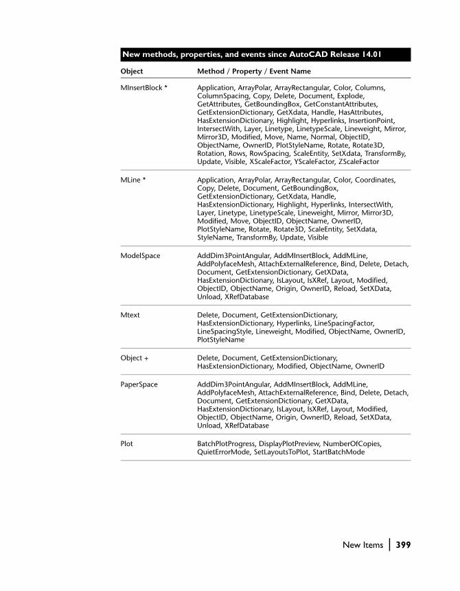
MInsertBlock * Application, ArrayPolar, ArrayRectangular, Color, Columns, ColumnSpacing, Copy, Delete, Document, Explode, GetAttributes, GetBoundingBox, GetConstantAttributes, GetExtensionDictionary, GetXdata, Handle, HasAttributes, HasExtensionDictionary, Highlight, Hyperlinks, InsertionPoint, IntersectWith, Layer, Linetype, LinetypeScale, Lineweight, Mirror, Mirror3D, Modified, Move, Name, Normal, ObjectID, ObjectName, OwnerID, PlotStyleName, Rotate, Rotate3D, Rotation, Rows, RowSpacing, ScaleEntity, SetXdata, TransformBy, Update, Visible, XScaleFactor, YScaleFactor, ZScaleFactor
MLine * Application, ArrayPolar, ArrayRectangular, Color, Coordinates, Copy, Delete, Document, GetBoundingBox, GetExtensionDictionary, GetXdata, Handle, HasExtensionDictionary, Highlight, Hyperlinks, IntersectWith, Layer, Linetype, LinetypeScale, Lineweight, Mirror, Mirror3D, Modified, Move, ObjectID, ObjectName, OwnerID, PlotStyleName, Rotate, Rotate3D, ScaleEntity, SetXdata, StyleName, TransformBy, Update, Visible
ModelSpace AddDim3PointAngular, AddMInsertBlock, AddMLine, AddPolyfaceMesh, AttachExternalReference, Bind, Delete, Detach, Document, GetExtensionDictionary, GetXData, HasExtensionDictionary, IsLayout, IsXRef, Layout, Modified, ObjectID, ObjectName, Origin, OwnerID, Reload, SetXData, Unload, XRefDatabase
Mtext Delete, Document, GetExtensionDictionary, HasExtensionDictionary, Hyperlinks, LineSpacingFactor, LineSpacingStyle, Lineweight, Modified, ObjectName, OwnerID, PlotStyleName
Object + Delete, Document, GetExtensionDictionary, HasExtensionDictionary, Modified, ObjectName, OwnerID
PaperSpace AddDim3PointAngular, AddMInsertBlock, AddMLine, AddPolyfaceMesh, AttachExternalReference, Bind, Delete, Detach, Document, GetExtensionDictionary, GetXData, HasExtensionDictionary, IsLayout, IsXRef, Layout, Modified, ObjectID, ObjectName, Origin, OwnerID, Reload, SetXData, Unload, XRefDatabase
Plot BatchPlotProgress, DisplayPlotPreview, NumberOfCopies, QuietErrorMode, SetLayoutsToPlot, StartBatchMode
New methods, properties, and events since AutoCAD Release 14.01
Object Method / Property / Event Name
New Items | 399

PlotConfiguration * Application, CanonicalMediaName, CenterPlot, ConfigName, CopyFrom, Delete, Document, GetCanonicalMediaNames, GetCustomScale, GetExtensionDictionary, GetLocaleMediaName, GetPaperMargins, GetPaperSize, GetPlotDeviceNames, GetPlotStyleTableNames, GetWindowToPlot, GetXdata, Handle, HasExtensionDictionary, ModelType, Modified, Name, ObjectID, ObjectName, OwnerID, PaperUnits, PlotHidden, PlotOrigin, PlotRotation, PlotType, PlotViewportBorders, PlotViewportsFirst, PlotWithLineweights, PlotWithPlotStyles, RefreshPlotDeviceInfo, ScaleLineweights, SetCustomScale, SetWindowToPlot, SetXdata, ShowPlotStyles, StandardScale, StyleSheet, UseStandardScale, ViewToPlot
PlotConfigurations * Add, Application, Count, Delete, Document, GetExtensionDictionary, GetXdata, Handle, HasExtensionDictionary, Item, Modified, ObjectID, ObjectName, OwnerID, SetXdata
Point Delete, Document, GetExtensionDictionary, HasExtensionDictionary, Hyperlinks, Lineweight, Modified, ObjectName, OwnerID, PlotStyleName
PolyfaceMesh * Application, ArrayPolar, ArrayRectangular, Color, Coordinate, Coordinates, Copy, Delete, Document, GetBoundingBox, GetExtensionDictionary, GetXdata, Handle, HasExtensionDictionary, Highlight, Hyperlinks, IntersectWith, Layer, Linetype, LinetypeScale, Lineweight, Mirror, Mirror3D, Modified, Move, NumberOfFaces, NumberOfVertices, ObjectID, ObjectName, OwnerID, PlotStyleName, Rotate, Rotate3D, ScaleEntity, SetXdata, TransformBy, Update, Visible
Polygonmesh Coordinate, Delete, Document, GetExtensionDictionary, HasExtensionDictionary, Hyperlinks, Lineweight, Modified, ObjectName, OwnerID, PlotStyleName
Polyline ConstantWidth, Coordinate, Delete, Document, Elevation, GetExtensionDictionary, HasExtensionDictionary, Hyperlinks, LinetypeGeneration, Lineweight, Modified, ObjectName, OwnerID, PlotStyleName
PopupMenu * AddMenuItem, AddSeparator, AddSubMenu, Application, Count, InsertInMenuBar, Item, Name, NameNoMnemonic, OnMenuBar, Parent, RemoveFromMenuBar, ShortcutMenu, TagString
PopupMenuItem * Application, Caption, Check, Delete, Enable, HelpString, Index, Label, Macro, Parent, SubMenu, TagString, Type
PopupMenus * Add, Application, Count, InsertMenuInMenuBar, Item, Parent, RemoveMenuFromMenuBar
New methods, properties, and events since AutoCAD Release 14.01
Object Method / Property / Event Name
400 | Appendix B Migrating from AutoCAD Release 14.01

Preferences Display, Drafting, Files, OpenSave, Output, Profiles, Selection, System, User
PreferencesDisplay * Application, AutoTrackingVecColor, CursorSize, DisplayLayoutTabs, DisplayScreenMenu, DisplayScrollBars, DockedVisibleLines, GraphicsWinLayoutBackgrndColor, GraphicsWinModelBackgrndColor, HistoryLines, ImageFrameHighlight, LayoutCreateViewport, LayoutCrosshairColor, LayoutDisplayMargins, LayoutDisplayPaper, LayoutDisplayPaperShadow, LayoutShowPlotSetup, MaxAutoCADWindow, ModelCrosshairColor, ShowRasterImage, TextFont, TextFontSize, TextFontStyle, TextWinBackgrndColor, TextWinTextColor, TrueColorImages, XRefFadeIntensity
PreferencesDrafting * AlignmentPointAcquisition, Application, AutoSnapAperture, AutoSnapApertureSize, AutoSnapMagnet, AutoSnapMarker, AutoSnapMarkerColor, AutoSnapMarkerSize, AutoSnapTooltip, AutoTrackTooltip, FullScreenTrackingVector, PolarTrackingVector
PreferencesFiles * AltFontFile, AltTabletMenuFile, Application, AutoSavePath, ConfigFile, CustomDictionary, DefaultInternetURL, DriversPath, FontFileMap, GetProjectFilePath, HelpFilePath, LicenseServer, LogFilePath, MainDictionary, MenuFile, ObjectARXPath, PostScriptPrologFile, PrinterConfigPath, PrinterDescPath, PrinterStyleSheetPath, PrintFile, PrintSpoolerPath, PrintSpoolExecutable, SetProjectFilePath, SupportPath, TempFIlePath, TemplateDwgPath, TempXrefPath, TextEditor, TextureMapPath, WorkspacePath
PreferencesOpenSave * Application, AutoAudit, AutoSaveInterval, CreateBackup, DemandLoadArxApp, FullCrcValidation, IncrementalSavePercent, LogFileOn, MRUNumber, ProxyImage, SaveAsType, SavePreviewThumbnail, ShowProxyDialogBox, TempFileExtension, XrefDemandLoad
PreferencesOutput * Application, DefaultOutputDevice, DefaultPlotStyleForLayer, DefaultPlotStyleForObjects, DefaultPlotStyleTable, OLEQuality, PlotLegacy, PlotPolicy, PrinterPaperSizeAlert, PrinterSpoolAlert, UseLastPlotSettings
PreferencesProfiles * ActiveProfile, Application, CopyProfile, DeleteProfile, ExportProfile, GetAllProfileNames, ImportProfile, RenameProfile, ResetProfile
PreferencesSelection * Application, DisplayGrips, DisplayGripsWithinBlocks, GripColorSelected, GripColorUnselected, GripSize, PickAdd, PickAuto, PickBoxSize, PickDrag, PickFirst, PickGroup
New methods, properties, and events since AutoCAD Release 14.01
Object Method / Property / Event Name
New Items | 401
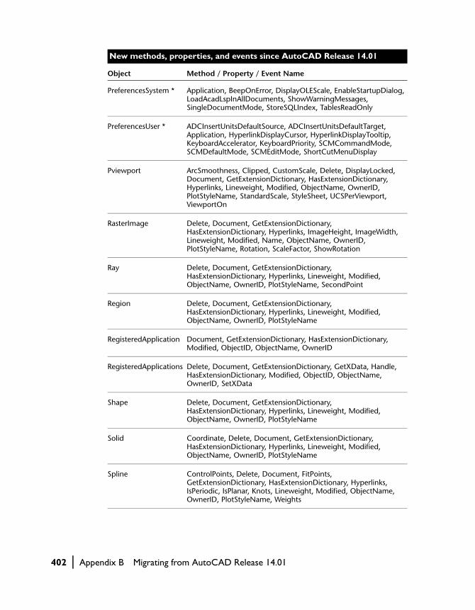
PreferencesSystem * Application, BeepOnError, DisplayOLEScale, EnableStartupDialog, LoadAcadLspInAllDocuments, ShowWarningMessages, SingleDocumentMode, StoreSQLIndex, TablesReadOnly
PreferencesUser * ADCInsertUnitsDefaultSource, ADCInsertUnitsDefaultTarget, Application, HyperlinkDisplayCursor, HyperlinkDisplayTooltip, KeyboardAccelerator, KeyboardPriority, SCMCommandMode, SCMDefaultMode, SCMEditMode, ShortCutMenuDisplay
Pviewport ArcSmoothness, Clipped, CustomScale, Delete, DisplayLocked, Document, GetExtensionDictionary, HasExtensionDictionary, Hyperlinks, Lineweight, Modified, ObjectName, OwnerID, PlotStyleName, StandardScale, StyleSheet, UCSPerViewport, ViewportOn
RasterImage Delete, Document, GetExtensionDictionary, HasExtensionDictionary, Hyperlinks, ImageHeight, ImageWidth, Lineweight, Modified, Name, ObjectName, OwnerID, PlotStyleName, Rotation, ScaleFactor, ShowRotation
Ray Delete, Document, GetExtensionDictionary, HasExtensionDictionary, Hyperlinks, Lineweight, Modified, ObjectName, OwnerID, PlotStyleName, SecondPoint
Region Delete, Document, GetExtensionDictionary, HasExtensionDictionary, Hyperlinks, Lineweight, Modified, ObjectName, OwnerID, PlotStyleName
RegisteredApplication Document, GetExtensionDictionary, HasExtensionDictionary, Modified, ObjectID, ObjectName, OwnerID
RegisteredApplications Delete, Document, GetExtensionDictionary, GetXData, Handle, HasExtensionDictionary, Modified, ObjectID, ObjectName, OwnerID, SetXData
Shape Delete, Document, GetExtensionDictionary, HasExtensionDictionary, Hyperlinks, Lineweight, Modified, ObjectName, OwnerID, PlotStyleName
Solid Coordinate, Delete, Document, GetExtensionDictionary, HasExtensionDictionary, Hyperlinks, Lineweight, Modified, ObjectName, OwnerID, PlotStyleName
Spline ControlPoints, Delete, Document, FitPoints, GetExtensionDictionary, HasExtensionDictionary, Hyperlinks, IsPeriodic, IsPlanar, Knots, Lineweight, Modified, ObjectName, OwnerID, PlotStyleName, Weights
New methods, properties, and events since AutoCAD Release 14.01
Object Method / Property / Event Name
402 | Appendix B Migrating from AutoCAD Release 14.01

State * Application, IsQuiescent
Text Alignment, Backward, Delete, Document, GetExtensionDictionary, HasExtensionDictionary, Hyperlinks, Lineweight, Modified, ObjectName, OwnerID, PlotStyleName, UpsideDown
TextStyle Document, GetExtensionDictionary, GetFont, HasExtensionDictionary, Modified, ObjectID, ObjectName, OwnerID, SetFont
TextStyles Delete, Document, GetExtensionDictionary, GetXData, Handle, HasExtensionDictionary, Modified, ObjectID, ObjectName, OwnerID, SetXData
Tolerance Delete, DimensionLineColor, Document, GetExtensionDictionary, HasExtensionDictionary, Hyperlinks, Lineweight, Modified, ObjectName, OwnerID, PlotStyleName, ScaleFactor, TextColor, TextHeight, TextStyle
ToolBar * AddSeparator, AddToolbarButton, Application, Count, Delete, Dock, DockStatus, Float, FloatingRows, Height, HelpString, Item, LargeButtons, Left, Name, Parent, TagString, Top, Visible, Width
ToolbarItem * Application, AttachToolbarToFlyout, Delete, Flyout, GetBitmaps, HelpString, Index, Macro, Name, Parent, SetBitmaps, TagString, Type
Toolbars * Add, Application, Count, Item, LargeButtons, Parent
Trace Coordinate, Delete, Document, GetExtensionDictionary, HasExtensionDictionary, Hyperlinks, Lineweight, Modified, ObjectName, OwnerID, PlotStyleName
UCS Document, GetExtensionDictionary, HasExtensionDictionary, Modified, ObjectID, ObjectName, OwnerID
UCSs Delete, Document, GetExtensionDictionary, GetXData, Handle, HasExtensionDictionary, Modified, ObjectID, ObjectName, OwnerID, SetXData
Utility GetRemoteFile, GetSubEntity, IsRemoteFile, IsURL, LaunchBrowserDialog, Prompt, PutRemoteFile
View Document, GetExtensionDictionary, HasExtensionDictionary, Modified, ObjectID, ObjectName, OwnerID
New methods, properties, and events since AutoCAD Release 14.01
Object Method / Property / Event Name
New Items | 403
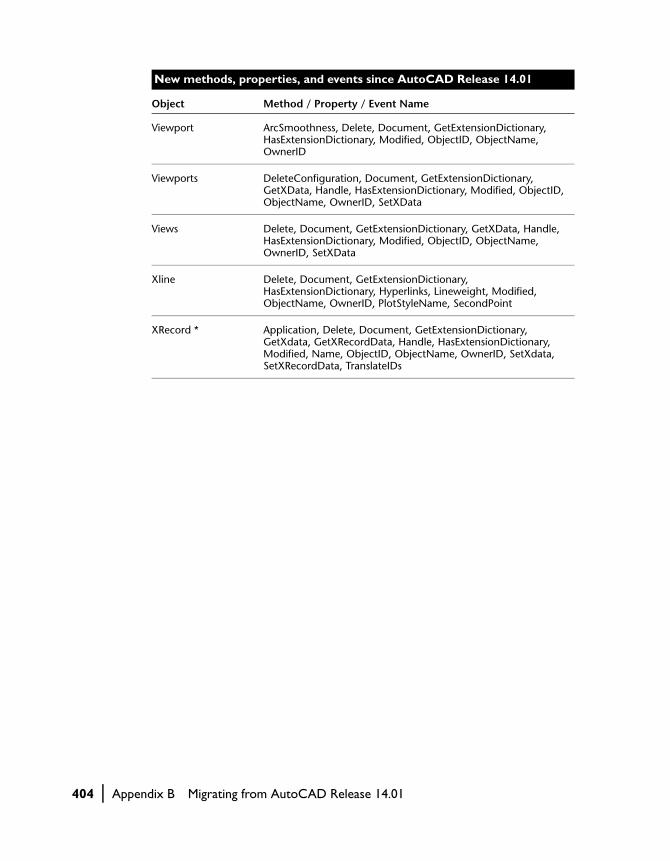
Viewport ArcSmoothness, Delete, Document, GetExtensionDictionary, HasExtensionDictionary, Modified, ObjectID, ObjectName, OwnerID
Viewports DeleteConfiguration, Document, GetExtensionDictionary, GetXData, Handle, HasExtensionDictionary, Modified, ObjectID, ObjectName, OwnerID, SetXData
Views Delete, Document, GetExtensionDictionary, GetXData, Handle, HasExtensionDictionary, Modified, ObjectID, ObjectName, OwnerID, SetXData
Xline Delete, Document, GetExtensionDictionary, HasExtensionDictionary, Hyperlinks, Lineweight, Modified, ObjectName, OwnerID, PlotStyleName, SecondPoint
XRecord * Application, Delete, Document, GetExtensionDictionary, GetXdata, GetXRecordData, Handle, HasExtensionDictionary, Modified, Name, ObjectID, ObjectName, OwnerID, SetXdata, SetXRecordData, TranslateIDs
New methods, properties, and events since AutoCAD Release 14.01
Object Method / Property / Event Name
404 | Appendix B Migrating from AutoCAD Release 14.01
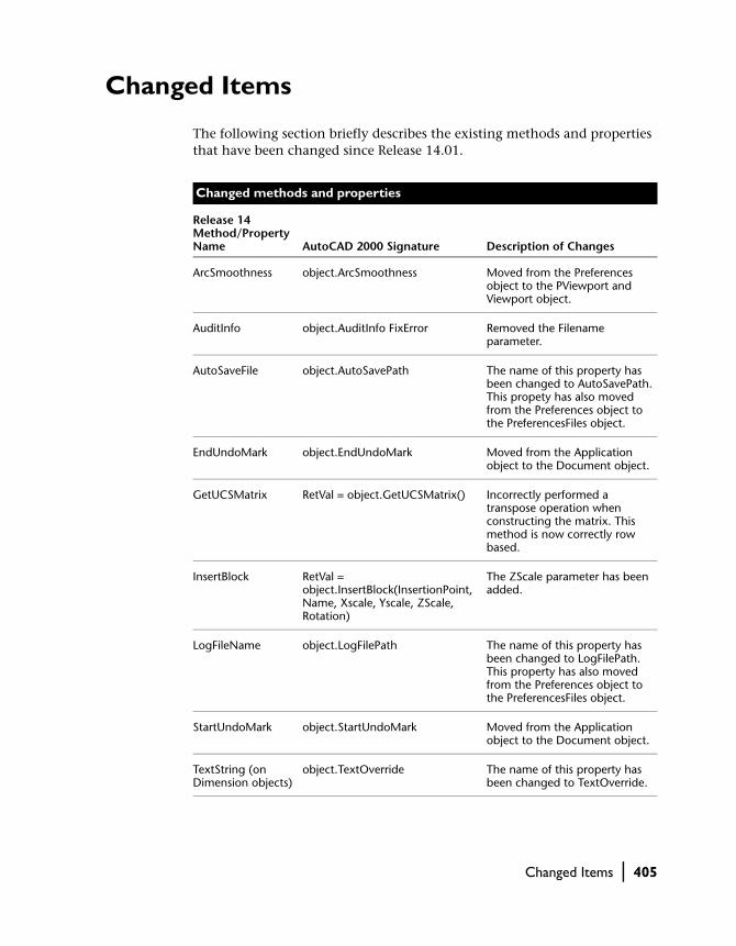
Changed Items
The following section briefly describes the existing methods and properties that have been changed since Release 14.01.
Changed methods and properties
Release 14 Method/Property Name AutoCAD 2000 Signature Description of Changes
ArcSmoothness object.ArcSmoothness Moved from the Preferences object to the PViewport and Viewport object.
AuditInfo object.AuditInfo FixError Removed the Filename parameter.
AutoSaveFile object.AutoSavePath The name of this property has been changed to AutoSavePath. This propety has also moved from the Preferences object to the PreferencesFiles object.
EndUndoMark object.EndUndoMark Moved from the Application object to the Document object.
GetUCSMatrix RetVal = object.GetUCSMatrix() Incorrectly performed a transpose operation when constructing the matrix. This method is now correctly row based.
InsertBlock RetVal = object.InsertBlock(InsertionPoint, Name, Xscale, Yscale, ZScale, Rotation)
The ZScale parameter has been added.
LogFileName object.LogFilePath The name of this property has been changed to LogFilePath. This property has also moved from the Preferences object to the PreferencesFiles object.
StartUndoMark object.StartUndoMark Moved from the Application object to the Document object.
TextString (on Dimension objects)
object.TextOverride The name of this property has been changed to TextOverride.
Changed Items | 405

TransformBy object.TransformBy TransformationMatrix
Incorrectly performed a transpose operation when constructing the matrix. This method is now correctly row based.
TranslateCoordinates RetVal = TranslateCoordinates(OriginalPoint, From, To, Disp[,OCSNormal])
Added the OCSNormal parameter as well as the acOCS option for the From and To parameter to allow coordinate translations to and from an OCS.
ZoomAll object.ZoomAll () This method has moved off the PViewport and Viewport objects to the Application object.
ZoomCenter object.ZoomCenter Center, Magnify
This method has moved off the PViewport and Viewport objects to the Application object.
ZoomExtents object.ZoomExtents This method has moved off the PViewport and Viewport objects to the Application object.
ZoomPickWindow object.ZoomPickWindow This method has moved off the PViewport and Viewport objects to the Application object.
ZoomScaled object.ZoomScaled Scale, ScaleType
This method has moved off the PViewport and Viewport objects to the Application object.
ZoomWindow object.ZoomWindow LowerLeft, UpperRight
This method has moved off the PViewport and Viewport objects to the Application object.
Changed methods and properties (continued)
Release 14 Method/Property Name AutoCAD 2000 Signature Description of Changes
406 | Appendix B Migrating from AutoCAD Release 14.01

Preferences Object
The Preferences object has several major changes:
■ The Preferences object has been subdivided extensively. The new objects that contain preferences are:PreferencesDisplayPreferencesDraftingPreferencesFilesPreferencesOpenSavePreferencesOutputPreferencesSelectionPreferencesSystemPreferencesUserDatabasePreferences
All properties and methods previously found on the Preferences object have been moved to one of the objects listed above. To find the new object for any given Preferences methods and properties, look up the method or property in the AutoCAD ActiveX and VBA Reference.
■ All properties specifying color have been changed to use the VB constant OLE_COLOR instead of the AutoCAD color constants. (Note that this applies only to properties found on the Preferences objects listed above.)
Changed Items | 407

Removed Items
The following section briefly describes the existing methods and properties that have been removed since AutoCAD Release 14.01.
Removed methods and properties
Release 14 Method/Property Name Migration Options
AdjustAreaFill Set in a PC3 configuration file (via the Plotter Configuration Editor).
CrosshairColor Use PreferencesDisplay.ModelSpaceCrosshairColor or PreferencesDisplay.LayoutCrosshairColor.
EntityName Use the AutoCAD ActiveX ObjectName property, or in VB and VBA use the TypeOf keyword or TypeName function.
EntityType See EntityName above.
Erase Removed from all objects except Selection Set. Use the Delete method instead of Erase.
GraphicsTextBack-grndColor
Graphics text uses the same background color as the graphics. Use PreferencesDisplay.GraphicsWinLayoutBackgrndColor and PreferencesDisplay.GraphicsWinModelBackgrndColor.
GraphicsTextColor Graphics text uses the same color as the pointer (crosshair). Use PreferencesDisplay.LayoutCrosshairColor and PreferencesDisplay.ModelCrosshairColor.
HideLines Use AcadLayout.Hidden.
ListADS EXE-based ADSRX apps are not supported in AutoCAD 2000. The method for querying ARX and DBX apps is ListARX.
LoadADS EXE-based ADSRX apps are not supported in AutoCAD 2000. The method for loading ARX and DBX apps is LoadARX.
LoadPC2 PC2 files are not supported in AutoCAD 2000. You will need to convert your PC2 files to PC3 files via the Add-a-Plotter Wizard.
MonochromeVec-tors
Obsolete functionality.
Origin Use AcadLayout.PlotOffset.
PaperSize Use AcadLayout.CanonicalMediaName.
408 | Appendix B Migrating from AutoCAD Release 14.01
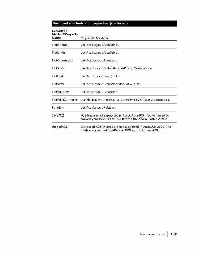
PlotExtents Use AcadLayout.AreaToPlot.
PlotLimits Use AcadLayout.AreaToPlot.
PlotOrientation Use AcadLayout.Rotation .
PlotScale Use AcadLayout.Scale, StandardScale, CustomScale.
PlotUnits Use AcadLayout.PaperUnits.
PlotView Use AcadLayout.AreaToPlot and ViewToPlot.
PlotWindow Use AcadLayout.AreaToPlot.
PlotWithConfigFile Use PlotToDevice instead, and specify a PC3 file as an argument.
Rotation Use AcadLayout.Rotation.
SavePC2 PC2 files are not supported in AutoCAD 2000. You will need to convert your PC2 files to PC3 files via the Add-a-Plotter Wizard.
UnloadADS EXE-based ADSRX apps are not supported in AutoCAD 2000. The method for unloading ARX and DBX apps is UnloadARX.
Removed methods and properties (continued)
Release 14 Method/Property Name Migration Options
Removed Items | 409

410

Index
Symbols\ (backslash),
format code, 171^ (caret)
stacked text indicator, 171# (pound sign)
stacked text indicator, 171/ (slash, forward)
stacked text indicator, 1712D objects
editing, 114positioning, 263
3D drawingscoordinates, 254right-hand rule, 254World Coordinate System (illustration), 254
3D modeling3DSolid object, 267Add 3DPoly method, 263AutoCAD Designer, 262in 3D space, 263meshes (illustration), 262mirroring (illustration), 271rectangular arrays (illustration), 269rotating (illustration), 268solids (illustration), 262solids, analyzing properties (list), 274solids, combining, 272solids, methods for creating (list), 267surface, 262wireframe (illustration), 261wireframes, creating, 263
3D polylinesconverting to regions, 107creating, 263
3DMesh object, example code, 2653DSolid object
defined, 267example code, 267, 268, 271
Aacad.dvb project file, 28ACADProject file, 30acAttributeModeConstant constant, 311acAttributeModeInvisible constant, 311acAttributeModeNormal constant, 311acAttributeModePreset constant, 311acAttributeModeVerify constant, 311acByBlock constant, 149acByLayer constant, 149accelerator keys, specifying for menus, 215acDisplay, 278acExtents, 278ACI number, layers, 149acIntersection constant, 110acLayout, 278acLimits, 278acSubstraction constant, 110Activate event, 245Active UCS property, 84ActiveDimStyle property, 190ActiveLayer property, example code, 146ActiveLinetype property, 152ActivePViewport property, example code, 283ActiveSpace property
example code, 281view changing, 279, 280
ActiveTextStyle property, 84ActiveUCS property, User Coordinate
System, 258ActiveViewport property
current viewport, 82example code, 84resetting objects, 84
ActiveViewport property, example code, 265ActiveX interface
advantages with AutoCAD, 16and AutoCAD objects, 18and VBA applications, 18types of objects, 16
acUnion constant, 110acView, 278
411

acWindow, 278Add method
blocks, example code, 307collections, 52, 57dimension styles, 190Documents collection, 68example code, 68Layers collection, 145layers, example code, 115, 146leader lines, 199menu groups, example code, 208menus, example code, 212selection sets, example code, 116text styles, 158toolbars, example code, 221UCS, example code, 258User Coordinate System, 257
Add3DMesh methodexample code, 265MClose property, 264NClose property, 264
Add3DPoly method, 3D modeling, 263AddArc method, 104AddAttribute method
defining blocks, 310AddBox method
creating solids, 267example code, 268, 271, 272
AddCircle methodcreating circles, 104example code, 108, 109
AddCone method, 267AddCylinder method
creating solids, 267example code, 272
AddDim3PointAligned method, 183AddDimAligned method
example code, 189, 196linear dimensions, 183
AddDimAngular methodangular dimensions, 186example code, 186
AddDimDiametric method, 185AddDimOrdinate method
example code, 188ordinate dimensions, 187
AddDimRadial method, 185example code, 185radial dimensions, 184
AddDimRotated method, 183, 184AddEllipse method, 104AddEllipticalCone method, 267AddEllipticalCylinder method, 267AddExtrudedSolid method, 267AddExtrudedSolidAlongPath method, 267AddFitPoint method, splines, 139
AddHatch methodcreating objects, 111example code, 113, 141, 143
AddItem method, 116AddLeader method
creating leader lines, 198example code, 198, 199
AddLightweightPolyline methodexample code, 103, 122Garden Path tutorial, 359
AddLine methodexample code, 132, 134object hierarchy, 54
AddMenuItem method, 212, 213Count property, 212example code, 208
AddMInsertBlock method, 306AddMText method
example code, 170, 172, 199multiline text, 169
AddPoint method, example code, 106AddPolyfaceMesh method
creating meshes, 265example code, 266
AddPViewport methodexample code, 283paper space, 282
AddRaster methodattaching images, 296example code, 297, 302
AddRegion method, 108calculating total number of regions, 108example code, 108, 109
AddRevolvedSolid method, 267AddSeparator method, using Type property, 214AddSolid method
creating solids, 267example code, 107solid-filled area, 106
AddSphere method, 267AddSpline method
example code, 104, 140NURBS, 104
AddSubMenu method, example code, 216AddText method, example code, 165AddText method, example code, 162–163AddTolerance method
example code, 202geometric tolerance, 201
AddToolbarButton method, 221creating flyout toolbars, 225example code, 223, 225
AddTorus method, 267AddVertex property, polylines, 137AddWedge method
creating solids, 267example code, 267
412 | Index

AddXLine method, in 3D, 88AddXLine object, example code, 88Alignment property, 166, 313
example code, 167in text, 166
AltFontFile property, 176AngleFromXAxis method, 91, 357AngleToReal method, 91AngleToString method, 91angular dimensions
(illustration), 180creating, 186
annotations, and leader lines, 197AppActivate event, 242AppDeactivate event, 242AppendInnerLoop method
boundaries, 112example code, 141hatches, 141
AppendOuterLoop methodboundaries, 112example code, 113, 141, 143hatches, 141
application level eventsclass modules, 243declaring objects with events, 243enabling, 242, 243events (list), 242
Application objectcollections, accessing, 57declaring objects with events, 243events (list), 242example code, 244, 345root object, accessing, 50
Application windowchanging visibility, 50finding state, 71finding status, example code, 72modifying, 50modifying position, 71sizing, 71Visible property, 72WindowState property, 72
applicationsdeclaring Windows APIs, 349distribution options, 340exchanging data with AutoCAD, 342instances, creating, 344object model referencing, 342quit methods, 345referencing application objects, 344variables, declaring, 344
Arc object, creating, 104Area property, 110
calculating for closed objects, 91calculating for open objects, 92example code, 93, 109
Area property (continued)splines, 140
array data, converting to variants, 61arraying, patterns, 119ArrayPolar method
attributes, 313creating arrays, 124dimension editing, 189Text object, 168
ArrayRectangular method, 125, 269attributes, 313dimension editing, 189Text object, 168
arrayspolar, 124rectangular, 124, 125
ARXLoaded event, 242ARXUnloaded event, 242associative dimensions, defined, 183AssociativeHatch property, 141AttachExternalReference method
example code, 318, 320, 321AttachmentPoint property, 174AttachToolbarToFlyout method,
example code, 225Attribute object
editing, 313example code, 315
attributesassociating, 310in blocks (illustration), 310constants (list), 311creating references, 310and definitions, 315editing methods (list), 313editing properties (list), 313extracting, 310and references, 315for text, 310visibility, 310
Auto Data Tips, Code window, 42auto embedding, setting for VBA projects, 33Auto Indent, Code window, 42Auto List Member, Code window, 42Auto Quick Info, Code window, 42Auto Syntax Check, Code window, 42AutoCAD
exchanging data, 342reinstalling, 19
AutoCAD Designer, 262AutoCAD VBA, system requirements, 19
Bbackslash (\)
format code, 171backslash character, in macros, 233
Index | 413

Backward propertyattributes, 313
base point, rotating objects, 128BasePoint property, 89BatchPlotProgress property, 289BeginClose event, 245BeginCommand event, 240, 242, 245BeginDoubleClick event, 245BeginFileDrop event
defined, 242example code, 244
BeginLISP event, 242, 245BeginModal event, 242BeginOpen event, 240, 242BeginPlot event, 242, 246BeginQuit event, 242BeginRightClick event, 246BeginSave event, 242, 246BeginShortcutMenuCommand event, 246BeginShortcutMenuDefault event
defined, 246example code, 249
BeginShortcutMenuEdit event, 246BeginShortcutMenuGrip event, 246BeginShortcutMenuOsnap event, 246Big Font files, 161BigFontFile property
example code, 161TextStyle object, 159
Bind methodexample code, 323external references, 322
bitonal imagesSee raster images
BLIPMODE system variable, 363Block object
example code, 307in layouts, 276
Block property, in layouts, 277block references
and arrays, 306base points, 306exploding, 303, 307fastener (illustration), 306iteration, 306listing attributes, 345naming, 306redefining, 305
BlockReference objectexample code, 307, 315, 345leader lines, 199
blocksattributes, 310binding, 322color properties, 151creating new blocks, 305creating objects, 102
blocks (continued)defined, 303exploding, 134inserting, 305inserting (illustration), 303and layers, 149, 154and layers (illustration), 304linetype properties, 152nesting, 304nesting (illustration), 305and object properties, 304organizing objects, 303redefining, 308referencing in ActiveX code, 102uses of (list), 303
BMP filesexporting to, 99importing, 99
Boolean intersection (illustration), 272Boolean method, 272
calculating area, 91composite regions, 109creating regions, 109example code, 109
boundaries, Hatch object, 111Boundary Hatch dialog box, pattern option, 142boxes
adding, example code, 268, 272mirroring, example code, 271slicing, example code, 274
Break mode, defined in VBA, 34break on errors, for VBA projects, 33Brightness property, 300
Ccalculations
AddRegion method, 108performing in drawings, 85
CanonicalMedia-Name property, 277caret (^)
stacked text indicator, 171cascading menus, See submenusCELTSCALE system variable, 154Center property
example code, 284WCS coordinate, 58
character formatting, example code, 172characters, adjusting spaces between, 171CheckInterference method, 272
example code, 272child object, relation to root object, 59Circle object, 58
creating, 104example code, 108, 109, 120
circular references, defined, 41Clear method, in selection sets, 119
414 | Index

ClipBoundary method, 301example code, 302
ClippingEnabled property, 299, 301example code, 302
Close methodDocuments collection, 68
Closed propertypolylines, 137splines, 139
CMDECHO system variable, 363Code window
in Garden Path tutorial, 353margin indicator bar, 38Object Box, 355Procedure/Event Box, 355resizing, 38settings, 42split bar, 38
collectionsadding members, 52Application object, accessing, 57available in AutoCAD (list), 55Count Property, 52defined, 55Document object, accessing, 56Documents, 50Item method, 52MenuBar, 204MenuGroup, 204as object groups, 52
layers, and color, 144Color property
changing linetypes, 155example code, 117layers, 149, 151raster images, 299
colors, assigning to objects, 154command line
controlling user input, 96in zero document state, 339prompting user, 94
compile timeerrors in VBA, 334object referencing, 59
ConfigName property, 279, 290confirguation, transformation matrix
(table), 130construction lines
(illustration), 88modifying, 87rays, 87xlines, 87
ContourlinesPerSurface property, 274Contrast property, 300control codes, text formatting (table), 175control points, in splines, 138
ControlPoints property, splines, 139controls for forms
adding code, 331adding to forms, 330control toolbox, 330for formatting in VBA, 330modifying, 330
conversion functionsoperation methods, 53
converting coordinatesTranslateCoordinates method, 259
coordinates, converting between systems, 259Coordinates property, polylines, 137Copy method, 119, 168, 189, 313copying
arraying, 119mirroring, 119multiple objects, 120offsetting, 119single object, 119
CopyObjects method, 120example code, 120
Count property, 52for menus, 212
CreateObject method, 64CreatePoint object,
example code, 106CreateRegion,
example code, 108CreateSolid object,
example code, 107CreateSpline,
example code, 104CreateTypedArray method, 61, 91creating lines
Add Polyline, 103AddLightweightPolyline method, 103AddLine method, 103AddMLine method, 103
creating objectsdefault linetype, 156graphical, 52in blocks, 102in model space, 102in paper space, 102nongraphical, 52
crosshairs, resizing, 70cursor
restricting with Ortho mode, 86restricting with Snap mode, 85
cursor menusadding new items, 236creating, 211deleting, 211on graphics screen, 211Shortcut menu property, 236truncating, 211
Index | 415

CursorSize propertycrosshairs, resizing, 70
curved objectsarcs, 103circles, 103ellipses, 103spline curves, 103
CustomDictionary property, 177cylinder
adding, example code, 272
DDAO
object library, 348See also data access objects
data access objectsand databasesin VBA environment, 347
DatabasePreferences objectstoring options, 70
DCSconverting coordinates, 260definition, 260
DDIM Annotation dialog box, 190DDIM Format dialog box, 190DDIM Geometry dialog box, 190Deactivate event, 246Declare statement, requirements (list), 349default, VBA project name, 30Default to Full Module View
Project window, 42Degree property, splines, 140degrees, converting from radians, 353Delete method, 79
collections, 129deleting views, example code, 79example code, 217in selection sets, 119layers, 150linetypes, 153
DeleteFitPoint methodsplines, 139
deletingcollection member, 58macros, from Macros dialog box, 33
demand loadingand indexes, 324performance benefits, 324
Description propertyexample code, 153linetypes, 153
design mode, VBA environment, 329Detach method
example code, 320external references, 319
dialog boxesin modal forms, 333
dialog boxes (continued)macro, 31options for VBA IDE, 42Save Project, 40VBA Manager, 27
dialog controls See controls
DIESEL string expressions, 213DimAligned object
example code, 189, 196DimAngular object
example code, 186DIMASO system variable, 183DIMCLRD system variable, 202DIMCLRT system variable, 200, 202dimension lines (illustration), 181dimension styles
active, 183Add method, 190creating dimensions, 190modifying, 190parent, 190
dimension styles (illustration), 190dimension system variables, (list), 181, 184dimensions
and geometry, 197angular, 180angular (illustration), 186annotations, 182associative, 183hook lines (illustration), 185, 198in model space, 197in paper space, 197leader line (illustration), 182leader lines (illustration), 197LeaderLength setting, 186linear, 180methods, editing, 188modifying, 183ordinate (illustration), 187properties, editing, 188radial, 180radial, creating, 184rotating, 184text styles, 182text styles (illustration), 182types of (illustration), 180
DIMFIT system variable, 184DIMGAP system variable, 202DIMJUST system variable, 181, 184DIMLFAC system variable, 197DimOrdinate object
example code, 188DimRadial object
example code, 185DIMTAD system variable, 181, 184DIMTIH system variable, 181, 184
416 | Index

DIMTOFL system variable, 181, 184DIMTOH system variable, 181, 184DIMTXSTY system variable, 200DIMTXT system variable, 200, 202DIMTXTSTY system variable, 202DIMUPT system variable, 181, 184Direction property, 282
example code, 265, 283DirectionVector property, 89
example code, 89displacement vector
Move method, 127Display Coordinate System, definition, 260Display method
in viewports, 281Display preference
Options dialog box, 69Display property
example code, 282, 283displaying macros, from Macros dialog box, 31DisplayPlotPreview method, 289DisplayScreenMenu property, 70DisplayScrollBar property, 70DistanceToReal method, 91distributing applications
VB, 340VBA, 340
Dock methoddocking toolbars, 226example code, 227
document level eventsand Document object, 248coding, 249declaring objects with events, 247enabling, 245events (list), 245right-clicking, 245
Document objectActiveViewport property, 82as AutoCAD drawing, 50declaring objects with events, 247enabling events, 245events (list), 245example code, 249, 281, 283model space, accessing, 50modifying drawings, 68paper space, accessing, 50ZoomAll method, 78ZoomExtents method, 78
Document windowcreating views, 79Delete method, 79displaying views, 73maximizing, 73minimizing, 73modifying position, 73Regen method, 83
Document window (continued)sizing, 73Split method, 81status of active document, 74Update method, 83viewports, 80viewports, splitting, 81WindowState property, 73Zoom option, 74zoom scale, specifying, 76ZoomAll method, 78ZoomCenter method, 77ZoomExtents method, 78ZoomPickWindow, 75ZoomWindow, 75
Documents collection, links to drawing, 50Drafting preference
Options dialog box, 69Drag and Drop Text Editing
Project window, 42drawing display, defined, 48drawing extents
and rays, 89zooming to, 77
drawingsperforming calculations, 85text styles, 157See 3D drawings
drawing-stored options, setting, 70dtr function, in Garden Path tutorial, 353DWF files, exporting to, 99DXF codes, and filter types (table), 117DXF files
exporting to, 99importing, 99
DXF group codesfilter types, specifying, 117
Eediting
2D objects, 114nongraphical objects, 114polylines, 136
editing macros, from Macros dialog box, 32ElevateOrder method
splines, 139Ellipse object, creating, 104embedded projects
auto embed feature, 34ThisDrawing object, 54
enablingapplication level events, 243
EndAngle property, 134EndCommand event, 240, 242, 246EndLISP event, 242, 246EndModal event, 242EndOpen event, 240, 243
Index | 417

EndPlot event, 243, 247EndPoint property, 134
example code, 134EndSave event, 243, 247EndShortcutMenu event, 247EndTangent property
splines, 139EntShortcutMenu event
example code, 249EPS files, exporting to, 99ERASE command, macros, 235Erase method, 122, 168, 189, 313
in selection sets, 119leader lines, 199
Err object, properties of (list), 336errors
at runtime, 334Break mode, 34at compile time, 334Err object, 336error messages, 334error trapping, 334ignoring errors, 335user input control, 337
Evaluate method, 113example code, 113, 141in hatches, 141leader lines, 200
event handlersand infinite loops, 241and interactive functions, 241and parameters, 240and subroutines, 240Begin events, 240creating objects, 241deleting objects, 241End events, 240writing guidelines, 240
eventsdocument level, coding, 249enabling application level events, 243enabling object level events, 250handling document level events, 245InitializeEvents procedure, 248
events in AutoCAD, 240Excel
extracting attributes, example code, 345Explode method, 135, 307
example code, 307exploding
blocks, 134objects, 134polylines, 134
Export method, 99extended data
uses of, 52with graphical objects, 52
external referencesattaching, 317binding, 322defined, 317demand loading, 324detaching, 319and indexes, 324overlaying, 319reloading, 321unloading, 322updating, 317
ExternalReference objectexample code, 318, 320, 321, 322, 323
Fface meshes, converting to regions, 107Fade property, 300FieldLength property, 313Files preference
Options dialog box, 69FILLMODE system variable, 106filter lists, 117
example code, 118filter types, and DXF codes (table), 117filtering
example code, 118selection sets, 117
fit pointsin splines (illustration), 138modifying in splines, 138
FitPoints propertysplines, 139
FitTolerance propertysplines, 139
Float methodfloating toolbars, 226
floating viewportslayers, 144See also viewports
flyout buttonnew ToolbarItem object, 222
Flyout propertyToolbarItem object, 229
flyout toolbarsAddToolbarButton method, 225example code, 225
FontFile property, 159, 160, 161example code, 161
FontFileMap property, 176fonts
alternative, specifying, 176and text styles, 176assigning in drawings, 159Big Font files, 161in drawings (illustration), 159exporting in drawings, 160font mapping tables, 176
418 | Index

fonts (continued)SHX fonts, 160, 176specifying, 171substituting, 176substitution rules (table), 177TEXTFILL system variable, 160transforming in drawings, 160TrueType, 160Unicode, 161
form controls See controls
Format menu, VBA IDE, 330formatting characters
example code, 172MText object, 170
formsadding controls, 330control toolbox, 330displaying, 332formatting controls in VBA, 330hiding, 332hiding in Garden Path tutorial, 374importing into VBA, 37loading at runtime, 332as macros, 332modal dialog boxes, 333modal, defined, 332modifying controls, 330unloading, 332VBA environment, 329VBA project component, 36visibility at runtime, 331
Freeze property, 148
GGarden Path tutorial
adding code, 372adding dialog boxes, 365AddLightweightPolyline method, 359Code window (illustration), 373creating dialog boxes (illustration), 366creating new macro, 352declaring variables, 355determining corners, 359determining values, 374dtr function, 353entering code, 353event handling, 373GetDistance method, 357GetPoint method, 357gpuser subroutine, 356hiding forms, 374installing VBA environment, 352locating rows, 361macro control, 363option controls, 372pangle variable, 357
Garden Path tutorial (continued)PolarPoint method, 359prompt sequence, 352running macros, 364saving files, 354setting parameters, 357stepping through code, 363text edit box, 373ThisDrawing object, 357updating code, 369using prompts, 353Utility object, 354
geometric tolerancescreating, 201modifying, 201
GetAttributes method, 315example code, 315, 345
GetBitmaps method, 223example code, 224
GetDistance method, 91example code, 91Garden Path tutorial, 357
GetFitPoint methodsplines, 139
GetFont methodexample code, 160
GetKeyword method, 96example code, 95
GetObject method, 64GetObject, VBA function
example code, 244GetPoint method, 96, 363
defined, 95example code, 95, 258Garden Path tutorial, 357
GetString method, 96example code, 94
GetUCSMatrix method, 257GetVariable method, 85GetXData method
example code, 326global projects
defined, 26ThisDrawing object, 54
graphical objectsdefined, 48editing commands, 52properties, 52visible objects, 52
GridOn property, 282
HHatch object
AppendInnerLoop method, 112AppendOuterLoop method, 112AssociativeHatch property, 141associativity, 111, 141
Index | 419

Hatch object (continued)boundaries, 112Boundary Hatch dialog box, 142creating, 111editing, 141, 143example code, 113, 141, 143handling islands, 112patterns, 111, 142patterns (illustration), 142specifying loops, 111
hatches, editing, 141HatchStyle property
definitions (table), 112handling islands, 112
Height property, 159, 162, 299, 313example code, 162, 284
help, status line, for menus and toolbars, 235HelpString property
ToolbarItem object, 222, 228hierarchy
accessing objects in VBA, 54referencing objects, 54
hook lines (illustration), 198
Iimage boundaries, defined, 298ImageFile property, 297ImageHeight property, 299images
See raster imagesImageVisibility property, 300ImageWidth property, 299Import method
file conversions, 99importing
forms, 37modules, 37
Index propertyToolbarItem object, 228
INDEXCTL system variable, 324indexes
and demand loading, 324and external references, 324
InitializeUserInputexample code, 96
InitializeUserInput method, 94, 337(list), 96defining keywords, 96
INSBASE system variable, 306InsertBlock method, 305
example code, 307InsertInMenuBar method, 206
example code, 210, 214–216, 220, 235from PopupMenu object, 208
InsertionPoint property, 166, 313InsertLoopAt method, 141
InsertMenuInMenuBar method, 206example code, 208from PopupMenus collection, 208
intersecting regionsRegion object, 110
IsPeriodic propertysplines, 140
IsPlanar propertysplines, 140
IsRational propertysplines, 140
Item method, 52iterating collections, 57
iterating collectionsexample code, 145
Jjustification, format codes, 172
Kkeywords
command line, 96user input keywords, 96
Knots propertysplines, 139
LLabel property
accelerator key, 214Labels for menus
captions, 213special codes, 213
LAYER commandmacros, 233
Layer objectexample code, 115, 146, 147
Layer property, 155, 282raster images, 299
LayerOn property, 147example code, 147
layers(illustration), 144ACI number, 149, 150ActiveLayer property, 146assigning linetypes, 149assigning properties, 145assigning to objects, 154and blocks, 149changing layers, 155Color property, 149color, assigning, 149, 150default layer, 145freezing, 147, 148locking, 148naming, 145new object properties, 151
420 | Index

layers (continued)plotting, 147setting color, 155standard colors (table), 150turning off (illustration), 147
Layers collection, 145example code, 145
Layout object, 276example code, 290
layoutsBlock object, 276Block property, 276CanonicalMedia-Name property, 277Layout object, 276lineweight scale, 278in model space, 276paper size, 277in paper space, 276PaperUnits property, 277plot elements, 277PlotConfiguration object, 277plotting input values (list), 278switching model space and
paper space, 281LayoutSwitched event, 247leader lines
(illustration), 197annotations, 199associativity and editing, 200associativity with annotations, 199color, 197creating, 197determining type, 198modifying, 197scale, 197scaling, 200updating geometry, 200
Leader objectexample code, 198, 199
LensLength property, 282LightweightPolyline object, 137
creating, 103example code, 103, 122, 123
LIN library files, and linetypes, 151Line object
creating, 103example code, 132, 134
linear dimensions(illustration), 180aligning, 184creating, 183modifying properties
(illustration), 183, 184rotating, 184
linescreating, 103lengthening, 134
lines (continued)Ray object, 87Xline object, 87
Linetype objectexample code, 152, 153
Linetype property, 150, 282defining for layers, 156example code, 156raster images, 299
layers, and linetypes, 144linetypes
active, 152assigning to layers, 149assigning to objects, 154changing descriptions, 153changing linetype object, 156complex, 151continuous (illustration), 156default linetype, 156deleting, 153examples of (illustration), 151LIN library files, 151Load method, 151new object properties, 152renaming, 152scales (illustration), 153x-ref dependent, 152
Linetypes collection, 145LinetypeScale property, 154, 282lineweights, scaling in layouts, 278LISPCancelled event, 243, 247listing, ObjectARX applications, 50Load method
example code, 152, 207linetypes, 151, 157MenuGroups collection, 206
loadingObjectARX applications, 50VBA projects on startup, 338projects in AutoCAD, 27projects in VBA, 41
Lock property, 149loops, defining regions, 107LowerLeftCorner property
(illustration), 82LTSCALE system variable, 154
Mmacro libraries, referencing, 41Macro property, 213, 337
ToolbarItem object, 222, 228macros
and projects, 26backslash character, 233canceling commands, 234command handling, 234creating in tutorial, 352
Index | 421

macros (continued)delays (list), 233deleting, 33displaying, 31editing, 32enabling virus protection, 34ERASE command, 235guidelines for writing, 229in menus, 229in toolbars, 229in VBA, 34LAYER command, 233naming, 33object selection, single, 235running, 32running from VBA IDE, 39running on startup, 338SELECT command, 233setting Break mode, 34special characters (table), 230stepping into, 32terminating, 231use of repetition, 234user input, 233
Macros dialog box, 31VBARUN command, 46
MainDictionary property, 177matrix, configuring transformation matrix
(table), 130maximizing
Application window, 71Document window, 73
MAXSORT system variable, 85MClose property, 264menu macros, special characters (table), 230menu objects
ActiveX (illustration), 205See also PopupMenu objects
MenuBar collection, 204inserting menus, 208object model (illustration), 206rearranging menus, 210removing menus, 209
MenuBar objectexample code, 210
MenuBar propertyexample code, 210
MenuGroup objectexample code, 207, 208
MenuGroups collection, 204Load method, 206modifying (list), 207new groups, creating, 207object model (illustration), 204and popup menus, 205and toolbars, 205
menusassigning menu items, 219checking, 219creating submenus, 215deleting, 217disabling, 218enabling, 218positioning, 219returning submenus, 219type of menu item, 219
meshes3D modeling (illustration), 262closed (illustration), 264density, defined, 263open (illustration), 264polyface mesh, creating, 266rectangular, defined, 263and solids, 263and wireframes, 263
methodsSee specific method name
minimizingApplication window, 71Document window, 73
MInsertBlock object, 306Mirror method, 122, 168, 189
(illustration), 122example code, 123
Mirror3D method, 271example code, 271
mirroringexample code, 123in 3D, 271objects, 119Text objects, 123with two coordinates, 122
MIRRTEXT system variable, 123, 168MLine object, creating, 103Mode property, 313model space
accessing objects, 50and paper space, switching, 281creating objects, 102defined, 276dimensioning in, 197example code, 102hidden lines, 288layouts, 276plot settings, modifying, 290plotting, 288referencing in ActiveX code, 102returning objects, 60User Coordinate System, 257viewports, 279
ModelSpace property, 102Modified event, 250
422 | Index

modulesVBA project component, 36importing into VBA, 37
MomentOfInertia property, 274Move method, 168, 189, 200
vectors, 127Move object
(illustration), 127example code, 127
MSpace property, 281example code, 281, 283
mtextcontrol codes (table), 175creating, 169editing, 169in drawings, 157modifyingUnicode characters (table), 175uses for
MText object, 169creating text, example code, 172example code, 170, 199formatting codes (table), 171formatting options, 170justification (illustration), 169justification settings (list), 173leader lines, 199modifying, 169orientation options, 170overriding default, 170text boundary, 173
multiline textSee mtext
NName property
example code, 115layers, 145linetypes, 153PopupMenus collection, 211raster images, 298setting active viewport, 82ToolbarItem object, 222, 228toolbars, 221
named objectscharacter length, 115purging, 114renaming, 115specifying, 114
naming macros, from Macros dialog box, 33naming projects, in VBA IDE, 39NClose property, 264NewDrawing event, 243nonbreaking spaces, inserting, 171nongraphical objects, editing, 114NumberOfControlPoints property
splines, 140
NumberOfCopies property, 289example code, 290, 291
NumberOfFitPoints propertysplines, 140
NURBS, AddSpline method, 104
OObject Coordinate System, definition, 259object level events
and event handlers, 251and VBA keywords, 250class modules, 250enabling, 250
object librariesAutoCAD as Automation controller, 17referencing in VBA IDE, 343
object methods, defined, 58object model
MenuBar collection (illustration), 206MenuGroups collection (illustration), 204
ObjectAdded event, 247ObjectARX applications, specific actions, 50ObjectErased event, 247ObjectModified event, 247object-oriented, VBA interface, 17objects
active, resetting, 84changing layers, 155changing linetype, 156closed, calculating area (illustration), 92closed, defining from user input points, 92creating, 102default linetype, 156enabling events, 250existing, modifying, 114exploding, 134extending, 134for menus, 204graphical, 52in ActiveX, 48in ActiveX (list), 17moving along a vector, 127named, specifying, 114nongraphical, 52offsetting, 121open, calculating area (illustration), 92properties, defined, 58removing from selection sets, 118rotating in 3D, 268scale factor, 129scaling, 129ThisDrawing, 32transforming, 130trimming, 134VBA project component, 36See specific object name
ObliqueAngle property, 159, 163, 166
Index | 423

obliquing angles, in text(illustration), 163setting, 171
OCSconverting coordinates, 259creating polylines, 103definition, 259
Offset method, 121creating objects, 58example code, 122
offsetting objects, 119On Error statement
forms of (list), 335VBA, example code, 335, 336
Open methodDocuments collection, 68example code, 68
Open VBA Project dialog box, 339OpenDatabase method, 348opening VBA IDE, from
command line, 34menu bar, 34
OpenSave preferenceOptions dialog box, 69
operating systemrebooting, 19requirements for VBA, 19
options, setting for VBA projects, 33Options dialog box
in VBA IDE, 42preferences objects (list), 69
ordinate dimensionsand error preventing, 187creating, 187leader lines, 187
organizational structures, defined, 48organizing projects, VBA Manager, 27Origin property, 299Ortho mode
cursor movement, 86defining axes (illustration), 87example code, 87
OrthoOn property, 87Output preference
Options dialog box, 69overlaying, external references, 319
Ppaper space
accessing objects, 50and model space, switching, 281creating objects, 102, 286defined, 276dimensioning in, 197editing models, 279example code, 102
paper space (continued)hidden lines, 288layouts, 276plotting, 288referencing in ActiveX code, 102returning objects, 60scaling linetypes, 287scaling views, 286User Coordinate System, 257viewports, floating, 279zooming (illustration), 287
Paper Space Display Coordinate Systemdefinition, 260
PaperSpace property, 102PaperUnits property, 277parent object, relation to root object, 59Parent property
ToolbarItem object, 229PatternAngle property, 143PatternDouble property, 143PatternName property, 143patterns, asssigning hatch patterns, 111PatternScale property, 143PatternSpace property, 143
example code, 143PatternType constants, defined, 112pausing macros, delays (list), 233PDMODE system variable
(illustration), 105PDSIZE system variable
(illustration), 105PICKADD system variable, 230PICKAUTO system variable, 230pictures
See raster imagesPlot object, 289
example code, 290, 291Plot dialog box, 53
PlotConfiguration object, 277PlotHidden property, 288plotting
in model space, 288, 290in paper space, 288, 290layout input values (list), 278methods (list), 289properties (list), 289
PlotToDevice method, 289example code, 290, 291
PlotToFile method, 289PlotType property
example code, 290Point object
controlling appearance of, 105creating, 104example code, 106
polar arrays center point, specifying, 124
424 | Index

polar arrays (continued)creating, 124example code, 125reference points, 124
PolarPoint method, 91, 359PolyfaceMesh object
example code, 266PolygonMesh object, 263Polyline object, 137
creating, 103defining from user input points, 93
polylinescreating in OCS, 103editing, 136exploding, 134fit and spline fit, 136modifying, 137taper (illustration), 136
PopupMenu objectcreating submenus, 215deleting menu items, 217example code, 208, 210, 212InsertInMenuBar method, 208menu items, ordering (illustration), 212
PopupMenuItem objectaccelerator keys, assigning, 214AddSeparator method, 214Caption property, 218Check property, 218creating, 212deleting menu items, 217editing labels, 213Enable property, 218example code, 208HelpString property, 218Index property, 219index, defined, 212Label property, 217label, defined, 213Macro property, 218macro, defined, 213new menu items, adding, 212Parent property, 219position menu, changing, 212status-line help message, 235Submenu property, 219Tag property, 217tag, defined, 213Type property, 219writing macros, 229
PopupMenus collectioncursor menus, 211InsertMenuInMenuBar method, 208Name property, 211new menus, creating, 211RemoveMenuFromMenuBar method, 209
positioning Application windowexample code, 71
PostScript files, importing, 99pound sign (#)
stacked text indicator, 171preferences in AutoCAD
accessing, 70CursorSize property, 70drawing-stored options, 70properties, 70registry-stored options, 70
Preferences objects accessing, 70Options dialog box, 52
PrincipalDirections property, 274PrincipalMoments property, 274Procedure Separator Display
Project window, 42ProductOfInertia property, 274Profile preference
Options dialog box, 69project components
forms, 35importing, 37modules, 35new, 35references, 35
Project windowdefined in VBA IDE, 35for navigating code, 369settings, 42
projects.dvb file, 39circular references, 41components in VBA, 35embedded, 26, 29, 45extracting, 29global, 26, 45importing, 37loading in AutoCAD, 27naming in VBA IDE, 39referencing, 41setting options for VBA, 33unloading, 28VBA default name, 30VBA terms defined, 45
prompts for user inputGarden Path tutorial, 353
PromptString property, 313properties
See specific property nameProperties window, VBA IDE, 39PSDCS
converting coordinates, 260definition, 260
PSLTSCALE system variable, 288
Index | 425

pull-down menuscreating, 211from menu bar, 211truncating, 211
PurgeAll methodexample code, 114
purging, named objects, 114PViewport object, 279
example code, 282, 283, 284
QQuietErrorMode property, 289Quit method
example code, 345
Rradial dimensions
(illustration), 180creating, 184TextPosition property, 184
radians, converting degrees, 353RadiiOfGyration property, 274raster images
and vector files, 294attachments, 296bitonal images, 300clipping (illustration), 301clipping boundaries, 301common formats, 294display properties (list), 300display, adjusting, 300DPI, defined, 296file naming, 297geometry scale, 296hiding boundaries, 298image boundaries, defined, 298image file formats (table), 295image names vs. file names, 298image naming, 298linking paths, 296modifying, 294modifying (list), 298, 299Name property, 298path, modifying, 297pixels (illustration), 294properties for modifying (list), 299redraw speed, 300resolution, 296scale factor, 296showing boundaries, 298transparency, 295vectors, 300visibility, 300watermarks, 300
Raster object, 296example code, 297, 302
Ray object, 87, 89BasePoint property, 89DirectionVector property, 89example code, 90
rectangular arrays, 125creating in 3D, 269example code, 126snap rotation angle, 126
rectangular arrays in 3D (illustration), 269reference, VBA project component, 36reference points, in polar arrays, 124referenced projects
loading in AutoCAD, 41in VBA, 41
referencing objectscalling hierarchy, 54type library, 59
Regen methodexample code, 284for text styles, 159
Region object(illustration), 110Boolean method, 109calculating total number, 108converting 3D polylines, 107converting face meshes, 107creating composite, 109defining loops, 107example code, 108, 109hatching, 108intersecting regions, 110shading, 108subtracting, 109uniting regions, 110
registry-stored options, setting, 69registry-stored settings, accessing, 50Reload method
example code, 321external references, 321
RemoveFromMenuBar methodexample code, 210
RemoveHiddenLines property, 288RemoveItems method
in selection sets, 119RemoveMenuFromMenuBar method
example code, 210from PopupMenus collection, 209
RenderSmoothness property, 274Require Variable Declaration
Code window, 42Reverse method
splines, 139right-click menu
See cursor menuright-hand rule
determining axes, 254in 3D drawings, 254
426 | Index

root objectaccessing, 55hierarchy, 55relation to parent object, 59See Application object
Rotate method, 128, 168, 189example code, 128
Rotate3D method, 268example code, 268
rotating objects, (illustration), 128rotation angles, in text (illustration), 163Rotation property, 166, 174, 188, 313run mode, VBA environment, 329running macros
from Macros dialog box, 32from VBA IDE, 39
runtimeerror trapping, 335errors in VBA, 334object referencing, 59
Ssample code, finding for ActiveX and VBA, 22SAT files
exporting to, 99importing, 99
SAVE command, from VBA IDE, 40Save method, 68
verifying changes, 69Save Project dialog box
accessing, 40VBAUNLOAD command, 46
SaveAs method, 68example code, 208
saving projects, in VBA IDE, 40scale factor
(illustration), 129object dimensions, 129
ScaleEntity method, 129, 189, 200, 299, 313example code, 130
ScaleFactor property, 166, 313scaling
in layouts, 278in paper space, 286leader lines, 200linetypes, 287viewports (illustration), 286
scaling objects, 129scaling views
drawing limits, 76scale values, 76
SELECT command, macros, 233Select method, 116SelectAtPoint method, 116SelectByPolygon method, 116Selection preference
Options dialog box, 69
selection setsfilter lists, 117removing objects, 118
SelectionChanged event, 247SelectionSet object, 115
example code, 116, 117, 118, 325, 326SelectionSets collection, 115SelectOnScreen method, 116
example code, 117, 325separators
adding to menus, 214adding to toolbars, 223
SetBitmaps method, 223LargeIconName parameter, 224SmallIconName parameter, 224
SetBulge methodpolylines, 137
SetControlPoint methodexample code, 140splines, 139
SetCustomScale method, 278SetFitPoint method, 138
splines, 139SetFont method
example code, 160SetLayoutsToPlot method, 289
example code, 291SetPattern method, 143SetProjectFilePath method, 297setting crosshairs
example code, 70SetVariable method, 85, 105
example code, 167for dimensioning, 181linetypes, 154
SetWeight methodsplines, 139
SetWidth methodpolylines, 137
SetXData methodexample code, 325
sharing code, referencing projects in VBA, 41ShortcutMenu property, 236ShowRotation method, 299SHX fonts, 160, 176Single selection option, in macros, 235sizing
Application window, 71Document window, 73
slash (/)stacked text indicator, 171
SliceSolid methodexample code, 274
snap angle (illustration), 86Snap mode
cursor movement, 85
Index | 427
snap rotation angle, rectangular arrays, 126SnapBasePoint property, 86
example code, 86SnapRotationAngle property, 86, 126
example code, 86solid modeling (illustration), 262Solid object
analyzing properties, 274Boolean intersection (illustration), 272CheckInterference method, 272combining solids, 272creating, 106creating solids, 267example code, 107properties (list), 274
solid-filled areas(illustration), 106See also Solid object
spaces, inserting nonbreaking, 171spell checking, 177Spline object
creating, 104example code, 104, 140
splinescontrol points, 138editing, 138, 139editing (illustration), 138fit points, 138querying, 139tolerances, 138
SPLINETYPE system variable, 136split bar, in Code window, 38Split method, 81
viewports, example code, 82splitting viewports
example code, 83spreadsheet
extracting attributes to a spreadsheet, example code, 345
stacked text, creating, 171StandardScale property, 278
example code, 290StartAngle property, 134StartBatchMode method, 289StartPoint property, 134StartTangent property
splines, 139startup
loading VBA projects, 338running a macro, 338
status-line helpfor menus and toolbars, 235
stepping into macrosfrom Macros dialog box, 32
style settings, defined, 48StyleName property, 166, 173, 188
submenusadding, 215populating, 216positioning, 215
subtracting regionsBoolean method, 109Region object, 110
surface modeling, 3D, 262system preference, Options dialog box, 69system requirements, for AutoCAD VBA, 19SysVarChanged event, 243
TTab Width, Code window, 42Tag property, 213
ToolbarItem object, 228TagString property, 313
attribute references, 315example code, 315
terminating macroscode examples, 231
terminology, VBA environment (list), 328text
obliquing angle, 171overlining, 171
text height, format codes, 171Text object
aligning in drawings (illustration), 167angles, setting, 163display backward, 164display upside down, 164example code, 162, 164, 167formatting, 166height settings, 162line text, 157line text, creating, 164methods (list), 168mirroring text, 123modifying, 168mtext, 157ObliqueAngle property, 163properties (list), 166spell check, 177text generation flag, 164used in drawings, 157
text styleschanging properties, 159creating, 158current, 157default, 157for dimensions, 182properties (table), 157
TextAlignmentPoint property, 166example code, 167
TEXTFILL system variable, 160TextGenerationFlag property, 159, 164, 166
example code, 163, 164
428 | Index

TextOverride propertyexample code, 189
TextPosition property, 188TextRotation property, 188TextString property, 166
attribute referrences, 315example code, 315
TextStyle object, 158example code, 160, 161properties (list), 158
TextStyles collection, 158TextSuffix property
example code, 196ThisDrawing object, 45
accessing Document object, 54Garden Path tutorial, 357in embedded objects, 32, 54in global objects, 32in global projects, 54working in zero document state, 339
TILEMODE system variable, 280Tolerance object
example code, 202leader lines, 199
tolerancesfeature control frame (illustration), 201geometric, 201in splines, 138system variables (list), 202
toolbar macros, special characters (table), 230Toolbar object
AddSeparator method, 223AddToolbarButton method, 221Dock method, 226Docked property, 227example code, 221, 223, 225, 227Float method, 226flyout toolbars, creating, 225naming, 221using Type property, 223
ToolbarItem object, 221creating flyout button, 222deleting, 227example code, 223, 224, 225Flyout property, 229GetBitmaps, 223HelpString property, 222, 228Index property, 228Macro property, 222, 228Name property, 222, 228Parent property, 229positioning toolbar buttons, 221SetBitmaps method, 223status-line help message, 235Tag property, 228Type property, 229writing macros, 229
toolbars, modifying, 207Toolbars collection
Add method, 221Name property, 221
transformation matrixassigning matrix to variable, 131rotation (table), 132scaling (table), 132translation (table), 132user coordinate system, 257world coordinate system, 257
TransformBy method, 130example code, 132
TranslateCoordinates method, 91converting coordinates, 259example code, 258, 260
TrueType fonts, 160height settings, 162
tutorial, See Garden Path tutorialtype library
adding reference, 59defined, 59
Type propertyexample code, 224ToolbarItem object, 229
TypeName function, 62
UUCS
converting coordinates, 259definition, 259
UCS, See User Coordinate SystemUCSIconAtOrigin property, 257UCSIconOn property, 257UCSORG system variable, 257Unicode
fonts, 161characters (table), 175
uniting regions, Region object, 110Unload method
example code, 322external references, 322
unloading ObjectARX applications, 50Update method, 134
example code, 84for text styles, 159redrawing objects, 114Text object, 166
UpperRightCorner property(illustration), 82
User Coordinate Systemaxis location, 256definition, 259icon (illustration), 254in model space, 257in paper space, 257
Index | 429

User Coordinate System (continued)multiple systems (illustration), 257origin point location, 256viewports, 256
user inputGarden Path tutorial, 353, 354pausing macros, 233
user input functions, prompting, 53user input methods
GetInteger method, 94GetKeyword, 96GetPoint, 96GetPoint method, 94GetString, 96GetString method, 94
user preference, Options dialog box, 69UserForm window, editing forms, 37UseStandardScale property, 278Utility object
calculating area, 91calculation methods (list), 91example code, 258functions, 53TranslateCoordinates method,
example code, 260user input methods, 94
Vvariants
CreateTypedArray method, 61defined, 60input arrays, 61output arrays, 61polyline editing, 136Typename function, 62VarType function, 62
VarType function, 62application level events, and VBA keywords, 243VBA environment
accessing applications, 343application distribution, 340control toolbox (illustration), 328controlling databases, 347DAO object library, 348data access objects, 347databases, opening, 348design mode, 329dialog boxes, creating, 328End statement, 353forms, 329forms, creating, 328installing for tutorial, 352password protection, 337referencing object libraries, 343run mode, 329running macros, 337terminology (list), 328
VBA environment (continued)Windows API procedures, accessing, 349working in a zero document state, 339
VBA functionsGetObject, example code, 244
VBA Hide method, 332VBA IDE
"Hello World" exercise, 43defined, 45Garden Path tutorial, 353macro execution, 34opening, 34opening on project load, 339Project window (illustration), 369Properties window, 39referencing object libraries, 343SAVE command, 40viewing project data, 35
VBA interfaceadvantages with ActiveX, 19advantages with AutoCAD, 17elements of, 18environment, 17implementing in AutoCAD, 18VB, similarities with, 17with ActiveX interface, 18
VBA Load method, 332VBA Manager
creating projects, 30defined, 46dialog box, 27embedding projects, 29extracting projects, 29loading projects, 27saving projects, 30unloading projects, 28
VBA methods, (table), 333VBA Object Browser, 343VBA programming, using ActiveX, 18VBA projects
acad.dvd file, 338defined, 26loading on startup, 338running macros on startup, 338
VBA Show method, 331VBA statements
On Error, example code, 335, 336VBAIDE command, defined, 46VBALOAD command, 28
defined, 46VBAMAN command, defined, 46VBARUN command, 31
defined, 46VBASTMT command, defined, 46VBAUNLOAD command, 28
defined, 46
430 | Index

vector files, and raster images, 294vectors, moving objects, 127version accessing, 50Viewport object, 279
example code, 265LowerLeftCorner property, 82UpperRightCorner property, 82
viewportschanging views (illustration), 286detail view, 80displaying, 279floating, 144floating (illustration), 279floating viewports, 80full view, 80hidden lines, 288horizontal display (illustration), 81in model space, 279in paper space, 80, 279and layers, 144models (illustration), 280modifying, 284properties (list), 282scale factor, 286setting active, 82settings (table), 280splitting, example code, 83tiled (illustration), 80, 279vertical display (illustration), 81
views, creating, 79Views collection, 79virus protection
enabling for macros, 34setting for VBA projects, 33using project code, 28
Visible property, 72example code, 225setting, example code, 72
Visual LISPaccessing objects, 342calling methods, 342retrieving methods, 342
Volume property, 274
Wwatermarks, adding to plotted output, 300WBlock method, 305
leader lines, 199WCS
converting coordinates, 259definition, 259See World Coordinate System
wedge, addingexample code, 267
Width property, 159, 299example code, 284
window settings, Project window, 42WindowChanged event, 243, 247WindowMovedOrResized event, 243, 247Windows API, accessing from VBA, 349WindowState property, 72, 73wireframe (illustration), 261WithEvents
declaring objects with events, 243, 247enabling objects with events, 250VBA Keyword, example code, 248
WithEvents, VBA Keywordexample code, 244
WMF files, exporting to, 99World Coordinate System
axes (illustration)definition, 259entering coordinates, 255
Xxdata, See extended dataXline object, 87XLOADCTL system variable, 324XRefDemandLoad property, 324xrefs, See external references
Zzero document state, working with VBA, 339Zoom Center method (illustration), 77zoom scale, specifying, 76Zoom window
example code, 75ZoomAll method, 78
(illustration), 78example code, 78, 103, 106, 107
ZoomCenter method, 77example code, 77
ZoomExtents method(illustration), 78example code, 78, 284in active viewport, 78
zooming(illustration), 74defined, 74in paper space (illustration), 287scale factors, 286specifying region, 74zoom scales, 288
ZoomPickWindow method, 75example code, 75
ZoomScaled method, 76, 286example code, 76, 284
ZoomWindow method, 75
Index | 431

432 |