autoanchor 710-6 owner’s manual
TRANSCRIPT


1
AutoAnchor 710-6 Owner’s Manual
Part 1 Important Information 2
Part 2 Installation 5
Part 3 Set Up 18
Part 4 Operation 35
Part 5 Maintenance 45
Part 6 Troubleshooting 46
Index 66
TABLE OF CONTENTS
To the best of our knowledge the information in this manual was correct at the time of printing. However, the AutoAnchor products are continuously being reviewed and improved and product specifications may be changed without notice. The latest product specifications may not be reflected in this version of the manual. The documentation relating to the AutoAnchor products is created in the English language and may be translated from English to another language. In the event of any conflict between translated documents, the English language version will be the official version.
AutoAnchor documents are available on the website www.autoanchor.co.nz

2
• The AA710 should only be installed by a qualified marine electrician. Do notattempt to install the AA710 unless you are suitably qualified.
• This manual supports the use of the AA710 only. The appropriate manufacturer’sinstructions must be followed for the installation and use of the equipment theAA710 is set up to control.
• There must be an alternative method available to operate the windlass, thruster orother equipment. A failure of the wireless link will result in loss of control of theequipment via the AA710.
• The AA710 can be fitted to most vertical windlasses. A horizontal windlass mayrequire a sensor holder or a custom designed sensor which is not included in thestandard pack. Check with your supplier or the AutoAnchor manufacturer.
• For chain counting the AA710 must be fitted to a windlass with a dual directioncontrol box or solenoid pack.
• Alloy, steel or carbon fibre will restrict the wireless communication. The AA702base station must be positioned to avoid this or an antenna can be fitted.Contact your supplier or the AutoAnchor manufacturer for options.
• Information for installation and operation of the AA710 is supplied, includingpre-set windlass profile lists, wiring diagrams, the Owner’s Manual andthe Quick User Guide. All documents must be left on board for the owner.
• Non compliance with the instructions could impair operation of the AA710, thewindlass, thruster or other equipment and could result in personal injury and/ordamage to the boat.
• Non compliance with the instructions will negate the manufacturer’s warranty.
• The AA710 manufacturer and supplier accept no liability for personal injury orproperty damage resulting from failure to follow the installation and operationinstructions or the use of the AA710 in a way that may cause accidents ordamage or that may violate the law.
• All the technical and cable specifications must be checked and adhered to andwiring diagrams must be followed without modification.
• Before use the AA710 must be correctly set up for all the equipment it is to controland tested in a safe environment. The AA710 will not count correctly if thewindlass selection is wrong or the windlass is not standard (eg it is installedwith a different chainwheel or motor).
• All installations must be carried out in accordance with USCG, ABYC, NMMA andBMEA requirements.
• When this product reaches the end of its useful life it must be disposed of inaccordance with local regulations.
PART 1 IMPORTANT INFORMATIONREAD BEFORE INSTALLING OR USING THE AUTOANCHOR
3
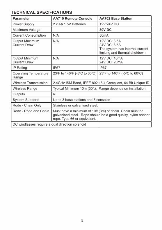
TECHNICAL SPECIFICATIONSParameter AA710 Remote Console AA702 Base StationPower Supply 2 x AA 1.5V Batteries 12V/24V DCMaximum Voltage 30V DCCurrent Consumption N/A 50mAOutput MaximumCurrent Draw
N/A 12V DC: 3.5A 24V DC: 3.5AThe system has internal current limiting and thermal shutdown.
Output Minimum Current Draw
N/A 12V DC: 10mA24V DC: 20mA
IP Rating IP67 IP67Operating Temperature Range
23oF to 140oF (-5oC to 60oC) 23oF to 140oF (-5oC to 60oC)
Wireless Transmission 2.4GHz ISM Band, IEEE 802.15.4 Compliant, 64 Bit Unique IDWireless Range Typical Minimum 10m (30ft). Range depends on installation.Outputs 6System Supports Up to 3 base stations and 3 consolesRode - Chain Only Stainless or galvanised steel.Rode - Rope and Chain Must have a minimum of 10ft (3m) of chain. Chain must be
galvanised steel. Rope should be a good quality, nylon anchor rope. Type 66 or equivalent.
DC windlasses require a dual direction solenoid

4
RADIO FREQUENCY COMPLIANCE
FCC Information:This device complies with Part 15 of the FCC Rules. Operation is subject to the following two conditions: (1) this device may not cause harmful interference and (2) this device must accept any interference received, including interference that may cause undesired operation.
Modifications not expressly approved by the manufacturer could void the user’s authority to operate this equipment.
This device generates, uses, and can radiate radio frequency energy and, if not installed and used in accordance with the manufacturer’s instructions, may cause harmful interference to radio communications.
ESTI Information (CE): This device is compliant with the essential requirements of the R&TTE Directive 99/5/EC, meeting the European harmonized EMC and low-voltage/safety standards.
ELECTROMAGNETIC COMPATIBILITY (EMC)
FCC Information: This device complies with CFR47 Part 15 of FCC Rules for Class B equipment.
ESTI Information (CE):This device meets the relevant standards set out in European Standard EN 60945:2002 for maritime navigation and radio communication equipment and systems. These standards are intended to provide reasonable protection against interference by other emission generating products on the boat. Compliance with these standards is no guarantee that interference will not occur in a particular installation. The installation instructions must be followed to minimise the potential for interference.
Note: If shielded cable is not used for the sensor connections this will compromise the EMC and may invalidate the warranty.
AA710 equipment (AA702 base station and AA710 remote console) must be installed at least 3ft (1m) away from any equipment transmitting or cables carrying radio signals eg VHF radios, modified sine wave inverters, cables and antennas or radar antennas; and at least 6ft (2m) away from any SSB equipment. AA702 cables must be installed at least 1.5ft (500mm) away from such items.

5
PART 2 INSTALLATION
Drilling the Deck: Before drilling into the deck, ensure there is nothing below the deck that could be damaged and that any hole you drill will not weaken the boat’s structure. Drill a hole 10.3mm (13/32”) diameter through the deck. Ensure this hole is directly in line with the sensor hole in the deckplate.
2.1 INSTALLATION TO OPERATE A WINDLASS
2.1.3 SENSOR INSTALLATION OVERVIEW
Vertical Windlasses: The sensor is fitted in the deckplate. Some deckplates are predrilled for the sensor. Others have a dimple or mark to show where the sensor should be fitted. If the windlass is not factory drilled, drill a hole 10.3mm (13/32”) diameter through the windlass deckplate. See the instructions for your specific windlass type.
Horizontal Windlasses: Sometimes it is not possible to fit the sensor to a horizontal windlass or it may need to be fitted by the windlass manufacturer. Before starting check with the AutoAnchor manufacturer or supplier that it is possible to fit the sensor to your windlass. You may need a special fitting.
2.1.2 MAGNET INSTALLATION OVERVIEW
Check before starting. Your chainwheel may be prefitted with a magnet or predrilled ready for you to fit the magnet.
Magnet Polarity: Not relevant when using the grey AA sensor (#9067) or a reed switch sensor. If retrofitting, using the black AA sensor (#9008), the south pole (marked side) of the magnet must face the sensor.
Magnet Seal: Insert the magnet into the hole and cover it with a minimum of 1mm of epoxy to protect it against corrosion. See Fig 1 on page 8.
Magnet Size and Position: Refer to the instructions for your specific windlass type.
2.1.1 MAGNET AND SENSOR INSTALLATION
PLEASE READ BEFORE COMMENCING INSTALLATION
Correct magnet and sensor installation is critical for successful AutoAnchor operation.
The AutoAnchor can be installed on vertical windlasses, drum winches and most horizontal windlasses. Installation differs depending on the windlass type and on the rode (all-chain or rope and chain). Please follow the instructions for your windlass and rode. If it is not possible to comply with these instructions please check with the AutoAnchor manufacturer or your supplier for other options or if you are not sure how to proceed.
See www.autoanchor.co.nz for contact information.

6
Part #9507 Male Field ConnectorPart #9508 Female Field ConnectorIf there is no plug on the sensor cable attach the AA field connector to the wires and use the connecting cable as above.
2.1.4 PLUG AND PLAY SENSOR CABLE
The AutoAnchor plug and play sensor cable is 2 core tinned shielded cable. It must be used to connect the sensor to the console unit. Ensure the connectors are firmly screwed together.
The warranty does not apply if the sensor cable plugs are removed.
The sensor cable is fitted with a female plug to connect direct to the male connector on the AA702 base station. If a longer length is required, sensor connecting cable, with a male plug at each end, is available in the following lengths:
6.5 m (21.33 ft) Part #950010 m (32.81 ft) Part #950115 m (49.21 ft) Part #950220 m (66.62 ft) Part #950325 m (82 ft) Part #950435 m (114.83 ft) Part #9514
A 2m male/female cable (Part #9505) plus a gender changer (Part #9510) will be required to connect the extension cable to the base station.
Field Connectors
Sensor Connection: The sensor is plugged direct into the AA702 base station. Do not leave the cable hanging loose, it must be tied in place with cable ties. Extension cable, gender changers and field connectors are available if required.
Sensor Plug
Fitting the Sensor: Do not force the sensor into the hole. Hammering the sensor head can damage the internal electronics. Ensure the sensor head is positioned so that it will not be hit by the chainwheel during windlass operation and that it is at least 300mm (1ft) away from the battery and motor cables. Secure the sensor using a good quality neutral cure silicone or a strong adhesive eg. Sikaflex 291 or 3M 5200.
Connecting 2 cables together:
If you need to extend the cable length - 2 cables can be joined together using Part #9510 Gender Changer.
Antenna Plug

7
Dual Installation with Other AA ProductsUse the T adaptor Part #9506 and the 2m Male/Female extension cable Part #9505.
2.1.5 REED SWITCH SENSORS
Some windlasses are supplied pre-fitted with a reed switch sensor. Reed switch sensors must have a 10mm x 8mm magnet (#9061) and the gap between the reed switch sensor and the magnet must be a minimum of 3mm and a maximum of 5mm. This sensor requires a field connector.
The AutoAnchor will operate with a reed switch sensor for all-chain rode. If using combination rope and chain rode the reed switch sensor provides a reasonably accurate count of rode deployed but on retrieval the display may be incorrect because it cannot allow for the stretch in the rope.
For an accurate rope and chain count, the reed switch sensor should be replaced with the AA grey sensor (#9067).
2.1.6 SENSOR TUNING
When the AutoAnchor is completely installed the sensor must be tuned. See the instructions on page 37.

8
Magnet Fit: Drill a hole 10.3mm (13/32”) diameter and 9.5mm (3/8”) deep to fit the magnet in the underside of a spoke in the bottom of the chainwheel. Cover the magnet with a minimum of 1 mm epoxy. The magnet should be aligned with the sensor. See Fig 1.
2.1.7 INSTALLATION ON A VERTICAL WINDLASS - CHAIN ONLY
Magnet Size: Standard size is 10mm x 8mmm (#9061). This may be replaced with the smaller 6mm x 4mm (#9009) magnet if required for your windlass.
Fig 1 - All sensors
Seal with minimum 1mm epoxy.
Magnet
Sensor
Gap Between the Sensor and Magnet:
Sensor Magnet Size Gap
AA Grey Sensor #9067 6mm x 4mm Minimum 3mm - Maximum 30mm
AA Grey Sensor #9067 10mm x 8mm Minimum 3mm - Maximum 50mm
AA Black Sensor #9008 All Magnets Minimum 3mm - Maximum 8mm
Reed Switch Sensor 10mm x 8mm Minimum 3mm - Maximum 5mm
Chainwheel
Deckplate
Refer to the Overview Notes on page 5 before starting installation.
Sensor Connection: Ideally the sensor should be plugged directly into the AA702 base station. If longer cable is required use the AA 2m male/female extension cable (Part #9505) or one of the AA standard male/male extension cables plus the 2m cable and a gender changer. Ensure the connectors are firmly screwed together. See the information on page 6.
Loose cable should be tied in place with cable ties and kept clear of chain.
Sensor Position: The AA black sensor and the reed switch sensor must be fitted direclty in line with the magnet in the chainwheel. See Fig 1 above. The AA grey sensor may be fitted up to 20mm out of alignment. The gap between the sensor and magnet must be as per the table below.
Note: If it is not possible to align the sensor and magnet exactly the AA grey sensor may be fitted up to 20mm out of alignment. The AA black sensor and the reed switch sensor must be directly aligned.

9
Magnet Fit: Some windlasses are predrilled and others need a special fit. Please check with your supplier. The usual fit is as follows: Drill a hole 10.3mm (13/32”) diameter and 9.5mm (3/8”) deep into a spoke in the top of the chainwheel. Cover the magnet with a minimum of 1mm epoxy. The magnet and sensor must be aligned so that the anchor rode passes between them. See Figs 2 & 3.
Sensor
Magnet
Fig 2 Fig 4
Seal with minimum 1mm epoxy.
Magnet
2.1.8 INSTALLATION ON A VERTICAL WINDLASS - ROPE & CHAIN
For an accurate rope and chain count, the rode must run between the sensor and magnet. If your windlass is prefitted with a magnet in the bottom of the chainwheel you need to remove it and fit a new magnet in the top of the chainwheel. Refer to Figs 2-4.
Magnet Size: 10mm X 8mm magnet (#9061). An 8mm x 6mm magnet (#9052) may be used on smaller windlasses. Check with your supplier.
Sensor Position: The sensor must be fitted into the deckplate within the sensor position range at the stern end of the windlass (See Fig 5). It must also be aligned with the magnet so that the rode passes between the sensor and the magnet. The centre of the magnet and the centre of the sensor may be up to 10mm out of direct alignment (See Fig 3). The gap between the sensor and magnet must be as per the table below.
Chainwheel
Deckplate
Fig 3
Sensor & Magnet may be up to 10mm out of direct alignment
10mm
Sensor
Magnet
Sensor
Magnet
Fig 5
Sensor Position Rope & Chain Vertical Windlasses
Gap Between the Sensor and MagnetSensor Magnet Size GapAA Grey Sensor #9067 8mm x 6mm Minimum 30mm - Maximum 44mm
AA Grey Sensor #9067 10mm x 8mm Minimum 35mm - Maximum 50mm
Refer to the Overview Notes on page 5 before starting installation.
Sensor Connection: If longer cable is required the AutoAnchor plug and play sensor extension cable must be used to connect the sensor to the AA702 base station. Ensure the connectors are firmly screwed together. See the information on page 6. Loose cable should be tied in place with cable ties and kept clear of chain.
Sensor Position Range
90o
Bow
Ste
rn
Rode
Anchor Locker
Chainwheel

10
2.1.9 INSTALLATION ON A HORIZONTAL WINDLASS - CHAIN ONLY
Fig 6Magnet in rim of chainwheel and standard sensor in sensor holder screwed to the deck
Magnet & Sensor Fitting for Chain Only Horizontal Windlasses
Magnet Size: 6mm x 4mm magnet (#9009).
Magnet Fit: If your windlass is not predrilled drill a hole 6.5mm (1/4”) diameter and 5mm (3/16”) deep in the edge of the chainwheel. Cover the magnet with a minimum of 1mm epoxy.
Gap Between the Sensor and Magnet: Sensor Magnet Size Gap
AA Grey Sensor #9067 6mm x 4mm Minimum 3mm - Maximum 30mm
AA Grey Sensor #9067 10mm x 8mm Minimum 3mm - Maximum 50mm
AA Black Sensor #9008 All Magnets Minimum 3mm - Maximum 8mm
Reed Switch Sensor 10mm x 8mm Minimum 3mm - Maximum 5mm
Sensor Connection: If longer cable is required the AutoAnchor plug and play sensor extension cable must be used to connect the sensor to the AA702 base station. Ensure the connectors are firmly screwed together. See the information on page 6.
Loose cable should be tied in place with cable ties and kept clear of chain.
Refer to the Overview Notes on page 5 before starting installation. It is not possible to set out a single installation method for horizontal windlasses. The sensor may be fitted inside the windlass or you may need a sensor holder (Part #9110). See Fig 6 below. Often the sensor and magnet can only be fitted by the windlass manufacturer.
Sensor Holder
Sensor
Magnet
Sensor Position: The AutoAnchor sensor may be fitted using a sensor holder fixed to the deck to sit under the chainwheel (See Fig 6). The AutoAnchor sensor holder (#9110) is not included in the standard kit. Check with your supplier if you need this. The AA black sensor and the reed switch sensor must be fitted directly in line with the magnet in the chainwheel. The AA grey sensor may be fitted up to 20mm out of alignment. The gap between the sensor and magnet must be as per the table below.
11
Before starting check with the AutoAnchor manufacturer, or supplier, that it is possible to fit the sensor and magnet to your horizontal windlass.
For an accurate rope count the rode must run between the sensor and magnet. On a horizontal windlass the magnet and sensor must be fitted by the windlass manufacturer.
If it is not possible to have the sensor and magnet fitted to achieve this you can use the chain only horizontal windlass installation above. This provides an accurate count of rode deployed but during retrieval the display may be incorrect because it cannot allow for the stretch in the rope.
2.1.10 INSTALLATION ON A HORIZONTAL WINDLASS - ROPE & CHAIN
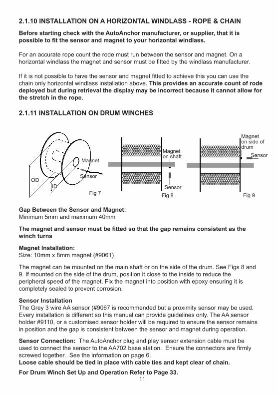
2.1.11 INSTALLATION ON DRUM WINCHES
For Drum Winch Set Up and Operation Refer to Page 33.
Gap Between the Sensor and Magnet:Minimum 5mm and maximum 40mm
The magnet and sensor must be fitted so that the gap remains consistent as the winch turns
Magnet Installation:Size: 10mm x 8mm magnet (#9061)
The magnet can be mounted on the main shaft or on the side of the drum. See Figs 8 and 9. If mounted on the side of the drum, position it close to the inside to reduce theperipheral speed of the magnet. Fix the magnet into position with epoxy ensuring it is completely sealed to prevent corrosion.
Sensor Installation The Grey 3 wire AA sensor (#9067 is recommended but a proximity sensor may be used. Every installation is different so this manual can provide guidelines only. The AA sensor holder #9110, or a customised sensor holder will be required to ensure the sensor remains in position and the gap is consistent between the sensor and magnet during operation.
Sensor Connection: The AutoAnchor plug and play sensor extension cable must be used to connect the sensor to the AA702 base station. Ensure the connectors are firmly screwed together. See the information on page 6.Loose cable should be tied in place with cable ties and kept clear of chain.
Magnet on side of drum
Magnet on shaft
Sensor
Sensor
Fig 8 Fig 9
Magnet
Sensor
Fig 7
ODID
12
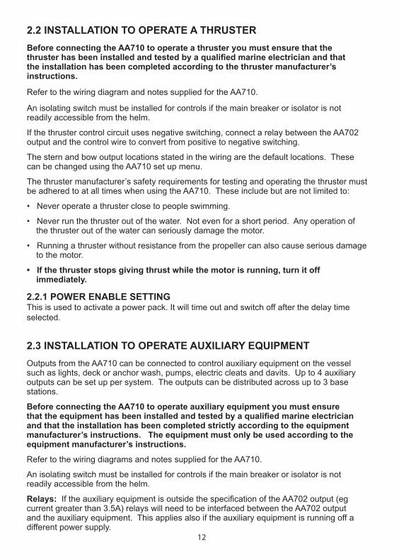
2.2 INSTALLATION TO OPERATE A THRUSTER Before connecting the AA710 to operate a thruster you must ensure that the thruster has been installed and tested by a qualified marine electrician and that the installation has been completed according to the thruster manufacturer’s instructions.
Refer to the wiring diagram and notes supplied for the AA710.
An isolating switch must be installed for controls if the main breaker or isolator is not readily accessible from the helm.
If the thruster control circuit uses negative switching, connect a relay between the AA702 output and the control wire to convert from positive to negative switching.
The stern and bow output locations stated in the wiring are the default locations. These can be changed using the AA710 set up menu.
The thruster manufacturer’s safety requirements for testing and operating the thruster must be adhered to at all times when using the AA710. These include but are not limited to:
• Never operate a thruster close to people swimming.
• Never run the thruster out of the water. Not even for a short period. Any operation of the thruster out of the water can seriously damage the motor.
• Running a thruster without resistance from the propeller can also cause serious damage to the motor.
• If the thruster stops giving thrust while the motor is running, turn it off immediately.
2.2.1 POWER ENABLE SETTINGThis is used to activate a power pack. It will time out and switch off after the delay time selected.
2.3 INSTALLATION TO OPERATE AUXILIARY EQUIPMENTOutputs from the AA710 can be connected to control auxiliary equipment on the vessel such as lights, deck or anchor wash, pumps, electric cleats and davits. Up to 4 auxiliary outputs can be set up per system. The outputs can be distributed across up to 3 base stations.
Before connecting the AA710 to operate auxiliary equipment you must ensure that the equipment has been installed and tested by a qualified marine electrician and that the installation has been completed strictly according to the equipment manufacturer’s instructions. The equipment must only be used according to the equipment manufacturer’s instructions.
Refer to the wiring diagrams and notes supplied for the AA710.
An isolating switch must be installed for controls if the main breaker or isolator is not readily accessible from the helm.
Relays: If the auxiliary equipment is outside the specification of the AA702 output (eg current greater than 3.5A) relays will need to be interfaced between the AA702 output and the auxiliary equipment. This applies also if the auxiliary equipment is running off a different power supply.
13
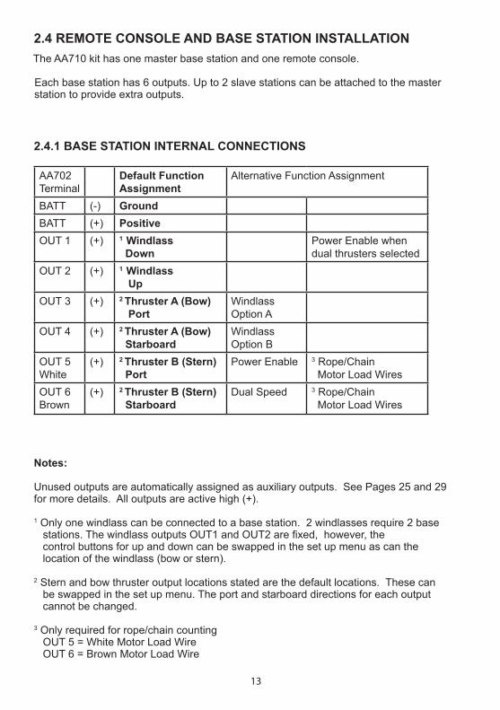
AA702Terminal
Default FunctionAssignment
Alternative Function Assignment
BATT (-) GroundBATT (+) PositiveOUT 1 (+) 1 Windlass
DownPower Enable when dual thrusters selected
OUT 2 (+) 1 Windlass Up
OUT 3 (+) 2 Thruster A (Bow) Port
WindlassOption A
OUT 4 (+) 2 Thruster A (Bow) Starboard
Windlass Option B
OUT 5White
(+) 2 Thruster B (Stern) Port
Power Enable 3 Rope/Chain Motor Load Wires
OUT 6Brown
(+) 2 Thruster B (Stern) Starboard
Dual Speed 3 Rope/Chain Motor Load Wires
2.4.1 BASE STATION INTERNAL CONNECTIONS
Notes:
Unused outputs are automatically assigned as auxiliary outputs. See Pages 25 and 29 for more details. All outputs are active high (+).
1 Only one windlass can be connected to a base station. 2 windlasses require 2 base stations. The windlass outputs OUT1 and OUT2 are fixed, however, the control buttons for up and down can be swapped in the set up menu as can the location of the windlass (bow or stern).
2 Stern and bow thruster output locations stated are the default locations. These can be swapped in the set up menu. The port and starboard directions for each output cannot be changed.
3 Only required for rope/chain counting OUT 5 = White Motor Load Wire OUT 6 = Brown Motor Load Wire
The AA710 kit has one master base station and one remote console.
Each base station has 6 outputs. Up to 2 slave stations can be attached to the master station to provide extra outputs.
2.4 REMOTE CONSOLE AND BASE STATION INSTALLATION

14
2.4.2 REMOTE CONSOLE INSTALLATION
The remote console is supplied with a cradle and a cover. One remote console can operate multiple base stations. The console has a loop to allow for a wrist or belt lanyard.
The cradle should be mounted on a flat surface at least 3ft (1m) away from any equipment transmitting or cables carrying radio signals eg VHF radios, cables and antennas or radar antenna and at least 6ft (2m) away from any SSB equipment.
The remote console is sealed to IP67.
Up to 4 remote consoles can be connected to a system.
Two alkaline AA 1.5V batteries are required to operate the console. These are prefitted in new products.
To maintain the IP67 waterproof seal through the cable gland a tinned, marine grade multi core cable must be used and the base station must be mounted so that the cables extend below the unit when fixed to the wall.
• the lid can be removed easily during operation.• the LED indicators can be seen during operation.• the best reception is available (see Fig 10).• the cables extend below the unit when fixed to the wall to avoid condensation entering through the cable gland.
Cradle Loop for Lanyard
Cover
LED Indicators
2.4.3 BASE STATION
Wireless CommunicationBest reception for the wireless signal is on the top or sides of the base station as per the diagram. Alloy, steel or carbon fibre will restrict the wireless communication. An antenna may need to be fitted if wireless communication is impeded. AA710 Antenna Part # 9403.
Up to 3 base stations can be connected to a system. When operating a windlass, the base station should be mounted close to the windlass, in a position where:
Fig 10
Bes
t r
eception top or sides
15
12V or 24V DC power supply is required to the AA702 base station.
Check battery polarity before connecting power and ensure output terminals will not short.
Refer to the manufacturer’s specifications for fuse/breaker, isolator and main power cable specifications, for the equipment being controlled by the AA710.
Ensure any fuse/breaker on the control circuit has a rating applicable to the current loads connected to the outputs. (AA702 Output maximum is 3.5 Amps). An additional isolating switch should be installed for controls if the main breaker or isolator is not readily acessible from the helm.
Multiple battery bank negative terminals must be permanently connected together to become the common negative return (ground).
2.5.1 WINDLASS INSTALLATIONSPower supply to the AA702 base station must be from the windlass control circuit, along with all other windlass controls eg. toggle switch, remote switches, deck switches, other AutoAnchor devices. Power supply must not be from the motor positive near the windlass.
2.5.2 MULTIPLE BASE STATION INSTALLATIONSThe master base station must be powered up when using a slave base station application. Separate base stations may be powered from separate supplies, however, if 2 products are connected to the same base station they must be powered by the same supply, or relays must be used as a means of isolation. To maintain power to the windlass it is recommended that the windlass be attached to the master base station.
THE POWER SUPPLY MUST BE DISCONNECTED WHEN INSTALLING, CONNECTING OR CHANGING THE WIRING
2.5 POWER SUPPLY
2.6 VOLTAGE LEVELS
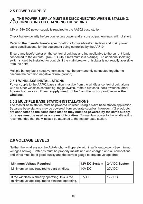
Neither the windlass nor the AutoAnchor will operate with insufficient power. (See minimum voltages below). Batteries must be properly maintained and charged and all connections and wires must be of good quality and the correct gauge to prevent voltage drop.
Minimum Voltage Required 12V DC System 24V DC SystemMinimum voltage required to start windlass 10V DC 20V DC
If the windlass is already operating, this is the minimum voltage required to continue operating.
6V DC 12V DC

16
CABLE SPECIFICATIONS
An appropriate multi-core cable must be used to maintain the cable gland seal into the base station. Total Length Cable SizeCable from AA702 Base Station to the Power SupplyLess than 8m (26ft) 1.5mm2 (AWG16)8m (26ft) - 11m (36ft) 2.0mm2 (AWG14)11m (36ft) - 17m (56ft) 2.5mm2 (AWG12)Cable from AA702 Base Station to OutputsLess than 10m (33ft) 1.5mm2 (AWG16)10m (33ft) and 20 m (66ft) 2.0mm2 (AWG14)20m (66ft) and 40m (132ft) 2.5mm2 (AWG12)Cable from Motor Load WiresUp to 30.5m (100ft) 1.0mm2 (AWG18)
2.7 WIRING
2.7.1 MOTOR LOAD WIRES (BROWN AND WHITE) OUTPUTS 5 & 6
Rope & Chain Counting: The brown and white wires must be connected direct to the windlass motor terminals for rope & chain counting. A 1000 Ohm resister must be fitted near the motor terminal for short circuit protection. The motor load terminators supplied in the kit have motor terminal connectors with a 1000 Ohm resistor prefitted.
If the AA710 is fitted to an all-chain windlass, a thruster or auxiliary equipment. Outputs 5 and 6 can be used for other options.
Interlock protection is included in the system. Do not fit diodes or interlock devices to outputs as these will prevent the system from operating correctly.
All battery and motor cables must be ring type, insulated to prevent short circuits and installed no closer than 1ft (300mm) away from the sensor head.
To reduce the potential for interference all cables must be located at least 1.5ft (500mm) away from any equipment transmitting or cables carrying radio signals eg VHF or SSB radios, cables and antennas or radar antennas.
Do not leave cables hanging loose, they must be tied in place with cable ties.
2.7.2 MULTIPLE AUTOANCHOR INSTALLATIONS It is important when wiring multiple AutoAnchor products that potential differences do not occur along the ground connection. This can cause incorrect counting. Ensure AA560 and AA150 consoles and AA702 base stations are star grounded, and that there are no other high current paths between consoles. All wiring for multiple installations is run in parallel. Refer to wiring diagrams for further details.
17
2.7.2 MULTIPLE AUTOANCHOR INSTALLATIONS It is important when wiring multiple AutoAnchor products that potential differences do not occur along the ground connection. This can cause incorrect counting. Ensure AA560 and AA150 consoles and AA703 base stations are star grounded, and that there are no other high current paths between consoles. All wiring for multiple installations is run in parallel. Refer to wiring diagrams for further details.
2.7.4 PLUG & PLAY SENSOR CONNECTIONS
The AA703 Base Station and the sensor are prefitted with connector plugs. The 2m sensor cable plugs direct into the base station. Extension cables are available. See page 5 for plug and play sensor cable information.
2.7.5 CONNECTING THE CABLES INTO THE BASE STATION
Remove the lid from the AA703 base station. Feed the multi-core cable through the waterproof gland. Connect the cables to the terminal block, using a screwdriver to press down and open each terminal as required. (See the photograph below). Tighten the cable gland. Replace the lid.
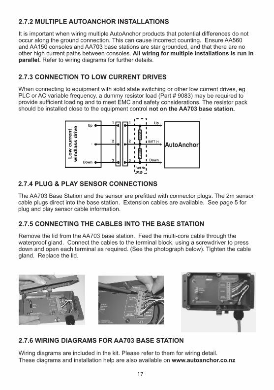
2.7.3 CONNECTION TO LOW CURRENT DRIVES
When connecting to equipment with solid state switching or other low current drives, eg PLC or AC variable frequency, a dummy resistor load (Part # 9083) may be required to provide sufficient loading and to meet EMC and safety considerations. The resistor pack should be installed close to the equipment control not on the AA703 base station.
2.7.6 WIRING DIAGRAMS FOR AA703 BASE STATION
Wiring diagrams are included in the kit. Please refer to them for wiring detail.These diagrams and installation help are also available on www.autoanchor.co.nz
UpUp
DownDown
BATT (-) -
1
2 3
1000
R10
00R
1
2 3
Lo
w c
urr
en
tw
ind
lass d
rive
Part No 9515
AutoAnchor

18
3.1 USING THE AUTOANCHOR BUTTONS On. Scroll: Menu/Numbers/Up/Down. Mode/Select/Enter/Save. Escape or Back. Hold together to access the Set up menu. Hold for 2 seconds to disable the lock. Hold for 1 second to toggle between modes eg windlass to thruster. Control the windlass. Control Options A & B, Thruster and Auxiliary outputs. Hold for 6 seconds to turn off.
Set up includes registering the wireless interface and calibrating the AA710 system for the equipment it is to control on the boat. The AA710 must be tested with all the equipment it is to control to ensure it is working correctly.
3.2.1 SYSTEM OVERVIEW
The AA710 kit is supplied with 1 x AA710 remote console and 1 x AA702 master base station. Each console and base station has a unique ID and the units must be registered to each other to operate the system. If extra outputs are required up to 2 additional base stations, known as slave stations, may be added into the system. Up to 4 consoles can be registered to operate a system. Follow the instructions to register the consoles and base stations.
3.2 WIRELESS INTERFACE SET UP
3.2.2 REGISTRATION SWITCHLocated inside the base station. Use to register the base station to the console and to register a slave to the master base station. See the instructions over.
3.2.3 LED INDICATORS System (Red) Steady red indicates power is on. Flashing continuously indicates registration state is active. Times out after 5 minutes. Flashing a slow pulse indicates sensor is connected when the windlass is turning.
PART 3 SET UP
Network (Green) Steady green indicates the base station is a master station. Off indicates the base station is a slave (See instructions to connect a slave station below).
Comms (Yellow) Flashing indicates data is received.
Registration Switch

19
3.2.5 REGISTER REMOTE CONSOLES TO THE BASE STATIONS
Each console must be registered separately.
1. Turn off all consoles.2. Turn on the power to all base stations. 3. Unscrew and remove the cover from the master base station.4. Press the Mode button to turn on the remote console. The screen will tell you to “Press the register switch on the master base station”.5. Press and release the registration button. The green LED will stay on. The red LED will flash to indicate the connection is registering. 6. Registration is automatic. The screen will show that the system is getting the network information and then that the console has been successfully registered to the base station. This could take up to 30 seconds.7. Press the Mode button to select OK. The console will return to the set up screen ready to set up the system functions. 8. If you have more than 1 console to register to the base station repeat the steps above ensuring the first console is turned off before you start. 9. When finished replace the lid on the base station.
3.2.6 TO TURN THE AA710 REMOTE CONSOLE OFF AFTER REGISTRATION
Press the left arrow to escape from Setup to the default start up screen. Press the Mode button to display the menu. Scroll to Off. Select Off.
Note: The AA710 remote console automatically turns off after 5 minutes without use. The Auto Off Time can be changed from between 4 to 20 minutes in the Setup menu. See page 23. If you have more than 1 console you must set the time for each console.
3.2.4 TURN THE AA710 SYSTEM ON FOR THE FIRST TIME Ensure the AA702 base station is powered up.
Press the Mode button on the AA710 remote console to turn it on. Because the system is not yet set up, the screen will tell you to press the registration switch on the master base station. See instructions below to register the console to to the base station.

20
3.2.7 ADD EXTRA BASE STATIONS (SLAVES)
Slave base stations are added to supply the outputs for additional functions. All base stations are supplied as masters and they must be reset to operate as a slave. Decide which base station is to remain the master and then follow the directions below to register the slave stations. To maintain power to the windlass it is recommended that it be attached to the master base station.
1. Ensure all remote consoles are turned off.2. Unscrew and remove the lid from both base stations. 3. Turn on the power to both base stations. The green LED will light up on both stations.4. Slave: Hold down the registration button, on the slave station, for 6 seconds until the green LED turns off. Then release the button. The red LED will flash to indicate the unit is in registration mode.5. Master: Press and release the registration button. The green LED will stay on. The red LED will flash to indicate the connection is registering. Registration is complete when the red LED stops flashing on both base stations.6. Repeat the process to add further slave stations as required.7. Before replacing the lids on the base stations you need to record the unique ID number for each base station. The ID is on the white label next to the registration switch. This number is the same as the last 4 digits on the bar code label on the outside of the base station. Master Base Station ID ______________ Slave Station 1 ID ______________ Slave Station 2 ID ______________ Note: The AA710 console will automatically update and register the additional slave station when it is next turned on.
801DBase Station ID
3.2.8 DEREGISTERING A BASE STATION
If a base station is removed or replaced it must be deregistered from the system. To do this:Turn the power off to the affected base station and disconnect it. Record the ID number. Power up the master base station. Turn off the AA710 remote console. Hold together to display the Set Up Menu. It may take up to 20 seconds for the network information to be updated. Select Modes. Scroll to the base station ID. Select the base station. The screen will show Not Found. Select Deregister. Select Deregister again. This will remove the registration and restart the system.
If you have deregisterered a slave station no further action is required.
If you have deregistered a master base station the system must be set up again as if it is a new system.
815A803D
21
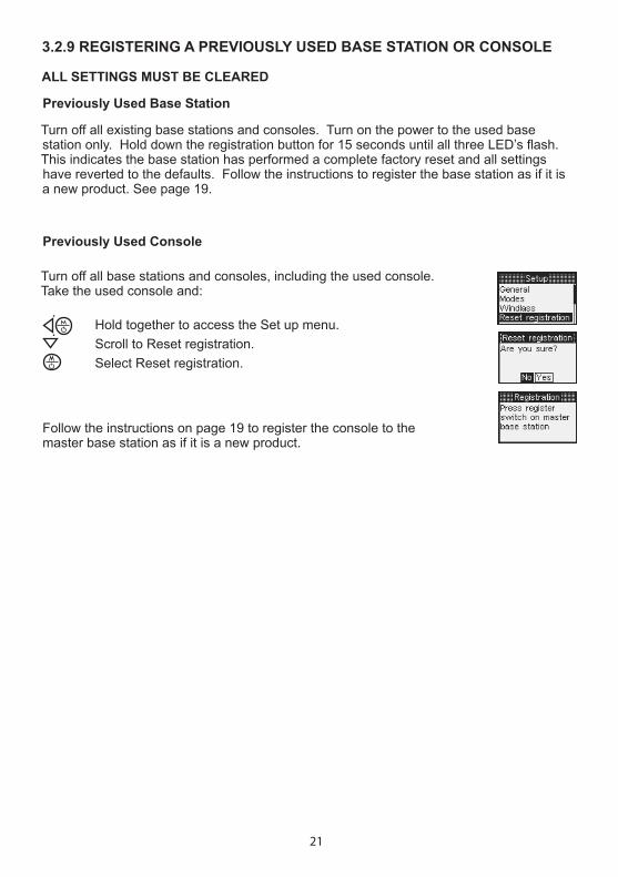
Previously Used Console
Turn off all base stations and consoles, including the used console.Take the used console and: Hold together to access the Set up menu. Scroll to Reset registration. Select Reset registration.
Follow the instructions on page 19 to register the console to the master base station as if it is a new product.
3.2.9 REGISTERING A PREVIOUSLY USED BASE STATION OR CONSOLE
ALL SETTINGS MUST BE CLEARED
Previously Used Base Station
Turn off all existing base stations and consoles. Turn on the power to the used base station only. Hold down the registration button for 15 seconds until all three LED’s flash. This indicates the base station has performed a complete factory reset and all settings have reverted to the defaults. Follow the instructions to register the base station as if it is a new product. See page 19.
22
Hold together to display the Set up menu.Select General.
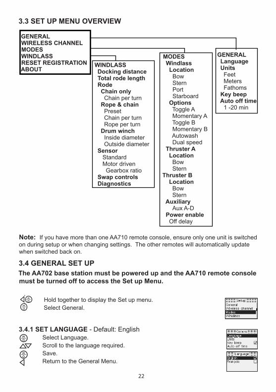
WINDLASS Docking distance Total rode length Rode Chain only Chain per turn Rope & chain Preset Chain per turn Rope per turn Drum winch Inside diameter Outside diameter Sensor Standard Motor driven Gearbox ratio Swap controls Diagnostics
MODES Windlass Location Bow Stern Port Starboard Options Toggle A Momentary A Toggle B Momentary B Autowash Dual speed Thruster A Location Bow SternThruster B Location Bow Stern Auxiliary Aux A-D Power enable Off delay
GENERAL Language Units Feet Meters Fathoms Key beep Auto off time 1 -20 min
3.3 SET UP MENU OVERVIEW
The AA702 base station must be powered up and the AA710 remote console must be turned off to access the Set up Menu.
Note: If you have more than one AA710 remote console, ensure only one unit is switched on during setup or when changing settings. The other remotes will automatically update when switched back on.
3.4 GENERAL SET UP
GENERALWIRELESS CHANNELMODESWINDLASSRESET REGISTRATIONABOUT
3.4.1 SET LANGUAGE - Default: English Select Language. Scroll to the language required. Save. Return to the General Menu.
23
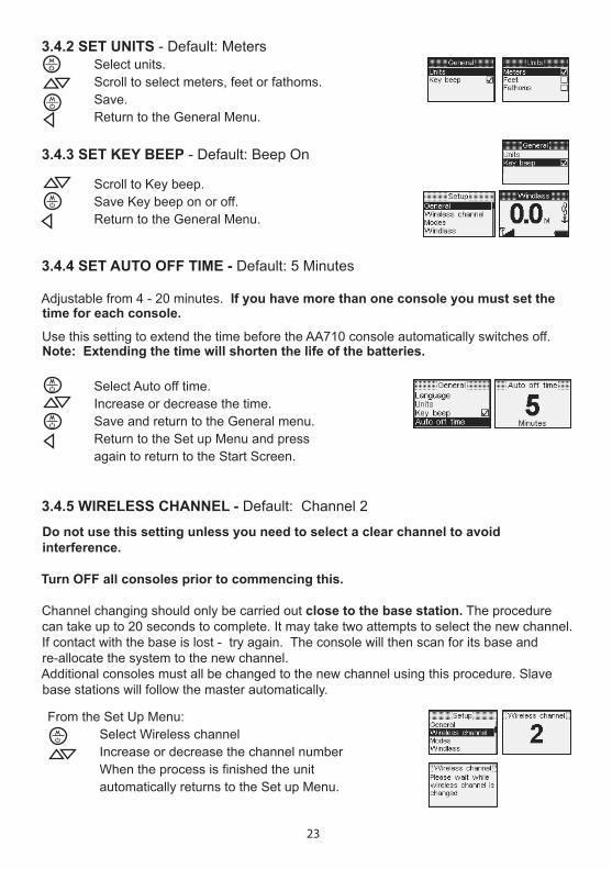
3.4.3 SET KEY BEEP - Default: Beep On
Scroll to Key beep. Save Key beep on or off. Return to the General Menu.
3.4.2 SET UNITS - Default: Meters Select units. Scroll to select meters, feet or fathoms. Save. Return to the General Menu.
3.4.4 SET AUTO OFF TIME - Default: 5 Minutes
Adjustable from 4 - 20 minutes. If you have more than one console you must set the time for each console.
Use this setting to extend the time before the AA710 console automatically switches off. Note: Extending the time will shorten the life of the batteries.
Select Auto off time. Increase or decrease the time. Save and return to the General menu. Return to the Set up Menu and press again to return to the Start Screen.
Do not use this setting unless you need to select a clear channel to avoid interference.
Turn OFF all consoles prior to commencing this.
Channel changing should only be carried out close to the base station. The procedure can take up to 20 seconds to complete. It may take two attempts to select the new channel. If contact with the base is lost - try again. The console will then scan for its base and re-allocate the system to the new channel.Additional consoles must all be changed to the new channel using this procedure. Slave base stations will follow the master automatically.
3.4.5 WIRELESS CHANNEL - Default: Channel 2
From the Set Up Menu: Select Wireless channel Increase or decrease the channel number When the process is finished the unit automatically returns to the Set up Menu.

24
3.5 MODES SET UPThe AA702 base station must be powered up and the AA710 remote console must be turned off to access the Set up Menu.
The AA710 system can be set up to operate your choice of equipment on the boat. The standard kit has one master base station and one console. Each base station has 6 outputs. Up to 2 slave stations can be attached to the master station to provide extra outputs. The default system is 1 windlass located on the bow. The options available are explained below, followed by examples of system setups. See also the table of output options on page 26.
3.5.1 WINDLASS SETTINGS
Allocate the outputs for windlasses and anchoring operations in the Modes menu.
3.5.1.1 Windlass Location - Outputs 1 and 2 (Default is 1 windlass)
If you have more than one windlass you will need to allocate the outputs and enter the windlass locations into the system. An individual base station is required for each windlass . The windlass outputs must be Output 1 and Output 2. The outputs are operated using the up and down buttons.
3.5.1.2 Windlass Options - Outputs 3 and 4
Option A and B can be used from the Windlass page for functions associated with anchoring. For example: decklights, deck wash, anchor stow, power cleat.
Option A is operated using the left arrow button and controls Output 3.
Option B is operated using the right arrow button and controls Output 4.
Both options can be set as momentary or toggle switches.
3.5.1.3 Autowash - Output 5
Turns on the anchor wash pump automatically when the anchor is retrieved.
3.5.1.4 Dual Speed - Output 6
Use to operate a windlass with a dual speed motor. Dual speed is controlled by the right arrow button and sends a Fast/Slow signal to Output 6.
3.5.2 THRUSTER SETTINGS - Outputs 3, 4, 5 and 6
The default locations can be swapped in the Setup menu. The port and starboard directions for each output cannot be changed.
Allocate the outputs and set the thruster location in the Modes menu. The thrusters are operated from the thruster page using the left and right arrow buttons.
Thruster ADefault Location Bow
Output 3 - PortOutput 4 - Starboard
Thruster BDefault Location Stern
Output 5 PortOutput 6 - Starboard
25
3.5.3 AUXILIARY SETTINGS - All Outputs
Any spare output can be used as an auxiliary output with a maximum of 4 per system. These outputs can be used to operate any equipment on the boat that requires switching for example, to open and close transom doors or hatches, operate electric motors for cleats, to raise and lower davits, to switch on lights and pumps. The auxiliary outputs are operated in the auxiliary menu. Any button can be allocated to an auxiliary output. Switches can be momentary or toggle. Allocate the outputs for auxiliary equipment in the Modes menu.
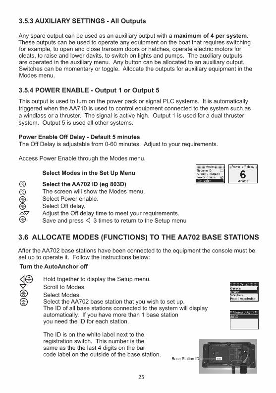
3.5.4 POWER ENABLE - Output 1 or Output 5This output is used to turn on the power pack or signal PLC systems. It is automatically triggered when the AA710 is used to control equipment connected to the system such as a windlass or a thruster. The signal is active high. Output 1 is used for a dual thruster system. Output 5 is used all other systems.
Power Enable Off Delay - Default 5 minutesThe Off Delay is adjustable from 0-60 minutes. Adjust to your requirements.
Access Power Enable through the Modes menu.
Select Modes in the Set Up Menu
Select the AA702 ID (eg 803D) The screen will show the Modes menu. Select Power enable. Select Off delay. Adjust the Off delay time to meet your requirements. Save and press 3 times to return to the Setup menu
3.6 ALLOCATE MODES (FUNCTIONS) TO THE AA702 BASE STATIONS
After the AA702 base stations have been connected to the equipment the console must be set up to operate it. Follow the instructions below:Turn the AutoAnchor off
Hold together to display the Setup menu. Scroll to Modes. Select Modes. Select the AA702 base station that you wish to set up. The ID of all base stations connected to the system will display automatically. If you have more than 1 base station you need the ID for each station. The ID is on the white label next to the registration switch. This number is the same as the the last 4 digits on the bar code label on the outside of the base station.
803D
801DBase Station ID

26
A system with one base station (6 outputs) can operate:• 1 windlass plus a thruster and 2 optional functions eg a deck wash, deck light,
anchor stow or electric cleat.• 1 dual speed windlass, plus a thruster with power enable.• or 1 windlass plus 4 auxiliary functions.• or 1 windlass plus 2 thrusters.• or 4 auxiliary outputs.
A system with two base stations (12 outputs) can operate:
• 1 windlass plus 2 thrusters and up to 4 auxiliary or optional functions. • 2 windlasses plus 2 thrusters plus up to 4 auxiliary or optional functions. • unused outputs can be used for auxiliary functions (maximum 4).
Example system setups are overleaf.
Follow the screen prompts to select the functions for each base station. Note: When selecting the base station this message may appear for a few seconds. If it stays for longer than 30 seconds the base station may not be powered up or it may be too far away.
3.6.1 BASE STATION OUTPUTSAA702Terminal
Default FunctionAssignment
Alternative Function Assignment
BATT (-) GroundBATT (+) PositiveOUT 1 (+) 1 Windlass
DownPower Enable when dual thrusters selected
OUT 2 (+) 1 Windlass Up
OUT 3 (+) 2 Thruster A (Bow) Port
WindlassOption A
OUT 4 (+) 2 Thruster A (Bow) Starboard
Windlass Option B
OUT 5White
(+) 2 Thruster B (Stern) Port
Power Enable 3 Rope/Chain Motor Load Wires
OUT 6Brown
(+) 2 Thruster B (Stern) Starboard
Dual Speed 3 Rope/Chain Motor Load Wires
Notes:
Unused outputs are automatically assigned as auxiliary outputs. See Pages 25 and 29 for more details. All outputs are active high (+).1 Only one windlass can be connected to a base station. 2 windlasses require 2 base stations. The windlass outputs OUT1 and OUT2 are fixed, however, the control buttons for up and down can be swapped in the set up menu as can the location of the windlass (bow or stern).2 Stern and bow thruster output locations stated are the default locations. These can be swapped in the set up menu. The port and starboard directions for each output cannot be changed.3 Only required for rope/chain counting OUT 5 = White Motor Load Wire OUT 6 = Brown Motor Load Wire

27
EXAMPLE 2A dual speed windlass, a bow thruster with power enable. This set up uses a single AA702 base station.
Select Modes in the Set Up Menu Select the AA702 ID (eg 803D) The screen will show the Modes menu.
Windlass Follow the steps in example 1 above for the windlass settings. Under Options select dual speed. Return to Modes.
Thruster Scroll to Thruster. Select Thruster. Select Location. Scroll to the thruster location. Select the thruster location. Return to Modes. Select Power enable. Select Off delay. Adjust the Off delay time to meet your requirements. Press 3 times to return to the start screen.
Modes
803D
EXAMPLE 1A windlass, Option A (anchor light) and Option B (manual anchor wash). This set up uses a single AA702 base station. Select Modes In the Set Up Menu
Select the AA702 ID (eg 803D) The screen will show the Modes menu.
Windlass Select Windlass. Select Location. Scroll to the windlass location. Select the windlass location. Return to Modes.
Options Select Options. Select Toggle A for the anchor light. Select Toggle B for manual anchor wash. Return to Modes. Press 3 times to return to the start screen.
803D

28
EXAMPLE 4Two windlasses, a bow and stern thruster with power enable and 2 optional or auxiliary functions. This set up uses two AA702 base stations.It is important to select the locations for the windlasses and the thrusters.
Select Modes In the Set Up Menu
Windlass 1 and Thruster 1 Select the AA702 Base Station ID for Windlass 1 and Thruster 1 (eg 803D) The screen will show the Modes menu.
Follow the steps in Example 2 for Windlass 1, Thruster A and Power Enable. Power enable will apply to both thrusters. Ensure you select the location for the windlass and the thruster. Return to the Select AA702 Screen.
Windlass 2 and Thruster 2 Scroll to the AA702 ID for Windlass 2 and Thruster B (eg 815A). Select the AA702 ID for Windlass 2 and Thruster 2 The screen will show the Modes menu. Follow the steps in Example 2 for Windlass 2 and Thruster B. Ensure you select the location for the windlass and the thruster. Return to Modes. Power Enable has already been set up for both thrusters. Press 3 times to return to the start screen. Optional and Auxiliary Functions Still Available are: Base Station 803D: Output 6 Auxiliary Base Station 815A: Output 3 Option A or Auxiliary Output 4 Option B or Auxiliary
815A803D
803D815A
EXAMPLE 3Two dual speed windlasses, Option A (anchor light), auto wash. This set up uses two AA702 base stations. It is important to select the windlass location when setting up for 2 windlasses. Select Modes In the Set Up Menu Windlass 1 Select the AA702 ID for Windlass 1 (eg 803D) The screen will show the Modes menu.
Follow the steps in Example 1 for Windlass 1. Select Toggle A (anchor light),dual speed and autowash. Ensure you select the windlass location. Return to the Setup Modes Screen. Windlass 2 Scroll to the AA702 ID for Windlass 2 (eg 815A). Select the AA702 ID for Windlass 2 The screen will show the Modes menu.
Follow the steps above for Windlass 2 and options. Ensure you select the windlass location. Return to Modes. Press 3 times to return to the start screen.
815A803D
803D815A
29
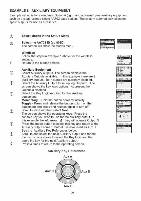
Scroll to Next and then select Next. The screen shows the operating keys. Press the console key you wish to use for the auxiliary output. In this example the left arrow key will operate Output 3. Press the mode button to select this key and return to the Auxiliary output screen. Output 3 is now listed as Aux C. See the Auxiliary Key References below. Scroll to and select the next Auxiliary output and repeat the instructions above to select the Key logic and the operating key for the next Auxiliary output. Press 4 times to return to the operating screen.
Auxiliary Key ReferencesAux A
Aux B
Aux C Aux D
EXAMPLE 5 - AUXILIARY EQUIPMENT
Select Modes in the Set Up Menu Select the AA702 ID (eg 803D) The screen will show the Modes menu.
Windlass Follow the steps in example 1 above for the windlass settings. Return to the Modes screen.
Auxiliary Equipment Select Auxiliary outputs. The screen displays the Auxiliary Outputs available. In this example there are 2 auxiliary outputs. Both ouputs are currently disabled. Select the Auxiliary Output to set up. eg Output 3. The screen shows the key logic options. At present the Output is disabled. Select the Key Logic required for the auxiliary equipment: Momentary - Hold the button down for activity. Toggle - Press and release the button to turn on the equipment and press and release again to turn off.
803D
Example set up is for a windlass, Option A (light) and autowash plus auxiliary equipment such as a cleat, using a single AA702 base station. The system automatically allocates spare outputs for use as auxiliaries.

30
Turn the AA710 remote console off. Hold together to access the Set up menu. Scroll to Windlass. Select Windlass.
3.6 WINDLASS SET UP FOR CHAIN COUNTING
For accurate chain counting you must set up the AutoAnchor with the following information for your windlass.
3.6.1 TO ACCESS THE WINDLASS SET UP
3.6.2 SET DOCKING DISTANCE Note: If the dual speed option is enabled the windlass will be in slow speed from this point.
Defaut = 1.5m or 4ft. Minimum setting = 1m or 3.3ft.This is the point during retrieval when the windlass will stop. Complete retrieval using manual operation.
Scroll to Docking distance. Select docking distance. Increase or decrease the docking distance. Save and return to Windlass Setup.
Setting:
3.6.4 SET RODE
Scroll to Rode. Select Rode. Select “Chain only” or “Rope and chain” and follow the instructions below to enter the settings for the rode selected.
3.6.3 SET TOTAL RODE LENGTH
Add total length of chain plus total length of ropeDefaut = 60m or 196ft. Minimum setting = 10m (33ft) or OFF to operate as a counter only. Scroll to Total rode length. Select Total rode length. Increase or decrease the value in meters or feet. Save and return to Windlass Set up.
Setting:
Setting:

31
This is the length of chain that is released during one complete turn of the chainwheel. The information for some windlasses is listed in Appendix 1. If your windlass is not listed follow the instructions below.
3.7.3 CALCULATING THE CHAIN PER TURN
Step 1 Use adhesive tape to place a mark on the chainwheel.Step 2 Use adhesive tape to place a mark on the chain coming out of the chain wheel. Step 3 Use adhesive tape to place a mark on the deck below the mark on the chain. Step 4 Carefully release the chainwheel so that it can be turned by hand to feed the chain out. Step 5 Using the mark on the chainwheel as a guide, turn the chainwheel one complete turn, causing the chain to be released on to the deck. Step 6 Measure the length of chain from the mark on the deck to the mark on the chain. Step 7 Enter this measurement. (See below).
3.7.1 CHAIN PER TURN
3.7 CHAIN ONLY RODE SET UP
Select Chain per turn. Enter the measurement. In mm or in metric inches (depending on units selected). See the table below for metric inch calculations. Save and return to Rode Set up. Exit to Windlass Set up.
3.7.2 TO ENTER THE CHAIN PER TURN FOR CHAIN ONLY RODE
Inches Metric Inches AutoAnchor Setting (to 1 decimal point) 1/8 0.125 0.11/4 0.25 0.3 3/8 0.375 0.4 1/2 0.5 0.5 5/8 0.625 0.6 3/4 0.75 0.8 7/8 0.875 0.9
Metric Inches Conversion Table
Setting:
Chainwheel MarkChain Mark
Deck Mark
Distance to Measure

32
Select Chain per turn. Enter the measurement in mm or metric feet (depending on the units selected). See the table above for metric inch calculations. Save and return to Rode Set up.
3.8.1 SELECTING USE PRESET
Refer to the Preset Windlass Profile List in Appendix 1. Select Use Preset. Scroll to Select preset. Select preset. Scroll to the correct preset windlass profile for your windlass. Save and return to Rode Set up. Exit to Windlass Set up. Press to exit to the Set Up menu and press again to return to the start screen.
3.8 ROPE AND CHAIN RODE SET UP
Some rope and chain windlasses have the settings already entered in the AutoAnchor. Refer to the Preset Windlass Profile List in Appendix 1. If your windlass is on the list select “Use preset” to enter the Windlass profile.
If your windlass is not on the list: You will need to enter information for the chain and rope per turn. See the instructions below.
This is the length of chain that is released during one complete turn of the chainwheel. The chain per turn for some windlasses is listed in Appendix 1. If your windlass is not listed follow the instructions on page 31 to calculate the chain per turn.
3.8.2 CHAIN PER TURN FOR ROPE AND CHAIN RODE
3.8.3 TO ENTER THE CHAIN PER TURN FOR ROPE AND CHAIN RODE
3.8.4 ROPE PER TURN FOR ROPE AND CHAIN RODE
This is the length of rope that is released during one complete turn of the chainwheel. You need to measure the length of rope pulled through for 10 turns and divide the result by 10. See instructions below to calculate the rope per turn.
Setting:
Setting:
3.8.5 CALCULATING THE ROPE PER TURN
Step 1 Carefully release the chainwheel so that it can be turned by hand to feed the rode out until you have rope.Step 2 As you did for the chain, use adhesive tape to mark the chainwheel, the deck and the rope. (See the instructions for the chain per turn on page 31).

33
Select Rope per turn. Enter the measurement in mm or metric inches (depending on the units selected). See the table above for metric inch calculations. Save and return to Rode Set up. Exit to Windlass Set up. Press to exit to the Set Up menu and press again to return to the start up screen.
3.8.6 TO ENTER THE ROPE PER TURN
Step 3 Using the mark on the chainwheel as a guide, pull the rope out by hand until the chainwheel has completed 10 turns.Step 4 Measure the length of rope pulled, divide it by 10. Step 5 Enter this measurement (See below).
Setting:
Chainwheel MarkChain Mark
Deck Mark
Distance to Measure
3.9 DRUM WINCH SET UP
Access via the Windlass Set Up Menu. 3 settings are required:Total Rode Length. Inside Diameter.Outside Diameter with rode retrieved.
Turn the AA710 remote console off. Hold together to access the Set up menu. Scroll to Windlass. Select Windlass.
3.9.1 TO ACCESS THE WINDLASS SET UP
3.9.2 SET TOTAL RODE LENGTH
Add total length of chain plus total length of ropeDefaut = 60m or 196ft. Minimum setting = 10m (33ft).
Scroll to Total rode length. Select Total rode length. Increase or decrease the value in meters or feet. Save and return to Windlass Set up.
Setting:
3.9.3 SET RODE
Scroll to Rode. Select Rode. Select Drum winch.
Setting:

34
3.10.1 MOTOR DRIVEN SENSORSTo select the motor driven sensor: Scroll to Sensor. Select Sensor. Select Motor Driven Reed. Select Gearbox ratio . Increase or decrease the Gearbox ratio. Save and exit to the Sensor set up menu. Exit to the Windlass set up menu. Press again for the Set up Menu and again to return to start screen.
3.10 SENSOR SET UPDefault setting: Standard - Applies to all AA sensors, reed switch baseplate sensors and proximity sensors. The default setting should only be changed if you are using a motor driven sensor. (See below).
Note: The sensor is tuned to the system on first use. See page 37.
3.11 SWAP CONTROLSDefault setting: = Up and = Down. Some operators prefer to use these buttons so that: = Out and = InAccess the swap controls feature via the Windlass Set up Menu.
Turn the AutoAnchor Off. Hold together to access the Set up menu. Select Windlass. Select Swap Controls. Exit to the Set Up Menu or press again for the start screen. Note: This feature can not be used to correct wiring errors.
Select Inside diameter. Enter the measurement in mm or metric inches (depending on the units selected). Save and return to Drum winch set up. Repeat for Outside Diameter. Exit to Windlass set up menu. Press again for the Set up Menu and again to return to start screen.
3.9.4 TO ENTER THE INSIDE AND OUTSIDE DIAMETER
Outside diameter -rode fully retrieved
Inside diameter - rode fully deployed
Inside Diameter:
Outside Diameter:
Rode
35
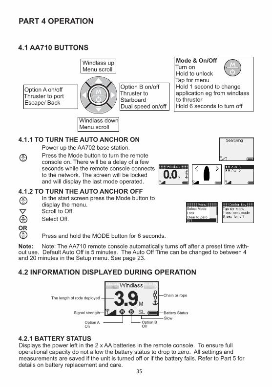
4.2.1 BATTERY STATUSDisplays the power left in the 2 x AA batteries in the remote console. To ensure full operational capacity do not allow the battery status to drop to zero. All settings and measurements are saved if the unit is turned off or if the battery fails. Refer to Part 5 for details on battery replacement and care.
4.2 INFORMATION DISPLAYED DURING OPERATION
The length of rode deployed Chain or rope
Battery StatusSignal strength
Option BOn
Option AOn
Option A on/offThruster to portEscape/ Back
Option B on/offThruster to StarboardDual speed on/off
Windlass downMenu scroll
Windlass upMenu scroll
4.1 AA710 BUTTONS
4.1.2 TO TURN THE AUTO ANCHOR OFF In the start screen press the Mode button to display the menu. Scroll to Off. Select Off.OR Press and hold the MODE button for 6 seconds.
Note: Note: The AA710 remote console automatically turns off after a preset time with-out use. Default Auto Off is 5 minutes. The Auto Off Time can be changed to between 4 and 20 minutes in the Setup menu. See page 23.
Mode & On/OffTurn onHold to unlockTap for menuHold 1 second to change application eg from windlass to thrusterHold 6 seconds to turn off
4.1.1 TO TURN THE AUTO ANCHOR ON Power up the AA702 base station. Press the Mode button to turn the remote console on. There will be a delay of a few seconds while the remote console connects to the network. The screen will be locked and will display the last mode operated.
Select ModeLockClear to Zero
Slow
PART 4 OPERATION
36
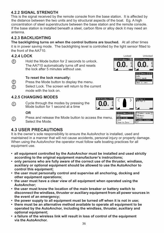
4.2.4 LOCK Hold the Mode button for 2 seconds to unlock.The AA710 automatically turns off and resetsthe lock after 5 minutes without use.
To reset the lock manually: Press the Mode button to display the menu.Select Lock. The screen will return to the current mode with the lock on.
UnlockedLocked
4.2.5 CHANGING MODESCycle through the modes by pressing the Mode button for 1 second at a time
Press and release the Mode button to access the menu. Select the Mode.
OR
Lock Clear to Zero
4.2.3 BACKLIGHTINGThe backlighting turns on when the control buttons are touched. At all other times it is in power saving mode. The backlighting level is controlled by the light sensor fitted to the front of the AA710.
4.2.2 SIGNAL STRENGTHThis is the signal received by the remote console from the base station. It is affected by the distance between the two units and by structural aspects of the boat. Eg. A high concentration of steel superstructure between the base station and the remote console. If the base station is installed beneath a steel, carbon fibre or alloy deck it may need an antenna.
4.3 USER PRECAUTIONSIt is the owner’s sole responsibility to ensure the AutoAnchor is installed, used and maintained in a manner that will not cause accidents, personal injury or property damage. When using the AutoAnchor the operator must follow safe boating practices for all equipment use.
• all equipment controlled by the AutoAnchor must be installed and used strictlyaccording to the original equipment manufacturer’s instructions;
• only persons who are fully aware of the correct use of the thruster, windlass,auxiliary or optional equipment should be allowed to use the AutoAnchor tocontrol this equipment;
• the user must personally control and supervise all anchoring, docking andother equipment operations;
• the user must have a clear view of all equipment when operated using theAutoAnchor;
• the user must know the location of the main breaker or battery switch todisconnect the windlass, thruster or auxiliary equipment from all power sources in the event of an emergency;
• the power supply to all equipment must be turned off when it is not in use;• there must be an alternative method available to operate all equipment to be
operated by the AutoAnchor, including the windlass, thruster, auxiliary andoptional equipment;
• a failure of the wireless link will result in loss of control of the equipmentvia the AutoAnchor.
37
4.4 SET UP AND TESTING Before use the AutoAnchor must be correctly set up for the equipment it is to control and then tested in a safe environment. For example, the AutoAnchor will not count correctly if the windlass selection is wrong or the windlass is not standard (eg it is installed with a different chainwheel or motor).
4.3.1 WHEN CONTROLLING A WINDLASS• maintain a clear view of the windlass, rode and/or anchor, plus any optional or auxiliary anchoring equipment during windlass operation;• always ensure the anchor is fully docked and secured before moving the boat.
4.3.2 WHEN CONTROLLING A THRUSTER• do not operate close to swimmers, the powerful suction of water could cause serious injury;• never run the thruster out of the water, this can cause serious damage to the motor;• running a thruster without resistance from the propeller can also cause serious damage to the motor;• if the thruster stops giving thrust while the motor is running, turn it off immediately.
The AutoAnchor manufacturer and supplier accept no liability for personal injury or property damage resulting from failure to follow the installation and operating instructions or the use of the AutoAnchor in a way that may cause accidents or damage or that may violate the law.
4.5 WINDLASS OPERATION WITH THE AA710
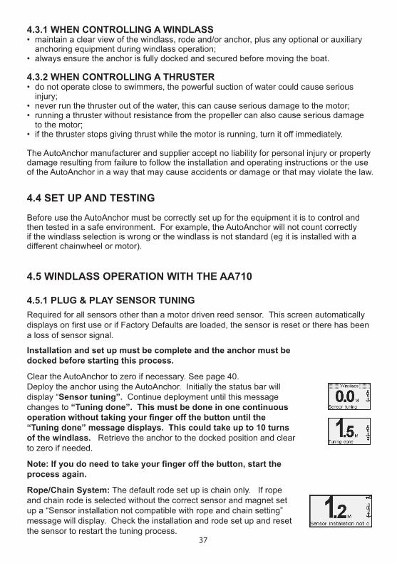
Installation and set up must be complete and the anchor must be docked before starting this process.
Clear the AutoAnchor to zero if necessary. See page 40. Deploy the anchor using the AutoAnchor. Initially the status bar will display “Sensor tuning”. Continue deployment until this message changes to “Tuning done”. This must be done in one continuous operation without taking your finger off the button until the “Tuning done” message displays. This could take up to 10 turns of the windlass. Retrieve the anchor to the docked position and clear to zero if needed.
Note: If you do need to take your finger off the button, start the process again.
Rope/Chain System: The default rode set up is chain only. If rope and chain rode is selected without the correct sensor and magnet set up a “Sensor installation not compatible with rope and chain setting” message will display. Check the installation and rode set up and reset the sensor to restart the tuning process.
Required for all sensors other than a motor driven reed sensor. This screen automatically displays on first use or if Factory Defaults are loaded, the sensor is reset or there has been a loss of sensor signal.
4.5.1 PLUG & PLAY SENSOR TUNING

38
Note: The AA710 remote console automatically turns off after a preset time without use. Default Auto Off is 5 minutes. The Auto Off Time can be changed from between 4 to 20 minutes in the Setup menu. See page 23.
For an accurate reading always ensure the AA710 display reads 0.0 before deploying the anchor. See Clear to Zero on page 40.
Counting continues if the AA710 remote console is turned off and if the windlass is operated by another control eg foot switches.
4.5.2 AUTOMATIC AND MANUAL WINDLASS OPERATIONKeep your finger on the button to deploy the anchor manually or use the automatic function for hands free anchor deployment and retrieval. See the instructions for both options below.
4.5.3 MANUAL WINDLASS OPERATION
Deploy and Retrieve the Anchor Using Manual Operation Turn the AA710 on. Clear the safety lock. Press and hold the up or down button to deploy or retrieve the anchor. Releasing the button stops the windlass operation. Ensure the anchor is fully docked and secured before moving the boat. DOCKING ALARM: During retrieval the windlass will stop and the AA710 beeps to warn the operator the anchor is at the preset docking distance. Press and hold the button to continue retrieval. If the system has been set up for dual speed. It will change to slow at this point. Extra care must be taken at this stage of retrieval.
Use the Automatic Function to:• Preset the length of rode for deployment;• Have hands-free operation of the windlass;• Retrieve the anchor automatically to the preset docking distance.
Note: For rope/chain counting, if the sensor or load sensing wires are not installed correctly the automatic function will not operate. An Installation warning message will display on the screen. The windlass can still be operated using manual operation but the AutoAnchor will not count accurately.
4.5.4 AUTOMATIC WINDLASS OPERATION WARNING: There is an inherent risk when using any automatic function on a boat. If you choose to use the AA710 automatic functions, you must still control and supervise all windlass and anchoring operation.
4.5.4.1 Safety Override
Press any button on the AA710 to stop the windlass during automatic release or retrieval. In an emergency shut off the power to the windlass using the isolating/breaker switch.
39
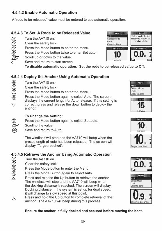
4.5.4.4 Deploy the Anchor Using Automatic Operation Turn the AA710 on. Clear the safety lock. Press the Mode button to enter the Menu. Press the Mode button again to select Auto. The screen displays the current length for Auto release. If this setting is correct, press and release the down button to deploy the anchor. To Change the Setting: Press the Mode button again to select Set auto. Scroll to the value. Save and return to Auto.
The windlass will stop and the AA710 will beep when the preset length of rode has been released. The screen will display “Target reached”.
4.5.4.3 To Set A Rode to be Released Value Turn the AA710 on. Clear the safety lock. Press the Mode button to enter the menu. Press the Mode button twice to enter Set auto. Scroll up or down to the value. Save and return to start screen. To disable automatic operation: Set the rode to be released value to Off.
4.5.4.2 Enable Automatic Operation
A “rode to be released” value must be entered to use automatic operation.
4.5.4.5 Retrieve the Anchor Using Automatic Operation Turn the AA710 on. Clear the safety lock. Press the Mode button to enter the Menu. Press the Mode Button again to select Auto. Press and release the Up button to retrieve the anchor. The windlass will stop and the AA710 will beep when the docking distance is reached. The screen will display Docking distance. If the system is set up for dual speed, it will change to slow speed at this point. Press and hold the Up button to complete retrieval of the anchor. The AA710 will beep during this process.
Select ModeLockClear to Zero
Select ModeLockClear to Zero
Select ModeLockClear to Zero
Ensure the anchor is fully docked and secured before moving the boat.

40
4.8.2 TO CHECK LOGS The AA710 must be turned on. Press to access the Menu. Scroll to Logs. Select Logs. Return to the menu. Exit and return to start screen. Logs can be cleared if base station is reset.
4.7 TO USE WINDLASS OPTION A AND OPTION B Use the Left arrow to turn Option A on and off. Use the Right arrow to turn Option B on and off. Note: If Auto wash is set it will turn on automatically during retrieval if any windlass control is used. Control could be via the AA710 and also foot switches, toggle switches or another AutoAnchor unit.
4.8 OTHER WINDLASS OPERATION SETTINGS Press to access the Menu when the AutoAnchor is turned on.
4.8.1 TO CLEAR TO ZEROThe AA710 must be turned on. Press to access the Menu. Scroll to Clear to Zero Select Clear to zero. Select No/Yes. Yes - return to start screen. No - return to the menu, then press again to return to the start screen.
4.6 USING DUAL SPEEDYou must have a windlass with a dual speed motor to use this feature. Default Speed is slow. Use the right arrow to toggle between fast and slow speed. The current speed is displayed on the screen SL or FS.If using Auto Mode select fast speed prior to selecting Auto.
The windlass automatically changes to slow speed when the docking distance is reached.
4.8.3 TO RESET SENSORThe AA710 must be turned on. Press to access the Menu. Select Reset sensor. Select No/Yes. Yes - return to start screen. No - return to the menu, then press again to return to the start screen. Deploy the anchor to tune the sensor. See page 37.
910742 112
LockClear to zeroOff
Select Mode

41
Use the left and right arrow buttons to control the thruster operation. Left to port and and right to starboard.
4.9 THRUSTER OPERATION WITH THE AA710The AA710 can control a single bow thruster or a bow and stern thruster together.
4.9.1 USER PRECAUTIONS
Note: The AA710 remote console automatically turns off after a preset time without use. Default Auto Off is 5 minutes. The Auto Off Time can be changed from between 4 to 20 minutes in the Setup menu. See page 23. If you have more than 1 console you must set the time for each console.
Only persons who are fully aware of the requirements for safe operation of the thruster should be allowed to use the AA710 to operate this equipment. The owner of the boat must take responsibility for ensuring the thruster is used according to the manufacturer’s instructions and with the appropriate safety precautions.
The thruster must not be operated close to swimmers, the powerful suction of water could cause serious injury. Never run the thruster out of the water as this can seriously damage the motor. Running a thruster without resistance from the propeller can also cause serious damage to the motor. If the thruster stops giving thrust while the motor is running, turn it off immediately. Always turn off the power to the thruster when it is not in use.
4.9.4 SINGLE BOW THRUSTER OPERATION
OR Access the Menu. Select “Select Mode”. Scroll to Thruster. Select Thruster.
4.9.2 TO ACCESS THE THRUSTER Turn the AutoAnchor on. Clear the safety lock. Cycle through the modes by pressing the Mode button for 1 second at a time
Thrust to port.
4.9.3 THRUSTER SYSTEM LOCKS
AA710 System locked. Hold Mode button to clear.
Local lock on. No access from AA710. Thruster operated by another controller.
Thrust to starboard.Bow thruster selected. System powered up and idle.

42
If there is a bow and a stern thruster fitted, use the up button to toggle between the bow thruster and the combined bow and stern thruster.
Use the down button to toggle between the stern thruster and the combined bow and stern thruster.
Use the left and right arrow buttons to control the thruster operation to port and starboard.
4.9.5 COMBINED BOW AND STERN THRUSTER OPERATION
Bow and stern thrusters selected. System powered up and idle.
Bow and stern thrusters to port.
Bow and stern thrusters to starboard.
Bow thruster selected. System powered up and idle.
Bow thrusting to port. Bow thrusting to starboard.
Stern thrusting to starboard. Stern thrusting to port. Stern thruster selected. System powered up and idle.
4.9.5.1 Dual Thruster Operation
4.9.5.2 Bow Thruster Operation
4.9.5.3 Stern Thruster Operation
43
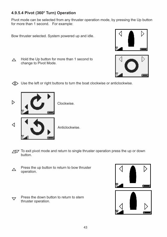
4.9.5.4 Pivot (360o Turn) Operation
Bow thruster selected. System powered up and idle.
Pivot mode can be selected from any thruster operation mode, by pressing the Up button for more than 1 second. For example:
Hold the Up button for more than 1 second to change to Pivot Mode.
Use the left or right buttons to turn the boat clockwise or anticlockwise.
To exit pivot mode and return to single thruster operation press the up or down button.
Press the up button to return to bow thruster operation.
Press the down button to return to stern thruster operation.
Clockwise.
Anticlockwise.

44
4.10 AUXILIARY EQUIPMENT OPERATION WITH THE AA710The AA710 can control other equipment on the boat such as pumps, davits or cleats usingthe auxiliary outputs.
4.10.1 USER PRECAUTIONSOnly persons who are fully aware of the requirements for safe operation of the auxiliary equipment should be allowed to use the AA710 to operate this equipment. The owner of the boat must take responsibility for ensuring the equipment is used according to the manufacturer’s instructions and with the appropriate safety precautions.
Note: The AA710 remote console automatically turns off after a preset time without use. Default Auto Off is 5 minutes. The Auto Off Time can be changed from between 4 to 20 minutes in the Setup menu. See page 23.
OR Tap to access the Menu. Scroll to “Select Mode”. Select “Select Mode”. Scroll to Auxiliary outputs. Select Auxiliary outputs.
On the console use the key shown on the screen to operate the Auxiliary output. The Auxiliary output will be highlighted on the screen when it is active.
M = MomentaryT = Toggle
4.10.2 TO ACCESS THE AUXILIARY MODE Turn the AA710 on. Clear the safety lock. Depending on the system set up. Cycle through the modes by pressing the button for 1 second at a time.
Auxiliary Key ReferencesAux A
Aux B
Aux C Aux D
45
PART 5 MAINTENANCEThe AutoAnchor does not contain any user servicable parts. User maintenance is limited to:• Checking all cables and connections for signs of wear or damage and replacing them as necessary.• Checking the sensor head is not worn and has not moved out of alignment with the magnet and replacing the sensor if necessary. After any sensor repairs or changes to sensor installation reset the sensor. See page 37. • Checking the magnet is not worn or corroded and replacing the magnet if necessary.
Note: Do not use chemical or abrasive materials to clean the console unit. If it is dirty wipe it with a clean damp cloth. Avoid wiping the display screen with a dry cloth as this could scratch the screen.
5.1 REPLACING THE BATTERY IN THE AA710 CONSOLE
Replace the batteries when the battery indicator shows the battery level is low. Do not allow the battery level to fall to zero. Two alkaline AA 1.5V batteries are required.
Turn off the console and turn off the power to the base station. Open the console case by removing the screws and lifting off the back cover.Remove the used batteries and replace them with new batteries in the same position. Check that the perimeter seal is clean and undamaged. Put the cover in place, refit the screws and tighten evenly. Do not overtighten the screws.
Battery Indicator
Battery Care
Insert batteries with the correct polarity. Replace both batteries at the same time. Do not mix old and new batteries or different types or brands of batteries.Remove exhausted batteries immediately from the device.Remove batteries and store separately if an extended period of non use is anticipated.Follow battery manufacturer’s instructions for disposal of used batteries.
Note: User settings are not affected by power loss or changing the batteries.
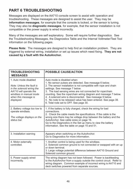
46
PART 6 TROUBLESHOOTINGMessages are displayed on the AA710 console screen to assist with operation and troubleshooting. These messages are designed to assist the user. They may be information messages, for example that the console is locked, or the sensor is tuning. They may also be diagnostic messages, for example, that the sensor installation is not compatible or the power supply is wired incorrectly.
Many of the messages are self explanatory. Some will require further diagnostics. See the Troubleshooting Messages, the Diagnostics Table and the Internal Voltmeter/Test Tool information on the following pages.
Please Note: The messages are designed to help find an installation problem. They are triggered by external wiring, installation or set up issues which need fixing. They are not caused by a fault with the AutoAnchor.
TROUBLESHOOTING MESSAGES
POSSIBLE CAUSE/ACTION
1. Auto mode disabled
Note: Unless the fault is in the solenoid wiring the AA710 will operate the windlass in manual mode when this message is displayed.
Auto mode is disabled when:1. No sensor pulses are detected. See message 6 below.2. The sensor installation is not compatible with rope and chainsettings. See message 7 below.3. The load sensing wires are not connected for rope/chaincounting. See the rope/chain wiring diagram and message 7 below.4. A solenoid wire is disconnected. See message 9 below.5. No rode to be released value has been entered. See page 39.6. Total rode set to OFF. See page 30.
2. Battery voltage too low tooperate windlass.
The voltage displays on the status bar.
1. If the battery is fully charged, check the wiring for badconnections. 2. Check the cable meets the specifications. If the cable is thewrong size there may be voltage drop between the battery and the AutoAnchor. See cable sizes on page 16.Go to the Diagnostics in the Set up menu to view the battery information. See the table on page 15 and 51.
3. Installation warning Appears when switching on the AutoAnchor. Go to Diagnostics for more information.
4. Motor externallycontrolled.
1. Another control is being used for the windlass.2. Solenoid common ground is not connected or swapped with an upor down terminal.3. Large voltage potential difference between AA710 Ground andSolenoid common ground.
5. Power supply wiredincorrrectly.
The wiring diagram has not been followed. Power is backfeeding to the AutoAnchor from a supply outside the control circuit. Refer to wiring diagram. Common example of incorrect wiring is AA710 and deck switches powered from separate sources.
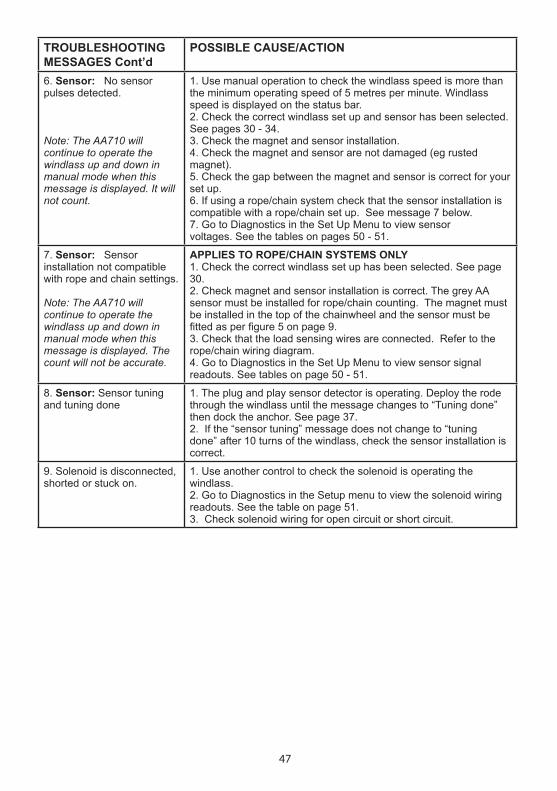
47
TROUBLESHOOTING MESSAGES Cont’d
POSSIBLE CAUSE/ACTION
6. Sensor: No sensorpulses detected.
Note: The AA710 will continue to operate the windlass up and down in manual mode when this message is displayed. It will not count.
1. Use manual operation to check the windlass speed is more thanthe minimum operating speed of 5 metres per minute. Windlass speed is displayed on the status bar. 2. Check the correct windlass set up and sensor has been selected.See pages 30 - 34. 3. Check the magnet and sensor installation.4. Check the magnet and sensor are not damaged (eg rustedmagnet).5. Check the gap between the magnet and sensor is correct for yourset up.6. If using a rope/chain system check that the sensor installation iscompatible with a rope/chain set up. See message 7 below.7. Go to Diagnostics in the Set Up Menu to view sensorvoltages. See the tables on pages 50 - 51.
7. Sensor: Sensorinstallation not compatible with rope and chain settings.
Note: The AA710 will continue to operate the windlass up and down in manual mode when this message is displayed. The count will not be accurate.
APPLIES TO ROPE/CHAIN SYSTEMS ONLY 1. Check the correct windlass set up has been selected. See page30. 2. Check magnet and sensor installation is correct. The grey AA sensor must be installed for rope/chain counting. The magnet must be installed in the top of the chainwheel and the sensor must be fitted as per figure 5 on page 9.3. Check that the load sensing wires are connected. Refer to therope/chain wiring diagram.4. Go to Diagnostics in the Set Up Menu to view sensor signalreadouts. See tables on page 50 - 51.
8. Sensor: Sensor tuningand tuning done
1. The plug and play sensor detector is operating. Deploy the rodethrough the windlass until the message changes to “Tuning done” then dock the anchor. See page 37. 2. If the “sensor tuning” message does not change to “tuningdone” after 10 turns of the windlass, check the sensor installation is correct.
9. Solenoid is disconnected,shorted or stuck on.
1. Use another control to check the solenoid is operating thewindlass. 2. Go to Diagnostics in the Setup menu to view the solenoid wiringreadouts. See the table on page 51. 3. Check solenoid wiring for open circuit or short circuit.

48
WIRELESS NETWORK TROUBLESHOOTING
POSSIBLE CAUSE/ACTION
1. Screen Message: Cannot register console and base stations.
1. Turn all consoles and base stations off and then back on. Try registration again. If the problem persists:2. Clear registration for all consoles and base stations (see page 18). Try registration again. If the problem persists:3. Units may be out of range. Try repositioning the console or base station before trying registration again.4. Check if the base station or console is close to severe interference eg. VHF radios, modified sine wave inverters, cable and antennas or radar antennas.5. If connection is still not possible the system may require an antenna (Part #9403).
2. Console cannot find base station. Console displays ‘‘base not found’ for 60 seconds and then it will turn off.
1. Check that master base station is powered up. If the problem persists:2. There may be interference on the current channel. Turn all consoles and base stations off and then back on. If the problem persists:3. Units may be out of range. Try repositioning the console or base station. If the problem persists:4. The registration may be incorrect. Clear registration settings for all consoles and base stations (see page 18). Try registration again.Check if the base station or console is close to severe interference eg. VHF radios, modified sine ware inverters, cable and antennas or radar antennas.5. Try setting to another channel. See page 23.6. If connection is still not possible the system may require an antenna. (Part #9403).
3. Console will not turn on. 1. Check batteries are installed correctly. Batteries may require replacing.
4. System works in one location but will not connect at another or will not work at different times of the day.
1. There may be interference on the transmission channel. See Section 3.4.5, page 23 to set the system to another channel. 2. The system may require an antenna (Part #9403).
5. Immediately after pressing a button the solenoids click on and then off. Then the console loses connection
1. The power supply has dropped below 5V causing the unit to reset. To test check the base station. All 3 x LED’s will flash twice before shutting down the system.2. Check the battery voltage. 3. Check power supply wiring. It is likely the cable is below specification causing voltage drop.

49
AFTER ANY SENSOR REPAIRS OR CHANGES:DOCK THE ANCHOR AND RESET THE SENSOR. SEE PAGE 37.
OTHER TROUBLESHOOTING POSSIBLE CAUSE/ACTION1. AutoAnchor counts when the windlass is not turning or counts erratically displaying a large number. The screen may display Sensor unstable and the unit may beep when turned off or locked.
1. Uncontrolled anchor rode could be running through the windlass or there may be some external interference. 2. The sensor may be damaged. The sensor cable is not the specified type or the connection may be faulty. 3. Check the sensor wiring. If the AA sensor plug is not used the wires must be soldered. All wires must be connected (including the drain) and shielded cable must be used.
3. AutoAnchor counts but does not operate the windlass
Total length of rode has been set to off. AutoAnchor then operates as a counter only. See page 39.
4. The count pauses during retrieval.
This applies to rope/chain rode only.
If the sensor indicator (arrow) is still pulsing, this is not a fault. The rode is changing from rope to chain.
5. The count stays on zero when rode is deployed and counts out when rode is retrieved.
The unit is not receiving correct direction information. Solenoid up and down wires are swapped.
6. Windlass deploys when the Up button is pressed and retrieves when the Down button is pressed.
1. The motor or solenoid wiring is reversed. Change the wiring and check the direction of windlass rotation. If the brown and white wires are connected, also check that they are correct after you have changed the wiring.2. Buttons are swapped in the windlass menu. See page 34.
7. Windlass does not stop exactly at the preset point.
Stopping is accurate to +1 chainwheel revolution. The chainwheel will run on slightly with momentum.
8. Windlass stops before the length of rode specified is deployed.
Using the Automatic function the rode release stops 10ft (3m) short of the Total Length of Rode on Board setting.
FOR ADDITIONAL TROUBLESHOOTING:Contact AutoAnchor support on:www.autoanchor.co.nz/autoanchor-installation-help.php Fill in the information form.Email: [email protected] or Telephone: +64 9 360 0300

50
Access the information from the Set up menu or from the installation warning screen.
Diagnostic messages help find an installation problem. The diagnostic messages are all caused by external wiring, set up or installation issues which need fixing. They are not caused by a fault with the AutoAnchor.
INTERNAL VOLTMETER/TEST TOOL: This tool displays the voltages and status of sensor, battery and load wires. The information is required by the AutoAnchor support team for effective technical assistance.
Contact AutoAnchor support on:www.autoanchor.co.nz/autoanchor-installation-help Fill in the information form.or Email: [email protected] or Telephone: +64 9 360 0300.
Press again for extended diagnostic information and test tools.
PART 7 TECHNICIAN DIAGNOSTIC INFORMATION
Use to scroll through the menus and to select Diagnostics.
Hold together to display the Set up menu.The AA710 must be turned off to access the Set up menu.
Correct Parameters
AA Grey SensorChain Only Set UpBottom Fit Magnet Polarity not relevant
Signal A - (Red sensor wire from the console) is sensor power supply. Voltage must be between 4.6V and 4.9V.Signal B - Reading depends on gap and magnet polarity. Range 0.5V - 4.6V. Minimum working signal 0.5V.Signal C - If Signal B is less than 0.5V then Signal C will take over and operate down to 100mV for an all chain set up.
AA Grey Sensor Rope/Chain Set Up Top Fit MagnetPolarity not relevant
Signal A - (Red sensor wire from the console) is sensor power supply.Signal B - Reading is not relevant.Signal C - Minimum value is 100 mV when reading the chain pulses.
AA Black SensorChain Only Set UpBottom Fit MagnetSouth pole must face sensor
Signal A - (Red sensor wire from the console) moves between 2.6V and 4.6V. Minimum working signal 0.5V.Signal B - Reading is not relevantSignal C - Reading is not relevant.
Reed SwitchChain Only Set UpBottom Fit MagnetPolarity not relevant
Signal A - (Red sensor wire from the console) is not used. Black sensor wire (from the console) is connected to the reed switch.Signal B - Range is 0.0V to 5V.Signal C - Reading is not relevant.
NPN Proximity Sensor Chain Only Set Up
Signal A - (Red sensor wire from the console) is the proximity sensor’s power supply.Signal B - Range 2.5V - 4.6V. Minimum working signal 0.5V Signal C - Reading is not relevant.
Sensor
Sou
rce
Icon
Sig
nal
Volta
ge (V
)
Sign
al (m
V)
To update the recorded signal levels rotate the windlass 2 or more turns Press buttons or freewheel the windlass to rotate. Check the windlass is safe and clear before using this function.
Sensor Information
Tuning done Signal A 4.6 0.0 Signal B 2.5 0.5 Signal C -166 501
Sensor
Tuning done Signal A 4.6 1.2 Signal B 5.0 0.0 Signal C -166 501
Sensor
Tuning done Signal A 5.0 0.0 Signal B 0.0 5.0 Signal C -166 501
Sensor
Tuning done Signal A 4.3 0.0
Signal C -166 501
Sensor
Tuning done Signal A 4.6 0.0 Signal B 2.5 0.5 Signal C -166 501
Sensor
Tuning done Signal A 4.6 0.0 Signal B 2.5 0.5 Signal C -166 501
Sensor
Signal B 0.5 3.53.5 2.2

51
Other Diagnostic Messages Possible Causes and SolutionsCheck the solenoid wires are properly connected.Solenoid common ground is not connected or swapped with an up or down terminal.The load connected to the solenoid wires is insufficient. Check that each solenoid wire has a load of more than 10mA (12V DC) or 20mA (24V DC).The idle voltage is greater than 2.0V - this can occur when connecting to a solid state or low current drive windlass control eg PLC or AC VFD. A dummy resistor load Part #9515 may be required to fix this.
These wires are used for combination rope and chain rodes. They are not required for chain only use.When correctly connected to the motor teminal both wires show nearly zero volts at idle. Under load they show motor ground and supply terminal voltages.
The voltage at the time of failure is recorded on the status bar.
This page records the voltage drop when the motor is started. In this example the supply voltage to the AA710 fell below 6V for a short period.The power supply wiring has high resistance or is too thin for the distance of the run or the ground wire is disconnected.
Battery
Load wires
Down Solenoid
Up Solenoid
10.7 V
5.6 V
Sensor Installation Diagnostic MessagesThese messages appear when the AA710 is turned on. Go to the extended diagnostics for moreinformation. After fixing the sensor installation retune the sensor. See page 37. Red sensor wire grounded
The Red sensor wire is overloaded below 2.5 voltsDisconnect the plugs one at a time to locate the short or excessive load.If no short is found, the sensor may be damaged. Try a new sensor. Windlass will operate but not count.
No Sensor pulses Electrical connections are OK (voltages are correct) but no sensor pulses are being received by the console and it is not counting.Rotate the windlass to check for signal voltage. If there is still no signal either the magnet or the sensor needs replacing. Check the magnet is strong and not rusted and check the sensor for physical damage.
Sensor installation not compatible with rope and chain settings.
A rope/chain rode has been selected but the installation is not compatible with this selection. The system is tuned to the Signal B sensor input (all chain) instead of Signal C sensor input (rope/chain). Possible causes: Magnet is installed on the bottom of chainwheel instead of the top.The sensor is not the grey AA sensor.The windlass has been operated with no chain so the tuning is incorrect.
Orange wiredisconected
Yellow wiredisconected
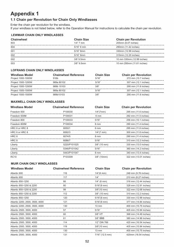
Enter the chain per revolution for the windlass. If your windlass is not listed below, refer to the Operation Manual for instructions to calculate the chain per revolution.
maxwell Chain Only windlasses
appendix 11.1 Chain per Revolution for Chain Only windlasses
muiR Chain Only windlasses
lewmaR Chain Only windlasses
603 1/4” 7 mm 205mm (8.07 inches)
604 5/16” 8 mm 290mm (11.42 inches)
001 5/16” 8mm 330mm (12.99 inches)
002 5/16” 8mm 310mm (12.20 inches)
002 3/8’ 9.5mm 10 mm 330mm (12.99 inches)
003 3/8” 9.5mm 10 mm 295mm (11.61 inches)
Chainwheel Chain size Chain per Revolution
lOfRans Chain Only windlasses
Project 1000-1000W 916b 5/16” 272 mm (10.7 inches)
Project 1500-1200W 989a 80102 5/16” 307 mm (12.1 inches)
Project 1500-1200W 989b 10103 3/8” 295 mm (11.6 inches)
Project 1500-1500W 989a 80102 5/16” 307 mm (12.1 inches)
Project 1500-1500W 989b10103 3/8” 295 mm (11.6 inches)
windlass model Chainwheel Reference Chain size Chain per Revolution
Freedom 500 P100030 1/4”(7mm) 295 mm (11.6 inches)
Freedom 500M P100031 6 mm 292 mm (11.5 inches)
Freedom 800 P100033 5/16” 256 mm (10.1 inches)
Freedom 800M P100034 8 mm 290 mm (11.4 inches)
HRC 6 or HRC 8 6050/1 6 mm 295 mm (11.6 inches)
HRC 6 or HRC 8 6062/3 1/4”(7 mm) 300 mm (11.8 inches)
HRC 8 6074/5 8 mm 290 mm (11.4 inches)
HRC 8 6086/7 5/16” 310 mm (12.2 inches)
Liberty 5220/P101525 3/8” (10 mm) 330 mm (13.0 inches)
Liberty 5346/P101542 5/16” 360 mm (14.2 inches)
Liberty 5443/P101547 8 mm 340 mm (13.4 inches)
RC10 P103309 3/8” (10mm) 322 mm (13.01 inches)
windlass model Chainwheel Reference Chain size Chain per Revolution
Atlantic 600 116 1/4”(6 mm) 248 mm (9.76 inches)
Atlantic 600 117 1/4” 210 mm (8.27 inches)
Atlantic 850-1250 66 1/4” (6 mm) 316 mm (12.44 inches)
Atlantic 850-1250 & 2200 80 5/16”(8 mm) 328 mm (12.91 inches)
Atlantic 850-1250 & 2200 99 3/8”(10 mm) 322 mm (12.68 inches)
Atlantic 850-1250 & 2200 112 3/8” (10 mm) 310 mm (12.2 inches)
Atlantic 850-1250 120 5/16”(8 mm) 330 mm (12.99 inches)
Atlantic 2200, 2500, 3500, 4000 121 5/16”(8 mm) 377 mm (14.84 inches)
Atlantic 2200, 2500, 3500, 4000 130 13 mm 400 mm (15.75 inches)
Atlantic 2500, 3500, 4000 57 5/16” 405 mm (15.94 inches)
Atlantic 2500, 3500, 4000 60 3/8” HT 368 mm (14.49 inches)
Atlantic 2500, 3500, 4000 61 3/8” BBB 380 mm (14.96 inches)
Atlantic 2500, 3500, 4000 114 1/2” DIN 766 420 mm (16.54 inches)
Atlantic 2500, 3500, 4000 119 3/8”(10 mm) 405 mm (15.94 inches)
Atlantic 2500, 3500, 4000 130 13 mm 400 mm (15.75 inches)
Atlantic 2500, 3500, 4000 131 7/16” (12.5 mm) 420mm (16.54 inches)
windlass model Chainwheel Reference Chain size Chain per Revolution
52

lewmaR ROPe & Chain windlasses
1.2 Pre-set Windlass Profile List for Rope & Chain WindlassesFind the windlass model.Check the chainwheel reference.Check the chain size.Check the rope size.Select the AutoAnchor reference number.
If your windlass is not on the list, you need to calculate the length of chain and rope that is released during one complete revoution of the chainwheel. See Operation Manual for instructions.
lOfRans ROPe & Chain windlasses
9960 0910
windlass motor Volts Chainwheel Chain size Rope size autoanchor Reference 3 strand Reference
Lewmar Sprint 600 250W 12 603 1/4” 7mm 1/2” 12mm 128
Lewmar Sprint 1000 400W 12 604 5/16” 8mm 9/16”14mm 129
Lewmar V2 700W 12 001 5/16” 8 mm 9/16” 14mm 123
Lewmar V2 700W 12 001 5/16” 8mm 5/8” 16mm 122
Lewmar V2 700W 12 002 3/8” 9.5mm 9/16” 14mm 119
Lewmar V2 700W 12 002 3/8” 9.5mm 5/8” 16mm 118
Lewmar V2 700W 12 002 5/16” 8mm 9/16” 14mm 114
Lewmar V2 700W 12 002 5/16” 8mm 5/8” 16mm 113
Lewmar V2 1000W 12 003 3/8” 9.5mm 5/8” 16mm 120
Lewmar V3 1000W 12 002 5/16” 8mm 5/8” 16mm 116
Lewmar V3 1000W 12 001 5/16” 8 mm 5/8” 16 mm 126
Lewmar V3 1000W 12 001 5/16” 8 mm 9/16” 14mm 127
Lewmar V3 1000W 12 002 3/8” 9.5mm 9/16” 14mm 124
Lewmar V3 1000W 12 002 5/16” 8 mm 9/16” 14mm 117
Lewmar V700 320W 12 765 + 670 1/4” 7mm 1/2” 12mm 130
Lewmar V700 320W 12 670 1/4” 6mm 1/2” 12mm 130
Lewmar Pro-Series 700 500W 12 762 1/4” 7mm 5/8” 16mm 131
windlass model Chainwheel Chain size Rope size autoanchor ReferenceDorado 7mm 14mm 65
Dorado 7mm 12 mm 66
Project 1000-1000W 916b 5/16” 5/8” (16mm) 3 strand 61
Project 1000-1000W 916b 5/16” 5/8” (16 mm) 8 plait 62
Project 1000-1000W 916b 5/16” 9/16” (14 mm) 3 strand 63
Project 1000-1000W 916b 5/16” 9/16” (14 mm) 8 plait 64
Project 1500-1200W 989a 80102 5/16” 5/8” (16 mm) 3 strand 55
Project 1500-1200W 989a 80102 5/16” 5/8” (16 mm) 8 plait 56
Project 1500-1200W 989b 10103 3/8” (10 mm) 3/4” (20 mm) 3 strand 57
Project 1500-1200W 989b 10103 3/8” (10 mm) 3/4” (20 mm) 8 plait 58
Project 1500-1200W 989b 10103 3/8” (10 mm) 5/8” (16 mm) 3 strand 59
Project 1500-1200W 989b 10103 3/8” (10 mm) 5/8” (16 mm) 8 plait 60
Project 1500-1500W 989a 80102 5/16” 5/8” (16 mm) 3 strand 49
Project 1500-1500W 989a 80102 5/16” 5/8” (16 mm) 8 plait 50
Project 1500-1500W 989b10103 3/8” (10 mm) 5/8” (16 mm) 3 strand 47
Project 1500-1500W 989b10103 3/8” (10 mm) 5/8” (16 mm) 8 plait 48
Project 1500-1500W 989b10103 3/8” (10 mm) 3/4” (20 mm) 3 strand 46
Project 1500-1500W 989b10103 3/8” (10 mm) 3/4” (20 mm) 8 plait 45
53

maxwell ROPe & Chain windlasses
windlass model Chainwheel Chain size Rope size autoanchor Reference Reference
Freedom 500 P100030 ¼” (7 mm) ½” (12 mm) 3 strand 35
Freedom 500 P100030 ¼” (7 mm) ½” (12 mm) 8 plait 34
Freedom 500-1000W P100030 ¼” (7 mm) ½” (12 mm) 3 strand 21
Freedom 500M P100031 6 mm ½” (12 mm) 3 strand 2
Freedom 500M P100031 6 mm ½” (12 mm) 8 plait 33
Freedom 500M-1000W P100031 6 mm ½” (12 mm) 3 strand 22
Freedom 800 P100033 5/16” 5/8” (16 mm) 3 strand 40
Freedom 800 P100033 5/16” 5/8” (16 mm) 8 plait 39
Freedom 800 P100033 5/16” ½” (12 mm) 3 strand 36
Freedom 800 P100033 5/16” ½” (12 mm) 8 plait 37
Freedom 800 P100033 5/16” 9/16” (14 mm) 3 strand 38
Freedom 800M P100034 8 mm 9/16” (14 mm) 3 strand 1
Freedom 800M P100034 8 mm ½” (12 mm) 3 strand 41
Freedom 800M P100034 8 mm ½” (12 mm) 8 plait 42
HRC 6 6050/1 6 mm ½” (12 mm) 3 strand or 8 plait 23
HRC 6 6062/3 ¼” (7mm) ½” (12 mm) 8 strand or 8 plait 24
HRC 8 6050/1 6 mm ½” (12 mm) 3 strand or 8 plait 25
HRC 8 6062/3 ¼” (7 mm) ½” (12 mm) 3 strand or 8 plait 26
HRC 8 6074/5 8 mm 9/16” (14 mm) 3 strand or 8 plait 27
HRC 8 6074/5 8 mm 5/8” (16 mm) 3 strand or 8 plait 28
HRC 8 6086/7 5/16” ½” (12 mm) 3 strand 29
HRC 8 6086/7 5/16” ½” (12 mm) 8 plait 30
HRC 8 6086/7 5/16” 9/16” (14 mm) 3 strand 31
HRC 8 6086/7 5/16” 5/8” (16 mm) 3 strand 32
Liberty - 1000 Watt 5220/P101525 3/8” (10 mm) ¾” (20 mm) 3 strand 7
Liberty - 1000 Watt 5220/P101525 3/8” (10 mm) ¾” (20 mm) 8 plait 8
Liberty - 1000 Watt 5346/P101542 5/16” 5/8” (16 mm) 3 strand 5
Liberty - 1000 Watt 5346/P101542 5/16” 5/8” (16 mm) 8 plait 6
Liberty - 1000 Watt 5443/P101547 8 mm 5/8” (16 mm) 3 strand 3
Liberty - 1000 Watt 5443/P101547 8 mm 5/8” (16 mm) 8 plait 4
Liberty - 1200 Watt 5220/P101525 3/8” (10 mm) ¾” (20 mm) 3 strand 13
Liberty - 1200 Watt 5220/P101525 3/8” (10 mm) ¾” (20 mm) 8 plait 14
Liberty - 1200 Watt 5346/P101542 5/16” 5/8” (16 mm) 3 strand 11
Liberty - 1200 Watt 5346/P101542 5/16” 5/8” (16 mm) 8 plait 12
Liberty - 1200 Watt 5443/P101547 8 mm 5/8” (16 mm) 3 strand 9
Liberty - 1200 Watt 5443/P101547 8 mm 5/8” (16 mm) 8 plait 10
Liberty - 1500 Watt 5220/P101525 3/8” (10 mm) ¾” (20 mm) 3 strand 19
Liberty - 1500 Watt 5220/P101525 3/8” (10 mm) ¾” (20 mm) 8 plait 20
Liberty - 1500 Watt 5346/P101542 5/16” 5/8” (16 mm) 3 strand 17
Liberty - 1500 Watt 5346/P101542 5/16” 5/8” (16 mm) 8 plait 18
Liberty - 1500 Watt 5443/P101547 8 mm 5/8” (16 mm) 3 strand 15
Liberty - 1500 Watt 5443/P101547 8 mm 5/8” (16 mm) 8 plait 16
RC10 P103309 3/8” (10mm) 5/8” (16 mm) 3 strand 43
54
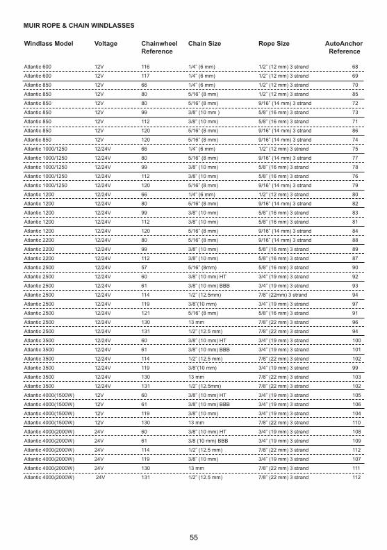
muiR ROPe & Chain windlasses
windlass model Voltage Chainwheel Chain size Rope size autoanchor Reference Reference
Atlantic 600 12V 116 1/4” (6 mm) 1/2” (12 mm) 3 strand 68
Atlantic 600 12V 117 1/4” (6 mm) 1/2” (12 mm) 3 strand 69
Atlantic 850 12V 66 1/4” (6 mm) 1/2” (12 mm) 3 strand 70
Atlantic 850 12V 80 5/16” (8 mm) 1/2” (12 mm) 3 strand 85
Atlantic 850 12V 80 5/16” (8 mm) 9/16” (14 mm) 3 strand 72
Atlantic 850 12V 99 3/8” (10 mm ) 5/8” (16 mm) 3 strand 73
Atlantic 850 12V 112 3/8” (10 mm) 5/8” (16 mm) 3 strand 71
Atlantic 850 12V 120 5/16” (8 mm) 9/16” (14 mm) 3 strand 86
Atlantic 850 12V 120 5/16” (8 mm) 9/16” (14 mm) 3 strand 74
Atlantic 1000/1250 12/24V 66 1/4” (6 mm) 1/2” (12 mm) 3 strand 75
Atlantic 1000/1250 12/24V 80 5/16” (8 mm) 9/16” (14 mm) 3 strand 77
Atlantic 1000/1250 12/24V 99 3/8” (10 mm) 5/8” (16 mm) 3 strand 78
Atlantic 1000/1250 12/24V 112 3/8” (10 mm) 5/8” (16 mm) 3 strand 76
Atlantic 1000/1250 12/24V 120 5/16” (8 mm) 9/16” (14 mm) 3 strand 79
Atlantic 1200 12/24V 66 1/4” (6 mm) 1/2” (12 mm) 3 strand 80
Atlantic 1200 12/24V 80 5/16” (8 mm) 9/16” (14 mm) 3 strand 82
Atlantic 1200 12/24V 99 3/8” (10 mm) 5/8” (16 mm) 3 strand 83
Atlantic 1200 12/24V 112 3/8” (10 mm) 5/8” (16 mm) 3 strand 81
Atlantic 1200 12/24V 120 5/16” (8 mm) 9/16” (14 mm) 3 strand 84
Atlantic 2200 12/24V 80 5/16” (8 mm) 9/16” (14 mm) 3 strand 88
Atlantic 2200 12/24V 99 3/8” (10 mm) 5/8” (16 mm) 3 strand 89
Atlantic 2200 12/24V 112 3/8” (10 mm) 5/8” (16 mm) 3 strand 87
Atlantic 2500 12/24V 57 5/16” (8mm) 5/8” (16 mm) 3 strand 90
Atlantic 2500 12/24V 60 3/8” (10 mm) HT 3/4” (19 mm) 3 strand 92
Atlantic 2500 12/24V 61 3/8” (10 mm) BBB 3/4” (19 mm) 3 strand 93
Atlantic 2500 12/24V 114 1/2” (12.5mm) 7/8” (22mm) 3 strand 94
Atlantic 2500 12/24V 119 3/8”(10 mm) 3/4” (19 mm) 3 strand 97
Atlantic 2500 12/24V 121 5/16” (8 mm) 5/8” (16 mm) 3 strand 91
Atlantic 2500 12/24V 130 13 mm 7/8” (22 mm) 3 strand 96
Atlantic 2500 12/24V 131 1/2” (12.5 mm) 7/8” (22 mm) 3 strand 94
Atlantic 3500 12/24V 60 3/8” (10 mm) HT 3/4” (19 mm) 3 strand 100
Atlantic 3500 12/24V 61 3/8” (10 mm) BBB 3/4” (19 mm) 3 strand 101
Atlantic 3500 12/24V 114 1/2” (12.5 mm) 7/8” (22 mm) 3 strand 102
Atlantic 3500 12/24V 119 3/8”(10 mm) 3/4” (19 mm) 3 strand 99
Atlantic 3500 12/24V 130 13 mm 7/8” (22 mm) 3 strand 103
Atlantic 3500 12/24V 131 1/2” (12.5mm) 7/8” (22 mm) 3 strand 102
Atlantic 4000(1500W) 12V 60 3/8” (10 mm) HT 3/4” (19 mm) 3 strand 105
Atlantic 4000(1500W) 12V 61 3/8” (10 mm) BBB 3/4” (19 mm) 3 strand 106
Atlantic 4000(1500W) 12V 119 3/8” (10 mm) 3/4” (19 mm) 3 strand 104
Atlantic 4000(1500W) 12V 130 13 mm 7/8” (22 mm) 3 strand 110
Atlantic 4000(2000W) 24V 60 3/8” (10 mm) HT 3/4” (19 mm) 3 strand 108
Atlantic 4000(2000W) 24V 61 3/8 (10 mm) BBB 3/4” (19 mm) 3 strand 109
Atlantic 4000(2000W) 24V 114 1/2” (12.5 mm) 7/8” (22 mm) 3 strand 112
Atlantic 4000(2000W) 24V 119 3/8” (10 mm) 3/4” (19 mm) 3 strand 107
Atlantic 4000(2000W) 24V 130 13 mm 7/8” (22 mm) 3 strand 111
Atlantic 4000(2000W) 24V 131 1/2” (12.5 mm) 7/8” (22 mm) 3 strand 112
55
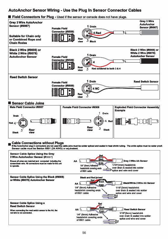
9067
56

The
c
an a
lso b
e c
onnect
ed d
irect
ly in
to a
ny
12v
or
24v
pro
tect
ed p
ow
er
supply
*
AA
570
*
702/7
03 B
AS
E S
TA
TIO
N S
YS
TE
MS
RE
FE
R T
O
SE
CT
ION
2.4
.1
57

*
The
c
an a
lso b
e c
onnect
ed d
irect
ly in
to a
ny
12v
or
24v
pro
tect
ed p
ow
er
supply
*
AA
570
702/7
03 B
AS
E S
TA
TIO
N S
YS
TE
MS
RE
FE
R T
O
SE
CT
ION
2.4
.1
58

The
c
an a
lso b
e c
onnect
ed d
irect
ly in
to a
ny
12v
or
24v
pro
tect
ed p
ow
er
supply
*
AA
570
*
RE
FE
R T
O
SE
CT
ION
2.4
.1
702/7
03 B
AS
E S
TA
TIO
N S
YS
TE
MS
59

AA702A.4: EXAMPLE THRUSTER WITH WINDLASS WIRING FOR AA710 | 730 SYSTEM
WARNING:Power must be disconnected during installation and when making any changes to wiring after installation.
IMPORTANT NOTES:1. Refer to thruster manufacturers' specifications for fuse/breakerand isolator requirements.2. Refer to thruster manufacturers' specifications for main powercable specifications.3. An additional isolating switch should be installed for controls if themain breaker or isolator is not readily accessible from the helm.4. If thruster control circuit uses negative switching, connect a relay between the AA702A output and the control wire to convert from positiveto negative switching. 5. Base Station must be positioned to allow internal access during and after installation.6. Stern and Bow output locations stated are the default locations.These can be swapped in the AA710-6 system setup menu.7. There must be an alternative method available to operate the windlass, thruster or other equipment.A failure of the wireless link will result in loss of control of the equipment via the AA710-6. 8. Installations must be carried out in accordance with USCG, ABYC,NMMA and BMEA requirements.
AA702A Base StationInternal Connections
Other Control / Panel
Control Circuit Terminals
(Positive Switching)
BATT (-)
COM (+)
PORT (+)
STBD (+)
BATT (-)
COM (+)
PORT (+)
STBD (+)
Other Control / Panel
BOWTHRUSTER
STERNTHRUSTER
WINDLASS SYSTEM
Refer to windlass wiring diagrams
AA702TERM
Default FunctionAssignment
BATT (-) Ground
BATT (+) Positive
OUT 1 (+) WindlassDown
OUT 2 (+) Windlass Up
OUT 3 (+) Thruster A (Bow) Port
OUT 4 (+) Thruster A (Bow) Starboard
OUT 5White
(+) Thruster B (Stern) Port
OUT 6Brown
(+) Thruster B (Stern) Starboard
AA702A Base Station Internal Connections Other Control / Panel
Control Circuit Terminals
(Positive Switching)
BATT (-)
COM (+)
PORT (+)
STBD (+)
BATT (-)
COM (+)
PORT (+)
STBD (+)
Other Control / Panel
BOWTHRUSTER
STERNTHRUSTER
AA702TERM
Default FunctionAssignment
BATT (-) Ground
BATT (+) Positive
OUT 1 (+) WindlassDown
OUT 2 (+) Windlass Up
OUT 3 (+) Thruster A (Bow) Port
OUT 4 (+) Thruster A (Bow) Starboard
OUT 5White
(+) Thruster B (Stern) Port
OUT 6Brown
(+) Thruster B (Stern) Starboard
Alternative Function
Power Enable when dual thrusters selected
Notes:
See owners manual section for more detailsAll outputs are active high (+) at battery level. If the product control system does not operate at this level relays must be used to isolate the 702A and the controlled product
Notes:
See owners manual section for more detailsAll outputs are active high (+) at battery level. If the product control system does not operate at this level relays must be used to isolate the 702A and the controlled product
Windlass and Two thrusters
Two thrusters with power enablePower enable for Hydraulic, AC, DC power pack or PLC controllerTimes out after 0- 60 Minutes
Thruster enable
Thruster enable
60
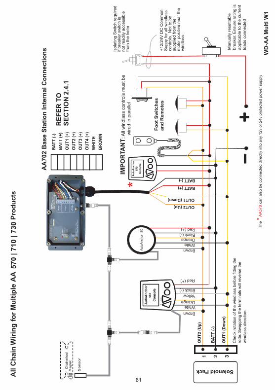
*
The
c
an a
lso b
e c
onnect
ed d
irect
ly in
to a
ny
12v
or
24v
pro
tect
ed p
ow
er
supply
*
AA
570
57
0 |
71
0 |
73
0
WD
-AA
Mu
lti W
1
RE
FE
R T
O
SE
CT
ION
2.4
.1
61
56
0
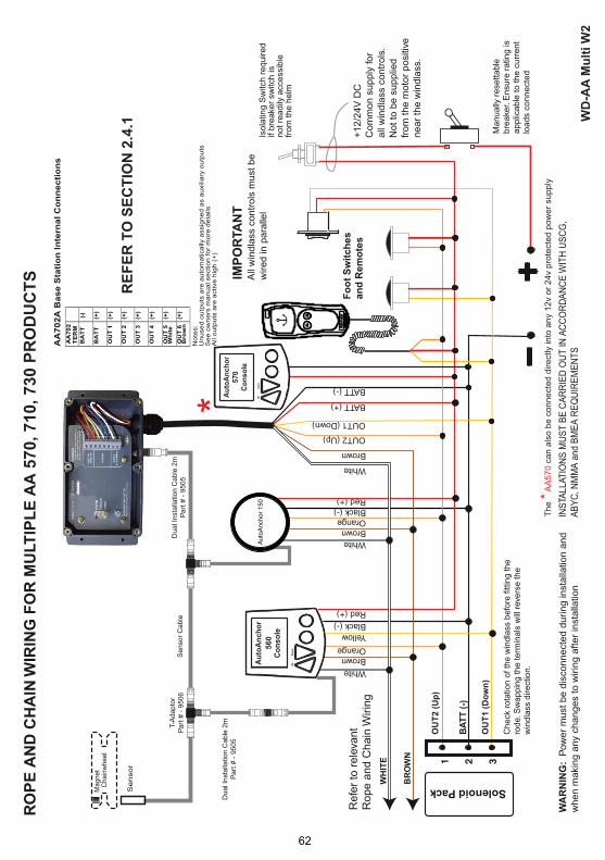
570, 710, 730 P
RO
DU
CT
S
RE
FE
R T
O S
EC
TIO
N 2
.4.1 W
D-A
A M
ult
i W
2
56
0
*
The
c
an a
lso b
e c
onnect
ed d
irect
ly in
to a
ny
12v
or
24v
pro
tect
ed p
ow
er
supply
*
AA
570
62

63
64

65
66
INDEXAdding Extra Base Station 20Allocate Modes 25Anchoring 37-40Auto Off Time Set Up 23Auto Wash 24Auxiliary Example Set Up 29 Operation 44 Settings 25Backlighting 36Base Station 13 Adding Extra Base Station 20 Connecting Cables 17 Deregistration 20 Installation 13,14 Master 19-21 Output Options 26 Registration 18 Resetting Base Station 20 Set Up 18 Setting Up a Used Base Station 21 Slaves 20 Battery Care and Replacement 45 Status 35Buttons 18,35 Changing Mode 36 Lock 36 To Turn Off and On 35 Using the Buttons 18Cable Cable Connections to Base Station 17 Cable Specifications 16 Plug and Play Sensor 6Calculating chain per turn 31,32Calculating rope per turn 32Chain Counting Windlass Set Up 30-34Clear to Zero 40Connecting the AA702 Base Station Wires 16,17Console Buttons 18,35 Installation 14 Previously Used Console 21Deploying the Anchor 38-40Deregistering a Base Station 20 Docking Distance Set Up 30Docking Alarm 38Drum Winch Installation 11 Set Up 33,34
Dual Speed Windlass 40Electromagnatic Compatibility 3Example Mode Set Ups 27-29General Set Up 22Horizontal Windlass 10-11Important Information 2Indicators, LED 18Installation Auxiliary Equipment 12 Base Station 13-14 Console 13-14 Diagnostics 46 Drum Winch 11 Horizontal Windlass 10-11 Magnet and Sensor 5-11 Multiple AA Installations 16 Remote Console 13-14 Thruster 12 Vertical Windlass 8-9 Windlass 5-11Key Beep Set Up 23Keys Changing Modes 36 Lock 36 To Turn Off and On 35 Using the Keys 18,35Language Set Up 22LED Indicators 18Lock 36 Reset lock manually 36Low Current Drives 17Maintenance 45Magnet 5-11 Installing Horizontal Windlass 10-11 Installing Vertical Windlass 8-9 Polarity 5 Master Base Station 19-21Multiple AA Installations 16Modes Allocate 25 Auxiliary 25 Changing 36 Power Enable 25 Set Up 24-29 Thruster 24 Windlass 24 Operation Anchoring 37-40 Automatic 38-39 Check Logs 40 Clear to Zero 40 Dual Speed 40 Manual 38 Options A and B 40

67
Rode 30-33 Sensor 34,37 Swap Controls 34 System Function 22 System Overview 18 Thruster 24-29 Total Rode Length 30 Units 23 Used Base Station 21 Windlass 24-34 Wireless Channel 23 Wireless Interface 18Signal Strength 36Slave Base Station 20 Adding extra Slaves 20Specifications Technical 3Swap Controls 34System Functions Set Up 22 System Overview 18Technical Specifications 3Testing 37Thruster Bow and Stern Thruster 42 Installation 24 Operation 41 Set Up Examples 24-29 Using the Thruster 41Total Rode Length 30Troubleshooting 46-51Turn On and Off 18,19,35Units Set up 23User Precautions 36-37Using the Buttons 18,35 Turn Off 19 Turn On 19Vertical Windlass Installation 8,9Voltage 15Windlass Operation 37-40 Horizontal Installation 10-11 Installation 5-11 Vertical Installation 8-9 Wireless Channel Set Up 23 Interface Set Up 18 Transmission 4Wiring 16,17 Low Curent Drives 17 Motor Load Wires 16 Multiple AA Installation 16 To Connect the Wires 17 Wiring Diagrams 56-62
Auxiliary Equipment 44 Change Modes 36 Thruster 41-43Plug & Play Sensor Cable 6Power Supply 15 Voltage Levels 15Previously Used Base Station 21Previously Used Console 21Radio Frequency Compliance 4Registration 18 Adding Extra Base Station 20 Deregistering a Base Station 20 Interface Set Up 18 Registration Switch 18 Registering a Used Base Station or Console 21 Registering Remote Consoles to the Base Station 19Remote Console Installation 14Replace Battery 45 Reset Sensor 40 Retrieving the Anchor 38-39Rode Chain only 3,31 Calculating chain per turn 31 Set Up 30 Rope and Chain 3,32 Calculating chain per turn 31,32 Calculating rope per turn 32 Set Up 30-33Safety Override 38Sensor Cable 6 Connection 6 Dual Installation 7 Gap 5-11 Holder 10 Installation 5-11 Position 5-11 Plug in Connections 6 Reed Switch 7 Reset 40 Set Up 34 Tuning 37Set Up 18-34 Add Base Station 20 Auto Off Time 23 Auxiliary Equipment 29 Docking Distance 30 Examples 27-29 General 22 Key Beep 23 Language 22 Menu Overview 22 Modes 24-29

65

66

67

AA710OWN B