auto trans overhaul - f4a21, f4a22 & f4a23 article text ... · auto trans overhaul - f4a21,...
TRANSCRIPT

AUTO TRANS OVERHAUL - F4A21, F4A22 & F4A23Article Text
1992 Mitsubishi MirageFor Dan's Transmission Service 10 Jefferson Place Fort Walton Beach FL 32548
© 1997 Mitchell Repair Information Company, All Rights Reserved.Monday, April 01, 2002 09:12AM
ARTICLE BEGINNING
AUTOMATIC TRANSMISSIONS Mitsubishi F4A20 Series
APPLICATION
TRANSMISSION APPLICATION TABLE� � � � � � � � � � � � � � � � � � � � � � � � � � � � � � � � � � � � � � � � � � � � � � � � � � � � � � � � � � � �
Vehicle Application Transmission Model
Colt 4-Speed (1990-92) ..................... F4A21 & F4A22Colt Vista 2WD (1990-94) 1.8L & 2.0L ...................................... F4A22 2.0L Turbo ....................................... F4A23Eclipse FWD (1990-94) 1.8L & 2.0L ...................................... F4A22 2.0L Turbo ....................................... F4A23Expo FWD (1992-94) 1.8L ............................................. F4A22 2.4L ............................................. F4A23Galant FWD DOHC (1990-93) ................................... F4A22 SOHC (1990-93) (1) ................................... F4A22 (1994) .......................................... F4A23Laser Non-Turbo (1991-94) .......................... F4A22Mirage 1.6L (1990-92) ................................... F4A21 1.8L (1993-94) ................................... F4A22Summit FWD ................................. F4A21 & F4A22Sigma (1990) ....................................... F4A23Summit Wagon 2WD (1990-94) 1.8L & 2.0L ...................................... F4A22 2.0L Turbo ....................................... F4A23Talon Non-Turbo (1991-94) .......................... F4A22
(1) - Some 1990-92 Galant models with SOHC engine may be equipped with a KM175 model automatic transmission.� � � � � � � � � � � � � � � � � � � � � � � � � � � � � � � � � � � � � � � � � � � � � � � � � � � � � � � � � � � �
IDENTIFICATION
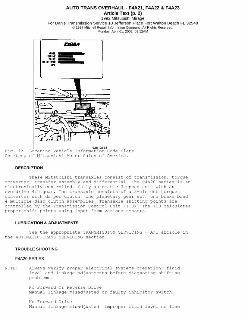
Vehicle information code plate is riveted to firewall inengine compartment area. See Fig. 1.
AUTO TRANS OVERHAUL - F4A21, F4A22 & F4A23Article Text (p. 2)
1992 Mitsubishi MirageFor Dan's Transmission Service 10 Jefferson Place Fort Walton Beach FL 32548
© 1997 Mitchell Repair Information Company, All Rights Reserved.Monday, April 01, 2002 09:12AM
Fig. 1: Locating Vehicle Information Code PlateCourtesy of Mitsubishi Motor Sales of America.
DESCRIPTION
These Mitsubishi transaxles consist of transmission, torqueconverter, transfer assembly and differential. The F4A20 series is anelectronically controlled, fully automatic 3-speed unit with anoverdrive 4th gear. The transaxle consists of a 3-element torqueconverter with damper clutch, one planetary gear set, one brake band,4 multiple-disc clutch assemblies. Transaxle shifting points arecontrolled by the Transmission Control Unit (TCU). The TCU calculatesproper shift points using input from various sensors.
LUBRICATION & ADJUSTMENTS
See the appropriate TRANSMISSION SERVICING - A/T article inthe AUTOMATIC TRANS SERVICING section.
TROUBLE SHOOTING
F4A20 SERIES
NOTE: Always verify proper electrical systems operation, fluid level and linkage adjustments before diagnosing shifting problems.
No Forward Or Reverse Drive Manual linkage misadjusted,or faulty inhibitor switch.
No Forward Drive Manual linkage misadjusted, improper fluid level or line
AUTO TRANS OVERHAUL - F4A21, F4A22 & F4A23Article Text (p. 3)
1992 Mitsubishi MirageFor Dan's Transmission Service 10 Jefferson Place Fort Walton Beach FL 32548
© 1997 Mitchell Repair Information Company, All Rights Reserved.Monday, April 01, 2002 09:12AM
pressure, one-way clutch or oil pump failure, faulty valve body orpressure control valve stuck open.
No Reverse Drive Manual linkage misadjusted, improper fluid level or linepressure, torque converter failure, faulty valve body, worn frontclutch, low and reverse brake, missing "O" ring in low and reversecircuit or faulty pulse generator "B".
Engine Stalls When Shifted To "D" Or "R" Insufficient engine performance, faulty valve body or damperclutch.
Slips In Drive Manual linkage misadjusted, low fluid level or line pressure,one-way clutch failure, faulty valve body, sticking pressure controlvalve or worn rear clutch.
Slips In Reverse Manual linkage misadjusted, low fluid level or line pressure,faulty low and reverse brake circuit or front clutch, stickingpressure control valve, missing "O" ring in low and reverse circuit orfaulty valve body.
Stall RPM Too Low Insufficient engine performance or torque converter failure.
Vehicle Creeps In "N" Manual linkage misadjusted, parking mechanism failure, faultyinhibitor switch or faulty valve body.
Park Will Not Engage Manual linkage misadjusted or parking mechanism failure.
Excessive Shock When Shifting To "R", "L", 2 Or "D" Improper engine idle speed or manual linkage adjustment,faulty valve body, front clutch, rear clutch or low and reverse brake,misadjusted inhibitor switch, misadjusted TPS, overdrive switchfailure or TCU failure.
No 2-3 Upshift Faulty valve body, worn front clutch, pressure control valvesticking or faulty control unit.
No 3-4 Upshift Malfunctioning end clutch, misadjusted manual linkage, faultyoverdrive switch, or faulty control unit.
Overdrive Switch Inoperative Faulty overdrive switch or faulty control unit
Incorrect Shift Points Faulty TPS, faulty valve body, faulty pulse generator "B",poor ignition switch contact or TCU failure.
Vehicle Starts Off In Second Speed
AUTO TRANS OVERHAUL - F4A21, F4A22 & F4A23Article Text (p. 4)
1992 Mitsubishi MirageFor Dan's Transmission Service 10 Jefferson Place Fort Walton Beach FL 32548
© 1997 Mitchell Repair Information Company, All Rights Reserved.Monday, April 01, 2002 09:12AM
Misadjusted manual linkage, torque converter failure, faultyvalve body, faulty inhibitor switch, faulty accelerator switch or TCUfailure.
Excessive Shift Shock On 1-2 Or 3-4 Upshift Faulty valve body, faulty kickdown band, kickdown servomisadjusted, faulty end clutch, misadjusted TPS, faulty pulsegenerator "A", faulty kickdown servo switch, faulty ignition signalsystem or TCU failure.
Excessive Shift Shock On Upshift Faulty or misadjusted TPS, faulty valve body, faulty frontclutch, faulty pulse generator "A", faulty ignition signal system.
Excessive Shift Shock On "D"-2 Downshift Faulty valve body, misadjusted TPS, faulty pulse generator"A", faulty ignition signal system, faulty low and reverse brake orpiston.
Engine Flares On Upshift Low line pressure, misadjusted TPS, low fluid level, faultyvalve body, faulty front or end clutch, faulty kickdown band, kickdownservo misadjusted, faulty pulse generator "A", faulty ignition signalsystem, faulty control valve or TCU.
Engine Flares On 3-2 Downshift Low line pressure, faulty oil pump, worn front clutch, lowfluid level, faulty valve body, faulty kickdown band, kickdown servomisadjusted, faulty pulse generator "A", misadjusted TPS, faultykickdown servo switch, faulty ignition signal system, faulty controlvalve or TCU.
Excessive Shift Shock Cold Faulty valve body or TCU.
Damper Clutch Inoperative Torque converter failure, faulty valve body, faulty throttleposition sensor, faulty pulse generator "A" or "B", faulty ignitionsignal system, damper clutch control solenoid open, faulty ormisadjusted accelerator switch, faulty oil temperature sensor orfaulty TCU.
Whining Noise From Converter Housing Oil pump failure.
Rattling Noise From Converter Housing Cracked flexplate or loose torque converter-to-flexplatebolt.
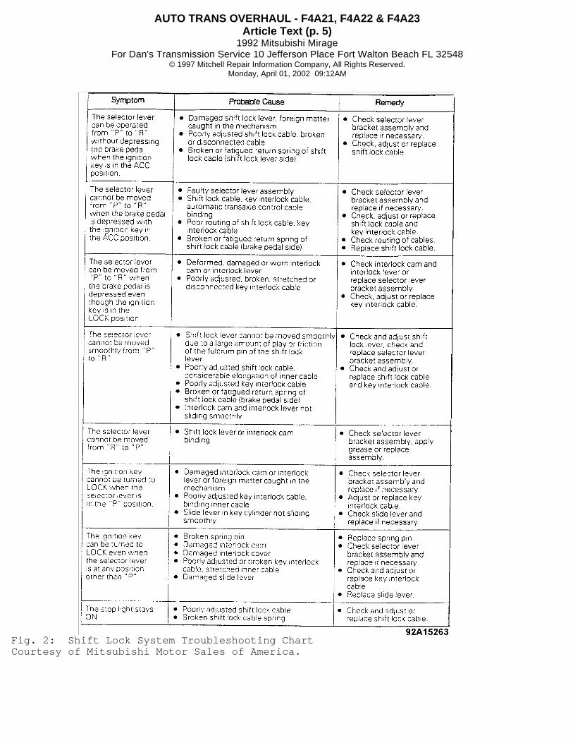
SHIFT-LOCK SYSTEM
AUTO TRANS OVERHAUL - F4A21, F4A22 & F4A23Article Text (p. 5)
1992 Mitsubishi MirageFor Dan's Transmission Service 10 Jefferson Place Fort Walton Beach FL 32548
© 1997 Mitchell Repair Information Company, All Rights Reserved.Monday, April 01, 2002 09:12AM
Fig. 2: Shift Lock System Troubleshooting ChartCourtesy of Mitsubishi Motor Sales of America.

AUTO TRANS OVERHAUL - F4A21, F4A22 & F4A23Article Text (p. 6)
1992 Mitsubishi MirageFor Dan's Transmission Service 10 Jefferson Place Fort Walton Beach FL 32548
© 1997 Mitchell Repair Information Company, All Rights Reserved.Monday, April 01, 2002 09:12AM
Fig. 3: Clutch, Band & Brake Application ChartCourtesy of Mitsubishi Motor Sales of America.
TESTING
NOTE: See Fig. 3 for clutch, band and brake application chart.
SELF-DIAGNOSTIC TEST (F4A20 SERIES)
Self-Diagnostic Capabilities 1) Use an analog voltmeter or tester and diagnostic connectorlocated at fuse block to read fault codes. See Fig. 4. 2) Random Access Memory (RAM) of TCU is capable of storing upto 10 different fault codes. Fault codes are stored in order ofoccurrence. One fault code can be stored up to 3 times. 3) If 10 fault codes have already been stored, addition ofone or more new fault codes will cause the oldest codes to be cleared. 4) Stored fault codes are cleared when battery isdisconnected. Fail-safe system activation locks transaxle in 3rd gearand allows vehicle operation in event of system malfunction. 5) Fail-safe fault codes are also stored in RAM. Up to 3fail-safe codes can be stored. 6) Fail-safe operation (locked in 3rd) is cancelled whenignition switch is cycled OFF, but fail-safe code is retained in RAM.
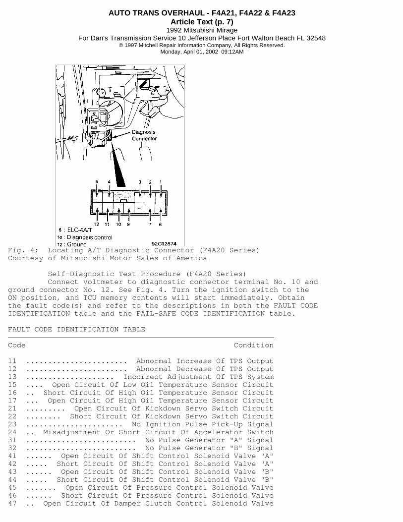
AUTO TRANS OVERHAUL - F4A21, F4A22 & F4A23Article Text (p. 7)
1992 Mitsubishi MirageFor Dan's Transmission Service 10 Jefferson Place Fort Walton Beach FL 32548
© 1997 Mitchell Repair Information Company, All Rights Reserved.Monday, April 01, 2002 09:12AM
Fig. 4: Locating A/T Diagnostic Connector (F4A20 Series)Courtesy of Mitsubishi Motor Sales of America
Self-Diagnostic Test Procedure (F4A20 Series) Connect voltmeter to diagnostic connector terminal No. 10 andground connector No. 12. See Fig. 4. Turn the ignition switch to theON position, and TCU memory contents will start immediately. Obtainthe fault code(s) and refer to the descriptions in both the FAULT CODEIDENTIFICATION table and the FAIL-SAFE CODE IDENTIFICATION table.
FAULT CODE IDENTIFICATION TABLE� � � � � � � � � � � � � � � � � � � � � � � � � � � � � � � � � � � � � � � � � � � � � � � � � � � � � � � � � � � �
Code Condition
11 ....................... Abnormal Increase Of TPS Output12 ....................... Abnormal Decrease Of TPS Output13 .................... Incorrect Adjustment Of TPS System15 .... Open Circuit Of Low Oil Temperature Sensor Circuit16 .. Short Circuit Of High Oil Temperature Sensor Circuit17 ... Open Circuit Of High Oil Temperature Sensor Circuit21 ......... Open Circuit Of Kickdown Servo Switch Circuit22 ........ Short Circuit Of Kickdown Servo Switch Circuit23 ...................... No Ignition Pulse Pick-Up Signal24 .. Misadjustment Or Short Circuit Of Accelerator Switch31 ......................... No Pulse Generator "A" Signal32 ......................... No Pulse Generator "B" Signal41 ...... Open Circuit Of Shift Control Solenoid Valve "A"42 ..... Short Circuit Of Shift Control Solenoid Valve "A"43 ...... Open Circuit Of Shift Control Solenoid Valve "B"44 ..... Short Circuit Of Shift Control Solenoid Valve "B"45 ....... Open Circuit Of Pressure Control Solenoid Valve46 ...... Short Circuit Of Pressure Control Solenoid Valve47 .. Open Circuit Of Damper Clutch Control Solenoid Valve

AUTO TRANS OVERHAUL - F4A21, F4A22 & F4A23Article Text (p. 8)
1992 Mitsubishi MirageFor Dan's Transmission Service 10 Jefferson Place Fort Walton Beach FL 32548
© 1997 Mitchell Repair Information Company, All Rights Reserved.Monday, April 01, 2002 09:12AM
48 . Short Circuit Of Damper Clutch Control Solenoid Valve49 ................... Malfunction Of Damper Clutch System51 ...... 1st Gear Non-Synchronous - Pulse Generator(s) Or Kickdown Brake52 ..... 2nd Gear Non-Synchronous - Pulse Generator "A" Or Kickdown Brake53 ...... 3rd Gear Non-Synchronous - Pulse Generator(s) Or Front Or Rear Clutch54 ..... 4th Gear Non-Synchronous - Pulse Generator "A" Or Kickdown Brake� � � � � � � � � � � � � � � � � � � � � � � � � � � � � � � � � � � � � � � � � � � � � � � � � � � � � � � � � � � �
FAIL-SAFE CODE IDENTIFICATION TABLE� � � � � � � � � � � � � � � � � � � � � � � � � � � � � � � � � � � � � � � � � � � � � � � � � � � � � � � � � � � �
Code Condition
81 ................... Open Circuit Of Pulse Generator "A"82 ................... Open Circuit Of Pulse Generator "B"83 ........ Shift Control Solenoid Valve "A" Short Circuit84 ........ Shift Control Solenoid Valve "B" Short Circuit85 ....... Pressure Control Solenoid Valve Circuit Failure86 ........................... Shift Steps Non-Synchronous� � � � � � � � � � � � � � � � � � � � � � � � � � � � � � � � � � � � � � � � � � � � � � � � � � � � � � � � � � � �
ELECTRONIC COMPONENT TEST (F4A20 SERIES)
ELECTRONIC COMPONENT TESTING FLOWCHART INDEX (F4A20 SERIES)� � � � � � � � � � � � � � � � � � � � � � � � � � � � � � � � � � � � � � � � � � � � � � � � � � � � � � � � � � � �
Component Illustration
System Wiring ..................................... Fig. 5Oil Temperature Sensor ............................ Fig. 5Throttle Position Sensor .......................... Fig. 5Pulse Generator "A" or "B" ........................ Fig. 6Pressure Control Solenoid Valve (PSCV) ............ Fig. 7Shift-Control Solenoid Valve (SCSV) "A" Or "B" .......................... Fig. 7Damper Clutch System .............................. Fig. 8Damper Clutch Control Solenoid Valve (DCCSV) ........................... Fig. 9Accelerator Switch ............................... Fig. 10Inhibitor Switch ................................. Fig. 10Kickdown (K/D) Servo Switch ...................... Fig. 11Transaxle Control Unit (TCU) ..................... Fig. 11� � � � � � � � � � � � � � � � � � � � � � � � � � � � � � � � � � � � � � � � � � � � � � � � � � � � � � � � � � � �

AUTO TRANS OVERHAUL - F4A21, F4A22 & F4A23Article Text (p. 9)
1992 Mitsubishi MirageFor Dan's Transmission Service 10 Jefferson Place Fort Walton Beach FL 32548
© 1997 Mitchell Repair Information Company, All Rights Reserved.Monday, April 01, 2002 09:12AM
Fig. 5: Electronic Component Testing (F4A20 Series - 1 of 7)Courtesy of Mitsubishi Motor Sales of America.

AUTO TRANS OVERHAUL - F4A21, F4A22 & F4A23Article Text (p. 10)
1992 Mitsubishi MirageFor Dan's Transmission Service 10 Jefferson Place Fort Walton Beach FL 32548
© 1997 Mitchell Repair Information Company, All Rights Reserved.Monday, April 01, 2002 09:12AM
Fig. 6: Electronic Component Testing (F4A20 Series - 2 of 7)Courtesy of Mitsubishi Motor Sales of America.
AUTO TRANS OVERHAUL - F4A21, F4A22 & F4A23Article Text (p. 11)
1992 Mitsubishi MirageFor Dan's Transmission Service 10 Jefferson Place Fort Walton Beach FL 32548
© 1997 Mitchell Repair Information Company, All Rights Reserved.Monday, April 01, 2002 09:12AM
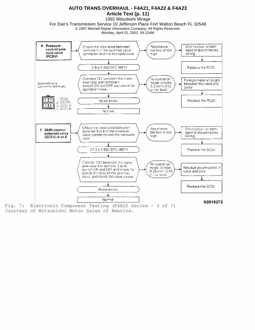
Fig. 7: Electronic Component Testing (F4A20 Series - 3 of 7)Courtesy of Mitsubishi Motor Sales of America.
AUTO TRANS OVERHAUL - F4A21, F4A22 & F4A23Article Text (p. 12)
1992 Mitsubishi MirageFor Dan's Transmission Service 10 Jefferson Place Fort Walton Beach FL 32548
© 1997 Mitchell Repair Information Company, All Rights Reserved.Monday, April 01, 2002 09:12AM
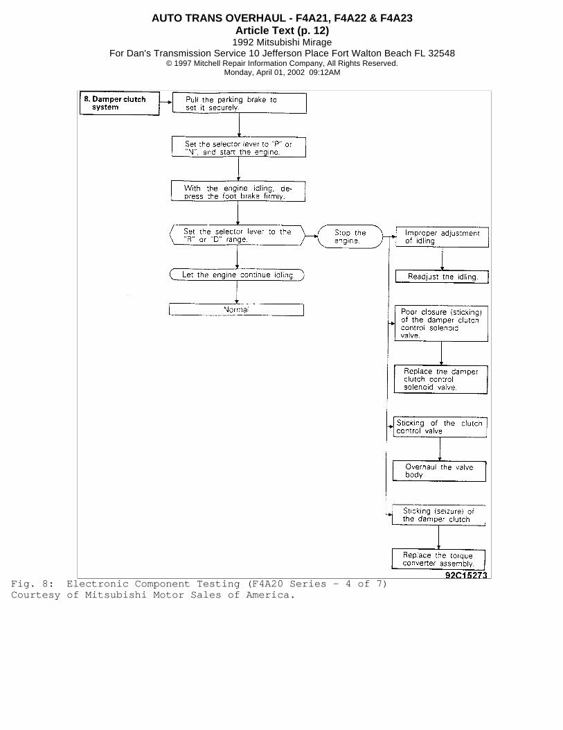
Fig. 8: Electronic Component Testing (F4A20 Series - 4 of 7)Courtesy of Mitsubishi Motor Sales of America.

AUTO TRANS OVERHAUL - F4A21, F4A22 & F4A23Article Text (p. 13)
1992 Mitsubishi MirageFor Dan's Transmission Service 10 Jefferson Place Fort Walton Beach FL 32548
© 1997 Mitchell Repair Information Company, All Rights Reserved.Monday, April 01, 2002 09:12AM
Fig. 9: Electronic Component Testing (F4A20 Series - 5 of 7)Courtesy of Mitsubishi Motor Sales of America.

AUTO TRANS OVERHAUL - F4A21, F4A22 & F4A23Article Text (p. 14)
1992 Mitsubishi MirageFor Dan's Transmission Service 10 Jefferson Place Fort Walton Beach FL 32548
© 1997 Mitchell Repair Information Company, All Rights Reserved.Monday, April 01, 2002 09:12AM
Fig. 10: Electronic Component Testing (F4A20 Series - 6 of 7)Courtesy of Mitsubishi Motor Sales of America.

AUTO TRANS OVERHAUL - F4A21, F4A22 & F4A23Article Text (p. 15)
1992 Mitsubishi MirageFor Dan's Transmission Service 10 Jefferson Place Fort Walton Beach FL 32548
© 1997 Mitchell Repair Information Company, All Rights Reserved.Monday, April 01, 2002 09:12AM
Fig. 11: Electronic Component Testing (F4A20 Series - 7 of 7)Courtesy of Mitsubishi Motor Sales of America.
ROAD TEST
Before performing road test ensure fluid level is okay andcontrol cable adjustments have been checked. During road test,transaxle must be checked for slipping of each friction element, ashock felt at engagement or proper upshift or downshift points. SeeFigs. 3, and 12 to 14.

AUTO TRANS OVERHAUL - F4A21, F4A22 & F4A23Article Text (p. 16)
1992 Mitsubishi MirageFor Dan's Transmission Service 10 Jefferson Place Fort Walton Beach FL 32548
© 1997 Mitchell Repair Information Company, All Rights Reserved.Monday, April 01, 2002 09:12AM
Fig. 12: Shift Pattern Chart (1 of 3)Courtesy of Mitsubishi Motor Sales of America.

AUTO TRANS OVERHAUL - F4A21, F4A22 & F4A23Article Text (p. 17)
1992 Mitsubishi MirageFor Dan's Transmission Service 10 Jefferson Place Fort Walton Beach FL 32548
© 1997 Mitchell Repair Information Company, All Rights Reserved.Monday, April 01, 2002 09:12AM
Fig. 13: Shift Pattern Chart (2 of 3)Courtesy of Mitsubishi Motor Sales of America.

AUTO TRANS OVERHAUL - F4A21, F4A22 & F4A23Article Text (p. 18)
1992 Mitsubishi MirageFor Dan's Transmission Service 10 Jefferson Place Fort Walton Beach FL 32548
© 1997 Mitchell Repair Information Company, All Rights Reserved.Monday, April 01, 2002 09:12AM
Fig. 14: Shift Pattern Chart (3 of 3)Courtesy of Mitsubishi Motor Sales of America.
HYDRAULIC PRESSURE TESTS
NOTE: In these testing procedures, an additional person may be necessary to activate the transmission throttle control cable. Before performing pressure tests ensure fluid level and condition are acceptable.
Pressure Test (F4A20 Series) 1) Pressure testing is an important step in diagnosticprocedure. Ensure fluid is at operating temperature of 160-180
�
F (70-80
�
C). Raise and support vehicle. Install engine tachometer so it canbe seen from driver seat. When testing reverse pressure, use 400-psigauge. See Fig. 15. 2) Measure oil pressure under various conditions. Compare

AUTO TRANS OVERHAUL - F4A21, F4A22 & F4A23Article Text (p. 19)
1992 Mitsubishi MirageFor Dan's Transmission Service 10 Jefferson Place Fort Walton Beach FL 32548
© 1997 Mitchell Repair Information Company, All Rights Reserved.Monday, April 01, 2002 09:12AM
results with specifications in Fig. 16.
Fig. 15: Locating Pressure Test Ports (F4A20 Series)Courtesy of Mitsubishi Motor Sales of America
Fig. 16: Testing Transaxle Hydraulic Pressures (F4A20 Series)Courtesy of Mitsubishi Motor Sales of America
AUTO TRANS OVERHAUL - F4A21, F4A22 & F4A23Article Text (p. 20)
1992 Mitsubishi MirageFor Dan's Transmission Service 10 Jefferson Place Fort Walton Beach FL 32548
© 1997 Mitchell Repair Information Company, All Rights Reserved.Monday, April 01, 2002 09:12AM
Pressure Test Results (F4A20 Series) 1) If kickdown brake, front clutch, end clutch and low-reverse brake pressures are all low probable causes are: clogged oilfilter, incorrect pressure regulator adjustment, sticking pressureregulator valve, incorrect oil pump discharge pressure or fluidpressure leakage at valve body. 2) Incorrect reducing pressure reading indicates: incorrectline pressure, reducing pressure filter clogging, reducing valvesticking or fluid pressure leakage at valve body. 3) Incorrect kickdown brake pressure reading indicates:fluid pressure leakage at kickdown servo or valve body malfunction. 4) Incorrect front clutch pressure reading indicates fluidpressure leakage at kickdown servo or valve body, malfunction of valvebody or fluid pressure leakage at front clutch piston or retainer. 5) Incorrect end clutch pressure reading indicates: fluidleakage at end clutch piston, fluid pressure leakage at valve body orvalve body malfunction. 6) Incorrect low-reverse brake pressure reading indicates:fluid pressure leakage between valve body and transaxle case at "O"ring, valve body malfunction or fluid pressure leakage at low-reversebrake piston or retainer. 7) Incorrect torque converter pressure indicates: cloggingor leaking of oil cooler or lines, torque converter failure, leakingseal ring at input shaft or binding Damper Clutch Control SolenoidValve (DCCSV) or damper control valve.
STALL TEST
CAUTION: DO NOT allow anyone to stand in front of or behind vehicle while performing stall test. Always block both rear wheels and apply parking and service brakes fully.
Stall Test Procedure 1) Check transaxle fluid level. Fluid should be at normaloperating temperature of 160-180
�
F (70-80�
C). Engine coolant shouldalso be at normal operating temperature of 180-190
�
F (60-90�
C). 2) Block both rear wheels. Install engine tachometer to beseen from driver's seat. Apply parking and service brakes fully. Startengine and move gear selector to "D" range. 3) With brakes fully applied, depress accelerator pedal fullyto read maximum engine RPM. See STALL SPEED SPECIFICATIONS table.
NOTE: DO NOT hold wide open throttle for longer than 5 seconds at a time. If more than one stall test is required, operate engine at approximately 1000 RPM in neutral for 2 minutes to cool transaxle fluid.
4) Move gear selector to "R" range and repeat stall testprocedure. See STALL SPEED SPECIFICATIONS table.
Stall Test Results 1) If stall speed is above specification in "D" range, rearclutch or overrunning clutch is slipping. HYDRAULIC PRESSURE TESTS canbe performed to isolate problem. 2) If stall speed is above specification in "R" range, front

AUTO TRANS OVERHAUL - F4A21, F4A22 & F4A23Article Text (p. 21)
1992 Mitsubishi MirageFor Dan's Transmission Service 10 Jefferson Place Fort Walton Beach FL 32548
© 1997 Mitchell Repair Information Company, All Rights Reserved.Monday, April 01, 2002 09:12AM
clutch or low-reverse brake is slipping. HYDRAULIC PRESSURE TESTS canbe performed to isolate problem. 3) If stall speed is below specification in "R" and "D"ranges, insufficient engine performance or faulty torque converter areprobable causes.
STALL SPEED SPECIFICATIONS TABLE� � � � � � � � � � � � � � � � � � � � � � � � � � � � � � � � � � � � � � � � � � � � � � � � � � � � � � � � � � � �
Transaxle Model Stall Speed RPM
F4A20 Series ..................................... 1800-2800� � � � � � � � � � � � � � � � � � � � � � � � � � � � � � � � � � � � � � � � � � � � � � � � � � � � � � � � � � � �
ON-VEHICLE SERVICE
INHIBITOR SWITCH & CONTROL CABLE ADJUSTMENTS
See the appropriate TRANSMISSION SERVICING - A/T article inthe AUTOMATIC TRANS SERVICING section.
THROTTLE CONTROL CABLE ADJUSTMENT
See the appropriate TRANSMISSION SERVICING - A/T article inthe AUTOMATIC TRANS SERVICING section.
THROTTLE POSITION SENSOR ADJUSTMENT
See the appropriate TRANSMISSION SERVICING - A/T article inthe AUTOMATIC TRANS SERVICING section.
KICKDOWN SERVO ADJUSTMENT (F4A20 SERIES W/MITSUBISHI TOOL)
1) Thoroughly clean area around kickdown servo switch. Removesnap ring. Remove kickdown servo switch. Using Kickdown Servo Wrench(MD998918) and Wrench Adapter (MD998915-A), secure kickdown servopiston from turning. See Fig. 17.
CAUTION: DO NOT press piston inward while engaging wrench in piston. Tighten wrench adapter by hand.
2) Loosen lock nut back to "V" groove in adjusting rod. SeeFig. 18. Thread inner half of Kickdown Servo Socket Wrench Set(MD998916) onto adjusting rod, and tighten it until it contacts locknut. See Fig. 19. Place outer half of wrench set onto lock nut.Tighten inner and outer halves together using open end wrenches.

AUTO TRANS OVERHAUL - F4A21, F4A22 & F4A23Article Text (p. 22)
1992 Mitsubishi MirageFor Dan's Transmission Service 10 Jefferson Place Fort Walton Beach FL 32548
© 1997 Mitchell Repair Information Company, All Rights Reserved.Monday, April 01, 2002 09:12AM
Fig. 17: Installing Kickdown Servo WrenchCourtesy of Mitsubishi Motor Sales of America.
Fig. 18: Sectional View of Kickdown Servo Adjustment MechanismCourtesy of Mitsubishi Motor Sales of America.
Fig. 19: Locking Servo Wrench to Adjusting RodCourtesy of Mitsubishi Motor Sales of America.
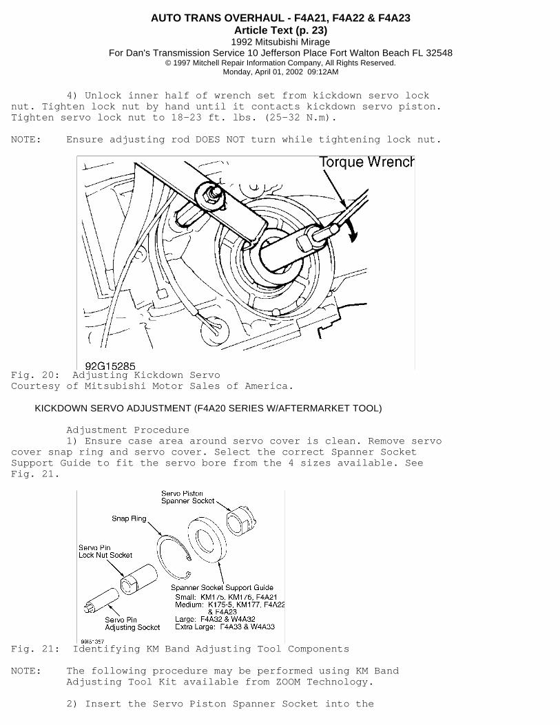
3) Remove outer half of wrench set. Using a torquewrench, tighten inner half of wrench set to 7.2 ft. lbs. (10 N.m).See Fig. 20. Back off wrench and repeat tightening to specifiedtorque. Back off wrench once again, then tighten to 3.6 ft. lbs.(5 N.m). When specified torque is reached, back off wrench 2-2 1/4turns.
AUTO TRANS OVERHAUL - F4A21, F4A22 & F4A23Article Text (p. 23)
1992 Mitsubishi MirageFor Dan's Transmission Service 10 Jefferson Place Fort Walton Beach FL 32548
© 1997 Mitchell Repair Information Company, All Rights Reserved.Monday, April 01, 2002 09:12AM
4) Unlock inner half of wrench set from kickdown servo locknut. Tighten lock nut by hand until it contacts kickdown servo piston.Tighten servo lock nut to 18-23 ft. lbs. (25-32 N.m).
NOTE: Ensure adjusting rod DOES NOT turn while tightening lock nut.
Fig. 20: Adjusting Kickdown ServoCourtesy of Mitsubishi Motor Sales of America.
KICKDOWN SERVO ADJUSTMENT (F4A20 SERIES W/AFTERMARKET TOOL)
Adjustment Procedure 1) Ensure case area around servo cover is clean. Remove servocover snap ring and servo cover. Select the correct Spanner SocketSupport Guide to fit the servo bore from the 4 sizes available. SeeFig. 21.
Fig. 21: Identifying KM Band Adjusting Tool Components
NOTE: The following procedure may be performed using KM Band Adjusting Tool Kit available from ZOOM Technology.
2) Insert the Servo Piston Spanner Socket into the

AUTO TRANS OVERHAUL - F4A21, F4A22 & F4A23Article Text (p. 24)
1992 Mitsubishi MirageFor Dan's Transmission Service 10 Jefferson Place Fort Walton Beach FL 32548
© 1997 Mitchell Repair Information Company, All Rights Reserved.Monday, April 01, 2002 09:12AM
counterbored side of the Spanner Socket Support Guide. Insert thesecomponents into the servo bore. Slowly by hand, rotate the ServoPiston Spanner Socket until the lugs engage the cutouts on the servopiston. The tool is fully seated when the snap ring groove iscompletely exposed. 3) Install the snap ring in the exposed groove. If necessary,rotate the Servo Piston Spanner Socket to allow ease of installationof a 1 1/2" wrench to the socket. This should be done prior toloosening the servo pin lock nut. 4) Insert the Servo Pin Lock Nut Socket into the Servo PistonSpanner Socket. Turn the socket by hand until it has engaged the locknut. Insert the Servo Pin Adjusting Socket into the Servo Pin Lock NutSocket and rotate by hand until it engages the servo pin. See Fig. 22. 5) Using a 1 1/2" wrench or adjustable wrench, hold the ServoPiston Spanner Socket stationary.
CAUTION: DO NOT use pliers or a pipe wrench to hold the Servo Piston Spanner Socket stationary. This may cause injury to the user or damage to the tool.
6) Using a 1 1/16" wrench, on the Servo Pin Lock Nut Socket,loosen the servo pin lock nut by turning it counter clockwise. SeeFig. 23. With one hand, push firmly inward on the Servo Pin AdjustingSocket. Using 2 fingers, turn the Servo Pin Lock Nut Socket counterclockwise until it contacts the bottom of the Servo Pin AdjustingSocket. 7) Using an INCH Lb. torque wrench and a shallow 1/2" 6-pointsocket, torque the Servo Pin Adjusting Socket to 86 INCH Lbs. Loosenthe Servo Pin Adjusting Socket 2 or 3 turns and repeat the tighteningprocedure to 86 INCH Lbs. Loosen again and apply a final torque of 43INCH Lbs. to the Servo Pin Adjusting Socket. See Fig. 24. 8) Using a 1/2" wrench, loosen the Servo Pin Adjusting Socket2-2 1/4 complete turns. Hold the Servo Pin Adjusting Socket stationaryand rotate the Servo Pin Lock Nut Socket clockwise until the servo pinlock nut firmly contacts the servo piston. Remove the Servo PinAdjusting Socket. 9) Using a 1 1/2" wrench, hold the Servo Pin Spanner Socketstationary. Use a 1 1/16" wrench to tighten the servo lock pin nutwith the Servo Pin Lock Nut Socket. Tighten the nut to approximately18 ft. lbs. See Fig. 23. 10) Remove the snap ring and all remaining band adjustingtool components. Install the servo cover and snap ring. Ensure thesharp edge of the snap ring faces outward.

AUTO TRANS OVERHAUL - F4A21, F4A22 & F4A23Article Text (p. 25)
1992 Mitsubishi MirageFor Dan's Transmission Service 10 Jefferson Place Fort Walton Beach FL 32548
© 1997 Mitchell Repair Information Company, All Rights Reserved.Monday, April 01, 2002 09:12AM
Fig. 22: KM Band Adjusting Tool Installation
Fig. 23: Loosening Or Tightening Servo Pin Lock Nut
Fig. 24: Adjusting Servo Pin
REMOVAL & INSTALLATION
See the appropriate TRANSMISSION REMOVAL & INSTALLATION - A/Tarticle in the AUTOMATIC TRANS SERVICING section.
AUTO TRANS OVERHAUL - F4A21, F4A22 & F4A23Article Text (p. 26)
1992 Mitsubishi MirageFor Dan's Transmission Service 10 Jefferson Place Fort Walton Beach FL 32548
© 1997 Mitchell Repair Information Company, All Rights Reserved.Monday, April 01, 2002 09:12AM
TORQUE CONVERTER
Torque converter is a sealed unit and cannot be disassembledfor service. Replace unit if damaged or contaminated.
TRANSAXLE DISASSEMBLY
F4A20 Series 1) Prior to disassembly, plug all openings and thoroughlyclean exterior of transaxle. Remove torque converter and measure inputshaft end play. 2) Remove pulse generators "A" and "B" and inhibitor switch.Remove kickdown servo switch. Remove oil pan, gasket and filter.Remove oil temperature sensor. 3) Remove solenoid valve connector and valve body. Remove endclutch cover and end clutch assembly. Remove end clutch hub, thrustbearing and end clutch shaft. 4) Remove converter housing and oil pump assembly. Removedifferential assembly and spacer. Remove input shaft with front andrear clutch assemblies. Remove thrust bearing and clutch hub. Removethrust race and bearing. Remove kickdown drum and band. 5) Remove kickdown servo retainer, piston and spring. Removeanchor rod. Remove snap ring and center support. Remove reverse andforward sun gears. Remove planetary carrier assembly and thrustbearing. Remove wave spring, return spring, reaction plate, brake discand brake plate. Remove end bearing retainer. Use impact driver ifnecessary. 6) Remove idler shaft lock plate and transfer idler shaftwith Wrench Adapter (MD998344). Pull out transfer idler shaft andremove transfer idler gear bearing inner races (2) and spacer. 7) Remove snap ring from end bearing. Remove internal gear,output flange, transfer drive gear and bearing as an assembly fromcase. Remove transfer shaft cover. 8) Remove transfer shaft LEFT-HAND threaded lock nut. Removetransfer shaft with a press. Remove transfer shaft bearing using abearing splitter. Remove set screw and manual control shaft with spragrod support.
COMPONENT DISASSEMBLY & REASSEMBLY
OIL PUMP
Disassembly 1) Remove "O" ring from oil pump housing. Remove 5 bolts andreaction shaft support from housing. Remove oil pump drive and drivengears from housing. Make reassembly reference marks on drive anddriven gears. 2) Remove steel ball from housing. Remove snap ring and oilseal from oil pump drive gear. Remove 2 seal rings from reaction shaftsupport.
Inspection 1) Using a straight edge check oil pump gear side clearance.Clearance should be .0012-0.0020" (.030-.050 mm). If not withinspecification, replace oil pump as an assembly.

AUTO TRANS OVERHAUL - F4A21, F4A22 & F4A23Article Text (p. 27)
1992 Mitsubishi MirageFor Dan's Transmission Service 10 Jefferson Place Fort Walton Beach FL 32548
© 1997 Mitchell Repair Information Company, All Rights Reserved.Monday, April 01, 2002 09:12AM
2) Check reaction shaft support surface in contact with oilpump gear for evidence of interference and replace oil pump assemblyif necessary.
Reassembly 1) Fit oil seal and snap ring to oil pump drive gear. Afterimmersing drive and driven gears in ATF, install gears in pumphousing. Align reference marks made during disassembly. 2) Install steel ball in pump housing and 2 seal rings toreaction shaft support. Ensure oil pump gears turn freely. Install new"O" ring to pump housing, and lubricate. 3) Install reaction shaft support to oil pump housing andtighten 5 bolts finger tight. Align reaction shaft support with oilpump housing and torque bolts to 89-106 INCH lbs. (10-12 N.m).
FRONT CLUTCH
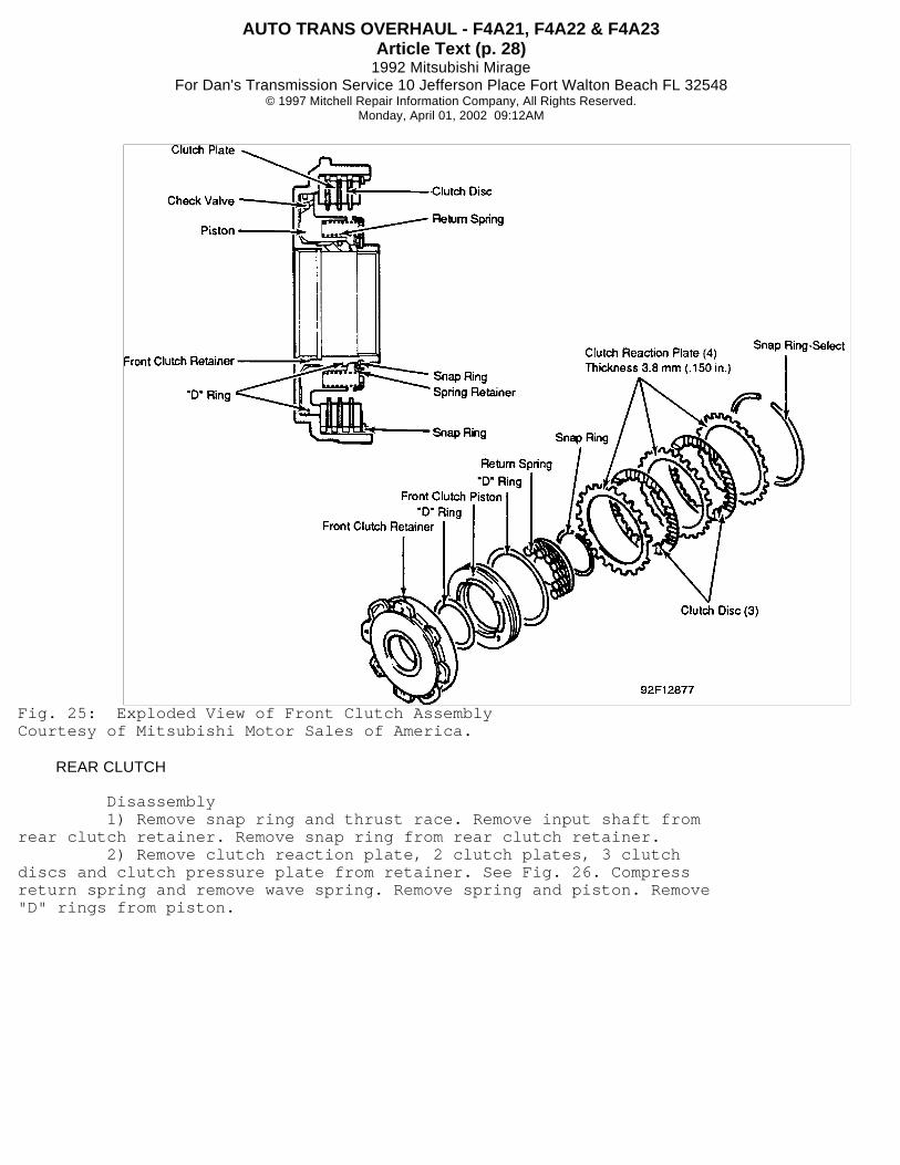
Disassembly 1) Remove snap ring from clutch retainer. Remove 4 clutchreaction plates and 3 clutch discs.
NOTE: If clutch reaction plates and clutch discs are to be reused, DO NOT change the installation order or direction.
2) Compress return spring and remove snap ring, retainer andreturn spring. Remove piston from retainer and "D" rings from pistonand retainer.
Reassembly 1) Install "D" rings in piston and retainer with round sideout. Apply ATF to outside surface of "D" rings and install piston infront clutch retainer by pushing with hand. 2) Install return spring and spring retainer. See Fig. 25.Compress return spring and install snap ring. 3) Apply ATF and install clutch reaction plates and clutchdiscs. See Fig. 25. After installing snap ring check clearance betweensnap ring and clutch reaction plate. Clearance should be .016-.024" (.40-.60 mm). Selective snap rings are available to adjust clearance.
AUTO TRANS OVERHAUL - F4A21, F4A22 & F4A23Article Text (p. 28)
1992 Mitsubishi MirageFor Dan's Transmission Service 10 Jefferson Place Fort Walton Beach FL 32548
© 1997 Mitchell Repair Information Company, All Rights Reserved.Monday, April 01, 2002 09:12AM
Fig. 25: Exploded View of Front Clutch AssemblyCourtesy of Mitsubishi Motor Sales of America.
REAR CLUTCH
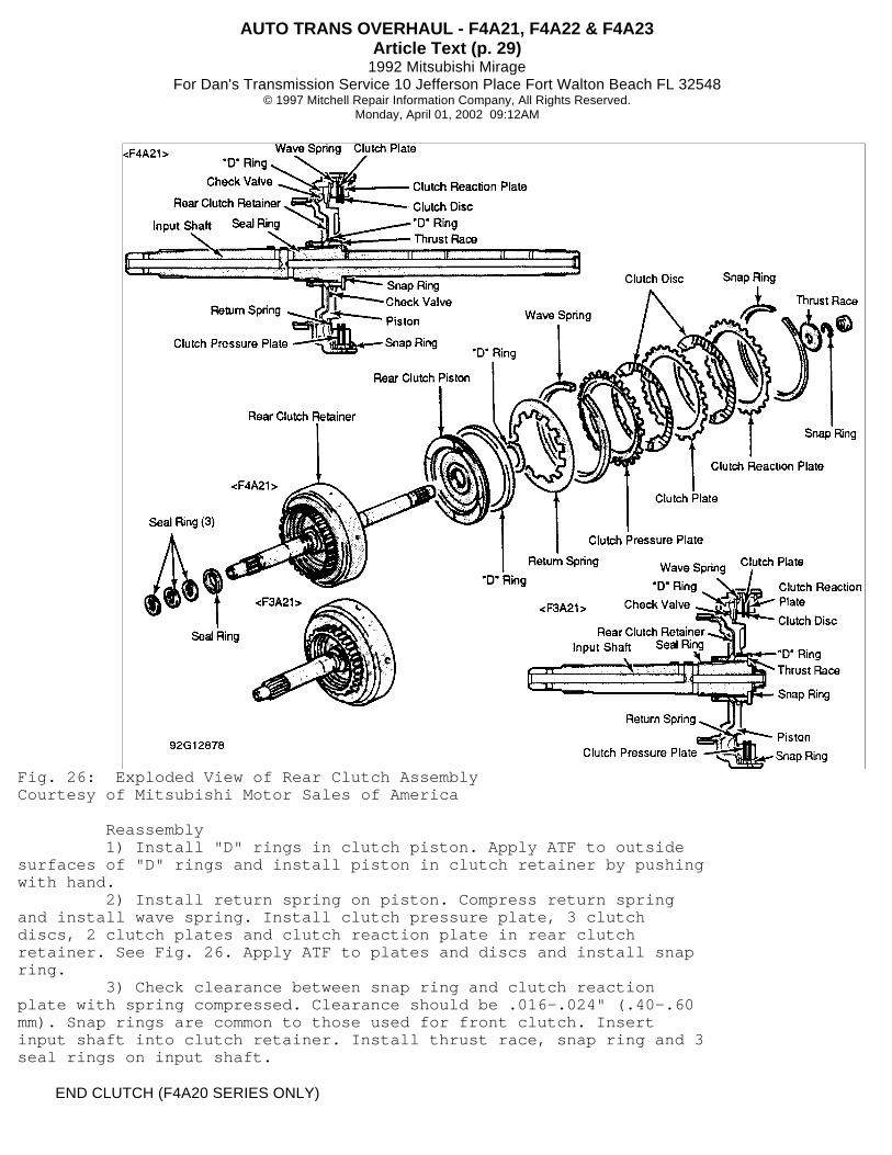
Disassembly 1) Remove snap ring and thrust race. Remove input shaft fromrear clutch retainer. Remove snap ring from rear clutch retainer. 2) Remove clutch reaction plate, 2 clutch plates, 3 clutchdiscs and clutch pressure plate from retainer. See Fig. 26. Compressreturn spring and remove wave spring. Remove spring and piston. Remove"D" rings from piston.
AUTO TRANS OVERHAUL - F4A21, F4A22 & F4A23Article Text (p. 29)
1992 Mitsubishi MirageFor Dan's Transmission Service 10 Jefferson Place Fort Walton Beach FL 32548
© 1997 Mitchell Repair Information Company, All Rights Reserved.Monday, April 01, 2002 09:12AM
Fig. 26: Exploded View of Rear Clutch AssemblyCourtesy of Mitsubishi Motor Sales of America
Reassembly 1) Install "D" rings in clutch piston. Apply ATF to outsidesurfaces of "D" rings and install piston in clutch retainer by pushingwith hand. 2) Install return spring on piston. Compress return springand install wave spring. Install clutch pressure plate, 3 clutchdiscs, 2 clutch plates and clutch reaction plate in rear clutchretainer. See Fig. 26. Apply ATF to plates and discs and install snapring. 3) Check clearance between snap ring and clutch reactionplate with spring compressed. Clearance should be .016-.024" (.40-.60mm). Snap rings are common to those used for front clutch. Insertinput shaft into clutch retainer. Install thrust race, snap ring and 3seal rings on input shaft.
END CLUTCH (F4A20 SERIES ONLY)
AUTO TRANS OVERHAUL - F4A21, F4A22 & F4A23Article Text (p. 30)
1992 Mitsubishi MirageFor Dan's Transmission Service 10 Jefferson Place Fort Walton Beach FL 32548
© 1997 Mitchell Repair Information Company, All Rights Reserved.Monday, April 01, 2002 09:12AM
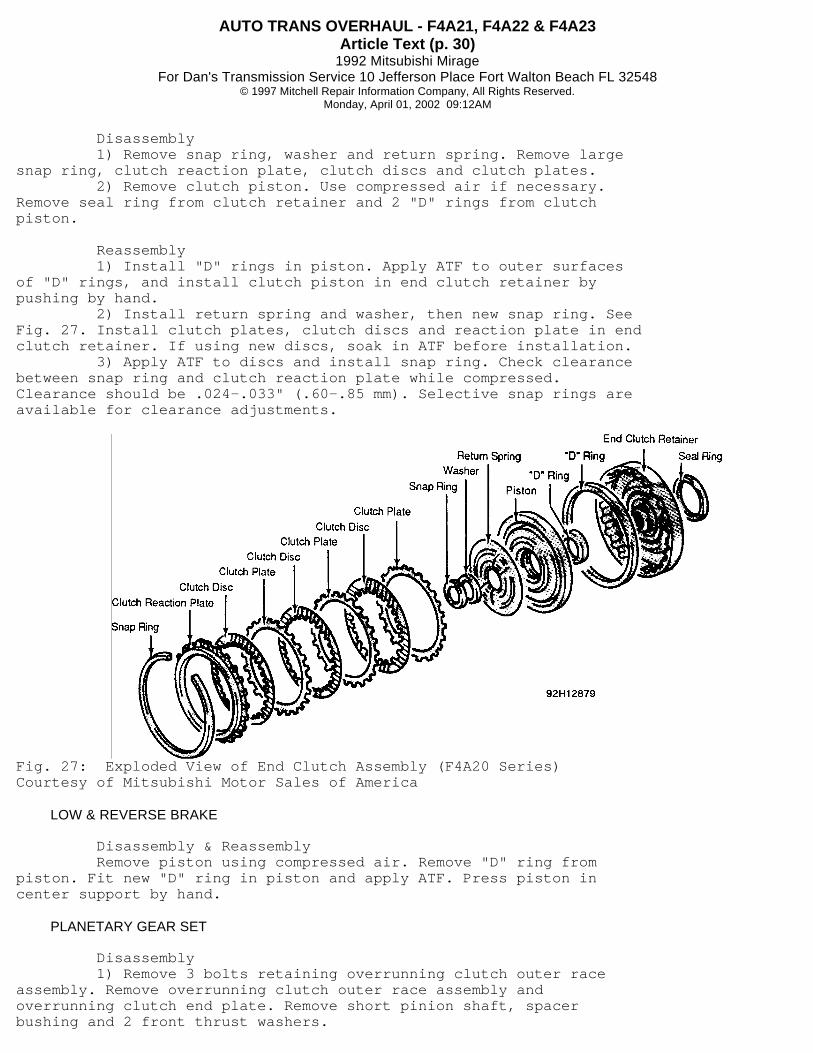
Disassembly 1) Remove snap ring, washer and return spring. Remove largesnap ring, clutch reaction plate, clutch discs and clutch plates. 2) Remove clutch piston. Use compressed air if necessary.Remove seal ring from clutch retainer and 2 "D" rings from clutchpiston.
Reassembly 1) Install "D" rings in piston. Apply ATF to outer surfacesof "D" rings, and install clutch piston in end clutch retainer bypushing by hand. 2) Install return spring and washer, then new snap ring. SeeFig. 27. Install clutch plates, clutch discs and reaction plate in endclutch retainer. If using new discs, soak in ATF before installation. 3) Apply ATF to discs and install snap ring. Check clearancebetween snap ring and clutch reaction plate while compressed.Clearance should be .024-.033" (.60-.85 mm). Selective snap rings areavailable for clearance adjustments.
Fig. 27: Exploded View of End Clutch Assembly (F4A20 Series)Courtesy of Mitsubishi Motor Sales of America
LOW & REVERSE BRAKE
Disassembly & Reassembly Remove piston using compressed air. Remove "D" ring frompiston. Fit new "D" ring in piston and apply ATF. Press piston incenter support by hand.
PLANETARY GEAR SET
Disassembly 1) Remove 3 bolts retaining overrunning clutch outer raceassembly. Remove overrunning clutch outer race assembly andoverrunning clutch end plate. Remove short pinion shaft, spacerbushing and 2 front thrust washers.
AUTO TRANS OVERHAUL - F4A21, F4A22 & F4A23Article Text (p. 31)
1992 Mitsubishi MirageFor Dan's Transmission Service 10 Jefferson Place Fort Walton Beach FL 32548
© 1997 Mitchell Repair Information Company, All Rights Reserved.Monday, April 01, 2002 09:12AM
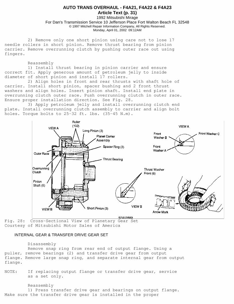
2) Remove only one short pinion using care not to lose 17needle rollers in short pinion. Remove thrust bearing from pinioncarrier. Remove overrunning clutch by pushing outer race out usingfingers.
Reassembly 1) Install thrust bearing in pinion carrier and ensurecorrect fit. Apply generous amount of petroleum jelly to insidediameter of short pinion and install 17 rollers. 2) Align holes in front and rear thrusts with shaft hole ofcarrier. Install short pinion, spacer bushing and 2 front thrustwashers and align holes. Insert pinion shaft. Install end plate inoverrunning clutch outer race. Push overrunning clutch in outer race.Ensure proper installation direction. See Fig. 28. 3) Apply petroleum jelly and install overrunning clutch endplate. Install overrunning clutch assembly to carrier and align boltholes. Torque bolts to 25-32 ft. lbs. (35-45 N.m).
Fig. 28: Cross-Sectional View of Planetary Gear SetCourtesy of Mitsubishi Motor Sales of America
INTERNAL GEAR & TRANSFER DRIVE GEAR SET
Disassembly Remove snap ring from rear end of output flange. Using apuller, remove bearings (2) and transfer drive gear from outputflange. Remove large snap ring, and separate internal gear from outputflange.
NOTE: If replacing output flange or transfer drive gear, service as a set only.
Reassembly 1) Press transfer drive gear and bearings on output flange.Make sure the transfer drive gear is installed in the proper

AUTO TRANS OVERHAUL - F4A21, F4A22 & F4A23Article Text (p. 32)
1992 Mitsubishi MirageFor Dan's Transmission Service 10 Jefferson Place Fort Walton Beach FL 32548
© 1997 Mitchell Repair Information Company, All Rights Reserved.Monday, April 01, 2002 09:12AM
direction. See Fig. 29. 2) Install output flange snap ring. This snap ring isselective; use thickest one that can be installed in groove. Standardvalue for snap ring is 0-.0236" (0-.060 mm).
Fig. 29: Exploded View of Internal & Transfer GearCourtesy of Mitsubishi Motor Sales of America.
DIFFERENTIAL
Disassembly 1) Remove drive gear and bolts from differential case. Usingpuller, remove taper roller bearing. Inspect bearing.
NOTE: When removing parts that are to be reused, mark position and direction for reference during reassembly.
2) Drive out lock pin with punch. Remove pinion shaft, piniongears and washers. Make reference marks for reassembly. 3) Remove side gears and spacers. Mark right and left sidesof gears for reference during reassembly.
Reassembly 1) Install side gears and spacers in differential case innoted positions. If new side gears are being used install spacers ofmedium thickness, .0366-.0394" (.930-1.000 mm). Install pinion gearsand washers in case and insert pinion shaft. 2) Measure backlash between pinion gear and side gear.Backlash should be .001-.006" (.025-.150 mm) and right and left handgear pairs should have equal backlash. If not within specificationselect a spacer for correct backlash. 3) Install the pinion shaft lock pin in the direction shown.See Fig. 30. After installation, ensure correct installation depth oflock pin. Projection should be less than .118" (3.00 mm).
NOTE: DO NOT reuse lock pin. Lock pin NOT requiring more than 440 lbs. (2000 N) installation load must NOT be used.
AUTO TRANS OVERHAUL - F4A21, F4A22 & F4A23Article Text (p. 33)
1992 Mitsubishi MirageFor Dan's Transmission Service 10 Jefferson Place Fort Walton Beach FL 32548
© 1997 Mitchell Repair Information Company, All Rights Reserved.Monday, April 01, 2002 09:12AM
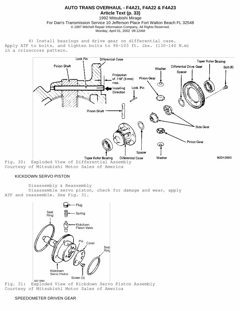
4) Install bearings and drive gear on differential case.Apply ATF to bolts, and tighten bolts to 96-103 ft. lbs. (130-140 N.m)in a crisscross pattern.
Fig. 30: Exploded View of Differential AssemblyCourtesy of Mitsubishi Motor Sales of America
KICKDOWN SERVO PISTON
Disassembly & Reassembly Disassemble servo piston, check for damage and wear, applyATF and reassemble. See Fig. 31.
Fig. 31: Exploded View of Kickdown Servo Piston AssemblyCourtesy of Mitsubishi Motor Sales of America
SPEEDOMETER DRIVEN GEAR
AUTO TRANS OVERHAUL - F4A21, F4A22 & F4A23Article Text (p. 34)
1992 Mitsubishi MirageFor Dan's Transmission Service 10 Jefferson Place Fort Walton Beach FL 32548
© 1997 Mitchell Repair Information Company, All Rights Reserved.Monday, April 01, 2002 09:12AM
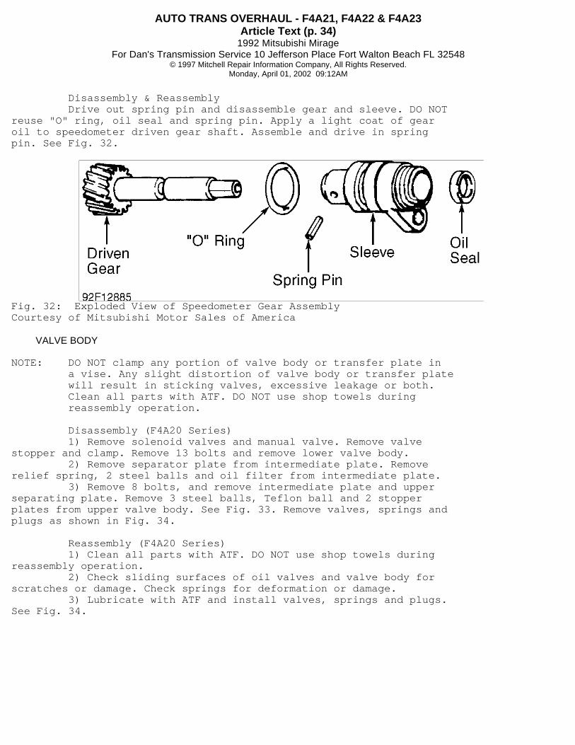
Disassembly & Reassembly Drive out spring pin and disassemble gear and sleeve. DO NOTreuse "O" ring, oil seal and spring pin. Apply a light coat of gearoil to speedometer driven gear shaft. Assemble and drive in springpin. See Fig. 32.
Fig. 32: Exploded View of Speedometer Gear AssemblyCourtesy of Mitsubishi Motor Sales of America
VALVE BODY
NOTE: DO NOT clamp any portion of valve body or transfer plate in a vise. Any slight distortion of valve body or transfer plate will result in sticking valves, excessive leakage or both. Clean all parts with ATF. DO NOT use shop towels during reassembly operation.
Disassembly (F4A20 Series) 1) Remove solenoid valves and manual valve. Remove valvestopper and clamp. Remove 13 bolts and remove lower valve body. 2) Remove separator plate from intermediate plate. Removerelief spring, 2 steel balls and oil filter from intermediate plate. 3) Remove 8 bolts, and remove intermediate plate and upperseparating plate. Remove 3 steel balls, Teflon ball and 2 stopperplates from upper valve body. See Fig. 33. Remove valves, springs andplugs as shown in Fig. 34.
Reassembly (F4A20 Series) 1) Clean all parts with ATF. DO NOT use shop towels duringreassembly operation. 2) Check sliding surfaces of oil valves and valve body forscratches or damage. Check springs for deformation or damage. 3) Lubricate with ATF and install valves, springs and plugs.See Fig. 34.

AUTO TRANS OVERHAUL - F4A21, F4A22 & F4A23Article Text (p. 35)
1992 Mitsubishi MirageFor Dan's Transmission Service 10 Jefferson Place Fort Walton Beach FL 32548
© 1997 Mitchell Repair Information Company, All Rights Reserved.Monday, April 01, 2002 09:12AM
Fig. 33: Locating Steel Balls (F4A20 Series)Courtesy of Mitsubishi Motor Sales of America

AUTO TRANS OVERHAUL - F4A21, F4A22 & F4A23Article Text (p. 36)
1992 Mitsubishi MirageFor Dan's Transmission Service 10 Jefferson Place Fort Walton Beach FL 32548
© 1997 Mitchell Repair Information Company, All Rights Reserved.Monday, April 01, 2002 09:12AM
Fig. 34: Exploded View of Valve Body Assembly (F4A20 Series)Courtesy of Mitsubishi Motor Sales of America
TRANSAXLE REASSEMBLY
1) Install brake reaction plate, brake plate and brake disc

AUTO TRANS OVERHAUL - F4A21, F4A22 & F4A23Article Text (p. 37)
1992 Mitsubishi MirageFor Dan's Transmission Service 10 Jefferson Place Fort Walton Beach FL 32548
© 1997 Mitchell Repair Information Company, All Rights Reserved.Monday, April 01, 2002 09:12AM
in transaxle case. Install a pressure plate with adequate size and fitthe return spring. Ensure return spring is installed in properdirection. 2) Apply petroleum jelly to wave spring and stick it to thecenter support. Install center support and snap ring in case. Checklow and reverse brake end play by mounting a dial indicator on rear oftransaxle case. Install dial indicator through transfer idler shafthole so its feeler is held perpendicular to brake reaction plate. 3) Using a hand pump feed air into low and reverse brake andread dial indicator deflection. Select a pressure plate to obtainspecified end play of .0315-.0394" (.800-1.000 mm). Install transfershaft bearing outer race in case. Install parking sprag rod on detentplate, then push manual control shaft in transaxle case. Torque manualcontrol shaft set screw to 71-89 INCH lbs. (8-10 N.m). 4) Install sprag rod support and torque bolts to 15-20 ft.lbs. (20-27 N.m). Install bearings on transfer shaft and install shaftin transaxle case. Using a press, install transfer driven gear. Torquetransfer shaft lock nut to 148-170 ft. lbs. (200-230 N.m) and stakelock nut to prevent loosening. 5) Measure transfer shaft end play and select a spacer whichprovides 0-.0010" (0-.025 mm) end play. Install transfer shaft cover.Assemble the planetary carrier, output flange, transfer drive gear andbearing and install in transaxle case. See Figs. 35 and 36. Installsnap ring on output flange rear bearing.

AUTO TRANS OVERHAUL - F4A21, F4A22 & F4A23Article Text (p. 38)
1992 Mitsubishi MirageFor Dan's Transmission Service 10 Jefferson Place Fort Walton Beach FL 32548
© 1997 Mitchell Repair Information Company, All Rights Reserved.Monday, April 01, 2002 09:12AM
Fig. 35: Transaxle Assembly (F3A20 & F4A20 Series - 1 of 2)Courtesy of Mitsubishi Motor Sales of America

AUTO TRANS OVERHAUL - F4A21, F4A22 & F4A23Article Text (p. 39)
1992 Mitsubishi MirageFor Dan's Transmission Service 10 Jefferson Place Fort Walton Beach FL 32548
© 1997 Mitchell Repair Information Company, All Rights Reserved.Monday, April 01, 2002 09:12AM
Fig. 36: Transaxle Assembly (F3A20 & F4A20 Series - 2 of 2)Courtesy of Mitsubishi Motor Sales of America
6) Coat transfer idler spacer and attach it to case. Install2 taper roller bearings and spacer in transfer idler gear. Place
AUTO TRANS OVERHAUL - F4A21, F4A22 & F4A23Article Text (p. 40)
1992 Mitsubishi MirageFor Dan's Transmission Service 10 Jefferson Place Fort Walton Beach FL 32548
© 1997 Mitchell Repair Information Company, All Rights Reserved.Monday, April 01, 2002 09:12AM
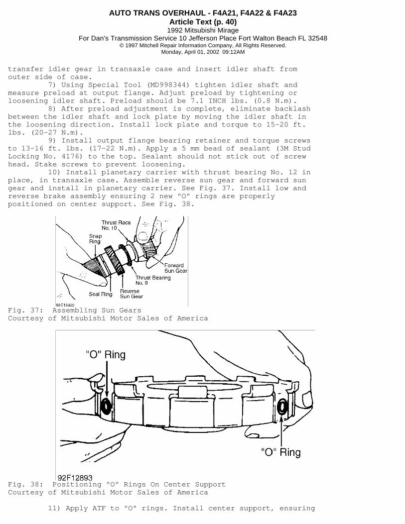
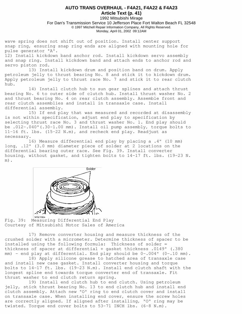
transfer idler gear in transaxle case and insert idler shaft fromouter side of case. 7) Using Special Tool (MD998344) tighten idler shaft andmeasure preload at output flange. Adjust preload by tightening orloosening idler shaft. Preload should be 7.1 INCH lbs. (0.8 N.m). 8) After preload adjustment is complete, eliminate backlashbetween the idler shaft and lock plate by moving the idler shaft inthe loosening direction. Install lock plate and torque to 15-20 ft.lbs. (20-27 N.m). 9) Install output flange bearing retainer and torque screwsto 13-16 ft. lbs. (17-22 N.m). Apply a 5 mm bead of sealant (3M StudLocking No. 4176) to the top. Sealant should not stick out of screwhead. Stake screws to prevent loosening. 10) Install planetary carrier with thrust bearing No. 12 inplace, in transaxle case. Assemble reverse sun gear and forward sungear and install in planetary carrier. See Fig. 37. Install low andreverse brake assembly ensuring 2 new "O" rings are properlypositioned on center support. See Fig. 38.
Fig. 37: Assembling Sun GearsCourtesy of Mitsubishi Motor Sales of America
Fig. 38: Positioning "O" Rings On Center SupportCourtesy of Mitsubishi Motor Sales of America
11) Apply ATF to "O" rings. Install center support, ensuring
AUTO TRANS OVERHAUL - F4A21, F4A22 & F4A23Article Text (p. 41)
1992 Mitsubishi MirageFor Dan's Transmission Service 10 Jefferson Place Fort Walton Beach FL 32548
© 1997 Mitchell Repair Information Company, All Rights Reserved.Monday, April 01, 2002 09:12AM
wave spring does not shift out of position. Install center supportsnap ring, ensuring snap ring ends are aligned with mounting hole forpulse generator "A".12) Install kickdown band anchor rod. Install kickdown servo assemblyand snap ring. Install kickdown band and attach ends to anchor rod andservo piston rod. 13) Install kickdown drum and position band on drum. Applypetroleum jelly to thrust bearing No. 8 and stick it to kickdown drum.Apply petroleum jelly to thrust race No. 7 and stick it to rear clutchhub. 14) Install clutch hub to sun gear splines and attach thrustbearing No. 6 to outer side of clutch hub. Install thrust washer No. 2and thrust bearing No. 4 on rear clutch assembly. Assemble front andrear clutch assemblies and install in transaxle case. Installdifferential assembly. 15) If end play that was measured and recorded at disassemblyis not within specification, adjust end play to specification byselecting thrust race No. 3 and thrust washer No. 1. End play shouldbe .012-.040"(.30-1.00 mm). Install oil pump assembly, torque bolts to11-16 ft. lbs. (15-22 N.m), and recheck end play. Readjust asnecessary. 16) Measure differential end play by placing a .4" (10 mm)long, .12" (3.0 mm) diameter piece of solder at 2 locations on thedifferential bearing outer race. See Fig. 39. Install converterhousing, without gasket, and tighten bolts to 14-17 ft. lbs. (19-23 N.m).
Fig. 39: Measuring Differential End PlayCourtesy of Mitsubishi Motor Sales of America
17) Remove converter housing and measure thickness of thecrushed solder with a micrometer. Determine thickness of spacer to beinstalled using the following formula: Thickness of solder =thickness of spacer at differential + gasket thickness .0149" (.380mm) - end play at differential. End play should be 0-.004" (0-.10 mm). 18) Apply silicone grease to hatched area of transaxle caseand install new case gasket. Install converter housing and torquebolts to 14-17 ft. lbs. (19-23 N.m). Install end clutch shaft with thelongest spline end towards torque converter end of transaxle. Fitthrust washer to end clutch return spring. 19) Install end clutch hub to end clutch. Using petroleumjelly, stick thrust bearing No. 13 to end clutch hub and install endclutch assembly. Attach new "O" ring to end clutch cover and installon transaxle case. When installing end cover, ensure the screw holesare correctly aligned. If aligned after installing, "O" ring may betwisted. Torque end cover bolts to 53-71 INCH lbs. (6-8 N.m).

AUTO TRANS OVERHAUL - F4A21, F4A22 & F4A23Article Text (p. 42)
1992 Mitsubishi MirageFor Dan's Transmission Service 10 Jefferson Place Fort Walton Beach FL 32548
© 1997 Mitchell Repair Information Company, All Rights Reserved.Monday, April 01, 2002 09:12AM
20) Install brake oil passage "O" ring at top center of valvebody, and install valve body assembly to transaxle case. Ensure manualcontrol shaft pin is in slot of manual valve. Install solenoid valveconnector in transaxle case using new "O" ring. Tighten valve bodymounting bolts to 89-106 INCH lbs. (10-12 N.m). See Fig. 40. 21) Install oil filter, and tighten bolts to 44-62 INCH lbs.(5-7 N.m). With magnets in place, install oil pan. Tighten bolts to89-106 INCH lbs. (10-12 N.m). Install kickdown servo switch using new"D" ring, and secure using snap ring. Install inhibitor switch andmanual control lever. 22) Adjust inhibitor switch. Install pulse generators "A" and"B". Apply ATF to torque converter sealing area, and install torqueconverter. Measure distance between ring gear end and converterhousing end. Installed depth should be about .47" (12.0 mm).
Fig. 40: Locating Valve Body BoltsCourtesy of Mitsubishi Motor Sales of America
TORQUE SPECIFICATIONS
TORQUE SPECIFICATIONS TABLE� � � � � � � � � � � � � � � � � � � � � � � � � � � � � � � � � � � � � � � � � � � � � � � � � � � � � � � � � � � �
Application Ft. Lbs. (N.m)
Bearing Retainer Bolts ....................... 13-16 (17-22)Converter Housing Bolts ...................... 14-17 (19-23)Differential Drive Gear Bolts ............. 96-103 (130-140)Drive Plate-To-Converter Bolts ............... 34-39 (46-53)Idler Shaft Lock Plate Bolt .................. 15-20 (20-27)Manual Control Lever Nut ..................... 13-16 (17-22)Oil Pump Bolts ............................... 11-15 (15-20)Planetary Carrier-To-Overrunning Clutch ...... 26-33 (35-45)Sprag Rod Support Bolts ...................... 15-20 (20-27)Transfer Shaft Lock Nut .................. 148-170 (200-230)
INCH Lbs. (N.m)
End Clutch Cover Bolts ......................... 53-71 (6-8)Governor Set Screw ............................ 71-89 (8-10)Inhibitor Switch Bolts ...................... 89-106 (10-12)Manual Control Lever Set Screw ................ 71-89 (8-10)Oil Filter Bolts ............................... 44-62 (5-7)Oil Pan Bolts ............................... 89-106 (10-12)Oil Pump Housing Bolts ...................... 89-106 (10-12)

AUTO TRANS OVERHAUL - F4A21, F4A22 & F4A23Article Text (p. 43)
1992 Mitsubishi MirageFor Dan's Transmission Service 10 Jefferson Place Fort Walton Beach FL 32548
© 1997 Mitchell Repair Information Company, All Rights Reserved.Monday, April 01, 2002 09:12AM
Pulse Generator Bolt ........................ 89-106 (10-12)Valve Body Bolts ............................... 35-53 (4-6)Valve Body-To-Case Bolts .................... 89-106 (10-12)� � � � � � � � � � � � � � � � � � � � � � � � � � � � � � � � � � � � � � � � � � � � � � � � � � � � � � � � � � � �
WIRING DIAGRAMS
Fig. 41: F4A21 Schematic (1991-92 Mirage Shown; Others Similar)

AUTO TRANS OVERHAUL - F4A21, F4A22 & F4A23Article Text (p. 44)
1992 Mitsubishi MirageFor Dan's Transmission Service 10 Jefferson Place Fort Walton Beach FL 32548
© 1997 Mitchell Repair Information Company, All Rights Reserved.Monday, April 01, 2002 09:12AM
Fig. 42: F4A22 Schematic (1993-94 Colt/Summit Shown; Others Similar)
END OF ARTICLE