author's personal copy - umexperts personal copy ... online control neural network adaptive...
TRANSCRIPT

This article appeared in a journal published by Elsevier. The attachedcopy is furnished to the author for internal non-commercial researchand education use, including for instruction at the authors institution
and sharing with colleagues.
Other uses, including reproduction and distribution, or selling orlicensing copies, or posting to personal, institutional or third party
websites are prohibited.
In most cases authors are permitted to post their version of thearticle (e.g. in Word or Tex form) to their personal website orinstitutional repository. Authors requiring further information
regarding Elsevier’s archiving and manuscript policies areencouraged to visit:
http://www.elsevier.com/copyright

Author's personal copy
Development of PARS-EX pilot plant to study control strategies
A.K. Abdul-Wahab a,�, M.A. Hussain a, R. Omar b
a Department of Chemical Engineering, Faculty of Engineering, University of Malaya, 50603 Kuala Lumpur, Malaysiab Department of Electrical Engineering, Faculty of Engineering, University of Malaya, 50603 Kuala Lumpur, Malaysia
a r t i c l e i n f o
Article history:
Received 18 March 2008
Accepted 26 May 2009Available online 17 July 2009
Keywords:
Chemical reactor
Partially simulated
Online control
Neural network
Adaptive control
a b s t r a c t
A PARtially Simulated EXothermic chemical reactor (PARS-EX) pilot plant is developed in this work to
carry out and evaluate various conventional and advanced control strategies. In this reactor, the heat
generated from the assumed exothermic reaction was simulated through the use of a controlled steam
flow rate into the reactor. Since there is no actual reaction involved, the system is defined as a ‘partially
simulated’ reactor. The temperature of the reactor was regulated by an external plate heat exchanger
that both cools the process fluid and recycles it back into the reactor. A software interface was also
developed to exchange real online data and implement the various control strategies. The advanced
control strategies used to control the temperature of the reactor in this work are the neural network-
based controllers, which overcome the hassle in periodically tuning conventional controllers. An
adaptive method is also incorporated to cater for changes in the process conditions. Tests involving set
point tracking and various external and internal disturbance changes were carried out to evaluate and
demonstrate the robustness of the neural network-based controllers on the PARS-EX plant. For all of the
realistic online cases studied, the neural network-based controllers exhibit better control results
compared to the conventional controllers.
& 2009 Elsevier Ltd. All rights reserved.
1. Introduction
Chemical reactors are used in many chemical, pharmaceuticaland petrochemical processes, and temperature control is often acritical aspect of reactor operations. A reliable reactor containingan efficient temperature control system will contribute to the highquality of the final product. Reactors are usually equipped withexternal jackets or internal heat exchangers to remove excessunwanted heat energy that results from an exothermic reactionsystem. Coolant flow rates, typically water, into the jacket or heatexchanger are usually controlled using conventional feedbackcontrol strategies. Integrating conventional linear controllers hasposed unique challenges when dealing with nonlinear reactorbehavior (Chan, Leong, & Lin, 1995; Gerardo, Mihir Sen, Yang, &Rodney, 2001; Nikravesh, Farell, & Stanford, 2000). Hence, otheradvanced nonlinear methods have been investigated for control-ling these reactors.
Recently, model-based control strategies such as predictivecontrol and internal model control have been demonstrated usingneural network models to control various chemical processes(Awais, 2005; Azwar, Hussain, & Ramachandran, 2006; Braake,
te Hubert, van Can Eric, Jacquelien, & Verbruggen, 1998; Wachira,Piyanuch, Amornchai, Paisan, & Hussain, 2005; Yu & Gomm,2003). These processes include many important chemical pro-cesses such as the petrochemical, pharmaceutical and foodindustries that play a vital role to the development of processindustries (Hussain, 1999; Lennox, Montaque, Frith, Gent, & Bevan,2001).
Neural network models have also been used and applied tovarious engineering areas for system identification (Nougues, Pan,Velo, & Puigjaner, 2000; Pham & Oh, 1999; Radhakrishnan &Mohamed, 2000; Saha, Shoib, & Kamruzzaman, 1998). Severalresearchers have investigated optimization studies utilizingneural networks to estimate process parameters that are difficultto measure in chemical processes (Aziz, Hussain, & Mujtaba,2000; Mujtaba, Aziz, & Hussain, 2006; Mujtaba & Hussain, 1998).A more comprehensive review of neural network applicationsis available in the work by Hussain (1999), Hussain andKershenbaum (2000) and Lennox et al. (2001). However, theseresearchers only considered the simulation case studies that lackexperimental validation. Among the limited online applications ofneural networks in chemical engineering processes are theapplication of neural network to model the temperature profileand behavior of an exothermic polymerization process (Chiaki &Jinyoung, 2002) and online neural network-based temperaturecontrol of a 16-l batch chemical reactor pilot plant using thehighly exothermic reaction between thiosulfate and peroxide
ARTICLE IN PRESS
Contents lists available at ScienceDirect
journal homepage: www.elsevier.com/locate/conengprac
Control Engineering Practice
0967-0661/$ - see front matter & 2009 Elsevier Ltd. All rights reserved.
doi:10.1016/j.conengprac.2009.05.008
� Corresponding author. Tel.: +60 3 79674488; fax: +60 3 7967 5371.
E-mail addresses: [email protected], [email protected]
(A.K. Abdul-Wahab).
Control Engineering Practice 17 (2009) 1220–1233

Author's personal copy
(Florence, Marie-Veronique, Michel, & Gilbert, 2002). Neuralnetwork models have been primarily used in these applicationsbecause of their good performance in mapping arbitrary input-output relations and their capability to interpolate between givenknown operating points for nonlinear systems.
This work focuses on the development of an experimental,partially simulated exothermic pilot plant reactor to test variousconventional and neural network-based control strategies. Theword ‘partially simulated’ is used as there is no actual chemicalreaction taking place in the reactor. Hence, this offers a costeffective method in testing various online control strategieswithin a reactor system (Cho, Edgar, & Lee, 2008; Hussain &Kershenbaum, 2000; Kershenbaum & Kittisupakorn, 1994). Thissystem consists of a continuous stirred tank reactor (CSTR)coupled to a plate heat exchanger for cooling. Additionally, a piperecycles the process fluid to enhance proper temperaturedistribution within the system. An exothermic first order chemicalreaction, A-B, is experimentally simulated in the reactor. Theprocess mass and energy balances are used to derive thesimulated reactant concentration and the heat generated in thereaction. The heat is then converted into equivalent steam flowrate that is supplied into the reactor, which simulates exothermicreactions. This is carried out online by calculating the amount ofdry and saturated steam delivered from the main boiler into thereactor via a coil tube, to simulate the heat generated by thechemical reaction of interest. Since no actual reaction is involved,the reaction system is defined as a ‘partially simulated’.
This experimental setup system offers several advantages overthe actual system, which uses real reactants. Firstly, the system isflexible, easily configured, comparatively safe and economical tooperate. Secondly, it is capable of handling exothermic reactionswith various kinetic mechanisms other than the first orderreaction kinetics considered here. These can be carried outwithout the added concern of using dangerous chemicals thatcan also be expensive. Thirdly, the system also acts as a usefuleducational experimental system that is incorporated with a heatexchanger, flow transmitter, control valves etc. The experimentcan factor in introduction of immeasurable and random dis-turbances, model mismatches and other real industrial limitationsthat usually are not considered in a simulation study. Finally, thesafety and relatively simplicity of this system allows researchersto evaluate various advanced control and estimation algorithmsunder realistic industrial conditions. Reactors are important to thechemical industry, but experimental testing is both expensive andleads to environmental and safety hazards This pilot plant can beregarded as a reactor simulator that integrates all aspects ofrealistic industrial operations, which are important for studenttraining and for control strategy testing. Using this proposed pilotplant, the cost of operation, maintenance and safety aresignificantly reduced as steam and water make up the inputs forthe experimental reactor setup.
This paper is arranged as follows. After the Introductionsection, The pilot plant used and reactor model is described.Then, two control strategies based on the inverse neuralnetwork model are elaborated and implemented. Online imple-mentation for reactor temperature control, which involves Setpoint tracking and disturbance rejection case studies with thecoolant jacket temperature as the manipulated variable, are thenpresented. This is followed by the Discussion and conclusionsection.
2. The pilot plant
2.1. Process description and materials of construction
The constructed pilot plant consists of two main units: acontinuous well-stirred reactor with an operating volume of 160 land a plate heat exchanger unit, pictured in Fig. 1a, and its processschematic diagram (Fig. 1b). The reactor is charged andcontinuously with feed water. The feed water flow rate iscontrolled by a control valve and measured with a flow meter.The process fluid from the reactor is pumped through a plate heatexchanger and recycled back into the reactor. Changing thetemperature of the recycled process fluid, which acts as thecoolant jacket, regulates the average temperature in the reactor.The average temperature is taken as the average of threetemperature sensors that are situated at different locationswithin the reactor. Cooling through the heat exchanger iscontrolled the supplying fresh water that is pumped through theheat exchanger. The reactor water level is monitored by a leveltransmitter and is regulated by manipulation of the control valvein the outlet line of the reactor. To simulate the heat generated bythe reaction, an equivalent amount of energy is supplied to thereactor from a known steam flow rate, which is regulated via acontrol valve. A calculation for this regulated steam flow rate isdiscussed in later sections.
The reactor was constructed from 316 stainless steel and isresistant to corrosion from contact with water from the conden-sing steam. The operating temperature was around 50 1Cwith a maximum temperature limit of 90 1C. A 316 stainless steelhelical coil was fit inside the reactor to heat the system using thesteam condensing within it. The inner diameter of the coil is2.45 cm (1 in) and the length is 3.5 m. The steam enters the coildownward into the reactor and is removed as a condensate fromthe bottom of the reactor. The maximum operating pressure andtemperature for the plate heat exchanger is 5 bar and 90 1C,respectively. The design specifications for the heat exchanger areshown in Table 1. All of the pipelines were insulated with one inchthick rock wool insulation and covered with a 0.5 mm thickaluminum plate.
ARTICLE IN PRESS
Nomenclature
F flow rate (l/h)V volumetric (l)Caf feed concentration (mol/l)Ca reactant concentration (mol/l)k sampling instant at kthko pre-exponential factor (per h)k1 reaction rate constant (per h)(�DH) heat of reaction (exothermic) (kcal/mol)E activation energy (kcal/h)R ideal gas constant
T reactor temperature (K)TC coolant jacket temperature (K)UA overall heat transfer coefficient (kcal/h K)Cp specific heat of waterr density of water
Superscripts
Setp set pointGen generated
A.K. Abdul-Wahab et al. / Control Engineering Practice 17 (2009) 1220–1233 1221

Author's personal copy
2.2. Reactor control and acquisition system
The layout of the process inputs and outputs configuration isshown in Fig. 2. The figure highlights the 15 analog inputs and fiveoutputs used in this study. A typical industrial signal with a 4–20 mAsignal conversion is used via the OPTO22 devices, which consists ofAnalog–Digital Converters (ADC) and Digital–Analog Converters(DAC). The control elements used are four industrial control valvesto regulate various process flow rates and a digital (ON–OFF) outputto control the pump delivering process fluid through the heatexchanger. The design parameters for the respective control valvesused in this process are summarized in Table 2.
Ten temperature transmitters (YTA50, Yokogawa, Japan) areused in the plant to receive input voltage signals and convert themto 4–20 mA signals. All of these RTD sensors range from 0 to100 1C; however, the steam temperature measurement is in therange of 0–200 1C. This reactor is equipped with two types of levelindicators. The first is a manual indicator (sight glass), and theother is a differential pressure transmitter that is calibrated tomeasure the process fluid inside the reactor. The transmitter iscalibrated to give a reading from 0% to 100% of the reactor level atroom temperature; the maximum process fluid level inside thereactor is at 1120 mm H2O. A vertical multi-stage centrifugalpump is used to pump process fluid around the plant. The pumpcan deliver 1.0 m3/h at a head of 35 m and handle hot processliquids. The power of the motor attached to the pump is 0.55 kWand runs on a three phase electrical power supply.
The reactor system is also interfaced with SCADA Paragon TNT5.3 software, which is used to carry out important measurementsand control strategies such as for the reactor volume, feed in andcoolant flow rates. These loops are vital to ensure that the reactoroperates at the nominal process conditions and ensures thecontinuous smooth operation of the reactor system. The Paragonsoftware manages the overall data acquisition and conventionalcontrol of the local control loops. MATLAB software is used toexecute the advanced control strategies including the neuralnetwork control program. Visual Basic is used to provide the linkbetween the Paragon TNT and MATLAB software and a graphicaluser interface was also developed for simplified process monitor-ing and control. Conventional PID control in this study is alsoimplemented using the Paragon software.
The information flowchart showing the computer control setupfor the pilot plant system can be seen in Fig. 3. At every 1 s, thereactor simulation program performs the relevant measurements;reactor temperature, level and feed rates through the Paragonsystem. These are used to dynamically update the calculation ofthe reactant concentrations and for calculating the instantaneousrate of reaction in the reactor by solving the process mass balanceequations within the reactor. At the sampling interval of every2 min, the advanced or conventional control algorithm, employedas a master controller, sends the set point signal to the slavecontroller, which then manipulates the control valve to adjust thetemperature in the recycle line. Fig. 4 shows the setup of thiscascade control loop to control the temperature of the reactorwith either the conventional or neural network control action asthe master controlling action.
3. The case study
3.1. Reactor model
In this work, a first order exothermic irreversible reaction isassumed as follows:
A�!k1
B (1)
ARTICLE IN PRESS
Table 1Plate heat exchanger specifications.
Parameters Process water Coolant water
Flow rate (kg/s) 0.245 0.11
Temperature ranges (1C) 70.6–90 30–73.3
Pressure drop (kPa) 23.72 5.06
Liquid volume (l) 0.3 0.3
Plate thickness (mm) 0.5 0.5
Plate material AISI 316 (Stainless steel) AISI 316 (Stainless steel)
Gasket material EPDMa EPDMa
Heat transfer surface (m2) 0.2 0.2
a Ethylene-Propylene-Dene-Polymethylene.
Fig. 1. (a) Picture of the pilot-plant reactor system and its (b) process flow
diagram: 1—reactor, 2—pump, 3—control valve (coolant flowrate), 4—plate heat
exchanger, 5—pressure reducing valve, 6—control valve (steam flowrate),
7—ventilation line, 8—control valve (feed in flowrate), 9—control valve (feed
out flowrate), 10—steam trap, 11—coolant flowrate line, 12—recycle line,
13—steam line, 14—reactor feed line, and 15—manual drain valve.
A.K. Abdul-Wahab et al. / Control Engineering Practice 17 (2009) 1220–12331222

Author's personal copy
where A is the reactant, B is the product and k1 is the rate ofreaction. The reactor is assumed to be well mixed, with a uniformconcentration and temperature distribution within the reactor.The reaction rate is described using
dCa
dt¼
F
VðCaf � CaÞ � ko exp �
E
RT
� �Ca (2)
dT
dt¼
F
VðTf � TÞ þ
�DH
rCp
� �ko exp �
E
RT
� �Ca
�UA
VrCp
� �ðT � TCÞ (3)
These equations constitute the mass and the energy balances forthe system (Bequette, 1999), where Ca is the reactant concentra-tion, T is the reactor temperature and TC is the coolant jackettemperature. Other related model parameters are mentioned inthe nomenclature section, and the nominal process operatingparameters are tabulated in Table 3. The model is solvednumerically to simulate the reactant concentration, Ca and theheat generation rate, Qgen to be supplied to the reactor duringthe experiments as an equivalent amount of steam as detailed inthe next section. In this experiment, the temperature of thereactor, T, is obtained from online measurement using thetemperature transmitters described earlier.
ARTICLE IN PRESS
CV1
CV4
CV3
CV2
CV1
CV2
CV3
CV4
3-PhasePump
Pentium II350 Mhz
Laser printer
Main Control Panel
On-Rig ControlPanel
FFT1
FFT2
FFT3
FFT4
T
T
T
T
T
TT3
TT4
T
T
T
T
TTT7
TT8
TT9L2
Reactor Feed Flowtrasmitter
Process Fluid Recycle
FlowtrasmitterSteam
FlowtransmitterCoolant
Flowtrasmitter
Reactor Feed Thermo Sensor
Reactor Thermo Sensor 1
Reactor Thermo Sensor 2
Reactor Thermo Sensor 3
HE Coolant Feed Thermo Sensor
HE Feed Out Thermo Sensor
Process Recycle Thermo Sensor
Steam Thermo Sensor
Heat Exchanger Process Feed In Thermo SensorHE Coolant Feed
Out Thermo Sensor
Reactor LevelSensor
ADC Modules
DAC Modules
SIGNAL TRANSMITTED TO PROCESS
SIGNAL RECEIVED FROM PROCESS
Fig. 2. Configuration of process inputs and outputs.
Table 2Control valves design specifications for the pilot plant.
Control valve CV Flow rate through the
valve (kg/h)
Fluid type Operating
temperature (K)
Flow characteristics
Inlet valve 0.47 0–90 Water 303.15 (30 1C) Linear
Outlet valve 0.32 0–90 Water 363.15 (90 1C) Linear
Steam flow valve 0.97 0–45 Steam 413.15 (140 1C) Equal percentage
Coolant flow valve 0.98 0–600 Water 303.15 (30 1C) Equal percentage
A.K. Abdul-Wahab et al. / Control Engineering Practice 17 (2009) 1220–1233 1223

Author's personal copy
3.2. Online estimation for heat of generation
Accurately accounting for the amount of heat generated isimportant to obtain reliable experimental results. In this study,the amount of the heat generated from the reaction is simulatedby using dry saturated steam that is fed into the reactor. Theamount fed is controlled by a control valve through a supervisorycomputer control system based on the calculated steam flow rateshown below. The steam enters the reactor through a steam coiland is exhausted through a steam trap equipped with completecondensation. Steam properties such as the working pressure, Ps,and temperature, Ts, are utilized to calculate the required steamflow rate. By knowing the steam working pressure, Ps, and itstemperature, Ts, both measured online in the system, the steamenthalpy, or latent heat of condensation (kcal/kg) Steamhfg, isdetermined from steam tables (Rogers & Mayhew, 1981).
The simulated heat of reaction is obtained from the relationgiven by
Simulated Qgen ¼ Vð�DHÞko exp �E
RT
� �Ca (4)
The steam flow rate is then calculated from
Steamflowrate ¼
Simulated Qgenkcal
h
� �
Steamhfg
kcal
kg
� � in kg=h (5)
The required steam flow rate is calculated from Eqs. (4) and (5)and the value is then used as a set point for the steam controller toregulate the steam flow rate needed. The actual steam flow ratesupply is monitored using a differential pressure flow transmitterin the steam supply line. These procedures are computerautomated in order to continuously deliver the correct amountof heat energy into the reactor based on online measurement ofthe reactor temperature and calculation of the reactant concen-tration. The graphical user interface for this routine is shown inFig. 5. The control menu gives the operator the flexibility tocontrol and monitor the amount of energy supplied to the reactordepending on the heat of reaction generated in the simulatedchemical reaction within the system. This procedure can also becarried out manually to generate the training data required for theneural network models in the open loop mode.
4. Control strategies implemented in the system
As mentioned earlier, the control strategy is implemented in acascade fashion. In this work, a conventional PID controller andtwo configurations of the neural network-based controller areimplemented. The neural network controllers are the neuralnetwork internal model-based control (NNIMC) and the adaptiveneural network internal model control strategy (ANNIMC). Thestructure of these controllers will be discussed in the nextsections, with the conventional PID or neural network controlstrategy acting as the master controller and the PID control actingas the slave controller to control the flow rate of the coolantthrough the plate heat exchanger.
4.1. Conventional control strategy
The conventional cascaded PID control is used to control thereactor temperature in comparison to the control performance ofthe neural network control strategies. The main advantage of
ARTICLE IN PRESS
THE PILOTPLANT
PARAGON TNT5.3
DATABASE
MAIN INTERFACEPROGRAM
(Visual Basic)
Generated HeatSimulation
(Visual Basic)
1 sec sampling 2 min sampling
Neural NetworkControl Program(MATLAB 5.3)
Fig. 3. Information data flow for the system.
NN PID HE PARS -EXTset TCset %CV4 TC T, Ca
T
+ +- -
TC
Fig. 4. Cascade control loop structure for neural network control strategy: NN—neural network controller, PID—slave PID controller, HE—heat exchanger, and PARS-
EX—partially simulated exothermic reactor.
Table 3Nominal operating condition for the continuously stirred reactor.
Process parameters
Feed in ¼ feed out, F ¼ 160 l/h
Volume, V ¼ 160 l
Pre-exponential factor, ko ¼ 4 878 000 h�1
Heat of reaction, (�DH) ¼ 20 923 kcal/mol
E/R ¼ 5.96�103 K
Overall heat transfer coefficient, UA ¼ 185 kcal/h K
Feed concentration, Caf ¼ 25�10�3 kg mol/l
Feed temperature, Tf ¼ 303 K
rCp ¼ 1000 kcal/(m3 K)
Ideal gas constant, R ¼ 1.987 cal/mol K
Coolant jacket temperature, TC ¼ 318.15 K
Reactant concentration, Ca ¼ 23.9�10�3 kg mol/l
Reactor temperature, T ¼ 321.15 K
A.K. Abdul-Wahab et al. / Control Engineering Practice 17 (2009) 1220–12331224

Author's personal copy
using the cascaded control configuration over a single loopconventional controller is that the performance is better for alltypes of load changes introduced into the system (Harriott, 1983).The primary PID loop represents the reactor temperature and thesecondary loop is the coolant flow rate. The output of the primarycontroller is used to adjust the set point of the secondarycontroller, which in turn sends a signal to the control valveregulating the coolant flow into the plate heat exchanger,indirectly controlling the reactor temperature. The reactortemperature measurement is then fed back into the primarycontroller, and a signal from the process is fed back into thesecondary controller.
4.2. Internal model control strategy (NNIMC)
The NNIMC consists of a neural network forward modelworking in parallel with the plant, a neural network inversemodel acts as the controller (see Fig. 6a). Basically, the inverse andthe forward model are obtained by carefully training the neuralnetworks to produce the forward and inverse models,respectively. Details of the neural network training can be seenin Hussain and Kershenbaum (2000) and Hussain, Ng, Aziz, andMujtaba (2002). The feedback signal from the mismatch betweenthe forward model output, TFM, and the process output, T, asmeasured online by a temperature sensor is compared with theprocess set point. The obtained error is then fed into the neuralnetwork controller along with the other inputs containing the pastvalue of the coolant jacket temperature set point, TCsetp, andpresent and past values of the reactor temperature, T, and reactantconcentration, Ca, as shown in Fig. 6a. The output from thecontroller, TCsetp, becomes the set point for the coolant jackettemperature closed loop control system. This set point iscompared with the current coolant jacket temperature. Based onthis difference, the controller will then manipulate the opening ofthe control valve that controls the coolant flow to the heatexchanger.
These changes in the recycle flow temperature to the reactorcreate the corresponding changes in the reactor temperature, T.
The error between the forward model and the process output arealso used as an input to the inverse model that acts as thecontroller. Thus, the additional feedback corrective measurecreated in the scheme results in a better response, especiallywhen dealing with disturbances in the system. However,this method is not robust, as the neural network models areobtained offline and do not adapt themselves to changes in plantbehavior.
4.3. Adaptive neural network internal model strategy (ANNIMC)
To improve the robustness of the previous NNIMC strategy,especially in online implementation, an adaptive approach thatadapts to changing plant conditions is introduced as shown inFig. 6b. This strategy is aimed at reducing offsets and producing afaster recovery period. The ANNIMC proposed also offers onlineidentification of the forward neural network model. As theprocess is running, the strategy constantly monitors the errorbetween the desired set point and the process variable. If the errorbetween them exceeds the desired value, i.e. set to 0.1 1C, thesystem will automatically collect an additional twenty pairs ofdata to simultaneously retrain both the forward and inversemodel.
The forward model is retrained with the process set point asthe new target. On the other hand, the new target for inversemodel, T̃new values are obtained by using the expression
T̃newðkÞ ¼ T̃ ðk� 1Þ þ C � Z̃ (6)
where T̃ is a matrix of the 20 pairs of online training datacollected, C is the adjustable constant value, set at 0.015 in thiscase study. The value of C can be changed from process to processto obtain better control results. Z̃ is a column matrix to indicateprojection of the process states. The value of the Z matrix isobtained by considering:
Tdiff ¼ T � Tfor (7)
where Tdiff is temperature difference between the process output,T, and the forward model output, Tfor. The values of the Z̃ matrixare constructed by taking into account the value of Tdiff, whether itis reverse or forward acting as
Z ¼ þ1 when Tdiffo0
Z ¼ 0 when Tdiff ¼ 0
Z ¼ �1 when Tdiff40 (8)
The online training data for retraining the inverse and forwardmodel is obtained from the online experimental data duringonline process implementation. Both the models are retrainedusing the Levenberg–Marquardt back propagation algorithm for amaximum of twenty epochs in this study. This minimizes theretraining time during online implementation of the controller.However, the number of training cycles is flexible and can bechanged accordingly when the need arises. In our case, we foundthat the 20 data sets are sufficient for this adaptation of the neuralnetwork weights; this number can be increased if needed.However, since this is not a closed loop identification, very fewadditional training data points are required. Using too manytraining data sets would be meaningless in an online adaptivescheme such as that proposed here.
ARTICLE IN PRESS
Fig. 5. User control and monitoring menu for online heat generation.
A.K. Abdul-Wahab et al. / Control Engineering Practice 17 (2009) 1220–1233 1225

Author's personal copy
5. Online implementation
The control strategies mentioned in the previous section arethen tested online on the partially simulated reactor to control the
reactor temperature under various set point and disturbancechanges. For this purpose, a user-friendly neural network controlinterface was developed and programmed to contribute to easyprocess monitoring and control of the pilot plant. The main menu
ARTICLE IN PRESS
Neural Network Inverse
Plant Model
TCsetp(t-1)
T(t)
T(t-1)Tsetp
Ca(t)
Ca(t-1)
TCsetp(t)
Slave PID controller
T
Fisher CV4 Control Valve
Coolant Jacket TemperatureSensor TT10
+err
--
Neural Network Forward
Plant Model
TCsetp(t)
TCsetp(t-1)
T(t)T (t-1)
Ca(t)Ca(t-1)
+
-
Average Reactor Temperature Sensors
TT2,3 and 4
Terr
Tdiff
Tfwd
Neural Network Inverse
Plant Model
TCsetp(t-1)T(t)
T(t-1)
TsetpCa(t)
Ca(t-1)
TCsetp(t)
Slave PID controller
T
Fisher CV4 Control Valve
Coolant JacketTemperatureSensor TT10
+err
--
NeuralNetworkForward
Plant Model
TCsetp(t)
TCsetp(t-1)T(t)T (t-1)
Ca(t)Ca(t-1)
+
-
Average Reactor Temperature Sensors
TT2,3 and 4
Terr
Tdiff
Tfwd
error > threshold?
Retrain Forward andInverse NN Model
Resume Control
Resume Control
YES
NO
+
+
Terror
-
Fig. 6. Neural network control strategies: (a) internal model control strategy and (b) adaptive neural network control strategy.
A.K. Abdul-Wahab et al. / Control Engineering Practice 17 (2009) 1220–12331226

Author's personal copy
as shown in Fig. 7 is designed for convenient control andmonitoring of the strategies selected. The other menus shown inFig. 8 are for the neural network-based strategies. They areavailable options in the software for controlling the temperatureof the reactor.
5.1. Set point tracking
The set points were changed in hourly intervals from thenominal temperature of 48 to 53 1C and then to 45 1C and back to
48 1C. The results in Fig. 9 show that offsets occurred during theNNIMC implementation, the average value of the offsets for stepchanges was 0.9 1C. Despite the observed offsets, the strategyexhibited smooth temperature responses to set points assigned tothe reactor, particularly in the control action.
As for the ANNIMC, the strategy reduced the overall offsets bysuccessfully stabilizing the reactor temperature close to the setpoint values applied to the controller. The ANNIMC reduced theoffsets significantly by altering its neural network models’weights and biases to adjust to the new conditions followingthe set point changes. The overall average offsets monitoredduring the implementation are tabulated below in the Table 4.A 44% reduction of the overall offset was achieved using theANNIMC control strategy to only about 0.51C. This improvementresults from the ANNIMC strategy providing online systemidentification to the forward model to cope with the changesthat occur during set point tracking.
5.2. Robustness tests
The neural network controllers were further tested withinternal and external disturbance rejection tests by changingvarious parameters. In the first disturbance change, the processfeed flow rate, F, was reduced by 25% from its nominal value of160–120 l/h. During these disturbance changes, the controlleroutput was set to the last applied value to determine the full effectof the disturbance to the system. The control action was againapplied after 11
2 h to demonstrate the controller’s response tothese disturbances. After the NNIMC control strategy wasimplemented, an overall average offset of 1.1 1C is visible, whereasfor the ANNIMC the overall average offset was about 0.9 1C, asshown in Table 4 and in Fig. 10, respectively.
In the second test, the heat of reaction was increased by 25%from its nominal value to 2.615375�104 kcal kg�1 mol�1. Thereactor temperature increased gradually but returned to its setpoints value with some offsets after the advanced controllerresumed its control action, as seen in Fig. 11. An average offset of1.8 and 1.0 1C were observed during this load disturbance test forthe NNIMC and ANNIMC strategies, respectively.
In the third test, the pre-exponential factor was increased to25% from its nominal values to disturb the process. The processwas brought back to its nominal set point with the ANNIMCmethod resulting in an offset about 1 1C compared to the NNIMCmethod with an offset of 2 1C, as seen in Table 4 and Fig. 12,respectively.
Furthermore, small continuous oscillations were observed inthe NNIMC control studies, particularly when rejecting internaland external disturbances introduced into the system. Theseoscillations were reduced to smaller amplitudes when theANNIMC was used to control the reactor temperature, as seen inFigs. 11 and 12, respectively.
To evaluate and compare the performance of these controllersfor the set point and disturbance changes, the integral absoluteerror (IAE) criteria was implemented,
IAE ¼
Z 10jTsetpðtÞ � TðtÞjdt (9)
where Tsetp is the process temperature set point and T is thereactor temperature. Smaller IAE errors are desired andindicate better control performance for the studied controlstrategies (Marlin, 1995). This evaluation indicates thecommutative deviation of the controlled variable from its setpoint during the transient response. Table 4 clearly shows that in
ARTICLE IN PRESS
Fig. 8. Graphical user interface related to: (a) NNIMC and (b) ANNIMC control
strategies.
Fig. 7. The main neural network control interface.
A.K. Abdul-Wahab et al. / Control Engineering Practice 17 (2009) 1220–1233 1227

Author's personal copyARTICLE IN PRESS
0 0.5 1 1.5 2 2.5 3 3.5 4 4.530
35
40
45
50
55
60Reactor, Coolant Jacket and Feed Temperature
Tem
p (C
)
T setp T act TC setpTC act
0 0.5 1 1.5 2 2.5 3 3.5 4 4.50
20
40
60
80
100Coolant flowrate trend
Time step (hours)
FT4
(%)
%FT4
0 0.5 1 1.5 2 2.5 3 3.5 4 4.530
35
40
45
50
55
60Reactor, Coolant Jacket and Feed Temperature
Tem
p (C
)
T setp T act TC setpTC act
0 0.5 1 1.5 2 2.5 3 3.5 4 4.50
20
40
60
80
100Coolant flowrate trend
Time step (hours)
FT4
(%)
%FT4
Fig. 9. Set point tracking results for: (a) NNIMC and (b) ANNIMC.
Table 4Performance comparisons between NNIMC and ANNIMC strategies using offsets values for online implementation results (Abdul Wahab, 2002).
Experiments Robustness evaluation Average offset (1C) IAE values
NNDIC ANNIMC PID NNIMC ANNIMC PID
Nominal condition
Set point changes From nominal to 53, 45 and 48 1C 0.9 0.5 0.8 8.965 4.624 9.214
Plant mismatches
External parameter
(1) Feed flow rate, F �25% F 1.1 0.9 1.1 26.358 24.637 75.936
Internal parameters
(1) Pre-exponential factor, ko +25% ko 2.0 1.2 1.8 25.454 18.259 20.434
(2) Heat of reaction, ð�DHÞ +25% ð�DHÞ 1.8 1.0 1.5 22.276 12.784 51.507
A.K. Abdul-Wahab et al. / Control Engineering Practice 17 (2009) 1220–12331228

Author's personal copy
all cases the ANNIMC had lower IAE values than the NNIMCstrategy.
6. Comparison with a cascade controllers
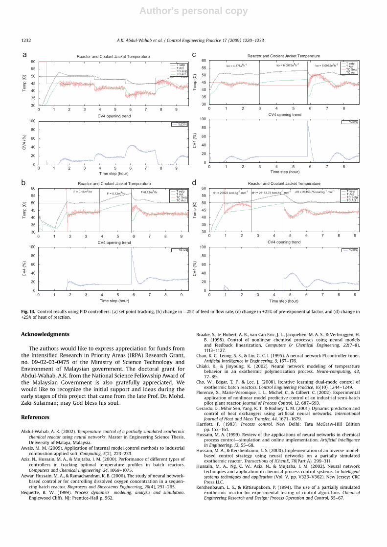
A comparison with the conventional cascade controllerwas also drawn in this study. The observed performance, as seenin Fig. 13, where the PID was tuned with a well-knownCohen–Coon tuning method indicated that the adaptive neuralnetwork control strategy performed with less steady state errorand overshoot and a quicker response time. In evaluating the PIDcontroller’s ability to reject the disturbances, the tuning
parameters in the controller are found to need to becontinuously re-tuned to achieve satisfactory controlperformance. The PID method’s results were comparable to theNNIMC method in some of the cases studied. However, someoscillations and offsets were still present after implementing theconventional PID control scheme. This can be seen in Fig. 13 andthe tabulated IAE values in Table 4.
7. Discussions and conclusions
This paper describes an innovative development of apartially simulated exothermic chemical reactor to test various
ARTICLE IN PRESS
0 1 2 3 4 5 630
35
40
45
50
55
60Reactor, Coolant Jacket and Feed Temperature
Tem
p (C
)
T setp T act TC setpTC act
0 1 2 3 4 5 60
20
40
60
80
100Coolant flowrate trend
Time step (hours)
FT4
(%)
%FT4
0 0.5 1 1.5 2 2.5 3 3.5 4 4.530
35
40
45
50
55
60Reactor and Coolant Jacket Temperature
Tem
p (C
)
F = 0.16m3/hr F = 0.12m3/hr T setp T act TC setpTC act
0 0.5 1 1.5 2 2.5 3 3.5 4 4.50
20
40
60
80
100Coolant flowrate trend
Time step (hours)
FT4
(%)
%FT4
F = 0.12m3/hr
Fig. 10. Load disturbance rejection results for: (a) NNIMC and (b) ANNIMC for changes in feed flow rate from nominal values to 120 l/h.
A.K. Abdul-Wahab et al. / Control Engineering Practice 17 (2009) 1220–1233 1229

Author's personal copy
conventional and neural network control strategies. In thisreactor, the heat generated from the assumed exothermic reactionwas simulated through the use of controlled steam flow rate intothe reactor. The temperature of the reactor was regulated by anexternal plate heat exchanger that cools the process fluid andrecycles it back to the reactor. A software interface was alsodeveloped to measure the online data, provide control action tothe control valve and implement various control strategies forthe reactor system. Neural network-based controllers were theadvanced control strategy used to control temperature of thereactor in this work. They avoided the hassle associated withconventional controllers such as periodic tuning. Adaptive
methods were also incorporated in this work to accommodateprocess condition changes. Tests involving set point tracking andvarious external and internal disturbance changes were carriedout to evaluate and to demonstrate the robustness of theadvanced controllers.
In the online test, the conventional control and neural networkcontrol schemes, i.e. neural network internal model-based andneural network adaptive control strategies, were implementedto control the temperature of the reactor in a cascadecontrol configuration. The performance of the controllers wasobserved to vary from one strategy to another. The adaptiveproperty introduced to the neural network-based control strategy
ARTICLE IN PRESS
0 0.5 1 1.5 2 2.5 3 3.5 4 4.530
35
40
45
50
55
60Reactor, Coolant Jacket and Feed Temperature
Tem
p (C
)
T setp T act TC setpTC act
0 0.5 1 1.5 2 2.5 3 3.5 4 4.50
20
40
60
80
100Coolant flowrate trend
Time step (hours)
FT4
(%)
%FT4
0 0.5 1 1.5 2 2.5 3 3.530
35
40
45
50
55
60Reactor, Coolant Jacket and Feed Temperature
Tem
p (C
)
dH=20923 kcal.kg-1.mol-1 dH = 26153.75 kcal.kg-1.mol-1 dH = 26153.75 kcal.kg-1.mol-1 T setp T act TC setpTC act
0 0.5 1 1.5 2 2.5 3 3.50
20
40
60
80
100Coolant flowrate trend
Time step (hours)
FT4
(%)
%FT4
Fig. 11. Load disturbance rejection results for: (a) NNIMC and (b) ANNIMC for changes in heat of reaction from nominal values to 2.615375�104 kcal/kg mol.
A.K. Abdul-Wahab et al. / Control Engineering Practice 17 (2009) 1220–12331230

Author's personal copy
contributed to enhancing the strength and reliability of the neuralnetwork controller performance. The adaptive neural networkcontroller, ANNIMC, was observed to significantly reduce theoffsets for both set point tracking and disturbance rejectionstudies compared to the other studied control strategies. Overall,good results were observed for the offsets and IAE values amongthese individual strategies. This adaptive strategy developed forthe study would be suitable for realistic industrial system whereoperating conditions are constantly changing. The performance ofthe neural network internal model-based control strategy wasfairly acceptable in controlling the temperature, however, some
offsets still persist. In comparison to the conventional PID method,the offsets were similar; in addition to the offsets, moreoscillations were observed using the PID method. In summary,the system developed in this study has enabled us to test variouscontrol strategies online under actual operating conditions.Simulations are not sufficient to validate controller performancein real and industrial-based implementation. Other advancedcontrol strategies such as the genetic algorithms, fuzzy logic andhybrid-based control schemes can also be implemented onlinewith the user-friendly tools shown here and shows promisingdirection for future work.
ARTICLE IN PRESS
0 0.5 1 1.5 2 2.530
35
40
45
50
55
60Reactor, Coolant Jacket and Feed Temperature
Tem
p (C
)
T setp T act TC setpTC act
0 0.5 1 1.5 2 2.50
20
40
60
80
100Coolant flowrate trend
Time step (hours)
FT4
(%)
%FT4
0 0.5 1 1.5 2 2.5 330
35
40
45
50
55
60Reactor, Coolant Jacket and Feed Temperature
Tem
p (C
)
T setp T act TC setpTC act
0 0.5 1 1.5 2 2.5 30
20
40
60
80
100Coolant flowrate trend
Time step (hours)
FT4
(%)
%FT4
ko = 4878000 h-1 ko = 6097500 h-1ko = 6097500 h-1
Fig. 12. Load disturbance rejection results for: (a) NNIMC and (b) ANNIMC for changes in pre-exponential factor from nominal values to 6.0975�106 h�1.
A.K. Abdul-Wahab et al. / Control Engineering Practice 17 (2009) 1220–1233 1231
Author's personal copy
Acknowledgments
The authors would like to express appreciation for funds fromthe Intensified Research in Priority Areas (IRPA) Research Grant,no. 09-02-03-0475 of the Ministry of Science Technology andEnvironment of Malaysian government. The doctoral grant forAbdul-Wahab, A.K. from the National Science Fellowship Award ofthe Malaysian Government is also gratefully appreciated. Wewould like to recognize the initial support and ideas during theearly stages of this project that came from the late Prof. Dr. Mohd.Zaki Sulaiman; may God bless his soul.
References
Abdul-Wahab, A. K. (2002). Temperature control of a partially simulated exothermic
chemical reactor using neural networks. Master in Engineering Science Thesis,
University of Malaya, Malaysia.
Awais, M. M. (2005). Application of internal model control methods to industrial
combustion applied soft. Computing, 5(2), 223–233.
Aziz, N., Hussain, M. A., & Mujtaba, I. M. (2000). Performance of different types of
controllers in tracking optimal temperature profiles in batch reactors.
Computers and Chemical Engineering, 24, 1069–1075.
Azwar, Hussain, M. A., & Ramachandran, K. B. (2006). The study of neural network-
based controller for controlling dissolved oxygen concentration in a sequen-
cing batch reactor. Bioprocess and Biosystems Engineering, 28(4), 251–265.
Bequette, B. W. (1999). Process dynamics—modeling, analysis and simulation.
Englewood Cliffs, NJ: Prentice-Hall p. 562.
Braake, S., te Hubert, A. B., van Can Eric, J. L., Jacquelien, M. A. S., & Verbruggen, H.B. (1998). Control of nonlinear chemical processes using neural modelsand feedback linearization. Computers & Chemical Engineering, 22(7–8),1113–1127.
Chan, K. C., Leong, S. S., & Lin, G. C. I. (1995). A neural network PI controller tuner.Artificial Intelligence in Engineering, 9, 167–176.
Chiaki, K., & Jinyoung, K. (2002). Neural network modeling of temperaturebehavior in an exothermic polymerization process. Neuro-computing, 43,77–89.
Cho, W., Edgar, T. F., & Lee, J. (2008). Iterative learning dual-mode control ofexothermic batch reactors. Control Engineering Practice, 16(10), 1244–1249.
Florence, X., Marie-Veronique, L. L., Michel, C., & Gilbert, C. (2002). Experimentalapplication of nonlinear model predictive control of an industrial semi-batchpilot plant reactor. Journal of Process Control, 12, 687–693.
Gerardo, D., Mihir Sen, Yang, K. T., & Rodney, L. M. (2001). Dynamic prediction andcontrol of heat exchangers using artificial neural networks. InternationalJournal of Heat and Mass Transfer, 44, 1671–1679.
Harriott, P. (1983). Process control. New Delhi: Tata McGraw-Hill Editionpp. 153–161.
Hussain, M. A. (1999). Review of the applications of neural networks in chemicalprocess control—simulation and online implementation. Artificial Intelligencein Engineering, 13, 55–68.
Hussain, M. A., & Kershenbaum, L. S. (2000). Implementation of an inverse-model-based control strategy using neural networks on a partially simulatedexothermic reactor. Transactions of IChemE, 78(Part A), 299–311.
Hussain, M. A., Ng, C. W., Aziz, N., & Mujtaba, I. M. (2002). Neural networktechniques and application in chemical process control systems. In Intelligentsystems techniques and application (Vol. V, pp. V326–V362). New Jersey: CRCPress LLC.
Kershenbaum, L. S., & Kittisupakorn, P. (1994). The use of a partially simulatedexothermic reactor for experimental testing of control algorithms. ChemicalEngineering Research and Design: Process Operation and Control, 55–67.
ARTICLE IN PRESS
0 1 2 3 4 5 6 7 8 930
35
40
45
50
55
60Reactor and Coolant Jacket Temperature
Tem
p (C
)
T setpT ActTC setpTC act
0 1 2 3 4 5 6 7 8 90
20
40
60
80
100CV4 opening trend
Time step (hour)
CV
4 (%
)
%CV4
0 1 2 3 4 5 6 7 8 930
35
40
45
50
55
60Reactor and Coolant Jacket Temperature
Tem
p (C
)
F = 0.12m3/hrT setp T Act TC SetpTC Act
0 1 2 3 4 5 6 7 8 90
20
40
60
80
100CV4 opening trend
Time step (hour)
CV
4 (%
)
%CV4
F = 0.16m3/hr F=0.12m3/hr
0 1 2 3 4 5 6 7 830
35
40
45
50
55
60Reactor and Coolant Jacket Temperature
Tem
p (C
)
ko = 4.878e6h-1 ko = 6.0975e6h-1 ko = 6.0975e6h-1 T setp T Act TC SetpTC Act
0 1 2 3 4 5 6 7 80
20
40
60
80
100CV4 opening trend
Time step (hour)
CV
4 (%
)
%CV4
0 1 2 3 4 5 6 7 8 930
35
40
45
50
55
60Reactor and Coolant Jacket Temperature
Tem
p (C
)dH = 29023 kcal.kg-1.mol-1 dH = 26153.75 kcal.kg-1.mol-1 dH = 26153.75 kcal.kg-1.mol-1 T setp
T Act TC SetpTC Act
0 1 2 3 4 5 6 7 8 90
20
40
60
80
100CV4 opening trend
Time step (hour)
CV
4 (%
)
%CV4
Fig. 13. Control results using PID controllers: (a) set point tracking, (b) change in �25% of feed in flow rate, (c) change in +25% of pre-exponential factor, and (d) change in
+25% of heat of reaction.
A.K. Abdul-Wahab et al. / Control Engineering Practice 17 (2009) 1220–12331232

Author's personal copy
Lennox, B., Montaque, G. A., Frith, A. M., Gent, C., & Bevan, V. (2001). Industrial applicationof neural networks—an investigation. Journal of Process Control, 11, 497–507.
Marlin, T. E. (1995). Process control, designing processes and control systems fordynamic performances (International ed.). New York: McGraw-Hill pp. 242–243.
Mujtaba, I. M., Aziz, N., & Hussain, M. A. (2006). Neural network based modelingand control in batch reactor. Transactions of IChemE, Part A, ChemicalEngineering Research and Design, 84(A8), 635–644.
Mujtaba, I. M., & Hussain, M. A. (1998). Optimal operation of dynamic processesunder process-model mismatches: Application to batch distillation. Computers& Chemical Engineering, 22(Suppl.), S621–S624.
Nikravesh, M., Farell, A. E., & Stanford, T. G. (2000). Control of nonisothermal CSTRwith time varying parameters via dynamic neural network control (DNNC).Chemical Engineering Journal, 78, 1–16.
Nougues, J. M., Pan, Y. G., Velo, E., & Puigjaner, L. (2000). Identification of a pilotscale fluidised-bed coal gasification unit by using neural networks. AppliedThermal Engineering, 20, 1561–1575.
Pham, D. T., & Oh, S. J. (1999). Identification of plant inverse dynamics using neuralnetworks. Artificial Intelligence in Engineering, 13, 309–320.
Radhakrishnan, V. R., & Mohamed, A. R. (2000). Neural networks for theidentification and control of blast furnace hot metal quality. Journal of ProcessControl, 10, 509–524.
Rogers, G. F. C., & Mayhew, Y. R. (1981). Thermodynamic and transport properties offluids, SI Units (third ed). Oxford: Basil Blackwell.
Saha, P. K., Shoib, M., & Kamruzzaman, J. (1998). Development of a neural networkbased integrated control system of 120-ton/h capacity boiler. Computers andElectrical Engineering, 24, 423–440.
Wachira, D., Piyanuch, T., Amornchai, A., Paisan, K., & Hussain, M. A. (2005). Neuralnetwork inverse model-based controller for the control of a steel picklingprocess. Computers & Chemical Engineering, 29, 2110–2119.
Yu, D. L., & Gomm, J. B. (2003). Implementation of neural network predictivecontrol to a multivariable chemical reactor. Control Engineering Practice, 11,1315–1323.
ARTICLE IN PRESS
A.K. Abdul-Wahab et al. / Control Engineering Practice 17 (2009) 1220–1233 1233