author's personal copy - shahid chamran university of...
TRANSCRIPT

This article appeared in a journal published by Elsevier. The attachedcopy is furnished to the author for internal non-commercial researchand education use, including for instruction at the authors institution
and sharing with colleagues.
Other uses, including reproduction and distribution, or selling orlicensing copies, or posting to personal, institutional or third party
websites are prohibited.
In most cases authors are permitted to post their version of thearticle (e.g. in Word or Tex form) to their personal website orinstitutional repository. Authors requiring further information
regarding Elsevier’s archiving and manuscript policies areencouraged to visit:
http://www.elsevier.com/copyright

Author's personal copy
Electric Power Systems Research 79 (2009) 107–116
Contents lists available at ScienceDirect
Electric Power Systems Research
journa l homepage: www.e lsev ier .com/ locate /epsr
Harmonic estimation in a power system using a novel hybrid LeastSquares-Adaline algorithm
M. Joorabian1, S.S. Mortazavi, A.A. Khayyami ∗
Electrical Engineering Department, Shahid Chamran University, Ahwaz, 61355, Iran
a r t i c l e i n f o
Article history:Received 30 May 2006Received in revised form 7 May 2008Accepted 23 May 2008Available online 14 July 2008
Keywords:Harmonic estimationHybrid algorithmLeast squares (LS)Adaptive linear combinerAdalineNeural networksAdaptive Kalman filter
a b s t r a c t
Nowadays many algorithms have been proposed for harmonic estimation in a power system. Most of themdeal with this estimation as a totally nonlinear problem. Consequently, these methods either convergeslowly, like GA algorithm [U. Qidwai, M. Bettayeb, GA based nonlinear harmonic estimation, IEEE Trans.Power Delivery (December) 1998], or need accurate parameter adjustment to track dynamic and abruptchanges of harmonics amplitudes, like adaptive Kalman filter (KF) [Steven Liu, An adaptive Kalman filterfor dynamic estimation of harmonic signals, in: 8th International Conference On Harmonics and Qualityof Power, ICHQP’98, Athens, Greece, October 14–16, 1998]. In this paper a novel hybrid approach, based onthe decomposition of the problem into a linear and a nonlinear problem, is proposed. A linear estimator,i.e., Least Squares (LS), which is simple, fast and does not need any parameter tuning to follow harmonicsamplitude changes, is used for amplitude estimation and an adaptive linear combiner called ‘Adaline’,which is very fast and very simple is used to estimate phases of harmonics. An improvement in convergenceand processing time is achieved using this algorithm. Moreover, better performance in online tracking ofdynamic and abrupt changes of signals is the result of applying this method.
© 2008 Elsevier B.V. All rights reserved.
1. Introduction
The wide spreading applications of electronically controlledloads have increased the harmonic distortion in power systemvoltage and current waveforms. As power semiconductors areswitched on and off at different points on the voltage wave-form, damped high-frequency transients are generated. If switchingoccurs at the same points on each cycle, the transient becomesperiodic. This transient whose frequency is not a multiple of fun-damental frequency is non-stationary [1]; consequently, voltageand current waveforms of a distribution or a transmission sys-tem are not pure sinusoids, but may consist of a combinationof the fundamental frequency, harmonics, and high-frequencytransients. Furthermore, many of power system loads, especiallyindustrial loads, are dynamic in nature, which implies time-varying amplitude of the current waveforms. For example, loadsthat exhibit a sequential starting and braking operations gen-erate time-varying current amplitude. The rate of change ofthe current amplitude depends on the type and size of load[1].
∗ Corresponding author. Fax: +98 611 3360017.E-mail addresses: [email protected] (M. Joorabian), mortazavi [email protected]
(S.S. Mortazavi), khayyami [email protected] (A.A. Khayyami).1 Tel. +98 916 118 3017.
In order to provide the quality of the delivered power, it is imper-ative to know the harmonics parameters such as magnitude andphase. This is essential for designing filter for eliminating or reduc-ing the effects of harmonics in a power system [2].
Many algorithms have been proposed to evaluate the harmon-ics [1,2,6–9], and [10]. To obtain the voltage and current frequencyspectrum from discrete time samples, most frequency domainharmonic analysis algorithms are based on the discrete FourierTransform (DFT) or on the fast Fourier transform (FFT) [1]. How-ever, these two methods suffer three pitfalls, namely, aliasing,leakage and picket-fence effect [1,4] and [5]. Although other meth-ods, including the proposed algorithm in this paper, suffer thesethree problems, and this is because of existing high-frequency com-ponents in the measured signal [1], however truncation of thesequence of sampled data, when only a fraction of the sequenceof a cycle exists in the analyzed waveform, can boost leakage prob-lem of DFT method. So the need for new algorithms that processthe data, sample-by-sample, and not a window of data as in FFTand DFT, is of paramount importance. Because these methods pro-cess data sample-by-sample, loosing one or more samples createsless leakage problems than FFT and DFT. One of these methods isKalman filter.
Using fixed gain Kalman filter, a more robust algorithm wasintroduced by Dash and Sharaf [6] for estimating the magni-tudes of sinusoids of known frequencies embedded in an unknownmeasurement noise which can be a mixture of both stochastic and
0378-7796/$ – see front matter © 2008 Elsevier B.V. All rights reserved.doi:10.1016/j.epsr.2008.05.021

Author's personal copy
108 M. Joorabian et al. / Electric Power Systems Research 79 (2009) 107–116
signals. But this algorithm cannot track abrupt or dynamic changesof signal and its harmonics.
Online tracking of harmonics in power systems using a variablegain Kalman filtering approach was described by Girgis et al. [1],which was still unable to track abrupt changes of signals. Later,an adaptive Kalman filtering approach was introduced by Liu [7]for dynamic estimation of harmonic signals. This adaptive tech-nique enabled Kalman filter to track dynamic and abrupt changesof harmonics amplitudes.
Recently developments of AI techniques have encouraged theresearchers to use these methods for harmonic estimation. Mori[8] used artificial neural network (based on back propagation learn-ing technique) for this purpose. A very simple algorithm based onan adaptive neural network was used by Dash et al. [2], whichdespite its simplicity shows results that are not only comparablewith classic Kalman filtering approach but are also better in trackingdynamic amplitudes.
Since estimation of harmonic parameters is actually a nonlinearproblem, genetic algorithm (GA), as a heuristic and stochastic globalsearching algorithm was used by Qidwai and Betayeb [9] for thispurpose. In spite of ease of use and excellent results that have beenobtained by this method, some disadvantages are observed in thismethod [10]:
1. Time needed for convergence is large, specially when estimatingmultiple frequency components (n) because of large number ofparameters (2n) that had to be identified.
2. Due to the existence of a large number of parameters, more com-binations of final convergence exist. This requires more insightinto the system structure.
3. Since amplitudes and phases are different quantitatively withdifferent scales, units, and physical interpretation, it is difficultto get the homogenous genetic pool with respect to the finalsolution. One way could be normalizing both parameters, whicheven then, the magnitudes of phases and amplitudes would liein very different regions on the number line.
2. Proposed algorithm
All the above problems come from nonlinearity in harmonicestimation. However, in this paper a hybrid algorithm for harmonicestimation is proposed. The idea is based on a new look at assumedsignal structure [2,9] and [10]:
Z(t) =N∑
n=1
An sin(ωnt + ϕn) + ADC exp(−˛DCt) + v(t) (1)
where N is the number of harmonics; ωn = n2�f0; f0 is the funda-mental frequency; v(t) the additive noise; and ADC exp(−˛DCt) isthe probable decaying term.
The discrete time version of Eq. (1) can be represented as:
Z(k) =N∑
n=1
An sin(ωnkTs + ϕn) + ADC exp(−˛DCkTs) + v(k) (2)
where Ts is sampling period.Approximating decaying term using first two terms of Taylor
series as:
ydc = ADC − ADC˛DCkTs (3)
will result in:
Z(k) =N∑
n=1
An sin(ωnkTs + ϕn) + ADC − ADC˛DCkTs + v(k) (4)
As can be seen the only nonlinearity that exists in the modelis due to the phase of sinusoids. Therefore, the problem ofestimating harmonic parameters (i.e., harmonic amplitudes andphases) can be decomposed in two parts: linear and nonlin-ear. In linear section, amplitudes are estimated using a linearestimator like Least Squares (LS) algorithm. The advantage ofLS is that despite other methods like KF approach, it doesnot need any parameter tuning for tracking abrupt or dynamicchanges of harmonics amplitudes. In nonlinear section, using anonlinear estimator, phases are estimated. Bettayeb and Qidwaiused GA for this goal. Although using GA for estimating phasesalleviated mentioned problems, but because of GA, the overallalgorithm is still slow; and cannot be used as an online estima-tor.
In this paper, for estimation of phases, the use of a simple andfast neural network, called Adaline, which can estimate phases veryfast, is proposed. Consequently, in brief the proposed algorithm willbe as follows:
In each iteration the phases are estimated using Adaline net-work. Then, they are used to estimate the amplitudes with usual LSalgorithm.
2.1. Amplitude estimation using LS
The resulting sampled linear model of the system with additivenoise in (4) can be rewritten as follows:
Z(k) = H(k)�(k) + v(k) (5)
where Z(k) is the noisy measurement; H(k) the system structurematrix; �(k) the vector of amplitudes that should be estimated;v(k) is the additive noise.
The estimation model for this system is�Z(k) = H(k)
��(k) (6)
The estimate��(k) for the requested parameters �(k) can be
obtained by minimizing the objective function
J[��(k)] = Z̃
T(k)Z̃(k) (7)
where Z̃(k) represents the error of estimation with respect to themeasured values. Differentiation with respect to �(k) and then set-ting it to zero gives the required LS estimation algorithm:��LS(k) = [HT(k)H(k)]
−1H(k)Z(k) (8)
The system structure matrix H(k) is given by
H(k) =
⎡⎢⎣
sin(ω1t1 + ϕ1) sin(ω2t1 + ϕ2) . . . sin(ωN t1 + ϕN ) 1 −t1
sin(ω1t2 + ϕ1) sin(ω2t2 + ϕ2) . . . sin(ωN t2 + ϕN ) 1 −t2
.
.
....
.
.
....
.
.
....
sin(ω1tk + ϕ1) sin(ω2tk + ϕ2) . . . sin(ωN tk + ϕN ) 1 −tk
⎤⎥⎦
(9)
where phases are estimated from Adaline. Using this structurematrix with the sampled values in (2) would give the estimatesfor amplitudes vector.
�(k) = [ A1(k) A2(k) . . . AN(k) ADC ADC˛DC ]T (10)
2.2. Estimation of phases using Adaline
To estimate phases, Eq. (4) can be rewritten as follows:
Z(k) =N∑
n=1
[An sin(ωnkTs) cos ϕn + An cos(ωnkTs) sin ϕn]
+ADC − ADC˛DCkTs + v(k) (11)
Author's personal copy
M. Joorabian et al. / Electric Power Systems Research 79 (2009) 107–116 109
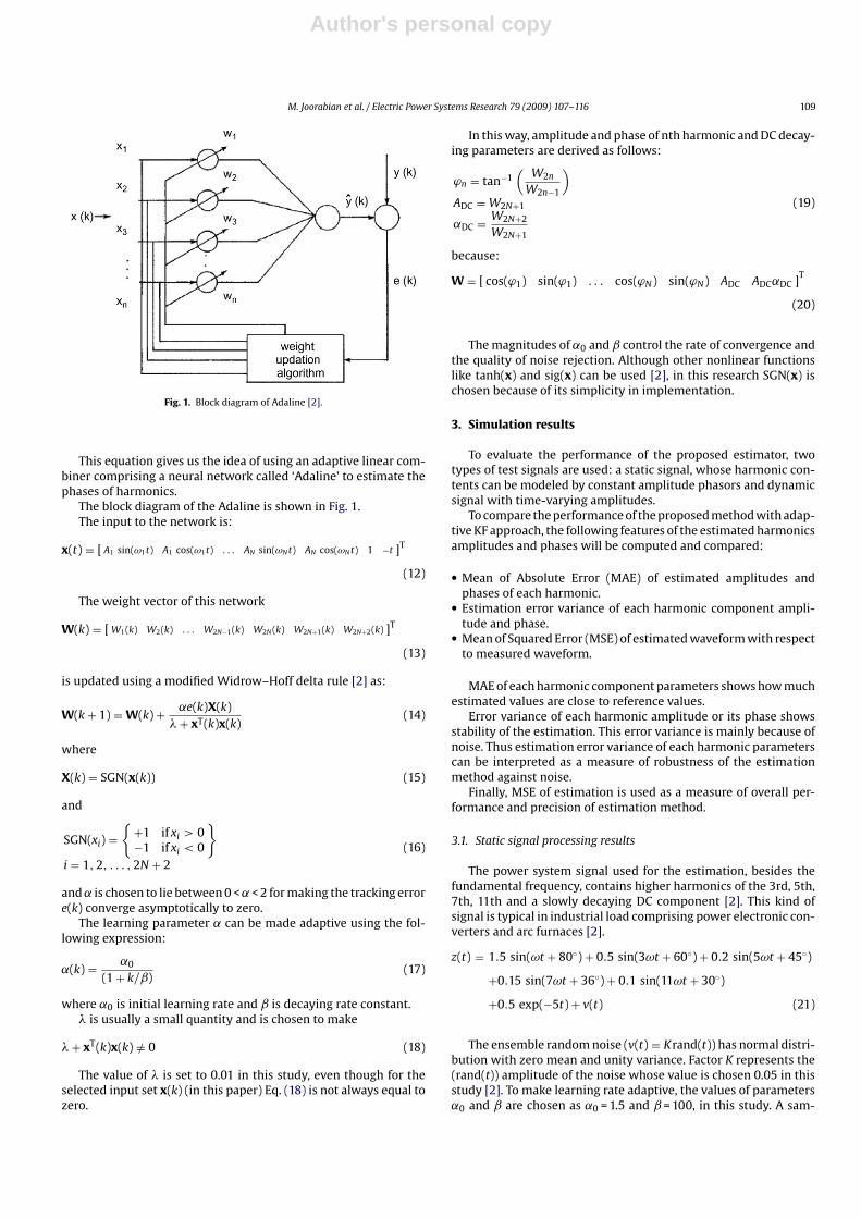
Fig. 1. Block diagram of Adaline [2].
This equation gives us the idea of using an adaptive linear com-biner comprising a neural network called ‘Adaline’ to estimate thephases of harmonics.
The block diagram of the Adaline is shown in Fig. 1.The input to the network is:
x(t) = [ A1 sin(ω1t) A1 cos(ω1t) . . . AN sin(ωN t) AN cos(ωN t) 1 −t ]T
(12)
The weight vector of this network
W(k) = [ W1(k) W2(k) . . . W2N−1(k) W2N (k) W2N+1(k) W2N+2(k) ]T
(13)
is updated using a modified Widrow–Hoff delta rule [2] as:
W(k + 1) = W(k) + ˛e(k)X(k)� + xT(k)x(k)
(14)
where
X(k) = SGN(x(k)) (15)
and
SGN(xi) ={
+1 if xi > 0−1 if xi < 0
}
i = 1, 2, . . . , 2N + 2(16)
and ˛ is chosen to lie between 0 < ˛ < 2 for making the tracking errore(k) converge asymptotically to zero.
The learning parameter ˛ can be made adaptive using the fol-lowing expression:
˛(k) = ˛0
(1 + k/ˇ)(17)
where ˛0 is initial learning rate and ˇ is decaying rate constant.� is usually a small quantity and is chosen to make
� + xT(k)x(k) /= 0 (18)
The value of � is set to 0.01 in this study, even though for theselected input set x(k) (in this paper) Eq. (18) is not always equal tozero.
In this way, amplitude and phase of nth harmonic and DC decay-ing parameters are derived as follows:
ϕn = tan−1(
W2n
W2n−1
)ADC = W2N+1
˛DC = W2N+2
W2N+1
(19)
because:
W = [ cos(ϕ1) sin(ϕ1) . . . cos(ϕN) sin(ϕN) ADC ADC˛DC ]T
(20)
The magnitudes of ˛0 and ˇ control the rate of convergence andthe quality of noise rejection. Although other nonlinear functionslike tanh(x) and sig(x) can be used [2], in this research SGN(x) ischosen because of its simplicity in implementation.
3. Simulation results
To evaluate the performance of the proposed estimator, twotypes of test signals are used: a static signal, whose harmonic con-tents can be modeled by constant amplitude phasors and dynamicsignal with time-varying amplitudes.
To compare the performance of the proposed method with adap-tive KF approach, the following features of the estimated harmonicsamplitudes and phases will be computed and compared:
• Mean of Absolute Error (MAE) of estimated amplitudes andphases of each harmonic.
• Estimation error variance of each harmonic component ampli-tude and phase.
• Mean of Squared Error (MSE) of estimated waveform with respectto measured waveform.
MAE of each harmonic component parameters shows how muchestimated values are close to reference values.
Error variance of each harmonic amplitude or its phase showsstability of the estimation. This error variance is mainly because ofnoise. Thus estimation error variance of each harmonic parameterscan be interpreted as a measure of robustness of the estimationmethod against noise.
Finally, MSE of estimation is used as a measure of overall per-formance and precision of estimation method.
3.1. Static signal processing results
The power system signal used for the estimation, besides thefundamental frequency, contains higher harmonics of the 3rd, 5th,7th, 11th and a slowly decaying DC component [2]. This kind ofsignal is typical in industrial load comprising power electronic con-verters and arc furnaces [2].
z(t) = 1.5 sin(ωt + 80◦) + 0.5 sin(3ωt + 60◦) + 0.2 sin(5ωt + 45◦)
+0.15 sin(7ωt + 36◦) + 0.1 sin(11ωt + 30◦)
+0.5 exp(−5t) + v(t) (21)
The ensemble random noise (v(t) = Krand(t)) has normal distri-bution with zero mean and unity variance. Factor K represents the(rand(t)) amplitude of the noise whose value is chosen 0.05 in thisstudy [2]. To make learning rate adaptive, the values of parameters˛0 and ˇ are chosen as ˛0 = 1.5 and ˇ = 100, in this study. A sam-

Author's personal copy
110 M. Joorabian et al. / Electric Power Systems Research 79 (2009) 107–116
Fig. 2. Tracking the 5th harmonic’s parameters using LS-Adaline.
pling rate of 32 samples per cycle on a 50 Hz waveforms is used fornumerical computation.
Fig. 2 represents results of estimation for harmonic parametersof 5th harmonic parameters. Other estimated harmonic parame-ters using the proposed method follow almost the same trackingbehavior and converge to their corresponding reference valuesafter about one cycle. Fig. 3 shows the signal under process (mea-sured signal or simulated signal) and the estimated signal builtusing estimated harmonic parameters. In other words, this fig-ure represents the overall tracking quality of the method. Fig. 4shows the error of this tracking. As a measure of performanceof the proposed algorithm and its robustness in rejecting noise,the results of estimation of Kalman filtering approach for the 5thharmonic component is represented in Fig. 5. Other componentshave almost the same tracking criteria with higher variation intheir estimated values for higher orders of harmonics. Fig. 6 illus-trates error of tracking for KF approach. The KF is tuned optimallyby properly choosing the covariance and noise variance values[7].
To compare these two methods, some numerical performanceindices, as were described earlier, are computed for both methods.
Fig. 3. Measured and estimated waveforms using LS-Adaline.
Fig. 4. Estimation error of LS-Adaline.
Fig. 5. Tracking the 5th harmonic’s parameters using adaptive KF.
Fig. 6. Error of estimation using adaptive KF.

Author's personal copy
M. Joorabian et al. / Electric Power Systems Research 79 (2009) 107–116 111
Table 1MAE of amplitudes
Harmonic order LS-Adaline Adaptive KF
1st 0.0005 0.00163rd 0.0031 0.00565th 0.0013 0.00307th 0.0016 0.003611th 0.0021 0.0044
Table 2MAE of phases
Harmonic order LS-Adaline Adaptive KF
1st 0.0581 0.07713rd 0.3961 0.68935th 0.7952 1.58857th 0.7919 1.178611th 0.3207 1.0725
Table 3Variance of amplitudes
Harmonic order LS-Adaline Adaptive KF
1st 0.0017 × 10⁻⁴ 0.0298 × 10⁻⁴
3rd 0.0461 × 10⁻⁴ 0.1070 × 10⁻⁴
5th 0.0207 × 10⁻⁴ 0.1060 × 10⁻⁴
7th 0.0264 × 10⁻⁴ 0.1467 × 10⁻⁴
11th 0.0066 × 10⁻⁴ 0.0767 × 10⁻⁴
Table 4Variance of phases
Harmonic order LS-Adaline Adaptive KF
1st 0.0038 0.01173rd 0.0370 0.08505th 0.0391 0.72387th 0.0145 0.265111th 0.1457 1.6579
The starting point of computation of these indices is the beginningof the second cycle. Results are represented in Tables 1–5.
As can bee seen in Figs. 2–6, both methods converge to referencevalues approximately after one cycle. But Tables 1, 2 and 5 showthat the proposed method estimates harmonics parameters andthe signal under process more precisely. Moreover, Tables 3 and 4reveal that LS-Adaline makes this estimation with less variation.As it was explained earlier, this can be interpreted as better robust-ness against noise. On the other hand, although adapting KF needstuning four free parameters [7], only two parameters have to beadjusted in LS-Adaline.
3.2. Harmonic tracking in faulted power systems
To test the performance of proposed algorithm in tracking time-varying harmonic components of a faulty transmission system, itis applied to a simulation of a single-line-to-ground fault on theA-phase of a transmission line [2]. Bear in mind that abrupt changeof current is exaggerated for showing excellent capabilities of LS-Adaline method. The chosen values for ˛0 and ˇ are ˛0 = 1.1 andˇ = 100.
Table 5MSE of estimation
LS-Adaline Adaptive KF
0.0004 0.0026
Fig. 7. Tracking the 3rd harmonic’s parameters using LS-Adaline.
Table 6MAE of amplitudes
Harmonic order LS-Adaline Adaptive KF
1st 0.0011 0.00293rd 0.0026 0.00395th 0.0033 0.00697th 0.0011 0.001311th 0.0006 0.0010
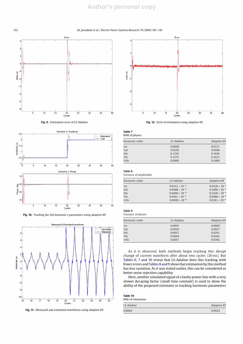
Here again the estimation results of the proposed algorithm arecompared with the adaptive KF approach, which is tuned optimallyby properly choosing the covariance and noise variance values [7].Because in each method, tracking behavior for all harmonic compo-nents is almost the same, only tracking of 3rd harmonic parametersis illustrated here; Figs. 7 and 10.
Figs. 8 and 11 show how the measured signal is tracked by bothestimation methods above. Figs. 9 and 12 display overall trackingerror of these two methods.
Computed performance indices for both methods are gatheredin Tables 6–10. The starting point of computation of these indicesis the beginning of the third cycle after occurrence of the fault.
Fig. 8. Measured and estimated waveforms using LS-Adaline.
Author's personal copy
112 M. Joorabian et al. / Electric Power Systems Research 79 (2009) 107–116
Fig. 9. Estimation error of LS-Adaline.
Fig. 10. Tracking the 3rd harmonic’s parameters using adaptive KF.
Fig. 11. Measured and estimated waveforms using adaptive KF.
Fig. 12. Error of estimation using adaptive KF.
Table 7MAE of phases
Harmonic order LS-Adaline Adaptive KF
1st 0.0058 0.01133rd 0.0350 0.05065th 0.1336 0.16367th 0.1275 0.162311th 0.0969 0.2469
Table 8Variance of amplitudes
Harmonic order LS-Adaline Adaptive KF
1st 0.0212 × 10⁻⁴ 0.0328 × 10⁻⁴
3rd 0.0408 × 10⁻⁴ 0.1606 × 10⁻⁴
5th 0.0406 × 10⁻⁴ 0.3320 × 10⁻⁴
7th 0.0101 × 10⁻⁴ 0.0480 × 10⁻⁴
11th 0.0009 × 10⁻⁴ 0.0181 × 10⁻⁴
Table 9Variance of phases
Harmonic order LS-Adaline Adaptive KF
1st 0.0001 0.00023rd 0.0020 0.00275th 0.0057 0.02917th 0.0094 0.016411th 0.0057 0.0392
As it is observed, both methods begin tracking this abruptchange of current waveform after about two cycles (20 ms). ButTables 6, 7 and 10 reveal that LS-Adaline does this tracking withfewer errors and Tables 8 and 9 show that estimation by this methodhas less variation. As it was stated earlier, this can be considered asbetter noise rejection capability.
Here, another simulated signal of a faulty power line with a veryslower decaying factor (small time constant) is used to show theability of the proposed estimator in tracking harmonic parameters
Table 10MSE of estimation
LS-Adaline Adaptive KF
0.0004 0.0024

Author's personal copy
M. Joorabian et al. / Electric Power Systems Research 79 (2009) 107–116 113
Fig. 13. Tracking the 3rd harmonic’s parameters using LS-Adaline.
in such cases. Fig. 13 shows the quality of this tracking for 3rd com-ponent. Other components have almost the same scheme. Fig. 14illustrates the measured (simulated) signal and the estimated sig-nal in one figure, to show the quality of overall tracking and Fig. 15shows the tracking error. These two figures reveal how well theproposed algorithm tracks the signal in this condition. Since herethe changes of the signal are slow, the estimator can follow changesalmost without considerable delay.
3.3. Harmonic estimation of a dynamic signal
To examine the performance of LS-Adaline algorithm in track-ing harmonics and its robustness in rejecting noise, a time-varyingsignal of the form [2]:
z(t) = {1.5 + a1(t)} sin(ω0t + 800) + {0.5 + a3(t)} sin(3ω0t + 60◦)
+ {0.2 + a5(t)} sin(5ω0t + 45◦) + v(t) (22)
is used where:
a1 = 0.15 sin 2�f1t + 0.05 sin 2�f5ta3 = 0.05 sin 2�f3t + 0.02 sin 2�f5ta5 = 0.025 sin 2�f1t + 0.005 sin 2�f5t
Fig. 14. Measured and estimated waveforms using LS-Adaline.
Fig. 15. Estimation error of LS-Adaline.
Table 11MAE of amplitudes
Harmonic order LS-Adaline Adaptive KF
1st 0.0112 0.01603rd 0.0082 0.01285th 0.0067 0.0242
and
f1 = 1.0 Hz, f3 = 3.0 Hz, f5 = 6.0 Hz
and the random noise v(t) is the same as in previous static signal.The values of ˛0 and ˇ are chosen as ˛0 = 1.1 and ˇ = 100.
Fig. 16 shows the signal waveform and Fig. 17 illustrates track-ing of the 3rd harmonic parameters using LS-Adaline. Estimationof other harmonics follows the same scheme, so they are not rep-resented here. Fig. 18 represents tracking error of the method. Liketwo previous cases the results of the harmonic estimation of thesame waveform using adaptive KF are represented in Figs. 19 and 20.For better comparison, computed performance indices are repre-sented in Tables 11–15.
Fig. 16. Dynamic signal (50 cycles).

Author's personal copy
114 M. Joorabian et al. / Electric Power Systems Research 79 (2009) 107–116
Fig. 17. Tracking the 3rd harmonic’s parameters using LS-Adaline.
Fig. 18. Estimation error of LS-Adaline.
Fig. 19. Tracking the 3rd harmonic’s parameters using adaptive KF.
Fig. 20. Estimation error of adaptive KF.
Table 12MAE of phases
Harmonic order LS-Adaline Adaptive KF
1st 0.0816 0.60193rd 0.3875 1.50395th 1.1541 4.5397
Table 13Variance of amplitudes
Harmonic order LS-Adaline Adaptive KF
1st 0.1904 × 10⁻³ 0.4303 × 10⁻³
3rd 0.1097 × 10⁻³ 0.2628 × 10⁻³
5th 0.0691 × 10⁻³ 0.8019 × 10⁻³
Table 14Variance of phases
Harmonic order LS-Adaline Adaptive KF
1st 0.0125 0.50683rd 0.0265 3.48145th 1.2591 32.0498
Comparing the two methods shows that where LS-Adalinebegins tracking dynamic parameters of harmonics after elapsingonly one cycle (20 ms), adaptive KF needs more than two cyclesfor this goal. Contents of Tables 11, 12 and 15 prove the preci-sion of the proposed algorithm in comparison with adaptive KF.Tables 13 and 14 indicate better and excellent performance ofLS-Adaline in rejecting noise, especially for estimation the 5th har-monic.
3.4. Effects of frequency drift on harmonic estimation
The effects of frequency drift on the estimation of harmon-ics components in the presence of random noise (k = 0.05) [2] arestudied and represented. Here, a large value for frequency drift:
Table 15MSE of estimation
LS-Adaline Adaptive KF
0.0016 0.0024

Author's personal copy
M. Joorabian et al. / Electric Power Systems Research 79 (2009) 107–116 115
Fig. 21. Effects of frequency drift on harmonic tracking of 7th component.
�f = −1 Hz [2] at the 10th cycle is considered and is restored to itsoriginal value, 50 Hz, at 12th cycle.
Figs. 21–23 show the results for 7th and 11th components andan overall error. As it is observed, a −1 Hz frequency drift makes anoscillation in the estimation of amplitudes and phases. However,they are restored to the original values only one cycle after thefrequency restoration. For a small frequency drift of 0.1 Hz, or less,the estimator does not show considerable variations.
4. Discussion
For adapting KF algorithm to dynamic and abrupt changes ofthe signal under consideration, four parameters should be tuned[7]. Furthermore, KF is designed for handling signals, which arepolluted with only white noise. GA, as another approach, convergesslowly and could not be used as a real time estimator, even whenit is used only for phase estimation [10].
All the above-mentioned problems are alleviated by proposedalgorithm. First, because LS algorithm dose not need any adaptationand tuning for tracking dynamic and abrupt changes of harmonicsamplitudes, only two parameters, i.e., ˛0 and ˇ should be adjusted.
Fig. 22. Effects of frequency drift on harmonic tracking of 11th component.
Fig. 23. Effects of frequency drift on harmonic tracking overall error.
Table 16Average processing time
No. of components LS-Adaline Adaptive KF
5 0.212 × 10⁻³ s 0.392 × 10⁻³ s20 0.227 × 10⁻³ s 0.413 × 10⁻³ s
s: seconds.
Second, the proposed algorithm is a composition of a very sim-ple and consequently very fast neural network, i.e., Adaline, whichis composed of only one neuron, and a fast and simple linearalgorithm (LS algorithm). Comparing the necessary equations foradaptive KF algorithm [7] with equations of proposed method, Eqs.(8) and (14) reveals the reason of the difference, too. Indeed LS-Aaline needs less computational efforts than adaptive KF. So, for thesame number of harmonic components, the proposed algorithmwill be faster. As a measure for comparison, the average process-ing time of each sample data for estimation of 5 and 20 harmoniccomponents was computed. The under processing signal was adynamic signal and the computation of processing time was doneusing instructions of MATLAB software. The used PC had a 2.4 GHzCPU and 256 MB RAM. The result is represented in Table 16, whichverifies that the proposed method is faster than adaptive KF. Third,Unlike KF which is restricted to handle only Gaussian noise, neitherLS algorithm nor Adaline method is restricted to any specific typeof noise. Therefore, it is supposed that the proposed method showsthe same performance in rejecting other noise types.
Furthermore, although the selected area of application is powersystems, the same algorithm can be applied to other types of signalsfrom communication channels, telephones, and other encryptedsignals.
5. Conclusion
A new hybrid LS-Adaline algorithm for estimation of harmonicparameters in a power system, which is essential for designing fil-ters, like the one that is presented in [3], for eliminating or reducingthe effects of harmonics in a power system, has been presented inthis paper. The new approach is based on the uncoupling the prob-lem into a linear and a nonlinear section. The linear part utilizesordinary least squares method to estimate amplitudes of harmonicsand the nonlinear section uses an Adaline network for estimat-ing phases of harmonics. Comparing with adaptive KF, simulation
Author's personal copy
116 M. Joorabian et al. / Electric Power Systems Research 79 (2009) 107–116
results reveal improvement in the performance of the proposed LS-Adaline in tracking harmonic parameters, even in the presence ofwhite noise and decaying DC component.
Appendix A. List of symbols
ADC exp(−˛DCt) probable decaying term of the signalAn nth harmonic amplitudee(k) tracking errorf0 fundamental frequencyH(k) system structure matrixk discrete time (sampling) indexTs sampling periodv(t) additive noiseW(k) weight vector of the Adalinex(k) input vector to the AdalineZ(k) noisy measurement�Z(k) estimated signalZ̃(k) error of estimation
Greek symbols˛DC decaying rate of decaying term˛ learning parameter of the Adaline˛0 initial learning rate of the Adalineˇ decaying rate constant of the Adalineϕn nth harmonic phase�(k) vector of amplitudes that should be estimated��(k) estimate of �(k)��LS(k) LS estimation of �(k)ωn n2�f0
References
[1] A.A. Girgis, W.B. Chang, E.B. Makram, A digital recursive measurement schemefor online tracking of harmonics, IEEE Trans. Power Delivery 6 (July (3)) (1991)153–1160.
[2] P.K. Dash, D.P. Swain, A. Routry, A.C. Liew, Harmonic estimation in a powersystem using adaptive perceptrons, IEE Proc.-Gener. Transm. Distrib. 143(November (6)) (1996) 565–574.
[3] G. van Schor, J.D. van Wyk, I.S. Shaw, Optimal control of hybrid power compen-sator using an artificial neural network controller, IEEE Trans. Indust. Appl. 38(March/April (2)) (2002) 467–475.
[4] Y.N. Chang, Y.C. Hsieh, C.S. Moo, Truncation effects of FFT on estimation ofdynamic harmonics on power system, in: Power system technology, 2000,Proceedings, Power Conference 2000, International conference on, vol. 3, 4–7December, 2000, pp. 1155–1160.
[5] A.A. Girgis, F. Ham, A qualitive study of pitfalls in FFT, IEEE Trans. AerospaceElectron. Syst. AES 16 (July (4)) (1980) 434–439.
[6] P.K. Dash, A.M. Sharaf, A Kalaman filtering approach for estimation ofpower system harmonics, in: Proceedings of the 3rd International Confer-ence On Harmonics in Power systems, Nashville, Indiana, Sep. 28–Oct. 1, 1998,pp. 34–80.
[7] Steven Liu, An adaptive Kalman filter for dynamic estimation of harmonic sig-nals, in: 8th International Conference On Harmonics and Quality of Power,ICHQP’98, Athens, Greece, October 14–16, 1998.
[8] H. Mori, An artificial neural network based method for power system voltageharmonics, IEEE Trans. PD-7 (1) (1992) 402–409.
[9] U. Qidwai, M. Bettayeb, GA based nonlinear harmonic estimation, IEEE Trans.Power Delivery (December) (1998).
[10] M. Bettayeb, U. Qidwai, A hybrid least squares-GA-based algorithm for harmonicestimation, IEEE Trans. Power Delivery 18 (April (2)) (2003).
M. Joorabian was born in Shooshtar, Iran, on April 29, 1961. He graduated in B.E.E.degree from university of New Haven, CT, USA, in 1983. He received M.Sc. degreein electrical power engineering from Rensselaer Polytechnic Institute, NY, USA, in1985, and received Ph.D. degree in electrical engineering from university of Bath,Bath, UK in 1996.
From 1985 he has been with the Department of Electrical Engineering, ShahidChamran University, as Senior Lecturer and since 1996 as assistant professor. Hewas the manager of national project entitled “Design and implementation of intel-ligent accurate fault locator for electrical transmission lines” affiliated to KhozestanWater and Power Authority (K.W.P.A). His research interests are power system mod-elling, power system protection and applications of intelligence technique in powersystems.
S. S. Mortazavi is with Department of Elect. Eng. of Shahid Chamran University ofAhwaz and head of computer center of the same university. His research interest isintelligent control systems, power system control and computer networks.
A. A. Khayyami, was born in Ahwaz, Iran in 1971. He received his B.Sc. degree in elec-tronics eng. from University of Petroleum Industry (UPI), Iran, in 1995. In 2005, hegraduated from Shahid Chamran University (SCU), Ahwaz, Iran, with M.Sc. degreein power electricity Eng. His research interests are artificial intelligence and itsapplications in power systems.