authority this page is · pdf filethese signals can be used to correct range or doppler for...
TRANSCRIPT

UNCLASSIFIED
AD NUMBERAD 524 988
CLASSIFICATION CHANGES
TO: unclassified
FROM: confidential
LIMITATION CHANGES
TO:Approved for public release, distribution
unlimited
FROM:
Distribution limited to U.S. Gov't.
agencies only; Test and Evaluation; Feb73. Other requests for this document mustbe referred to Director, Naval ResearchLab., Washington, D. C. 20375.
AUTHORITYNRL notice, 27 Dec 1995; NRL notice, 27Dec 1995
THIS PAGE IS UNCLASSIFIED

CONFIDENTIAL NRL Report 7511
Range Navigation Using the TIMATION II Satellite[Unclassified Title]
J. A. BuISSON, T. B. MCCASKILL AND J. E. THOMPSON
Space Metrology BranchSpace Systems Division
SFebruary 12, 1973
AP
J,
NAVAL USMCR LABORATORYWNWdNmk D.C.
C•ONFIDENTIAL, ckmiebd by DIRNIL.%4*0 toGDS of tC, 11652.A. bwmpd 2-yr kvtwv* en doeuss.CONFIDENTIAL
at Abadom aft' U* ad .- dmw Pmy 117.O . -hr ted&dM.. be P An a tbmm be$*". w Wo 1. "i
-~~~P pop"~77777
CONFIDENTIAL
NATIONAL SECURITY INFORMATION
Unauthorized Disclosure Subject to Criminal Sanctions.
CONFIDENTIAL
S!•!-'

CONFIDENTIAL
CONTENTS
Abstract............................................... itProble~mStatus.......................................... itAuthorization........................................... ii
INTRODUCTION......................................... 1
THE TIMATION II SATELLITE..............................1I
TIMATION RANGING CONCEPT............................. 3
SATELLITE TRAJECTORY CALCULATIONS................... 3
RANGE NAVIGATION TESTS................................ 4
]RANGE NAVIGATION RESULTS............................. 5
CONCLUSIONS.......................................... 7
ACKNOWLEDGMENTS................................... 7
REFERENCES........................................... 7
i CONIFIDENTIAL

CONFIDENTIAL
ABSTRACT(Confidential)
The TIMATION (TimeNavigation) technique of passive rangingcan be employed to prov-e aworl-d'e navigation and time-transferservice. Passive ranging is accomplished by measuring the timedifference between electronic clocks locatedwithin the satellite andthe navigator's receiver. Navigation results were obtained with aprototype system consisting of the TIMATION II satellite and fourground stations. The results indicate a CEP position-fixing capa-bility of 33 meters (100 feet) using dual-frequency range measure-ments. The analysis of the data includes ionospheric refraction,instrumentation error, and the effect of satellite trajectory positionerror in both the observed and predicted regions.
PROBLEM STATUS
This is an interim report un one phase of the problem;work on this and other ihases is continuing.
AUTHORIZATION
NRL Problem 1104-16Project A3705382 652B1F48232751
Manuscript submitted Oct. 18, 1972.
CONFIDENTIAL it

CONPIDENTIAL
RANGE NAVIGATION USING THE TIMATION II SATELLITE(Unclassified Title)
INTRODUCTION
(U) The TIMATION (Time Navigation) experiment for satellite navigation is now beingdeveloped under the sponsorship of the Naval Material Command, PM- 16. When theTIMATION I1 satellite was launched Sept. 30, 1969, the project was sponsored by theNaval Air Systems Command. rIMATION H transmits range and doppler signais near 150and 400 MHz. These signals can be used to correct range or doppler for first-orderionospheric refraction. Four U.S.-based ground stations are used to track the satelliteand to collect telemetry inlormation from the sensors on board the satellite. Otherground stations are used to control the satellite subsystems, including its ability to tune(in phase and frequency) the on-board quartz crystal oscillator.
(U) The overall physical configuration for TIMATIOT'I H is given in Fig. 1. TIMATION His equipped with a high-precision quartz crystal oscillator capable of frequency stabilitieson the order of a few parts in 1011 per day. TIMATION II is equipped with active ther-mal control of the oscillator environment, which effectively eliminates oscillator fre-quency fluctuation 'due to temperature changes.
(U) Ranging information is provided by means of coherent modulation of the carrier, withmodulation frequencies within the range from 100 Hz to 1 MHz. The range receiversynthesizes a similar set of frequencies which are phase compared with the receivedsignal.
THE TIMATION II SATELLITE
(U) The TIMATION H satellite has an overall configuration similar to the TIMATION Isatellite (1); hence only a summary of its features will be given in this report. The sat-ellite weighs approximately 125 pounds and consumes an average of 18 watts of power,furnished by solar cells and batteries. Two-axis gravity-gradient stabilization is pro-vided by using an extendable boom. Temperature control is achieved by (a) careful de-sign of the satellite (2) to provide a temperature range from 0°C to +20 0 C inside thesatellite, and (b) active temperature control of the quartz-crystal frequency standard tomaintain its external temperature to within a fraction of a degree. Linearly polarizeddipoles are used for the 150- and 400-MHz antennas. A separate telemetry antenna isused, This antenna is mounted on the side and has more than 40 dB of isolation from themain antennas. In addition, a magnetometer is used to sense attitude changes of thesatellite.
(U) The frequency of the oscillator may be electromechanically tuned in discrete stepsof approximately 3.6 x 10⁻¹² parts per pulse. The phase of its transmissions may beadvanced or retarded in discrete steps of 33.3 nanoseconds per pulse. These two featuresprovide control over the satellite clock synchronization and clock rate.
(U) TIMATION H is in a 500-naut-mi, near-circular orbit which has an inclination of 70degrees to the equatorial plane. With this orbit, several passes of 12 to 16 minutesduration each will be available during the day at each of the four TIMATION trackingstations.
1 CONFIDENTIAL

2 Duisson, McCasklll, and Thompson CON v1DENTIAL
(U) Fig. 1. - The TIMATION I satellite
CONFIDENTIAL
. . - -- - - -
CONFIDENTIAL NRL Report 7511 3
TIMATION RANGING CONCEPT
(U) The TIMATION II satellite carries a highly stable crystal oscillator, from which ninemodulation frequencies of the two carriers of 150 and 400 MHz are obtained. The modu-lation frequencies are 100 Hz, 312.5 Hz, 1 kHz, 3.125 kHz, 10 kHz, 31.250 kHz, 100 kHz,312.5 kHz, and 1 MHz. The transmitted modulation frequencies can be received and phasecompared with a similar set of coherent tones synthesized from an oscillator, or acloc.;,"at the receiver site. This system is thus a frequency interferometer which will measurethe time difference between the received signal and the local time with ambiguities of 80milliseconds, based on the highest common divisor of 12.5 Hz, and which has an accuracybased on the precision of the phase comparison of the highest tone (1 MHz). in the system,the resolution of the phase comparison is 1 percent of a period, giving a time resolutionof 10 nanoseconds when using the 1-MHz tone. The error of the time comparison of thereceived and local signals is slightly more than 10 nanoseconds, due to phasemeter zeroadjustment, nonlinearity, differential phase shift in the receiver, noise, and other lesserfactors. This measurement may be converted to ranging information by multiplying by c,the speed of light in a vacuum. This conversion shows that 10 nanoseconds is within 15percent of 10 feet. This ranging information, which depends on the navigator's position,also includes information on the time difference between the satellite clock and thenavigator's clock.
(U) The actual time difference between the received signal and the local reference is thetime difference between the satellite oscillator, or "clock," and the ground clock, plusthe propagation time required for the signal to propagate from the satellite to the receiver.The time indicated by the components of the received signal is subject to some error dueto the dispersive effect of the ionosphere.
(U) The user's time base is obtained from the user's frequency standard, using suitablecountdown and comparison circuitry. The timing requirements for the ground-stationclock are higher than for the user's clock. The ground stations are equipped with cesium-beam frequency standards which are kept in time synchronization with the UTC time base.
(U) The system user, or navigator, is not required to have a frequency standard of thesame precision as required for use In the satellite. For example, quartz-crystal frequencystandards with stabilities on the order of a few parts in 1010 per day would be suitablefor use by a TIMATION II user.
SATELLITE TRAJECTORY CALCULATIONS
(U) The satellite trajectory computation is made by the Naval Weapons Laboratory (NWL),using doppler tracking data obtained from the TRANET tracking network. The orbitdetermination is performed 3n the NWL computer using their ASTRO (3) program, whichperforms a statistical estimate of the dynamic and observational parameters of the statevariables at epoch. The force model accounts for accelerations from the followingsources: (a) earth gravitational accelerations, (b) sun and moon gravitational accelerations,(c) solar and lunar tidal bulge effects, (d) atmospheric drag, and (e) radiation pressure.The earth's gravitationa). acceleration includes coefficients for the earth's gravitationalpotential as a function of longitude as well as latitude. Other parameters, such as dragand the positions of the tracking stations, are included in the model. A weighted least-squares estimate is then performed based on observational data, obtained over time arcsranging from two to four days.
CONFIDENTIAL

4 Buisson, McCaskill, and Thompson CONFIDENTIAL
(U) The first-order ionospheric refraction can be measured by means of th.ý dual fre-quencies in the TIMATION II satellite. With the inclusion of the ionospheric refraction,NWL determines the position of TIMATION II to ±10 meters during the observation span.The positional accuracy outside of the observed data span remains near ±10 meters forextrapolations on the order of 12 to 24 hours. Beyond one-day extrapolations, the errormay grow rapidly.
(U) For operational purposes the satellite ephemeris would require updating on a fre-quent basis. However, for the purpose of analyzing the Timation system performance,the analysis is done using the satellite trajectory during the observed data span. Thischoice minimizes the contribution of satellite positional error to the total navigationalfix error.
RANGE NAVIGATION TESTS
(U) Range observations on the TIMATION T satellite are taken at four receiver sites-Ft. Collins, Colorado; Perrine, Florida; Chesapeake Bay, Maryland (CBD); and NavalResearch Laboratory, Washington, D.C. These data are read at one-minute intervalsand sent via phone lines to a time-sharing computer service, where it is stored for pro-cessing. Some initial preprocessing and internal system checks utilize the time-sharedcomputer, but the range-navigation computations are made oi the large NRL computer.The computations include a least-squares solution (4) which uses the range measurementsfor each pass to solve for latitude, longitude, and clock correction. The latitudes andlongitudes are compared to the surveyed values for the receiving sites to determinenavigational accuracies. The clock corrections are used to study the satellite and stationoscillator beha'wor and to make time transfers and station synchronizations betweenpairs of ground stations.
(U) The following criteria are followed for data selection. For the range-navigationsolutions, only those passes meeting the following restrictions are used: (a) maximumelevations between 15 and 70 degrees, (b) symmetrical data, and (c) at least two minutesof data on both sides of the point of closest approach.
(3) Navigation solutions are performed using three different combinations of range data:(a) 400-MHz data only, (b) 400- and 150-MHz data, and (c) 400-MHz data using a theoret-ical model of the ionosphere and troposphere to determine refraction effects. Use of 400-MHz data with no refraction correction results in a navigation fix which may be in errorup to several hundred meters, due to ionospheric refraction. When the 400-MHz data arecorrected using a theoretical model of the atmosphere (5), more accurate results are ob-tained. The Chapman model, which is used for this purpose, uses the method of raytracing called the "linear layer" method. This method involves two principal ideas - first,tracing the ray through the troposphere, and second, tracing the ray through theionosphere. For the theoretical correction, a table of range-error values for the 150-MHz and 400-MHz frequencies at different elevation angles was calculated and includedin the navigation program. For the required elevation angle, an interpolation is doneto find the corresponding range error. A more accurate way to remove the first-orderionospheric refraction effects is to combine the 150-MHz and 400-MHz range measure-nments (4). This procedure will be referred to as the dual-frequency-correction method.
(U) In addition to inclusion of corrections for the refractive effects of the atmosphere,the frequency differences between the oscillator in the satellite and the oscillators at theground stations are computed and included in the navigation solutions, For the time spancovered in this report, the difference in frequency is ±9 parts in 1010.
CONFIDENTIAL
7I.I
CONFIDENTIAL NRL Report 7511 5
(U) Two stations use the dual-frequency method of refraction correction. CBD had thefirst 150-MHz receiver; then in April 1971 a 150-MHz receiver was installed at Colorado.The Colorado receiver was subsequently moved, in September 1971, to Florida.
RANGE NAVIGATION RESULTS
(U) The statistical measures used for computing the navigational accuracies of a set ofpasses are the circular error probable (CEP) and the root mean square (RMS). The CEPis defined as the value of the radius of a circle that contains 50 percent of all data samples.In this report, TNAV, or total navigation error, is defined as the square root of the sumof the squares of the errors in latitude and longitude for a given pass-that is, the differ-ences in latitude and longitude between the computed and the surveyed position of thestation antenna.
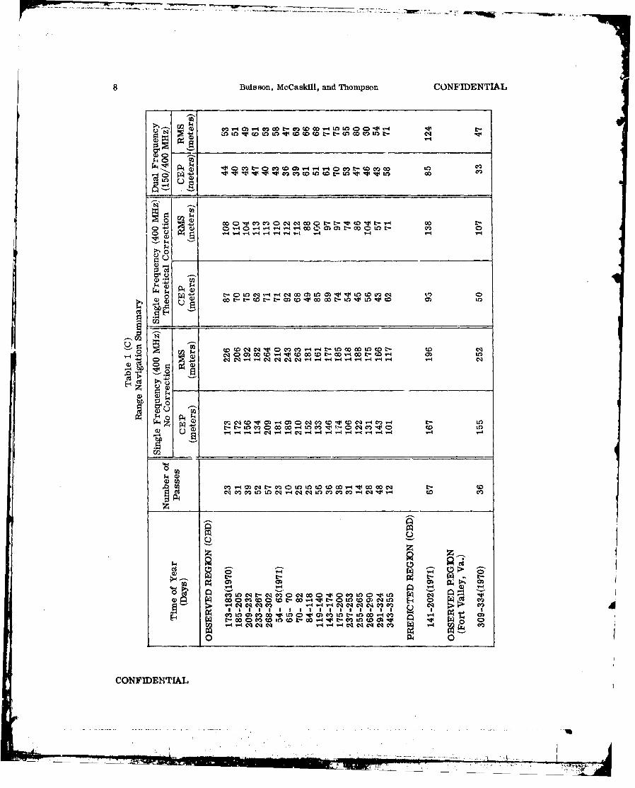
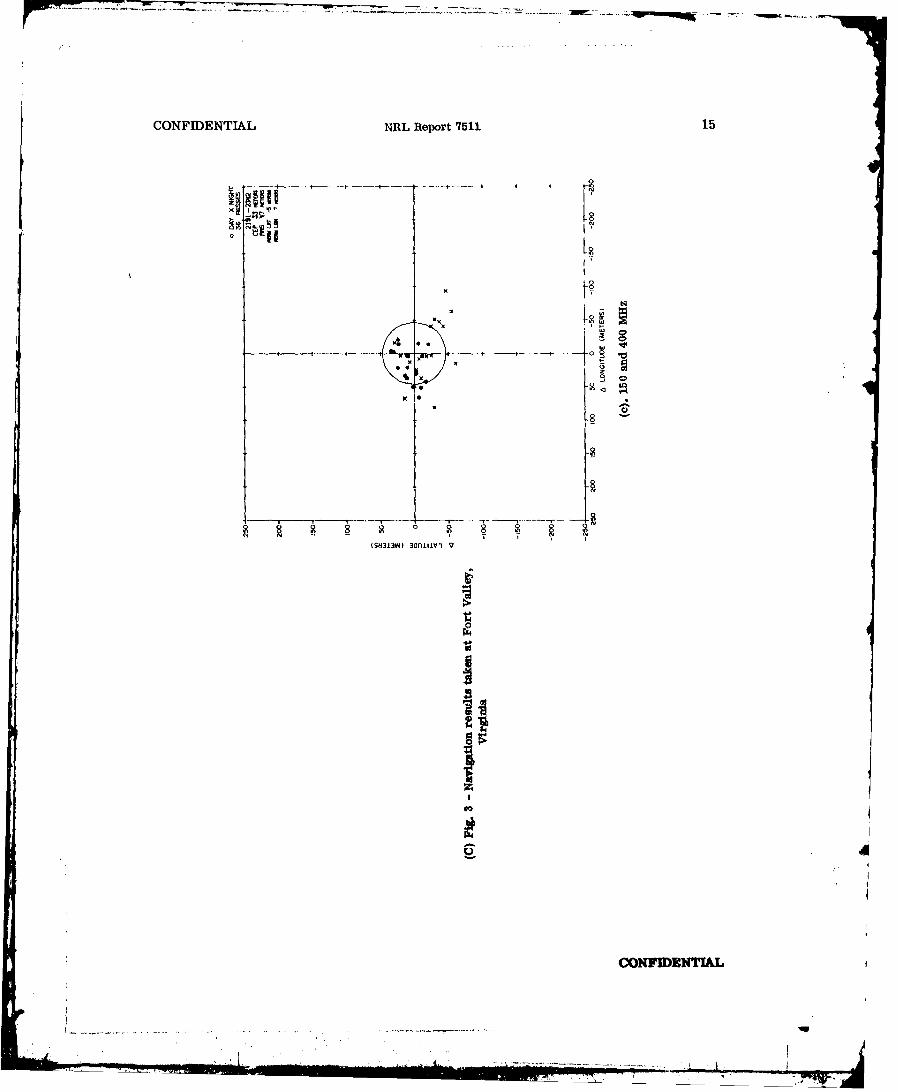
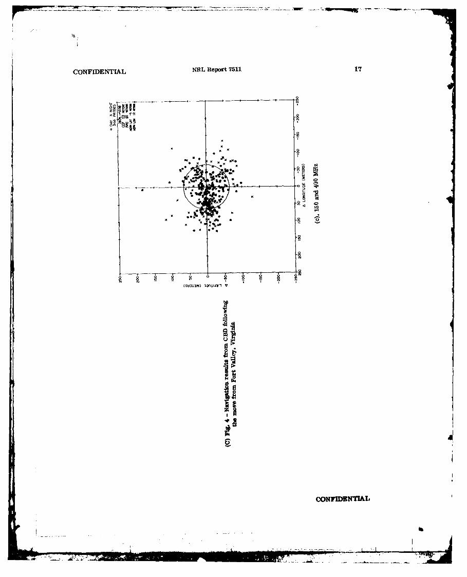
(U) A summary of navigation results is given in Tables 1 through 4. Included are re-sults from the four field stations previously mentioned. One location, included in Table 1,but not mentioned earlier, is Fort Valley, Virginia. The CBD station was moved to thissite for approximately one month near the end of 1970. This move is of significance as areference point in discussing the CBD navigation results. In Figs. 2 through 4, three timespans are covered. They are (a) before moving to Fort Valley, (b) the time at Fort Valley,and (c) the time after leaving Fort Valley. These three groups of graphs include all theobserved data covered in Table 1. An analysis of these navigation solutions shows thatthe best results were obtained while at For, Zalley. This outcome is possibly due to thelack of electronic interference at the Virginia site. On examining just the CBD data, thetime prior to the move to Fort Valley produces better navigations than the period afterreturning to CBD. One possible reason for this is a change of the 150-MHz receiver; anew one was installed at CBD after the station was reopened. Another possibility is theincreased interference observed from newly activated transmitters located near the CBDsite.
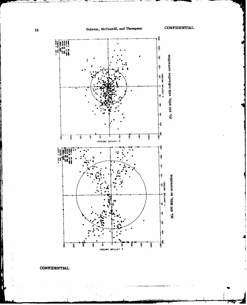
(U) Each of these three time spans is represented by three graphs (Figs. 2 through 4).Consistently, navigation fixes using the dual-frequency method are an improvement overthe navigation solutions using only the theoretical models, and both of these results arebetter than the results using no ionospheric correction. To further illustrate the im-portance of the need for a correction for ionospheric refraction, consider the first graphof each set (400-MHz range, no correction). On these graphs, approximately 75 percentof the passes within a circle scribed with a radius \"NAV) equal to 150 meters are nightpasses. This fact illustrates that the effects of the ionosphere are less at night thanduring the day, resulting in more accurate nighttime navigations. Use of the Chapmanmodel brings the day passes toward the origin to a greater degree than the night passes.The results show that in the second graph (400-MHz range, navigation with refractioncorrection) of each set, no distinction exists between the TNAV's of the day and the TNAV'sof the night passes. When the dual-frequency method is used, all the passes are broughtcloser to the crigin. The results again show no discernible difference between night andday passes.
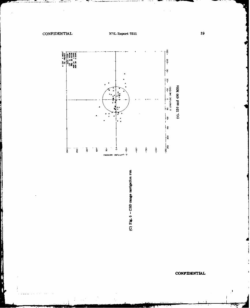
(U) In Tables 1 through 4, the navigation runs are in groups of 75 passes or less. Thereare two reasons for this. First, the navigation program was written so that it cannot solvemore than 75 passes at a time. Second, the magnetic tapes that store the trajectory in-formation contain approximately 200 passes, and only one tape can be used per computerrun. Not all of these 200 passes are taken at each station, and of the ones taken not allcan be used in the navigation runs. From the 200, perhaps less than 75 can be used; of ifmore than 75, the data must be divided into two runs. Examples of typical navigation runsover the time covered by this report are given in Figs. 5 through 8.
CONFIDENTIAL
6 Bulsson, McCaskill, and Thompson CONFIDENTIAL
(U) The criteria used in selecting acceptable passes were mentioned previously in thisreport. First mentioned were requirements for maximum and minimum elevation angles.CBD will be used as an exlample here (Table 5). Any of the~ other stations would showsimilar results. The data again are separated relative to the move to Fort Valley,Virginia.. The data are separated according to maximum elevation angle within eachtime span for the three corrections used. The first separation is by thirds; under 30 de-grees, and over 30 degrees and under 60 degrees, and over 60 degrees. These divisionsdo not alter the navigation results. The answers are independent, within the limits or-iginally set, of maximum elevation angle.
(U) From November 1970 through July 1971, navigation solutions were made using a pre-dicted orbit, in addition to the observed orbit from which the previous results were ob-tained. The orbit is determined by data from the 15 TRANET tracking stations. For theobserved region, orbit fits of ten meters or less are realized. The uncertainty in theposition of the satellite increases as a function of the length of time into the predictedorbit region. This uncertainty shows up in poorer navigation solutions.
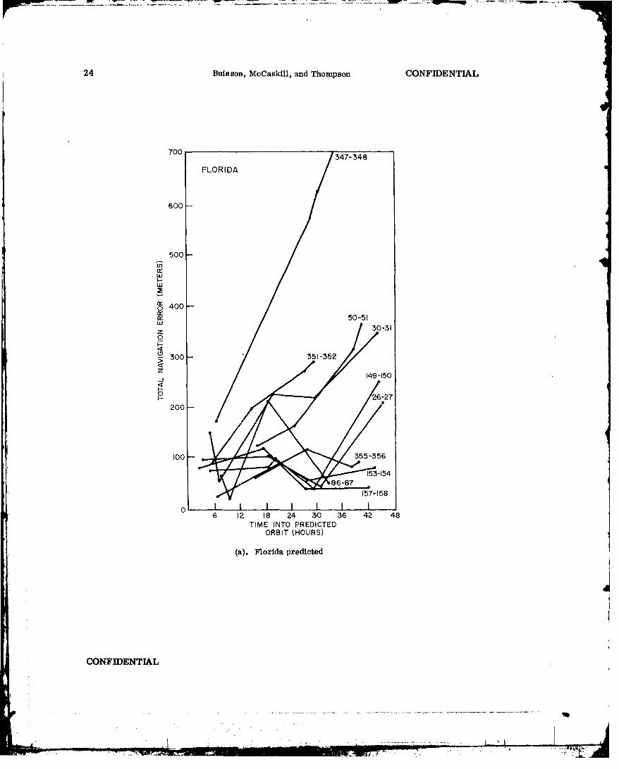
(U) The satellite trajectory data sent from NWL consists of two days of observed data,followed by seven days of predicted data. During this nine-month period the trajectorywas sent every fourth day; in the navigation runs a cycle of two days of observed data,then two days of predicted data were used. When computing an orbit , the fit of ten metersno longer holds in the predicted region. A graph depicting the increasingly poorer answersis presented in Figs. 9a and 9b. These examples show how TNAV increases as a functionof time into the predicted region. The stations used in this example are NRL and Florida.The days in these graphs were chosen because for each two-day period, at least four passeswere taken at both of the stations. The same days are used to illustrate the similarity inoverall slope for each two-day run. For each station the four passes used are not nec-essarily the same, which indicated that the trajectory for thl,3 predicted period is thereason for the resulting increased navigation errors.
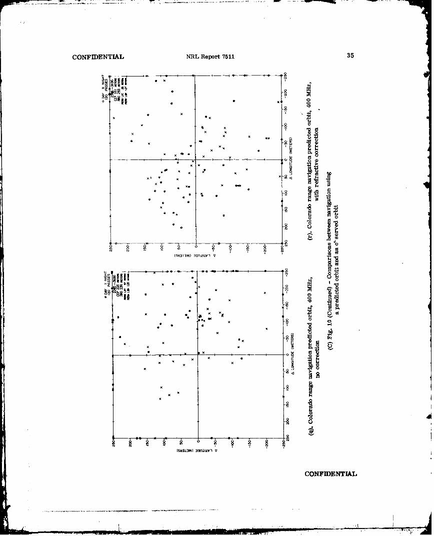
(U) Figure 10 is used to cumpare the navigation error resulting from the use of orbitaldata in the observed and predicted regions. In making the comparison of observed versuspredicted data, it is useful to know the orientation of the satellite velocity vector at thetime the satellite is at maximum elevation with respect to the ground station. The TIMA-TION II satellite has an inclination of 70 degrees, and the ground stations are located at
I mid-latitudes (30 to 40 degrees). These parameters result in a north-to-south orientation,with a small east component, of the velocity vector of the satellite at the maximum eleva-tion point. The positional error due to the use of predicted satellite trajectory has itslargest error component along the track of the satellite orbit, which results In a navigationerror that displaces the station along the direction of the velocity vector and appears pri-inanly as a latitude error of the station. A cross-track error appears primarily as alongitude error. The observed data span shows cross-track, longitude errors. In the pre-dicted region, the predominant )rror is along-track, or latitude, errors. These errorsare summarized in Table 6. For all the stations and all the corrections, the CE P's ofthe longitudes and latitudes are given for both the observed and predicted regions. TheaeCE P's were calculated by taking the magnitude of the error in latitude or longitude for allthe passes and computing an average. When these results, for the observed and the pre-dicted time spans, are compared, the latitude CEP consistently shox-,s the greater change.Figure 11 combines the CE P's of latitude and longitude to give graphic representations ofthese changes. When comparing the predicted to the observed runs, the similarities areevident at all the stations for the corrections used.
CONFIDENTIAL
CONFIDENTIAL NRL Report 7511 7
CONCLUSIONS
(C) Of the three navigation solutions calculated, the solution using the dual-frequencyionospheric correction provide the best navigations, with an average CEP position-fixingcapability of 48 meters. The single-frequency method, using a theoretical ionosphericmodel, is next best, with an average CEP position-fixing capability of 68 meters. Theleast acceptable results use the simple single-frequency solution, with an average CEPposition-fixing capability of 156 meters. The best navigation results were from the dual-frequency solution at Fort Valley, Virginia, with a CEP position-fixing capability of 33meters. The navigation errors caused by use of a predicted orbit are a result of theuncertainty in the position of the satellite, especially along the track of the orbit. Thisbias results in more latitude than longitude error. The accuracy of the navigation solu-tions is independent of their maximum elevation angles.
ACKNOWLEDGMENTS
The authors acknowledge the guidance and encouragement of Mr. R. L. Easton, Headof the Space Metrology Branch and Mr. D. W. Lynch, Head of the Advanced Techniquesand Systems Analysis Section. The authors are indebted to Mrs. Cecelia Burke for hercontribution in the data compilation for this project. The authors further acknowledge themembers of the Space Metrology Branch who designed and constructed the TIMATION IIsatellite and range receivers. The authors also acknowledge the Bendix Field Engineeringpersonnel who operated and maintained the TIMATION field stations and the Space M., rologyBranch personnel who operated and maintained the NRL ground station.
Special thanks are extended to Mr. R. J. Anderle, Mr. Robert Hill, and Mr. LawrenceBeuglass of the Naval Weapons Laboratory for their assistance in the calculations of theTIMATION orbit trajectories.
REFERENCES
1. NRL Space Metrology Branch, "The TIMATION I Satellite" (Confidential Report,Unclassified Title), NRL Report 6781, Nov. 18, 1968
2. Easton, R. L. and Bartholomew, C. A., "The ThermalDesign of the TIMATION I Satellite,"NRL Report 6782, Jan. 1969
3. "Documentation of ASTRO Mathematical Processes," NWL Tech. Report TR-2159
4. McCaskill, T. B., Buisson, J. A., and Lynch, D. W., "Principles and Techniques ofSatellite Navigation Using the TIMATION II Satellite," NRL Report 7252, June 17, 1971
5. Lamont V. Blake, "Ray Height Computation for a Continuous Nonlinear AtmosphericRefractive-Index Profile," Radio Science, Vol. 3, No. 1, 85-92, Jan. 1968
CONFIDENTIAL
Aw
27777718Buisson. McCaskill, and Thompson CONFIDENTIAL
v0 MMVC.ML) OW Ot -U)O >U t- C4"
t4A
fr0 0
0 ~cl)
UU
E.O
U 4' M M r4t-SWw o WL o0
cq C M MW V4 V M o t-W " t-W " (0
o ______C-4_______._._._._-4___4_?-I_-4__-____4_
0 0,
CONFIDENT1cIAL) MQ q oto t c IqM q t-L
u v -v-Mc l000 - 4 f-0c 0tr-4~ ~ ~ -4 -4 1- -N 4- qV414V- Ir ý1 4-

CONFIDENTIAL NRL Report 75119
c) > 4, m wt )"L t 4ý c >m(
o d + U)0 0 N ") ~ - 4 1.4 -m C) -V) 4 v - r-" r-4 rq-I ,4 r4 -4 ,- C 14 V-4
04
E--.
cd~
'4-a
c -15
CONIDETIA
..................................... k

10 Buisson, McCaskill, and Thompson CONFIDENTIAL
CD0 400C)O q -Qt Mwt tItC' ~ L C>
0) V-4 V- CQ %Vi4C ']-
0
N
Cdcy-
Co w M_"_Mt-___M_____ 0_LO__ w_=_C__V) ____wt-_
w 1-40MMI100 0co-4
~OOVcq 4 ItL-4 O
__ _ _ _ __ _ _ _ _ __ _ _ _ _ __ _ _ _ _ 4- .
CONFIDENTIAL v -c --q10V-

CONF'IENTIAL NRL Report 7511 1
r-o 4'M 0 CV4 -j
rx4P, 0 fD C'ý0 0
C- 00 0 o"a -4 V-4 -4
'-4
$4
W.
Om w 0 -1 O LenwMNW U q
w V. .J N Nt
up o -4 M -(. . . . -4r- m m 9
o 0
$40.
r-4 1- ~4 V-4L~qt
0i' V 0(V- - N MM V- -
W Q M W " M t W C0-4!2 0O w U
__ _ 0
CONFiDENTIAL

12 Buisson, McCaskill, and Thompson CONFIDENTIAL
00
00x 8
x 0 x0Q
0
x K
8
K K K-all. 0
KK
MKK
(S xVd 3lIJVx
CONFIENTIA

CONFIDENTIAL NRL Report 7511 13
Itiit
xiixw x U
(SU3119I) 30rJllIV1 V
4)
0
CONF13DZNTIAL
S............ ' . ....
.. .

14 Buisson, MoClaMkl, agxd Thomnpson CONPIDENTIAL
F I~
00
(sviu) wnuvi0
CON 2 0A
~3I~? Qfl1~±1 V 7
CONFEDENTIAL NRL Report 7511. 15
x I . 4.
Ix
4..
(s~ino 3anari
[ CONFDN
16 Buisson, McCaskill, and Thompoon CONFIDENTIAL
x IS5
0M 2
x 0x X0
( :i34i 30AkI .* I
0 0 2(S1LE x QlI*
CONFIENTIA
x 0.
CONFIDENTIAL NRL Report 7511 17
xg --
g
K if K
X ode
~ 2 0 ~ 8 2 2
CONFIDENTIAL

18 Buisson, MoCaskill, and Thompson CONflDENTLAL
x x
i smno 3onuv-
- C
Pk)
30.11
CONFIENTIA
0 i.
CONFIDENTIAL N'L Report '7511 19
x x
x X
x
CON*DIMM

20 BulB mm UcCaskill, arnd Thbmpsmf CONFIDENTIAL
KK x
00
4'P4
0
x0
I* x
(Si1W alIx~
COI4ITPETJA

21
CONFIDENTIAL NRL Report 7511
0xQ
8.x
x~x X
x x If a X
x x
x0,x :
x8
C N N
'0
IP xI
x$33)~n~X
CONF1DxTI 8

-7w- --
22 Buisson, McCaskill, and Thompson CONFIDENTIAL
0 0
T
.46* 8
X" x
'K,
x x x
x x 0
42 OD 0 22'~ - ' T
X xx
'B x
K aS CD
_ _ _ _ _ _ _ _ _ _ _ KKilV 0
CONFIENTIA
"ar*

CONFIDENTIAL NRL Report 7511 23
SC> ,,co-. 0 t..- 0o m m , ,o - to ,..*41 t-u - 0m.. C-t C- w.1 w,-.4
o o
a)
[,.) .44 W, ,-4 C,,1
0• ,.) i ýo C1 oo " m oC oC4M wC
ri-4 -i c V-1 ~ -1 -4 C-4 -4 lv4 C4 4
C14
o to ,,- m u .. - " -4 ,-mc . "4
'U M' 1- '"'D0 Oat m t -0m
81 t
r/l -. 4 E
4-i 0
149V v0 oo m 0 0QV O c
C ;4
O oz0
.C.4~ 0 0 0,0
P.j 00 0. LOO- 0 ~ 0 ~ 0 0 a
0 C 00 to 0L C) (00 '4LO 0 C 0 0 4LO o
F4~ moo V O ci04 VL o 0t&4 45 k ~ m4 to k14 01o .D k "4&4 V) k
'ýWG 0 ~ 00O LD 0z 10W P
CONFIDENTIAL
24 Buisson, McCaskill, and Thompson CONFIDENTIAL
700 347-348
FLORIDA
600
500
I--ILi
0 400
c" 50-51hi
z 30-31I-5
300 351-352
z149-150
200
100 5-6
157-158
,0 , 1, 1 1 I ! . ,.16 12 18 24 30 36 42 48
TIME INTO PREDICTEDORBIT (HOURS)
(a). Florida predicted
CONFIDENTIAL
--------------------------- ~J

CONFIDENTIAL NRL Report 7511 25
7003434
NRL
600-
500
w 50-51
~t4000
o 351-352
LD 300 - 30-31
200
100 1
6 12 16 24 30 36 42 48TIME INTO PREDICTED
ORBIT (HOURS)
(b). NRL Predicted
(C) Fig. 9 - Relationship between total navigation errorand time Into predicted region
CONFIENTIAL
-- -------- -- --------

26 Buisson, McCaskill, and Thompson CONFIDENTIAL
S'It ,-i
0%0 0
i 0
K 14
IV 0 !
CONFIDENIDA
00
px
K 0
0
K K K.
S...... , ... .~ ~~ K " K • i 'i . . , • , _ , . . . .

CONFIDENTIAL NRL Report 7511 27
C -8
S.. .. - K . . . . . . . ... .
10ON6..F T
u
T T
CONFIDENTIAL

28 Buisson, McCaskill, and Thomp son CNIEqJ~
14.
N ~-44NOT
NM J

CONFIDENTIAL NRL Report 7511 29
e x
sex
'0
CONFIDENTIAL
* C
TM . , TM- , . . . . . .. . . .-•" '• ... .. ' -- • -- mT n -, • •I I I I I ' . . . ' • * ' ".. '* ' -

30 Buisson, !AcCaskffl, and Thomipson CONFIDENTIAL
4-r
KM x
x x Ix
w x
4- 4- - 4P 0 0
00
K. "
MS X
x Ix
OXX

CONFIDENTIAL NRL Report 7511. 31
K 2
K K 0K
K. K
K 0 U Kx
K *K 0* K
K K K 4
Ks~w KKj~v V
N1 K
Kx
K 0 * a
muvw~~ Doa
- O IENU

32 Buisson, MeCasidlll and Thompson CONFIDENTIAL
N N,
we ~ ~ ~ I '?ii
(S3Xq 0 1 1 a1
ON -
-
x .6
KK
00 K
v K K8
K .X NO K
Ksua aanKuK K
K -O
K K
NK K
x 0K
K
U x K
K, X
x N, x
re x
CONFIDENTUMJ
.......................................L
OMN

CONFIDENTIAL NRL ReP~rt 7511 33
V x
4b x0 x x x K
x x
.9 * KK U9
0 4
oK K
0 TK- x s
x x
04
0 K
K KX
x
KK 0 1 0
a i1iK KETM
K KK

34 Buisson, McCaskill, and T'hompson CONFIDENTIAL
0.0
K x *
XX x 1
x 6*
4, 0x % 40
0%0
Ix x
8 0 0
(SK1±3V) 3afliLw1 v
CONFIENTIA
CONFIDENTIAL NRL Report 7511 35
* _ -' I- - ---- - -. *
00
K 8
ex 0
K K
K K 0 1
K K KK K
K KS K
x X
x 49 x
0 0 .0
0
ox N
a 8N _ _ I _
(S3tx)~O~v
U-X -
0
K K rTKS M )3nl~
CONFIENT &
K KM

36 Bulsson, McCaskill, and Thompson CONFIDENTIAL
K g 1w m "oo o., 0 t C
,b• 4, qCo ,C,1 t.. m ~ to IVm
1-4, ' -t•,, v,4 ,
0) Co 4m t- 00 -4 4
o ("
m m 0 00
~~C14 C11
Z
'*4u L-qoe )
0)I 0 t t 1 t
V-'-4V-'
• m-
;5 $4 "A0C 0 -. 0 ý4 00I -W -- 4
4to ;4C.)
09
00 0 00 0
W4 N O) WU) 0
•'• • .. ..- •= ::• • , -'• ' • ' I '• • . ..... ..."" 4 , •- I ,- .. - . . _••.- • , ! _ _
00
w C)
CONFIENT&A
-,r~ .wm~.Wl~. , rfl",~W.- "r-r' 'v----
- - - - - - - - --)-- - -
CONFIDENTIAL NRL Report 7511 37
200
' D o -- N RL
(a). Observed data, all stations, single
frequency with no ionosphere correction
-100 --
• 150 --
-20 0 1 . I I I I ] -
1110 100 50 0 -50 -100 -150
LONGITUDE (METERS)
200
(b). predicted data, all stations, singlefrequency withno ionosphere correction - •,
-150 -
0 50 00 0 0 -50 -tOO -150
LORIOITUDE (METERS)
(C) Fig. 11 - Combined latitude and longitude CEP's for observedand predicted data, all stations, and all cosrections
C F0I-150
-200--11, 100 ., 0 0.- -50 -to -15,0 ..
-•, __ .... ,," , .. , ' •.... •-• - •m ,• - , ' ."•" I..,• - -' .'.'" " ,-, •• : ,LON . .... • (METER.S)..

38 Buisson, McCaskill, and Thompson CONFIDENTIAL
200
150
COL
50 BD
(c). Observed data, all stations, single FLA
frequency with theoretical modelcorrection
-50
-too-I
-2o00 .1.
150 1oo 50 0 -50 -100 -150
LONGItUDE (METERS)
150- COL
100--
50 -(d). Predicted data, all stations, singlefrequency with t h e o r e t i c a 1 model
____-__ .._ correction50
-150 -
150 '00 50 0 -50 -Io0 -150 •
LON•ITUDE (METERS)
CONFIDENTIAL
. - ,- - . , , - , . . .. ... .. .
CONFIDENTIAL NRL Report 7511 39
15o PRED50-(e). Florida predicted and observed singlefrequency with no ionosphere correction
,Q ,, 5) 0 -50 -100 -110LOIIGITUDE IME tE•S)
" l ........ . . . .... ...... .-....---... ....-..
(f). Florida predicted and observed singlefrequency with theoretical model correction
"-10 CO 50 0 -50 -. 00 -t-3SONGTUOE (METERS)
(C) Fig. 11. (Continued) - Combined latitude and longitude CEP's for observedand predicted data, all stations, and all corrections
CONFIDENTIAL
. ., A

40 Buisson, McCaskill, and Thompson CONFIDENTIAL
200
'50 PRED
5O0
(g). NIRL predicted and observed singlefrequency with no ionosphere correction 0
-50-
-150 --
0 150 00 '30 0 -50 -100 -1SOL00dTLU0E (METEPS)
PRED
OHS
0 (h). NRL predicted and observed singlefrequency with theoretical model
- ------------*--- --- correction
-50 -
-IOHS
200 150 O 00 0 0 -'50 -100 -150LONWItUDoE OMETERS)
'I
CONF]D1YNTIAL
S~.~------- ---...'-.~~'.~ -*-- ... .-

CONFIDENTIAL NiRL Rleport 7511 41
----- 7
(1). Colorado predicted and observed single-frequency with no Ionosphere c(,rrection
-100
l0oo
"U C-
frequency ITU wit terticlcorcto
-100
ISOS
(C)lrd pig. di(ctined) an Combinved snlattde n ogtd EPsfrosre
and predicted data, all stations, and all corrections
CONFIDENTIAL
42 Buisaon0 McCaskfil. and Tbonpeon CONFIDENTIAL
20050-
500
(k). CBD predicted and observed single 0 -
frequency with no ionosphere correction I
'50 ax) 5o (I . I(XI
I ( M•NW IU[ IM t l451
200
.50
PRED
50 -71B5
____ (1). CBD predicted and observed singlefrequency with theoretical correction
-50 -.
-(00
I50 100 .50 0 -50 -100 -I10LO'INfOE (METERS)
CONFIDENTIAL
.. , - - - - - -- - ---------------.--, ---,--- -..
CONFIDENTIAL NRL Report 7511 43(Page 44 Blank)
Dill U
',t4
-'•,ItD • I V .•%
"lit 00 10
(m). CBD predicted and observed dualfrequency correction
(C) Fig. 11 - Combined latitude and longitude CEP's for observedand predicted data, all stations, and all corrections
C E4
111

CO NFSIENTIALSecuritv Classiticatio ,,
DOCUMENT CONTROL DATA- R & D(Security clto-oica.tion of title, body .1f abstrac't and incrlexri• mnnotntion niu. be er/nterd ,hen the overall report Is Classftied)
I OWIGINA TING ACTIVITY (Corporate CfI.hor) 2*. REPORT SECURITY C LASI'FICATION
Naval Research Laboratory ConfidentialWashington, D.C. 20375 ýh.OLPGDS_71
3 R-PORT TI"TLE
RANGE NAVIGATION USING THE TIMATION U SATELLITE (U)
4 DESCRIPTrIVE NOTFA (Type of report and ihelusive dates)
Interim report on the NRL Problem.nI AU TI-ORISI (First ~name, middle inoitil, last name)
J.A. Buisson, T.B. McCaskill, and J. E. Thompson
0IlPORT DATI: 7e, TOTAL NO. OF PAGES r7, NO. OF REP.-%
'February 12, 1973 48 580. CONTRAACT OR GRANT NO. 9a. ORIGINATOS'S RrPORT NUMMER(S)
NRL Problem R04-16N OROJECT NO NRL Report 7511
A3705382 652B1F48232751C. Sb. OTHER REPORT NO(S) (Any other numb.r thet may be asslined
this report)
d.
to. DISTRIBUTION STATEMKNT
Distribution limited to U.S. Government Agencies only; test and evaluation; February 1973Other requests for this document must be referred to the Director, Naval Research Laboratory,Washin n, D.C. 20375It. SUPPLEMENTARY 14OTF.S I1. SPONSORING MILITARY ACTIVITY
Department of the NavyNaval Material Command
_ PM-1613. A1STRACT (Confidential)
The TIMATION(Time Navigation) technique of passive ranging can be employed to provide aworldwide navigation and time-transfer service. Passive ranging is accomplished bymeasuring the time difference between electronic clocks located within the satellite and thenavigator's receiver. Navigation results were obtained with a prototype system consisting ofthe TIMATION U. satellite and four ground stations. The results indicate a CEP position-fixingcapability of 33 meters (100 feet) using dual-frequency range measurements. The analysis ofthe data includes ionospheric refraction, instrumentation error, and the effect of satellitetrajectory position error in both the observed and predicted regions.
FOR (PAG Ia3,DD4FR 1 4 7 3 (A CONFIDENTIAL
S/N 0101.e007.e801 Security Clawaificatton

CONFIDENTIALSecurity Classification
14 LINK A LINK 8 LINK CKEY? WOROS -"- ' - -
ROLE WT ROLE WT ROLF WT
TIMATIONSatellite navigationPassive rangingClock correctionIonospheric refractionDual frequencyObserved orbitPredicted orbitQuartz crystal oscillatorElevation angle
DD I ,FORM.. 1 4 7 3 (BACK) 46 CONFENTIAL(PAGE 2) Security Clasifilcation
SEEN
7
I CONFPENTIAL NRL Report 7511
Range Navigation Using the TIMATION II Satellite[Unclassified Title]
J. A. BUISSON, T. B. MCCASK[LL AND J. E. THOMPSON
Space Metrology BranchSpace Systems Division
DECLASSIFIEDt By authority of
Cite Authority Date
Entered by .IM Code
February 12, 1973 , .~0 0
- O4.. 4 -• I- " .- ,. • ,
"-"- -- LEJ,'J,
co
Washington D.R
C NN I L...- ""4..
x, 00z
zC:)
NAVAL RESEARCH LABORATORYWashington, D.C.
CONFIN.NTIAL
DISTRIBuIoy LUaLInr?