authentic engineering experience: electromagnetic...
TRANSCRIPT
Authentic Engineering Experience:
Electromagnetic-Induction Keychain Product for a Real Customer
P.R. Stupak, S. Rumrill, B. S. Carlsen, T. George, and J. Suriano
Department of Science and Engineering
Raritan Valley Community College, Branchburg, NJ
The Raritan Valley Community College (RVCC) Engineering program launched a pilot hands-on "Authentic Engineering
Experience" course in Fall 2015 for a Team of four second-year RVCC Engineering students to design,
prototype, manufacture, and deliver a real product to a real customer. The objective of the pilot course was to expose
students early in their academic careers and under "authentic engineering" conditions, to vital skills and practices used
daily in industry. A secondary goal was to give students product development and project execution experience to relate
to potential internship and professional employers. This pilot course will be developed into a full course consisting of 4-5
teams of four students (to maintain small-team authenticity) starting in Fall 2016.
Corresponding Author: Peter R. Stupak, [email protected]
Introduction
The Raritan Valley Community College (RVCC)
Engineering program launched a pilot hands-on
"Authentic Engineering Experience" course in Fall
2015 for a Team of four second-year RVCC Engineering
students to design, prototype, manufacture, and deliver a
real product to a real customer. The product was a
customized electromagnetic-induction "shake-light"
requested by the customer to use as a novel gift for the
Customer's visiting customers to demonstrate their
commitment to higher-education and the environment.
The student Team designed and developed the induction
power supply, the energy storage and LED lighting
circuit, and customized 3D-Printed package complete
with customer name. Although guided at arms-length by
industry-experienced staff, the overwhelming emphasis
was for the student Team to reach their own designs,
experience their own failures and successes in earning
their own know-how, resolve their own communications
and scheduling conflicts, and to respond to customer
critical comments of prototype product performance.
The objective of the pilot course was to expose students
early in their academic careers and under "authentic
engineering" conditions, to vital skills and practices used
daily in industry, including in part: customer
communication and support, teamwork and internal
communications, project responsibility, project
management, continuous improvement, and product
customization. A secondary goal was to give students
authentic product development and project execution
experience to relate to potential internship and
professional employers.
The spirit of this project is in line with previous
successful efforts to expose students to “authentic”
engineering experiences and environments through, for
example, Service Learning [1], Learning Factories [2],
Capstone Projects [3], hands-on 1st-Year Engineering
Courses, Learning in Laboratory Settings [4], and
Engineering courses featuring Mechanical Dissection as
a learning tool [5].
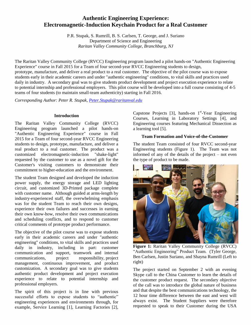
Team Formation and Voice-of-the-Customer
The student Team consisted of four RVCC second-year
Engineering students (Figure 1). The Team was not
informed of any of the details of the project – not even
the type of product to be made.
Figure 1: Raritan Valley Community College (RVCC)
“Authentic Engineering” Product Team. (Tyler George,
Ben Carlsen, Justin Suriano, and Shayna Rumrill (Left to
right)
The project started on September 2 with an evening
Skype call to the China Customer to learn the details of
the customer product request. The secondary objective
of the call was to introduce the global nature of business
and that despite the best communications technology, the
12 hour time difference between the east and west will
always exist. The Student Suppliers were therefore
requested to speak to their Customer during the USA

night for the Customer’s convenience in the China
Customer’s next day morning.
The Customer requested key-chain light embossed with
the Customer’s company logo for use as a novel gift for
the Customer’s visiting customers to demonstrate their
commitment to higher-education and a “greener” planet.
The customer did not indicate or suggest how to achieve
the required product performance – those decisions were
left entirely to the student Team. The Customer product
performance, constraints, price-points, and delivery
requirements are given in Table 1.
Team Brainstorming and Project Planning
Responding to the Customer request, the Team met the
following day to brainstorm ideas, define initial
objectives, create a preliminary project plan, and divide
task responsibilities. The brainstorming used standard
rules where each team-member sequentially gave one
idea and where all ideas were listed without discussion
or critique. The idea was to generate as many specific
and open-ended ideas as possible (Table 2). Based on
the Brainstorming, the Team developed an initial list of
key objectives (Table 3) that addressed the customer
product and timeline as well as key product development
steps and an initial Project Plan where the Task
responsibilities were divided among the team-members
(Figure 2).
Figure 2: RVCC Engineering Team initial project plan
with tasks, sub-tasks, schedule dates, and defined
responsibilities.
Team Research and Division of Responsibility
Although knowledgeable of certain specific
technical concepts that may be used in the project, for
example RC-circuit theory from Physics class, the Team
realized that they needed to learn more to put that
knowledge into action for the project and learn about the
other project technologies. The first tasks from the
project plan divided the technological ideas from the
Brainstorming session into three categories
corresponding to the three main technical challenges for
the product, including: electromagnetic-induction power
supply, the electrical power storage and release, and 3D-
Printing of the product package. Each Team member
assumed responsibility to further investigate specific
parts of these technologies with the objective of reducing
the technology options to a few testable technologies.
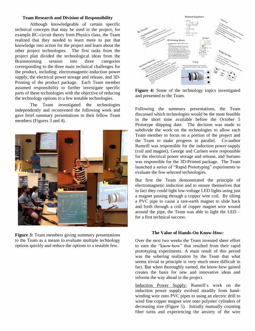
The Team investigated the technologies
independently and reconvened the following week and
gave brief summary presentations to their fellow Team
members (Figures 3 and 4).
Figure 3: Team members giving summary presentations
to the Team as a means to evaluate multiple technology
options quickly and reduce the options to a testable few.
Figure 4: Some of the technology topics investigated
and presented to the Team.
Following the summary presentations, the Team
discussed which technologies would be the most feasible
in the short time available before the October 5
Prototype shipping date. The decision was made to
subdivide the work on the technologies to allow each
Team member to focus on a portion of the project and
the Team to make progress in parallel. Co-author
Rumrill was responsible for the induction power-supply
(coil and magnet), George and Carlsen were responsible
for the electrical power storage and release, and Suriano
was responsible for the 3D-Printed package. The Team
launched a series of “Rapid Prototyping” experiments to
evaluate the few selected technologies.
But first the Team demonstrated the principle of
electromagnetic induction and to ensure themselves that
in fact they could light low-voltage LED lights using just
a magnet passing through a copper wire coil. By tilting
a PVC pipe to cause a rare-earth magnet to slide back
and forth through a coil of copper magnet wire wound
around the pipe, the Team was able to light the LED –
for a first technical success.
The Value of Hands-On Know-How:
Over the next two weeks the Team invested sheer effort
to earn the “know-how” that resulted from their rapid
prototyping experiments. A main result of this period
was the sobering realization by the Team that what
seems trivial in principle is very much more difficult in
fact. But when thoroughly earned, the know-how gained
creates the basis for new and innovative ideas and
informs the way ahead in the project.
Induction Power Supply: Rumrill’s work on the
induction power supply evolved steadily from hand-
winding wire onto PVC pipes to using an electric drill to
wind fine copper magnet wire onto polymer cylinders of
decreasing size (Figure 5). Initially manually counting
fiber turns and experiencing the anxiety of the wire

breaking after 1000+ turns – and not finding the ends –
Rumrill and other Team members worked together to
automate the counting using a photogate that counted the
passes of a stick attached to the drill chuck.
Power Storage and Release: George and Carlsen’s work
was broad initially where they evaluated different circuit
designs including Zener diode triggers, mini super-
capacitors, and multiple capacitors. At first the designs
were complex and intended to solve all the technical
problems together in one solid go. A lot was learned but
experience taught that the complex designs were too
unknown and trouble-shooting not possible (Figure 6).
The decision was made to start from the simplest circuit
possible – a RC circuit containing a resistor and
capacitor leading to an LED light. Start simple and
evolve the complexity only as needed.
3D-Printed Package: Suriano’s work began with the
need to learn the operation and use of both the 3D-
Printer to print the package and the 3D “Inventor”
software to design the package. A variety of object
shapes, sizes, colors, materials, processing parameters,
and finishing methods were tested. Again steady know-
how was gained through dedicated effort (Figure 7).
Figure 5: Know-how gained in winding the induction
power coil included the use of a hand drill to automate
winding, automated turn counting, and the use of fine 42
gauge copper magnet wire.
Figure 6: Know-how gained in designing and testing a
variety of electrical storage and discharge circuits.
Ultimately the Team’s decision was to begin all
investigations of technology and manufacturing methods
with the simplest approach possible and add complexity
only as needed to improve performance and reduce
manufacturing time.
Figure 7: Know-how gained in learning the 3D-Printer
and 3D design software including a variety of object
shapes, sizes, colors, materials, processing parameters,
and surface finishing methods.
Leadership, Project Management, and Control
The project leadership was rotated weekly among the
Team members. The Team Leader for the week was
responsible to maintain overall project coordination,
communication, and lead the Weekly Team Meeting. At
the start of every Weekly Team Meeting the Team
Leader also was responsible to monitor and maintain
project progress through the use of weekly “Report Out”
sessions. The Report Out was a brief review of the
Project Management Gantt chart where the Team
member responsible for each line-item task due that
week or within the next few weeks gave a status update
for the task with no discussion allowed. In this manner
the entire project was reviewed in less than 10 minutes,
all Team members understood the status and risk areas,
and the Project Plan was updated by the Team Leader
that week. Only after the Report Out was discussion
allowed and Team members needing to discuss key
points could do so without involving all members of the
Team. The Weekly Team Meeting was also an
opportunity for full Team collaboration to integrate their
individual efforts. Many good Team problem-solving
sessions were conducted at the Weekly Team Meetings
(Figure 8). Therefore the Weekly Team Meeting was a
productive opportunity to be informed, communicate,
collaborate, and make progress.

Figure 8: Weekly Team Meetings were an opportunity
for Team Members to “Report Out” and be informed of
the full project progress, communicate, and collaborate.
Prototype and Customer Feedback
Five units of the prototype product were shipped to the
Customer for critical review October 5 – only 33
consecutive days since the start of the project. The
Team’s effort to converge on a design and make the five
prototypes was very significant and their achievement
notable. The prototype consisted of an induction power
supply of 3000 turns of 42 gauge copper magnet wire
wound around a precision-polymer-tube (a drinking
straw) and a ¼” rare-earth magnet, a 1000uF capacitor, a
15k Ohm resistor, a 2.1V clear LED light, and a custom
3D-Printed rectangular package with the Customer’s
company name embossed (Figure 9).
Figure 9: The prototype product was shipped to the
Customer only 33 consecutive days after the start of the
project.
The Customer distributed the prototype units to the
factory Engineers who cut-open all five units to critically
examine their performance and construction. The result
was a list of deficiencies that were presented to the Team
November 2 (Table 4).
During the one month between the prototype shipment
and critical feedback, the Team made progress on
improving the product manufacturing methods and
performance, but naturally at a lesser rate than that
required during the intense period up to the prototype
shipment. However, following the Customer feedback,
the Team needed once again to muster the energy and
focus to address the product shortcomings. This
reinvigoration of any Team following the effort to
achieve a major interim milestone is not easy.
The Team began again by Brainstorming possible
solutions to the Customer issues and focused on four
main technical areas including, increasing the electrical
charging of the capacitor per shake to make the product
light brighter in fewer shakes, maximize the LED
brightness and “on” time, reduce the magnetic field
outside of the package, and improve the 3D Printed
lettering quality to better showcase the Customer’s
company name. After two weeks the Team significantly
improved the product performance by increasing the
number of turns of copper magnet wire from 3000 to
7000 to increase the voltage produced per shake, adding
a bridge rectifier electronic component to capture the
electricity made during both directions of the shake
instead of the previous one direction, and both using a
new tougher and brighter polymer packaging material
and improved embossed letter edge definition for the
Customer’s company name (Figure 10).

Figure 10: The first version of the improved product
following the Customer’s critical performance feedback
for the prototype units (Nov 18, 2015) – now the LED is
bright after only 8 shakes, remains bright for >20s, and
the 3D Printed package is a bright iridescent blue.
Design Freeze
The Customer’s initial request was for the final product
to be shipped by December 5. Given the mid-November
date at this point in the project, the Team needed to
freeze the final design and begin manufacturing the
products to meet the ship date less than three weeks
away. Delays to a design freeze costing several days
resulted from continued testing to maximize the duration
of the LED highest brightness as well as improvements
to the 3D-Printed lettering.
Then an unexpected technical surprise was identified
that precluded hope of a design freeze until it was
resolved. The problem was an off-shoot of the fact that
the magnetic field of the strong magnet used for the
electromagnetic induction power supply extended
outside of the 3D Printer package. This fact was
identified earlier by the Team and again by the
Customer’s Engineers. Although the strength of the
magnetic field was believed to be lower than that
required to damage credit-cards, it was strong enough to
attract Chinese coinage – which is based on a steel alloy.
Therefore the new unexpected surprise was that if the
Customer’s customers used the keychain and carried it in
their pocket, then upon removal from the pocket the key-
chain product would hold coins attached to its surface
resulting in the inconvenience of coins falling on the
ground and sending a negative message about the
Customer!
The Team at first put its hope for a quick resolution by
using a high-permittivity alloy foil to attempt to shield
the magnetic field. But the foil strongly attracted the
induction magnet and prevented the operation of the
product.
In the meantime time was passing and the December 5
final ship date lapsed without a solution and a final
product design freeze.
With the hoped solution now defunct, the Team
employed a process of sequential “3-day tactical plans”
that focused the Team’s work on immediate potential
solutions and thorough but rapid evaluations.
It’s important to note that by this point of the project the
Team was functioning as a thoroughly seasoned and
effective Team. Communication was excellent,
leadership was shared and respected, and the
responsibility of completing the project successfully was
taken fully and seriously by each Team-member.
The Team ultimately decided to strategically enlarge the
diameter of the package such that when the magnet was
positioned at the most likely end position, the package
diameter would be large enough so that the magnetic
field at the surface would just slightly attract the lightest
Chinese coin. This approach to strategically modify the
product 3D Printed package was successful and resulted
in a tapered “Peanut” shaped product that was still
compact and met all other Customer performance
requirements (Figure 11).
Figure 11: The final shape of the 3D-Printed product
package designed such that the strength of the magnetic
field at the end of the product is strong enough to only
slightly attract the lightest Chinese coin.
Teamwork and Final Product Shipment
Throughout the period required to solve the magnetic
field problem, the Team continued to make progress in
innovating and improving the product manufacturing
methods, including the use of spools to contain the
copper wire coil (Figure 12), a pre-printed component
“jig” to unambiguously organize the electronic
components in position and correct polarity prior to
soldering (Figure 13), and the actual 3D-Printing of the
final product package (Figure 14).
Once the magnetic field problem was resolved, the Team
then focused on manufacturing the final products to ship

to the Customer. With the original December 5 ship
date passed and College Final Exams in session, the
Team members continued nonetheless to work making
their individual component subassemblies and meeting
to fully assemble and test each final product. The Team
worked through the Holidays and made the final
shipment to the Customer December 28 (Figure 15).
Figure 12: The final electromagnetic induction power
supply manufacturing method included drill-wound 40-
gauge copper magnet wire (8000 turns), automated
counting, and spools to hold organize the wire.
Figure 13: The final electrical storage and discharge
electronics used a pre-printed jig to ensure correct
component position, polarity, and assembly and included
a bridge rectifier, 1000uF capacitor, 1.5kOhm resistor,
and 2.1V LED.
Figure 14: The final 3D-Printed product package
contained pre-formed supports to hold the induction
power supply polymer tube, electronic component jig
and components, and LED, and was formed in the
“Peanut” shape to reduce the external magnetic field
strength.
Figure 15: The final Raritan Valley Community College
(RVCC) “Authentic Engineering Experience” Induction
Key-Chain Product designed, manufactured, and
delivered to a real Customer December 28, 2015.
Customer Reactions
One of the authors of this paper (i.e., Stupak) was in
China in January 2016 and met with the Customer. The
Customer commented, “The student team did excellent
work and the improvements in the product performance
since the prototype are remarkable! This is an excellent
project. We are pleased to support this type of higher
education.”
A secondary Customer remarked, “This is a fantastic
work and I will give the highest points to these four
students! It is too good to believe that it actually
happened!?”

Conclusions/Implications
The "Authentic Engineering Experience" pilot course
was successful to expose students to vital industry skills
and concepts under simulated but realistic hands-on
industrial Engineering conditions that resulted in a
mature, cohesive, and effective student team that
delighted their customer. This pilot course will be
developed into a full course at RVCC consisting of 4-5
teams of four students (to maintain small-team
authenticity) starting in Fall 2016.
References
1. James L.Huff, Carla B. Zoltowski, and William
C.Oakes, “Preparing Engineers for the
Workplace through Service Learning:
Perceptions of EPICS Alumni,” Journal of
Engineering Education (January 2016): 43 – 69.
2. John S. Lamancusa, Jose L, Zayas, Allen L.
Soyster, Lueny Morell, and Jens Jorgensen ,
“The Learning Factory: Industry-Partnered
Active Learning,” Journal of Engineering
Education (January 2008): 5 - 11.
3. Alan J. Dutson, Robert H. Todd, Spencer P.
Magleby, Carl D. Sorensen, “A Review of
Literature on Teaching Engineering Design
Through Project Oriented Capstone Courses,”
Journal of Engineering Education (January
1997): 17 - 28.
4. Milo Koretsky, Christine Kelly, and Edith
Gummer, “Student Perceptions of Learning in
the Laboratory: Comparison of Industrially
Situated Virtual Laboratories to Capstone
Physical Laboratories,” Journal of Engineering
Education (July 2011): 540 - 573.
5. Heshmat A. Aglan and S. Firasat Ali, “Hands-
On Experiences: An Integral Part of Engineering
Curriculum Reform,” Journal of Engineering
Education (October 1996): 327 – 330..