august 17th, 1929 15 cents simple way to measure the …€¦ · august 17th, 1929 15 cents ......
TRANSCRIPT

AUGUST 17th, 1929 15 CENTS
REG. U.S.PAT. OFF
The First and Only National Radio We e'tt y386th Consecutive Issue-EIGHTH YEAR
SIMPLE WAY TO MEASURETHE MU OF A TUBE
CHARACTERISTICS OF 220,240, 201A, 112 and 171A
AMAZINGLY SENSITIVE4 -TUBE AC CIRCUIT
4TOSEC.
WIRING OF 224-227-245 ABC SUPPLY
TO 724 v. SEC.
/ AMPFUSE
TO CEN, TAP2.S e ACAInk SEC.
Eif/0 VOLTS
-cCCccC3 C4 Cs CI c2;
CHOKES/ 23 4\724
AC-)
.5v. AC
I2.Sr ACAMR
NO TES(A) CONNECT CEN. TAP OF
...re SEC. TO CHOKELEAD NO. 1
699 CONNECT cEN.7-19,0 OF2.6v /2 Airlf? SEC. TO
TO CEN, TAP724 r. SEC.
t
TO CHOKE LEAD 1TO CHOKEP ro CHOKE LEADS* 1'2 $3 LEAD At 4
-2...cv /2 AMR; C+.2 S"+.50 8+180 8+250
'.TO .2. SY /9C: 2.Sv AC'3 AMP SEc /2 Aifie SEC.
TO //O VoZrAC LINE Picture Diagram of an ABC Supply for
224, 227 and 245 Tubes. See page 9.RADIO WORLD, owned and published by Hennessy Radio Publications Corporation, 145 West 45th Street, New York, N. Y. Roland BurkeHennessy, President and Treasurer, 145 West 45th Street, N. V.; Herman Bernard, Secretary, 145 West 45th Street, New York, N. Y.

RADIO WORLD August 17, 1929
Rider Lifts a BIG Load Offthe Service Man'sChest!In New Book Noted Radio Engineer Devotes 240 Pages toTrouble Shooting in All Receivers and Gives the WiringDiagrams of Factory -Made Sets in 200 Illustrations -YouCan Carry This Book Around With You -No More
Torture Tracing Out Circuits.
"Trouble Shooter'sManual" By john F. Rider
JUST OUT!The first comprehensive volume devoted exclusively to the topic
uppermost in every service man's mind is "Trouble Shooter's Manual,"just published. It is not only a treatise for service men, telling themhow to overcome their most serious problems, and fully diagrammingthe solutions, but it is a course in how to become a service man. Itgives all the details of servicing as they have never been given before.Finding the right mode of attack, applying the remedy promptly andobtaining the actual factory -drawn diagrams of receivers always havebeen a load on the service man's chest. But no more. Rider, experton trouble shooting, has produced the outstanding volume on servicing,and has taken the load off the service man's chest!
This book is worth hundreds of dollars to any one who shoots troublein receivers -whether they be factory -made, custom-built or home-madereceivers. The home experimenter, the radio engineer, the custom set -builder, the teacher, the student, -all will find this new book immenselyinformative and absolutely authoritative.
Wiring Diagrams ofBesides 22 ohapters covering thoroughly the field of trouble shooting, this volume
contains the wiring diagrams of models, as obtained direct from the factory, a wealthof hitherto confidential wiring information released for the first time in the interestof producing better results from receivers. Yon will find these diagrams alone well
R. C. A.60. 62, 20. 84, 30,105, 51, 18, 32, 50,25 A.C., 28 A.C., 4LReceptor S.P.U., 17,18. 33.
FEDERALType F series filament,type E series filament.type D series filament,Model B. Model H.
ATWATER-KENT MAJESTIC10B, 12, 20, 30, 85, 70, 70B, 180, power48, 32, 33. 49, 38, 38. pack 7BP3, 7P6, 7P337, 40 42, 52, 50, 44, (old wiring) 8P3,43, 41 power units for 8P6, 7BP13.37, 38, 44, 43, 41.
CROSLEY FRESHMANXJ, Trirdyn 8E3, 601, Masterpiece, equaphase,401, 401A, 608, 704, G, G-60-8 power sup -B and C supply for ply, L and LS, Q15,704, 704.1. 704B, 705, K, K -60-S power706. supply.
ZENITH39, 39A, 392, 392A,40A, 35PX, 35APX,3521X, 352APX, 37A,85P, 35AP, 352P,352AP, 84P, 842P, 33,34 35, 35A. 342, 352,352A, 362, 81. 32, 333,353A, power supplyZE17, power supplyZE12.
Here are the 22 chapter headings:SERVICE PROCEDUREPRACTICAL APPLICATION OF
ANALYSISVACUUM TUBESOPERATING SYSTEMSAERIAL SYSTEMS"A" BATTERY ELIMINATORSTROUBLES IN "A" ELIMINATORSTROUBLE SHOOTING IN "A"
ELIMINATORS"B" BATTERY ELIMINATORSTROUBLES IN
NATORS"13" BATTERY
ELI M I
FADA50/80A receivers. 460AFade 10, 11, 30, 31.10Z, 11Z, 30Z, 31Z,16, 17, 32, 16Z, 32Z,18, special, 192A -192Sand 192BS units,It80A, 480A, and SF60/80A receivers. 460Areceiver and 1160 unit.7 A.C. receiver, 475IJA or CA and SF45-75 UA or CA, 50, 70.71, 72, C electric unitfor special and 7 A.C.receivers, ABC 6 volttube supply, SOY and82W, 5180Z powerplant and E 420 powerPlant.
FREED-EISEMANNNRS, FElv, NR70,470, N R 5 7. 457,NR11, NBSO DC.
JOHN F. RIDERMember, Institute of Radio Engineers
All These Receivers!worth the price of the book. The wiring diagrams are ,a new and old models, of
receivers and accessories, and as to some of the set manufacturers, all the modelsthey ever produced are shown in wiring diagrams! Here is the list of receivers, etc.,diagrams of which are published in this most important and valuable book:
TROUBLE SHOOTING IN "B"BATTERY ELIMINATORS
SPEAKERS AND TYPESAUDIO AMPLIFIERSTROUBLE SHOOTING IN AUDIO
AMPLIFIERSTROUBLES IN DETECTOR SYSTEMSRADIO FREQUENCY AMPLIFIERSTROUBLE SHOOTING IN RF
AMPLIFIERSSERIES FILAMENT RECEIVERSTESTING, AND TESTING I.EVICESTROUBLES IN DC SETSTROUBLES IN AC SETS
RADIO WORLD, 145 West 45th St., New York, N. Y.(Just East of Broadway)
Enclosed please find:0 $3.50 for which please send me postpaid "Trouble Shooter's Manual," by John
F. Rider, being Part II of "Service Man's Manual." 240 pages, 81/2:11",more than 200 Illustrations, including wiring diagrams of commercial receiversas advertised; imitation leather cover, gold lettering.
0 Rider,/or which please send me postpaid "Mathematics of Radio." bY John F.128 pages, 8%x11", 119 illustrations, flexible cover, this being Part
I of "Service Man's Manual."
NAME
ADDRESS
CITY STATE
STEWART-WARNER200, 305, 310, 315,320, 325 500, 520.525, 700, 05, 710,715. 720, 530, 535,
750. 801, 802, 806.
GREBEMUL MU2. synchro-phase 5, synchrophaseA C 6 , synchrophaseAC7, Deluxe 428.
PHILCOPhilco-electric, 82, 86
KOLSTER4 -tube chassis used in6 tube sets, tuningchassis for 7 tube sets.power amplifier. 7 tubePower pack and ampli-fier. 6 tube powerpack and amplifier,rectifier unit K23.
STROMBERG-CARLSON
1A, 2B, 501, 502, 523,524, 635, 636, 403AApower plant, 404 RApower plant.
ALL-AMERICAN6 tube electric, 8 tube80, 83, 84, 85. 86, 88,6 tube 60, 61, 62, 65,66. 6 and 3 tube A.C.power pack.
DAY FANOEM7, 4 tube, 5-5tube 1925 model, DayFan 8 A.C., powersupply for 6 tubeA.C., B power supply5524 and 5525, motorgenerator and filter, 6tube motor generatorset, 8 tube 110 voltD.C. set, 6 tube 32volt D.C. set.
COLONIAL26, 31 A.C., 31 D.C.
WORKRITE8 tape chassis, 6 tubechassis.
AMRAD70, 7100, 7191 powerunit.
SPARTONA.C. 86.
MISCELLANEOUSDeForest F5, D10,D17, Super ZenithMagnavox dial, Thor-myodyne, Grimes 4DLInverse duplex, Garodneutrodyne, Gored EA,Ware 7 tube, Waretype T. Federal 102special, Federal 59.Kennedy 220, Operadloportable, Sleeper BX1,Armad inductrol.
Some of the Questions Settled in Book:Securing information from the receiver owner, list of questions, practical chartsystem of repairs, circuits and operating conditions.Repairs in the home, method of operation, spare tubes, the process of elimina-tion, recognizing symptoms, examples of practical application, tracing distortion,tracing electrical disturbances; vacuum tube tests neutralizing systems, filamentcircuits, grid circuits, methods of securing grid bias, plate circuits; long aerials.
short aerials, seldctivity, imperfect contact, directional qualities, grounds; "A"battery eliminator types, design, operating limitations, requirements for perfectoperation, AC eliminators, DC eliminators; "A" elminator hum, reasons, voltage,reasons, noise; full wave, half wave, B battery eliminators, filament rectifiers,gaseous rectifier, dry disc rectifier, wiring, parts used, design, voltage regulation.operating limitations, requirements for perfect operation, combination filament andPlate voltage eliminators, AC and DC types; B battery eliminator output currentand voltage, excessive hum, dead eliminator, Door design, reasons for defects,motorboating, punctured condensers, shorted chokes, voltage regulator tubes, functionof filter system, C bias voltages, voltage divider systems, filter condensers, by-passcondensers, voltages in the system; determining voltages in B eliminators, AC, DC,voltage drop, effect of shorted filter system, defective rectifiers, defective transformer,defective chokes, defective by-pass condenser, design of filter system, defective volt-age divider network, relation between hum and output voltage, isolation of troubles,external filters, noise filters; cone, dynamic, exponential speakers, troubles, dead,weak output, distorted output, rattle, continuity testing, windings, magnets, fre-quency filters, testing, chokes, condensers, hum elimination;1 audio amplifier types,transformer, resistance, impedance, auto -transformer, combinations, requirements forperfect operation, operating limitations, tubes, forms of coupling, plate voltage, gridvoltage, filament voltage, isolating condensers, voltage reducing resistances, noises,analysis of trouble, plate current, grid current.
"The Mathematics of Radio"John F. Rider wrote two companion books grouped under the title "ServiceMan's Manual." The first was "Mathematics of Radio," the second "TroubleShooter's Manual." The value of one of these books is more than doubled by the
possession of the other."The Mathematics of Radio," 128 pages, Phial", 119 illustrations, bridges the
gap between the novice and the college professor. It gives a theoretical backgroundso necessary for a proper understanding of radio and audio circuits and theirservicing.
See advertisement of "The Mathematics of Radio" on page 20.

...i!lii.,111l41111111111111111111111111111111111111111111111111111111101111111111111111111111111111111
kup r 'I IIIII /44Zerj
/04.1
110'.111,111111 11 qi '1111111111111Y11111'11111111111111111M1,11:111111i111111111l11 '' Lid
Vol. XV; No. 22 Whole No. 386August 17th; 1929
15c per Copy, $6.00 per Year[Entered as second-class matter, March,1922, at the Post Office at 1\Tew York,N. V., under Act of March, 1879.]
Technical Accuracy Second to NoneLatest Circuits and News
EIGHTH YEARA Week y Paper published by HennessyRadio Publications Corporation, fromPublication Offide 145 West 45th Street,
NewYork, N. Y.(Just East ofBroadway)
Telephone, BRYant 0558 and 0559
SIMPLE Mu METERGrid and Plate Voltage Changes Are Key
By Lyon Brook BattleTHE only methods usually published for measuring theamplification constants of tubes involve the use of somekind of bridge, most of which, are quite complex and madeup of expensive parts. Such arrangements are not at all neces-sary except when the amplification factor is desired to a highdegree of accuracy. A simple arrangement such as that shownin Fig. 1 herewith can be used for obtaining the constant quickly,with fair accuracy and with comparatively simple and inexpen-sive apparatus.
The principle of the circuit is to find what change in the gridbias is necessary to counteract a given change in the plate volt-age so as to keep the plate current unchanged. The grid volt-age is measured with the voltmeter V, which may be of a typewhich is available in every radio experimenter's work shop. Ameter used for measuring the voltage of a storage battery isentirely suitable.The indicating meter A is a milliammeter which has a rangewhich will cover the plate current which will occur for the tube,plate voltage, and grid bias in question. A 0-10 meter is suitablefor most tubes, while for some tubes it would be better to useone having a range of 0-50 milliamperes.The grid bias battery is divided into two parts, one of about3 volts across which a suitable voltage divided P is connected,and a second part outside the voltage divider. The voltage ofthe second part depends on the amount of change in the platevoltage and the grid bias used on the tube at the point of meas-urement, as well as on the amplification constant of the tube.The second part of Eg should be variable in steps less than 3volts, or in steps smaller than the voltage across P. The voltagedivider may well be a 400 -ohm potentiometer, but preferably oneof 2,000 ohms. The only object of using the higher resistanceis to reduce the current drain on the battery across it whilethe experiment is in progress.
Divided into Three PartiThe plate battery is divided into three parts, El, E2, and E3.The voltage of E2 and E3 combined is the plate voltage atwhich the amplification factor is to be taken. El and E2 shouldbe exactly equal. The object of using two equal voltages is topermit the measurement of the amplification constant when theplate voltage is reduced by a given amount as well as when it isincreased by the same amount. The mean between the tworesults is taken as the amplification factor at the mean platevoltage.The first measurement is to ascertain that the voltage of Eland E2 are equal. Each battery may be a 7.5 -volt grid bias bat-tery. Then set the plate return lead on point (2) and adjustthe grid voltage, that is, Eg, until the voltmeter reads the biasat which it is desired to measure the amplification factor. Readvery carefully, and record, the indications on V and A.Next connect the plate return to point (1) and readjust thevalue of Eg until the milliammeter A reads exactly the same asit did before. The voltage of El divided by the voltage changein the grid circuit is then the amplification factor of the tubewhen the plate voltage was increased. Next connect the platereturn to point (3). Readjust Eg as before until .the milli-ammeter reads the same as when the plate return was made to(2). The value of E2 divided by the voltage change in the gridcircuit is then the amplification factor when the plate voltage isdecreased. The average of the two values is the amplificationconstant of the tube when the voltage on the plate is equal to
A /9FIG. 1
CIRCUIT ARRANGEMENT OF A SIMPLE METHOD FORMEASURING THE AMPLIFICATION FACTOR.
the sum of the voltages of E2 and E3. If the amplification fac-tor is a constant, there will be no difference between the twovalues, so that the average is simply the value of either one.
Formulation of MethodThe method can be formulated simply to help in rememberingit as well as to apply it. Suppose the voltage of each of El andE2 is E. Let the average plate voltage be Eb. When the platereturn is set on (2), the milliammeter reads Ao, say. Let thegrid voltage, read on V, be Vo at this adjustment. When the
plate return is on (5) the plate voltage is Eb-E. Let the corre-sponding reading on V, when A has been brought back to Ao,be V3. Then the amplification factor is E/(Vo-V3).
When the plate return is on (1), the plate voltage is Eb E.Let the corresponding reading on V, when the reading on A hasbeen brought back to Ao, be VI. Then the amplification isE/(Vl-Vo). The amplification at the plate voltage Eb is one-half of the sum of these two values.
Applied to a 171A tube the method in one instance worked outas follows: The value of Eb was 97.5 volts. The value of Eselected was 7.5 volts. The grid bias Vo was 6 volts. When theplate return was set at (1), the grid bias necessary to bringthe current back to the reference value was 8.54 volts, and whenthe plate was returned to (3), the necessary bias was 3.46 volts.Hence the amplification was 7.5/(8.54-6) or 7.5/(6-3.46), bothof which have the same value of 7.5/2.54, or 2.95. The ratedamplification factor of this tube is 3, but ordinarily it measuresslightly less than this.
This method of measuring the amplification factor is probablythe simplest of all, and it is sufficiently accurate for all practicalpurposes.When using this method for measuring the amplification fac-tor of a tube such as the 240, which has a mu of 30, it is neces-sary to measure the grid voltage change very accurately becausethe change for a given change in the nlatP rnitanP lc a...,11
4 RADIO WORLD August 17, 1929
WHY SGFAR GREATER VOLt
Ten Times as Great AmplificationBy Jam
THE AC screen grid tube has an amplification factor of 420, ...,.,which means that a change of one volt in the grid voltagewill produce a change of 420 volts in the plate circuit. Or, CA'"
putting it the . other way, it requires only 1/420 of a volt in the RI
grid circuit to produce a change of one volt in the plate circuit.If the plate voltage be decreased or increased by one volt, it re-quires only an increase or a decrease of 1/420 of a volt to bring Lthe plate current back to the value it had before the plate voltagewas changed.
The significance of this high amplification factor is that the 'highest possible voltage amplification that can be obtained from atube of this kind is 420. Suppose the signal strength at the antennaof a receiver is one millivolt per meter, not a very strong signal.Also suppose that the effective height of the antenna is 10 meters,which is not an unusual height. Then the signal will be 10
millivolts. If this is impressed directly on the grid of the screengrid tube, and if the tube is operated so that the maximum possibleamplification is obtained, the signal voltage in the plate circuit ofthe tube will be 4.2 volts. This is enough to overload many de-tectors operating with grid leak and condenser.
Full Amplification Not ObtainedThis sounds very well and tempts one to throw out all other
tubes in the RF amplifier except the screen grid tube. But thevoltage gain is not quite so high as indicated by the amplificationfactor. The tube has an internal plate resistance of 400,000 ohms.As soon as plate current flows there will be a considerable, voltagedrop in this resistance, and that drop is not available for impres-sing on the grid circuit of any other tube. It is only the signalvoltage drop in the plate load impedance which is available.
Suppose the load impedance is just equal to the internal re-sistance, that is, 400,000 ohms. Half of the voltage drop will thenoccur in the resistance of the tube and the other half in the loadimpedance. The effective amplification is then one-half the ampli-fication factor of the tube, or 210. That seems to be a very greatloss, but after all it is only a loss of 3 decibels. There is so muchleft that there will be ample voltage on the grid of the followingtube.
A load impedance of 400,000 ohms cannot be used successfullyunless the applied plate voltage is exceedingly high. It is custom-ary to use 100,000 ohms. When that is the case .8 of the signalvoltage will be dropped in the internal resistance and .2 will beavailable for the grid of the next tube. The effective amplificationis then only one -fifth of 420, or 84. That is still so much higherthan the highest possible with a three -electrode tube that there isreally no comparison. The screen grid tube is away ahead.
No OscillationNot only is the amplification of this tube far ahead of that of
other tubes, but the amplification that can be used successfully isstill farther ahead. A three -electrode tube will begin to oscillatebecause of feed -back through the plate to grid capacity. Thiscapacity in a three -element tube is of the order of 10 mfd. whereasin the screen grid tube it is only .01 mfd. The ease with which acircuit will oscillate, speaking roughly, may be measured by theproduct of the amplification and the plate -to -grid capacity. In athree -electrode tube having a mu of eight this product is 8x10, or80. In the screen grid tube it is 4.2. The screen grid tube, there-fore, wins by a factor of 19.
The two principal advantages of the screen grid tube over thethree element tube is that a much higher amplification per stage ispossible and that this higher amplification can be used and stillstability remains.
The advantage of the screen grid tube is not limited to radiofrequency amplification, for the tube is equally effective as anaudio frequency amplifier, especially in resistance coupled circuits.The gain per stage is so high that, a general purpose tube can be
0
GROUND
c.
CAP
J
UPPER ZSWIN27/1,6--+'
ICG
Contribut
Pt_
.oi (oo)t=tc-T3
I/O v PL
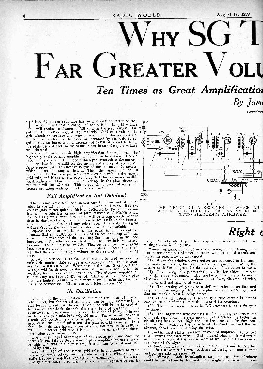
FIG. 1THE CIRCUIT OF A RECEIVER IN WHICH AN /SCREEN GRID TUBE IS USED AS AN EFFECTP
RADIO FREQUENCY AMPLIFIER.
Right(1)-Radio broadcasting or telephony is impossible without trans-
mitting the carrier frequency.(2)-A resistance connected across a tuning coil or tuning con-
denser introduces a resistance in series with the tuned circuit andlowers the selectivity of that circuit.
(3) -When the relative power output are compared in transmis-sion units or decibels, the zero level is zero power. That is, thenumber of decibelg express the absolute value of the power in watts.
(4)-Two tuning coils geometrically similar but differing in sizehave the same inductance. The similarity must apply to everydimension of the coil, such a diameter of form, diameter of wire,length of coil and spacing of wire.
(5)-The heating of plates to a dull red color in rectifier andamplifier tubes indicates that the applied voltage is too high andthat too much current is being drawn.
(6)-The amplification in a screen grid tube circuit is limitedonly by the size of the plate resistance used for coupling.
(7)-The most frequent hum in AC receivers is of a 60 -cyclefrequency.
(8)-The larger the time constant of the stopping condenser andgrid leak resistance in a resistance -coupled amplifier the better thecircuit amplifies on both high and low frequencies. The time con-stant is the product of the capacity of the condenser and the re-sistance, farads and ohms being the units.
(9)-The most stable transformer -coupled amplifier having twotransformers and three tubes is that obtained when the transformersare connected so that the transformers as well as the tubes reversethe phase of the signal.
(10)-A full wave rectifier takes more power from the AC linethan a half wave rectifier when both are delivering the same currentand voltage into the same load.
(1)-Wrong. Both broadcasting and point-to-point telephonycould be carried on by transmitting a single side band. Trans-

August 17, 1929 RADIO WORLD 5
JBES PROVIDE
1E AND BETTER TONEasily Obtainable in Practicer. Carrollfor
eliminated from the circuit and still leave a greater signal gainwhen one SG tube replaces two others. This naturally reduceswave form distortion, for the more tubes in the audio amplifier.the more distortion, as a rule.
In the radio frequency amplifier the low plate -to -grid capacityof the tube resulted in stability. In the audio amplifier it resultsin better frequency response when the tube is used in a resistancecoupled amplifier. In the three -electrode tube the plate -to -gridcapacity results in a lower amplification of the 'higher audio notes.In the screen grid tube this frequency distortion is much less.The practical effect of this is that the output from a resistancecoupled screen grid amplifier will be more distinct than that froma similar circuit having three -electrode tubes. The consonants inspeech will be more easily distinguishable, especially the sibilants.As far as music goes there will be no appreciable frequency differ-ence.
Proper Voltage NecessarySo that best results may be obtained from a screen grid tube
it is necessary that the proper voltages be used. This applies to theplate voltage, the screen grid voltage, and the grid bias. If theplate return lead be connected to a certain tap on the B supplyunit there is no definite assurance that the voltage be correct,, be-cause there may be resistances in the circuit which *ill lower thevoltage,below that which the tube should have for the plate loadand the screen Voltage actually employed. Also, if the screen re-turn be connected to another tap on the B supply, there is no as -
gong?oceanic telephony is carried on with such a scheme. Broadcastingis not because receivers are not suitable for the system.
(2)-Right. The higher the resistance connected across thetuned cricuit the less is the equivalent series resistance in the tunedcircuit. A small resistance across the tuned circuit introduces a veryhigh series resistance.
(3)-Wrong. It is impossible to' compare zero' relatively to 'anyfinite quantity. The zero level of power is always some arbitrarypower greater than zero."
(4)-Wrong. If two 'tuning coils are exactly similar geometric-ally, differing only in their dimensions, the inductances are propor-tional to the dimensions. For example, if every dimension of oneof the coils is n times as great as the corresponding dimension ofthe other, then the inductance of one coil is n times as great as thatof the other. This follows from the fact that the dimension of in-ductance is that of a length.
(5)-Right. The heating of the plate is due to the bombardmentof electrons on the plate. Every electron contributes some heat.If enough electrons reach the plate every second, the plate will getred hot.
(6)-Wrong. Theoretically it is true provided that the appliedplate voltage is high enough. Practically, the amplification is limitedby the, plate battery voltage used.
(7)-Wrong. The most frequent hum has a frequency of 120cycles.
(8)-Right. There is nothing in the idea that the time constantshould be small in order to amplify the high frequencies, becausethe condenser does not charge up.
(9)-Right. When both transformers as well as the tubes reversethe phase, the feed back through the common impedance is such asto decrease the amplification in every tube.
(10)-Wrong. The half wave rectifier takes more power underthe conditions because its regulation is poorer. That is, its internalresistance is higher and power must be taken from the line to supplythe losses. However, there is very little difference.
surance that the screen voltage will be ,:orrect. There should beno impedance at all in the screen circuit. If one is used for steady-ing the voltage applied, there must be an adequate by-pass con-denser to reduce the impedance to zero with respect to the . fre-quencies at which the tube is operating. This use of by-pass con-densers is illustrated in Fig. 1 which shows an AC -screen gridtube used as a radio frequency amplifier. The plate Load on .thistube is mainly the resistance reflected back into the primary fromthe tuned circuit. This may well be of the order of 100,000 ohmsif the circuit is selective and if the primary and secondary arecoupled closely.
Hum EliminationUM is present in my AC receiver, which I built myself. Itwas not there before. PIease give me some advice on' elimi-nation of hum. ---H. E. R. Remove the detector tube, withthe rest of the tubes in' operation, as hum arising in the audio 'am-plifier would persist under those circumstances. If the hum dis-appears when ,the detector tube is removed, then the hum may beascribed to the detect-T or the radio frequency amplifier. If thehum seems to be in the radio frequency amplifier, make sure thatself -oscillation is not present, and that the AC 110 -volt cable doesnot run near the radio tubes. If grid bias detection is used, experi-
ment with different values of bias, as the detector may be workinginefficiently, and the hum component may be greater than the signaloutput. Test the bias on all tubes. If a voltage drop in a resistorfurnishes the bias, use higher and lower values of resistance, oralter the plate current. If the hum seems to be in the audio ampli-fier it may be due to audio regenerative effects that produce over-stressed amplification in the region of the hum frequency, which isnormally strongest at 120 cycles, the second' harmonic of the funda-mental 60 -cycle frequency. Ground the negative lead of the elimina-tor directly, not through a condenser, as the voltage drop -in sucha series condenser may produce hum. With the full set' in opera-tion, short one of the filter choke coils and listen to determineif' hum increases. It is a good sign if the hum does increase.If it does not, the choke may be shorted. If you suspect a shortcircuit there, measure the voltage at the output of the rectifiertube and again at the point where the two chokes are joined.It should be less- at the joint, due to the voltage drop in the firstchoke. If it is not' less, and if thethehum does not change in in-tensity when first choke is shorted, then that choke is de-fective: Try the same test on the second choke. If more cur-rent is passed through the filter system than should be thecase, remove the power tube and listen, with speaker or ear-phones, at the output of the first audio tube. The relative humshould be considered, not the absolute value, since the signal levelis lower. A disproportionate reduction in hum would indicatethe overloading has been corrected, since the heavy plate cur-rent drain of the power tube has been removed, so another smallchoke may be added to the series, not only for better filtrationbut also to reduce the voltage a little. One precaution to re-meber is that some tubes produce hum when the plate currentis lower than it should be, so increase the plate current on pre-liminary audio tubes as a test. In directly heated AC filament cir-cuits of tubes the electrical center must be accurately establishedto avoid hum, so try a center -tapped resistor, or a fixed resistorwith a movable center tap, across the filament of the last audiotube or tubes, with grid return to the center tap. Sometimes humarises from acoustical coupling between speaker and audio ampli-fier or speaker and AC line or coupling of all three. If pos-sible, move the speaker to some different angle or farther awayfrom the set. See that the aerial does not run near telephonelines and the like, or, if it must be only a few feet away from them,that it runs at right angles to them. Put an AF choke coil in se-ries with the B plus detector lead, between the B plus end ofthe audio transformer primary or other coil or resistor in the platecircuit, and put a 2 mfd. condenser from this end of the plate cir-cuit to ground.

6 RADIO WORLD August 17, 1929
FIG. 62
CHARACTERIS'Curves Predict Performance of 22
By J. E. Ander,
Ea
FIG. 63FIG. 62-DIAGRAM OF CIRCUIT FOR TAKING GRID V OLTAGE, PLATE CURRENT CURVES ON A BATTERY
HEATED TUBE OF THE THREE ELEMENT TYPEFIG. 63-DIAGRAM OF A CIRCUIT FOR TAKING CHARA CTERISTIC CURVES ON A HEATER TYPE TUBE HAVING
THREE ELEMENTSFIG. 64-CIRCUIT ARRANGEMENT FOR TAKING CHARACTERISTIC CURVES ON A THREE ELEMENT TUBE
HEATED DIRECTLY WITH ACFIG. 65-CIRCUIT FOR TAKING CHARACTERISTIC CURVES ON A BATTERY TYPE SCREEN GRID TUBE
FIG. 66-WHEN TAKING CHARACTERISTIC CURVES 0 N A HEATER TYPE SCREEN GRID TUBE A CIRCUIT OFTHIS KIND IS SUITABLE
FIG. 67-CIRCUIT DIAGRAM OF A VACUUM VOLTMETER IN WHICH THE UNKNOWN VOLTAGE ISBALANCED AGAINST A KNOWN VOLTAGE. THIS CIRCUIT CAN BE USED FOR MEASURING THE VOLTAGE
DROP IN HIGH RESISTANCES
CAP
110 ihpM111Ea
ADO 8
FIG. 64
[The following article is the twelfth. consecutive one in the serieson "Power Amplifiers," by J. E. Anderson and Herman Bernard.The series was started in the June 1st issue. Next week the charac-teristics of other tubes will be discussed, completing the subject ofcharacteristics, and comprising the remainder of the family of tubesin use *today in audio amplifiers, including sound reproduction fortheatres.-Editor.]
* * *
This calculation does not take into account the losses in the trans-former windings and the core. A loss of 20 per cent. may be as-sumed for ordinary transformers used in radio receivers and platevoltage supply units. Making this allowance the power becomes26.25 watts.
The total power required by the plate circuits and the platevoltage supply unit, exclusive of the filament power, can be takenas equal to the effective AC voltage across one half of the highvoltage winding on open cricuit, that is, rated voltage, and the totaldirect current flowing the B supply circuit. This current mightbe measured in the lead to the mid tap of the high voltage winding.The total current is used in order to take into account not onlythe plate currents but also the bleeder current. The rated voltage,or the voltage measured when no direct current flows, is used inorder to take into account losses in the high voltage winding andthe choke coils.
Suppose the total direct current is 80 milliamperes and that thevoltage across each half of the high voltage winding is 350 volts.The power then is .08x350, or 28 watts. This does not take intoaccount the core losses associated with the high voltage winding,but it does take into account the copper losses. Since iron andcopper losses in a transformer are about equal, we add .10 per cent.to the 28 watts. Hence the total power required by the direct -current portion of the circuit is 30.8 watts.
Since the filament power was 2625 watts and the plate power is30.8 watts, the total power dissipation in the circuit is nearly 37watts. This is the amount that is taken from the power line. Fromthis it is possible to compute the cost per hour of operation. Forexample, if electrical energy costs 7.5 cents per kilowatt-hour, thecost per hour is 7.5x.037, or .2775 cent.
The alternating current in the primary, or the sum of the currentsin the primaries if several transformers are used, is obtained ap-proximately by dividing the power by the line voltage. Supposethe line voltage is 115 volts. Then the current is .322 ampere. Thisdivision assumes that the power factor of the transformer is unity.Actually it is slightly less than unity, so that the primary currentwould be slightly higher.
If a one ampere fuse be inserted in the line so that all the primarycurrent, regardless of the number of transformers used in theamplifier, flows through fuse, there will be ample protection,
FIG. 65 FIG. 67
for if any of the windings in the secondary becomes short-circuitedthe fuse will blow.
If the alternating current in the primary be measured with an ACammeter and then multipled with the line voltage, an approximatevalue of the total power required will be obtained. This method ismore direct than the other and gives the current directly. Thepower thus obtained neglects the power factor of the transformer,but even so the result may be more accurate than the indirectmethod.
Curves showing the relationship between the plate currentand grid voltage are very useful for determining the properoperating grid bias and for estimating the performance of tubesand circuits under given conditions. Such curves are not avail-able for all tubes, and those curves that are avaliable are foraverage tubes and so-called normal operating plate voltages.Therefore it is often necessary to take the curves.
For this purpose suitable circuit arrangements are required,and they differ somewhat according to the type of tube that isto be studied. In Figs. 62 to 66, inclusive, are given such cir-cuits for five different types of tubes. hile a resistance R1is shown in each of these circuits, it is sometimes desirable totake curves when there is no resistance or other impedance inthe grid circuit. R1 then is simply short circuited. R1 repre-sents the grid leak resistance or the resistance of the secondaryof the coupling transformer.
In each plate circuit is also shown a resistance R2, which maybe a pure resistance or the resistance of the primary of atransformer or choke coil. Sometimes it is desirable to take acurve on the tube alone, without any load impedance. R2 isthen short circuited.
The meter M in each of these circuits is a milliammeter ofa range suitable to the type of tube studied, the plate batteryvoltage used, and the amount of resistance in the plate circuit.For a resistance -coupled circuit the range may be 0-1 milliam-pere and for a 250 power tube it may be 0-100 milliamperes.The plate current flowing when the grid bias is zero usuallydetermines the range, since there is no particular reason fortaking observations for positive grid voltages.
Before taking any observations on plate current with any ofthese arrangements, the filament terminal voltage should beadjusted to the normal value for the tube studied, using forthis purpose a suitable low range voltmeter. For battery -heatedtubes the filament terminal voltage is best adjusted by meansof a rheostat Rh, in Figs. 62 and 65, and for AC tubes it canbe adjusted by means of a rheostat in the primary of thesupply transformer. The voltmeter, which is not shown in anyof the circuits, should be connected directly across the filamentterminals on the socket, or as near the socket as practicable.

August 17, 1929 RADIO WORLD 7
'S OF TUBESrO, 201A, 112 and 171A Valvesd Herman Bernard
(0, 600t --_J° 500
400
311100
a. 200
100
0
2d1 -A
112
--226
/e.-227
15 10 5 0 5 10 15 20PERCENT UNBALANCE
FIG. 68.CURVES SHOWING THE RELATION BETWEEN HUMVOLTAGE IN THE PLATE CIRCUITS OF TUBESHEATED WITH AC AND THE PERCENTAGE UNBAL-ANCE OF GRID RETURN TO THE FILAMENT OR
HEATER,
The plate battery voltage is applied at the terminals indicatedand measured with voltmeter V2. The connection of this metershould be as indicated in each instance. The plate batteryvoltage should be adjusted to the value at which a grid voltage,plate current curve is desired, and the voltage selected .shouldbe held reasonably constant during the run. If a fresh batteryis used throughout the voltage will not change during a run.If the plate voltage is obtained from a battery eliminator thevoltage will change, and for that reason this kind of supply isnot recommended.
In the two circuits for screen grid tubes, namely, Figs. 65 and66, an additional voltage for the screen is required, measuredwith meter V3. The positive terminal for the screen grid voltageis indicated by D. The source of the screen grid voltage maybe either a part of the plate battery, or a separate battery.
The grid bias applied is measured with voltmeter Vl. It isimportant that this meter be connected in each instance ex-actly as shown, for otherwise it will not measure _the gridvoltage applied, and the meter should be left connected whiletaking every plate current reading.
The grid voltage applied is derived from a battery Eg, whichshould contain taps so that the voltage across the voltmetercan be varied in steps of about 3 volts or less. Across a por-tion of the grid battery, say about 4.5 volts, is connected a po-tentiometer P of about 2,000 ohms for adjusting the voltagein minute steps. While this potentiometer is not absolutelynecessary in all instances, it is always convenient for adjustingthe voltage to correspond exactly with the scale divisions onthe meter. This facilitates plotting the curves.
Occasions arise when the plate current is so small that it isimpossible accurately to measure it with ordinary meters avail-able, yet the voltage drop in the plate load resistance is ofconsiderable magnitude. Examples are the taking of curves onresistance -coupled amplifiers with resistances of the order of1.0 meg. in the plate circuit and the taking of curves for gridbias values so high that the current is practically zero. In suchinstances the simplest way of obtaining the curves is to measurethe voltage drop across the plate load resistance by means ofa vacuum tube voltmeter.
One vacuum tube voltmeter arrangement is shown in Fig. 67.This is particularly convenient because it imposes no rigid re-quirements on the voltmeter circuit. The filament voltage onthe voltmeter tube need not be kept at a specified value, just soit keeps constant for a few moments. The meter need not becalibrated. Neither does the plate voltage have to be constantfor long periods. The indicating meter M in the plate circuitmay be of the usual rugged type. The tube itself should prefer-ably be one having a high mutual conductance, such as the
600(f)
500
:3 400_J
300
100200
0
0
-4- 2 01- AEc - 6Ei = 4.5
Ec -6Ef 1.5
1 2
E0- 6Ef =4.5
226-n
2 4 6 8 10 12 14 16PLATE CURRENT (111A)
FIG. 69.CURVES SHOWING THE RELATIONSHIP BETWEENTHE HUM VOLTAGE IN THE PLATE CIRCUITS AND
THE AMOUNT OF PLATE CURRENT,
171A. The voltmeter V by means of which the unknown voltageis measured indirectly need not be one of high sensitivity. Itmay be any ordinary voltmeter having a range sufficient for thevoltage to be measured.
The meter essentially employs the null method. The effect ofthe unknown voltage in the grid circuit of the voltmeter tubeis balanced against another voltage introduced in seriesand in the opposite direction. This bucking voltage is the dropacross the voltmeter V, the value of which is directly indicated.
The current necessary to operate the voltmeter V is takenfrom the battery serving the voltmeter tube, through a variablehigh resistance Rhl. When this is adjusted to a value muchgreater than the internal resistance of the voltmeter the voltageacross the meter is small, and when the resistance in Rhl iszero the entire battery voltage is across the voltmeter. Hencethe range of this vacuum tube voltmeter is limited only by therange of V, or by the voltage applied to the tube. It is notpossible to increase Rhl to such a value that the voltmeter Vreads zero, because that would require an infinite resistance.For this reason it is clear that a voltmeter of low internal re-sistance is preferable to one having a high resistance per volt.
In using this vacuum tube voltmeter, the first step is toestablish a reference point on the indicator meter M. Thedouble pole, double throw switch is thrown to the right andthe single pole, double throw switch SS is thrown down. Thismakes a direct lead from the grid of the tube to the minus sideof the filament battery. The voltmeter V is short circuited butthe grid remains negative by the drop in R. This bias isneeded to prevent any grid current when a reading is taken.
Next the rheostat Rh2 is adjusted until the meter M readsany convenient value. In order that any deviation from thisreading may be detected the rheostat should be adjusted so thatthe needle on the meter points exactly to a division line on thescale of M. This reading is the reference point, or null point.
When this point has been established, the double throw, doublepole switch DS is thrown to the left to make contact with theterminals Ex, across which the unknown voltage is connected withthe polarity as indicated. This makes the grid of the tube negative,and the plate current decreases. Next switch SS is thrown up soas to connect with the line coming from Rhl. This impresses abucking voltage on the grid, increasing the plate current. Thesetting of Rhl is then adjusted until the needle on the meter M isbrought back exactly to the reference point. The reading onvoltmeter V then indicates the value of the unknown voltage acrossthe terminals Ex. At the beginning Rhl must be set at itshighest value to protect M as well as the tube.
In a series of readings it is not necessary to check the referencepoint before every reading, unless there is reason to suppose thatsomething in the circuit has changed.
If it is required to measure voltages higher than the voltage ap-
RADIO WORLD August 17, 1929
LOAD ON ATUBEHigh Impedance Required for High Mu Valve
00 20 40 60 80 100 120 140 160 180 200 220 249 260 280 300 32o
VOLTAGE ON PLATE.
,- uXEf
-2405.0 0
oi 4.)
i
4. (0 0?)
4)'%h
p, 41
).' "0
4,)
:910
2 OF 414.
.3 4
, _-,
/9 <14,c.,
' 5 in -E--- 4'''' 4, n9
.3 rn .Cl. -._......orr-
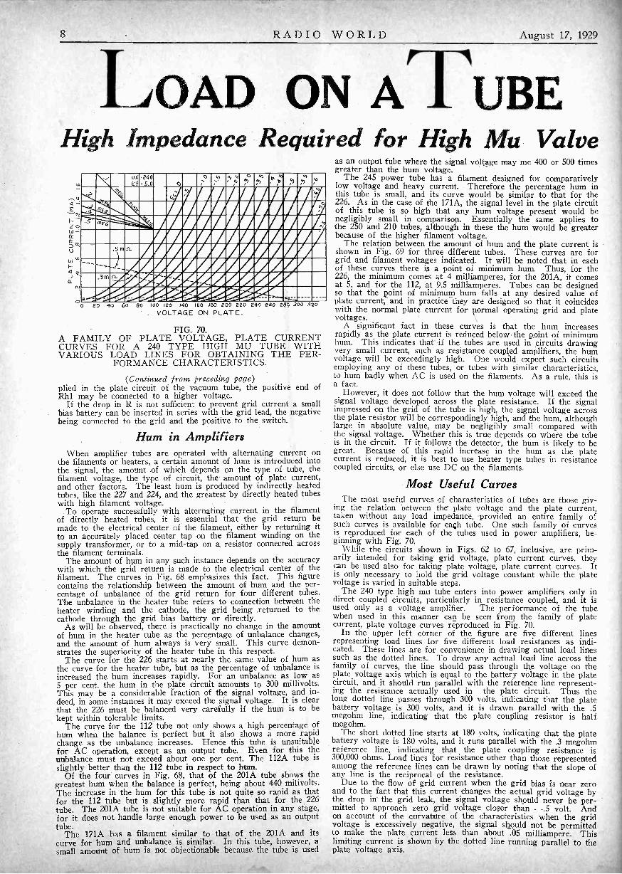
FIG. 70.A FAMILY OF PLATE VOLTAGE, PLATE CURRENTCURVES FOR A 240 TYPE HIGH MU TUBE WITHVARIOUS LOAD LINES FOR OBTAINING THE PER-
FORMANCE CHARACTERISTICS.
(Continued from preceding page)plied in the plate circuit of the vacuum tube, the positive end ofRhl may be connected to a higher voltage.
If the drop in R is not sufficient to prevent grid current a smallbias battery can be inserted in series with the grid lead, the negativebeing connected to the grid and the positive to the switch.
Hum in AmplifiersWhen amplifier tubes are operated with alternating current on
the filaments or heaters, a certain amount of hum is introduced intothe signal, the amount of which depends on the type of tube, thefilament voltage, the type of circuit, the amount of plate current,and other factors. The least hum is produced by indirectly heatedtubes, like the 227 and 224, and the greatest by directly heated tubeswith high filament voltage.
To operate successfully with alternating current in the filamentof directly heated tubes, it is essential that the grid return bemade to the electrical center of the filament, either by returning itto an accurately placed center tap on the filament winding on thesupply transformer, or to a mid -tap on a resistor connected acrossthe filament terminals.
The amount of hum in any such instance depends on the accuracywith which the grid return is made to the electrical center of thefilament. The curves in Fig. 68 emphasizes this fact. This figurecontains the relationship between the amount of hum and the per-centage of unbalance of the grid return for four different tubes.The unbalance in the heater tube refers to connection between theheater winding and the cathode, the grid being returned to thecathode through the grid bias battery or directly.
As will be observed, there is practically no change in the amountof hum in the heater tube as the percentage of unbalance changes,and the amount of hum always is very small. This curve demon-strates the superiority of the heater tube in this respect.
The curve for the 226 starts at nearly the same value of hum asthe curve for the heater tube, but as the percentage of unbalance isincreased the hum increases rapidly. For an unbalance as low as5 per cent. the hum in the plate circuit amounts to 300 millivolts.This may be a considerable fraction of the signal voltage, and in-deed, in some instances it may exceed the signal voltage. It is clearthat the 226 must be balanced very carefully if the hum is to bekept within tolerable limits.
The curve for the 112 tube not only shows a high percentage ofhum when the balance is perfect but it also shows a more rapidchange as the unbalance increases. Hence this tube is unsuitablefor AC operation, except as an output tube. Even for this theunbalance must not exceed about one per cent. The 112A tube isslightly better than the 112 tube in respect to hum.
Of the four curves in Fig. 68, that of the 201A tube shows thegreatest hum when the balance is perfect, being about 440 milivolts.The increase in the hum for this tube is not quite so rapid as thatfor the 112 tube but is slightly more rapid than that for the 226tube. The 201A tube is not suitable for AC operation in any stage,for it does not handle large enough power to be used as an outputtube.
The 171A has a filament similar to that of the 201A and itscurve for hum and unbalance is similar. In this tube, however, asmall amount of hum is not objectionable because the tube is used
as an output tube where the signal voltage may me 400 or 500 timesgreater than the hum voltage.
The 245 power tube has a filament designed for comparativelylow voltage and heavy current. Therefore the percentage hum inthis tube is small, and its curve would be similar to that for the226, As in the case of the 171A, the signal level in the plate circuitof this tube is so high that any hum voltage present would benegligibly small in comparison. Essentially the same applies tothe 250 and 210 tubes, although in these the hum would be greaterbecause of the higher filament voltage.
The relation between the amount of hum and the plate current isshown in Fig. 69 for three different tubes. These curves are forgrid and filament voltages indicated. It will be noted that in eachof these curves there is a point of minimum hum. Thus, for the226, the minimum comes at 4 milliamperes, for the 201A, it comesat 5, and for the 112, at 9.5 milliamperes. Tubes can be designedso that the point of minimum hum falls at any desired value ofplate current, and in practice they are designed so that it coincideswith the normal plate current for normal operating grid and platevoltages.
A significant fact in these curves is that the hum increasesrapidly as the plate current is reduced below ,the point of minimumhum. This indicates that if the tubes are used in circuits drawingvery small current, such as resistance coupled amplifiers, the humvoltage will be exceedingly high. One would expect such circuitsemploying any of these tubes, or tubes with similar characteristics,to hum badly when AC is used on the filaments. As a rule, this isa fact.
However, it does not follow that the hum voltage will exceed thesignal voltage developed across the plate resistance. If the signalimpressed on the grid of the tube is high, the signal voltage acrossthe plate resistor will be correspondingly high, and the hum, althoughlarge in absolute value, may be negligibly small compared withthe signal voltage. Whether this is true depends on where the tubeis in the circuit. If it follows the detector, the hum is likely to begreat. Because of this rapid increase in the hum as the platecurrent is reduced, it is best to use heater type tubes in resistancecoupled circuits, or else use DC on the filaments.
Most Useful CurvesThe most useful curves of charasteristics of tubes are those giv-
ing the relation between the plate voltage and the plate current,taken without any load impedance, -provided an entire family ofsuch curves is available for each tube. One such family of curvesis reproduced for each of the tubes used in power amplifiers, be-ginning with Fig. 70.
While the circuits shown in Figs. 62 to 67, inclusive, are prim-arily intended for taking grid voltage, plate current curves, theycan be used also for taking plate voltage, plate current curves. Itis only necessary to hold the grid voltage constant while the platevoltage is varied in suitable steps.
The 240 type high mu tube enters into power amplifiers only indirect coupled circuits, particularly in resistance coupled, and it isused only as a voltage amplifier. The performance of the tubewhen used in this manner can be seen from the family of platecurrent, plate voltage curves reproduced in Fig. 70.
In the upper left corner of the figure are five different linesrepresenting load lines for five different load resistances as indi-cated. These lines are for convenience in drawing actual load linessuch as the dotted lines. To draw any actual load line across thefamily of curves, the line should pass through the voltage on theplate voltage axis which is equal to the battery voltage in the platecircuit, and it should run parallel with the reference line represent-ing the resistance actually used in the plate circuit. Thus thelong dotted line passes through 300 volts, indicating that the platebattery voltage is 300 volts, and it is drawn parallel with the .5megohm line, indicating that the plate coupling resistor is halfmegohm.
The short dotted line starts at 180 volts, indicating that the platebattery voltage is 180 volts, and it runs parallel with the .3 megohmreference line, indicating that the plate coupling resistance is300,000 ohms. Load lines for resistance other than those representedamong the reference lines can be drawn by noting that the slope ofany line is the reciprocal of the resistance.
Due to the flow of grid current when the grid bias is near zeroand to the fact that this current changes the actual grid voltage bythe drop in the grid leak, the signal voltage should never be per-mitted to approach zero grid voltage closer than -,5 volt. Andon account of the curvature of the characteristics when the gridvoltage is excessively negative, the signal should not be permittedto make the plate current less than about .05 milliampere. Thislimiting current is shown by the dotted line running parallel to theplate voltage axis.

August 17, 1929 RADIO WORLD 9
AN A B C SUPPLYfor 224, 227 and 245 Tubes, up to Eight
[The first instalment of this article on the construction of anABC supply for 224, 227 and 245 tubes, was published last week.The final instalment follows. The supply furnishes all filament,plate and grid voltages. The total number of heater type tubes -224and 227- should not exceed six. The 245 may be used singly orin push-pull. For push-pull connect a 1,500 -ohm 10 -watt resistorbetween points (1) and (4). The maximum drain should not ex-ceed 100 milliamperes. An 8 -tube set should not draw more thanthat.-Editor.]
* * *
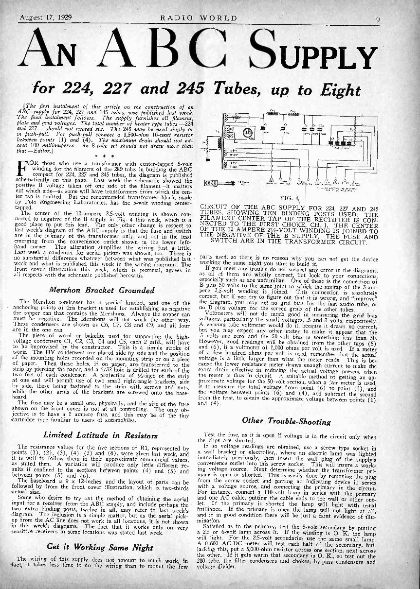
FOR those who use a transformer with center -tapped 5 -voltwinding for the filament of the 280 tube, in building the ABCcompact for 224, 227 and 245 tubes, the diagram is published
schematically on this page. Last week the schematic showed thepositive B voltage taken off one side of the filament-it mattersnot which side-as some will have transformers from which the cen-ter tap is omitted. But the recommended transformer block, madeby Polo Engineering Laboratories, has the 5 -volt winding center-tapped.
The center of the 12 -ampere 2.5 -volt winding is shown con-nected to negative of the B supply in Fig. 4 this week, which is agood place to put this lead. The only ,other change is respect tolast week's diagram of the ABC supply is that the fuse and switchare in the primary of the transformer only, and not in the leademerging from the convenience outlet shown in the lower left-hand corner. This alteration simplifies the wiring just a little.Last week a condenser for aerial pickup was shown, too. There isno substantial difference whatever between what was published lastweek and what is published this week in the wiring diagrams. Thefront cover illustration this week, which is pictorial, agrees inall respects with the schematic published herewith.
Mershon Bracket GroundedThe Mershon condenser has a special bracket, and one of the
anchoring points of this bracket is used for establishing as negativethe copper can that contains the Mershons. Always the copper canmust be negative. The Mershons will not work the other way.These condensers are shown as C6, C7, C8 and C9, and all fourare in the one can.
The piece of wood or bakelite used for supporting the high-voltage condensers Cl, C2, C3, C4 and C5, each 2 mfd., will haveto be improvised by the constructor. This is a simple stroke ofwork. The HV condensers are placed side by side and the position.of the mounting holes recorded on the mounting strip or on a pieceof paper. Then these holes, if on paper, are transferred to thestrip by piercing the paper, and a 6/32 hole is drilled for each of the-two feet of each condenser. A projection of IA -inch of the stripat one end will permit use of two small right-angle brackets, sideby side, these being fastened to the strip with screws and nuts,while the other arms of the brackets are screwed onto the base-board.
The fuse may be a small one, physically, and the size of the fuseshown on the front cover is not at all controlling. The only ob-jective is to have a 1 ampere fuse, and this may be of the tinycartridge type familiar to users of automobiles.
Limited Latitude in ResistorsThe resistance values for the five sections of R1, represented by
-points (1), (2), (3), (4), (5) and (6), were given last week, andit is well to follow them in their approximate commercial values,as stated then. A variation will produce only little different re-sults if confined to the sections between points (4) and (5) andbetween points (5) and (6).
The baseboard is 9 x 12 -inches, and the layout of parts can befollowed by from the front cover illustration, which is two-thirdsactual size.
Some who desire to try out the method of obtaining the aerialinput for a receiver from the ABC supply, and include perhaps thetwo extra binding posts, twelve in all, may refer to last week'sAiagram. The inclusion is a simple matter, but as the aerial pick--up from the AC line does not work in all locations, it is not shownin this week's diagrams. The fact that it works only on very-sensitive receivers in some locations was stated last week.
Get it Working Same NightThe wiring of this supply does not amount to much work, in
-fact, it takes less time to do the wiring than to mount the few
C
ama. I2m,a.
a 6,
JOh i "°;.e -c5
,...g.,w.,. ,..f.*:.i, ,,At -.. f,;1.,F.a., '' " 4:1.`.'
FIG. 4CIRCUIT OF THE ABC SUPPLY FOR 224, 227 AND 245TUBES, SHOWING TEN BINDING POSTS USED. THEFILAMENT CENTER TAP OF THE RECTIFIER IS CON-NECTED TO THE FIRST CHOKE, CH. 1. THE CENTEROF THE 12 AMPERE 2% -VOLT WINDING IS JOINED TOTHE NEGATIVE OF THE B SUPPLY. THE FUSE AND
SWITCH ARE IN THE TRANSFORMER CIRCUIT.
parts used, so there is no reason why you can not get the deviceworking the same night you start to build it.
If you meet any trouble do not suspect any error in the diagrams,as all of them are wholly correct, but look to your connections,especially such as are unfamiliar. One of these is the connection ofB plus 50 volts to the same joint to which the midtap of the 3 -am-pere 2.5 -volt winding is joined. This connection is absolutelycorrect, but if you try to figure out that it is wrong, and "improve"the diagram, you may get no grid bias for the last audio tube, orno B plus voltage for the screen grids of the other tubes.
Voltmeters will not do much good in measuring the grid biasvoltages, particularly the small voltages, .5 and 2 volts, respectively.A vacuum tube voltmeter would do it, because it draws no current,but you may expect any 'other meter to make it appear that the.5 volts are zero and the 50 -volt bias is something less than 50.However, good readings will be obtained from the other taps (5)and (6), if a voltmeter of 1,000 ohms per volt is used. If a meterof a few hundred ohms per volt is used, remember that the actualvoltage is a little larger than what the meter reads. This is be-cause the lower resistance meter draws enough current to make theextra drain effective in reducing the actual voltage present whenthe meter is thus in circuit. A suitable method of getting an ap-proximate voltage for the 50 -volt section, when a fair meter is used,is to measure the total voltage from point (6) to point (1), andth voltage between points (6) and (4), and subtract the secondfrom the first, to obtain the approximate voltage between points (1)and (4).
Other Trouble -Shooting
Test the fuse, as it is open if voltage is in the circuit only whenthe clips are shorted.If no voltage readings are obtained, use a screw type socket in
a wall bracket or electrolier where an electric lamp was lightedimmediately previously, then insert the wall plug of the supply'sconvenience outlet into this screw socket. This will insure a work-ing voltage source. Next determine whether the transformer pri-mary is open or shorted. This is easily done by removing the plugfrom the screw socket and putting an indicating device in serieswith a voltage source, and connecting the primary in the circuit.For instance, connect a 110 -volt lamp in series with the primaryand one AC cable, putting the cable ends to the wall or other out-let. If the primary is shorted the lamp will light with usualbrilliance. If the primary is open the lamp will not light at all,and if in good condition there will be just a faint evidence of illu-mination.
Satisfied as to the primary, test the 5 -volt secondary by puttinga 2.5 or 6 -volt lamp across it. If the winding is 0. K. the lampwill light. For the 2.5 -volt secondaries use the same small lamp.A 0-600 AC -DC meter will test each half of the secondary, but,lacking this, put a 5,000 -ohm resistor across one section, next acrossthe other. If it gets warm that secondary is 0. K., so test out the280 tube, the filter condensers and chokes, by-pass condensers andvoltage divider.

RADIO WORLD August 17, 1929
LOAD ON A UBEHigh Impedance Required for High Mu Valve
O
..., UX -240Ef 5.0 0
oi
4>
i4 (0
,0
r6)4)
, )D, 4), 0./ 4)
r
.044 '°
-2, .0.4
:3
/,'''
.5 DI St.
.._
. 3 fit fl. ." . - -
..,....e..""- _
0 20 40 60 80 100 120 140 160 180 200 220 240 260 280 .300 320. VOLTAGE ON PLATE.
FIG. 70.A FAMILY OF PLATE VOLTAGE, PLATE CURRENTCURVES FOR A 240 TYPE HIGH MU TUBE WITHVARIOUS LOAD LINES FOR OBTAINING THE PER-
FORMANCE CHARACTERISTICS.
(Continued from preceding page)plied in the plate circuit of the vacuum tube, the positive end ofRhl may be connected to a higher voltage.
If the drop in R is not sufficient to prevent grid current a smallbias battery can be inserted in series with the grid lead, the negativebeing connected to the grid and the positive to the switch.
Hum in AmplifiersWhen amplifier tubes are operated with alternating current on
the filaments or heaters, a certain amount of hum is introduced intothe signal, the amount of which depends on the type of tube, thefilament voltage, the type of circuit, the amount of plate current,and other factors. The least hum is produced by indirectly heatedtubes, like the 227 and 224, and the greatest by directly heated tubeswith high filament voltage.
To operate successfully with alternating current in the filamentof directly heated tubes, it is essential that the grid return bemade to the electrical center of the filament, either by returning itto an accurately placed center tap on the filament winding on thesupply transformer, or to a mid -tap on a resistor connected acrossthe filament terminals.
The amount of hum in any such instance depends on the accuracywith which the grid return is made to the electrical center of thefilament. The curves in Fig. 68 emphasizes this fact. This figurecontains the relationship between the amount of hum and the per-centage of unbalance of the grid return for four different tubes.The unbalance in the heater tube refers to connection between theheater winding and the cathode, the grid being returned to thecathode through the grid bias battery or directly.
As will be observed, there is practically no change in the amountof hum in the heater tube as the percentage of unbalance changes,and the amount of hum always is very small. This curve demon-strates the superiority of the heater tube in this respect.
The curve for the 226 starts at nearly the same value of hum asthe curve for the heater tube, but as the percentage of unbalance isincreased the hum increases rapidly. For an unbalance as low as5 per cent. the hum in the plate circuit amounts to 300 millivolts.This may be a considerable fraction of the signal voltage, and in-deed, in some instances it may exceed the signal voltage. It is clearthat the 226 must be balanced very carefully if the hum is to bekept within tolerable limits.
The curve for the 112 tube not only shows a high percentage ofhum when the balance is perfect but it also shows a more rapidchange as the unbalance increases. Hence this tube is unsuitablefor AC operation, except as an output tube. Even for this theunbalance must not exceed about one per cent. The 112A tube isslightly better than the 112 tube in respect to hum.
Of the four curves in Fig. 68, that of the 201A tube shows thegreatest hum when the balance is perfect, being about 440 milivolts.The increase in the hum for this tube is not quite so rapid as thatfor the 112 tube but is slightly more rapid than that for the 226tube. The 201A tube is not suitable for AC operation in any stage,for it does not handle large enough power to be used as an outputtube.
The 171A has a filament similar to that of the 201A and itscurve for hum and unbalance is similar. In this tube, however, asmall amount of hum is not objectionable because the tube is used
as an output tube where the signal voltage may me 400 or 500 timesgreater than the hum voltage.
The 245 power tube has a filament designed for comparativelylow voltage and heavy current. Therefore the percentage hum inthis tube is small, and its curve would be similar to that for the226. As in the case of the 171A, the signal level in the plate circuitof this tube is so high that any hum voltage present would benegligibly small in comparison. Essentially the same applies tothe 250 and 210 tubes, although in these the hum would be greaterbecause of the higher filament voltage.
The relation between the amount of hum and the plate current isshown in Fig. 69 for three different tubes. These curves are forgrid and filament voltages indicated. It will be noted that in eachof these curves there is a point of minimum hum. Thus, for the226, the minimum comes at 4 milliamperes, for the 201A, it comesat 5, and for the 112, at 9.5 milliamperes. Tubes can be designedso that the point of minimum hum falls at any desired value ofplate current, and in practice they are designed so that it coincideswith the normal plate current for normal operating grid and platevoltages.
A significant fact in these curves is that the hum increasesrapidly as the plate current is reduced below the point of minimumhum. This indicates that if the tubes are used in circuits drawingvery small current, such as resistance coupled amplifiers, the humvoltage will be exceedingly high. One would expect such circuitsemploying any of these tubes, or tubes with similar characteristics,to hum badly when AC is used on the filaments.. As a rule, this isa fact.
However, it does not follow that the hum voltage will exceed thesignal voltage developed across the plate resistance. If the signalimpressed on the grid of the tube is high, the signal voltage acrossthe plate resistor will be correspondingly high, and the hum, althoughlarge in absolute value, may be negligibly small compared withthe signal voltage. Whether this is true depends on where the tubeis in the circuit. If it follows the detector, the hum is likely to begreat. Because of this rapid increase in the hum as the platecurrent is reduced, it is best to use heater type tubes in resistancecoupled circuits, or else use DC on the filaments.
Most Useful CurvesThe most useful curves of charasteristics of tubes are those giv-
ing the relation between the plate voltage and the plate current,taken without any load impedance, -provided an entire family ofsuch curves is available for each tube. One such family of curvesis reproduced for each of the tubes used in power amplifiers, be-ginning with Fig. 70.
While the circuits shown in Figs. 62 to 67, inclusive, are prim-arily intended for taking grid voltage, plate current curves, theycan be used also for taking plate voltage, plate current curves. Itis only necessary to hold the grid voltage constant while the platevoltage is varied in suitable steps.
The 240 type high mu tube enters into power amplifiers only indirect coupled circuits, particularly in resistance coupled, and it isused only as a voltage amplifier. The performance of the tubewhen used in this manner can be seen from, the family of platecurrent, plate voltage curves reproduced in Fig. 70.
In the upper left corner of the figure are five different linesrepresenting load lines for five different load resistances as indi-cated. These lines are for convenience in drawing actual load linessuch as the dotted lines. To draw any actual load line across thefamily of curves, the line should pass through the voltage on theplate voltage axis which is equal to the battery voltage in the platecircuit, and it should run parallel with the reference line represent-ing the resistance 'actually used in the plate circuit. Thus thelong dotted line passes through 300 volts, indicating that the platebattery voltage is 300 volts, and it is drawn parallel with the .5megohm line, indicating that the plate coupling resistor is halfmegohm.
The short dotted line starts at 180 volts, indicating that the platebattery voltage is 180 volts, and it runs parallel with the .3 megohmreference line, indicating that the plate coupling resistance is300,000 ohms. Load lines for resistance other than those representedamong the reference lines can be drawn by noting that the slope ofany line is the reciprocal of the resistance.
Due to the flow of grid current when the grid bias is near zeroand to the fact that this current changes the actual grid voltage bythe drop in- the grid leak, the signal voltage should never be per-mitted to approach zero grid voltage closer than -.5 volt. Andon account of the curvature of the characteristics when the gridvoltage is excessively negative, the signal should not be permittedto make the plate current less than about .05 milliampere. Thislimiting current is shown by the dotted line running parallel to theplate voltage axis.
August 17, 1929 RADIO WORLD 9
AN A B C SUPPLYfor 224, 227 and 245 Tubes, up to Eight
[The first instalment of this article on the construction of anABC supply for 224, 227 and 245 tubes, was published last week.The final instalment follows. The supply furnishes all filament,plate and grid voltages. The total number of heater type tubes -224and 227- should not exceed six. The 245 may be used singly orin push-pull. For push-pull connect a 1,500 -ohm 10 -watt resistorbetween points (1) and (4). The maximum drain should not ex-ceed 100 milliamperes. An 8 -tube set should not draw more thanthat.-Editor.]
* * *
FOR those who use a transformer with center -tapped 5 -voltwinding for the filament of the 280 tube, in building the ABCcompact for 224, 227 and 245 tubes, the diagram is published
schematically on this page. Last week the schematic showed thepositive B voltage taken off one side of the filament-it mattersnot which side-as some will have transformers from which the cen-ter tap is omitted. But the recommended transformer block, madeby Polo Engineering Laboratories, has the 5 -volt winding center-tapped.
The center of the 12 -ampere 2.5 -volt winding is shown con-nected to negative of the B supply in Fig. 4 this week, which is agood place to put this lead. The only ,other change is respect tolast week's diagram of the ABC supply is that the fuse and switchare in the primary of the transformer only, and not in the leademerging from the convenience outlet shown in the lower left-hand corner, This alteration simplifies the wiring just a little.Last week a condenser for aerial pickup was shown, too. There isno substantial difference whatever between what was published last-week and what is published this week in the wiring diagrams. Thefront cover illustration this week, which is pictorial, agrees inall respects with the schematic published herewith.
The Mershon condenser has a special bracket, and one of theanchoring points of this bracket is used for establishing as negativethe copper can that contains the IVIershons. Always the copper canmust be negative. The Mershons will not work the other way.These condensers are shown as C6, C7, C8 and C9, and all fourare in the one can.
The piece of wood or bakelite used for supporting the high-voltage condensers Cl, C2, C3, C4 and C5, each 2 mfd., will haveto be improvised by the constructor. This is a simple stroke ofwork. The HV condensers are placed side by side and the position,of the mounting holes recorded on the mounting strip or on a pieceof paper. Then these holes, if on paper, are transferred to thestrip by piercing the paper, and a 6/32 hole is drilled for each of the-two feet of each condenser. A projection of .4 -inch of the stripat one end will permit use of two small right-angle brackets, sideby side, these being fastened to the strip with screws and nuts,while the other arms of the brackets are screwed onto the base-board.
The fuse may be a small one, physically, and the size of the fuseshown on the front cover is not at all controlling. The only ob-jective is to have a 1 ampere fuse, and this may be of the tinyartridge type familiar to users of automobiles.
Limited Latitude in ResistorsThe resistance values for the five sections of R1, represented by
-points (1), (2), (3), (4), (5) and (6), were given last week, andit is well to follow them in their approximate commercial values,as stated then. A variation will produce only little different re-sults if confined to the sections between points (4) and (5) andbetween points (5) and (6).
The baseboard is 9 x 12 -inches, and the layout of parts can befollowed by from the front cover illustration, which is two-thirdsactual size.
Some who desire to try out the method of obtaining the aerialinput for a receiver from the ABC supply, and include perhaps thetwo extra binding posts, twelve in all, may refer to last week'sdiagram. The inclusion is a simple matter, but as the aerial pick--up from the AC line does not work in all locations, it is not shownin this week's diagrams. The fact that it works only on very-sensitive receivers in some locations was stated last week.
Get it Working Same NightThe wiring of this supply does not amount to much work, in
-fact, it takes less time to do the wiring than to mount the few
«, CfI
C'
Id
a
CI C. C.
3 P P
30/3 30,McC- Mir 33,3 3.3./ e
C CR
ME
1. rfP 4;2:30,,
FIG. 4.
CIRCUIT OF THE ABC SUPPLY FOR 224, 227. AND 245TUBES, SHOWING TEN BINDING POSTS USED. THEFILAMENT CENTER TAP OF THE RECTIFIER IS CON-NECTED TO THE FIRST CHOKE, CH. 1. THE CENTEROF THE 12 AMPERE 2% -VOLT WINDING IS JOINED TOTHE NEGATIVE OF THE B SUPPLY. THE FUSE AND
SWITCH ARE IN THE TRANSFORMER CIRCUIT.
parts used, so there is no reason why you can not get the deviceworking the same night you start to build it.
If you meet any trouble do not suspect any error in the diagrams,as all of them are wholly correct, but look to your connections,especially such as are unfamiliar. One of these is the connection ofB plus 50 volts to the same joint to which the midtap of the 3 -am-pere 2.5 -volt winding is joined. This connection is absolutelycorrect, but if you try to figure out that it is wrong, and "improve"the diagram, you may get no grid bias for the last audio tube, orno B plus voltage for the screen grids of the other tubes.
Voltmeters will not do much good in measuring the grid biasvoltages, particularly the small voltages, .5 and 2 volts, respectively.A vacuum tube voltmeter would do it, because it draws no current,but you may expect any 'other meter to make it appear that the.5 volts are zero and the 50 -volt bias is something less than 50.However, good readings will be obtained from the other taps (5)and (6), if a voltmeter of 1,000 ohms per volt is used. If a meterof a few hundred ohms per volt is used, remember that the actualvoltage is a little larger than what the meter reads. This is be-cause the lower resistance meter draws enough current to make theextra drain effective in reducing the actual voltage present whenthe meter is thus in circuit. A suitable method of getting an ap-proximate voltage for the 50 -volt section, when a fair meter is used,is to measure the total voltage from point (6) to point (1), andthe voltage between points (6) and (4), and subtract the secondfrom the first, to obtain the approximate voltage between points (1)and (4).
Other Trouble -Shooting
Test the fuse, as it is open, if voltage is in the circuit only whenthe clips are shorted.If no voltage readings are obtained, use a screw type socket in
a wall bracket or electrolier where an electric lamp was lightedimmediately previously, then insert the wall plug of the supply'sconvenience outlet into this screw socket. This will insure a work-ing voltage source. Next determine whether the transformer pri-mary is open or shorted. This is easily done by removing the plugfrom the screw socket and putting an indicating device in serieswith a voltage source, and connecting the primary in the circuit.For instance, connect a 110 -volt lamp in series with the primaryand one AC cable, putting the cable ends to the wall or other out-let. If the primary is shorted the lamp will light with usualbrilliance. If the primary is open the lamp will not light at all,and if in good condition there will be just a faint evidence of illu-mination.
Satisfied as to the primary, test the 5 -volt secondary by puttinga 2.5 or 6 -volt lamp across it. If the winding is 0. K. the lampwill light. For the 2.5 -volt secondaries use the same small lamp.A 0-600 AC -DC meter will test each half of the secondary, but,lacking this, put a 5,000 -ohm resistor across one section, next acrossthe other. If it gets warm that secondary is 0. K., so test out the280 tube, the filter condensers and chokes, by-pass condensers andvoltage divider.

10 RADIO WORLD August 17, 1929
A Question and AnswerDepartment conducted byRadio World's TechnicalStaff. Only Questionssent in by UniversityClub Members are ans-wered. The reply ismailed to the member.Join now!
RADuo INIVERS11-Y
Annual subscriptions areaccepted at $6 for 52numbers, with the privil-ege of obtaining answersto radio questions for theperiod of the subscrip-tion, but not if any otherpremium is obtained withthe subscription.
tL3
0A- A*
FIG. 778THE BYPASS CONDENSER C IS USUALLY EFFECTIVEIN IMPROVING THE DETECTION .ACTION. OF EITHERTYPE DETECTOR. A CAPACITY FROM .00025 TO .001
IS USUAL.
IWOULD like to fuse my B supply, to protect the rectifier tubein case of a short. What is the best place to put the fuse?I thought of putting it between the output of the filter section
and the present junction of this output to the voltage divider.-J. K.It is a good idea to fuse the B supply. Then a short blows
an inexpensive fuse, and no damage to the rest of the circuit willresult. The place you selected to put the fuse is singularly inap-propriate. ' If you want to put f use on the secondary side, thenuse it as an interceptor of the positive lead running from the fila-ment of the rectifier to the beginning of the filter chokes. A betterposition, however, is in the primary circuit, 110 volts AC: Thenthe fuse will be active in respect to all that the voltages, includingthe AC input, the filament voltages and the plate voltage. A car-tridge type fuse of 1 ampere would be adequate for the average set,consisting of six heater tubes, a 280 rectifier, and a 245 outputtube. This combination draws .63 ampere in the primary, so a 1ampere fuse in such a circumstance provides a good safety factor.
* * *IS it necessary to include bypass condensers in a battery -operated
receiver? I have a five -tube set, but never used any bypasscondensers.-T. R.
It is seldom necessary, but always advisable to use them, especiallyif the B batteries are retained until their period of useful life isover. This is really the most economical way to use B batteries,and is better than the arbitrary method of discarding them whentheir voltages drop below a certain level, since even when this dropis exceeded many such batteries are useful. The bypass condensersreduce the effective impedance of the used B batteries, and preventcommon coupling between circuits that may assert itself as eitherradio -frequency or audio -frequency oscillation, particularly audio -frequency. Also the condensers bypass radio frequencies aroundthe batteries and improve selectivity a little, and often stability aswell. The capacities should be as large as you can readily afford.While in many instances reports of "no difference" will result, thereis always a difference, which, under most favorable operating con-ditions, is rather subtle. The fact may be, of course, as your ownexperience teaches you, that the circuit will work well without thebypass condensers, but it can never work better without them.
* * *IS IT practical to have a power transformer and filter chokes all
in 'one block, encased? How do results compare with separatedunits? What should be the voltage reading across the entire
secondary of a power transformer, for the high voltage of a 280?-O. K.
The single block, housing the 110 -volt AC primary, all the filamentsecondaries, the high voltage secondary and the choke coils, withseparate cores, is thoroughly practical, indeed is the commonmethod in factory -made receivers. The results compare favorablyindeed with those of the separate unit method. The high voltagewinding, across its total, supposing a drain of 60 milliamperes, andnot allowing for drop in the filter chokes, should be 550 volts for aresultant 295 volts D. C. This 295 is distributed on the basis of5 -to -1, power tube plate voltage to power tube bias voltage, assuminga 245 is used. There is a tendency to favor a somewhat lower thanmaximum allowable voltages on the rectifier secondary, as it isnot necessary to work any power tube up to its very limit ofmaximum undistorted power output, and safety and life factorsare introduced by scaling doWn the voltage a little. The presenttrend is toward 750 or so volts across the secondary (375 volts
root mean square across each half) so that at 60 mils, allowingfor drop in chokes, the applied plate voltage is 245 volts on a 245bias on the last tube 50' volts. When the drain is larger the voltagesare lower. As the larger drains are usually due to push-pull audio,the favoring of lower than "hilt" voltages is satisfactory.
* * *SHOULD the bleeder current be high or low ?--J. H. D.
It should be high, if the set itself draws relatively little cur-rent, say, 40 mils or so, and the rectifier is a 280 or larger
tube. Then the high bleeder tends to establish stability of voltages,and the 'biasing section of the voltage divider in particular gainsthe advantage of lower resistance being used to establish the desiredvoltage .potetnial difference, hence the bypass condensers are moreeffective. Their impedance is relatively larger, due to the de-creased resistance of the voltage divider or biaser. This heighteningof the impedance efiect of bypass condensers holds good through-out, but does not apply to the filter condensers.
* * *IN, A resistance -coupled audio amplifier many have noticed, no
doubt, the fact you pointed out in a recent issue, that the signalseems to block, but that when you put your wetted fingers across
a resistor, particularly the one in the last audio grid circuit, thecircuit functions normally. A lower value of resistor certainlycures this. However, you stated that this blocking was due to thegrid going positive.. Everywhere that I ever read anything aboutthis phenomenon it was stated that blocking of the grid circuit wasdue to the grid becoming too negative. How come?-T. G. F.
That's what we'd like to know, how come that this condition hasbeen referred to so much in other quarters as one caused by thegrid swinging too much negative. A milliammeter is the only instru-ment any one needs to determine the fact-and it certainly is afact-that the grid goes positive. You should see the plate currentswing up and you wouldn't doubt.
* * *HAT makes a radio set go?-O. T.
Electricity. The fact that the set receives electricalpulsations emitted by a station, and renders them audible
to a reproducer, makes the set valuable.* * *
WILL a horn type speaker unit, with a horn of the expo-nential type, to which the unit is attached, enable goodtone quality ?-H.F.
Yes.* * *
PLEASE print a table for converting broadcast frequenciesto wavelengths, with the wavelengths given to .1 meter,and for converting wavelengths of that accuracy to fre-
quencies of absolute accuracy.-M.J.O'B.You will find the table on page 4 of the July 27th issue of
RADIO WORLD.* * *
IS A detector bypass condenser absolutely necessary, or may itbe omitted on the ground that it will bypass some of thehigher audio frequencies in the transmitted wave?-J. F. R.
In some circuits the condenser is imperative, in others it is actu-ally a deterrent, while in some others it makes little differencein or out. Fig. 778 shows a negative grid bias detector, with C asthe detector bypass condenser from the return end of the ticklercoil to filament minus. The usual capacity is from .00025 mfd. to.001 mfd., but a good compromise is .0005 mfd. The only safe ad-vice is that the condenser be tried in and out of circuit and thedifference, if any, noted. The .0005 mfd. capacity need not befeared as a high audio frequency cutoff, as frequencies as high asthe audio amplifier and speaker will pass are permtited to gothrough with a minor percentage of attenuation.
* * *MY aerial is one of twenty-six on the roof of an apartment
house., It is difficult for me to raise it much higher thanit is, as I must use the mast provided by the superintend-ent. However, I would like to get more than ordinary results,
especially in regard to distance. laat do you suggest?-P. E. R.Under the circumstances all you need do is to provide yourself
with a very sensitive receiver. You may use your present aerialand regularly receive stations thousands of miles away, many ofthem in the daytime, while at night you may get reception from'one coast to the other. Examples of extra -sensitive receiversare the MB29 (using AC tubes), and the Silver Marshall's suc-cessor to the Sargent-Rayment, soon to be made public.
* * *BOOMY effects produced by a dynamic speaker in a cabinet
box in my home are not present when I 'use an inductorspeaker in the same box. Is this due to the inductor speaker
working better out of my set than the dynamic speaker ?-F. D.No. The box resonance is present in both instances. With the
dynamic speaker in the box, however, this resonance is additive,,
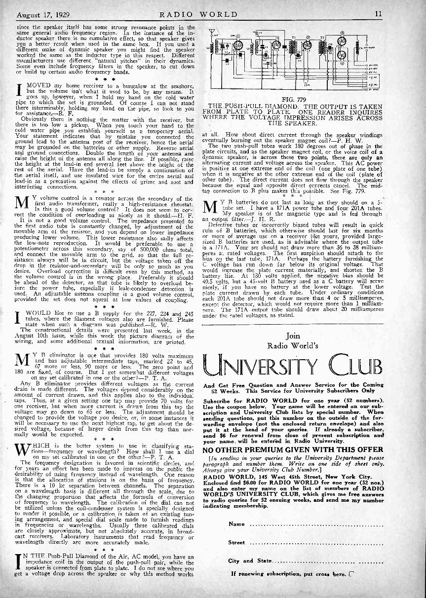
August 17, 1929 RADIO WORLD 11
since the speaker itself has some strong resonance points in thesame general audio frequency region. In the instance of the in-ductor speaker there is no cumulative effect, so that speaker givesyou a better result when used in the same box. If you used adifferent make of dynamic speaker you might find the speakerworked the same as the inductor type in this respect. Differentmanufacturers use different "natural pitches" in their dynamics.Some even include frequency filters in the speaker, to cut downor build up certain audio frequency bands.
* *IMOVED my home receiver to a bungalow at the seashore,
but the volume isn't what it used to be, by any means. Itgoes up, however, when I hold my hand on the cold water
pipe to which the set is grounded. Of course I can not standthere interminably, holding my hand on the pipe, so hook to youfor assistance.-R.. F.
Obviously there is nothing the matter with the receiver, butthere is too low a pickup. When you touch your hand to thecold water pipe you establish yourself as a temporary aerial.Your statement indicates that by mistake you connected theground lead to the antenna post of the receiver, hence the aerialmay be grounded on the batteries or other supply. Reverse aerialand ground connections. Double the length of your antenna andraise the height of the antenna all along the line. If possible, raisethe height at the lead-in end several feet above the height of therest of the aerial. Have the lead-in be simply a continuation ofthe aerial itself, and use insulated wire for the entire aerial andlead-in as a precaution against the effects of grime and soot andinterfering connections.
* * *
MY volume control is a resistor across the secondary of thefirst audio transformer, really a high -resistance rheostat.Is this a good volume control? It does not seem to cor-,
rect the condition of overloading as nicely as it should.-H. F.It is not a good volume control. The impedance presented to
the first audio tube is constantly changed, by adjustment of themovable arm of the resistor, and you depend on lower impedanceproducing lower volume. This lower resistance also sadly affectsthe low -note reproduction. It would be preferable to use apotentiometer across this secondary, say of 500,000 ohms total,and connect the movable arm to the grid, so that the full re-sistance always will be in circuit, but the voltage taken off thedrop in the resistor -and -secondary will be only so much as youdesire. Overload correction is difficult even by this method, asthe volume control is in the wrong place. Preferably it shouldbe ahead of the detector, as that tube is likely to overload be-fore the power tube, especially if leak -condenser detection isused. An adjustable antenna coupling is a good volume control,provided the set does not squeal at low values of coupling.
* * *IWOULD like to use a B supply for the 227, 224 and 245
tubes, where the filament voltages also are furnished. Pleasestate when such a diagram was published.-R. W.
The constructional details were presented last week, in theAugust 10th issue, while this week the picture diagram of thewiring, and some additional textual information, are printed.
* * *MY B eliminator is one that provides 180 volts maximum
and has adjustable intermediate taps, marked 22 to 45,67 more or less, 90 more or less. The zero point and
180 are fixed, of course. But I get somewhat different voltageson my set calibrated in one or the other ?-P. T. A.
Any B eliminator provides different voltages as the currentdrain is made different. The voltages depend considerably on theamount of current drawn, and this applies also to the individualtaps. Thus, at a given setting one tap may provide 70 volts forone receiver, but when more current is drawn from this tap thevoltage may go down to 65 or less. The adjustment should bechanged to provide the voltage you desire, or, in some instances itwill be necessary to use the next highest tap, to get about the de-sired voltage, because of larger drain from this tap than nor-mally would be expected.
* * *
WRICH is the better system to use in classifying sta-tions-frequency or wavelength? How shall I use a dialon my set calibrated in one or the other?-P. T. A.
The frequency designation is favored in scientific circles, andfor years an effort has been made to impress on the public thedesirability of using frequency instead of wavelength. One reasonis that the allocation of stations is on the basis of frequency.There is a 10 kc separation between channels. The separationon a wavelength basis is different all through the scale, due tothe changing proportion that affects the formula of conversionof frequency to wavelength. The calibration of the dial can notbe utilized unless the coil -condenser system is specially designedto render it possible, or a calibration is taken of an existing tun-ing arrangement, and special dial scale made to furnish readingsin frequencies or wavelengths. Usually these calibrated dialsare closely - approximate, but not absolutely accurate, in broad-cast receivers. Laboratory instruments that read frequency orwavelength directly are more accurately made.
* * *IN THE Push -Pull Diamond of the Air, AC model, you have an
impedance coil in the output of the push-pull pair, while thespeaker is connected from plate to plate. I do not see where you
get a voltage drop across the speaker or why this method works
FIG. 779THE PUSH-PULL DIAMOND. THE OUTPUT IS TAKEN
FROM PLATE TO PLATE. ONE READER INQUIRESWHERE THE VOLTAGE IMPRESSION ARISES ACROSS
THE SPEAKER.
at all. How about direct current through the speaker windingseventually burning out the speaker magnet coil?-P. H. W.
The two push-pull tubes work 180 degrees out of phase in theplate circuits, and as the speaker magnet coil, or the voice coil of adynamic speaker, is across these two points, there are only analternating current and voltage across the speaker. This AC poweris positive at one extreme end of the coil (one plate of one tube)when it is negative at the Other extreme end of the coil (plate ofother tube). The direct current does not flow through the speakerbecause the equal and opposite direct urrents cancel. The mid -tap connection to B plus makes this possible. See Fig. 779.
* * *
MY B batteries do not last as long as they should on a 5-tube set. I have a 171A power tube and four 201A tubes.My speaker is of the magnetic type and is fed through
an output filter.-J. H. R.Defective tubes or incorrectly biased tubes will result in quick
ruin of B batteries, which otherwise should last for six monthsor more of average use on a receiver like yours, provided large -sized B batteries are used, as is advisable where the output tubeis a 171A. Your set should not draw more than 36 to 38 milliam-peres at rated voltages. The first suspicion should attach to thebias on the last tube, 171A. Perhaps the battery furnishing theC voltage has run down far below its original voltage. Thatwould increase the plate current materially, and shorten the Bbattery life. At 180 volts applied, the negative bias should be40.5 volts, but a 45 -volt B battery used as a C battery will servenicely, if you have no battery at the lower voltage. Test theplate current drawn by each tube. Under ordinary conditionseach 201A tube should not draw more than 4 or 5 milliamperes,except the detector, which would not require more than 1 milliam-pere. The 171A output tube should draw about 20 milliamperesunder the rated voltages, as stated.
JoinRadio World's
NIVASIIFY CL BAnd Get Free Question and Answer Service for the Coming
52 Weeks. This Service for University Subscribers OnlySubscribe for RADIO WORLD for one year (52 numbers).Use the coupon below. Your name will be entered on our sub-scription and University Club lists by special number. Whensending questions, put this number on the outside of the for-warding envelope (not the enclosed return envelope) and alsoput it at the head of your queries. If already a subscriber,send $6 for renewal from close of present subscription andyour name, will be eifer-ea in Radio University.NO OTHER PREMIUM GIVEN WITH THIS OFFER
[In sending in your queries to the University Department pleaseparagraph and number them. Write on one side of sheet only.Always give your University Club Number.]RADIO WORLD, 145 West 45th Street, New York City.Enclosed find $6.00 for RADIO WORLD for one year (52 nos.)and also enter my name on the list of members of RADIOWORLD'S UNIVERSITY CLUB, which gives me free answersto radio queries for 52 ensuing weeks, and send me my numberindicating membership.
Name
Street
City and State
If renewing subscription, put cross here.
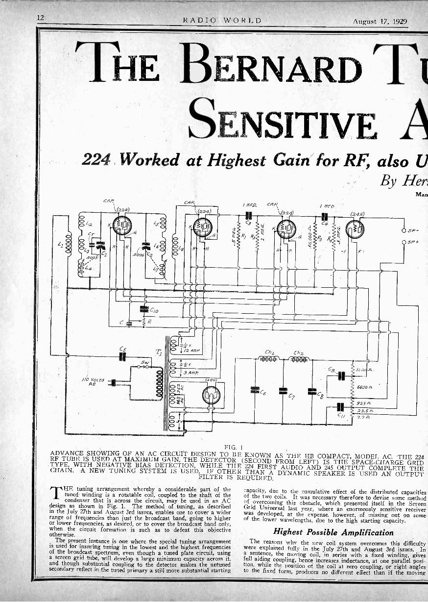
12 RADIO WORLD August 17, 1929
THE BERNARD TiSENSITIVE A
224 Worked at Highest Gain for RF, also UBy Her,
//O VOLT'SRC
CAP
O
2± Y./2 A M P
2± V.
3(.280)
GAF;
s,(224)
Ch2
00
0`)
/ MFO
itCg
3 4 L)
Man
(24s)
(t SP -
SP -f-
FIG. 1ADVANCE SHOWING OF AN AC CIRCUIT DESIGN TO B E KNOWN AS THE HB COMPACT, MODEL AC. THE 224RF TUBE IS USED AT MAXIMUM GAIN, THE DETECTOR (SECOND FROM LEFT) IS THE SPACE -CHARGE GRIDTYPE, WITH NEGATIVE BIAS DETECTION, WHILE THE 224 FIRST AUDIO AND 245 OUTPUT COMPLETE THECHAIN. A NEW TUNING SYSTEM IS USED. IF OTHER THAN A DYNAMIC SPEAKER IS USED AN OUTPUTFILTER IS REQUIRED.
THE tuning arrangement whereby a considerable part of thetuned winding is a rotatable coil, coupled to the shaft of thecondenser that is across the circuit, may be used in an AC
design as shown in Fig. 1. The method of tuning, as describedin the July 27th and August 3rd issues, enables one to cover a widerrange of frequencies than just the broadcast band, going to higheror lower frequencies, as desired, or to cover the broadcast band only,when the circuit formation is such as to defeat this objectiveotherwise.
The present instance is one where the special tuning arrangementis used for insuring tuning in the lowest and the highest frequenciesof the broadcast spectrum, even though a tuned plate circuit, usinga screen grid tube, will develop a large minimum capacity across it,and though substantial coupling to the detector makes the untunedsecondary reflect in the tuned primary a still more substantial starting
capacity, due to the cumulative effect of the distributed capacitiesof the two coils. It was necessary therefore to devise some methodof overcoming this obstacle, which presented itself in the ScreenGrid Universal last year, where an enormously sensitive receiverwas developed, at the expense, however, of missing out pn someof the lower wavelengths, due to the high starting capacity.
Highest Possible AmplificationThe reasons why the new coil system overcomes this difficulty
were explained fully in the July 27th and August 3rd issues. Ina sentence, the moving coil, in series with a fixed winding, givesfull aiding coupling, hence increases inductance, at one parallel posi-tion, while the position of the coil at zero coupling, or right anglesto the fixed form, produces no different effect than if the moving
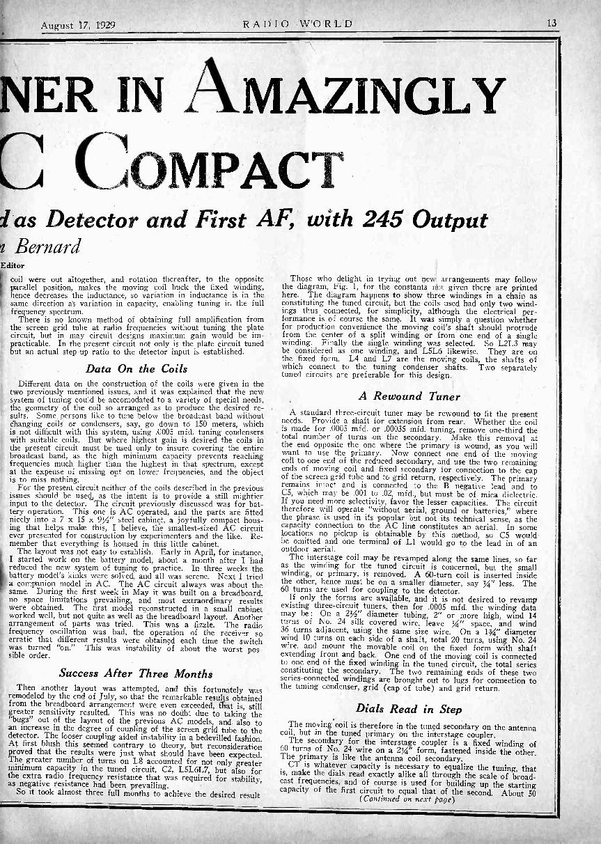
August 17, 1929 RADIO WORLD 13
NER IN AMAZINGLY
COMPACTal as Detector and First AF, with 245 Outputz BernardEditor
coil were out altogether, and rotation thereafter, to the oppositeparallel position, makes the moving coil buck the fixed winding,hence decreases the inductance, so variation in inductance is in thesame direction as variation in capacity, enabling tuning in the fullfrequency spectrum.
There is no known method of obtaining full amplification fromthe screen grid tube at radio frequencies without tuning the platecircuit, but in may circuit designs maximum gain would be im-practicable. In the present circuit not only is the plate circuit tunedbut an actual step-up ratio to the detector input is established.
Data On the CoilsDifferent data on the construction of the coils were given in the
two previously mentioned issues, and it was explained that the newsystem of tuning could be accomodated to a variety of special needs,the geometry of the coil so arranged as to produce the desired re-sults. Some, persons like to tune below the broadcast band withoutChanging coils or condensers, say, go down to 150 meters, whichis not difficult with this system, using .0005 mfd. tuning condenserswith suitable coils. But where highest gain is desired the coils inthe present circuit must be used only to insure covering the entirebroadcast band, as the high minimum capacity prevents reachingfrequencies much higher than the highest in that spectrum, exceptat the expense of missing out on lower frequencies, and the objectis to miss nothing.
For the present circuit neither of the coils described in the previousissues should be used,, as the intent is to provide a still mightierinput to the detector. The circuit previously discussed was for bat-tery operation. This one is AC operated, and the parts are fittednicely into a 7 x 15 x 9%" steel cabinet, a joyfully compact hous-ing that helps make this, I believe, the smallest -sized AC circuitever presented for construction by experimenters and the like. Re-member that everything is housed in this little cabinet.
The layout was not easy to establish. Early in April, for instance,I started work on the battery model, about a month after I hadreduced the new system of tuning to practice. In three weeks thebattery model's kinks were solved, and all was serene. Next I trieda companion model in AC. The AC circuit always was about thesame. During the first week in May it was built on a breadboard,no space limitations prevailing, and most extraordinary resultswere obtained. The first model reconstructed in a small cabinetworked well, but not quite as well as the breadboard layout. Anotherarrangement of parts was tried. This was a fizzle. The radiofrequency oscillation was bad, the operation of the receiver soerratic that different results were obtained each time the switchwas turned "on." This was instability of about the worst pos-sible order.
Success After Three MonthsThen another layout was attempted, and this fortunately was
remodeled by the end of July, so that the remarkable results obtainedfrom the breadboard arrangement were even exceeded, that is, stillgreater sensitivity resulted. This was no doubt due to taking the"bugs" out of the layout of the previous AC models, and also toan increase in the degree of coupling of the screen grid tube to thedetector. The looser coupling aided instability in a bedevilled fashion.At first blush this seemed contrary to theory, but reconsiderationproved that the results were just what should have been expected.The greater number of turns on L8 accounted for not only greaterminimum capacity in the tuned circuit, C2, L5L6L7, but also forthe extra radio frequency resistance that was required for stability,as negative resistance had been prevailing.
So it took almost three full months to achieve the desired result
Those who delight in trying out nevi arrangements may followthe diagram, Fig. 1, for the constants not, given there are printedhere. The diagram happens to show three windings in a chain asconstituting the tuned circuit, but the coils used had only two wind-ings thus connected, for simplicity, although the electrical per-formance is of course the same. It was simply a question whetherfor production convenience the moving coil's shaft should protrudefrom the center of a split winding or from one end of a singlewinding. Finally the single winding was selected. So L2L3 maybe considered as one winding, and L5L6 likewise. They are onthe fixed form. L4 and L7 are the moving coils, the shafts ofwhich connect to the tuning condenser shafts. Two separatelytuned circuits are preferable for this design.
A Rewound TunerA standard three -circuit tuner may be rewound to fit the present
needs. Provide a shaft for extension from rear. Whether the coilis made for .0005 mfd. or .00035 mid. tuning, remove one-third thetotal number of turns on the secondary. Make this removal atthe end opposite the one where the primary is wound, as you willwant to use the primary. Now connect one end of the movingcoil to one end of the reduced secondary, and use the two remainingends of moving coil and fixed secondary for connection to the capof the screen grid tube and to grid return, respectively. The primaryremains intact and is connected to the B negative lead and toC5, which may be .001 to .02, mfd., but must be of mica dielectric.If you need more selectivity, favor the lesser capacities. The circuittherefore will operate "without aerial, ground or batteries," wherethe phrase is used in its popular but not its technical sense, as thecapacity connection to the AC line constitutes an aerial. In somelocations no pickup is obtainable by this method, so C5 wouldbe omitted and one terminal of Ll would go to the lead in of anoutdoor aerial.
The interstage coil may be revamped along the same lines, so faras the winding for the tuned circuit is concerned, but the smallwinding, or primary, is removed. A 60 -turn coil is inserted insidethe other, hence must be on a smaller diameter, say IA" less. The60 turns are used for coupling to the detector.
If only the forms are available, and it is not desired to revampexisting three -circuit tuners, then for .0005 mfd. the winding datamay be: On a 2%" diameter tubing, 2" or more high, wind 14turns of No. 24 silk covered wire, leave Yt" space, and wind36 turns adjacent, using the same size wire. On a 1g." diameterwind 10 turns on each side of a shaft, total 20 turns, using No. 24wire, and mount the movable coil on the fixed form with shaftextending front and back. One end of the moving coil is connectedto one end of the fixed winding in the tuned circuit, the total seriesconstituting the secondary. The two remaining ends of these twoseries -connected windings are brought out to lugs for connection tothe tuning condenser, grid (cap of tube) and grid return.
Dials Read in StepThe moving coil is therefore in the tuned secondary on the antennacoil, but in the tuned primary on the interstage coupler.The secondary for the interstage coupler is a fixed winding of60 turns of No. 24 wire on a 2%." form, fastened inside the other.
The primary is like the antenna coil secondary.CT is whatever capacity is necessary to equalize the tuning, that
is, make the dials read exactly alike all through the scale of broad-cast frequencies, and of course is used for building up the startingcapacity of the first circuit to equal that of the second. About 50
(Continued on, next page)

14 RADIO WORLD August 17, 1929
NEW TUNERSShaft is Made Solid from Front to Back
TICKLER20 TURN
INSIDE FIXEDCOIL, 60 TURNS
TICKLER,20 TURNS
36 TURNS
gh II 0 0BT5B I1 / BT5A
SHAFTS EXTEND THROUGH
FIG. 2THE TWO COILS FOR THE HB COMPACT, THE SAMEINDUCTANCES TO BE USED FOR AC OR BATTERYMODEL. THE SHAFT HAS TO GO ALL THE WAYTHROUGH THE COIL FORM TO ENGAGE THE TUNINGCONDENSER SHAFT BY MEANS OF AN ADDITIONALFLEXIBLE COUPLING. THE NUMBER OF TURNS ISSTATED ON THE DIAGRAM. THE WIRE IS NO. 24SILK COVERED. THE DATA ARE FOR .0005 MFD.
TUNING.
(Continued from preceding page)mmfd. maximum has been found sufficient, the condenser being per-manently set at something less.
The coils may be mounted on the front panel, if condensers areused that do not have shafts projecting at their back, since thecoils provide the projecting piece. But if condensers with extensionshaft from rear are at hand, the condensers may be mounted onthe front panel, the coils behind them. Insulate the second condenserfrom a metal panel. In either instance an insulated flexible couplingis used.
In the final laboratory model the coils were mounted on the frontpanel, because the windings have no electrical connection with the
.moving form, whereas with a condenser the moving plates andthe shaft are one electrical lead. Hence though a metal cabinet, ofwhich the front panel is a part, was in the B minus lead, no shortresulted when the interstage coil was put on the front panel. Theabsence of electrical connection between coils and front panel, plusthe precaution of using an insulated flexible coupling device, pre-served the independence of the circuits, so that the tuned platecircuit, in the B plus lead, was not connected to the B minus lead,which would have shorted the B supply.
Constructional Details Soon
The discussion of the circuit shown in Fig. 1 is preliminary tothe publication of articles detailing the construction. These articlesare scheduled to be published in RADIO WORLD beginning in Sep-tember, but they will be preceded by constructional articles on thebattery model. For those who desire to experiment with the ACcircuit in advance of the details of just how it should be constructedthe following data are given: C is 1 mfd.; C10 is 4 mfd.; C6 andC7 are 2 mfd. each; C8 is 4 mfd. C9 is 2 mfd. The power trans-former block, with choke coils Chl and Ch2 built in, is the productof Polo Engineering Laboratories. The second is used as a spacecharge detector.
Some slight changes may be expected in the circuit formationwhen the constructional articles are published, although at presentno reason appears for making any changes. The reservation ismade, however, so that any who distinguish a difference betweenwhat is published in the present preliminary article, and what willappear later, will know that considerations of simplicity or per-formance have made it advisable to include the changes. It ispromised, however, that any alterations will be slight, so those whofeel like going ahead with a working model now will not have anytrouble including subsequent changes. At present they would haveto develop their own layout, and if all the parts are to be encom-
passed in the small space as previously stated, the builder will haveto resort to a little ingenuity.
Shaft In Three Pieces
The construction of the coils may have baffling features to someexperimenters, especially as the shaft has to run through thecoil to extend from the rear. The front part of the shaft isstandard and projects outward in the same manner and to the samedegree as any ordinary three -circuit tuner. The rear piece emergesonly V4. inch, however, because the longer this part is made, thegreater the distance of the tuning condenser from the coil, and thegreater the lost space. The shaft really consists of three pieces:first, the piece that pierces the coil form from the front, a screwat inside end; second, a connecting piece, tapped hole to fit thescrews; third, the piece that projects IA inch at rear, with screwat inside. As the necessary implements for providing screws atthe extreme pieces and for tapping tbe center piece may not be athand, it is suggested that any stiff shaft, of copper or brass, besoldered to the two extreme pieces to produce the unified result.This is a makeshift, but it will do nicely.
Look Out for the Roof
The best warning that can be given to any who attempt to followthe preliminary data and build up this receiver is to see that theroof is secure to the rest of the house, as the volume produced bythis circuit is far and away ahead of anything that you wouldexpect from a 4 -tube design. It is a 4 -tube set, not counting therectifier, but a custom is growing up of including the number ofrectifier tubes at the end, so this would be a 4-1 receiver, meaningfour AC tubes and one rectifier.
Some tests are being made now to determine if this is the bestfour -tube AC receiver, or 4-1 receiver, that has been developed sofar, considering of course the usual standards of sensitivity, selectiv-ity and tone, and as a fourth consideration including stability. Itis easy enough to obtain high sensitivity from a receiver consistingof few tubes if the set is made tediously critical, of the squealingtype, hard to control, but where decent stability is included, thenthe design of a sensitive and selective receiver consisting of fewtubes becomes more difficult.
So far nothing has proved itself superior to the present designfor AC operation, but the tests have not been completed, althougha fair and true report of the results, whatever they may be, willbe published.
Commercial Coils
The coils are now obtainable commercially, being known asBT5A for the antenna coil, and BT5B for the interstage coupler,both for .0005 mfd. The two coils of the commercial type, withwinding data, are illustrated on this page. They are manufacturedby the Screen Grid Coil Company. There are six terminals on thecoils, but interconnecting one tickler terminal and one terminal ofthe fixed secondary will reduce the externally connected outlet lugsto four for either coil: two for the primary and two for thesecondary. Remember that the 14 turns are the primary for an-tenna connection, while the tuned winding is the primary for theinterstage coupler.
[Other interesting data on the Bernard Tuner next week.]
A THOUGHT FOR THE WEEK
Through a love song we sit and we listenYou and I, in the twilight grey;
Never thought, dear, of lovin' or kissin'.Not a word, dear, have we to say.
Singer's voice, with emotion so laden,Clearly comes o'er my radio.
All is dark-but there's no use evadin'Gleamin' eyes of you, lady 0!
-R. B. H.

August 17, 1929 RADIO WORLD 15
EFFECTS OF GRIDSElectron Action in Tube Analyzed
By Harrington J. Forbes[What an electron is, how it behaves, and finally, what its impor-
tance is to the operation of a vacuum tube, were exposed last weekin the August 10th issue. An understanding of the electron theoryis highly important to a cultured appreciation of vacuum tube action.This week the electrons in the two-, three- and four -element tubesare discussed in the final instalment.-Editor.]
THE currents indicated by arrows in Fig. 3A are the elec- tron stream and not the conventional current, as isclearly indicated by the direction.
The scheme indicated in Fig. 3A is that of the diode, or two -element tubes first put to radio use by Fleming. It is used fordetection and for rectification, for example, in B supply units inwhich the rectifier tube isof the filament -type.
Insertion of GridNow let the arrangement in Fig. 3A be changed as shown in
(b). A grid G, consisting of parallel connected together metalli-cally, and indicated by circles, is interposed between A and K.The grid is kept negative with respect to K with the batteryEg, while the plate is kept positive with respect to the K withthe plate battery Eb.
Since G is negative with respect to K it will repel the elec-trons shot out from K, and it will therefore aid K in pullingthem back. The greater the negative charge, or potential, onG, the more effective G will be in repelling the electrons. SinceG is a grid in physical structure there are spaces where there isno repelling force and where electrons may get through if theycome up with sufficient velocity. The electrons are aided to getthrough the open spaces of the grid by the fact that the posi-tively charged plate acts through the openings, attracting theelectrons. Once an electron has passed through an opening inthe grid, they are not only attracted by the plate, but they arepushed in the same direction by the repulsion of the grid. Itis only those electrons which are projected from the cathodewith the highest velocities that are able to overcome the com-bined attraction of the cathode, the repulsion of those' electronsfarther away and the repulsion of the grid.
If G is maintained at a sufficiently high negative potential, fora given cathode temperature and a given plate potential, all theelectrons emitted are repelled so that none can get to the plate.This condition obtains when the negative grid voltage multipliedby the amplification factor of the tube is greater than the volt-age of the plate battery. Then there is no plate current.
Screen Grid AddedNow let a second grid be introduced into the tube, one sur-
rounding the plate as shown in Fig. 3C. In this drawing thecircles containing plus signs on the sides of the plate representthe cross sections of the screen grid wires. This grid is con-nected to a positive potential somewhat lower than that appliedto the plate. The portion Esg of the plate battery Eb is usedfor maintaining the screen grid positive with respect to thecathode.
The action of the cathode and the grid G is not changedmaterially by the introduction of the second grid, but the num-ber of electrons reaching the plate is different. Now both the
A
E
A
K a.ee
.0'e
. ee
. e
B
.: .
Eg
A
FIG. 3THE ELECTION CURRENTS IN THREE TYPES OF
TUBES. A REPRESENTS A DIODE, K BEING THE HOTEMITTER AND A THE PLATE OR ANODE. IN B THETRIODE IS REPRESENTED, IN C THE SCREEN GRIDTUBE OR TETRODE. THE ELECTION FLOW, NOT THE
REGULAR A AND B CURRENT FLOW, IS SHOWN.
plate and the screen grid attract electrons. They compete, soto speak, for the electrons that succeed in getting through thegrid openings. Suppose the screen grid voltage is fixed and theplate voltage varied from zero up to a value several timesgreater than the screen grid voltage.
Plate Begins to AttractWhen the plate voltage is zero the screen grid alone will
attract electrons and the plate current ip will be zero. Thescreen grid current is will be high, provided that the grid volt-age is not so much negative as to stop completely the electrons.As the plate voltage is increased the plate will begin to attractelectrons and plate current will flow. At the same time thenumber of electrons attracted to the screen grid will be reduced.When the screen grid and plate voltages are approximatelyequal the number of electrons attracted by the two electronswill also be equal. Then as the plate voltage is inreased abovethe value of the screen grid voltage, the number of electronsattracted to the screen grid will decrease continually and thoseattracted to the plate will increase. A plate saturation currentis soon reached as the voltage is increased, and this is deter-mined by the electron emission from the filament and on thenumber of electrons passed by the grid.
How to Operate TubeThe screen grid tube should be operated so that the effective
plate voltage is never less than about twice the value of thescreen grid voltage. When it is less the action of the tube isvery irregular.
Shielding Valuable But Exacts TaxThe eddy currents induced in any shielding, and which actually
do the shielding, require some energy, because no shieldingmaterial is a perfect conductor. This energy must come fromthe coil surrounded by the box, for there is no other source ofenergy. Any energy loss signifies resistance, and therefore theshielding introduces resistance into the coil and lowers the selec-tivity of the circuit of which it is a part.
The shielding has other detrimental effects. First it reducesthe effective inductance of the coil, for the inductance is themagnetic field per unit current, and the reflected field opposesthe original field. Thus when shielding is used more wire mustbe used to obtain a given inductance. The added wire addsmore 'resistance.
However, there is an effect which offsets this effect, and that
is the capacity between the shield and the components of thetuned circuit. This added capacity is quite considerable if theshield material is close to the coil. The distributed capacity thusadded decreases the tuning range of a given coil and condenser.In order ,to cover the broadcast band with a single coil andcondenser it may be necessary to make the range of the con-denser 0-750 mmfd. instead of 0-500 mmfd.
Shielding is not necessary in all instances, only when thereare three or more tuned stages with a high degree of amplifica-tion in each. When there are only two tuned circuits, even whenone or two screen grid tubes are used, shielding as a rule doesmore .harm than good. It may stop oscillation, but at a highcost of sensitivity and selectivity. There are other methods ofsecuring stability in simple circuits.
16 RADIO WORLD August 17, 1929
STATIONS KEEP
AIR CLEAR Of
STOCK GAMBLEWhile the New York Stock Exchange
has established rules to govern broad-casting of stock quotations and other fin-ancial information by its members, NewYork radio stations do not manifest muchinterest in such broadcasts.
John Gordon, sales manager for theColumbia Broadcasting System, said thatseveral brokerage firms had made requeststo broadcast stock reports and advice, butthat all requests had been rejected.
"We have always fought shy of anybroadcasting of a speculative nature," hesaid, "and when such propositions were sub-mitted they were immediately rejected."
No requests by financial concerns for thebroadcasting of stock quotations have beenmade to the National Broadcasting Com-pany, a representative of that company said,and if any request is made, it will be ac-cepted only on the same basis as the stockbroadcasts by WJZ daily, which informa-tion is now supplied by the AssociatedPress.
A year ago WMCA settled the questionof stock quotations sponsored by a broker-age firm by deciding in the negative, accord-ing to a representative of that station.
"Radio Questions"in a New Edition
Radio Operating Questions and Answers, byArthur R. Nilson and J. L. Hornung. McGraw..Hill Book Company, Inc., New York ($2.00).
This is the second edition of the author'sbook, "Radio Questions and Answers,"brought up to date to meet the many changesin the art of radio communication since thepublication of the first edition in 1921.
The book is primarily intended for thosestudents of radio preparing to take theUnited States Government examination forcommercial operating licenses, and, as thetitle indicates, the treatment is in the formof questions and answers. There are 399questions in the book, with complete answers,covering every subject necessary for under-standing the operation of commercial andbroadcast radio stations. There are also twoappendices covering Government regulationsand international abbreviations and conven-tions. The book is well indexed for readyreference.
Station in BuffaloWould Fight Monopoly
Washington.The Buffalo "Evening News" filed with
the Federal Radio Commission an applica-tion for authority to construct and operatea broadcasting station in Buffalo, N. Y.The channel of 900 kilocycles is requestedfor full time operation and with 1,000 wattspower.
Reasons for the request are stated asfollows
"Since the four leading radio stationsin Buffalo have come under the controland management of the Buffalo Broad-casting Corporation, service to the publicgradually has deteriorated. Programs arebeing interrupted with all kinds of directadvertising announcements. The presentlocal monopoly is not in the public interest.The effective competition and high-graderadio service, which will be insured if thisapplication is granted, will restore to thepublic its rights in radio."
ForumJust What He Wanted
IT'S great to read how to build an ABCsupply for 224, 227 and 245 tubes, in-cluding push-pull, if you like. The ar-
ticle in the August 10th issue was just thething, especially as the resistance valueswere given clearly, and the AC secondaryhigh voltage and equivalent DC resultswere stated and explained. I shoppedaround for a commercial outfit of this kindbut found none, so will build the ABC com-pact. Good luck to you and thanks.
Howard Brush, Miami, Fla.* * *
Not One TumbleIHAD my name in the Literature Wanted
column, with a keyed address, but no-body sent me any literature. Is not
this column a waste of space?Jonah Fallerton, Tulsa, Okla.
* * *
He Has Tubes in MindUBES and how to use them constituteTthe most interesting subject in radio.Publish more and more and mdre
about tubes, tubes, tubes. Characteristiccurves, load requirements, mus, voltages,currents, power. Please, please, please
Emil Bass, Detroit, Mich.
MICROPHONES
ARE EXACTINGA. J. McCosker, director of WOR,
Newark, N. J., said:"One of the mysteries of radio is why
the microphone accentuates the faults ofsome artists and builds up the excellence ofothers. I have heard singers 'knock 'emdead' who obviously should have been board -casters instead of broadcasters. On theother hand, a tenor who had been selectedover eighty competitors, because of his ex-cellent voice, as the juvenile lead in anoperetta, proved an unqualified 'flop.' Andthis was in spite of his years of study andtraining.
"Technicians are unable to explain it. J.R. Poppele, WOR's chief engineer, likensthe mystery to that of the camera. 'Whyis it,' he asks, `that the camera will flatterone person and damn another ? Photogra-phers have a lot of theories for such phe-nomena, but nothing tangible.'
"It is the same with the microphone. Itplays many tricks on radio entertainers, butlike the practical joker, will stand for noneon itself. One cannot convince the victimsof the camera and microphone that they donot lie.
"Science has learned a lot about voicefrequencies Wand all other vibrations. Weknow that all material responds to a naturalfrequency. It may be that the artist whobroadcasts well vibrates at the same ornearly the same as the microphone itself.At any rate, it furnishes an interestingbasis for speculation.
"The condenser microphone has elimi-nated much of the trouble, although I amstill convinced that the study of micro-phonology is only beginning."
WINR LICENSE EXTENDEDWashington.
The radio license of WINR of Bay Shore,L. I., has been extended until Oct. 31. Thestation's status is being investigated by thelegal division of the Radio Commission.
WEST RECEIVES
BETTER, BOARD
MEMBER FINDSBy Harold A. La fount
FEDERAL RADIO COMMISSIONERThe sale of radio receiving sets has
been much larger during the Summer thanhad been anticipated. Indications are thatduring the Fall and Winter months *herewill be a very substantial increase in thesale of receiving sets over last year.
There is plenty of talent in Los Angeles,San Francisco, Seattle, and Denver. Thesecities are drawing from the Middle and}"ar West, and to some extent from theEast, with the result that the available sup-ply of artists has increased 40 per cent ina year. California's climate is partly re-sponsible for the assembling of artists inthat State.
The West is highly appreciative of thewonderful programs broadcast by the twoEastern chain broadcasting companies.These programs, originating in New YorkCity, are extremely popular and thorough-ly enjoyed. The Western chain stationsare also presenting programs of unusualmerit. Little or no complaint is made aboutduplication of programs.
Reception Materially BetterReception was without doubt improved
materially by the November 11th alloca-tion. There are, however, still some roughspots which I hope can be ironed out soon.
Everywhere I found the radio super-visors, under the Department of Commerce,working in perfect harmony with all broad-casters and others interested in radio. Theyare doing a wonderful work and too muchcredit cannot be given to them. -It is, how-ever, unfortunate that they are without suf-ficient help, room and equipment.
Radio dealers are well organized in allWestern States and are doing some realconstructive work. The radio broadcastersare also forming local organizations andmany are joining the national organization.They are adopting a code of ethics anddignifying the profession a great deal, allof which is without doubt in the publicinterest.
Reports on Listeners' ClubsListeners' clubs are organized in many
Western cities and are doing some goodwork and furnishing valuable information.In Butte, Mont., the club has 2,000 activemembers, who employ a trouble man tocheck upon all local interferences, remedy-ing them wherever possible.
Some cities and States are passing, orhave already on record, laws and ordi-nances against local radio interferences.
In general I am delighted with the re-sults of my trip.
There is a great improvement in West-ern programs. Certainly there are yet sta-tions which rely too much on phonographrecords and there is still too much ad-vertising and talk over some stations, but,generally speaking, programs are much bet-ter than they were a year ago. Tore edu-cational features and better music are di-rectly responsible for the improvement.
NO USETheatrical managers, who only a year or
so ago, would have nothing to do withradio, are linked up so closely with broad-casting that it forms one of their greatestactivities. Their thought seems to be :"What's the use of swimming againft thetide?" The R. C. A. has answered thequery.

August 17, 1929 RADIO WORLD 17
WDAF SEEKING
FULL TIME AND
10 KILOWATTSWashington.
Seven stations have made applicationto the Federal Radio Commission for per-mission to make changes, includingpower and time.
KID, Jack Duckworth, Idaho Falls,Idaho, requests authority to reconstructstation and also requests an increase inassigned power from 250 watts day andnight to 500 watts day and 250 wattsnight.
KGDM, E. F. Peffer, Stockton,. Cali-fornia, requests authority to install newequipment, an increase in power from 50watts to 500 watts, and increase in hoursof operation.
WHN Asks 5,000 Watts
WDAF, at Kansas City, Mo., operatedby the "Kansas City Star," asks permis-sion to increase from 1,000 to 10,000
watts. The station recently applied forfull-time operation.
WSSH, Boston, Mass., asks an increasein power from 100 watts day 250 wattsnight to 500 watts power day and nightand also requests a change of frequencyfrom 1,420 to 1,360 kilocycles.
WHN, Marcus Loew Booking Agency,Inc., New York, requests permission toinstall new equipment, increase in powerfrom 250 watts to 5 kilowatts, change
from 1,010 to 1,100 kilo-cycles, and more hours of operation.
Application for WISN
WNYC, operated by the City of NewYork, requests a license to cover con-struction permit issued for reconstructionof station only.
WISN, Evening Wisconsin Company,Milwaukee, Wis., requests an increase inpower from 250 to 500 watts, a changein frequency from 1,120 to 940 kilocycles,and full time from dividing with stationWHAD.
REPLOGLE APPOINTEDThe National Carbon Company appointed
Delbert E. Replogle as sales engineer in, theProduct Development, Division. Mr. Rep-logle left the Raytheon Manufacturing Com-pany, the control of production and sales ofwhose products recently was acquired bythe National Carbon Company.
NEW CORPORATIONSMotor Matic Radio Appliances, radio-Atty. I.
Golembe, 17 John St., New York, N. Y.American Acoustic Co., Wilmington, Del.,
patents-Corporation Service Co.Peekskill Radiophone Corp., Peekskill-Atty H.
Civilett, 27 William St., New York, N. Y.Raffer's Radio Service-Atty. S. Cohn, 50 Court
St., Brooklyn, N. Y.H. A. Roth, radio stores-Atty. H. Schwartz, 26
Court St., BrooklynHub Radio Co.-Attv. S. Rothenberg, 353 Stone
Ave., Brooklyn, N. Y.Rent -A -Radio, radios-Attys. Joseph & Demov,
1431 Broadway, New YorkBeverly Radio Laboratories-Atty. F. C. How-
ard! Buffalo. N. Y.Silber's Radio Stores-Atty. A. Bauman, 26
Court St., Brooklyn, N. Y.Trutone Radio Products, Buffalo-Atty. P. Cata-
lano, Buffalo, N. Y.Federal Radio Broadcasting Corp., elevision ex-
periments-Delaware Registration Trust Co.International Talking Pictures, Inc., Dover, Del.
-Arley B. Magee, Inc. Dover, Del.Black Radio Corn.-Attys. Kohn & Goldman, 120
Broadway, New YorkSouth Jersey Radio and Electric Co., Riverton,
N. I.Universal Coin Radio Co., Inc., Wilmington,
Del. radio sets-Delaware Registration Trust Co.
Literature WantedTHE names and addresses of readers of
RADIO WORLD who desire literatureon parts and sets from radio manufae-
ttsrerso jobbqrs, dealers and mail orderhouses are published in RADIO WORLDon request of the reader. The blank atbottom may be used, or a post card or let-ter will do instead.
RADIO WORLD,145 West 45th St., N. Y. l ity.
I desire to receive radio literature.
Name
Address
City or town
State
Win Benert, Apt. 6L, 8716 Ridge Blvd., Brook-lyn, N. Y.
H. R. Elvey, 295 First Ave., Manasquan, N. J.Edward Hooker, 1040 Park Ave., New York, N. Y.Win. L. Vogel, 4 Clarendon St., Roslindale, Mass.Albert J. Santoro, 203 Tillary St., Brooklyn, N. Y.Richard E. Rose, P. 0. Box 93, Gilroy, Calif.F. A. Wallace, R. No. 3, Box 060, Auburn, Wash.Joseph C. Roney, 1402 W. 3rd St., Grand Island,
Nebr.F. Mohlar, 1653 Broadway, Brooklyn, N. Y.John Leitham, Jr., 180 E. Kilbourn, Milwaukee,
Wis.Eugene F. Badger, 2723 N. La Salle, Indianapo-
lis, Ind.E. T. Gan, 5739 Drexel Ave., Chicago, Ill.W. R. Cameron, 4245 Saline St., Pittsburgh, Pa.Roy G. Wild, Big Pine, N. C.Wright Ellis, 902 E. Adams, R. No. 6, Pitts-
burg, Kansas.E. Lee, Box 501, Florence, S. C.Ernest Mayo, 1409 Jefferson St., New Berry, S. C.R. H. Mitchell, 210 34th St., Newport News, Va.Robt. L. Margeson, Berwick, Nova Scotia.S. K. Hale, 10 Sussex Apartment, Portsmouth,
Va.S. V. Boone, 204 N. Sycamore St., Charlotte, N. C.H. N. Stone, 1% Howard St., Framingham, Mass.H. L. Adams, 208 Barclay St., Astoria, L. I.,
N. Y.John T. Gerber, 131 Vine St., East Providence,
R. I.Wm. Ebling, 431 Fairview Ave., Turtle Creek,
Pa.L. T. DeaTelhauser, State Sanatorium, Maryland.
L. Newton, 4th and Wall Sts., Joplin, Mo.Chas. Vogel. 566 Eagle Ave., Bronx, N. Y. City.G. A. Thurling, Humber Bay, Ont., Can.Wm. W. Groom, Addison, Mich.H. Burke, 3 Wykagyl Terrace New Rochelle,
N. Y.Anthony J. Truskey, 3942 Pulaski Ave., Phila,
Pa.Floyd Cox. Jr., Box 1005, Dalhart, Texas.Cecil W. McComas, 12421/ Charleston St., Charles-
ton, W. Va.A. C. Hall, 20 Cardinal Ave., St. I.uarent, Que.,
Can.Mirl H. Simmons, 122 Main Street, Ronceverte,
W. Va.Fred A. Schaerf, 328 McKinley Ave., San Anto-
nio, Tex.John A. Larson, 422 Brook Ave., Bronx, N. Y.
City.Carl E. Schneider, 1255 Shelby St., Indianapolis,
Ind.
SUMMER SALES
CALLED LARGEA survey of the radio industry, according
to H. B. Richmond, president of the RadioManufacturers' Association, indicates ' an-other excellent radio year. Summer sales,President Richmond states, are in unusualvolume, although the present season lacksthe stimulus of the Presidential electioncampaign enjoyed last year.
"The actual number of receiving sets soldthis year may not equal last year's recordtotal;" said Richmond, "but, 'all in all, thisseason shapes up as an excellent one. Busi-ness in accessories, such as tubes, is greatlyincreased, and during the 1929-30 seasonprobably will smash all previous records.
"Whether the total volume of radio saleswill change materially over last year is ques-tionable, as the average price of receivingsets will be lower, with a decrease in unitcost, despite an increase in performance andvalue given to the public per dollar."
Richmond is an engineer, the first engineerto head the national organization of radiomanufacturers.
PROFESSIONALS
ONLY, THE RULE
FOR AIR ACTORSThe employment of professional actors
and actresses by the larger broadcasting sta-tions, particularly those stations from ,which,chain programs emanate, is fast becoming,the inflexible rule, owing to the higher qual-ity of programs, prevailing. The change isexpected to be' complete when the new sea-son starts in September, marking the fulltransition of radio artistic work from theamateur to the professional class.
The stations' that try to get free talent,including getting professionals to whom thelure of "publicity" is offered, are having aharder time succeeding, not only becauselarge opportfinities exist to obtain payingemployment but also because some of theprofessional alliances have enacted rules pro-hibiting their members from making freeappearances. -
Stations Follow Suit
High-class programs by advertisers arelargely responsible for the confinement ofemployment to professionals, as the adver-tisers say they are not interested in indiffer-ent performances. But the large stationsthemselves employ professional talent regu-larly for "sustaining" programs, these beingpaid for entirely by the stations, and dis-tinguished from programs paid for by ad-vertisers, which are called "sponsored" pro-grams, even though the money received fortime on the air is the more sustaining.
In dramatic performances only profes-sionals are desired, and the National Broad-casting Company, which maintains a dra-matic department, called Radio Guild, nowhaving from 25 to 50 professionals, depend-ing on the demand, is expected soon to in-crease the number to 150, and to hold it atthis figure during the height of the season.
Pay the Actors Get
Leading actors and 'actresses are said toreceive $50 to $100 for a performance, andsome of ' them are booked for two or threeperformances a week. Several are said toaverage from $150 to $200 a week.
Decline in the opportunities offered by the"legitimate" stage, meaning dramatic andcomedy performances, with or withoutmusic, as distinguished from vaudeville, hasmade quite a dent in this branch of the actingprofession. The talkies provided an oppor-tunity, but not for everyone, owing to therequirement of good looks, so radio presentsan opportunity that is expected to last untilteletvision institutes the "good -looks" re-quirement in radio also. Most of the radioperformers, however, are not hard to look at.
Big New FactoryTo Make E -R Tubes
With most of the machinery installed inits new plant at Newton, Mass., the Ray-theon Manufacturing Company is rapidlypreparing to meet the demands of increasedproduction put upon it by its recently rati-fied agreement under which the NationalCarbon Company assumes control of Ray-theon's manufacture and distribution.
The new factory is three and one-halftimes as large as the former plant at Cam-bridge and will provide facilities for in-creasing the production of Eveready-Ray-theon tubes five -fold.

18 RADIO WORLD August 17, 1929
Aluminum SubpanelThe best appearance of the New Diamond of theAir results from using the official aluminum sub -panel, 10 x20 inches, witlh the four sockets builtin, and with self -bracketing front. Hardware andinsulating washers supplied with each sub -panel.The aluminum sub -panel is exactly the same asthe one used in the laboratory models of thebattery operated and the AC Screen Grid Dia-monds. Holes are drilled for mounting parts, butas this aluminum drills like bakelite you candrill any holes you want.
RADIO WORLD, 14.5 W. 45th St., N. Y. City.(lust East of Broadway)
Enclosed please Ind $3.00 for which please sendone aluminum subpanel 10x20" for the new batterymodel 4 tube SO Diamond of the Air, with socketsbuilt in, and with self -bracketing front and side andrear supports; also send hardware and insulatingwashers
O Enclosed please Ind $2.35 for which please send7x21" drilled Bakelite front panel for the new bat-tery model Diamond.o Enclosed please find $3.25 for the 10x20" aluminumsubpanel, etc., for the new AC Screen Grid Diamond.o Enclosed please find $2.35 for the 7x21" drilledBakelite front panel for the new AC Screen GridDiamond.
ID Enclosed please find $5.00 for both the aluminumII subpanel, etc., and the drilled Bakelite front panel
of the battery model.o Enclosed please find $5.25 for both the aluminumsubpanel, etc., and the drilled Bakelite front paso1of the AC model.
1 Name
Address
City State
FREE!
Send $6for year'sRadio WorldSubscriptionAnd ObtainUnit FREE!Radio World for one year(52 numbers, one each week)will keep you abreast oflatest circuits and news.Act now. Offer revocablewithout notice.0 If renewal put cross here.Radio World, 145 West 45th St.,
N. Y. City.Enclosed please find $6 for oneyear's subscription for RadioWorld (52 numbers). Send your"superb unit" free.
Single Copy $ .15Three Months 1.50Six Months 3.00One Year. 52 Issues 6.00
Add $1.00 a Year for ForeignPostage; 50c for Canadian Postage.
ARISTOCRATNew Diamond FLOOR SPEAKER
PARTS FOR BATTERY MODEL DIAMOND
C1-Aerovox .0005 moulded fixed .25C2-Hammarlund .0005 mfd. Midline 5.30C3, C4 -Two Aerovox moulded .006 mfd. @ .50 ea 1.00C5-Hammarlund .0005 mfd. Midline 5.30C6-Aerovox .00025 moulded fixed with clips .90CI-Aerovox .0005 moulded fixed .25A1-622 Amperite with mount .85AS, A3, A4 -Three IA Amperites, three mounts
@ .85 _ 2.55RI -50 -ohm Frost rheostat 1.00112-5-meg. Lynch metallized leak .40T1, 12 -Two National A100 audios @ $5.70 ea- . 11.40Ant., God., Sp. -, Sp. + posts @ .10 ea .40Pl-Yaxley jewel window bracket .35 with pilot lamp
.20 .55Sw-Yaxlei No. 10 A battery switch .357 1 21 -inch front panel 2.5510 x 20 -inch offleial battery Diamond subpanel, self -
bracketing, with four sockets affixed; subpanelhardware, insulated bushings, washers 3.00
Front panel and subpanel together 5.00Two dials with pointers 2.00Two knobs @ .20 .40One roll stranded Braidite .90Hammarlund 70 mmfd. Equalizer .40Four Kelly tubes: one 222, two 201A, one 112A or
171A 7.00
GUARANTY RADIO GOODS CO.143 WEST 45th STREET(Just East of Broadway)
NEW YORK CITY
11111111111111111111111111111111111111111111101111111111111111111111111111111111111
AERIAL TUNERImproves Summer Reception
..7m,pvp01" 11%
4f.,1(L)
Remove aerial lead from set. Connect aerialinstead to one of the binding posts of the AerialTuner. Connect the other binding post of theAerial Tuner to antenna post of your set. Thenmove the lever of the Aerial Tuner until any weakstation comes in loudest. The lever need not bemoved for every different frequency tuned in.The Aerial Tuner acts as an antenna loadingcoil and puts the antenna's frequency at anyfrequency in the broadcast band that you desireto build up. It makes high wavelengths come inloud as low wavelengths. It helps separate sta-tions and clear up reception. Makes great im-provement in Summer reception. Price, $1.00.
GUARANTY RADIO GOODS CO.143 West 45th Street
New York City
(Just East of Broadway)
0141000%/%11%"0111%.
With Molded Wood Horn of 6 ft.tone travel (exponential type) withbaffle and horn motor built Is.Extraordinary born I a.
the speaker cabinet is walnut finish, 33" high,/41/2" wide,. 17%". deep,. with. carved, legs.Golden cloth grille covers front opening. .Builtinside is No. 595 molded wood horn with baffleand No. 203 driving motor unit that stands HOvolts without filtration. Horn and motor re-movable. Table alone is worth price asked.Remit with order and we pay cartage on Aristo-crat Floor Speaker.
Acoustical Engineering Associates143 WEST 45th STREET
NEW YORK CITY(Just East of Broadway)
NEP
All Parts for
PUSH-PULL DIAMONDMershon Electrolytic
Condensers, four in oneCopper Container
8-8-18-18 mad.List price, $9.60
10-10-10-10 mfd.List price, $7.75
$5.76Net
$4.65Net
Filament Transformer, 2%, 5, 2% v ,net WOOPower Transformer, 2%, 5, 2%, 300,
300 v., net 10.00S M Unichoke 331, net 4.811
Guaranty Radio Goods Co.143 West 45th Street
New York City(Just East of Broadway)
FILL OUT AND MAIL NOWSUBSCRIPTION BLANK
RADIO WORLDRADIO WORLD 145 West 45th Street, New York City
(Just East of Broadway)Please send me RADIO WORLD for
SUBSCRIPTION RATES: please find enclosed
months, for which
Name
Address
City State
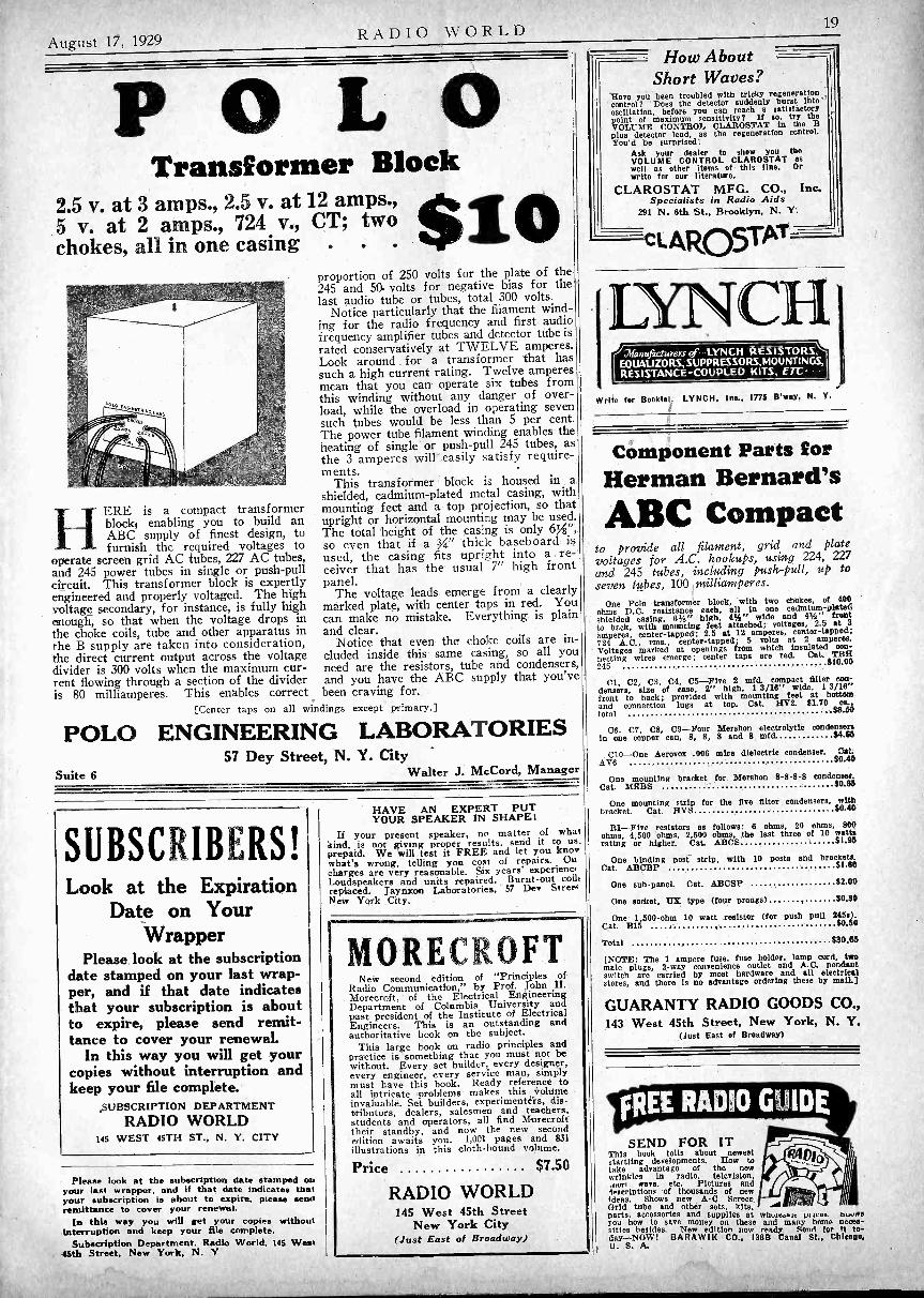
August 17, 1929 RADIO WORLD 19
POLOTransformer Block
2.5 v. at 3 amps., 2.5 v. at 12 amps.,5 v. at 2 amps., 724 v., CT; twochokes, all in one casing .
HERE is a compact transformerblock; enabling you to build anABC supply of finest design, tofurnish the required voltages to
operate screen grid AC tubes, 227 AC tubes,and 245 power tubes in single or push-pullcircuit. This transformer block is expertlyengineered and properly voltaged. The highvoltage secondary, for instance, is fully highenough, so that when the voltage drops inthe choke coils, tube and other apparatus inthe B supply are taken into consideration,the direct current output across the voltagedivider is 300 volts when the maximum cur-rent flowing through a section of the divideris 80 milliamperes. This enables correct
proportion of 250 volts for the plate of the245 and 50. volts for negative bias for thelast audio tube or tubes, total 300 volts.
Notice particularly that the filament wind-ing for the radio frequency and first audiofrequency amplifier tubes and detector tube israted conservatively at TWELVE amperes.Look around for a transformer that hassuch a high current rating. Twelve amperesmean that you can operate six tubes fromthis winding without any danger of over-load, while the overload in operating sevensuch tubes would be less than 5 per cent.The power tube filament winding enables theheating of single or push-pull 245 tubes, asthe 3 amperes will easily satisfy require-ments.
This transformer block is housed in ashielded, cadmium -plated metal casing, withmounting feet and a top projection, so thatupright or horizontal mounting may be used.The total height of the casing is only 6%",so even that if a 3/4" thick baseboard isused, the casing fits upright into a re-ceiver that has the usual 7" high frontpanel.
The voltage leads emerge from a clearlymarked plate, with center taps in red. Youcan make no mistake. Everything is plainand clear.
Notice that even the choke coils are in-cluded inside this same casing, so all youneed are the resistors, tube and condensers,and you have the ABC supply that you'vebeen craving for.
[Center taps on all windings except primary.]
POLO ENGINEERING LABORATORIES57 Dey Street, N. Y. City -
Suite 6 Walter J. McCord, Manager
SUBSCRIBERS!Look at the Expiration
Date on YourWrapper
Please look at the subscriptiondate stamped on your last wrap-per, and if that date indicatesthat your subscription is aboutto expire, please send remit-tance to cover your renewal.
In this way you will get yourcopies without interruption andkeep your file complete.
SUBSCRIPTION DEPARTMENTRADIO WORLD
145 WEST 45TH ST., N. Y. CITY
Please look at the subscription date stamped onyour last wrapper, and if that date indicates thatyour subscription is about to expire, please sendremittance to cover your renewal.
In this way you will get your copies withoutinterruption and keep your file complete.
Subscription Department. Radio World, 145 West45th Street, New York, N. Y
HAVE AN EXPERT PUTYOUR SPEAKER IN SHAPE!
If your present speaker, no matter of whatkind, is not giving proper results, send it to us.prepaid. We will test it FREE and let you knowwhat's wrong, telling you cost of repairs. Oucharges are very reasonable. Six years' experienc,Loudspeakers and units repaired. Burnt -out coil,replaced. Jaynxon Laboratories, 57 Dev StreetNew York City.
MORECROFTNew second edition of "Principles of
Radio Communication," by Prof. John H.Morecroft, of the Electrical EngineeringDepartment of Columbia University andpast president of the Institute of ElectricalEngineers. This is an outstanding andauthoritative book on the subject.
This large book on radio principles andpractice is something that you must not bewithout. Every set builder, every designer,every engineer, every service man, simplymust have this book. Ready reference toall intricate problems makes this Volumeinvaluable. Set builders, experimenters, dis-tributors, dealers, salesmen and teachers.students and operators, all find Morecrofttheir standby, and now the new secondedition awaits you. 1,001 pages and 831illustrations in this cloth -bound volume.
Price $7.50
RADIO WORLD145 West 45th Street
New York City(Just East of Broadway)
Write for Booklet. LYNCH, Inc., 1775 B'way, N.
How AboutShort Waves?
Have you been troubled with tricky regenerationcontrol? Does the detector suddenly burst into"oscillation, before you can reach a satisfactorypoint of maximum sensitivity? If so, try theVOLUME CONTROL CLAROSTAT in the Bplus detector lead, as the regeneration control.You'd be surprised!
Ask your dealer to show you theVOLUME CONTROL CLAROSTAT aswell as other items of this line. Orwrite for our literature.
CLAROSTAT MFG. CO., Inc.Specialists in Radio Aids
291 N. 6th St., Brooklyn, N. Y'.
cLAROSTAT
Manufacturers LYNCH RESISTORS,EODAUZORS,SUPPRESSORS,MOUNTINGS,RESISTANCE -COUPLED KITS, ETC
CH 1
Y.
Component Parts forHerman Bernard'sABC Compact
to provide all filament, grid and platevoltages for A.C. hookups, using 224, 227and 245 tubes, including push-pull, up toseven tubes, 100 milliamperes.
One Polo transformer block, with two chokes, of 400ohms D.C. resistance each, all In one cadmium -Pittedshielded casing, 63/4" high, 41/2" wide and 41/2" frontto bock, with mounting feet attached; voltages, 2.5 atamperes, center -tapped; 2.5 at 12 amperes, center -tapped;724 A.C., rms., center -tapped; 5 volts at 2 amperes.Voltages marked at openings from which insulated con-necting wires emerge; center taps are red. Cat TRH245 $10.00
CI, C2, C3, C4, C5-Five 2 mfd. compact filter con-densers, size of case, 2" high, 1 3/16" wide, 1 3/16"front to back; provided with mounting feet at bottom
and] 88.50connection lugs at top. Cat. HV2. $1.70 ea.,tot
C6, C7, C8, C9-Four Mershon electrolytic condensersin one copper can, 8, 8, 8 and 8 mfd. $4.65
C10-One Aerovox .006 mica dielectric condenser. Cat.AV6 $0.40
One mounting bracket for Mershon 8-8-8-8 condenser.Cat. MEBS $0.35
One mounting strip for the five filter condensers, withbracket. Cat. HVS $0.40
R1-Five resistors as follows: 6 ohms, 20 ohms, 800ohms, 4,500 ohms, 2,500 ohms, the last three of 10 wattsrating or higher. Cat. ABCS $1.95
One binding post strip, with 10 posts and brackets.Cat. ABCBP $1.60
One sub-paneL Cat. ABCSP $2.00
One socket, IT% type (four prongs) $0.30
One 1,500 -ohm 10 watt resistor (for push pull 245s).Cat. B15 $0.50
Total $30.65
[NOTE: The 1 ampere fuse, fuse holder, lamp cord, twomale plugs, 2 -way convenience outlet and A.C. pendantswitch are carried by most hardware and all electricalstores, and there is no advantage ordering these by mail]
GUARANTY RADIO GOODS CO.,143 West 45th Street, New York, N. Y.
(Just East of Broadway)
SEND FOR ITThis book tells about neweststartling developments. How totake advantage of the newwrinkles in radio, television,.fityrt ware. etc. Pictures andlescriptions of thousands of newideas. Shows new A -C ScreenGrid tube and other sets, kits. -41parts, accessories and supplies at whuie.ai, pe Aces. mowsyou how to save money on these and many home neces-sities besides. New edition now reacts,. Send for It to-day-NOWT BARAWIK CO., 138B Canal St., ChInt0a,U. S. A.

20 RADIO WORLD August 17, 1929
New Junior Model
POLO UNIT $4
The famous twin magnet principle fordouble sensitivity, large magnets for greatflux, permanently adjusted armature, allare in the new junior model Polo Unit.Weight, 2,/4 lbs. Stands 150 volts unfil-tered. Stands up to 250 push-pull filtered.Works any output tube, power or other-wise. Supplied with 10 -ft. cord. Orderunit now. Five-day money -back guarantee.
Acoustical EngineeringAssociates
143 West 45th StreetNew York City
(Just East of Broadway)vowasial
INIATIIONAILVelvet B Eliminator $1613180 Volts (280 Tube Free)
Latest Model National Velvet -B, Type 8580, inhandsome crackle finish black metal casing, for usewith sets up to and including six tubes. Input105-120 volts AC, 50 to 60 cycles. Output, 180volts maximum at 35 milliamperes. Three variableoutput intermediate voltages. (net., RF, AF).Eliminator has excellent filter system to eliminatehum, including 30 henry choke and 18 mfd.Mershon condenser. No motorboatingl(Eliminator Licensed under patents of the RadioCorporation of America and associated companies.)
Guaranty Radio Goods Co.143 W. 45TH STREET
(Just East of Broadway)NEW YORK CITY
NEW Morecroft"Elements of Radio Communication," by Prof. JohnH. Morecroft, of the Engineering Department ofColumbia University, is the latest book on radioby this outstanding authority.This book is entirely new and contains matter whichnever beforo has been published. It is written inplain language so that every radio novice can under-stand it, yet it is a complete course in the elementsof radio.It contains 266 pages, 170 illustrations anda complete index. Price $3.00.
RADIO WORLD145 West 45th St., New York, N. Y.
By JOHN F. RIDER
" The Mathematics of Radio "The Latest Book on
This Important SubjectPrice $2.00
128 pages. 8Ax11". 119bound in a flexible cover.
TABLE OF CONTENTS:OHM'S LAW: IR drop, DC and AC circuits, peak and
effective AC voltages.RESISTANCES: Basis for resistance variation, atomie
structure, temperature coefficient, calculation of resist-ance variation, expression of ampere, volt and Ohmfractions, application of voltage drop, plate circuits,filament circuits, filament resistances, grid bias re-sistances. Parallel, series, wattage rating, maximumpermissible current flow, distribution of current, calcu-lations of resistance in parallel, in series, C bias re-sistances in filament circuits, in B eliminators.
DC FILAMENT CIRCUITS: Calculation of resistances.AC FILAMENT CIRCUITS: Transformers, wattage rat-
ing, distribution of output voltages, voltage reducingresistances, line voltage reduction.
CAPACITIES: Calculation of capacity, dielectric con-stant, condensers in parallel, condensers in series, volt-age of condensers in parallel, in series, utility of paral-lel condensers, series condensers.
VOLTAGE DIVIDER SYSTEMS FOR B ELIMINATORS:Calculation of voltage divider resistances, types of volt-age dividers, selection of resistances, wattage rating ofresistances.
INDUCTANCES: Air core and iron core, types of aircore inductances, unit of inductance, calculation of in-ductance.INDUCTANCE REQUIRED IN RADIO CIRCUITS:Relation of wavelength and product of inductance andcapacity, short wave coils, coils for broadcast band,coupling and mutual Inductance, calculation of mutual
inductance and coupling.REACTANCE AND IMPEDANCE: Capacity reactance.inductance reactance, impedance.RESONANT CIRCUITS: Series resonance, parallel re-sonance, coupled circuits, bandpass filters for radiofrequency circuits.IRON CORE CHOKERS AND TRANSFORMERS: De-
sign of chokes, core, airgap, inductance, reactance, im-pedance, transformers, half wave, full wave windings.VACUUM TUBES: Two element filament type, electronicemission, limitations, classifications of filaments, struc-ture, two element rectifying tubes, process of rectifica-tion, tungar bulb.THREE ELEMENT TUBES: Structure of tube, detector,grid bias, grid leak and condenser, amplifiers, tubeconstants, voltage amplification, resistance coupling,reactance coupling, transformer coupling, variation ofimpedance of load with frequency, tuned plate circuit.POWER AMPLIFICATION: Square law, effect of load,calculation of output power, undistorted output power,parallel tubes, push-pull systems, plate resistance.GRAPHS AND RESPONSE CURVES: Types of paper,utility of curves, types of curves, significance of curves,voltage amplification, power amplification, power out-put, radio frequency amplification.MULTIPLE STAGE AMPLIFIERS: Resistance coupling.
design, calculation of values, effect of resistance, calcu-lation of coupling capacity, effect of plate load, effectof input tube capacity, calculation, reactance coupling,tuned double impedance amplification, underlying princi-ples, transformer coupling, turns ratio, voltage ratio,types of cores, plate current limitation, grid currentlimitation.
ALTERNATING CURRENT TUBES: Temperature vari-ation hum, voltage variation hum, relation betweengrid and filament, filament circuit center tap, types ofAC tubes.SCREEN GRID TUBE: Structural design, application,amplification, associated tuned circuits, radio frequencyamplification, audio frequency amplification.A AND B ELIMINATORS: Voltage regulation curves,sections of eliminator, rectifying systems, gaseous recti-fier, sulphide rectifier, power B units, power A units- - - - - - - - - - ---RADIO WORLD, 145 West 45th St., New York. N. Y.(Just East of Broadway).
Enclosed please find $2.00 for which please send me atonce one copy of "Mathematics of Radio,"game
Address
City
Here .s the first radiobook that covers the fieldbetween the beginner andthe college professor.
It is the first practicalinterpretation of radiotechnique and is written ina practical manner for thepractical man. It is non-technical, yet it is notwritten for the veriest be-ginner although he, too,may obtain much valuableassistance and information.
It is the first book inwhich the latest data areconverted into actual prac-tical examples, exampleswhich apply to your tubes,receiver, amplifier, elimin-ator.illustrations. Printed and
State
Blueprint FREE !Get a free blueprint of either circuit listed onthe coupon below, by sending $1.00 for eightweeks' subscription for RADIO WORLD, or send$1.50 for 13 weeks' (quarter of a year) and getboth blueprints free!RADIO WORLD, 145 W. 45th St., N. Y. CityEnclosed please find:
O $1 for which send RADIO WORLD for8 weeks and send free blueprint of thebattery model 4 -tube Screen Grid Diamondof the Air.
0 $1 for which send RADIO WORLD for8 weeks and send free blueprint of the4 -tube AC Soren Grid Diamond of theAir.
El $1.50 for which send RADIO WORLD for13 weeks and send both blueprints free(If renewing a subscription put cross here )
NAME
ADDRESS
CITY STATE
LACAULT'S BOOKGIVES YOU A FINEUNDERSTANDING OFthe SUPER -HETERODYNE
RE. LACAULT, I.R.E., who died recently, Ws. one of the outstanding authorities on the Super -
Heterodyne. He wrote a book, "Super -Heterodyne Con-struction and Operation," that explains in a non -technicalmanner the phenomena associated with a Super -Hetero-dyne. More, it gives a clear outline of the way sucha receiver functions, and naturally gives the clues tosolving virtually all the troubles that may arise inSuper.
So thoroughly did Lacauit do his wrok that he coveredassociated topics, thus making his book a sidelight onradio in general, including advice on trouble -shooting.
Therefore the service man, the home experimenter, thecustom set builder and the student will welcome thisbook.
It consists of 103 pages and includes 68 illustrations.It is bound in maroon buckram.'There are three valuable tables in the book, also. One
classifies harmonics into groups, e.g., sound, radio, shortwaves, heat, light, chemical rays, X-rays and "unknown."Another is a trouble -shooting chart, classifying "troubleexperienced" and "causes" and referring to the text forspecific solutions. The third is a table for convertingbroadcast frequencies to wavelengths (accurate to .1 ofa meter) or for converting the wavelength into frequency.
rrHE book begins with a comparison ofA alternating and direct current and pro-
ceeds to a discussion of the relation of wave-length to frequency. Then tuning in explained.
Condensers, coils, induction, vacuum tubeoperation and testing, earphones and speakers,rectification, oscillation, grid condenser action,modulation, grid bias detection, regeneration,beat notes, frequency changing, audio ampli-fication, batteries, aerials, loops, wiring,sockets, and shielding are only some of theother important topics covered.
Besides, there is an entire chapter on theconstruction of a Super -Heterodyne receiver,with list of parts, front, top and rear viewsof set, front panel layout, shield dimensionaldrawings, schematic diagram of wiring andpicture diagrams of the top and bottom viewsof the subpanel.
You Can Get This BookAt Once !
You will want this book not only for present readingbut also for future reference. It is authoritative andhighly informative. Send for it now! It's free witheach order for an eight weeks' subscription for RADIOWORLD. Present subscribers may renew under this offer.
subscriptions eight weeks. Pleaseuse coupon.
RADIO WORLD, 145 W. 45th St., N. Y. City(Just East of Broadway)Gentlemen: Enclosed find $1.00. Please enter my sub-
scription for RADIO WORLD for eight weeks at $1.00and send me at once one copy of R. E. Lacault's "Super -Heterodyne Construction and Operation," FREE! I am a subscriber at present. (Check oft if true.)
Name
Address
City State5 -DAY MONEY -BACK GUARANTEE
NEWEST BOOKON VACUUM TUBES
"RADIO RECEIVINGTUBES," by James A.Moyer and John F. Wos-trel, first edition just offthe press. No radio serv-ice man, experimenter orstudent of radio should bewithout this authoritativebook on the principles andapplications of vacuumtubes. It answers all yourquestions relating to re-ceiving, amplifymg andrectifying tubes. It is acomplete discussion of tubeprinciples, functions anduses, thoroughly up-to-date.
In this book the essentialPrinciples underlying the oper-ation of vacuum tubes are ex-plained in as non -technical amanner as is consistent withaccuracy. The book covers theconstruction, action, reactiva-tion, testing and use of vacuumtubes as well as specificationsfor vacuum tubes and applica-tions for distant control of in-lustrial processes and precisionmeasurements.
Price $2.50RADIO WORLD
iSS West 45th Street, New York(lust East et Broadway)
CRY
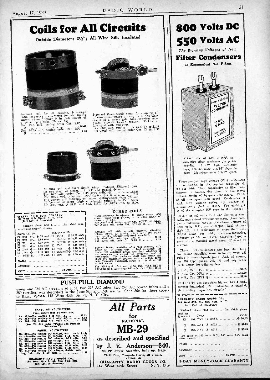
August 17, 1929 RADIO WORLD 21
Coils for All CircuitsOutside Diameters 21/2" ; All Wire Silk Insulated
Antenna coil for all circuits, interstageradio frequency transformer for all circuitsexcept where primary is in plate circuit of
a screen grid tube, 224 or 222.
For .0005 mfd. tuning order Cat. RF5$0.75
For .00035 mfd. tuning order Cat. RF30.80
Standard three -circuit tuner for coupling alltubes -except where primary is in the platecircuit of a screen grid tube-provides ade-quate, smooth tickler control. Tickler isfurnished with end -stop.For .0005 mfd. tuning order Cat. T5 @.$1.25For .00035 mfd. tuning order Cat. T3 @. 1.30
Antenna coil and three -circuit tuner, matched Diamond pair,
for one stage of screen grid RF and tickled detector.For .0005 mfd. order Cat. DP5 (two coils) @ $2.00
For .00035 mfd. order Cat. DP3 (two coils) @. 2.10
The screen grid 3 -circuit coil alone, distinguished from T5 and
T3 because of large (high impedance) primary, is Cat. SOTS
for .0005 mfd. @ $1.25, and Cat. SGT3 for .00035 mfd. @ $1.30.
SCREEN GRID COIL COMPANY,143 West 45th Street, N. Y. City
(Just East of Broadway)
Enclosed please find $ for which
Parcel post prepaid at once
IQun'ty-Cat. No. Qun'ty-Cat. No. I
O RF5 @...$0.75 each 0 SGT3 @ $1.30 each
O RF3 @... 0.80 each 0 SGRF5 @ 0.75 each
O T5 @... 1.25 each 0 SGRF3 @ 0.80 each
I0 T3 @... 1.30 each 0 TA5 @ 1.10 each
O DP5 @... 2.00 pair 0 VA3 @ 1.10 eachO DP3 @... 2.10 pair 0 BTSA&B@ 2.50 each
O SOT5 @... 1.25 each 0 BT3 @ 2.55 each
INAME
IADDRESS I
1...CL'Y STATE
send
OTHER COILSRadio -frequency transformer to couple screen gridstages, where large primary is in plate circuit ofscreen grid tube.For .0005 mfd. tuning order Cat. SGRF5 @ 80.75For .00035 mfd. order Cat. SGRF3 @ 0.80
Antenna coil with variable primary, affordingvolume control by turning rotary coil; two wind-ings, variable primary and fixed secondary.For .0005 mfd. order Cat. VA5 @ $1.10For .00035 mfd. order Cat. VA3 @ 1.15
Bernard- tuners, consisting of a fixed primary, withrotary coil in series with a fixed secondary, fortuning the combined rotary and fixed windings ofthe secondary, to exceed the broadcast band ofwavelengths. The condenser shaft and rotary coilshaft are physically coupled so one motion turnsboth. Increases wavelength range so it is about 150to 600 meters.For .0005 mfd. (Ant. coil) order Cat. BT5A @$2.50For .0005 mfd. (interstage SG) order Cat. BT5B $2.50
PUSH-PULL DIAMONDusing one 224 AC screen grid tube, two 227 AC tubes, two 245 AC power tubes and a280 rectifier, was described in the June 8th and 15th issues. Send 30c for these copiesto RADIO WORLD, 145 West 45th Street, N. Y. City.
PANEL AO VOLTMETERS(Panel meters take 2-3/64" bole)
No. 851 -For reading 0-15 volt. A() 42.2rNo. 853 -For reading 0-10 volts AO 2.26No. 858 -For reading 0-6 volt. AO 2.26
(See No. 848 under 'Pocket and PortableVoltmeters.")
PANEL VOLTMETERSNo. 885 -For reading DC voltages, 0-8 telt', $1.50No. 810 -For reading DC voltages, 0-19 volts. 1.00No. 818 -For reading DC voltages, 4-16 volt', 1.00No. 828 -For reading DC voltages, 0-6 volts. 1.00No. 887 -For reading DC voltages, 9-50 volts, 1.00No. 83$ -For reading DC voltages, 0-100 volts, 2.28No. 842 --For reading DC voltage., 0-155 volts, 2.25No. 840 -For reading DC voltages, double read-
ing, 1-8 volts. 0-100 volts 1.66
GUARANTY RADIO GOODS CO.,146 West 45th Street, New York City.
Just East of Broadway
All Partsfor
NATIONAL
MB -29as described and specifiedby J. E. Anderson -$40
245 PP Power Amplifier, built up, $55.00Thrill Box, Complete Parts, all 6 coils,
cabinet -$33GUARANTY RADIO GOODS CO.
145 West 45th Street N. Y. City
800 Volts DC
550 Volts ACThe Working Voltages of New
Filter Condensersat Economical Net Prices
Actual size of new 2 mfd. non -
inductive filter condenser for powersupplies. 2 1/2" high includinglugs, 1 3/16" wide, 1 3/16" front toback. Mounting holes 1 1/2" apart.
These compact high voltage (VII) condensers
are obtainable in the popular capacities @
85c per mfd. Their superiority as filter con-densers, of course, fits them for the lesservoltage strain of by-pass condensers. Think
of all the space you save! Condensers of
such high voltage rating are usually 6"
square for a block of three. You could get16 of the compact HV type in that space!
Rated at 800 volts D.C. and 550 volts rms.A.C., guaranteed working voltages, these com-pact condensers have a breakdown voltage of2,600 volts D.C., power factor (loss) of leisthan 1%, D.C. resistance of more than 600,-
000,000 ohms per mfd., are non -inductive,accurate to 5% and have mounting flaps, apart of the shielded metal case. Finished inmaroon.
These filter condensers are just the thingfor power supplies, even including four 250tubes in parallel -push pull! And, of course,for 210 type packs, 245, 171 and any otherpack using 550 volts or less.
1 mfd., Cat. HV12 mfd., Cat. HV2 @4 mfd., Cat. HV4 @
$0.85$1.70$3.40
[NOTE: To use capacities higher than 4 mfd.,connect individual HV condensers in parallel,thus adding capacities directly.]1M. 11111 om. MO. NMEN dm= MEI MN AMR MI MI
GUARANTY RADIO GOODS CO.,143 West 45th St., New York, N. Y.
(Just East of Broadway)
Enclosed please find $ for which Pleasesend meQuantity Type Price
O Cat. HV1 (1 mfd.) @ $0.85
O Cat. HV2 (2 mfd.) @ $1.70
O Cat. HV4 (4 mfd.) @ $3.40
All rated at 800 volts D.C., 550 volts A C. (rootmean square).
NAME
ADDRESS
CITY STATE
5 -DAY MONEY -BACK GUARANTY
22 RADIO WORLD August 17, 1929
Socket WrenchFREE!
One of the handiest tools for a custom setbuilder, service man or home constructor is aBERNARD socket wrench. It consists of a634" long metal tubing in which is a plunger,controlled by a knob. The plunger has a grip-ping terminal (called a socket, hence the name"socket wrench") that may be expanded orcontracted to tit 6/32, 8/32 and 10/32 nuts, themost popular sized nuts in radio. Use theknob to push out the plunger, press down onthe handle to grip the nut, then turn the nutto left for removal or to right for fasteningdown. Total length, distended, includingstained wooden handle, 10". Gets nicely intotight places. Send $1 for 8 weeks' mail sub-scription for RADIO WORLD and get thiswrench FREE. No other premium with thisoffer. Present subscriber may. extend subscrip-tion by stating he is one.
LACAULT'S BOOK"Super -Heterodyne Construction and Operation,"giving the master's most masterful expositionof the theory, performance and construction ofthis fascinating type of circuit, is a necessityto every serious radio experimenter. More than100 pages and more than 50 illustrations. Buckram cover. This book by R. E. Lacault, FREEIf you send $1.00 for an 8 -weeks subscriptionfor Radio World. Present subscribers may acceptthis offer. Subscription will be extended.
RADIO WORLD 145 W. 45th St., N.Y. CityDust East of B'way
High Resistance MeterSame Meter Reads Both AC anal DC
Accurate to 1 per cent.
The 0-600 volt AC and DC meter (Cat. No. 600),with 3 -ft. cord, de luxe tips and hanger $7.00.
TH.11 output voltages of all B eliminators, the voltagesof all B batteries, as well as the house current line
voltage, whether AC or DC, and the voltage across Doweltransformer secondaries, can be accurately measured ',this meter. The full scale is 0-600 volts, and Ws lam.meter measures both AC and DC.
GUARANTY RADIO GOODS CO.,145 West 46th Street, N Y. City.
(Just East of Broadway)
Your Choice ofThese Nine Meters FREE!
0-6 Voltmeter D.0 No. 320No. 337
8 -Nell Charge Tester D.0 No. 23No. 338
0-25 Milliamperes D.0 No. 3250-50 Milliamperes D.0 No. 3500.100 Milliamperes D.0 No. 3900-300 Milliamperes D.0 No. 3990-400 Milliamperes D.0 No. 394
0-50 Voltmeter D.0
0-10 Amperes D.0
Equip Yourself NowWith Necessary Meters!
To do your radio work properly you need meters. Bore isyour opportunity to get them at no extra cost. See the listof nine meters at left. Heretofore we have offered the °bolosof any one of these meters free with an 8 -weeks subscriptionfor RADIO WORLD, at $1, the regular price for suchsubscription. Now we extend this offer. For the first timeyou are permitted to obtain any one or more or all of thesemeters free, by sending In $1 for 8 -week's subscription, en-titling you to one meter; $2 for 16 weeks, entitling you totwe meters; $3 for 26 weeks, entitling you to three meters;$4 for 35 weeks, entitling you to tour meters; $5 for 44 weeks,entitling you to 5 meters; $6 for 52 weeks, entitling you tosix meters. Return this offer with remittance, and check offdesired meters in squares at left.
RADIO WORLD will help you in your radio work, soyou will be able to use the meters most valuably. Keepabreast of all the new circuits, intimate details on perfectingexisting sets, and get inside track on sensitivity, distancereception, tonal quality, and news of radio, technical and non-technicaL Enjoy the writings of Dr. Lee De Forest, McMurdoSilver, J. E. Anderson, Herman Bernard and a host of otherradio engineers who contribute their knowledge to you throughthe medium of RADIO WORLD, the first and only illustratednational radio weekly. You can find no magazine that bettercaters to your needs than RADIO WORLD. Short waves?RADIO WORLD will tell you all about them. Extremelysensitive broadcast receivers? Their construction and operationare fully discussed with confident regularity. Power supplies--push-pull or otherwise? AC receivers? Screen grid tubes?Large receivers that give a super -abundance of performance-small, economical receivers that give performance out of all. comparison to their size? Are you interested in these! Thenyou're interested in RADIO WORLD.
Present mail subscribers may renew their subscription underthis remarkably generous offer. Put cross in square. CI
RADIO WORLD145 W. 45th St., N. Y. City-Published Weekly.All Newsstands. 15s oar essy-.13, slx months -30 a yaw
Horn Unit $2.25
This unit is pre-eminent for horn -type speakers,such as the exponential horns or other long tone -travel horns. The faintest word from a "whisper-ing tenor" or the tumultuous shout of the crowdor highest crescendo of the band is brought outclearly, distinctly. Stands up to 450 volts with-out filtering. Works right out of your set'spower tube, requiring no extra voltage source.Standard size nozzle and cap are die-cast alu-minum, one piece, with milled platinum -likefinish. The casing is full nickel, of highest pos-sible polish. Works great from AC set, batteryset or any other set, push-pull or otherwise.
For Portable UseThis unit can be used in a portable without anyhorn attached and will give loud reproduction.Order Cat. 225, with 4% ft. cord attached .(Shipping weight, 2 lbs.) $2 25
Air -Column Horn8 -ft. tone travel molded wood horn (less unitNo. 225) is obtainable already mounted in abaffle box. Outside overall dimensions of bafflebox, 21,4" high, 18" wide, 15" front to back.Shipping weight, 27 lbs. Order Cat. 596 t $8.00.The 225 unit and 596 horn built into a ply -walnuttable ;xi" high, 24%" wide, 17%" front to back.Shipping weight, 50 lbs. Cat. No. 597 . . @ 420.00Acoustical Engineering Associates,145 W. 45th St., N. Y. City gust E. of Bway).
Please ship C. 0. D.0 Cat. No. 225 @ $2.25 0 Cat. No. 598 g $8.000 Cat. No 597 @ $20.00
Name
Address
City State
FIVE-DAY MONEY -BACK GUARANTEE
11111111.M11111111111.111.141M11111111111111111111111111111,11.111
Quick Action Classified AdsRadio World's Speedy Medium for Enterprise and Sales
10 cents a word - 10 words minimum - Cash with OrderLEADING CIRCUITS
DIAMOND OF THE AIR, SCREEN GRIDMODEL, battery operation, four tubes, described inFebruary 9th, 16th, 23d and March 2d issues, 1929.Send 50c for these four copies. Blueprint freewith 8 weeks' subscription to RADIO WORLDat $1.
AC DIAMOND, screen grid, 4 tubes, publishedin March 23d and 30th issues. Send 25c for thesetwo numbers. Blueprint free with 8 weeks sub-scription for RADIO WORLD at $1.
If you are renewing a present subscriptionplease so state.
RADIO WORLD, 145 W. 45th St., N. Y. City
RADIO RECEIVING TUBES, by Moyer andWostrel, first edition just off the press. No radioservice man, experimenter or student of radioshould be without this authoritative book on theprinciples and applications of vacuum tubes. Itanswers all your questions relating to receiving,amplifying and rectifying tubes. Price postpaid,$2.50 Radio World, 145 W. 45th St., New York
PATENT YOUR IDEAS. Easy terms. BookletFree. Established 25 years. H. Sanders, RandMcNally Building, Chicago. Ill.
RADIO TUBES, Screen Grid, 24's, A.C. $3.25.22's, D.C. $3.00. 27's, $1.50. 26's $1.30. 71's,$1.50. 80's, $2.00. 12's, $1.50.Filament transformers, 5, 2%, and PA volt wind-ings center tapped $4.00. Postpaid in U. S. D.McLarty, 926 Ardmore St., Jacksonville, Fla.
HELP WANTEDWANTED a radio engineer to assist an inventor.Must be a good mechanic, capable of designingand doing his own machine work and with in-ventive ability and vision to develop the idea.Address P. 0. Box 530, New Haven, Conn.
LOUDSPEAKERS TESTED and guaranteed, 24"diameter, contain powerful unit. $21.75. LemsersShop, 6326 Frontenac, Detroit, Mich.
AGENTS WANTEDCARTER WINDOW WASHER. Exclusive Dis-tributor wanted. BIG PROFITS. Cleans, Dries,Polishes, one operation. Territory closing fast.Act quick. CARTER PRODUCTS, 985% FrontStreet, Cleveland, Ohio.
LET US PUT YOUR SPEAKER ORYOUR SET IN SHAPE!
If your receiver or amplifier, no matter of whatkind, is not giving proper results, send it to us.prepaid. We will test it FREE and let you knowwhat's wrong, telling you cost of repairs. Outcharges are very reasonable. Six years' experi-ence. Loudspeakers and units repaired. Burnt -outcoils replaced. jaynxon Laboratories, 57 DeyStreet, New York City.
RADIO INTERFERENCE-Six ways to eliminateit. Instructions $1.00. Address, The Experimenter,67 Mosher Street, Holyoke, Mass.THRILL BOX of National Co., Cat. SW4C
all parts, including all six coils, 15 to 570 meters,and cabinet, $33. Wired by Abbott Laboratories$6 extra. P. Cohen. Room 1214. 145 W. 45th St.,N. Y. City. Come in and see it.
RADIO-Fastest growing business in the world.Are you sharing the profits? Let us show youhow. No selling. Free booklet. Radio Doctors,Inc., Dept. W. 131 Essex St., Salem, Mass.
August 17, 1929 RADIO WORLD
PEERLESS12" AC Dynamic Speaker in
SONORi iCatibe7AtOnly
LIST PRICE, $155.00
$37.50
TI e famous Peerless AC dynamic speaker, with Kuproxre tifier and 1,500 mfd. hum -killing condenser built in,al housed in this 40" high Sonora cabinet of fascinatingply -walnut. The cabinet is all one piece-carved legs,marqueterie panel and grille pillars.SI ding back is made of cane. This
%LPimposing floor model speaker, exactlyas illustrated, in original factory 0packing case, shipping weight 100lbs.
Amazing Buy!Never in your life did you hear of such anamazing bargain-highest class, perfect, guaran-teed merchandise at more than 75% off list price!Look at that beautiful highboy cabinet, itsgraceful legs, with archer's bow tiepiece; itsrosetted side panels at front, its shapely grillepillars, all in two-tone effect, with high -polishsu-face of walnut. The speaker sets against a
golden grille, with ample baffle board concealed.
Money -BackGuarantee!
Every precaution has been taken to produce the finestpossible tone. The speaker is the genuine famous Peer-less, operating directly from the 110 -volt 50-60 cycle ACline. The cane back leaves the cabinet acoustically open,to avoid box resonance. The entire outfit-speaker, recti-fier, 1,500 nor& condenser, AC cable, speaker cords andAC switch, all built up and wired-is sold only in thishandsome cabinet.
Order yours TODAY on a 5 -day money -back guaranteebasis. No C.O.D. orders filled.
ACOUSTICAL ENGINEERING ASSOCIATES,143 West 45th Street, New York, N. Y.Gentlemen: Enclosed please find $17.50 for which pleaseship by express at once one 12" diameter genuine Peer-less AC dynamic speaker, with built-in Kuprox dry rec-tifier, 1,500 mfd. hum -killing condenser, AC cable, speakercord, and AC switch built in, all contained in the Sonoraply -walnut highboy cabinet, with cane removable back;the cabinet consisting of one piece, ply -walnut; all in5riginal factory carton. No C.O.D.
Name
Address
City State5 -DAY MONEY -BACK GUARANTEE
[Radiofaft\ProfessionalsRadiotriciansConsultants
Service Men Manufacture
An InvitationA recent survey among the readers ofRADIO -CRAFT has disclosed the factthat our circulation is mostly amongprofessional radio men.
If These men naturally want to read andtalk "shop."
IT Our Magazine, starting with the Octoberissue, will be the romping ground ofradio technicians.
¶ We want to publish your experiences,your wishes, your constructive ideas.
11 Let the other fellow in the trade knowwhat's going on, so that the whole radiofraternity may benefit from it.
if Send us your articles, letters, experi-ences, questions, stories, etc.
IT We will pay you for every line published.
What Radio -Craft Readers WantArticles giving the professional radio man's
experience with radio sets, power amplifiers,talking sound film equipment, experience withtubes.
Service men, repair men, laboratory men andradiotriciarns very frequently develop and getup kinks and test sets that are short-cuts andare a great deal of help in their work. Yourco -readers want to know about this equipment,these short-cuts and your novel kinks. Whynot give them the benefit of your findings?RADIO CRAFT pays well for this work.
Send all contributions to:Editor
RADIO.CRAFT98 Park Place, New York
EngineersMechanicsDesigners
Contractorsrs Dealers
A Courtesy to theProfessional Radio ManIn order to make it possible for allRadio Technicians to read RADIO -CRAFT regularly, each month, wehave put into effect a special sub-scription price.The regular price of RADIO -CRAFT is $2.50 per year (12 is-sues). The newsstand rate is 25cents a copy.Any radio professional, sending ina subscription on, his letterhead,showing that he is engaged in somecapacity in radio work will receiveas a special courtesy
8 Issues for
RADIO.CRAFTfor $1.00
Just pin a dollar bill to the couponbelow and forward it with your let-terhead or business card. _ -RADIO -CRAFTRW-8, 98 Park Place,New York, N. Y.
Enclosed find $1.00 for which please enter mysubscription to Radio -Craft for eight months.
Name
Address
City State
Handiest thing for ANY short-wave adapter.socket of any short-wave adapter you
Put detector tube of your present set Inbuild, put plug in detector socket of your
broadcast receiver. Cable34". Leads identified bothby color scheme and tags5 -prong plug and S -lead
cable for ACshort waysadapter. Maybe used as5 - lead bat-tery oblsPlug withUY socket(C t. No.Z1AC)GREEN I, -prong extraplug onlynecessary ad -YELLOW ditloo te
other for battery short-wave adapter (Cat. No.21 -BAT) $0.50.Cat. No. Z1AC and A -BATordered together $1.75.
GUARANTY RADIO GOODS CO.145 WEST 45TH STREET New York CD -
PURPLE

RADIO WORLD August 17, 1929
New Style DeLuxe Leatherette Carrying Case FREEwith each Jiffy Tester!
This combination of meters tests all standard tubes, including the new AC screen grid tubes and thenew 245 tube, making thirteen tests in 41/2 minutes ! Instruction sheet gives these tests in detail.
\`, Ifti.
- . ,: . ,V 7\t,
\ )'
3An ;1'11.1Vl
..........
tak \
....................................
A PORTABLE testing laboratory is yourswhen you possess a combination Jiffy
Tester, for then you can measure the filament andplate voltages of all standard tubes, including ACtubes, and all standard battery -operated or AC screen gridtubes; also plate voltages up to 500 volts on a high re-sistance meter that is 99% accurate; also plate current.
The Jiffy Tester consists of a 0-20, 0-100 milliammeter, with change-over switch and a 0-10 volt AC and DC voltmeter (same meter readsboth), with two sockets, one for 5 -prong, the other for 4 -prong tubes;a grid bias switch and two binding posts to which are attachedthe cords of the high resistance voltmeter; also built-in cable with 5 -prong plug and 4 -prong adapter, so that connections in a receiver aretransferred to the Tester automatically. Not only can you test tubes,but also opens or shorts in a receiver, continuity, bias, oscillation, etc.The instruction sheet tells all about these tests.
In addition you can test screen grid tubes by connecting a specialcable, with clip to control grid (cap of tube) and other end of specialcable to the clip in the set that went to the cap before the tube wastransferred to the tester.
THE new carrying case, whick isfurnished FREE with each order
for a Combination Jiffy Tester, containsthe entire outfit, including the three meters,
cable and plug, and three adapters (one for 4 -prong tubes, two for 199 tubes). This case is 10%x
7yor.3%." and has nickel corner pieces and protective snap -lock. The case is made of strong wood, with black leatherette overlay.To operate, remove a tube from the receiver, place the cable plugto the vacant receiver socket, put the tube in the proper socket of
the Tester, connect the high resistance meter to the two binding posts,and you're all set to make the thirteen vital tests in 4% minutes!The Combination Jiffy Tester is just the thing for service men, cus-tom set builders, experimenters, students, teachers and factories. Order"Jiffy 500." The price is only $14.50.If a 0-600 AC and DC high resistance meter (99% accurate) isdesired, so house electricity line voltage and power transformer voltage.can be measured, as well as plate voltage, instead of the 0-500 DCvoltmeter, order "Jiffy 600" at $15.50.
GUARANTY RADIO GOODS CO., 145 W. 45 St., N. Y. City. (Just East of Broadway).0 Please ship at once on 5 -day money -back guaranty one "Jiffy 500," at $14.50, consisting of(1) One Two -in -One 0 to 10 voltmeter for AC and DC. Same meter reads both. Scale
especially legible at 1% to 7% volts. This meter reads the AC and DC filament voltages.(2) One DOUBLE reading DC milliammeter, 0 to 20 and 0 to 100 milliamperes, with change-
over switch. This reads plate current.(3) One 0-500 volts high resistance voltmeter, 99% accurate; with tipped 30" cord to measureB voltages.
(4) One 5 -prong plug with 30" cord for AC detector tubes, etc., and one 4 -prong adapter forother tubes.
(5) One grid switch to change bias. (9) One handsome moire metal case.(6) One 5 -prong socket. (10) One instruction sheet.(7) One 4 -prong socket. (11) One de luxe carrying case.(8) Two binding posts. (12) One screen grid special cable.0 If 0-300 DC high resistance 99% accurate voltmeter is preferred to 0-500, put check here.
Price is same, $14.50.0 Same as above, except substitute a 0 -600 -volt AC and DC high resistance 99% accuratevoltmeter (same meter reads both) for the 0-500 DC meter. Price $15.50.
NAME
ADDRESS.........................................................................................
CITY STATE
FIVE-DAY MONEY -BACK GUARANTYThe new de luxe leatherette carrying case iscompact and handy. Size 10%" long, 7%'wide, 3%" deep.