aug 1 2009 - us epa · 2-map pmap·. map projection utm lcc projection and grid feast false easting...
TRANSCRIPT
UNITED STATES ENVIRONMENTAL PROTECTION AGENCY
RESEARCH TRIANGLE PARK, NC 27711
AUG 3 1 2009
MEMORANDUM
SUBJECT: Clarification on EPA-FLM Recommended Settings for CALMET
TO: Regional Modeling Contacts
FROM: Tyler J Fox, Group Leader y~)-~ Air Quality Modeling Group, C439-m
OFFICE OF AIR QUALITY PLANNING
AND STANDARDS
The purpose of this memorandum is to update the draft recommendations for CALMET settings that were provided previously with the draft Reassessment of the Interagency Workgroup on Air Quality Modeling (JWAQM) Phase 2 Summary Report: Revisions to Phase 2 Recommendations (EPA, 2009).
On May 15, 2009, the EPA Model Clearinghouse issued a memorandum addressing a number of issues related to the operation of the CALMET diagnostic meteorological model in regulatory modeling applications for long-range transport (LRT). Additionally, a draft version of revisions to the existing IW AQM Phase 2 guidance was released on May 27, 2009 to provide technical context for the Clearinghouse memorandum. This draft document outlined a series of recommendations for CALMET settings that were intended to facilitate the direct "pass-through" of prognostic meteorological data to the CALPUFF modeling system using the same horizontal and vertical grid structure of the parent pro~nostic data set. This purpose is consistent with one of our overarching goals expressed at the 81 Conference on Air Quality Modeling promoting the use of prognostic meteorological model products in regulatory dispersion modeling applications.
Due to the time sensitive nature of the Clearinghouse memorandum, it was not possible to complete extensive testing of the recommended CALMET operational settings prior to release of the memorandum and draft IWAQM reassessment report. Subsequent testing of the CALMET model with the proposed settings against mesoscale tracer databases indicates that CALMET /CALPUFF performance using the draft recommendations deteriorates somewhat in comparison to other MM5/CALMET horizontal grid configurations that were tested. Specifically, testing against the Cross-Appalachian Tracer Experiment (CAPTEX) mesoscale tracer study dataset showed that when MM5 and CALMET were run on the same horizontal grid resolution, performance was poorer than other MM5/CALMET grid configurations tested. While the performance deterioration was not drastic, it was significant. These results have caused us to reconsider our interim guidance because it is inconsistent with our desire to promote the use ofboth the best meteorological products and prognostic data in general. The use of
1
Internet Address (URL) • http://www.epa.gov RecyclediRecyclable • Printed wHh Vegetable Oil Based Inks on Recycled Paper (Minimum 25% Postconsumer)

CALMET as. a vehicle to "pass-through;' MMS or other numerical weather prediction (NWP) model data is no longer considered viable.
The EPA has dedicated considerable time and resources to the evaluation of the use ofNWP data in conjunction with the CALMET/CALPUFF modeling system. As discussed in the draft IWAQM reassessment report, there are technical limitations to the applicability of diagnostic wind field models that together with advances in NWP model technology and resolution make the fuller use ofNWP model data an attractive alternative. The draft IW AQM reassessment document also discusses EPA's intention to transition to the full use ofNWP model data rather than continue reliance upon wind fields from DWMs for LRT applications. Therefore, rather than continue to dedicate time and resources to evaluating configurations for CALMET that would facilitate a direct "pass-through" ofNWP data, EPA will focus its efforts toward expediting the testing and review of its MMS/WRF-to-CALPUFF software prototype discussed at the 9th Conference on Air Quality Modeling in anticipation of an early 201 0 release.
In the interim, a revised series of recommendations for CALMET settings were agreed upon during a recent meeting with modelers from EPA and the Federal Land Manager (FLM) community .. Therefore, as discussed during the EPA modelers' conference call on August 19t\ . the EPA Model Clearinghouse is providing all of the Regional Modeling Contacts with the attachedrevised list of recommended switch settings for CALMET. These recommendations are based in large part upon the understanding we have developed from the numerous tracer evaluations we have conducted in addition to the collective experience of the National Park Service, Forest Service, and US Fish and Wildlife from the BART process. In general the recommendations are based upon values from the VISTAS BART modeling protocol with limited modifications based on our internal testing. ·
~ . . As attached, these updated recommendations supersede the recommendations from the draft IW AQM reassessment report. While the draft IWAQM recommendations intended to configure CALMET to facilitate a direct "pass-through" ofMMS data are no longer considered viable, our position regarding grid resolution presented in the May 15, 2009, Model Clearinghouse
\ - I . ( •
memorandum have not changed. ·In particular, we wish to call to your attention that in most circumstances it is considered inappropriate to consider CALMET horizontal grid resolutions of less than four (4) kilometers, consistent with our discussion in the May 15, 2009 Model
· Clearinghouse memorandum. It is anticipated that the FLMs will likewise require adherence to these recommendations for modeling conducted pursuant to the Class I AQRV requirements of the PSD program. In those cases, it is important to remember that the FLMs have the affirmative responsibility for AQRV related studies, and usually take the lead in negotiating the protocol for model settings (per Section 6.2.3 of the Guideline on Air Quality Models, Appendix W to 40 CFR Part 51). \
2

REFERENCES
USEPA, 2009: Reassessment of the Interagency Workgroup on Air Quality Modeling (IWAQM) Phase 2 Summary Report: Revisions to Phase 2 Recommendations (Draft). EPA- EPA-454/B-09-XXX, Research Triangle Park, NC, 56 pp.
cc: Richard Wayland Bill Harnett Raj Rao DanDeroeck Roger Brode Bret Anderson John Vimont Tim Allen John Notar RickGraw
3

Input Group Subgroup
0 -lilputand a output file names -
-
b
c
d '
e
f
EPA-FLM Recommended CALMET Input File Values August28,2009
Variable Description Default
GEODAT Input filename of geophysical data rGEO.DAT
SRFDAT Input filename of hourly meteorological data SURF.DAT
CLDDAT Input filename of giidded cloud data CLOUD.DAT ./
PRCDAT Input filename of hourly precipitation data PRECIP.DAT
WTDAT Input filename of gridded fields of terrain weighting factors WT.DAT
METLST Output filename of list file CALMET.LST
METDAT Output filename of generated gridded met fields CALMET.DAT
PACDAT Output filename of generated gridded met files (MESEOPUFF II) PACOUT.DAT
LCFILES Convert names to upper or lower case User defined -~
NUSTA Number of upper air stations ' User defined
NOWSTA . Number of over water met stations User defined
' NM3D Number of MM4/MM5/3D.DATfiles User defined
NIGF Number of coarse grid CAL MET fields a~ initial gueSs fields User defined
UPDAT Input filenames of upper air data UPn.DAT (n'=1,2,3 ... )
SEADAT Input filename of over water stations SEAn:DAT (n=1,2,3; .. ) ·
M3DDAT Input filename of MM4/MM5i3D.DAT - MMSOn.DAT
IGFDAT Input filename of IGF-CALMET files IGFn.DAT (n=1,2,3 ... )
DIAOAT Input filename of preprocess~ sfc/UA data DIAG.DAT
PRGDAT Input filename of prognostic gridded wind fields PROG.DAT
TSTPRT Output filename of intermediate winds, and misc ... etc TEST.PRT
4
EPA-FLM
User defined
User defined
User defined
User defined
User defined
T
User defined (>0)
User defined
User defined (>0)
0
user defined
User defined
User defined
-

-
Input Group Subgroup Variable - Description Default EPA-FLM
TSTOUT ·Output filename of final wind fields TEST.OUT /
' - TSTKIN Output filename of wind fields after kinematic winds TEST.KIN I
TSTFRD Output filename of winds after Froude Number effects - TEST.FRD /
' TSTSLP - Output filename winds after slope effects TEST.SLP
- DCSTGD- Output filename ofdistance land internal variables DCST.GRD
·. 1- General ._IBYR Beginning year User defined User defined run and
/
C:ontrol IBMO Beginning month User defined User defined param~ers -
IBDY Beginning day User defined User defined . _; IBHR Beginning hour User defined .User defined
IBTZ Base time zone User defined User defined
IRLG Length of run (hours) User defined User defined
IRTYPE Output type to create ~ 1 '
LCALGRD Require fields forCALGRID T T
ITEST · Flag to stop run after setup phase 2 2
MREG Conformity to regulatory values User defined 1
2- Map PMAP·. Map projection UTM LCC projection and grid FEAST False Easting at projection origin {km)· 0.0 0.0 control parameters FNORTH False northing at projection origin (km) 0.0 0:0 .·
IUTMZN UTM zone User defined -999 . '
UTMHEM . Hemisphere of UTM projection N· N . . .
RLATO Latitude of projection origin (decimal degrees- Nf User defined User defined
RLONO Longitude of projection origin (decimal degrees- W) User defined User defined·
XLAT1 Matching latitude for projection (decimal degrees- N) . User defined User defined
5

~
"-
Input Group Subgroup Variable Description Default EPA-FLM
. XLAT2 Matching latitude of projection (decimal degrees- N) User defined User defined
' Datum Datum-region of output coordinates WGS-84 User defined
NX Number of east to west or X grid cells User defined User defined ~
NY - Number of north to south or Y grid cells User defined · User defined
DGRIDKM Grid spacing in kilometers (km) User defined User defined ( ~km )
XORIGKM Southwest corner of grid cell (1,1), X-coordinate (km) User defined User defined
YORIGKM Southwest corner of grid cell (1,1}, Y-coordinate (km) User defined User defined
NZ Nu'mber of vertical layers User qefined 10
ZFACE Cell face heights in arbitrary vertical grid (ZFACE (NZ+1)) (m) User defined 0,20,40,80,160,320, --- 640,1200,2000,3000,
4000
3- Output LSAVE Save met fields in unformatted file T T options
IFORMO Type of unformatted output file . 1 1
./. LPRINT Print met fields F F
IPRINF Print interval in hours 1 1
IUVOUT Layers of U, V wind components to print (IUVOUT (NZ)) NZ*O 10*0
IWOUT Levels of W wind component to print (IWOUT (NZ)) NZ*O 10*0 j
!TOUT Levels of 3-D temps to print (ITOUT (NZ)) NZ*O 10*0
STABILITY Print PGT Stability 0 0
USTAR Print friction velocity 0 0
MONIN Print Monin-Obukhov "
0 0
MIXHT Print mixing height 0 .
0 I I WSTAR Print convective velocity scale 0 0
PRECIP Print precipitation· rate / 0 0
6
'--
Input Group Subgroup Variable Description Default EPA-FLM
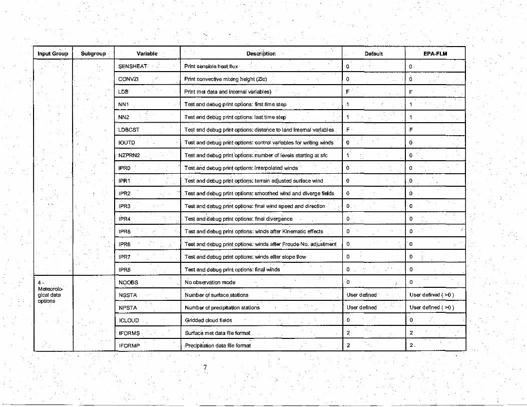
SENSHEAT Print sensible heat flux 0 0
CONVZI / Print convective mixing height (Zic) 0 0
LOB Print met data and Internal variables) .F F
NN1 Test and debug print options: first time step 1 1
NN2 Test and debug print options: last time step 1 1
LOB CST Test and debug print options: distance to land internal variables F F
I
IOU TO Test and debug print options: control v~riables for writing winds 0 0 I I
NZPRN2 Test and debug print options: number of levels starting at sfc 1 0 -
'
I PRO Test and debug print options: interpolated winds 0 0
IPR1 Test and debug prir:Jt options: terrain adjusted surface wind 0 0 !
' IPR2 Test and debug print options: smoothed wind and diverge fields 0 0
,"----.._
IPR3 Test and debug print options: final wind speed and direction 0 0 . • ..
IPR4 Test and debug print options: final divergence 0 0
IPR5 Test and debug print options: winds after Kinematic effects 0 0
IPR6 Test and debug print options: winds after Froude No. adjustment 0 0
IPR7 Test and debug print options: winds after slope flow 0 0
IPR8 Test and debug print options: final winds 0 0
4- NOOBS No observation mode 0 J 0 Meteorolo-gical data NSSTA Number of surface stations User.defined · User defined ( >0 ) options
NPSTA Number of precipitation stations User defined User defined ( >0 )
I CLOUD Gridded cloud fields 0 0
I FORMS Surface met data file format 2 ' 2 ~
IFORMP Precipitation data file format 2 2 ---- -
7

Input Group Subgroup Variable Description Default EPA-FLM ~
IFORMC Cloud data format 2 2 ~
5- Wind IWFCOD Wind model options 1 1 field options and IFRADJ Compute Froude number adjustment effects ~, 1 1 parameters
I KINE Compute Kinematic effects 0 0
IOBR Use O'Brien procedures for adjust vertical velocity 0 0
I SLOPE Compute slope effects 1 1
IEXTRP Extrapolate sfc;: wind obs to upper levels -4 -4
I CALM Extrapolate sfc winds even if calm ' 0 0
BIAS Surface/upper weighting factors (BIAS (NZ)) NZ*O 10*0
RMIN2 Minimum distance for extrapolation of winds 4 -1
IPROG Use prognostic model winds as input to diagnostic wind model 0 14 ,~
ISTEPPG Timestep (hours) of prognostic model data 1 1
IGFMET Use coars~CALMET fields as initial guess 0 0
LVARY Use varying radius of influence F F
RMAX1 Maximum radius of influence in surface layer (km) User defined 100
RAMX2 Maximum radius of influence over land aloft (km) User defined 200
RMAX3 ' Maximum radius of influence over wat~r (km) User defined 200 '
RMIN Minimum r~dius of influence in wind field interpolation (km) 0.1 0.1 '
TERRAD Radius of influence of terrain features (km) User defined 15
R1 Relative weight at surface of 1"1 guess fields and obs (km) User defined 50
/ R2 Relative weight aloft of 1"1 guess fields and obs (km) -~
User defined 100 i
!
RPROG Weighting factors of prognostic wind field data (km) User defined 0
~ ' ' ' DIVLIM Maximum acceptable divergence 5.0E-06 5.0E-06
8
Input Group Subgroup Variable '
Description Default EPA,FLM
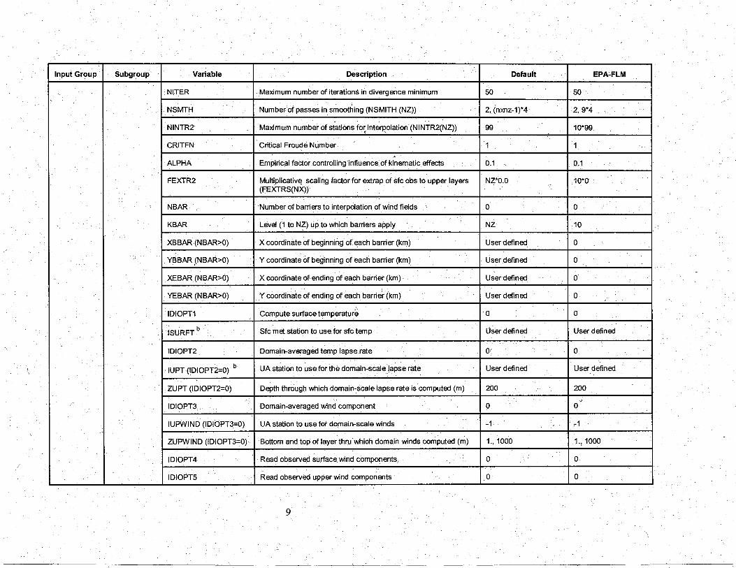
NITER Maximum number of iterations in divergence minimum 50 50 '
NSMTH Number of passes in smoothing (NSMITH (NZ)) 2, (nxnz-1)*4 2, 9*4
NINTR2 Maximum number of stations fo~ interpolation (NINTR2(NZ)) 99 10*99
CRITFN Critical Froude Number 1 1 I
ALPHA Empirical factor controlling influence of kinematic effects 0.1 0.1
FEXTR2 Multiplicative scaling factor for extrap of sfc obs to upper layers NZ*O.O 10*0 (FEXTRS(NX))
\ NBAR Number of barriers to interpolation of wind fields 0 0
KBAR Level (1 to NZ) up to which barriers apply NZ 10
- XBBAR (NBAR>O) X coordinate of beginning of each barrier (km) User defined 0
' YBBAR (NBAR>O) Y coordinate of beginning of each barrier (km) User defined 0
XEBAR (NBAR>O) X coordinate of ending of each barrier (km) User defined 0
YEBAR (NBAR>O) Y coordinate of ending of each barrie~ (km) User defined ·0
'-IDIOPT1 Compute surface temperature 0 0
ISURFT b Sfc met station to use for sfc temp User defined User defined
IDIOPT2 Domain-averaged temp lapse rate or 0
IUPT (IDIOPT2=0) b UA station to use for the domain-scale lapse rate User defined User defined
ZUPT (IDIOPT2=0) Depth through which domain-scale lapse rate is computed (m) 200 200
v
IDIOPT3 Domain-averaged wirid component 0 0
!UPWIND (IDIOPT3=0) UA station to use for domain-scale winds -1 "1
ZUPWIND (IDIOPT3=0) Bottom and top of layer thru which domain winds computed (m) 1., 1000 1.! 1000
IDIOPT4 Read observed surface. wind components/ 0 0
IDIOPT5 Read observed upper wind components 0 0
9

_j
Input Group Subgroup Variable - Description Default ~c
EPA-FLM
LLBREZE Use lake breeze module F F
NBOX Number of lake breeze regions User defined 0 ,,,
XG1 X grid line 1 defining the region of interest User defined 0
j '· .,
XG2 X grid li'ne 2 defining the region of interest User defined 0
YG1 y grid line 1 defining the region of interest User defined 0 /'
YG2 Y grid line 2 defining the region of interest User defined 0
XBCST X point defining the coastline (km) User defined 0
YBCST · Y point defining the coastline (km) User defined 0
XECST X point defining the. coastline (km) User defined 0
YECST Y point defining the coastline (km) User defined 0
NLB Number of stations in the region (sfc +upper air) User defineid 01
METBXID Station ID's in the region (METBXID (NLB)) User defined 0
' 6- Mixing CONSTB Mix ht constant: neutral, mechanical equation 1.41 1.41. height, temperature CONSTE Mix ht constant: convective equation 0.15 0.15' and precipitation CONSTN Mix ht constant: stable equation 2400 2400 parameters
CONSTW Mix ht equation: over water 0.16 0.16 ~ .... ..
FCORIOL Absolute value of Coriolis parameter 1.0E-04 1.0Ec04
IAVEZI Spatial averaging of Mix ht: conduct spatial averaging 1 1
MNMDAV Spatial averaging of Mix ht: Max,search radius(# of grid cells) 1 1
HAFANG Spatial avg'n of Mix ht: 0.5-angle of upwind cone for avg (deg) 30~ 30
ILEVZI Spatial averaging of Mix ht:. Layer of winds used in upwind 1 1
IMIXH Zic Mix Ht Options: Method to compute Mix ht 1 -1 ~-
10

Input Group Subgroup Variable Description Default EPA-FLM · ~
THRESHL Zic Mix Ht Options: Threshold buoyancy flux reqrd to sustain 0.05 0.0 over land (W /m3)
THRESHW Zic Mix Ht Options: Threshold buoyancy flux reqrd sustain over 0.05 0.05 water (W /m3)
ITWPROG Zic MiX-Ht Options: Overwater lapse rates used in Zic growth 0 0
ILUOC3D Zic Mix Ht Options: Land use category in 3D.DAT 16 16
DPTMIN Min potential ~mp lapse rate in stable layer above Zic (deg- 0.001 0.001 Kim)
' DZZI Depth of computing capping lapse rate (m) 200 200
ZIMIN Minimum over land mixing .height (m) 50 50
ZIMAX Maximum over land mixing height (m) 3000 3000
' ZIMINW Minimum over water mixing height (m) 50 J 50
ZIMAXW Maximum over water mixing height (m) 3000 3000
ICOARE Over water surface fluxes methods and parameters 10 0
DSELF Coastal/shallow water length scale (km) -, 0 0 ' '
IWARM COARE warm layer computation 0 0 '
J
I COOL COARE cool skin layer computation 0 ., 0 I I
ITPROG 3D temp from obs or from prognostic data 0 0 I I
IRAD Temp interpolation type • 1 1
TRADKM Radius of influence of temp interpolation (km) 500 500
NUMTS Max number of stations to. include in interpolation 5 5
lA VET Conduct spatial averaging of temp 1 1
TGDEFB Default temp gradient below mix ht over water (deg-K/m) -0.0098 -0.0098. '
TGDEFA Default temp gradient above mix ht over water (deg-K/m) -0.0045 -0.0045
11

Input Group Subgroup Variable Description Default EPA-FLM .·
JWAT1 Beginning land use categories for temp interpolation over water User defined - 999 55
JWAT2 Ending land use categories for temp interpolation over water User defined - 999. -55
NFLAGP Method of precipitation interpolation - 2 2
SIGMAP Radius of influence for precipitation (km) 100 - 100
CUTP Minimum precipitation rate cutoff (mm/hr) 0.01 .01
7 -Surface CSNAM Station name User defined User defined meteorolo-gical station IDSSTA Station identification number User defined User defined parameters
XSSTA X-coordinate (km) User defined User defined
YSSTA Y-coordinate (km) User defined User defined /
XSTZ Time zone User defined User defined
ZAN EM Anemometer. height (m) User defined User defined
8- Upper air CUNAM Station name User defined meteorolo-gcal station IDUSTA Station identification number User defined parameters
XUSTA X-coordinate (km) ~ User defined '
YUSTA Y-coordinate (km) User defined
UUTZ Time zone User defined
9-. CPNAM Station name User defined User defined Precipitation station IDPSTA Station identification number User defined User defined parameters
XPSTA X-coordinate (km) · User defined User defined
YPSTA Y-coord.inate (km) User defined User defined
12