audio restoration, enhancement & authentication terminology
TRANSCRIPT

Diamond Cut Productions, Inc. Application Notes
AN-20
Audio Restoration, Enhancement & Authentication Terminology Copyright © 1993 - 2019, Diamond Cut Productions, Inc.
This document provides basic definitions of some of the terminology found in the Diamond Cut
Productions family of Digital Signal Processing (DSP) software products. These terms are used
in the program proper as well as in their help-files and the user’s manuals.
Acoustical Impedance
Acoustical impedance is the total opposition provided by acoustical resistance and reactance to the flow of an
alternating pressure applied to a system. More specifically, it is the complex quotient of the alternating pressure
applied to a system by the resulting volume current. The unit of measurement is the Acoustical Ohm.
Acoustical Reactance
Acoustical reactance is the imaginary part of the acoustical impedance. Energy is not dissipated by acoustical
reactance; it is only stored there. The unit of measurement is the Acoustical Ohm.
Acoustically Mastered
Acoustically mastered record recordings utilized only the energy of the sound waves created by the sound source to
modulate the master cutting lathe stylus. This recording technique had none of the benefits which signal amplification
can provide to the recording process. This is the method that was utilized from the time of the invention of the
phonograph by Thomas Edison in 1876 up until around 1925, when vacuum tube amplifiers and microphones began
to be employed in the mastering process. By 1929, all of the major record companies had switched over to the
"electrical process" of record mastering.
Acoustical Resistance
Acoustical Resistance is the real term of the acoustical impedance relationship. This is the term responsible for the
dissipation of energy. The unit of measurement is the Acoustical Ohm.
A-D Converter
A device used to convert analog signals into digital (discrete time) signals, so that they can be signal processed by a
computer algorithm. The sound card in your computer contains an A-D converter and also a D-A (Digital to Analog)
converter. To be compatible with DCArt10/DC Forensics10, it must have at least 16-bit resolution to realize the
performance of the product. However, the software does support 8 through 24 bit resolution sound cards. In other
words, your sound card must be able to divide the amplitude of audio signals into numerically sampled representations,
the smallest division being one part in 65,536 (2^16). 16 bit audio has the same resolution as "red book" CD Audio.
A-law Compression
This is a slight variation of Mu-law compression, which is used in Europe. For more information, please refer to Mu-
law Compression. DCArt10 & DC Forensics10 support this format.
ADPCM
(Adaptive Differential Pulse Code Modulation)
ADPCM is a data compression method in which an audio signal is quantized by the difference between the input
reference signal and a prediction that has been made of that same signal. When the prediction between the actual and
the predicted audio signal exhibits bits having a low variance, it is accurately quantized and fewer bits are required
for digitization compared to standard PCM. Your software supports this file format.

AES
The Audio Engineering Society
60 East 42nd Street, Room 2520
New York, NY
10165-2520
USA
1-212-661-8528 / http://www.aes.org
AGC or ALC
Automatic Gain (AGC) or Level Control (ALC). This is a set of algorithms, which can be found in the Dynamics
Processor and Punch & Crunch effects that maintain the system gain at a relatively constant value independent of
input signal level. Signals below a set threshold value are upwardly expanded while signals above that threshold are
compressed. This is particularly useful in forensics applications wherein the various parties who are communicating
with one another are recorded at greatly varying relative levels.
AIFF
AIFF is the acronym for a PCM (Pulse Code Modulation) audio file format known as “Audio Interchange File
Format”. It is used primarily on the Macintosh platform. DCArt10 and DC Forensics10 facilitates conversions from
this format to .wav.
Aliasing (Temporal Aliasing)
In sampled data systems, aliasing can occur on signals higher than the Nyquist frequency. These are not real
representations of the source material. They could be looked at as parasitic signals or digital artifacts. For example,
if an audio system is sampling data at 44.1 kHz, its Nyquist frequency is 22.05 kHz. If an audio signal exists at 23
kHz, an alias signal will be produced at the difference between those two (or 0.95 kHz). That 0.95 kHz signal would
sound like a digital artifact to the listener (and be quite unpleasing). An anti-aliasing (brick wall) filter is usually
applied to the signal before the A/D conversion process to avoid this problem. In the example above, the brick wall
anti-aliasing filter would be set for around 22 kHz.
Algorithm
An algorithm is a step-by-step procedure for solving a mathematical problem.
Ampere
(I)
The unit of electric current that is equal to one Coulomb of electric charge flowing per second.
I = V / R,
wherein:
V = Voltage in Volts,
and
R = Resistance in Ohms
(also, see Ohms Law.)
Amplifier
An amplifier is an electronic system which enables an input signal to control power from a source independent of the
signal and thus be capable of delivering an output that bears some relationship to, and is generally greater than the
input signal. An audio amplifier performs this function producing a relatively linear relationship between the input
signal and the output signal. For more information on audio amplifiers, refer to Pre Amplifier and Power Amplifier
in the Glossary section of the Help File.

Amplitude
Amplitude is the loudness (or intensity) of a sound at any given moment in time, which is represented on the vertical
axis of the Diamond Cut time domain workspace areas. Amplitude in audio terms is usually expressed in relative
terms (the ratio of two levels) in dB (decibels), although sometimes it may be represented in absolute terms such as
Volts or SPL (Sound Pressure Level).
Amplitude-Frequency Distortion
Amplitude-Frequency distortion is a deviation from a perfectly flat frequency response over a range of interest
(usually 20 Hz to 20 kHz).
Amplitude Modulation (AM)
Amplitude Modulation is a technique for producing a radio carrier containing an audio signal in which the envelope
of the carrier is varied in amplitude in proportion to the level of the audio modulating signal. With Amplitude
Modulation transmission, the rate at which the carrier amplitude changes is proportional to the audio modulation
frequency. AM carriers are ideally fixed (constant) in frequency.
Analog
An electronic system in which signals are represented, amplified, and processed utilizing continuous Voltages and/or
currents (whose value could be expressed as an irrational number at any point in time) which are not quantized.
DCArt10/DC Forensics10 utilizes many digital simulations of analog systems within its algorithms.
Aromatic
Solvents that are made up of cyclic hydrocarbons or their derivatives such that, after they evaporate, tend to leave little
or no residue on the surface on which they had been applied.
Attenuate
Attenuation is the process of signal reduction, which is the opposite of the process of signal amplification. Most filters
attenuate signals outside of their pass-band and feed signals through with no attenuation (or amplification) within their
pass-band. Some filters, such as parametric and graphic equalizers are configured to provide either amplification or
attenuation at any given frequency. Devices such as volume control potentiometers, "L" Pads, "T" Pads and "H" Pads
are used to attenuate signals independent of frequency, i.e. flat. "L" Pads hold either the input or the output impedance
constant as the attenuation factor is modified. "T" Pads hold both the input and the output impedance constant as the
attenuation factor is changed. "H" Pads perform the same function as "T" Pads, only for balanced line systems. See a
table of resistance multipliers for a symmetrical (equal input and output impedance) “T” Pad attenuator in the Charts,
Graphs and Other Useful Info section of this User’s Guide.
Audio Frequency Spectrum
The range of frequencies between 20 Hz and 20 kHz. A very high quality audio system capable of reproducing this
frequency range should be able to do so within +/- 3 dB.
Azimuth
When analog magnetic tapes are recorded or reproduced, the gap of the respective head (recording or playback) should
ideally be perfectly normal (perpendicular) to the direction of the tape movement. If, in either
of the two mentioned processes, the respective head gap is off-normal (off-azimuth,) two types of signal degradation
will occur. The first phenomenon results in the loss of the high-end of the audio spectrum frequency response. The
second effect produces a phase shifting of one channel with respect to the other, thereby "smearing" the stereophonic
image. A similar phenomenon occurs when a monophonic half-track reel-to-reel tape is reproduced on a quarter track
machine. Azimuth problems can be corrected to some degree by utilizing the "Time Offset" feature found in the File
Converter, which is found under the Filter Menu.
Band-pass Filter
A Band-pass filter allows only a range of frequencies to be passed from its input to its output without attenuation. A
wide Band-pass filter is one in which an upper and a lower corner frequency need to be defined, and often several
octaves will be passed in between without attenuation. A narrow Band-pass filter is one in which only a center

frequency needs to be defined, and often has a bandwidth of an octave or less. The center frequency for a narrow
Band-pass filter is sometimes referred to as its resonant frequency. There are different Band-pass shapes that can also
be defined for narrow Band-pass filters.
Band-stop Filter
A Band-stop filter provides the inverse response of a Band-pass filter. You can find a Band-stop filter within the
Brick Wall filter suite found under the Forensics menu of your software.
Berliner, Emile
Emile Berliner is widely known as the one who commercialized the lateral cut disc record format. He first introduced
his products into the market place in 1895, although he had spent the previous 10-year period developing his system.
However, Emile Berliner was not the inventor of the disc format or the lateral cut method for creating the undulations
on a surface. These principles were outlined in the earlier Edison phonograph patents.
Blast
"Blast" is a term that is used to describe a passage of sound on a recording which is disproportionately louder (and
often distorted) compared to the rest of the recording. "Blasts" can be created by poor instrument placement on
acoustic recordings, poor mixes on electrical recordings, or by poor planning of microphone placement in live
recordings. The term "blast" was used by recording engineers at least as early as the 1920's.
Blue Amberol
Blue Amberols were the third (and final) generation of cylinder records which the Edison Company commercialized.
They were about 4 minutes in length. These records were made of a celluloid recording surface mounted on a plaster
of Paris core. They were an improvement on the Edison Gold Molded black wax cylinders, which were only two
minutes in length. The rotational speed for Blue Amberols (and black wax cylinders) is 160 RPM.
Broadcast Wave (.wav) Format (BWF)
Broadcast Wave or BWF (.wav) is an audio file format that facilitates the inclusion of certain metadata within a .wav
file header. It adds a “Broadcast Audio Extension” chunk to the basic Microsoft .wav format. It is a European
standard per EBU document Tech 3285, version 1 (July 2001). BWF provides a seamless exchange of audio data
between differing broadcast environments and equipment based on varying computer platforms. This format is
supported by your Diamond Cut software program. You can create BWFs via the Save As feature found within the
File Menu. You can edit the BWF header information via a dialog box within the Edit Menu. Complete information
regarding this format is beyond the scope of this document and can be found on the internet.
Brown Noise
Brown noise is a form of random noise exhibiting a Gausian distribution, which mimics Brownian motion. Its power
spectrum is proportional to 1 / f^2, exhibiting a – 6dB / Octave slope. Your Diamond Cut software can produce Brown
noise via two steps. First, create a random noise file using the Make Waves Generator. Then, bring up the
LIVE/Multi-Filter and apply the preset called “White to Brown Noise Converter”.
Buffer
A buffer is a memory sector that is used as a temporary storage location during input and output operations. The
"preview buffer" length is programmable in DCArt10/DC Forensics10, and is found in the Preferences section of the
Edit Menu.
Butterworth Filter
A Butterworth Filter produces a maximally flat amplitude characteristic in the pass band or the reject band (depending
on whether it is used as a Band-pass or a notch filter). Its characteristic also applies to higher order (2nd order or higher,
IIR type) high-pass and low-pass filters. It produces a critically dampened response at their corner frequency(s),
having no ripple, and therefore it introduces little distortion into the signal that is feeding it. The Butterworth filter’s
poles of signal transmittance are uniformly spaced on a semicircle, having its center on the imaginary axis. Its half-
power frequencies are those at which the circle intersects the imaginary axis. The low-pass, high-pass, and band-pass
filters offer the Butterworth response as an option.
Buzz

Buzz usually refers to a series of harmonic noise signals related to the frequency of the AC power mains. It differs
from "Hum" in sound, because it usually contains a large number of higher frequency harmonics (created by phase
controlled lighting dimmers or other non-linear systems connected to the power line). Buzz is best attenuated using
the Harmonic Reject filter, the Spectral Filter or either the Expert Impulse or Narrow Crackle Filter(s).
Byte
An eight-bit word. Each sample of a monophonic .wav file is generally represented by two eight-bit bytes. Two eight-
bit bytes are used to represent all of the integer numbers between 0 to 65,535 (actually +/- 32,768), which is the total
dynamic range of DCArt10/DC Forensics10 when it is operating in 16-bit mode.
1 Kilobyte (or 1 Kbyte) = 1,024 bytes
Capacitance
(C)
Capacitance is the ratio of the electric charge given to a body compared to its resultant change of potential. It is
usually expressed in Coulombs of charge per Volt of potential change and its basic unit is the Farad. Energy is only
stored (but not dissipated) in theoretical (ideal) capacitance. Time constants for audio filters are created with a
combination of resistors and capacitors in various configurations. High-pass, Low-pass, Band-pass, and Notch filters
can all be created with the appropriate combinations of resistors, capacitors, and amplifiers (usually op-amps). The
corner frequency for a simple first order RC filter = 1 / 2 pi* (R x C). The principle of capacitance (and conservation
of charge) is involved in the operation of condenser and electret microphones and electrostatic loudspeakers and
headphones.
F = (Farad) and F = micro Farad
F = 1 X 10 ^ -6 Farads
pF = 1 X 10 ^ -12 Farads
*Note: pi = 3.141592654 (approximately)
Cassette Tape Equalization Time Constants
Compact Cassette tapes (which operate at 1 7/8 ips) commonly utilize one of the following two equalization time
constants based on the tape type:
1. Normal (IEC Type 1) (Usually Ferrous Oxide based): 120 Sec
2. High (IEC Type 2) (Usually Chromium Oxide based): 70 Sec
Cent
1,200 cents = 12 semitones = 1 Octave in the scale of “Just Intonation”. In other words, the interval between two
tones whose basic frequency ratio is the twelve-hundredth root of two is the “cent”.
Cepstrum (Power)
Power Cepstrum displays are a way of graphically representing speech patterns using a specialized transform of an
audio signal. It is not a reversible transform. It produces a unique view of the information relating various frequency
bands associated with a signal and is useful for separating vocal tract information from the exciting pitch in voiced
speech. Mathematically, the Power Cepstrum of a Signal = |Flog(|Ff(t)|²)|². You can create cepstrum graphs using
your DC Forensics10 version of this software package. The feature is found under the Forensics Menu under the
Voice ID feature.
Cepstrum (Complex)
A Complex Cepstrum is a reversible transform and can be useful for the graphic display of the vowel sounds produced
by the human voice. It is also useful in identifying echoes created by acoustics in a room. Mathematically, the
Complex Cepstrum = FT (log)|FT(f(t))|) + j2πm) where FT is the signals Fourier Transform and m is the integer value
needed to unwrap the imaginary component of the complex log function. The horizontal axis is called the quefrency
which is related to the rate of occurrence of a particular harmonic contained within the signal. This transform is

implemented in the Voice ID feature found under the Forensics Menu of the DC Forensics Audio Laboratory version
of this software.
Charge (Coulombs)
Charge in units of Coulombs is the product of Voltage & Capacitance (Q = CV). Also, refer to “Ampere” for the time
relationship of the Coulomb..
Compact Discs
Compact discs are digital storage devices, typically 120 mm in diameter by 1.2 mm thick that are made of a
polycarbonate compound. They can be used to store data, audio, video, and photographs. The active region of a
compact disc begins at 46 mm from its center and runs to 117 mm. Reading of such discs is accomplished typically
with an AlGaAs laser diode (producing light in the infrared region of 780 nM) in conjunction with a phototransistor
sensor. There are a number of standards for data contained on Compact Discs. For a chart that describes these details,
simply turn to our Charts, Graphs and Other Useful info pages.
Chebyshev Filter
A Chebyshev responding filter is one in which the pass-band produces a variation in attenuation between zero and its
maximum value, and the band-stop requirement is only to increase monotonically to infinity. These filters display
relatively steep roll-off characteristics, but, unlike the Butterworth filters, have ripple in their pass-band. Our IIR
based Low-pass, High-pass, and Band-pass filters offer the Chebyshev response as an option.
Chirp Z-Transform
A Chirp Z-Transform (CZT) is used in the Diamond Cut High Precision Spectrum Analyzer to produce a higher
resolution and signal processing speed compared to the Standard Precision Spectrum Analyzer. It is essentially a more
advanced FFT technique or algorithm used to numerically calculate the Z-Transform of a sequence of a defined and
limited number of samples relying on the fact that the values of the Z-Transform lie on a circular or spiral contour.
Classification of Amplifiers
Audio Amplifiers can be broken down into several classifications based on their devices degree of conduction relative
to its input signal. The VVA Virtual Valve Amplifier utilizes two of the following classifications. The others are
included in the description for completeness*:
Class A: The device or devices conduct for a full 360 degrees of the input signal. These amplifiers can be wired either
in single-ended or push-pull configurations. Class A Audio amplifiers are usually used in pre-amplifier stages, or low
power amplifier applications. This circuit has the poorest electrical efficiency, but produces predominantly even order
distortion.
Class B: Two devices are operated out of phase with respect to one another. Each device conducts for only 180
degrees of the input signal. When the two amplified signals are combined, the full input waveform is represented,
only amplified. This type of circuit is plagued by a phenomenon known as "crossover distortion" at low signal levels.
This configuration is reserved for low performance PA amplifiers or AM (Amplitude Modulated) communications
modulators. It is electrically efficient, but produces relatively large values of harmonic distortion especially at small
signal levels.
Class AB: Two devices are operated out of phase with respect to one another, just the same as the Class B
configuration. However, each device conducts for more than 180 degrees of input signal, but less than 360 degrees.
This configuration produces a reasonable tradeoff between electrical efficiency and low distortion. This configuration
is especially good at reducing crossover (notch) distortion (at zero crossing). It is commonly used in high power, high
quality audio power amplifiers. Since the circuit is symmetrical, distortion levels can be quite low (especially even
order products).
Class C: This configuration can consist of one or two devices which are conducting for anywhere between 90 to 180
degrees of the applied input signal. It is reserved for RF circuits only.
*Note: There are additional classifications of amplifiers involving tap switching, multiple rail, and pulse width
modulation techniques, which have not been included in this listing.

Class D: Instead of operating power amplifier active devices in their linear range of operation, these same electronic
devices can be used as state machines meaning that they are either on or off, and only in their linear region during
transition (a parasitic state). Class D amplifiers operate in that manner, thereby minimizing power dissipation. The
devices, which are acting as switches, are controlled by a pulse width modulator (PWM) and deliver power to the load
via a Low-pass filter, which is used to attenuate the carrier or switching frequency. The rate of change of pulse width
is proportional to the modulating audio frequency, while the magnitude of the change in pulse width is proportional
to the modulating audio frequency amplitude.
Class G & H: These are “special case implementations” of classes A, B, and AB in which multiple power supply rails
or variable rail voltages are used to minimize the power dissipation in the output devices while still allowing them to
operate in their linear region.
Clipping
Clipping is a phenomenon, which occurs when a signal (or numerical value) exceeds a system's headroom. This
concept applies to both analog and digital systems. The result of clipping is distortion. The amount of distortion
produced depends on the amplitude of the over-driven signal. In DCArt10/DC Forensics10, clipping will occur
anytime a signal or calculation produces a numerical value greater than 2^16 (or 65,536 counts or LSB's) when using
it in 16 bit mode of operation. Clipping can be observed as a flattening of the slope (horizontal line) of a signal at its
peak on the Source or Destination workspace displays.
CMRR (Common Mode Rejection Ratio)
CMRR, or Common Mode Rejection Ratio, is the ability of a balanced audio transmission system to reject in-phase
signals that appear on the two input lines. It is usually expressed in dBu. For example, a CMRR figure of –60dBu
means that 1 / 1000th of a common mode signal presented to the transmission line is converted into a normal mode
signal (which is the signal of interest).
Co-Axial Cable
A coaxial cable is one constructed in a manner in which the signal conductor is located within the center of the return
conductor with a dielectric located in-between. This provides three notable characteristics for the cable:
1. The center conductor is shielded from the effects of "E" fields that may be present. "E" field coupled current is
returned back to signal ground with little effect on the signal itself.
2. The loop area formed between the two conductors is very small compared to other types of conductors thereby
minimizing inductance and also susceptibility to "H" field coupling.
3. The cable exhibits a characteristic impedance, which is independent of cable length (after past a few wavelengths)
which is of a constant value related to its ratio of distributed inductance and capacitance. This makes the cable
suitable for carrying RF (radio frequency) signals over long distances.
Co-Axial cables are often used to carry low-level signals from one audio device to another because of the first two
mentioned characteristics.
Codec
Codec is an acronym for Coder-Decoder and pertains to the process of data compression and decompression. Audio
examples include such algorithms as the Mp3, A-Law, Mu-Law, and the ADPCM formats. Video examples of
Codec’s are the various MPEG formats.
Columbia LP Equalization Curve
This equalization curve pre-dated the RIAA curve and was in use by the Columbia label and others in the early LP
days of the 1950’s. Here are the key frequency inflection points for the early Columbia LP Curve:
1. 5310 uSec (30 Hz) (pull-out or shelf frequency)
2. 531 uSec (300 Hz) (turnover frequency)
3. 99.4 S (1600 Hz) (roll-off frequency)
This curve can be decoded with the Diamond Cut Virtual Pre Amplifier.
Comb Filter
A comb filter (or Harmonic Reject filter) is a wave reject filter whose frequency rejection spectrum consists of a
number of equi-spaced elements resembling the tines of a comb. This filter is useful for getting rid of "Buzz" type

noise containing more than just the line frequency fundamental component. In DCArt10/DC Forensics10, it is called
the Harmonic Reject Filter, and for more details, please refer to the same. The Spectral Filter found in the Forensics
version of the software can also be used to create comb and inverse comb filters.
Compressor
A compressor is an electronic device that is used to reduce the dynamic range of an audio signal. They are often used
to prevent overloading on certain mixer inputs (i.e. drums and vocals) in live performance applications. Radio stations
often use compressors to make their signal "sound louder" when a potential listener is tuning across the radio band.
This technique avoids violation of any FCC regulations regarding maximum % modulation or modulation index, yet
still raises the perceived loudness of the station.
Corner Frequency
The corner frequency of a filter is the frequency at which the signal has been attenuated by 3 dB relative to the pass
band region of the filter.
Crackle
Crackle is a term used to describe relatively low levels of impulse noise found on old phonograph recordings. It is
very similar to impulse noise, only the peak amplitude is much smaller in comparison. Crackle sort of sounds like
Rice Krispies just after you pour the milk into the dish. Crackle is usually caused by slight imperfections in the record-
playing surface due to the use of coarse grain fillers in the record composition. Sometimes, crackle is caused by gas
bubbles that occur in the surface as the record "cured" after the stamping process. Crackle can be filtered out most
effectively with the EZ Impulse, Median, or Continuous Noise Filter. Very old acoustic recordings may be even more
effectively de-Crackled (and de-Hissed at the same time) with the Average Filter.
Crest Factor
Crest Factor is the ratio of the peak value to RMS value of a signal (acoustical or electrical) over a defined time
interval. For a 50 % duty cycle steady state square wave, this value is 1.0000. For a non-distorted sine wave, this
value is 2^-2 (or about 1.4142). For audio signals, crest factor varies greatly depending on the material and the
integration interval over which it is calculated. Classical music, for example, generally exhibits much higher values
of crest factor compared to contemporary pop music when measured over an entire performance.
Crosstalk
Crosstalk is a figure of merit describing the degree to which one audio channel “bleeds” into another and expressed
in dB. For example, a crosstalk figure of –60 dB indicates that the specified channel is affected by adjacent channels
with an insertion ratio of 1000:1.
Dampening Factor (power amplifiers)
The dampening factor for a power amplifier to loudspeaker interface is the ratio of total load impedance divided by
the closed loop power amplifier output impedance, or Zl / Zout(amp). The Zl term includes the speaker driver
impedance at a given frequency and the cable impedance feeding it. Generally speaking, high dampening factors are
desirable for frequencies below around 200 Hz to minimize system resonance and “muddy” bass responses.
Dampening factors of around 10 to 20 are adequate for most applications. The law of diminishing returns comes into
play at higher dampening factor values. Generally speaking, vacuum tube amplifiers exhibit lower dampening factors
compared to their solid-state counterparts. High dampening factors relate dominantly to the amount of negative
feedback used in the power amplifier. Greater values of negative feedback yields lower amplifier output impedance
values, thus producing higher dampening factor values in a given system. But, line loss (resistive) ultimately will
dominate the dampening factor performance of a system.
dB (decibel) 1/10 of a Bel. A Bel is the basic unit for the measurement of sound intensity. It is a log scale measurement system
used for relating the ratio of two acoustical or electrical parameters. Since electrical Voltage, Current, and Power are
used to represent sound through audio signals, the following mathematical relationships may be found to be useful
when relating them in terms of outputs and inputs:
dB (Voltage) = 20 log V output / V input
dB (Current) = 20 log I output / I input
dB (Power) = 10 log P output / P input
Note: A doubling of a Voltage or Current represents a 6 dB change. A doubling of Power represents a 3 dB change.
For a table detailing the relationship between Voltage, Current and Power ratios in Decibels, turn to our Charts, Graphs
and Other Useful Info section of this User’s Guide.
dBm
dBm is the power level of a signal expressed in dB, and referenced to 1 milliWatt (0.001 Watt).
Since:
V = (P x Z) ^ ½
wherein:
V = Voltage in Volts
P = Power in Watts
and
Z = Impedance in Ohms
therefore:
In a 500 Ohm audio line distribution system,
V at 0 dBm = 0.707 Volts
dBu
Pro-level analog signals are often called out in terms of dBu and are at values of +4 dBu which is 1.228 Vrms or 3.47
Volts pk-pk (sine wave based).
dBv
dBv is the Voltage level of a signal expressed in dB, and referenced to 1 Volt rms sine wave. If a pure sine wave is
the reference signal, its value would be 2.83 Volts peak to peak at 0 dBv. Most consumer audio equipment produces
output levels of – 10 dBv (line level).
D-A Converter
A D-A Converter is a device designed to convert digital signals back into analog signals so that they will be compatible
with analog sound reproduction equipment. DCArt10/DC Forensics10 requires a D-A converter with 16-bit
resolution (2^16 = 65,536 counts). It also supports sound cards capable of up to 24-bit resolution (2^24 = 16,777,216
counts) .
DC-Art
Diamond Cut Audio Restoration Tools (DCArt & DCForensics). Copyright 1993 - 2019, Richard A. Carlson and
Craig P. Maier, Diamond Cut Productions, Inc. All rights reserved.
Diamond Cut Productions, Inc.
P.O. Box 305
Hibernia, N.J.
07842-0305
Email: www.diamondcut.com Tel: 973-316-9111

DC Offset
A DC offset is a fixed value of Voltage that may have been added to a signal inadvertently. It contains no audio
information. It is the “b” term in the general expression y = mx + b. It can be eliminated by feeding the signal through
the DCArt10/DC Forensics10 high-pass filter set to 10 Hz and a slope of 6 dB/ Octave. The High Pass Filter includes
a Preset to eliminate DC Offset from a file.
De-Emphasis
The reversal of a pre-emphasis process. See Pre-Emphasis for more information.
De-Ess
De-essing is the process of decreasing the sibilance of over-modulated "ess" sounds on recordings produced by the
human voice. The DCArt10/DC Forensics10 dynamics processor contains an algorithm for De-essing a signal
containing this particular anomaly.
Diamond Cut Productions, Inc.
P.O. Box 305
Hibernia, NJ
07842
973-316-9111
www.diamondcut.com
Diamond Discs
The trade name for the records in the disc format produced by the Edison Company was "Diamond Disc". These
records were cut vertically (hill and dale) and could only be played on Edison Diamond Disc phonographs designed
for this purpose. They rotate at a speed of 80 RPM. To extract the vertical component of a signal provided by a stereo
cartridge when transferring Diamond Discs, use the DCArt10/DC Forensics10 Mono (L-R) File Conversion feature.
De-Esser
A De-Esser is a non-linear system designed to attenuate the overly sibilant pronunciation of the letter “s” which can
occur on some recordings. A De-Esser can also be used to reduce other forms of harmonic distortion which may be
present on a recording. The Diamond Cut De-Esser is found within the Dynamics Processor routine and is enabled
via a checkbox.
Differentiator
A Differentiator is a device, system, or process which evaluates the rate of change of one parameter with respect to
another. In its generic form, it is expressed as f”(x) = dy/dx. The reversal of the process of Differentiation is
Integration. The Differentiator is found as one of the presets under the Diamond Cut IIR based High Pass Filter.
DIM (Dynamic Inter-modulation Distortion) Refer to TIM
Distortion
Distortion is a general term used to describe the undesirable effects that an audio system or process can have on the
source input signal. There are many types of distortion, with some of them listed below:
1. Harmonic Distortion
2. Inter-modulation Distortion
3. Clipping Distortion
4. Crossover (Notch) Distortion
5. Phase / Jitter Distortion
6. Transient Inter-modulation Distortion (TIM) which is sometimes referred to as Dynamic Inter-modulation
Distortion (DIM) or Slewing Induced Inter-modulation Distortion (SID).

7. Amplitude – Frequency distortion
Dither
In control loops, dither is the addition of a useful oscillation or noise signal into the system to overcome friction or
hysteresis. This improves the response of the control loop to very small changes of the system reference signal. This
principle has been extended to digital audio. In this case it implies the addition of a random noise signal inter-
modulated with the LSB of the audio signal, effectively increasing the resolution of the system. Dither (with various
options) is included in the File Sample Rate Conversion feature.
Double-Ended Noise Reduction
Double-Ended noise reduction involves encoding an audio signal when recording the same by some form of
compression and reversing that process on playback. There are many different schemes for performing this function,
and you can even create your own using the various algorithms contained within DCArt10/DC Forensics10. The
Dynamics processor or the Dynamic Noise Filter can be used to create various encoding / and or decoding schemes.
It is important to match the encoding and decoding corner frequencies, thresholds, attack and release times in order to
achieve good Double-Ended noise reduction results. The rest is left up to the creativity of the user.
Drive
Drive refers to the amplitude of a signal that is applied to an amplification device such as an electron tube or transistor.
It represents the ac component, rather than the dc (or quiescent) component applied to the input. Since the above-
described devices are intrinsically non-linear with regard to their transfer function, the larger the value of drive applied
to the device, the greater will be the harmonic by-products. The DCArt10/DC Forensics10 Virtual Valve Amplifier
allows you to adjust the drive level to the various amplifiers to vary the degree of "tube warmth" produced by the
system. The program automatically compensates the output level, so that large values of drive do not produce
substantial changes in overall system gain.
Dry
"Dry" is the term used to describe the signal output of a special effects generator (such as the Reverb) which contains
only the non-processed signal. "Wet," on the other hand, refers to the effect signal alone. Like most special effect
generators, the Reverb has an output mix control which allows you to transfer a signal from the effects generator
which ranges from completely dry, to completely wet (no source signal), or to some mixture in between.
DTMF (Dual Tone Multi Frequency)
(Also known as Touch Tone)
DTMF is the dual tone encoding system used on the telephone system for dialing. Two frequencies are allocated for
each number on a telephone keypad. For a chart that contains the Touch Tone dual frequency pairs, simply turn to
the Charts, Graphs and Other Useful Info section of this User’s Guide.
Dynamic Filter
A filter in which its corner frequency is varied as a function of another parameter associated with the signal content
of a sound source. Most often the corner frequency is that of a Low-pass filter that is modulated by the rectified output
of a High-pass filter, although other schemes are possible. This sort of system changes bandwidth on the fly, and in
co-ordination with the occurrence of high frequency content present in the source. It can be done either in a feedback
or in a feed forward manner, with advantages and disadvantages attendant to each technique.
Dynamics Processor
An electronic device used to modify the characteristic dynamic amplitude response of an audio signal. These circuits
or algorithms can compress, expand, and de-ess (remove overly sibilant "esses") audio signals.
Dynamic Range
The dynamic range of an audio signal theoretically is the ratio of its smallest to its largest resolvable level or value.
For a digital system, each bit represents a doubling of the signal so its dynamic range is simply its number of bits x 6
dB. In practice, with very high-resolution digital systems, other parameters may come into play such as the value of
the systems noise floor, which may render some of the systems dynamic range unusable. For a table of common values
of audio system resolution and their associated dynamic range, simple turn to our Charts, Graphs, and Other Useful
Info section.

Ear (hearing)
Your "ear" is the most critical piece of equipment that you will be using in the audio restoration process. It is important
to realize that audio restoration is half science and half art. If you are only restoring audio for yourself, the audio
restoration process is much less demanding as compared to situations where you may be performing the job for broad-
based public consumption or for forensics purposes. In the latter cases, there are two very critical aspects of your
"ear" which must be considered:
a. You must have a good sense of hearing. If you have a hearing deficiency, you may have a difficult time making
the subjective judgments that are critical to the production of a commercially viable product, which will be acceptable
to the "ear" of the general public. For example, if the "top-end" of your hearing is missing, it is more likely that you
will produce restorations that seem harsh, hissy, and containing too many digital artifacts as far as the general public
is concerned.
b. Even if you have an exceptional sense of hearing, you will need to develop a good "ear" for what the general
public expects in terms of audio restoration. This requires good judgment, and a great deal of experience.
The standard hearing test evaluates your ability to hear pure tones between 250 Hz to 8000 Hz, at 8 discrete
frequencies. If you are performing forensics audio work, it is advisable to have you hearing response evaluated/plotted
by a professional audiologist routinely.
Edison, Thomas Alva
Thomas A. Edison was the inventor of the phonograph in 1877 at his laboratory in Menlo Park, New Jersey. Edison
also invented the Carbon and the Condenser Microphone, and the "Edison Effect" which is the principle behind the
early rectification and amplification devices that were used to develop the field of modern electronics.
Electrical Recording
“Electrical Recording” is the term given to a process which was commercialized around 1925 for mastering records
in which microphones and electrical signal amplification was utilized to supply the energy required to modulate the
cutting head stylus of the recording lathe. Prior to the invention of electrical recording, the acoustic energy of the
various sound sources in the recording studio was the only source of energy that modulated the cutting head stylus.
Electrical recording allowed more of the subtlety and detail of music to be captured on the wax master.
Electron Tube
The predecessor to the modern transistor was the Electron Tube (also sometimes referred to as an electron "Valve").
Dr. Lee DeForest invented the device around 1906 and called it the “Audion”. He took a Fleming diode (a derivative
of the Edison Effect light bulb - 1883), and installed a grid structure between its cathode and anode. He observed that
small Voltage signals applied to the grid with respect to the cathode produced large changes in the devices plate
current. This device became known as the "triode", having three active elements within it. Thus was born the key
device that became the foundation building block for the development of modern electronics, as we know it today.
Electron tubes are basically amplification devices, which can be used in a myriad of applications such as oscillators,
mixers, detectors, etc. The Diamond Cut Virtual Valve Amplifier (VVA) uses the measured characteristics of real
electron tube triodes and pentodes in various amplifier and rectifier circuit models to produce a versatile array of
"tube-warmth" effects.
Elliptical Stylus
The shape of the tip of certain phonograph record playing styli is elliptical which improves the high frequency response
as compared to standard conical styli.
Engineering
The art of managing engines (Merriam-Webster).
Envelope
The sampled peak amplitude values of a .wav file as displayed in the DCArt10/DC F9 workspace when zoomed-out.
Expander
An Expander is a device that performs the opposite function of a Compressor. These devices increase the dynamic
range of an audio signal source. When the process of compression is used in the recording or transmission process,

and the process of expansion is used in the playback or reception process, the technique is known as companding. It
is sometimes employed because it increases the signal-to-noise ratio of the analog recording or transmission process.
FFRR (Full Frequency Range Recording) This is the equalization curve used on records marketed by London (Decca) Records. It claimed a frequency response
of 50 to 14,000 Hz as early as the mid 1930's. Details can be found under “Equalization Curves” in the Charts, Graphs
and Other Info section of this User’s Guide.
FIFO
First In First Out or FIFO is a term used to describe the data flow in one form of a digital buffer. The first data into
a FIFO buffer is the first data to exit out the other end of the buffer.
FIR (Finite Impulse Response)
FIR is a digital, non-recursive method for creating filters which can produce a phase linear response characteristic.
FIR filters are always stable and are used in the Diamond Cut Forensics Brick-Wall filter suite.
Fletcher-Munson Loudness Contours
The Fletcher-Munson Contours are graphs developed in the 1930’s that identify the human perception of equal
loudness as a function of frequency. Simply stated, the human ear provides the most perceptible flat response at very
high loudness levels. At low loudness levels, the response falls off dramatically at the low end of the audio spectrum,
and to a lesser degree, at its upper end. The curves indicate the region between 1,000 to 5,000 Hz are the flattest and
most independent of loudness. The flattest region lies between around 600 to 1,500 Hz.
FLAC (Free Lossless Audio Codec)
FLAC is an audio file format that uses linear predictive coding techniques and provides lossless file compression. It
reduces an audio file size roughly by 50%. FLAC is supported by Diamond Cut and is found under the File\Save As
feature. Its file extension is .flac.
Flutter
Flutter is a relatively rapid frequency modulation of the information on a recording due to rapid changes in the velocity
of the record, tape, or the soundtrack of the source. Flutter is the rapid counterpart to Wow, occurring at a deviation
rate in the range of 6 to 250 Hz. This distortion could have been introduced in the mastering process, or the playback
process, or a combination of both. DCArt10/DC Forensics10 is not capable of correcting this sort of problem in a
sound recording at this time.
Fractional Speed Mastering
Fractional speed mastering is the process of transferring a record at a slower speed to a new media, and then converting
it to the proper speed at a later time. This has two potential benefits:
1. It allows persons who do not own 78 or 80-RPM turntables to make transfers of those types of records using
their 45-RPM speed
2. It allows severely warped records to be transferred without skipping.
DCArt10/DC Forensics10 supports fractional speed mastering using the speed change filter. Presets will be found
which accommodate various fractional speed-mastering situations.
Frequency Modulation (FM)
Frequency Modulation is a technique for producing a radio carrier containing an audio signal in which the frequency
of the carrier is varied in proportion to the amplitude level of the audio modulating signal. With Frequency Modulation
transmission, the rate at which the carrier frequency changes is proportional to the audio modulation frequency. FM
carriers are ideally constant in amplitude.
Frequency Response
Frequency Response is the range of frequencies that a system will pass through without attenuation. The frequency
response of audio equipment is generally specified with the upper and lower corner frequencies defined at the -3dB

points. For most high performance audio system electronics, the frequency response will be at least as good as 20 Hz
to 20 kHz +/-3dB. However, loudspeaker systems rarely are able to reproduce that same spectrum within the specified
linearity band.
Formants
Spectral concentrations of acoustical energy found in human vocal patterns produce resonances referred to as formants
which can be used in the field of voice identification. Formants having the lowest frequency are designated as F0 and
the sequence proceeds in an ascending rank up to Fn (usually between F1 to F4 in total number aside from the
fundamental, F0). Comparing the relative amplitudes of these formants between a known reference and unknown
samples can help establish the probability of a voice print match. Your Diamond Cut Forensics Audio Laboratory
Spectrogram in conjunction with the Voice ID function (Find Formants) can be useful for plotting formant trajectories.
These data are exportable for use in other software programs (like Excel) which may be useful for statistical analysis
purposes.
Fourier Transform
A Fourier transform is a set of mathematical relationships which allow complex waveforms to be resolved into a series
of fundamental frequencies, plus a finite number of terms which describe the waveforms harmonics. Fourier
transforms are said to allow signals in the time domain to be represented in the frequency domain. Certain
mathematical manipulations are more easily performed in the frequency domain as compared to the time domain, and
DCArt10/DC Forensics10 takes advantage of this characteristic. After the mathematical manipulations have been
completed, the resultants are re-converted back into the time domain via Inverse Fourier Transforms in order to re-
create the processed version of the original time domain waveforms. For example, this method is utilized in the
Diamond Cut Continuous Noise Filter (CNF).
Full-Duplex
In the context of audio restoration, the term “full-duplex” refers to a sound card that is capable of performing input
and output functions simultaneously. For example, an analog sound card that has full duplex capability will be able
to take an analog signal and convert it into a digital signal, at the same time that it is converting a separate digital
signal into an analog form. The Diamond Cut Live Feed-through mode requires a full-duplex card in order for it to
operate.
Gain
Gain is the amplification effect of an electronic system that is often expressed in decibels (dB). For example, an
amplifier that has a Voltage gain of 20 dB produces an output Voltage signal that is 10 times greater in amplitude
compared to its input. Many special effects audio processors produce "unity" gain. This implies that its output Voltage
will be equal to the input Voltage (X 1 gain). Unity gain allows many signal processors to be placed in cascade
without concern that the last processor in the chain will become overloaded due to the amplification build-up through
each previous processor in the chain.
In general:
Voltage Gain = Av = Vout / Vin
or -
Voltage Gain in dB = Av (dB) = 20 log Vout / Vin
Total System Gain in dB = Subsystem #1 Gain in dB + Subsystem #2 Gain in dB + Subsystem #N Gain in dB (when
the subsystems are connected in a cascaded configuration).
Note: If the subsystem gains are not given in dB, (but given in multiplication factors) the total system gain is the
product of the various subsystem gain values. For example, the total Gain = (Subsystem #1 Gain) X (Subsystem #2
Gain) X (Subsystem #N Gain).
The gain (A) of an electrical system can be given in terms of any of the following:

1. Voltage: (Av = Vout / Vin) --- (Voltage Gain in dB = 20 log Vout / Vin)
2. Current: (Ai = Iout / Iin) --- (Current Gain in dB = 20 log Iout / Iin)
3. Power: (Ap = Pout / Pin) --- (Power Gain in dB = 10 log Pout / Pin)
Generational Loss
Each time an audio signal is transferred from one medium to another, it will suffer some degree of "generational loss."
These losses include noise buildup, distortion, phase jitter, quantization errors, etc. In analog systems, generation
loss is much more of a significant factor in signal degradation compared to that which will be found in digital systems.
In practical terms, analog signal transfers should be minimized in audio restoration work. The best results are
produced if the analog to digital conversion process is performed only once. Ideally, the only analog process would
be the original A-D transfer. Once in the digital domain, all processing, including the final transfer to DAT or CD-R,
can be performed by your computer and the DCArt10/DC Forensics10 program. The only future conversion back to
the analog world would occur during the playback process of the CD or the DAT through your audio system.
Graphic Equalizer
A Graphic Equalizer is a signal processor in which the audio band is divided into smaller spectral bands (portions).
Each spectral band can be adjusted in terms of either the gain or the attenuation of the frequencies that fall within that
band. Most Graphic Equalizer are Octave based, and contain about 10 bands. However, some are 1 /3 Octave based
and have about 30 bands. Octave based graphic equalizers (including the one contained within the DCArt10/DC
Forensics10 application) typically break the audio spectrum down into bands with the following center frequency
values:
31 Hz, 62 Hz, 125 Hz, 250 Hz, 500 Hz,
1 kHz, 2 kHz, 4 kHz, 8 kHz, 16 kHz
Your DCArt10 software program also includes 20, and 30 Band Graphic Equalizers. The DC Forensics version
includes a 32,000 band EQ called the Spectral Filter.
Ground Loop
A ground loop is a potentially detrimental conductive pathway formed when two or more points in an electronic
system that are nominally at ground potential are connected by another conducting path. The term usually is employed
when, by improper design or by accident, unwanted noisy signals are generated in the common return line of relatively
low-level (audio) signal circuits by the return noise currents or by magnetic fields generated by relatively high-
powered circuits or components.
Harmonic Exciter
A Harmonic Exciter is an electronic device or algorithm, which synthesizes odd and/or even harmonics of the upper
end of the audio spectrum presented to it, and then re-inserts them back into the signal path. This device or system
will "liven-up" olde recordings in which the upper musical registers are missing due to generational losses or lack of
response to begin with. It can also be used to enhance vocals, or stringed instrument recordings. The Exciter is found
under the Virtual Valve Amplifier (VVA) system located under the Effects Menu. It uses real models of Electron
Tube rectifier and amplifier circuits to accomplish its synthesis.
Harmonics
Harmonics are the odd and even multiples of a fundamental frequency. In music, it is the distribution of these
harmonics that provides the characteristic (or timbre) that gives each musical instrument or human voice a unique
sound.
Harmonic Distortion
Harmonic Distortion results from the interaction of a non-linear transfer function of a system on a signal. The non-
linearity of the system creates undesirable harmonic products (except in rock and roll) that modify the sound of the
original signal. Devices like transistors, vacuum tubes, microphones, phonograph cartridges, loudspeakers, and A to
D converters all have non-linearities to some degree. In some cases, feedback is used to correct for non-linearity and
in other cases using the device only in a very limited portion of its total dynamic range is the method used for
minimizing the production of harmonic distortion. For information on the measurement of this parameter, see THD
(Total Harmonic Distortion) which can be measured using the Diamond Cut Spectrum Analyzer.

DCArt10/DC Forensics10 can produce signal distortion when one of the algorithms attempts to drive the system to
full scale or beyond. It is therefore necessary to be careful when applying the Gain Change or the Graphic Equalizer
algorithms, both of which can increase the gain of the system causing signals to exceed the programs dynamic range.
The distortion produced as a by-product of this mechanism is called clipping.
Harmonic Reject Filter
Please refer to "Comb" or "Multiple Notch Filter.
Helmholtz Resonator
A Helmholtz resonator is the most basic resonant system found commonly in musical instruments and consists of an
enclosed volume of air and an opening (or aperture). It is the acoustical analogue to the electrical LC resonant tank
circuit.
Hertz (Hz)
Hertz is a unit for the measurement of frequency. 1 Hertz = 1 cycle per second (CPS).
Heterodyne
When two frequencies mix with one another through a non-linear system, sum and difference signals are produced.
These signals are referred to as heterodynes and are also sometimes referred to as "beat frequencies". In 1918, Major
Edwin Armstrong patented the use of heterodyning radio signals against a local oscillator into a single intermediate
frequency (IF) to create greatly improved radio receivers. Also, early audio oscillators constructed before 1935 used
the heterodyne technique for producing output signals in the audio range by "beating" two RF (radio frequency)
oscillators against one another. They were referred to as Beat Frequency Oscillators (BFOs,) and were eventually
replaced with a gain-stabilized form of the Wien Bridge oscillator. Spurious heterodyne signals are produced on the
various AM radio bands due to adjacent channel interference. In the US, these signal are 10 kHz, and in Europe, they
are 9 kHz. The DCArt10/DC Forensics10 notch filter can be used to remove them.
Hill and Dale
See Vertical Cut
High-pass Filter
A filter that attenuates all frequencies that fall below its corner frequency. The degree of attenuation of a signal outside
of the filters pass band depends on the frequency of interest, and the corner frequency and slope (order) of the High-
pass-filter. This type of filter is often used to reduce rumble, muddy bass and wind noise on a recording.
Hiss
Hiss is random noise located at the top end of the audio frequency spectrum. Generally this is considered to be the
random noise that is heard above 5 kHz. A good example of "hiss" is the sound you will hear if you tune a FM tuner
to the top or bottom end of the band where there are no stations transmitting with the "mute" button disabled. (This
is a form of limited bandwidth "white noise".)
Hum
Hum is noise introduced into a recording or sound system that is harmonically related to the power line frequency. In
the US, this will be 60 Hz and in Europe, this will be 50 Hz., and in both cases, it will include harmonics of the line
frequency. The most common "hum" frequencies are the fundamental (usually due to ground loops) and /or its second
harmonic (due to defective power supply filter capacitors in electronic equipment). To attenuate Hum on a recording,
use the DCArt10/DC Forensics10 Notch filter set to either 50 or 60 Hz, depending on the hum frequency. Start with
a bandwidth setting of around 0.2 Octave. Adjust the bandwidth to the minimum value required to effectively
attenuate the Hum. This will minimize the Notch filters effect on all other frequencies. Hum on cockpit voice
recordings will be at 400 Hz (and harmonics thereof).
Human Voice Frequency Range
See “Voice Frequency Range”
IIR
IIR is the acronym for “Infinite Impulse Response” which is a form of recursive filter. It employs, in the simplest
example, a simulation of at least one resistor and one capacitor in a circuit, which are represented by a pair of recursive
equations. The types of filters employing IIR techniques in the “Filter” menu are such functions as the Low-pass,
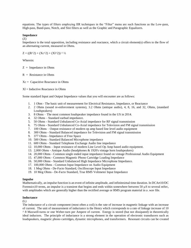
High-pass, Band-pass, Notch, and Slot filters as well as the Graphic and Paragraphic Equalizers.
Impedance
(Z)
Impedance is the total opposition, including resistance and reactance, which a circuit element(s) offers to the flow of
an alternating current, measured in Ohms.
Z = ((R^2) + (Xc^2) + (Xl^2)) ^ ½
Wherein:
Z = Impedance in Ohms
R = Resistance in Ohms
Xc = Capacitive Reactance in Ohms
Xl = Inductive Reactance in Ohms
Some standard Input and Output Impedance values that you will encounter are as follows:
1. 1 Ohm - The basic unit of measurement for Electrical Resistance, Impedance, or Reactance
2. 2 Ohms (sound re-enforcement systems), 3.2 Ohms (antique audio), 4, 8, 16, and 32, Ohms, (standard
Loudspeakers)
3. 8 Ohms – The most common loudspeaker impedance found in the US in 2014.
4. 32 Ohms – Standard earbud impedance.
5. 50 Ohms - Standard Unbalanced Co-Axial impedance for RF signal transmission
6. 75 Ohms - Standard Unbalanced Co-Axial impedance for Television and FM signal transmission
7. 100 Ohms – Output resistance of modern op amp based line level audio equipment
8. 300 Ohms - Standard Balanced impedance for Television and FM signal transmission
9. 377 Ohms - Impedance of Free Space
10. 500 Ohms - Standard Balanced Microphone impedance
11. 600 Ohms - Standard Telephone Exchange Audio line impedance
12. 10,000 Ohms – Input resistance of modern Line Level Op Amp based audio equipment.
13. 2,000 Ohms - Antique Audio (headphones & 1920's vintage horn loudspeakers)
14. 20,000 Ohms - Common single ended input impedance found on vintage Professional Audio Equipment
15. 47,000 Ohms - Common Magnetic Phono Cartridge Loading Impedance
16. 50,000 Ohms - Standard Unbalanced High Impedance Microphone Impedance.
17. 100,000 Ohms - Common Input Impedance on Audio Equipment
18. 1 Meg Ohms - De-Facto Standard, Oscilloscope Input Impedance
19. 10 Meg Ohms - De-Facto Standard, True RMS Voltmeter Input Impedance
Impulse
Mathematically, an impulse function is an event of infinite amplitude, and infinitesimal time duration. In DCArt10/DC
Forensics10 terms, an impulse is a transient that begins and ends within somewhere between 50 S to several mSec,
with amplitudes which are generally higher than the rectified average or RMS program material in a .wav file.
Inductance
(L)
The inductance of a circuit component (most often a coil) is the rate of increase in magnetic linkage with an increase
of current. The unit of measurement of inductance is the Henry which corresponds to a rate of linkage increase of 10
^ 8 Maxwell-turns or one Weber-turn per Ampere of current. Energy is stored (but not dissipated) in theoretically
ideal inductors. The principle of inductance is a strong element in the operation of electronic transducers such as
loudspeakers, magnetic phono cartridges, dynamic microphones, and transformers. Resonant circuits can be created

utilizing a combination of capacitors and inductors. The basic resonant frequency of such a circuit is given by Fr = 1
/ 2 pi (L x C) ^1/2. This principle can be used to create narrow Band-pass and notch filters.
The unit of measurement of inductance = H (Henry)
Note: pi = 3.141592654 (approximately)
.ini files
This is where the initialization constants, factory presets, and user presets were stored by the software the earliest
versions of the software. Because of the 64 Kbytes total .ini file length limitation; a special presets directory is
presently used for this function allowing a much larger number of total presets. The old .ini file extension used to be
found in the Windows directory. DCArt10/DC Forensics10 uses the system registry for all other settings storage.
Instantaneous Sound Recordings
Instantaneous sound recordings are ones in which playback can immediately follow the recording process. The first
sound recording made by Edison was “Instantaneous”. The following is a brief history of this form of recording
technology:
Wax Cylinders (1877 forward)
Aluminum Discs (mid 1920s)
Pre-Grooved Plastic Discs (early 1930s)
Acetate covered Aluminum Discs (mid 1930s)
Acetate covered Glass Discs (early 1940s)
Magnetic Wire (mid 1940s)
Magnetic Analog Tape (late 1940s forward)
Digital Audio Tape (mid 1970s forward)
CD/R’s (early 1990s forward)
.mp3 recorders
Integrator ( ∫ )
An Integrator is a device, system or process which evaluates the area under a curve of one function vs. another. It is
the inverse process of Differentiation (also refer to “Differentiator”). The Diamond Cut Integrator is found as one of
the presets under the Low Pass Filter.
Inter-modulation (Distortion)
Inter-modulation distortion is a very specific type of distortion that results from the amplitude modulating effect which
one frequency has on another in a non-linear system. This form of amplitude modulation results when one frequency
appears as the “carrier” and the other as the “modulating” signal. Since IM distortion is due to non-linearity’s in the
transfer function of a system creating an AM effect, this results in the production of frequency components that are
equal to the sums and differences of integral multiples of the components of the original complex wave. A two-tone
test source is used to measure this parameter, typically consisting of (approximately) a 60 Hz test signal added to a
7,000 Hz test signal feeding the device or system under test. The low frequency signal is applied to the system being
tested with an amplitude value much higher than the upper test frequency, typically by a factor of four or more to one.
Using 60 and 7000 Hz test signals as an example, vestiges are measured at 6,940 and 7,060 Hz and divided by the
value of the 7,000 Hz fundamental in order to determine the level of Inter-modulation Distortion.
Inertia
The property by which matter that is at rest will tend to remain at rest, and matter that is in motion will tend to remain
in motion (in the absence of friction).
I/O
Input / Output refers to the ports into which electronic signals are fed to an electronic device and the ports from which
electronic signals are derived from an electronic device. DCArt10/DC Forensics10 allows you to choose between
several I/O ports, provided you have the sound cards to support the feature.

IPS (Inches per Second) The linear velocity of magnetic tape moving past a recording or playback head is referred to in terms of its IPS (inches
per second) value. For a table of common tape deck speeds, please refer to our Charts, Graphs and Other Useful
Info page.
kHz (kilo Hertz)
The unit used in the measurement of frequency equal to 1000 Hertz. In earlier times, this term was Kilocycles (per
second).
kOhms
The unit used in the measurement of electrical resistance equal to 1000 Ohms.
Latency
Latency is the delay time encountered when operating in Preview mode or in "Live" feed-through mode. Maximizing
the speed of your computer system minimizes latency.
Lateral Cut
A record recording technique in which the groove modulation (undulations) occurs in a side-to-side direction, as
opposed to up and down. This technique was popularized by Emile Berliner with his “Victrola” phonograph.
Launch
Starting a program. This is accomplished by double clicking on the appropriate program Icon (usually found on your
desktop).
Least Significant Bit (LSB)
The smallest quantified increment which an Analog to Digital or Digital to Analog Converter can resolve an analog
Voltage or current. (LSB's are sometimes referred to as "counts.) In DCArt10/DC Forensics10, this value is 1 part in
65,536 (or 1 part in + / - 32,768), for 16 bit system applications. For 24 bit system applications, this value increases
to 1 part in 16,777,216 (or 1 part in + / - 8,388,608). For other sampling depths (values of resolution) use the formulae:
+ / - LSB's = (2^(SD)) / 2
wherein SD = Sample Depth (or resolution) in bits
Limiter
A Limiter is an electronic circuit or system consisting of non-linear elements that will not allow signals above a certain
threshold value to pass through to its output. An upward compressor will produce this effect when its ratio is set to a
high value. The Dynamics Processor can be used as a signal limiter when used in compressor mode when high values
of "ratio" are selected. It also includes “Limiter” presets to make setup easier for the user.
Line Level Signal
A Line Level analog signal is one that develops -10 dBv nominally without clipping and is usually associated with
consumer grade audio equipment input and output ports. This translates into 0.316 Vrms or 0.894 Volts pk-pk (based
on a sine wave). They are usually unbalanced (often using RCA type interconnections).
Note – Pro-level analog signals are often called out in terms of dBu and are at values of +4 dBu which is 1.228 Vrms
or 3.47 Volts pk-pk (based on a sine wave). They are usually balanced (XLR or TRS type interconnections).
Lissajous Figures
When two sine waves are displayed on an X-Y display, with one applied to the X-axis and the other to the Y-axis, the
interacting vectors of the two waveforms are displayed. These waveforms are referred to as Lissajous figures. Signals
having the same frequency but of differing phase (other than 180 degrees) will form elliptical patterns, the phase of
which can be calculated from the intercepts of the waveform with the display axis. This technique if often used to
adjust the azimuth of tape recorder recording and playback heads. A properly aligned tape head will produce no

ellipse, but only a 45-degree line with a positive slope. This can be somewhat compensated for using the Time Offset
feature found in the File Conversions Filter in conjunction with the X-Y plotter found under the View menu.
Loudness
The loudness of a sound is the perceived magnitude due to the auditory sensation produced by an acoustic signal. It
is a function of frequency and signal amplitude. A 50 Hz tone requires sound field intensity 250,000 times larger than
a tone at a reference of 1,000 Hz to achieve the minimal level of perception. The unit of measurement for loudness is
the Sone. See Sone for more details.
Low-pass Filter
A Low-pass Filter is one that attenuates all frequencies that fall above its corner frequency. The degree of attenuation
of a signal outside of the filters pass-band depends on the frequency of interest, the corner frequency, and slope (order)
of the low-pass filter. This type of filter is often used to reduce the hiss on a recording. However, low-pass filters
will also attenuate the "highs" on a recording at the same time, which make them generally undesirable for this
application.
Magnetic Phono Cartridge
A magnetic phono cartridge is a device for converting the mechanical motion of a record stylus into electrical signals
utilizing the properties of magnetic circuits. There are three types of magnetic phono cartridges. They are:
1. Variable Reluctance (early magnetic cartridges)
2. Moving Magnet (the most commonly used)
3. Moving Coil (quite expensive and having costly stylus replacement)*
* The output impedance of moving coil (MC) cartridges are in the 10 to 100 Ohm range. Therefore, they require
special matching transformers or pre-pre-amplifiers in order to be able to drive a conventional magnetic cartridge
input on an audio pre-amplifier.
Mbyte
One million Bytes. (Sometimes 1024 kBytes for disks)
Median
The median value of a series of numbers is the number that resides in the center of the sorted string. For example, in
the series of numbers 2, 4, 7, 3, 8, 0, 7, 1, 9, the median value is 4. (Sort = 0,1,2,3, 4 ,7,7,8,9)
Microphone
A microphone is a device (or transducer) that converts acoustical signals to electrical signals. There are many variants.
In order of development starting with the earliest they are as follows: Dynamic (Bell Telephone), Carbon Button
(Edison), Condenser, Ribbon (a special form of a Dynamic type), Piezoelectric, and Electret (a special form of a
Condenser type). Any of these technologies can be created with various polar pickup patterns (such as omni-
directional, cardioid, unidirectional and others).
Milliseconds
The unit used in the measurement of time equal to 1/1000 of a second.
Mils
The unit used in the measurement of distance equal to 1/1000 of an inch. The diameter of phonograph styli are
generally specified in "mils". (If the stylus is elliptical in shape, the larger of the two dimensions is generally given.)
Modulation
An electronic process in which one source modifies the characteristics of another signal source. For example, an audio
signal may be used to Amplitude, Frequency, or Phase Modulate a sine wave signal (called a carrier). The result
would be an Amplitude Modulated carrier in the first case (AM). In the second case, the result would be a Frequency
Modulated carrier (FM). In the last case, the result would be a Phase Modulation (PM) carrier. These are techniques

used for transmitting radio, television, and data. Sometimes, in audio, one refers to the undulations on a record as
record groove "modulation".
Monophonic
An audio signal or a .wav file that contains only one unique channel of aural information is sometimes referred to as
being monophonic.
Mu (μ)
The small signal amplification factor that a device exhibits in a circuit, often associated with Electron Tubes (and
Junction Field Effect Transistors or MOSFETs).
Voltage Amplification = μ x Rl / (Rl + Rp)
Where u (mu) = Tube Amplification Factor
Rl = Plate Load Resistance in Ohms
Rp = Plate Resistance in Ohms
Mu-law (μ-law) Compression
This is a form of data compression primarily used in telephonic applications. It takes advantage of the logarithmic
nature of the sense of human hearing to accomplish its task effectively. It compresses a 16-bit signal into 8 bits using
logarithmic signal mapping, producing a 2:1 compression ratio while maintaining 13 bits of dynamic range. The
bottom 3 LBS’s of precision are dropped. Typically, this is used in 8 kHz Monophonic formats. DCArt10 supports
this format.
Multi-path Distortion
Multi-path distortion is a phenomenon that can occur during FM broadcast reception. It occurs when the receiving
antennae picks up two (or more) signals from the same transmitter. This dual pickup consists of the direct signal from
the transmitter (usually a line of sight trajectory) and a second parasitic signal arriving at the antenna some time later.
The second signal is a reflected signal off of a mountain, building or other object, and arrives at the antennae sometime
after the main signal had arrived. The time shift between the main signal and the reflected signal creates phase
distortion of the de-modulated audio signal when these two signal mix together. This phase distortion manifests itself
in the last two octaves of the audio spectrum and sounds like "slurring" of the pronunciation of the letter "s" and
general harshness. It will sound worse on a stereo broadcast than on a monophonic one. There are several cures for
this problem. Purchase a directional antennae (one with a high front to back ratio) and install it as high as possible,
aiming it towards the transmitter of interest. Secondarily, you can minimize the problem by switching over to
monophonic during a particularly distorted broadcast. And lastly, when all else fails, you can reduce the distortion by
utilizing the "de-esser" found in the Dynamics Processor or apply one of the appropriate presets found in the Diamond
Cut Channel Blender effect.
Multiple Notch Filter
This is the term used in the DCArt10/DC Forensics10 program used to describe a comb filter. A comb filter is a wave
reject filter whose frequency rejection spectrum consists of a number of equidistant elements resembling the tines of
a comb. This filter is useful for getting rid of "Hum" type noise containing more than just the line frequency
fundamental component. This type of noise is line frequency related noise and sometimes described as "Buzz." This
results from the interaction of non-linear systems with the finite output impedance presented by the power line sine
wave Voltage waveform, adding harmonics to the same. Buzz can also be introduced into and audio system through
non-sinusoidal current waveforms producing "H" fields which couple into noise sensitive loop areas (or ground loops)
in audio systems. The Diamond Cut Harmonic reject filter is one example of a Multiple Notch filter.
Musical Scale
There are two relatively common musical scales. They are the “Scale of Just Intonation”, and the “Scale of Equal
Temperament”. The Scale of Just Intonation requires at least 30 discrete frequencies for each octave, making it
relatively impractical to build musical instruments with fixed tones to play in the Just Scale. Therefore, the scale of
Equal Temperament containing only 12 notes per octave is the one in general use.
For a chart which displays the frequencies of four octaves of the tempered scale, simply turn to our Charts, Graphs,
and Other Useful Info section.

NAB Equalization Curve
(National Association of Broadcasters)
The NAB Curve is a set of equalization frequency response contours, which are used by manufacturers of analog tape
recorders to compensate for the inductive nature of a tape head. The equalization time constants specified depend on
tape speed. One pair of time constants are specified for 1 7/8 ips (inches per second) and 3 3/4 ips. Another pair of
time constants are specified for 7 1/2 ips and 15 ips. The low frequency breakpoint for all speeds is 50 Hz. The high
frequency breakpoint for 1 7/8 and 3 3/4 ips is specified as 1770 Hz. The high frequency breakpoint for 7 1/2 and 15
ips is specified as 3180 Hz. These curves can be found as presets within the Diamond Cut Paragraphic Equalizer.
Additional curves can be found on the presets sharing section of the Diamond Cut User’s forum.
Neper (Napier) (Np)
Nepers are units of ratios of measurement like the dB, except using base e (~2.71828183) rather than base 10. For
details, please refer to “dB” in this glossary. To convert between Nepers and dB, use the following relationships:
1 Np = dB x 0.115129255
or
1 dB = Np x 8.685889638
Noise
Noise are unwanted disturbances superimposed upon a useful signal that tends to obscure its information content.
Also, refer to Signal-to-Noise ratio for more information.
Noise Gate
A noise gate is an electronic device, which turns off a signal path when an input signal is below a predetermined
threshold value. The Dynamics Processor produces a noise gate effect when you check the Expander/Gate function.
You must set the ratio to the highest number for the best noise gate effect.
Notch Distortion (crossover distortion)
A discontinuity in a signal waveform sometimes produced by power amplifiers is referred to as “Notch Distortion”.
It is always found in class B Amplifiers and sometimes found in inadequately biased class AB Amplifiers. It is usually
associated with audio power amplifiers. High levels of “Notch” distortion results in a raspy sound at low signal output
levels.
Notch Filter
A notch filter is one which attenuates all frequencies close to the center frequency of the filter setting. The degree of
attenuation and the range of frequencies which are attenuated by this filter are determined by the filters Q or bandwidth.
This type of filter is often used to minimize hum or acoustic feedback from a recording. This type of filter is sometimes
referred to as a "band reject filter."
Octave
An octave is a group of eight musical notes and also a doubling of frequency. For example, the range of frequencies
from 440 Hz to 880 Hz is 1 octave. The next octave will end at 1,760 Hz. Note that in two octaves, the frequency has
increased by a factor of four.
Offset
A fixed or DC value of Voltage or current added into a circuit to shift the quiescent operating point of a device or
display. Offset is used in DCArt10/DC Forensics10 to allow small features to be seen in a signal when the detail
exists towards the top or bottom of the signal workspace display area. DC offset can be removed from a .wav file by
applying the high pass filter set to 10 Hz, Butterworth response, and 6 dB/octave.

Ohm (Ω)
(R) (or the Greek Letter Omega )
The Ohm is a unit of electrical resistance in which a potential difference in a circuit of 1 Volt produces a current flow
of 1 Ampere.
Ohms Law
V = I x R
wherein:
V = Voltage in Volts,
I = current in Amperes,
R = resistance (in Ohms)
Over-modulation
When an audio signal is applied to an audio device, which is greater than the device can handle in a linear transfer
manner, this creates a condition of "over-modulation". It results in a distorted sound in the output of the device being
over modulated. Sometimes, this condition is referred to as "clipping," meaning that the amplification devices of an
electronic system are either cutting-off or saturating due to overdrive.
Overtones
Overtones are multiples of a fundamental frequency. The Diamond Cut Overtone Synthesizer is capable of creating
signals of this type (even multiples) at the upper end of the audio spectrum (above 6000 Hz). The Virtual Valve
Amplifier (and its Exciter) are also capable of creating overtones (odds and evens) referenced to various fundamental
frequencies.
Paragraphic Equalizer
This is a Diamond Cut invention in which a parametric equalizer is coupled to a graphic display of its transfer
characteristic. It yields the best of both worlds produced by a graphic EQ and a parametric EQ.
Parametric Equalizer
A variable electronic filter in which the following three parameters may be adjusted on each parametric channel:
1. Frequency
2. Level (attenuation or amplification)
3. Bandwidth
Parametric equalizers are usually equipped with several parametric channels, which can all be used simultaneously or
each one can be individually bypassed. DCArt10/DC Forensics10 includes a 10 band Paragraphic equalizer, which is
a combination of a parametric and a graphic equalizer.
Pathé
Pathé Freres Phonograph Company was a European based record and phonograph company, who utilized a somewhat
unique groove modulation technique. Their method produced a vertical stylus displacement (like Edison Hill and
Dale Diamond Discs and Cylinders) however; this was accomplished by a different mechanism. The groove on these
recordings is "width" modulated, and so when a conical stylus interacts with these groove width modulations, a vertical
displacement is thereby produced. If you are transferring a Pathé 78 rpm recording with a stereophonic pickup
cartridge, you will need to use the DCArt10/DC Forensics10 Mono (L - R) file conversion algorithm.
Pentode
A Pentode is an electron tube (or valve) containing five elements. They include a cathode, anode, control grid, screen
grid and a suppressor grid (or beam deflector electrode which replaces the suppressor grid in beam power pentode
configurations). They are most commonly used in audio power amplifiers, but are sometimes found in microphone
pre-amplifiers. Typical beam power pentodes listed in ascending power levels include types 6BQ5/EL84, 6L6GC,
5881, 7591, KT-66, 6CA7/EL34, KT-88, and 6550. Some pentode tube types are available in the Diamond Cut Virtual
Valve Amplifier (VVA).
Phantom Microphone Power
(Sometimes referred to as P48)
High performance microphones (such as large diaphragm condenser types) require an external source of power to
drive their internal circuitry. The Voltage of this power source is generally between 12 to 48 VDC (most commonly
48 VDC). The negative side of this power source is connected to pin 1 (the shield side) of a 3 pin XLR style connector.
The positive side of this source is connected (via two ~ 6800 Ω resistors) to pins 2 and 3 on the connector with one
resistor located in series with each leg at the source end.
Phase Inversion
Phase inversion is the phenomena that occurs when one of two signals has become 180 degrees phase shifted with
respect to the other. This sometimes accidentally occurrs on vinyl stereo recordings because the input leads to one of
the two cutting lathe driver heads became "swapped" in location. This can be corrected by using the File Converter,
using the Left or Right Phase-Invert feature.
Phon
The Phon is a measurement of the perceived loudness of a sound which takes into account the non-flat frequency
response of the human sense of hearing. The perceived loudness of a sound in Phons is equal to the sound intensity
in dBs of an equally loud 1 kHz pure tone signal; 1 dB SPL @ 1 kHz = 1 Phon. Also, refer to the glossary topic
“Fletcher-Munson Loudness Contours”.
Pi (π)
Pi (Greek Letter) is the symbol that relates the ratio of the circumference to the diameter of a circle.
π = C / D
wherein:
C = Circumference of a Circle
D = Diameter of a Circle
π =
3.1415926535897932384626433832795029
(Approximately because it is an irrational non-repeating number.)
Pink Noise
Pink Noise is random noise, which is characterized as containing equal energy per unit octave. When viewed on an
octave based spectrum analyzer, it will produce a flat horizontal line on the display. Pink Noise is useful for
characterizing the frequency response of electronic systems and for analyzing room acoustic transmittance and
resonance. Pink noise can be created through a two-step process using DCArt10 or DC Forensics10. First, create
white (random) noise with the Makes Waves generator function. Next, process the signal through the Multifilter
using the factory preset labeled "White to Pink noise converter, 20 kHz." You can also convert Pink Noise to White
Noise by applying the Multifilter preset called “Pink to White Noise Converter” to a Pink Noise File.
.pkf files
These are "peak files" (.pkf) which represent the .wav files for display purposes in the source and destination windows.
They are a small subset of the .wav file consisting of one sample for every 200 .wav file samples. The data point
selected is the peak value of the .wav file found within that 200 sample window. Each .wav file is stored with an
attendant .pkf file that is created by the software at the time when the file is recorded or modified or when the "rebuild
peak file" command is used.

Potentiometer
A potentiometer is a three-terminal passive electronic device consisting of a resistance element and a wiper arm. They
can be of the slider type or the rotary type and come in various resistance tapers. They produce a variable Voltage
Divider effect on a signal in a circuit. They are used in the analog portions of audio circuits to vary the gain of a
particular circuit. The most common application of this component is as a Volume Control, but they are also found
in Graphic Equalizers and other analog signal processing systems. The term “Pot it up” comes from this component.
Pot it up is an early radio term for “turn it up” or “make it louder”.
Power
Power is the time rate for the transfer of energy in any system. In other words, Power = Energy / time. In electrical
terms, power is given in Watts and has the following relationships to Voltage, Current, and Resistance:
P = V x I (Cos θ)
wherein:
P = Power in Watts
V = Voltage in Volts
I = Current in Amperes
θ = the displacement (phase) angle between the Voltage and Current Waveforms (assuming that they are both sine
waves)
also (for purely resistive situations),
P = (I ^ 2) R
and
P = (E ^2) / R
wherein:
R = Resistance in Ohms
Power Amplifier
(Power Amp)
A power amplifier is a device that provides power amplification of an audio signal. Generally, this is the device that
is used to drive a loudspeaker, the cutting head of a record lathe, or an audio transmission line, and is the final stage
of amplification in an audio system. Audio power amplifiers generally develop somewhere between 10 to 1000 Watts
of output power, depending on make and model (although shake table audio amplifiers and AM radio transmitter
modulators can be found which produce well over 50,000 Watts).
To minimize power loss in the transmission process, and to maximize the systems dampening factor, it is important
to minimize Voltage drops across loudspeaker distribution cables. Poor (low) dampening factor can produce an ill-
defined (or resonant) bottom-end (bass). Long distances between your power amplifier and your speaker system will
require larger diameter cables. To determine the correct cable for your application, refer to the Wire Table provided
in the Charts, Graphs and Other Info section of this User’s Guide.
Power Cepstrum
See “Cepstrum”
Pre-Amplifier
(Pre-amp)

A Preamplifier is a device that provides Voltage amplification of an audio signal. Sometimes these devices also
include equalization networks and/or tone (bass, treble, loudness, etc.) controls. Pre-Amplifiers generally produce
about 100 milliwatts (mW) of output power and require a power amplifier connected in cascade in order to be useful
for driving loudspeakers or very long audio transmission lines.
Pre-Emphasis
Pre-emphasis is the intentional added amplification which is sometimes applied to the top end of the audio spectrum
during a recording or radio transmission process in order to raise the signal level at high frequencies substantially
above the noise (hiss) level of the system. This process is reversed during the reproduction process of the signal in
order to recreate an overall flat frequency response. The result of this process is an improvement in the signal-to-
noise ratio of the system. For example, the third specified time constant of 75 Sec associated with the RIAA
equalization curve is pre-emphasis. Also, FM broadcast transmission utilizes a 75 Sec (or sometimes a 25 Sec)
pre-emphasis to improve its signal-to-noise ratio. This process is reversed at your receiver (de-emphasis). The
Paragraphic equalizer contains 75 Sec pre-emphasis and de-emphasis preset curves.
Presets
Most of the Diamond Cut filters and effects have a plethora of descriptive presets. Usually, the most efficient place
to start when using a particular filter or effect would involve selecting one of the factory presets, and then tweaking
the parameters to fine tune the system to your own personal taste. If you desire to keep a separate copy of your presets
on external media, they can be found in the Diamond Cut directory under this pathways: * \DCForensics10Presets
Pure Tones (as related to Noise Laws)
A pure tone occurs when the noise level in any one Octave weighted frequency band exceeds those in an adjacent
frequency band by 3 dB or more. The High Precision Analyzer found in the DC Forensics version has the
characteristics needed to evaluate compliance with the various state and federal laws in this regard when used in
conjunction with a calibrated / certified / NIST traceable microphone.
Q
(Quality Factor of Resonant Systems)
Q is the ratio of the reactance of a system (or filter) to its resistance (or losses). Q determines the systems bandpass
width. Higher “Q” values producing sharper (narrower and more selective) responses.
Q = Reactance (@ system resonance) / Resistance.
Quefrency
Quefrency is the unit of measure associated with the horizontal (X) axis of a complex ceptstum graph. The units are
not frequency or time in the standard sense of those terms. Rather it is the ratio of the sample rate divided by the
number of samples that a peak persists. For example, if a signal persists for 50 samples and is sampled at 48,000
samples per second system, its quefrency will be 48000 / 50 = 960 Hz.
Quiescent Point
The Quiescent Point (or operating point) of an amplification device like an electron tube or a transistor, refers to the
bias established on its linear portion of the transfer function curve when the device is "at rest" (i.e. no signal input
applied). For example, the Virtual Valve Amplifier allows you to adjust the Quiescent (operating) point of Class A
amplifiers anywhere from near cutoff to near saturation.
RAM (Random Access Memory) RAM is a digital electronic device for storing binary information temporarily. RAM performance is generally
characterized in terms of its size in Mbytes, and its access time in nanoseconds. Your computer will need a minimum
of 2 GBytes of RAM to run the DCArt10/DC Forensics10 application correctly.
Real Time
A system that can process a signal and output the signal at the same rate at which it is being fed into the system is said
to be a real-time processor. The DCArt10/DC Forensics10 algorithms can process signals in real-time or faster
provided your platform is a 500 MHz Intel Pentium or higher.

Real Time Analyzer (RTA)
A Real Time Analyzer is a form of spectrum analyzer used for the analysis of audio signals. Unlike conventional
spectrum analyzers, it does not use a single filter in a scanning mode to produce an Amplitude vs. Frequency display,
which is a relatively slow process. Instead, it processes audio signals in parallel, so that all frequency bands are
displayed simultaneously. Generally, RTA's have 31 bands (in 1 / 3 octave increments) covering the frequency
spectrum from 20 Hz to 20 kHz. They usually come with a calibrated electret microphone and a built-in pink noise
generator for making acoustical measurements. Your Diamond Cut Spectrum Analyzer has 1/3rd Octave-based RTA
capability.
Rectified Voltage
This is a process wherein an alternating current signal is converted into a direct current, amplitude modulated envelope
representation of the source signal. Often, some smoothing is applied to this signal with a set of time constants referred
to as "attack" and "release". This signal is used in such devices as dynamic filters, companders, compressors,
expanders, spectral enhancers, etc. and is digitally simulated in some of the DCArt10/DC Forensics10 algorithms.
Residue
The residue of a filtered signal is the algebraic difference between the filter output and its signal input. DCArt10/DC
Forensics10 allows you to hear the "residue" of two of its filters by enabling the "Keep Residue" function. Several
filters that include this feature are the Continuous Noise Filter and the Harmonic Reject Filter. This feature has been
included because in some cases, it may be useful as an aid to hear what you are filtering out of the signal source. This
is particularly useful when adjusting the Harmonic Reject Filter when attempting to remove "Hum" or "Buzz" from a
recording.
Resistor (Resistance)
(R)
(Ohms) ( )
A resistor is a basic electrical device that has electrical resistance, and is used to control the amount of current that
flows in a circuit. The unit of measurement for a resistor is the Ohm.
R = E / I
wherein:
R = Resistance in Ohms
E = Voltage in Volts
and
I = Current in Amperes
Resonance (Electrical)
Resonance occurs in a system in which two elements are operated in quadrature (each element operating at ¼ the
signals period) to produce a minimization or maximization of said signal.
Fr = 1/2 π (L x C)^1/2
wherein:
Fr = Resonant Frequency in Hertz (Hz)
L = Inductance in Henries
C = Capacitance in Farads

Resolution
Resolution is the minimum amplitude increment into which the A-D converter of a discrete time system can divide an
analog signal. The resolution of DCArt10/DC Forensics10 is usually 16 bits, which is 1 part in 65,536. However,
with the appropriate sound card, DCArt10/DC Forensics10 does support up to 24-bit I/O resolution. Resolution can
also refer to the minimum "time slice" into which a sampled data system is divided or displayed.
Reverse RIAA Curve
DCArt10/DC Forensics10 is equipped with a family of reverse RIAA curves, allowing you to use a standard RIAA
phonograph pre-amplifier to perform your mastering of old acoustical and 78-RPM recordings. A straight reverse
RIAA curve is supplied for acoustical recordings, and a number of reverse RIAA curves with varying values of
turnover frequency are supplied for electrically recorded 78s. These reverse curves can be found as several of the
Paragraphic equalizer factory presets. An RIAA curve encoded recording can also be decoded using the Diamond
Cut Virtual Phono Preamp.
Reverberation
The process whereby the acoustical reflections of a room or concert hall are reproduced artificially, with devices such
as tapped delay lines working in conjunction with mixing and phase shifting devices or algorithms.
RIAA
Equalization Curve (Record Industry Association of America)
The RIAA Curve is a non-linear frequency response contour which was utilized by some manufacturers of LP records
after around 1950 and was made pretty much the industry standard by 1955. It’s purpose was to improve the S/N of
the disc recordings. It specifies three R*C time constants to be used by playback pre-amplifiers in order to reverse
the record cutter equalization. The three time constants and their corresponding breakpoint frequencies are as follows:
1. 3180 uS (50 Hz) (shelf or pullout frequency)
2. 318 uS (500 Hz) (turnover frequency)
3. 75 uS (2120 Hz) (roll-off frequency)
This curve can be de-coded using the Diamond Cut Virtual Phono Preamp if you are using a flat hardware preamplifier.
RIAA / IEC Equalization Curve
The RIAA / IEC equalization curve is defined in terms of the same time constants as the RIAA curve, with one
additional time constant added of 7960 S. This provides 3 dB of attenuation at 20 Hz rolling off at -6 dB / Octave
thereafter. Below is a listing of all of the time constants associated with the RIAA / IEC Equalization Curve:
1. 7960 S (20 Hz) (low
frequency roll-off)
2. 3180 S (50 Hz) (pull-out
frequency)
3. 318 S (500 Hz) (turnover
frequency)
4. 75 S (2120 Hz) (roll-off frequency)
Right Mouse Button
DCArt10/DC Forensics10 implements the following six functions with the right mouse button:
1. Play From Here
2. Preview From Here
3. Copy
4. Cut
5. Paste Over
6. Paste Insert
7. Mute
8. Zoom-In

9. Zoom-Out
10. Zoom-Out Full
11. Add a Marker
12. Label a Marker
13. Delete a Marker
14. Clear All Markers in Selected Area
15. Undo Last Edit
16. Select All
17. Snap Selection to Zero Crossing (Q)
Note: A pop-up menu will appear when using the right mouse button containing the above-mentioned items that you
can select from when they are active. Items that are not active will be grayed out.
RMS (Root Mean Squared)
RMS is the square root of the average of the squared instantaneous values of a waveform taken over the waveforms
time duration (sometimes referred to as the "effective" value or the "heating" effect value). In electrical terms, a.c.
Voltages and Currents can be described in terms of their RMS value; in acoustical terms, sound pressure
(acoustomotive force) can be described in terms of its RMS value.
Roll-off
In the record industry, roll-off usually refers to the amount of attenuation in dB @ 10 kHz which must be applied
during record playback in order to achieve a flat response on the high end of the audio spectrum. It is a form of de-
emphasis. For example, the roll-off for the RIAA curve is –13.7 dB and –12 dB for the AES curve.
Roll-off Frequency
For a Low-pass filter or for an equalization curve (such as the RIAA curve), the upper cutoff frequency is sometimes
referred to as the Roll-off Frequency.
RPM (Revolutions Per Minute)
Some common record speeds are 33.33 RPM for LPs, 45 RPM for records with the same name, 78.26* RPM for most
so called electrically recorded lateral 78s (like Victor), 78.8 RPM for Edison Lateral's, 80 RPM for Edison Diamond
Discs, and 160 RPM for most Edison Cylinder recordings. Additional speeds such as 16.66 RPM will occasionally
be encountered. A comprehensive listing of record speeds can be found in the Charts, Graphs, and Other Useful Info
section of this User’s Guide.
Rumble
Rumble is a low frequency noise signal, typically below 50 Hz, which is often found on records. This phenomenon
can be caused by seismic effects during the mastering process or during playback. On low quality or worn turntables
or cutting lathes, it can also be produced by irregularities in the main thrust-bearing race. To attenuate turntable
rumble using DCArt10/DC Forensics10, use the High-pass Filter. Start with settings of 30 Hz and 18 dB / Octave
(or steeper), and adjust the frequency upwards or downwards until you are satisfied with the results. Acoustical
recordings will benefit from settings as high as 125 Hz, depending on the material.
Sample Rate
The rate at which an analog signal is converted to discrete numbers by an A-D converter. For audio systems, sample
rate is expressed in kHz. DCArt10/DC Forensics10 supports any number of standard sample rates including:
1. 11.025 kHz
2. 22.05 kHz
3. 44.1 kHz
4. 48.00 kHz
5. 88.2 kHz
6. 96.00 kHz
7. 192.00 kHz
8. Your entered choice of a numerical value from 100 Hz up to 210.00 kHz*

*If your sound card supports intermediate sampling rates, you can also enter the numeric value of any sample rate you
desire, between 100 Hz (0.1 kHz) to 192 kHz for recording purposes.
Sampling Theorem
In a sampled data system (like the environment in which your DCArt10/DC Forensics10 program is operating),
sampling theorem tells us that regularly spaced sampling must occur at least at the Nyquist rate, which is twice the
frequency of the highest frequency signal or noise component that is expected to be resolvable by the system (without
aliases). In other words, in a system expected to exhibit a frequency response up to 20 kHz, the minimum sample rate
will have to be 40 kHz. Because it is impossible to construct an ideal Low-pass filter, the sampling rate will have to
be somewhat larger than 2X the desired maximum frequency response value. In practice, a 44.1 kHz sampling rate
is generally used in 20 kHz frequency response audio applications (although sometimes 48 kHz and 96 kHz are also
used).
Shielded Cables
Shielded cables are special cables which are designed to minimize stray noise fields (particularly E fields) from
entering an audio system through the interconnection wiring from component to component due to extraneous sources.
Most often shielded cables are of the co-axial type so that loop area is also minimized, resulting in a minimization of
"H" field pickup. However, some systems use a balanced pair of shielded wires which further minimizes pickup,
provided the appropriate terminating transformers or differential amplifiers & line drivers are used on each end of the
cable.
SID
Slewing-Induced Inter-modulation Distortion. This is similar to TIM. See TIM for details.
Signal-to-Noise Ratio
The ratio of signal-to-noise (Voltage, current, or acoustical sound pressure level) that is expressed in dB. Signal-to-
Noise ratio in dB = 20 log (signal / noise).
SINAD (Signal, Noise And Distortion)
Essentially, SINAD is the reciprocal value of a THD measurement and is expressed in dB.
SINAD = 20 log(signal rms value + noise & distortion) / (rms value of noise & distortion)
Single-Ended Noise Reduction
Single-Ended Noise Reduction are the processes wherein noise is removed from an un-encoded audio signal.
Algorithms like the Impulse, Continuous, Dynamic, Harmonic Reject, and Notch filters are examples of Single-Ended
Noise Reduction tools.
Slew Rate
Slew rate is the maximum dv / dt (and sometimes the maximum di / dt) that an audio system component can react to.
Parasitic Miller capacitances in operational amplifiers are generally the cause of this parametric limitation (collector
to base or drain to gate in the case of transistors). When an audio component is confronted by a signal exceeding its
maximum slew rate capability, the system reverts to slew rate-limited mode of operation. During this time interval,
all audio information is lost resulting in severe distortion of the applied input signal.
Slope
In the context of DCArt10/DC Forensics10 and audio filter terminology, slope is the linear rate of change of amplitude
vs. frequency of a filter past its corner frequency. This is expressed in dB / Octave or dB / Decade. 6 dB / Octave =
20 dB / Decade, 12 dB / Octave = 40 dB / Decade, etc.
Slot Filter
A slot filter is the compliment to the "notch" filter. It is a variable narrow Band-pass filter; capable of greater
selectivity than a typical Band-pass filter. It is often used in Forensics work for isolating particular sounds like the
ringing of a telephone on a recording in a crowded noisy bar situation, or anything similar. By allowing only a very
narrow "slot" of frequencies through the system, one can observe the "slotted-band" with a much improved signal to
noise ratio compared to the wideband signal. The DCArt10/DC Forensics10 slot filter can be found under the Notch

filter and is activated by checking the appropriate box. Multiple slot filters can be run via the Multi-Filter. If the slots
that are desired are harmonically related, you could use the Harmonic reject filter in "keep-residue" mode to produce
up to 500 slots in one pass.
Sone
A Sone is a unit of measurement for sound loudness. A simple tone of a frequency of 1 kHz and at a level 40 decibels
above a listener's threshold of perception represents a loudness of 1 Sone. A loudness of any sound which is judged
by a listener to be “n” times greater than that of the 1 Sone tone is defined as “n” Sones.
Sound Level
Sound Level is a weighted sound pressure level obtained by the use of a metering system and any of three weighting
standards as established in the American National Standard Specification for General Purpose Sound Level Meters.
The reference pressure is 2 X 10 ^ -5 Newton per meter ^2. The two most common standards are the "A" and the "C"
weighting factors. The "A" weighting characteristic responds mostly to frequencies in the area of the greatest
sensitivity of the human ear in the 500 to 10,000 Hz range. The "C" weighting characteristic is nearly uniform over
most of the audio spectrum. The 0 dB reference sound pressure level (SPL) for a sound level meter is 0.0002 microbars
using a simple tone of 1000 Hz.
For a chart showing several common sound sources and their Acoustic Power and Sound Power levels (from 10 meters
distance to the source), simply turn to the Charts, Graphs, and Other Useful Info section.
Sound Wave Velocity
Sound Wave Velocity in air as a function of temperature is given by the following:
c = 33,100 (1 + 0.00366t)^1/2
wherein:
c = Sound Wave Velocity in air in centimeters per second
and
t = temperature in degrees centigrade
Therefore at 70 degrees C, sound will travel at 37,098.6 centimeters per second, or around 830 miles per hour.
Sound Wavelength
The Wavelength of a sound wave is given by the following equation:
λ = c / f
wherein:
λ (lambda) = wavelength in centimeters
and
c = Sound Wave Velocity
and
f = frequency in Hz (cycles per second)
S/PDIF
S/PDIF (Sony / Philips Digital Interface Format) is a serial digital signal format used to connect digital audio devices
together. It is a subset of the IEC 60958 (or AES/EBU) standard. It is electrically characterized as a coaxial system
terminated with 75 Ohms on each end and typically using RCA (orange in color) or BNC connectors.
Speech Filter
A filter which typically has a Band-pass only between the frequencies of 300 Hz to 3 kHz, and which is used to
improve the basic intelligibility of speech. Often, this type of filter uses slopes of -12 dB / Octave. This characteristic
can be replicated with the Diamond Cut IIR based Band-pass filter. An alternative speech filter that is sometimes
useful is called the Steep Slope Speech filter. Its response is 250 Hz to 3.5 kHz with a slope of 18 dB / Octave.
Speed
See RPM
Spectrogram
A Spectrogram is a system for presenting audio data in a graphical form and is a special case of a spectrum analyzer
coupled to an oscilloscope. The horizontal (X) axis represents time, the vertical (Y) axis plots frequency and the gray
scale brightness (or color) (Z axis) represents the signal intensity. Audio Spectrograms are used forensically for
spectrographic voice recognition (sometimes referred to as voiceprints) and acoustical analysis applications. The
software includes a Spectrogram feature, which is found under the Forensics menu.
Spectrum
Spectrum is band or range of frequencies as in the audio spectrum, the light spectrum, or the electromagnetic spectrum.
Spectrum Analyzer
A spectrum analyzer is a device for analyzing and displaying the Amplitude versus Frequency characteristic of a
portion of a spectrum. They fall into two general categories:
1. Swept Band-pass Filter (a serial process of analysis).
2. Real Time Analyzer (a parallel process of analysis).
Spectral Enhancer
An electronic device or system which is used to expand the dynamic range of the upper and/or the lower octaves of
the audio frequency spectrum, leaving the mid-band portion of the spectrum unprocessed. This has the effect of
increasing the "definition" of a recording without continuously amplifying hiss and rumble which may be present on
the source material. It is a form of dynamic filter which uses the principle of "upward expansion" to improve dynamic
range. The Diamond Cut Dynamic Noise Filter contains a Spectral Enhancer mode of operation, which can be enabled.
Spectral Subtraction
Spectral subtraction is a method for reducing the unwanted noises associated with a recording using the amplitude
elements of the frequency domain information contained in a .wav file. A noise fingerprint is taken, and this frequency
domain information is then subtracted from the rest of the file and then re-converted back to the time domain. This
technique is primarily used in forensics audio applications, and can be found as one of the CNF Mode options in the
Continuous Noise filter.
Stroboscope A stroboscope is a device which indicates the RPM speed of a turntable by creating an optical illusion of the slowing-
down, freezing, or speeding-up of a pattern when illuminated by a pulsating light source operating at a known
frequency. You can create your own stroboscope disc by dividing a circle evenly into black and white segments. Use
the following formulae to calculate the number of segments required per 360 degrees (1 rotation of the disc) into
which the disc must be marked:
60 Hz power systems: # of segments = 7,200 / RPM*
50 Hz power systems: # of segments = 6,000 / RPM*

For example, assume that you want to construct a strobe for use in the United States where the power system operates
at 60 Hz in frequency. We want to design it "to freeze" at 78.2 RPM. 7,200 / 78.2 = 92.07.Round the number to 92
segments. Divide your circle into 92 evenly spaced segments, and voila, you have your strobe. Because of the
rounding error, the strobe you constructed will be in error by 0.08 %. Your strobe will have to be used under a
fluorescent or neon light connected to the power line in order to function. Incandescent lamps will not work because
of the long thermal time constant of their filaments.
For a chart that will help you create your own strobe using common line frequencies and RPM values, go to our
Charts, Graphs, and Other Useful Info section.
Note: DCArt10/DC Forensics10 provides two bitmaps that you can print and use as phonograph strobes covering the
important speeds. These can be found in the Diamond Cut Directory at “Strobe50Hz.wmf” and “Strobe60Hz.wmf”.
Sub-harmonics
Sub-harmonics are fractional multiples of a fundamental frequency. The Diamond Cut Sub-harmonic synthesizer is
capable of creating certain signals of this nature in the bass end (below 75 Hz) of the audio spectrum.
Square Wave
A square wave is a signal consisting of a fundamental frequency and the sum of all of the odd harmonic components
of that fundamental frequency on the spectrum up to an infinite number of harmonics. An ideal square wave contains
approximately 43% Total Harmonic Distortion (THD).
Styli
Styli are the devices used to transmit the mechanical undulations of a phonograph recording to its pickup or reproducer.
Early styli were made from cactus needles or steel. Later, Osmium (osmiridium), Sapphire and Diamond became the
norm for phonographic styli use. A chart of styli (sizes and shapes) for various record types can be found under the
Charts, Graphs, and Other Useful Info section of this User’s Manual.
Tape Head
A tape head is an electromagnetic device used in a tape recorder to apply and read magnetic signals onto (and from)
magnetic tape media. It consists of a coil mounted on a magnetic structure having a “gap” where the tape comes in
contact. The tape head gap width in conjunction with the magnetic particle size on the tape media determines the
frequency response of the system. This process follows Faradays Law of electromagnetic induction:
Vhead = - N dø / dt
wherein
Vhead = Tape Head Voltage
N = Number of turns of wire on the tape head structure
dø / dt = The time derivative of magnetic flux
Since dø / dt is proportional to and increases with frequency, this tape head Voltage signal increases at a rate of 6 dB
/ Octave and must be compensated for to prevent tape saturation. The process to provide this compensation is called
tape equalization.
Tape Head Gap
The Tape head gap is the discontinuity in the magnetic pathway (or circuit) formed in the tape head structure which
runs perpendicular the direction of the tape movement. Ideally, the playback head gap should be smaller than one half
the Lambda (or wavelength as it relates to the speed of the tape) of the highest frequency signal to be recorded. The
following is a listing of typical Tape Head Gaps by Tape Head type:
Playback Heads: 1 to 5 microns (micro-meters)
Recording Heads: 3 to 13 microns (micro-meters)
Erasure Heads: 25 to 150 microns (micro-meters)

Tape Recorder Speeds
See IPS
THD (Total Harmonic Distortion)
THD is a figure of merit as to how much non-linearity a system is imposing upon an audio conduit. The Spectrum
Analyzer has the ability to measure the THD of an item under test when used in conjunction with either the Make
Waves generator or an external hardware equivalent. %THD = Amplitude of the Harmonic Content of a signal /
Amplitude of the Fundamental Component. When using hardware to make this measurement on very low distortion
equipment, it is necessary to account for the Generator THD. Therefore, one must measure the test Generators THD
at each test frequency as well as the System Measured THD (of the whole system). Then, one must apply the following
equation:
Actual THD = (((System Measured THD)^2 – (Generator THD)^2))^1/2
THD + N (Total Harmonic Distortion plus Noise)
This is what is actually measured by most THD meters, including not only the harmonic distortion created by the
device being tested, but its noise as well.
Thermal Noise (Floor)
Any electrical conductor produces a random noise Voltage as long as it exists at a temperature above 0 degrees K
and/or has an electrical resistance greater than zero Ohms. The following formulae can be used to calculate the Root
Mean Square value of the thermal noise Voltage of a terminating or source resistance:
E = (4RkT x ∆f) ^1/2 or E = √(4RkT x ∆f)
Wherein:
R = Resistive Component in Ohms (Ω)
k = Boltzmann’s Constant = 1.38 x 10^-23
Joules / Kelvin (1 Joule = 1 Watt x Second)
T = Absolute or Thermodynamic
Temperature in degrees Kelvin
∆f = Bandwidth of the system in Hertz
(Hz)
E = Root Mean Square (RMS) Noise
Voltage
T (in degrees Kelvin) = Temperature in
Degrees C + 273.15
Example: Assume an audio mixer/microphone preamplifier is terminated with a 50K Ohm Resistance. It is operating
at 40 degrees C internally, has a 60 dB Voltage Gain and exhibits a usable flat response from 20 Hz to 20 kHz. What
is the RMS noise floor of the output of the mixer?
60 dB Voltage Gain = 1000 : 1 = 1000
Eout = (4RkT x ∆f) ^1/2 x 60 dB = ((4 x 50,000) x (1.38 x 10 –23) x (30 + 273.15) x (20,000 – 20)) ^1/2 x (1000)
Eout = 0.004 Volts RMS = 4.0 Millivolts RMS
It is important to note that this is the Noise Floor for the defined system and can’t be made to be any quieter than this
number unless special techniques are employed. Cryogenic cooling techniques are sometimes used on first-stage
amplification devices of specialized amplifiers to improve the noise performance of highly sensitive systems.
TIM (Transient Inter-modulation Distortion)
This is a form of distortion that occurs when a system enters into a “slew limit” mode of operation during a fast audio
transient. The result is the loss of all sonic information during the “slew interval”. It is usually the result of poorly
designed amplifiers having slow error amplifiers or insufficient high frequency current drive provided to power
amplifier output transistors. This type of distortion is sometimes referred to as SID (slewing induced inter-modulation
distortion) or DIM (Dynamic inter-modulation distortion).
Time Constant
Time constants are exponential amplitude vs. time functions, which are realized with resistors and capacitors, or
resistors and inductors and are often called “Tau”..
Tau = R x C for Resistor/Capacitor circuits
or
Tau = L / R for Resistor/Inductor circuits
wherein:
Tau = time constant in seconds
R = resistance in Ohms
C = capacitance in Farads
and
L = inductance in Henries
The relationship between a simple first order filters corner frequency (Fc) and time constant is as follows:
Fc = 1 / (2 x pi x Tau)
Note that the higher the value of time constant, the lower the corner frequency created. Some common time constants
found in audio applications are as follows:
25 Sec - Dolby based FM de-emphasis
70 Sec - Type 1 (Normal Bias) Cassette Tape Eq.
75 Sec - Standard FM Broadcast de-emphasis
120 Sec - Type 2 (High Bias) Cassette Tape Eq.
Additional audio time constants can be found under RIAA and NAB in this glossary.
Time Derivative
This is the instantaneous rate of change of a parameter (such as Voltage, amplitude, or sound pressure level) with
respect to time. (i.e. dV / dt, dP / dt, etc.)
Tremolo
Tremolo is the amplitude modulation of a musical note. For example, the tremolo control on a guitar amplifier
modulates the gain of its signal by way of a low frequency sine wave oscillator in the 1 to 10 Hz range. A Tremolo
effect can be observed easily using the Diamond Cut Spectrogram.
Transformer
A transformer is an alternating current device used to impedance match transducers and electronic circuits to one
another. Sometimes, these devices are used with a unity turns ratio to provide isolation from one circuit to another
rather than to impedance match the two. Unity coupled transformers (1:1 turns ratio) are useful in audio applications
when it is necessary to break a ground loop source of noise in a system.
Triode
A Triode is an electron tube (or valve) containing three elements. They consist of an anode, cathode, and a control
grid. Small changes in grid Voltage produce large changes in values of current in the plate circuit (the ratio of delta
plate current to delta grid Voltage is its gain in transconductance or mu.) They are most commonly used in audio pre-
amplifier, and other low-level applications. Typical triodes found in audio applications include the 12AX7 and 6SL7
high mu (gain), and the 12AU7 and 6SN7 medium mu devices. All of the devices listed are "dual" (two in one
envelope).
Tube
See Electron Tube and/or Valve
Turnover Frequency
Turnover (frequency) is the frequency in a phonograph equalization curve below which the master was recorded with
the cutting head operating in constant displacement mode rather than in constant velocity mode. This is used to limit
the excursions of the cutting stylus so that bass notes do not cause the cutting stylus to break through to the adjoining
groove wall. For a chart listing the most common Turnover Frequencies utilized by 78 RPM records, refer to our
Charts, Graphs, and Other Useful Info section.
Valve
Valve is the British term for an electron tube. It arises out of the valve like effect that a grid has on the flow of
electrons between the devices cathode and anode (or plate). Also, refer to Electron Tube.
Vector Quantity
Any physical quantity, like the displacement of a record stylus, whose specification involves both magnitude and
direction and which obeys the parallelogram law of addition. The Diamond Cut X-Y display provides a visual
indication of the Vector Quantity consisting of one audio channel plotted against the other.
Vertical Cut
(Also known as “Hill and Dale”)
A record recording technique in which the groove modulation (undulations) occur in an up-and-down direction as
opposed to side-to-side. This technique was used by Thomas Edison in his original invention of the phonograph, and
was maintained as the recording method used by his companies cylinders and Diamond Discs.
Vibrato
Vibrato is the frequency modulation of a musical note. It results in what is perceived as a pulsating change in timbre.
A typical vocal embellishment of this type created by singers will occur at a rate of change in frequency occurring
around 6 to 8 Hz. This effect can be observed via the Diamond Cut Spectrogram.
Voice Fundamental Frequency (F0)

The fundamental frequency of a human voice is sometimes referred to as formant F0. For adult females, that range
runs from 165 to 255 Hz and for adult males the range runs from 85 to 180 Hz. Speech articulation uniqueness is the
result of the ratio of formant frequencies F1 through F4.
Vocal Ranges
Human Vocal ranges (relative to middle C = C4 = 262 Hz) can be broken down from lowest to highest as follows:
Bass: E2 to E4
Baritone: F2 to F4
Tenor: C3 to C5
Contralto: F3 to F5
Mezzo-Soprano: A3 to A5
Soprano: C4 to C6
The notes in these ranges can be created via presets found in the Make Waves Generator.
Voice Frequency Range
The fundamental component frequency range for mature adult, healthy human voices are as follows:
Female: 165 to 255 Hz (Harmonics up to 10 kHz)
Male: 85 to 155 Hz (Harmonics up to 8 kHz)
Volt
(V)
(Voltage)
The unit of measurement of electrical potential difference (or electromotive force) equal to the difference in potential
which occurs in a conductor which is carrying 1 Ampere, and the power being dissipated in the conductor is 1 Watt,
with the resistance of the conductor being 1 Ohm.
Vorbis (Ogg Vorbis)
Vorbis is a lossy audio compression technique (codec) that is supported by your Diamond Cut software. It is especially
useful in low bit rate audio applications (less than 128 kbit/sec). Its file extensions are .ogg and .oga.
VOX
VOX is an acronym for “Voice Operated Transmit” which is derived from the half-duplex two-way radio field. In
DC terms, it applies to the automatic activation of the recording function when a signal is detected by the system. The
VOX system also ceases recording after the signal vanishes for more than a user settable period of time.
Watt
(P)
(Power)
The Watt is a measurement unit of electrical power equal to the ability to do work at the rate of 1 Joule* per second.
P = V x I wherein P = power in Watts, V = Voltage in Volts, and I = current in Amperes.
*1 Joule = 1 Watt x Second
Wave file (.wav)
Wave (.wav) files are the primary and native PCM (Pulse Code Modulation) sound file format that DCArt10 &
DCArt10/DC Forensics10 supports. This (.wav) is the standard Windows file format.
Wet
“Wet” describes the signal output of a special effects generator (such as the Reverb), which contains the modified
(processed) signal. "Wet" refers to the effects signal alone. The non-processed signal from such a generator is referred
to as "Dry". As with most special effect generators, the Reverb has an output mix control which allows you to transfer
a signal from the effects generator, which ranges from completely dry to completely wet (no source signal), or to some
mixture in between.

White Noise
White Noise is random noise that is characterized as containing equal energy per unit frequency (Hertz). White Noise
is sometimes referred to as Johnson, shot, or thermal noise. White noise derives its name from the analogous definition
of white light. Audio white noise can be created using the Diamond Cut Make Waves function using the function by
that same name. White Noise can be converted to Pink Noise with a Multifilter preset. Please refer to the Pink Noise
section of this Glossary for more information..
Window Weighting
Window weighting is a concept that pertains to systems, which involve fast Fourier transforms (FFT's). Signals, which
are observed for finite intervals of time, may contain distorted spectral data in the transform due to the ringing of the
Sin(f)/f spectral peaks of a rectangular window. This distortion is minimized by the use of a window-weighting
function, which is applied before the DFT is performed. The window weighting functions used some of the FFT based
DCArt10/DC Forensics10 algorithms is proprietary. The window weighting shapes in the frequency domain
measurement tools are user selectable.
.wma File Format (Windows Media Audio)
Windows Media Audio format is Microsoft’s implementation of compressed audio files and uses the file extension
.wma. You can create files of this type using the Diamond Cut “Save As” command found under the File Menu.
Both lossy and lossless compression routines are available.
Wow
A slow periodic change in the pitch or low frequency flutter which may be present on phonograph, tape, or soundtrack
recordings due to a non uniform velocity of the recording medium. Wow is generally a frequency modulating effect
that occurs at a deviation rate between 0.5 to 6 Hz. The “Wow” could have been introduced in the recording process,
the playback process, or a combination of both. Wow found on record recordings is usually caused by a non-concentric
spindle hole. Wow found on tape recordings is generally caused by warped take-up or supply reels. DCArt10/DC
Forensics10 is not capable of correcting audio problems of this nature at this point in time.
Wow and Flutter
Wow and flutter is the combined FM effect of both mentioned parameters. The frequency spectrum in which this rate
of frequency deviation is made is in the spectrum that exists between 0.5 to 250 Hz.
X-Axis
This is the horizontal axis of a graph. In DCArt10/DC Forensics10, it contains the time information for your .wav file
that is divided up into ten equally spaced grids.
Y-Axis
This is the vertical axis of a graph. In DCArt10/DC Forensics10, it contains the amplitude information for your .wav
file that is divided up into four equally spaced grids.
Z-Axis
This represents the gray scale intensity or chroma modulation level that you find in the spectrogram/spectrograph
display.

Copyright © 1993 - 2019, Diamond Cut Productions, Inc.