atx motherboard power connector - mitweb.mit.edu/6.101/www/s2017/handouts/l09_4.pdfatx motherboard...
TRANSCRIPT

• Power Supplies• Bandgap Reference• Case Study
6.101 Spring 2017 Lecture 9 1
Power Supply Designs
• AC to DC power supplies– Linear – Switch mode
• DC to DC power supplies– Linear– Switch mode
• Bandgap reference
• Case study
6.101 Spring 2017 Lecture 9 2
Power Supply Specifications
• Line regulation: change in output voltage with input change
• Load regulation: change in output voltage with varying load
• Output ripple• Holdup time• Input voltage range/frequency• Efficiency• Power density W/cu in• Cost watt/$
6.101 Spring 2017 Lecture 9 3
Safety
• Safety is major issue in power supplies.
• Operation world wide with one design desireable/required
• Input (primary) must be isolated from output (secondary)
6.101 Spring 2017 Lecture 9 4
AC lineDC
optoisolators
350W PC Power Supply

Primary Secondary Isolation
6.101 Spring 2017 Lecture 9 5
Opto-isolator
Transformer
Connector Voltage Drop
6.101 Spring 2017 Lecture 9 6
• +12V currents up to 20 amps!
• Voltage drop major issue.
• Solution: additional connectors in parallel
• Must be backwards compatible
ATX Motherboard power connector
AC‐DC Power Supply
• Internal eg: PC power supply• Brick/Wart: USB charge, cell phone, etc…
• AC input range– 100‐240VAC (min 92VAC in Japan)– 50‐60Hz
6.101 Spring 2017 Lecture 9 7
AC‐DC Design Philosophy
• Step down voltage at 60hz– Simple design– Large transformer required
• Off‐Line Switching– Rectify line voltage, step down at 20‐80kHz– Small transformer– More complex design– Switching noise filter required
6.101 Spring 2017 Lecture 9 8

Step Down Design Philosophy
6.101 Spring 2017 Lecture 9 9
push pull
Opto-isolator
20-80kHz60hz
Linear Regulator: Zener + BJT
6.101 Spring 2017 Lecture 9 10
• Simple design• Output voltage varies (slightly) with current• Temperature drift• BJT power dissipation limited• Low efficiency
Linear Voltage Regulator
6.101 Spring 2017 Lecture 9 11
• Simple/low cost design• Low noise/low ripple• Fast transient response• Low dropout voltage
•
Vin
Vout
in
out
outinout
out
VV
IVVIVIVEfficiency
)(
7805
6.101 Spring 2017 Lecture 9 12
Overvoltage protection
Short circuit protection
Bandgapreference
790578127912...

6.101 Spring 2017 Lecture 9 13
LM317 LM317 – Three Terminal Adjustable Regulator
6.101 Spring 2017 Lecture 9 14
• First 3 terminal adjustable voltage regulator• 1.2 ‐ 25 Voltage output range• Short circuit protected• Thermal shutdown
Switching Regulators
• Buck converter – step down converter• Boost converter – step up• Flyback converter• Can be used to generate multiple voltages from single source.
• Extremely efficient
6.101 Spring 2017 Lecture 9 15
Inductor Capacitor Behavior
• Current through an inductor cannot be changed instantly. Since V = L(di/dt), a step change in i would imply an infinite voltage.– Result: The current through an inductor just before the switching equals the
current just after.
• Steady state voltage across an ideal inductor must be zero. A steady state voltage would imply a constant, nonzero di/dt which results in infinite current. – Result: In equilibrium, the voltage across an ideal inductor is zero. (real
inductors have resistance which will lead to an IR drop) .
• Voltage across a capacitor cannot be changed instantly. Since i=C(dv/dt) a step change in V would imply an infinite current .– Result: the voltage before the switching or pulse equals the voltage just after.
• Steady state current in a capacitor must be zero. A steady state current would integrate to an infinite charge and infinite voltage.– Result: in the steady state the average current into a capacitor is zero.
6.101 Spring 2017 Lecture 9 16

Voltage Schemes
6.101 Spring 2017 Lecture 9 17
Buck Converter* with MOSFET
6.101 Spring 2017 Lecture 9 18
* Linear.com Appnote AN140-1
Vout < Vin
Buck Converter
6.101 Spring 2017 Lecture 9 19
vL (t) L diL (t)dt
iL (t) iL (To ) 1L
vL (t)dtTo
TS
iL (To TS ) iL (To ) or iL (To TS ) iL (To ) 0 1L
vL (t)dtTo
TS
vL(average) TON vIN vO TS TON vO 0
vO TON
T S
vIN D TON
T S
(dutycycle)
At steady state, the current are the same at every Ts or
Therefore: average voltage across an inductor must be zero
Inverting Converter
• The current following into the inductor when the MOSFET is on is:
• When the MOSFET is off, the diode is conducting the change in inductor current is
• In equilibrium, thee are equal and opposite
6.101 Spring 2017 Lecture 9 20
ONin
L TLv
oni )(
)()( ONSO
L TTLvoffi
ONSOFFINOFF
ONIN
ONS
ONO TTTwithv
TTv
TTTv

Boost Converter* with BJT
6.101 Spring 2017 Lecture 9 21
Vo > Vin
*Texas Instruments App note AN-556 Introduction to Power Supplies
Wrong!iL
LVV
dtdi oinL
L
Vdtdi inL
Vin
Q is on for t(on) Q is off for [T-t(on)]
)(*
)(on
ino tT
VTV
Integrated Circuit Solutions
6.101 Spring 2017 Lecture 9 22
Continuous Conduction Mode
• For light loads or low switch frequencies, the current in the inductor can fall to zero. – MOSFET and diode
become capacitive forming a RLC circuit
• Requires more detailed analysis and design in the feedback and regulation loop.
6.101 Spring 2017 Lecture 9 23
f (1D) vO
2iOL
D TON
TS
Integrated Solutions
6.101 Spring 2017 Lecture 9 24

Flyback Converter
• Typically used in off‐line switching regulator
• Single or push pull transistor configuration
• Transformer size approximately inversely proportional to frequency.
• Multiple output voltages possible.
• Isolation between primary and secondary absolutely essential.
• EMI line filtering necessary
6.101 Spring 2017 Lecture 9 25
Band Gap Reference
• Conceptualize by David Hibiber 1964• Realized/implemented by Bob Widlar 1971• Summed voltage = 1.25 (silicon bandgap voltage)*
6.101 Spring 2017 Lecture 9 26
tBE kVVwithcoefficenttemp 0~
qkTVt
*bandgap: amount of energy needed to free an electron from its orbit to become a mobile charge carrier.
LM309 Bandgap
6.101 Spring 2017 Lecture 9 27
)2
1ln(21
1)1ln(1
1
)1
1
(
I
I
qkT
BEVBEVBEV
SIBI
IIq
kTBEV
kTBEqV
eSIkTBEqV
eSIBI
Widlar, Robert J. (February 1971), "New Developments in IC Voltage Regualtors", IEEE Journal of Solid-State Circuits 6 (1): 2–7, doi:10.1109/JSSC.1971.1050151
Case Study TI‐5500 I/O Expander
• Power supply for control system• Input: 90‐120VAC 50‐60Hz• Output
– (2) 8.5V 15 amp – 5V 1 amp– Undervoltage sense– Overvoltage shutdown– Overcurrent protection
6.101 Spring 2017 Lecture 9 28
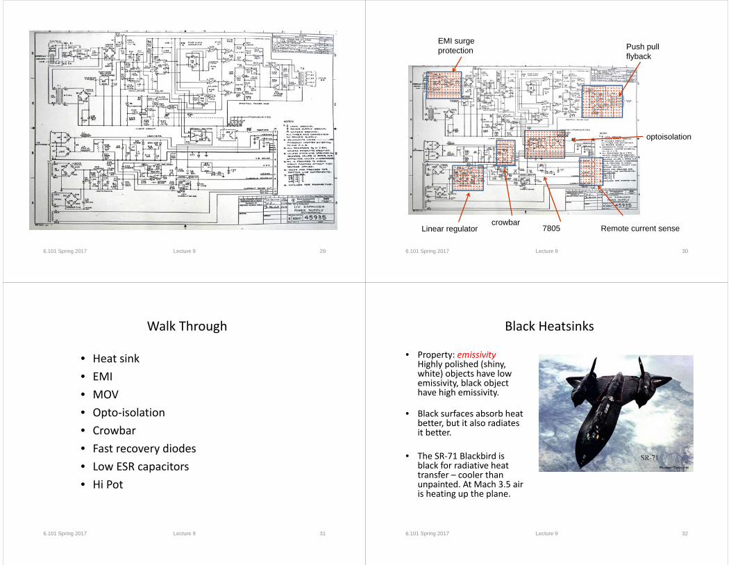
6.101 Spring 2017 Lecture 9 29 6.101 Spring 2017 Lecture 9 30
EMI surge protection Push pull
flyback
optoisolation
crowbarRemote current senseLinear regulator 7805
Walk Through
• Heat sink• EMI• MOV• Opto‐isolation• Crowbar• Fast recovery diodes• Low ESR capacitors• Hi Pot
6.101 Spring 2017 Lecture 9 31
Black Heatsinks
• Property: emissivity Highly polished (shiny, white) objects have low emissivity, black object have high emissivity.
• Black surfaces absorb heat better, but it also radiates it better.
• The SR‐71 Blackbird is black for radiative heat transfer – cooler than unpainted. At Mach 3.5 air is heating up the plane.
6.101 Spring 2017 Lecture 9 32

EMI Filter
6.101 Spring 2017 Lecture 9 33
http://www.murata.com/products/catalog/pdf/c35e.pdf
MOV
• Metal Oxide Varistor• Zinc Oxide + other metal
oxide forming small multiple back to back diodes
• Specs: – energy rating in joules, – operating voltage, – response time, – maximum current, – breakdown (clamping) voltage.
• Key component in surge protectors
6.101 Spring 2017 Lecture 9 34
Littlefuse MOV
6.101 Spring 2017 Lecture 9 35
Push Pull Flyback
6.101 Spring 2017 Lecture 9 36
High breakdown voltage
Low beta

6.101 Spring 2017 Lecture 9 37
Optoisolators
• Electrically isolate circuits in two voltage domains
• Isolator achieved through vacuum or air gap
• Typical isolation: 5000 volts rms
Crowbar
• Circuit to protect against overvoltage failure
• Overvoltage triggers SCR/TRIAC
• Relies on overcurrent protection or fuse.
6.101 Spring 2017 Lecture 9 38
6.101 Spring 2017 Lecture 9 39
Fast Recovery Diodes
Fast recovery times achieved by manipulating doping levels and junction geometry
Low ESR Capacitors
• ESR – Equivalent Series Resistance• Electrolytic 10uf: 0.1‐3Ω• Ceramic, low ESR: <0.015Ω
6.101 Spring 2017 Lecture 9 40

Hi Pot
• Safety test to verify isolation between primary and secondary.
• High potential test
6.101 Spring 2017 Lecture 9 41
Switching Power Supply Losses
• Inductor loss• Capacitor ESR loss• Diode loss• BJT/MOSFET conduction loss• BJT/MOSFET rise/fall time loss• Gate drive loss
6.101 Spring 2017 Lecture 9 42