atv71 and atv32 on ethernetip - assemblies 20-70 - … and atv32 on ethernet/ip with m340 and...
TRANSCRIPT

ATV71 and ATV32 on Ethernet/IP with M340 and NOC0401 configured on Unity V6.0
Assemblies 20 – 70

Unity Hardware catalog update ...................... ..........................................................3 Adding the NOC0401................................. ................................................................4
Way properties ..................................... .............................................................................................. 5 TCP/IP parameters .................................. ........................................................................................... 5
Configuration of the Drive Network parameter ....... ................................................6
ATV71.................................................................................................................................................. 6 ATV32.................................................................................................................................................. 6
Description of topology used in this programming ex ample ................................6 Assemblies 20-70 ................................... ...................................................................7
Assembly Size...................................... .............................................................................................. 7 Assembly 20: CIP basic speed control output........ ........................................................................ 7
Assembly mapping ........................................................................................................................... 7 CIP basic command Word ............................................................................................................... 7
Assembly 70: CIP basic speed control input ......... ......................................................................... 7 Assembly mapping ........................................................................................................................... 7 CIP basic status word....................................................................................................................... 7
Drive configuration ................................ ............................................................................................ 8 ATV71 command and reference configuration ................................................................................ 8 ATV71 Communication scanner configuration................................................................................. 9 ATV32 command and reference configuration ................................................................................ 9 ATV32 Communication scanner configuration............................................................................... 10
PLC configuration.................................. .......................................................................................... 10 ATV71 ............................................................................................................................................ 10 Configuration of ATV71 in Unity..................................................................................................... 11 Command example of ATV71 ........................................................................................................ 14 ATV32 ............................................................................................................................................ 15 Configuration of ATV32 in Unity..................................................................................................... 16 Command example of ATV32 ........................................................................................................ 19
EtherNet/IP Explicit Messaging Using DATA_EXCH ..... .......................................20
Get Single Attribute ............................... .......................................................................................... 20 ATV71 ............................................................................................................................................ 20 ATV32 ............................................................................................................................................ 21
Set Single Attribute............................... ........................................................................................... 22 ATV71 ............................................................................................................................................ 22 ATV32 ............................................................................................................................................ 23

The goal of this document is to describe how configure the M340 with NOC0401 with Unity V6.0 in order to command ATV71 and ATV32 over Ethernet/IP. The particularity of NOC0401 configured on Unity V6.0 is the using of DTM to configure the EthernetIP Device. Before starting the configuration, you need to update the DTM in Unity hardware catalog.
Unity Hardware catalog update On the first using the hardware catalog is empty. To update it select “External update tool”
When the window FDT/DTM catalog is open, click on “Update”.

When the update is done, the FDT/DTM catalog is closed and the hardware catalogue is display. The button update catalog can be used to update the list of DTM scan and add it in the hardware catalog.
Adding the NOC0401 Insert of the NOC0401, in the PLC rack.
You will have access to the NOC0401 configuration through the Unity DTM browser. Double click on the NOC0401 to open the configuration.

Way properties
TCP/IP parameters
At this step, the Unity contains the Ethernet/IP DTM and the NOC0401 have his network parameter. The next step is to define the network parameters for the Drive.

Configuration of the Drive Network parameter
ATV71 These parameters are located in [1.9 - COMMUNICATION] (COM-) � menu [ETHIP] (Eth) IP address of card IP mask of card IP gate (if needed) Services Note: A power cycle is necessary to take into account a change on these parameters
ATV32 These parameters are located in [COMMUNICATION] (COM-) � menu [COMMUNICATION CARD] (Cbd) Ethernet Protocol: choose Ethernet IP. Mode IP IP address of card IP mask of card IP gate (if needed) Services OCA1 to OCA6: Scanner output OMA1 to OMA6: Scanner input Note: A power cycle is necessary to take into account a change on these parameters At this step, the drive is configured with his network parameter. Now we have to choose the wishes assemblies and configure it in the Unity configuration.
Description of topology used in this programming ex ample � The PLC is a M340 with CPU P342030 and NOC0401 for Ethernet/IP � ATV71 + Ethernet/IP card (VW3A3316) � ATV32 + Ethernet card (VW3A3616) � PC with Unity V6.0 connect to the Ethernet/IP network

Assemblies 20-70
Assembly Size
Assembly 20: CIP basic speed control output
Assembly mapping
CIP basic command Word
Assembly 70: CIP basic speed control input
Assembly mapping
CIP basic status word

Drive configuration
ATV71 command and reference configuration In this case the ATV71 must be configured in the Drivecom profile with separate mode with one the following parameter. You can choose one of the both table describe below, but when you choose all the parameter describe in this table have to be configured like describe. If one of the following parameter are not configured like describe, the drive will display EPF2 fault. Example: You can see that the command switching and reference switching must be configured to C312 and C313 even if you don’t need it.
Or
Note: It is not possible to configure the display terminal as a channel. To switch to the display terminal, use the function force local and assign the parameter [Forced local Ref.] to [HMI] (LCC). Important Selection of the command and reference channel For the assemblies 20, the default settings for the reference are originated from the terminals. To fully control the drive from the network the following operation is required: The object 2A/1/4 (netref ) must be changed from 0 to 1. Such assignment can be done:
- By program, with a messaging block. - With the Class instance editor
The way to write the NetRef will be describe after in this document.

ATV71 Communication scanner configuration In the ATV71, the assemblies word are configured in the Drive communication scanner (NCAx and NMAx). These parameters are located in [1.9 - COMMUNICATION] (COM-) � menu [COM. SCANNER INPUT] and [COM. SCANNER OUTPUT]. It’s also possible to configure it via the embedded web server Here with assemblies 20-70, the size is fixed to 2 in input and 2 for output. The drive communication scanners must be configured to Output assembly 20
Input assembly 70
ATV32 command and reference configuration In this case the ATV32 must be configured in the Drivecom profile with separate mode with one the following parameter. You can choose one of the both table describe below, but when you choose all the parameter describe in this table have to be configured like describe. If one of the following parameter are not configured like describe, the drive will display EPF2 fault. Example: You can see that the command switching and reference switching must be configured to C312 and C313 even if you don’t need it.

Important Selection of the command and reference channel For the assemblies 20, the default settings for the command and the reference are originated from the terminals. To fully control the drive from the network the following operation is required: The object 2A/1/4 (netref ) must be changed from 0 to 1. And the object 29/1/5 (netrctrl ) must be changed from 0 to 1. Such assignment can be done:
- By program, with a messaging block. - With the Class instance editor
The way to write the NetRef and the NetCtrl will be describe after in this document.
ATV32 Communication scanner configuration In the ATV32, the assemblies word are configured in the Drive communication scanner (OCAx and 0MAx). These parameters are located in [COMMUNICATION] (COM-) � menu [COMMUNICATION CARD] (Cbd) It’s also possible to configure it via the embedded web server Here with assemblies 20-70, the size is fixed to 2 in input and 2 for output. The drive communication scanners must be configured to Output assembly 20
Input assembly 70
PLC configuration
ATV71 In the DTM browser, right click on the NOC module and then click on “Add”.
Then you can choose the ATV71 Ethernet/IP DTM corresponding to your version.

Important: If you have already install SoMove on your computer, the ATV71 drive DTM are also detected and could be selected. Drive DTM coming from SoMove (don’t use it in Unity):
Like it’s a drive DTM, it contains only drive parameter. Not the Ethernet/IP parameter. So Unity will reject it.
The Drive Ethernet/IP DTM which can be used are describe with “From EDS”
Configuration of ATV71 in Unity By default the Assemblies 20-70 are already configured
After adding the ATV71, you can open the NOC0401 configuration with the DTM browser.

By default, the Item (mean the scanner definition in the PLC) is in automatic mode. But the automatic mode doesn’t have the good size and format. So it’s needed to modify the Item in manual mode

Then we will define the Item size and format.
Final view with the input correctly configured
Repeat the same step to configure the output item
Then you can applied the configuration and close this view. In the NOC configuration, it’s needed to reserve the %MW for the scanner exchange. We need 16 %MW in input just for the NOC Health bit and 16 %MW in output for the NOC control bit. In addition to these %MW, the scanner add also other %MW. Here we will have in input 16 %MW + 2%MW for ATV71 and 2%MW for ATV32 = 20 %MW. And we will have in output 16 %MW + 2%MW for ATV71 and 2%MW for ATV32 = 20 %MW.

Here I will reserve 20 % MW in input and 20 % MW in output.
Generate the Program to build the scanner variable.
The cyclic exchange will be done with these variables. ATV71_BLOCKA_IW0: CIP basic Status word ATV71_BLOCKA_IW2: Speed feedback ATV71_BLOCKA_QW0: CIP basic Command word
ATV71_BLOCKA_QW2: Speed reference.
Command example of ATV71 Remind: First of all it’s needed to write the NetRef (2A/01/04) bit in order to give the reference channel to the Ethernet/IP card. So connect the NOC0401 and open the explicit messaging for Ethernet/IP

When it’s done, the command and the reference come from Ethernet/IP. To start the drive, respect the bit of assemblies describe before.
� Start command give by bit 0 of ATV71_BLOCKA_QW0 � The Speed reference is writing to 500rpm in the ATV71_BLOCKA_QW2 � The status is indicated in Running: bit 2 of ATV71_BLOCKA_IW0 � The speed feedback is read to 500 in ATV71_BLOCKA_IW2
ATV32 In the DTM browser, right click on the NOC module and then click on “Add”.
Then you can choose the ATV71 Ethernet/IP DTM corresponding to your version.

Important: If you have already install SoMove on your computer, the ATV32 drive DTM are also detected and could be selected. Drive DTM coming from SoMove (don’t use it in Unity):
Like it’s a drive DTM, it contains only drive parameter. Not the Ethernet/IP parameter. So Unity will reject it.
The Drive Ethernet/IP DTM which can be used are describe with “From EDS”
Configuration of ATV32 in Unity By default the Assemblies 20-70 are already configured
After adding the ATV32, you can open the NOC0401 configuration with the DTM browser.

By default, the Item (mean the scanner definition in the PLC) is in automatic mode. But the automatic mode doesn’t have the good size and format. So it’s needed to modify the Item in manual mode.
Then we will define the Item size and format.

Final view with the input correctly configured
Repeat the same step to configure the output item
Then you can applied the configuration and close this view. In the NOC configuration, it’s needed to reserve the %MW for the scanner exchange. We need 16 %MW in input just for the NOC Health bit and 16 %MW in output for the NOC control bit. In addition to these %MW, the scanner add also other %MW. Here we will have in input 16 %MW + 2%MW for ATV71 and 2%MW for ATV32 = 20 %MW. And we will have in output 16 %MW + 2%MW for ATV71 and 2%MW for ATV32 = 20 %MW. Here I will reserve 20 % MW in input and 20 % MW in output.
Generate the Program to build the scanner variable.
The cyclic exchange will be done with these variables. ATV32_BLOCKA_IW0: CIP basic Status word ATV32_BLOCKA_IW2: Speed feedback ATV32_BLOCKA_QW0: CIP basic Command word
ATV32_BLOCKA_QW2: Speed reference.

Command example of ATV32
Remind: First of all it’s needed to write the NetRef (2A/01/04) and the NetCtrl (29/01/05) bit in order to give the command and reference channel to the Ethernet/IP card. So connect the NOC0401 and open the explicit messaging for Ethernet/IP
Note: Repeat the same writing but for the NetCtrl (41/01/05 in decimal) When it’s done, the command and the reference come from Ethernet/IP. To start the drive, respect the bit of assemblies describe before.
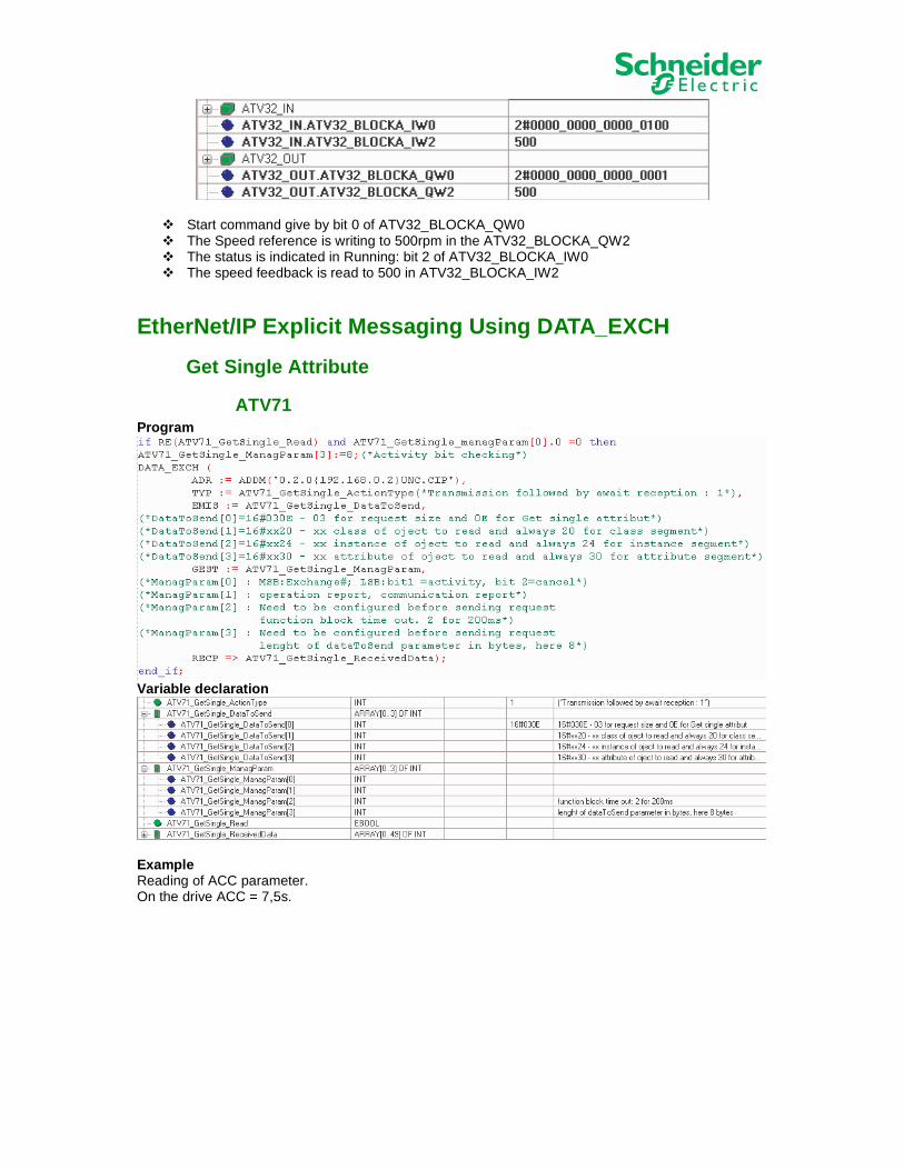
� Start command give by bit 0 of ATV32_BLOCKA_QW0 � The Speed reference is writing to 500rpm in the ATV32_BLOCKA_QW2 � The status is indicated in Running: bit 2 of ATV32_BLOCKA_IW0 � The speed feedback is read to 500 in ATV32_BLOCKA_IW2
EtherNet/IP Explicit Messaging Using DATA_EXCH
Get Single Attribute
ATV71 Program
Variable declaration
Example Reading of ACC parameter. On the drive ACC = 7,5s.

When the ATV71_GetSingle_Read is equal to 1, the reading start. The result of reading is in register ATV71_GetSingle_ReceivedData[2] = 75
ATV32 Program
Variable declaration
Example Reading of ACC parameter. On the drive ACC = 4,1s. When the ATV32_GetSingle_Read is equal to 1, the reading start.

The result of reading is in register ATV32_GetSingle_ReceivedData[2] = 41.
Set Single Attribute
ATV71 Program
Variable declaration
Example Reading of ACC parameter. The data to write in the ATV71, is located in the register ATV71_SetSingle_DataToSend[4]. Here we write 123.

When the ATV71_SetSingle_Write is equal to 1, the writing start. On the drive display we see the ACC = 12,3s.
ATV32 Program
Variable declaration
Example Reading of ACC parameter. The data to write in the ATV32, is located in the register ATV32_SetSingle_DataToSend[4]. Here we write 345.
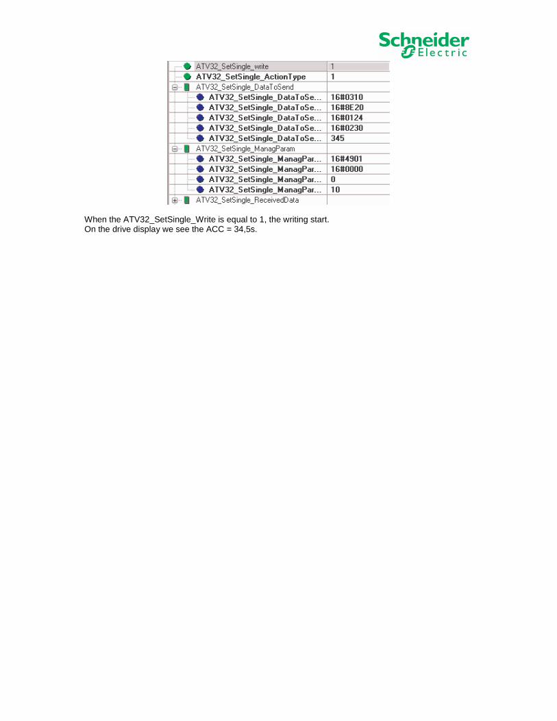
When the ATV32_SetSingle_Write is equal to 1, the writing start. On the drive display we see the ACC = 34,5s.