atul plc report
TRANSCRIPT

8/3/2019 Atul Plc Report
http://slidepdf.com/reader/full/atul-plc-report 1/42
“PROGRAMMABLE LOGIC CONTROLLER”
Seminar report submitted in partial fulfillment of the requirement for the award of the
degree of
BACHELOR OF TECHNOLOGY
IN
ELECTRONICS & INSTRUMENTATION ENGINEERING
(UTTAR PRADESH TECHNICAL UNIVERSITY)
BY
ATUL KUMAR SRIVASTAVA
E.I. 6TH SEMETER
Roll No. 0821632008
Under the guidance of
MS. SWETA PANDEY
DEPARTMENT OF ELECTRONICS & INSTRUMENTATION ENGINEERING
IIMT COLLEGE OF ENGINEERING
GREATER NOIDA
8/3/2019 Atul Plc Report
http://slidepdf.com/reader/full/atul-plc-report 2/42

8/3/2019 Atul Plc Report
http://slidepdf.com/reader/full/atul-plc-report 3/42
Certificate
THIS IS TO CERTIFY THAT Mr.ATUL KUMAR SRIVASTAVA OF
B.TECH(3RDYEAR) ELECTRONICS AND INSTRUMENTATION ENGINEERING
DELIEVERED A SEMINAR AT “PROGRAMMABLE LOGIC CONTROL” is ON
11-03-2011. ACCORDING TO THE GAUTAM BUDDH TECHNICAL UNIVERSITY
CIRRICULUM HIS PERFORMANCE IN THE SEMINAR WAS EXCELLENT/VERY
GOOD /SATISFACTORY.
Ms.Swta Pandey Mrs.Taslima Ahmed
(SEMINAR GUIDE) (SEMINAR COORDINATOR)
Mr.UMESH KUMAR
(HEAD OF DEPARTMENT)

8/3/2019 Atul Plc Report
http://slidepdf.com/reader/full/atul-plc-report 4/42
INDEX
Chapter No. Topics Page No.
1. Introduction 01
2. PLC Architecture 03
3. System Overview. 08
4. Hardware Configuration 10
5. Addresses 15
6. Software Description. 18
7. Syntax for Program 25
8. How to Use PLC. 26
9. Scope of Future Expansion. 28
10. Applications of PLC. 29
BIBLIOGRAPHY 32
APPENDIX A Automatic Mixing System. 33

8/3/2019 Atul Plc Report
http://slidepdf.com/reader/full/atul-plc-report 5/42
Chapter 1
8/3/2019 Atul Plc Report
http://slidepdf.com/reader/full/atul-plc-report 6/42
INTRODUCTION
Simplification of engineering and precise control of manufacturing
process can result in significant cost savings. The most cost-effective way, which
can pay big dividends in the long run, is flexible automation; a planned approachtowards integrated control systems. It requires a conscious effort on the part of
plant managers to identify areas where automation can result in better
deployment/utilization of human resources and savings in man-hours, down time.Automation need not be high ended and too sophisticated; it is the phased, step-
by-step effort to automate, employing control systems tailored to one’s specific
requirements that achieves the most attractive results. That is where Industrial
electronics has been a breakthrough in the field of automation and controltechniques.
ROLE OF ELECTRONICS IN AUTOMATION
A constant demand for better and more efficient manufacturing and process machinery has led to the requirement for higher quality and reliability in
control techniques. With the availability of intelligent, compact solid state
electronic devices, it has been possible to provide control systems that can reduce
maintenance, down time and improve productivity to a great extend. By installingefficient and user friendly industrial electronics systems for manufacturing
machinery or processors, one can obtain a precise, reliable and prolific means for
generating quality products.Considering the varied demand and increasing competition, one has to
provide for flexible manufacturing process. One of the latest techniques in solid
state controls that offers flexible and efficient operation to the user is
“PROGRAMMABLE CONTROLLERS”. The basic idea behind these
programmable controllers was to provide means to eliminate high cost associated
with inflexible, conventional relay controlled systems. Programmable controllersoffer a system with computer flexibility:
1. Suited to withstand the industrial environment
2. Has simplicity of operation
3. Maintenance by plant technicians and
4. Reduce machine down time and provide expandability for future.
DEFINATION OF PLC
8/3/2019 Atul Plc Report
http://slidepdf.com/reader/full/atul-plc-report 7/42
A Programmable controller is a solid state user programmable control system
with functions to control logic, sequencing, timing, arithmetic data manipulation andcounting capabilities. It can be viewed as an industrial computer that has a central
processor unit, memory, input output interface and a programming device. The central
processing unit provides the intelligence of the controller. It accepts data, statusinformation from various sensing devices like limit switches, proximity switches,
executes the user control program store in the memory and gives appropriate output
commands to devices like solenoid valves, switches etc.Input output interface is the communication link between field devices and the
controllers; field devices are wired to the I/O interfaces. Through these interfaces the
processor can sense and measure physical quantities regarding a machine or process, such
as, proximity, position, motion, level, temperature, pressure, etc. Based on status sensed,the CPU issues command to output devices such as valves, motors, alarms, etc.
Programmer unit provides the man machine interface. It is used to enter the application
program, which often uses a simple user-friendly logic.
BENEFITS OF PROGRAMMABLE CONTROLLERS
1. Programmable controllers are made of solid state components and hence
provide high reliability.
2. They are flexible and changes in sequence of operation can easily be
incorporated due to programmability. They may be modular in nature and
thus expandability and easy installation is possible.
3. Use of PLC results in appreciable savings in Hardware and wiring cost.
4. They are compact and occupy less space.
5. Eliminate hardware items like Timers, counters and Auxiliary relays. The presence for timers and counters has easy accessibility.
6. PLC can control a variety of devices and eliminates the need for
customized controls.
7. It has total protections against obsolescence and has wide scope for upgradation.
Chapter 2
8/3/2019 Atul Plc Report
http://slidepdf.com/reader/full/atul-plc-report 8/42
PLC ARCHITECTURE
PLCs contain three basic sections:
1. Central processing unit (CPU).
2. Memory: EPROM, RAM, and so on.
3. Input/output section for communication with peripherals (ADC, DAC).
A PLC is basically a black box with a number of inputs from, and a number of
outputs to, the outside world. It can make decisions, store data, do timing cycles, dosimple arithmetic, convert codes, and so on. The basic difference between this black
box and a hardware logic system using IC chips or a relay controlled system, is that
specific coded messages are stored in areas called program memory, which are
PROM or ROM and RAM chips. It is, however, much easier to change a programwhen a different process is required than to rewire the control system. For example,
it may take electricians a couple of weeks to require a pipe mill, whereas a programmer will spend only a fraction of this time to reprogram a PLC since no wires
will have to be changed. In addition, various recipes can be stored in memory and
accessed when required, making the program extremely flexible.The system operates through interaction with the processor and program memory.
When the power to the system is turned on, the processor reads the first instruction
stored in memory and acts on this instruction. When completed, it goes back to the
memory for the next instruction, and so on until task is complete. This operation iscalled the fetch-execute cycle. The processor communicates with the outside world
via input and output modules.
THE PARTS OF A PROGRAMMABLE CONTROLLER
Programmable logic controllers (PLC) can be considered to have three parts:
1. Input/output Section
The I/O section contains input modules and output modules. Functionally, the input
modules are equivalent to the signal converters (i.e. Analog to Digital or high power to
low power). All modern PLC input modules use optical devices to accomplishelectrically isolated coupling between the input circuit and the processor electronics.
Each input device is wired to a particular input terminal on the I/O section. Thus if the
switch is closed, 5v dc appears on input terminal, converts this dc voltage to a digital 1and sends it to the processor via programmable peripheral interface (PPI). Conversely, if
the switch is open, no dc voltage appears on input terminal. Input section will respond to
this condition by sending a digital 0 to the processor. The other input terminals behave
identically.
8/3/2019 Atul Plc Report
http://slidepdf.com/reader/full/atul-plc-report 9/42
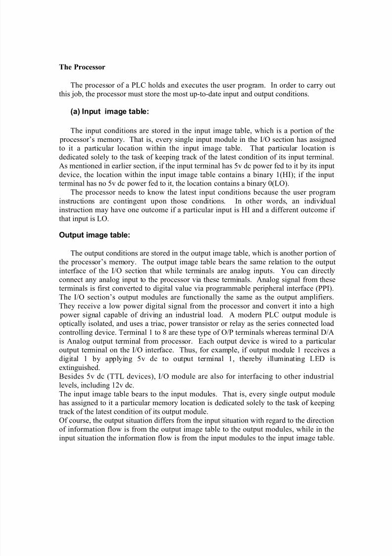
The Processor
The processor of a PLC holds and executes the user program. In order to carry out
this job, the processor must store the most up-to-date input and output conditions.
(a) Input image table:
The input conditions are stored in the input image table, which is a portion of the
processor’s memory. That is, every single input module in the I/O section has assignedto it a particular location within the input image table. That particular location is
dedicated solely to the task of keeping track of the latest condition of its input terminal.
As mentioned in earlier section, if the input terminal has 5v dc power fed to it by its input
device, the location within the input image table contains a binary 1(HI); if the inputterminal has no 5v dc power fed to it, the location contains a binary 0(LO).
The processor needs to know the latest input conditions because the user programinstructions are contingent upon those conditions. In other words, an individualinstruction may have one outcome if a particular input is HI and a different outcome if
that input is LO.
Output image table:
The output conditions are stored in the output image table, which is another portion of the processor’s memory. The output image table bears the same relation to the output
interface of the I/O section that while terminals are analog inputs. You can directly
connect any analog input to the processor via these terminals. Analog signal from these
terminals is first converted to digital value via programmable peripheral interface (PPI).The I/O section’s output modules are functionally the same as the output amplifiers.
They receive a low power digital signal from the processor and convert it into a high
power signal capable of driving an industrial load. A modern PLC output module isoptically isolated, and uses a triac, power transistor or relay as the series connected load
controlling device. Terminal 1 to 8 are these type of O/P terminals whereas terminal D/A
is Analog output terminal from processor. Each output device is wired to a particular output terminal on the I/O interface. Thus, for example, if output module 1 receives a
digital 1 by applying 5v dc to output terminal 1, thereby illuminating LED is
extinguished.Besides 5v dc (TTL devices), I/O module are also for interfacing to other industrial
levels, including 12v dc.
The input image table bears to the input modules. That is, every single output module
has assigned to it a particular memory location is dedicated solely to the task of keepingtrack of the latest condition of its output module.
Of course, the output situation differs from the input situation with regard to the direction
of information flow is from the output image table to the output modules, while in theinput situation the information flow is from the input modules to the input image table.
8/3/2019 Atul Plc Report
http://slidepdf.com/reader/full/atul-plc-report 10/42
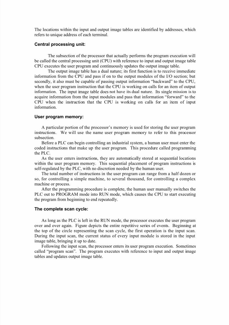
The locations within the input and output image tables are identified by addresses, which
refers to unique address of each terminal.
Central processing unit:
The subsection of the processor that actually performs the program execution will be called the central processing unit (CPU) with reference to input and output image table
CPU executes the user program and continuously updates the output image table.
The output image table has a dual nature; its first function is to receive immediateinformation from the CPU and pass if on to the output modules of the I/O section; but
secondly, it also must be capable of passing output information “backward” to the CPU,
when the user program instruction that the CPU is working on calls for an item of outputinformation. The input image table does not have its dual nature. Its single mission is to
acquire information from the input modules and pass that information “forward” to the
CPU when the instruction that the CPU is working on calls for an item of input
information.
User program memory:
A particular portion of the processor’s memory is used for storing the user program
instructions. We will use the name user program memory to refer to this processor subsection.
Before a PLC can begin controlling an industrial system, a human user must enter the
coded instructions that make up the user program. This procedure called programmingthe PLC.
As the user enters instructions, they are automatically stored at sequential locations
within the user program memory. This sequential placement of program instructions is
self-regulated by the PLC, with no discretion needed by the human user.The total number of instructions in the user program can range from a half dozen or
so, for controlling a simple machine, to several thousand, for controlling a complex
machine or process.After the programming procedure is complete, the human user manually switches the
PLC out to PROGRAM mode into RUN mode, which causes the CPU to start executing
the program from beginning to end repeatedly.
The complete scan cycle:
As long as the PLC is left in the RUN mode, the processor executes the user program
over and over again. Figure depicts the entire repetitive series of events. Beginning atthe top of the circle representing the scan cycle, the first operation is the input scan.During the input scan, the current status of every input module is stored in the input
image table, bringing it up to date.
Following the input scan, the processor enters its user program execution. Sometimescalled “program scan”. The program executes with reference to input and output image
tables and updates output image table.

8/3/2019 Atul Plc Report
http://slidepdf.com/reader/full/atul-plc-report 11/42
Throughout the user program execution, the processor continuously keeps its output
image table up to date, as stated earlier. However, the output modules themselves are not
kept continuously up to date. Instead, the entire output image table is transferred to theoutput module during the output scan following the program execution.
(d) Data Memory:
A PLC is a computer, after all. Therefore, it can perform arithmetic, numeric
comparisons, counting, etc. Naturally the numbers and data can change from one scancycle to the next. Therefore the PLC must have a section of its memory set aside for
keeping track of variable data, or numbers, that are involved with the user program. This
section of memory we will call data memory.
When the CPU is executing an instruction for which a certain data value must beknown, that data value is brought in from data memory. When the CPU executes an
instruction that provides a numerical result, that result is put out into data memory. Thus,
CPU can read from or write to the data memory. Understand that this relationship is
different from the relationship between the CPU and the user program memory. Whenthe user program is executing, the CPU can only reads from the user program memory,
never write to it.
(e) Operating System of PLC:
The function of the operating system is to present the user with the equivalent of anextended machine or virtual machine that is easier to program than the underlying
hardware.
Due to this operating system, PLC is very easy to program. It can be programmedusing electrical schemes with familiar relay symbols so that a plant electrician can easily
access the PLC. Even though he does not know the assembly language or even if he may
not have any familiarity with computers and electronics, he will be able to program thePLC.
The function of PLC Operating system is:
1. Loads the user program from programming device to program memory.
2. To read status of input devices.
3. To execute user program.
4. To form and update input image table.
5. As per the status of output image table controls the output devices.
6. To provide user-friendly functions.
This O.S. makes supervision over entire system, so O.S. programs are said to
running in supervisory mode.

8/3/2019 Atul Plc Report
http://slidepdf.com/reader/full/atul-plc-report 12/42
When the user completely enters his program in user memory, he transfers control
from PROGRAM mode to RUN mode. In RUN mode the control of the whole system is
transferred to operating system. Now operating system takes care of the whole systemsuch that the whole system becomes automatic and appears as magic to users.
Chapter 3
8/3/2019 Atul Plc Report
http://slidepdf.com/reader/full/atul-plc-report 13/42
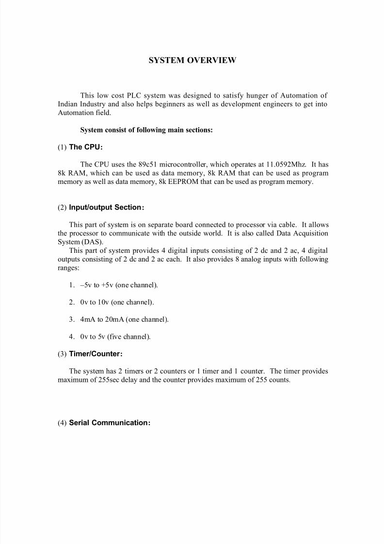
SYSTEM OVERVIEW
This low cost PLC system was designed to satisfy hunger of Automation of Indian Industry and also helps beginners as well as development engineers to get into
Automation field.
System consist of following main sections:
(1) The CPU:
The CPU uses the 89c51 microcontroller, which operates at 11.0592Mhz. It has
8k RAM, which can be used as data memory, 8k RAM that can be used as programmemory as well as data memory, 8k EEPROM that can be used as program memory.
(2) Input/output Section:
This part of system is on separate board connected to processor via cable. It allowsthe processor to communicate with the outside world. It is also called Data Acquisition
System (DAS).
This part of system provides 4 digital inputs consisting of 2 dc and 2 ac, 4 digital
outputs consisting of 2 dc and 2 ac each. It also provides 8 analog inputs with followingranges:
1. –5v to +5v (one channel).
2. 0v to 10v (one channel).
3. 4mA to 20mA (one channel).
4. 0v to 5v (five channel).
(3) Timer/Counter :
The system has 2 timers or 2 counters or 1 timer and 1 counter. The timer provides
maximum of 255sec delay and the counter provides maximum of 255 counts.
(4) Serial Communication:

8/3/2019 Atul Plc Report
http://slidepdf.com/reader/full/atul-plc-report 14/42
The system uses RS-232 serial data standard. Chip ICL232 is used as communication
interface between RS-232 standard and TTL logic.
(5) Programming Device:
This system uses personal computer (PC) as programming device. The user can write
program in user friendly language. The programming devices (PC) converts this user
friendly language program into machine understandable language and transmit it to thePLC board via serial communication.
(6) Power Supply Unit:
This system provides +12v and -12v with maximum 2amps and +5v with maximum
of 1amps.

8/3/2019 Atul Plc Report
http://slidepdf.com/reader/full/atul-plc-report 15/42
Chapter 4
HARDWARE CONFIGURATION
1. Microcontroller:
Here we are using 89c51 microcontroller, which has one full duplex serial data
receiver/transmitter, which is used for serial communication having interface with
ICL232 chip.
It has also two 16 bits timer/counter namely T0 and T1 which are used for timer andcounter applications. Timer T1 is used to set baud rate for serial communication in
program mode.
2. Memory:
The system consist of four types of memory:
a. 4k of EEPROM which is internal to 89c51 microcontroller. This memory is
used to store the operating system. It has address from 0000h to 0fffh. It canonly be accessed when the external access pin of controller is connected to
+5v. In our system this pin is permanently connected with +5v so external
program memory is accessed only when the address is beyond 0fffh.
b. 8k of RAM which is used as data memory. The CPU can read data from and
write data into this memory. This memory has address from 0000h to 1fffh.
c. 8k of RAM which is used as data memory as well as program memory. The
CPU can write program codes in and read program codes from this memory.
This memory has address from 2000h to 3fffh.
d. 8k of EEPROM, which is used as, program memory. The subroutines, which
are helpful in executing the main program, are stored here. This memory has
location from 4000h to 5fffh.
3. Programmable Peripheral Interface(PPI):
Here two 8255 are used as PPI. One is used to control the ADC and DAC, while
other is used for Input/output interface. The addresses for the 8255 used to control ADC
and DAC are:
Port A: 6000h
8/3/2019 Atul Plc Report
http://slidepdf.com/reader/full/atul-plc-report 16/42
Port B: 6001h
Port C: 6002h
Control Word: 6003h
The addresses for the 8255 used for Input/output interfaces are:
Port A: 8000h
Port B: 8001h
Port C: 8002h
Control Word: 8003h
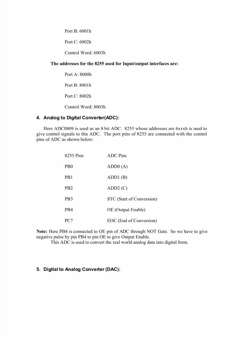
4. Analog to Digital Converter(ADC):
Here ADC0809 is used as an 8 bit ADC. 8255 whose addresses are 6xxxh is used togive control signals to this ADC. The port pins of 8255 are connected with the control
pins of ADC as shown below:
8255 Pins ADC Pins
PB0 ADD0 (A)
PB1 ADD1 (B)
PB2 ADD2 (C)
PB3 STC (Start of Conversion)
PB4 OE (Output Enable)
PC7 EOC (End of Conversion)
Note: Here PB4 is connected to OE pin of ADC through NOT Gate. So we have to give
negative pulse by pin PB4 to pin OE to give Output Enable.This ADC is used to convert the real world analog data into digital form.
5. Digital to Analog Converter (DAC):

8/3/2019 Atul Plc Report
http://slidepdf.com/reader/full/atul-plc-report 17/42
Here the only control signal is “Start of Conversion”, which is connected with PC0 of
8255 having address 6xxxh. For converting the digital data to analog form first make
PC0 low and then put digital data on port0 of 89c51. Now make PC0 high.This particular part of the system is idle in our application, but it is kept for future
expansion.
6. Serial Communication:
Here in-built transmitter/receiver of 89c51 is used for serial communication in
conjunction with chip ICL232. Here the transmitter/receiver is of asynchronous type
(UART). So the data is communicated byte by byte. The UART is working in serial
communication mode 1. So the timer T1 is used to set the baud rate. The baud rate is setto 2400.
7. Switches and Indicators:
Switches:
a. Power ON/OFF switch.
b. Reset Switch.
c. Program/Run mode Switch.
Indicators:
a. Power ON/OFF LED(red)
b. Reset LED(red)
c. Program mode LED(orange)
d. Run mode LED(green)
e. Fault LED(red, green, orange, yellow)
8. Digital Input:

8/3/2019 Atul Plc Report
http://slidepdf.com/reader/full/atul-plc-report 18/42
DC Input:
We have two digital DC inputs with following specifications:
1. 0v to 5v – LOW
2. 20v to 25v- HIGH
3. Optocoupler Isolation.
AC Input:
We have two digital AC inputs with following specifications:
1. 0v to 10v-LOW
2. 20v to 25v-HIGH
3. 47hz to 63hz frequency.
4. Optocoupler Isolation.
9. Digital Outputs:
DC outputs:
We here have two DC outputs with following specification:
1. 0v t0 3v-0v
2. 3.5v to 5v-24v
3. 0.5amp output current.
4. Optocoupler Isolation.
AC outputs:

8/3/2019 Atul Plc Report
http://slidepdf.com/reader/full/atul-plc-report 19/42
We have two relays as AC outputs with following specification:
1. 0v to 3v- relay OFF
2. 3.5v to 5v- relay ON
3. Optocoupler Isolation.
4. Relay with12v, 4ohm.

8/3/2019 Atul Plc Report
http://slidepdf.com/reader/full/atul-plc-report 20/42
Chapter 5
ADDRESSES
AC Output:
Output Address
Relay 1(Normally Open) 00
Relay 2(Normally Open) 01
Relay 1(Normally Close) 20
Relay 2(Normally Close) 21
DC Output:
Output Address
Out 1(Normally Open) 02
Out 2(Normally Open) 03
Out 1 (Normally Close) 22
Out 2 (Normally Close) 23
AC Input:
Input Address
In 1(Normally Open) 04
In 2(Normally Open) 05
In 1(Normally Close) 24
In 2(Normally Close) 25
8/3/2019 Atul Plc Report
http://slidepdf.com/reader/full/atul-plc-report 21/42
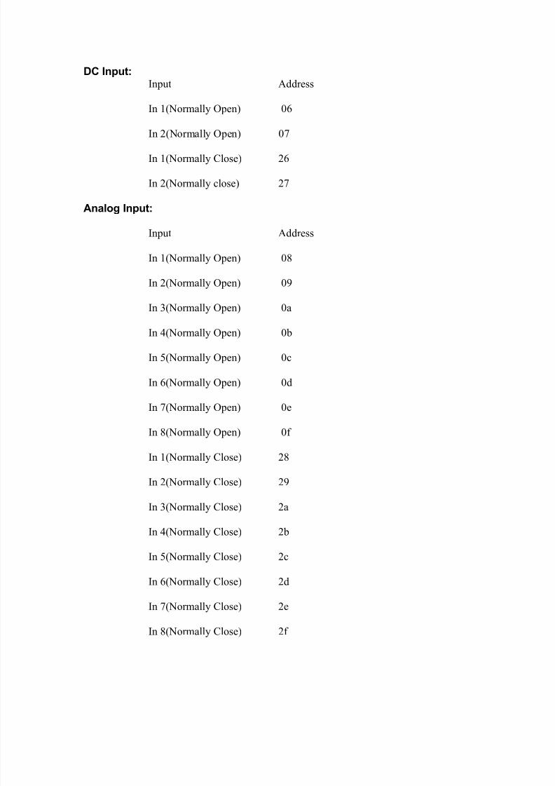
DC Input:Input Address
In 1(Normally Open) 06
In 2(Normally Open) 07
In 1(Normally Close) 26
In 2(Normally close) 27
Analog Input:
Input Address
In 1(Normally Open) 08
In 2(Normally Open) 09
In 3(Normally Open) 0a
In 4(Normally Open) 0b
In 5(Normally Open) 0c
In 6(Normally Open) 0d
In 7(Normally Open) 0e
In 8(Normally Open) 0f
In 1(Normally Close) 28
In 2(Normally Close) 29
In 3(Normally Close) 2a
In 4(Normally Close) 2b
In 5(Normally Close) 2c
In 6(Normally Close) 2d
In 7(Normally Close) 2e
In 8(Normally Close) 2f
8/3/2019 Atul Plc Report
http://slidepdf.com/reader/full/atul-plc-report 22/42
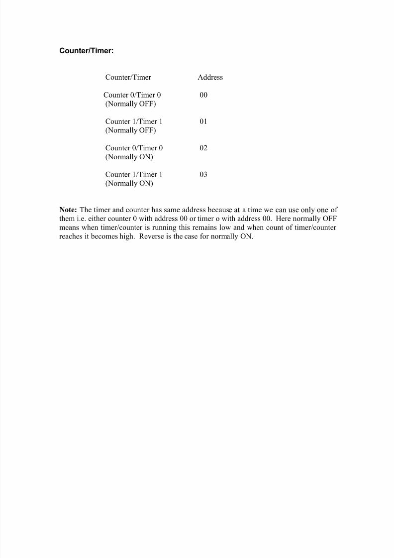
Counter/Timer:
Counter/Timer Address
Counter 0/Timer 0 00(Normally OFF)
Counter 1/Timer 1 01(Normally OFF)
Counter 0/Timer 0 02
(Normally ON)
Counter 1/Timer 1 03
(Normally ON)
Note: The timer and counter has same address because at a time we can use only one of them i.e. either counter 0 with address 00 or timer o with address 00. Here normally OFF
means when timer/counter is running this remains low and when count of timer/counter
reaches it becomes high. Reverse is the case for normally ON.

8/3/2019 Atul Plc Report
http://slidepdf.com/reader/full/atul-plc-report 23/42
8/3/2019 Atul Plc Report
http://slidepdf.com/reader/full/atul-plc-report 24/42
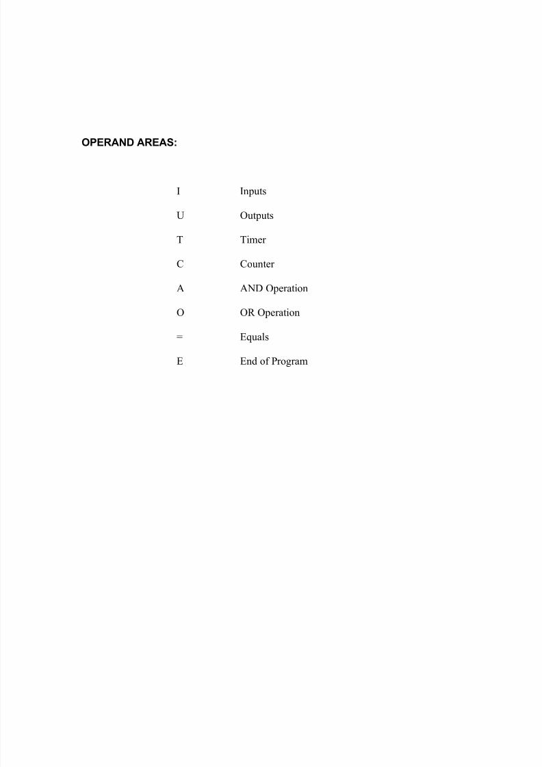
OPERAND AREAS:
I Inputs
U Outputs
T Timer
C Counter
A AND Operation
O OR Operation
= Equals
E End of Program

8/3/2019 Atul Plc Report
http://slidepdf.com/reader/full/atul-plc-report 25/42
STATEMENT LIST (STL) PROGRAMMING LANGUAGE:
In our system STL supports the following operations:
AND
OR
TIMER
COUNTER
AND Operation:
The AND operation scans to see if various conditions are satisfied simultaneously.
Circuit Diagram:
Output U 01 is “1” when all two inputs are “1”. The
Output is “0” if atleast one input is “0”.
I 04
I 05
U 01
Representation in Ladder Diagram: Representation in STL:
A I 04
A I 05I 04 I 05 U 01 = U 01
8/3/2019 Atul Plc Report
http://slidepdf.com/reader/full/atul-plc-report 26/42
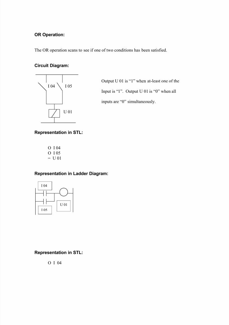
OR Operation:
The OR operation scans to see if one of two conditions has been satisfied.
Circuit Diagram:
Output U 01 is “1” when at-least one of the
I 04 I 05
Input is “1”. Output U 01 is “0” when all
inputs are “0” simultaneously.
U 01
Representation in STL:
O I 04
O I 05
= U 01
Representation in Ladder Diagram:
Representation in STL:
O I 04
I 04
I 05
U 01

8/3/2019 Atul Plc Report
http://slidepdf.com/reader/full/atul-plc-report 27/42
O I 05
A
O I 06O I 07
= U 01
AND before OR Operation:
Output U 01 is “1” when at-least one AND condition has been satisfied. Output U 01 is“0” when neither of the two AND conditions has been satisfied.
Representation in STL:
A I 04A I 05
O
A I 06A I 07
= U 01
Circuit Diagram: Ladder Diagram:
I 04
I 05
8/3/2019 Atul Plc Report
http://slidepdf.com/reader/full/atul-plc-report 28/42
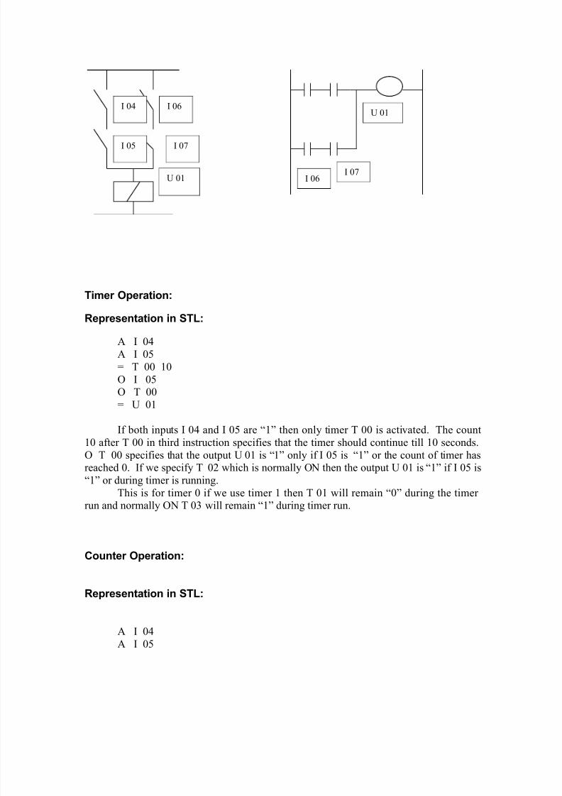
Timer Operation:
Representation in STL:
A I 04
A I 05
= T 00 10
O I 05O T 00
= U 01
If both inputs I 04 and I 05 are “1” then only timer T 00 is activated. The count
10 after T 00 in third instruction specifies that the timer should continue till 10 seconds.
O T 00 specifies that the output U 01 is “1” only if I 05 is “1” or the count of timer hasreached 0. If we specify T 02 which is normally ON then the output U 01 is “1” if I 05 is
“1” or during timer is running.
This is for timer 0 if we use timer 1 then T 01 will remain “0” during the timer run and normally ON T 03 will remain “1” during timer run.
Counter Operation:
Representation in STL:
A I 04
A I 05
I 04 I 06
I 05 I 07
U 01 I 06I 07
U 01

8/3/2019 Atul Plc Report
http://slidepdf.com/reader/full/atul-plc-report 29/42
= C 00 10
O I 06
O C 00= U 01
If both the inputs I 04 and I 05 are “1” then only counter 0 is activated. 10 in
third instruction represent the count of the counter. The output U 01 becomes “1” if input
I 06 is “1” or count of the counter becomes 0.Same applies for counter in normally ON and normally OFF mode as in case of
timer.
Chapter 7
SYNTAX FOR PROGRAM
1. Operand must be in upper case.
A I 04 right;
8/3/2019 Atul Plc Report
http://slidepdf.com/reader/full/atul-plc-report 30/42
Ai 04 wrong;
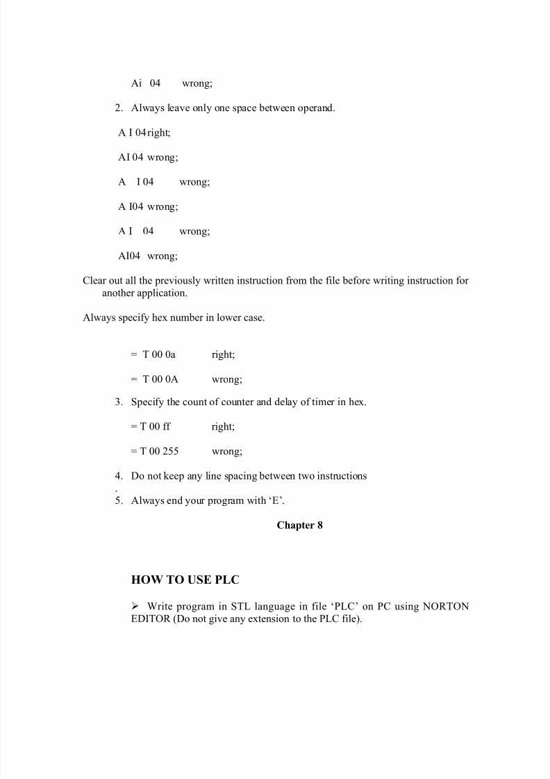
2. Always leave only one space between operand.
A I 04right;
AI 04 wrong;
A I 04 wrong;
A I04 wrong;
A I 04 wrong;
AI04 wrong;
Clear out all the previously written instruction from the file before writing instruction for
another application.
Always specify hex number in lower case.
= T 00 0a right;
= T 00 0A wrong;
3. Specify the count of counter and delay of timer in hex.
= T 00 ff right;
= T 00 255 wrong;
4. Do not keep any line spacing between two instructions
.5. Always end your program with ‘E’.
Chapter 8
HOW TO USE PLC
Write program in STL language in file ‘PLC’ on PC using NORTON
EDITOR (Do not give any extension to the PLC file).

8/3/2019 Atul Plc Report
http://slidepdf.com/reader/full/atul-plc-report 31/42
Switch on the PLC and confirm whether the power indicator LED ON or
not. If it is ON, switch the PLC in PROGRAM mode. Confirm that the REDLED indicating the PROGRAM mode is ON. Now PLC is ready for receiving
the control program written on PC.
Execute the program named “PLC” on PC in TC directory (i.e. TURBOC).
Wait till the message “PROGRAM IS TRANSMITTEDSUCCESSFULLY”.
Switch the PLC in RUN mode by changing the switch on RUN mode andthen press RESET switch. Confirm the GREEN LED indicating the RUN
mode is ON.
If one of the four FAULT LEDs is ON then check the reason and again
load whole of the program and repeat the above mentioned procedure.
TROUBLESHOOTING
If “POWER ON” LED (red) is OFF after switch ON the power, check the
FUSE. If blown then replace it.
If FAULT LED (red) is ON then “A” or “O” operand might have been
missing in start of instruction.
i.e. A I 04I 04
Correct it in the control program and again load the program.
If FAULT LED (green) is ON then “I” or “C” or “T” or “U” operand
might have been missing in instruction.
i.e. A I 05A 05
Correct it in the control program and again load the program.
If FAULT LED (saffron) is ON then “=” operand might be missing in
instruction.i.e. A I 05
A I 04
U 01
If FAULT LED (yellow) is ON then the TIMER/COUNTER is specified
other than ‘00’ or ‘01’.

8/3/2019 Atul Plc Report
http://slidepdf.com/reader/full/atul-plc-report 32/42
i.e. A I 04
A I 05
= T 02 0a
Correct it and load the control program once mor
SOFTWARE ANALYSIS
The higher-level language program on PC side converts the control programwritten in STL language into specific hex codes and transmits these codes to the PLC.
The codes are stored in RAM location in PLC.
The lower-level language program, which is stored in EEPROM internal to the
controller, reads hex codes from memory location one by one. It compares the code read
from the memory location with the predefined hex code and executes the instruction with
accordance to it.
As soon as we put the PLC in RUN mod, it reads the status of all the I/P. It stores
the status in bit addressable memory location as ‘1’ or ‘0’ depends upon the status. Nowit runs the program and performs operation on the status bit directed as user program. It
stores the result in another bit addressable memory location which are corresponds to the
O/P. After this it updates all the O/P.
The Flow chart of the ASSEMBLY LANGUAGE program is given below:
Chapter 9
SCOPE FOR FUTURE EXPANSION
♦ At present in our system we have 4 digital inputs and 4 digital outputs
which are interfaced with CPU through port C of 8255 having address 8xxxh.

8/3/2019 Atul Plc Report
http://slidepdf.com/reader/full/atul-plc-report 33/42
The port A and port B are not presently taken in use. By using these ports we can
expand digital inputs and outputs upto 8 digital inputs and outputs.
♦ Two memory slots of 8k each are not in present use. One of these slots
can be used for RAM and another one can be used for EEPROM. Using theseslots we can get more 8k of DATA memory using RAM and more 8k of
PROGRAM memory using EEPROM.
♦ Interfacing of DAC is provided on the PLC board, which can be used to
give an analog output.
♦ We can construct signal-conditioning circuit so we can directly connectthe transducers like PT100, thermocouple, LVDT etc.
♦ We can further construct PID controller module which can be switchedON or OFF by this PLC so we can control systems using continuous controller in
digital fashion.
♦ We can also design stepper motor controller, which can be interfaced with
PLC.
♦ Using chip 8279 we can provide keyboard and display facility on PLC board.
Chapter 10
APPLICATIONS OF PLC
8/3/2019 Atul Plc Report
http://slidepdf.com/reader/full/atul-plc-report 34/42
In the present industrial world, a flexible system that can be controlled by user atsite is preferred. Systems, whose logic can be modified but still, used without disturbing
its connection to external world, is achieved by PLC. Utilizing the industrial sensors
such as limit switches, ON-OFF switches, timer contact, counter contact etc., PLCcontrols the total system. The drive to the solenoid valves, motors, indicators,
enunciators, etc are controlled by the PLCs.
The above said controlling elements (normally called as inputs of PLCs) and
controlled elements (called as outputs of PLCs) exist abundantly in any industry. Theseinputs, outputs, timers, counters, auxiliary contacts are integral parts of all industries. As
such, it is difficult to define where a PLC cannot be used.
Proper application of a PLC begins with conversion of information into convenient parameters to save money, time and effort and hence easy operation in plants and
laboratories.
The areas where PLC is used maximum are as follows:
1. The batch processes in chemical, cement, food and paper industries which
are sequential in nature, requiring time of event based decisions iscontrolled by PLCs.
2. In large process plants PLCs are being increasingly used for automaticstart up and shut down of critical equipment. A PLC ensures that
equipment cannot be started unless all the permissive conditions for safe
start have seen established. It also monitors the conditions necessary for safe running of the equipment and trips the equipment whenever any
abnormality in the system is detected.
3. The PLC can be programmed to function as an energy managementsystem for boiler control for maximum efficiency and safety.
4. In automation of blender reclaimers
5. In automation of bulk material handling system at ports.
6. In automation for a ship unloader.
7. Automation for wagon loaders.
8. For blast furnace charging controls in steel plants.
9. In automation of brick moulding press in refractories.
10. In automation for galvanizing unit.
11. For chemical plants process control automation.
8/3/2019 Atul Plc Report
http://slidepdf.com/reader/full/atul-plc-report 35/42
12. In automation of a rock phosphate drying and grinding system.
13. Modernization of boiler and turbogenerator set.
14. Process visualization for mining application.
15. Criteria display system for power station.
16. As stored programmed automation unit for the operation of dieselgenerator sets.
17. In Dairy automation and food processing.
18. For a highly modernized pulp paper factory.
19. In automation system for the printing industry.
20. In automation of container transfer crane.
21. In automation of High-speed elevators.
22. In plastic moulding process.
23. In automation of machine tools and transfer lines.
24. In Mixing operations and automation of packaging plants.
25. In compressed air plants and gas handling plants.
26. In fuel oil processing plants and water classification plants.
27. To control the conveyor/classifying system.
Thus PLC is ideal for application where plant machine interlock requirements are
finalized at a later stage and need changes during engineering trial runs, commissioning
or normal use. It can be used extensively to replace conventional relay controls in power stations, refineries, cement, steel, fertilizer, petrochemical, chemical industries etc.
Applications can thus be extended from monitoring to supervision, control and
management.
8/3/2019 Atul Plc Report
http://slidepdf.com/reader/full/atul-plc-report 36/42
FUTURE OF PLCs
The PLC offers a compromise between advance control techniques and present day
technology. It is extremely difficult to forecast the rate and form of progress of PLCs,
but there is strong evidence that development is both rapid and cumulative. Though aPLC is not designed to replace a computer, it is useful and cost effective for medium
sized control systems. With the capability of functioning as local controllers in
distributed control systems. PLCs will retain their application in large process plants.
A further development of PLCs leads to the development of programmable function
controller (PFC) is compatible to PCs and directly controls the desired functions.
In India every process industry is replacing relay control systems by PLCs and will go
for PFCs in near future. In the near future every flats and offices may possess PFCs to
control room temperature, as elevator controller, maintain water tank levels, as small
telephone exchange etc.
BIBLIOGRAPHY
(1) PROGRAMMABLE LOGIC CONTROLLERS, OPERATION, INTERFACINGAND PROGRAMMING.
JOB DEN OTTER.
(2) IBM PC AND CLONES
GOVINDRAJALU.

8/3/2019 Atul Plc Report
http://slidepdf.com/reader/full/atul-plc-report 37/42
(3) MICROPROCESSORS AND INTERFACING PROGRAMMING AND
HARDWARE.
DOUGLAS HALL.
(4) THE 8051 MICROCONTROLLER ARCHITECTURE, PROGRAMMING AND
APPLICATIONS. KENNETH AYALA.
(5) MICROPROCESSOR ARCHITECTURE, PROGRAMMING ANDAPPLICATIONS.
RAMESH GAONKAR.
(6) MICROPROCESSORS AND MICROCOMPUTERS.
B. RAM.
(7) PROGRAMMING IN ANSI C.
E. BALAGURUSAMY.
(8) SIEMENS SIMATIC S5 PROGRAMMABLE CONTROLLER.
SYSTEM MANUAL.
(9) DIGITAL ELECTRONICS.
WIILIAM GOTHMAN.
(10) INTEGRATED CIRCUITS.
K R BOTKAR.
(11) DATA SHEETS FROM
NATIONAL SEMICONDUCTOR CORPORATION, INTEL, PHILLIPS,
FAIRCHILD SEMICONDUCTOR CORPORATION, MOTOROLA
CORPORATION.
(12) MAGAZINES – ELECTRONICS FOR YOU (EFY).
(13) OLD PROJECT REPORTS AND SEMINARS ON PLCS.
APPENDIX A
Automatic mixing system
Valve A Agitator

8/3/2019 Atul Plc Report
http://slidepdf.com/reader/full/atul-plc-report 38/42
Float switch 1
Valve B
Float switch 2
Problem:
In figure when START button is pressed, solenoid valve A is energized and a
batch of liquid is entered in tank. Float switch 1 detects the upper limit of liquid of liquid
level and Float switch 2 detects the lower limit of liquid. As, tank begins to fill, Switch 2closes. When the tank is full, switch 1 shuts off the solenoid valve A and start agitator tomix the liquid. The Agitator mixes the liquid for 30 seconds and shuts off. When the
Agitator turn off, solenoid valve B is energized to drain the liquid. After the tank has
been emptied, float switch 2 opens and solenoid B shuts off.
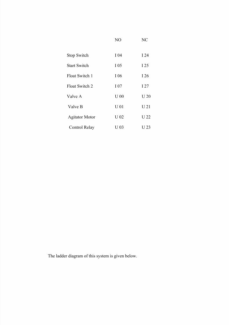
The Addresses of I/P and O/P are given below.
DEVICE ADDRESS
8/3/2019 Atul Plc Report
http://slidepdf.com/reader/full/atul-plc-report 39/42
NO NC
Stop Switch I 04 I 24
Start Switch I 05 I 25
Float Switch 1 I 06 I 26
Float Switch 2 I 07 I 27
Valve A U 00 U 20
Valve B U 01 U 21
Agitator Motor U 02 U 22
Control Relay U 03 U 23
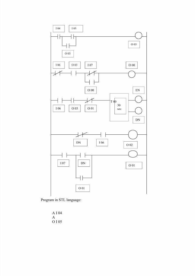
The ladder diagram of this system is given below.
8/3/2019 Atul Plc Report
http://slidepdf.com/reader/full/atul-plc-report 40/42
Program in STL language:
A I 04
A
O I 05
I 04 I 05
O 03
O 03
I 06 O 03 I 07
O 00
O 00
T 00
30
secI 06 O 03 O 01
EN
DN
DN I 06
O 02
I 07 DNO 01
O 01

8/3/2019 Atul Plc Report
http://slidepdf.com/reader/full/atul-plc-report 41/42
O U 03
= U 03
A I 26A U 03
A
O I 27O U 00
= U 00
A I 06A U 03
A U 21
= T 00 1f
A T 02A I 06
= U 02
A I 07
AO T 00
O U 01= U 01
E
Explanation of Ladder Diagram:
In first rung the stop switch is connected in series with start switch to
activate the control relay. The stop switch is normally close type where as start switch is
normally open type. So when the start switch is pressed control relay is activated. Thestart switch is push to on type so normally on contact of control relay is used to latch.
In second rung the NC contact of float switch 1 and NO contact of control relay is
in series with valve A. When start switch is pressed and the liquid level is below floatswitch 1 the valve A is opened and it is closed when level touches the float switch 1.The
NC contact of float switch 2 is latched by the NO contact of valve A so valve A does not
opened as soon as the level falls below the float switch 1 level and remain close till the
tank is fully emptied.In third rung the normally open contact of float switch 1is connected in series
with timer so when liquid level reaches to float switch 1, the timer is started.

8/3/2019 Atul Plc Report
http://slidepdf.com/reader/full/atul-plc-report 42/42