attachment d electromagnetic and communication assessment · attachment d electromagnetic and...
TRANSCRIPT

ATTACHMENT D
ELECTROMAGNETIC AND
COMMUNICATION ASSESSMENT


LAWRENCE DERRICK & ASSOCIATES
Bulgana Wind FarmElectromagnetic and Communication
Assessment
Lawrence Derrick B. E. (Elec.)8/26/2014
Final
This report examines the possible impacts of the proposed wind farm on existing radiocommunicationsand broadcasting services in the area and proposes interference mitigation strategies where necessary

Bulgana Wind Farm Vic - Electromagnetic and Radiocommunications Assessment of Project i
REV DATE DESCRIPION AUTHOR REVIEWED7 Feb 2014 Draft 1 for Bulgana WF Pty Ltd LJD WP, Enerfin15 Aug 2014 Draft 2 for Bulgana WF Pty Ltd LJD WP26 Aug 3014 Final for Bulgana WF Pty Ltd LJD
DISCLAIMER
This Report has been prepared on the basis of ACMA radiocommunications licensing data and broadcastinginformation and other reference material available in the public domain at the date of production of the report.The Report does not imply that any conclusions are not subject to change
Bulgana Wind Farm Vic - Electromagnetic and Radiocommunications Assessment of Project ii
EXECUTIVE SUMMARY
The site of the proposed Bulgana Wind farm covers approximately 7,524 hectares of private and public landlocated within the Bulgana, Joel Joel, South Joel, Congongella and Great Western districts, in central westernVictoria. It lies approximately 11.7 kilometres north of Ararat, at its southern extent, and 11.2 kilometres east ofStawell, at its north-west extent. Great Western is the nearest significant sized settlement approximately twokilometres to the south-west of the site
A number of existing Australian Communications and Media Authority (ACMA) registeredradiocommunication services are located in the general area and one point-to-point radio service crosses thewind farm nominal site boundaries. To ensure that the locations of turbines will not degrade the performance ofradio systems minimum separation distances and exclusion zones have been established for the turbinestructures.
Residences in the area surrounding the wind farm are provided with TV, FM Sound and other services fromhigh power transmitters located on Lookout Hill (the Ballarat stations). Low power transmitters in the generalarea at Halls Gap, Cobden and Horsham are not predicted to provide coverage around the wind farm site. Theother Western Victoria high power stations at Mt Dundas are also not predicted to cover the area. Based onAustralian Broadcasting Corporation(ABC) and Department of Broadband, Communications and the DigitalEconomy(DBCDE) interactive prediction maps some dwellings in the area may currently have variable TVcoverage from the terrestrial services and may need to rely on the Viewer Access Satellite Television(VAST) orpay TV satellite services. The TV/Sound broadcasting Licensees providing services to the area have beenidentified for advice for information to be initiated.
This Assessment provides an analysis of each of the radio facilities registered near the wind farm. It alsoestablishes recommended clearances based on accepted industry criteria for radio links crossing the wind farmand any required buffer zones for other radiocommunications sites. A study of the signal paths from the mainTV stations to the low power TV repeaters has been made to identify any potential interference to their inputsignals by wind turbines.
Comments are also provided on the radio interference and human exposure impacts from electric and magneticfields from powerlines and power transmission infrastructure associated with the wind farm.

Bulgana Wind Farm Vic - Electromagnetic and Radiocommunications Assessment of Project iii
TABLE OF CONTENTSEXECUTIVE SUMMARY ......................................................................................................................ii
1 INTRODUCTION ...........................................................................................................................1
1.1 Objective of this Assessment ..................................................................................................1
1.2 Scope.......................................................................................................................................1
1.3 Assumptions............................................................................................................................2
2 WIND TURBINE IMPACTS ON RADIO COMMUNICATIONS................................................2
2.1 Near-field Effects....................................................................................................................2
2.2 Diffraction...............................................................................................................................2
2.3 Reflection................................................................................................................................2
2.4 Omnidirectional Services ........................................................................................................3
3 RADIO SERVICES LOCATED NEAR BULGANA WF ..............................................................3
3.1 Point-to-point Systems............................................................................................................3
3.2 Off-Air Links to TV and FM Broadcasting Stations at Halls Gap, Ararat and Stawell. .........4
3.3 Air Services Facilities .............................................................................................................4
3.4 Point to Multipoint (PMP) Services ........................................................................................4
3.5 Bureau Of Meteorology Weather Radar .................................................................................5
3.6 Radio Sites in Close Proximity to Wind Turbines ..................................................................5
4 TV COVERAGE IN THE AREA....................................................................................................5
5 CUMULATIVE IMPACTS WITH PROPOSED WIND FARMS..................................................5
6 POWER TRANSMISSION INFRASTRUCTURE ELECTRIC AND MAGNETIC FIELDS.......6
7 MONITORING MASTS AND CONSTRUCTION ACTIVITY ....................................................7
8 DISCUSSION..................................................................................................................................7
8.1 Point-to-Point Links................................................................................................................7
8.2 TV and FM Broadcasting Services .........................................................................................7
8.3 Mobile Radio Base Stations ....................................................................................................8
9 RECOMMENDATIONS.................................................................................................................8
9.1 Point-to-point Links ................................................................................................................8
9.2 General Buffer Zones..............................................................................................................9
9.3 Interference to Television Reception ......................................................................................9
9.4 Interference to Radio Reception..............................................................................................9
10 CONCLUSIONS ........................................................................................................................... 10
11 REFERENCES .............................................................................................................................. 11
ATTACHMENT 1.................................................................................................................................. 12
WIND TURBINE GRID COORDINATES BULGANA WIND FARM............................................... 12
ATTACHMENT 2 - TELEVISION STATIONS & CHANNELS - BULGANA WIND FARM AREA................................................................................................................................................................ 14
ATTACHMENT 3.................................................................................................................................. 15
MAP OF RADIO LINKS & SITES OPERATING BELOW 1000 MHz............................................... 15
ATTACHMENT 4.................................................................................................................................. 16

Bulgana Wind Farm Vic - Electromagnetic and Radiocommunications Assessment of Project iv
MAP OF RADIO LINKS OPERATING BELOW 1000 MHz –DETAIL 1 .......................................... 16
ATTACHMENT 5.................................................................................................................................. 17
MAP OF RADIO LINKS & SITES OPERATING ABOVE 1000 MHz............................................... 17
ATTACHMENT 6.................................................................................................................................. 18
MAP OF RADIO LINKS OPERATING ABOVE 1000 MHz – DETAIL 1 ......................................... 18
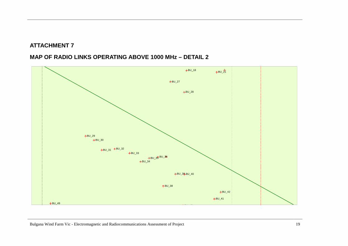
ATTACHMENT 7.................................................................................................................................. 19
MAP OF RADIO LINKS OPERATING ABOVE 1000 MHz – DETAIL 2 ......................................... 19
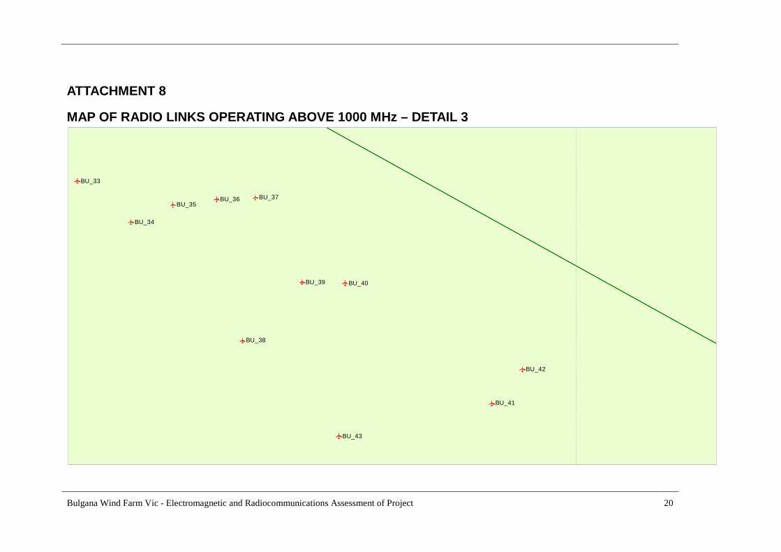
ATTACHMENT 8.................................................................................................................................. 20
MAP OF RADIO LINKS OPERATING ABOVE 1000 MHz – DETAIL 3 ......................................... 20
ATTACHMENT 9.................................................................................................................................. 21
MAP OF RADIO LINKS OPERATING ABOVE 1000 MHz – DETAIL 4 ......................................... 21
ATTACHMENT 10................................................................................................................................ 22
SAMPLE CALCULATIONS OF CLEARANCE ZONES .................................................................... 22
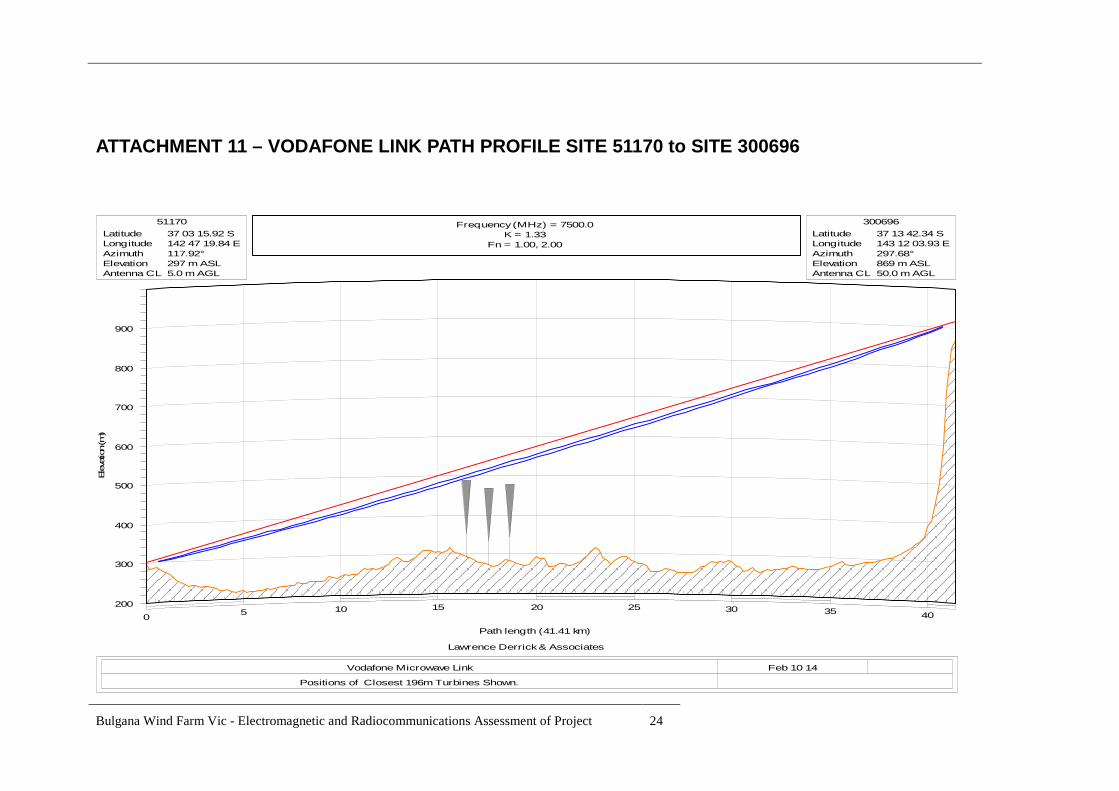
ATTACHMENT 11 – VODAFONE LINK PATH PROFILE SITE 51170 to SITE 300696 ................ 24
ATTACHMENT 12 – NBN CO. LINK PATH PROFILE SITE 51170 to SITE 133134 ...................... 25
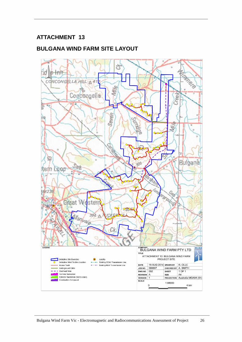
ATTACHMENT 13............................................................................................................................... 26
BULGANA WIND FARM SITE LAYOUT.......................................................................................... 26
ATTACHMENT 14............................................................................................................................... 27
BULGANA WIND FARM SITE - DWELLINGS WITHIN 5KM........................................................ 27
ATTACHMENT 15................................................................................................................................ 28
MAP OF WIND FARMS ADJACENT TO BULGANA WIND FARM............................................... 28
ATTACHMENT 16– ABC PREDICTED TV COVERAGE FOR MAIN STATIONS AT LOOKOUTHILL AND MT DUNDAS..................................................................................................................... 29
LIST OF TABLESTABLE 1 - MICROWAVE LINK CLEARANCES ................................................................................3TABLE 2 – LOCAL TV AND SOUND BROADCAST STATIONS .....................................................4TABLE 3 - POINT TO MULTIPONT SYSTEMS IN THE AREA ........................................................4TABLE 4 - TV STATION TRANSMITTER SITES ...............................................................................5TABLE 5 - WIND FARMS ADJACENT TO BULGANA WIND FARM .............................................6TABLE 6 – TYPICAL OVERHEAD TRANSMISSION LINE DIMENSIONS.....................................6TABLE 7 – RECOMMENDED CLEARANCES FOR RADIO POINT TO POINT LINK....................8TABLE 8 - RADIO LINK CLEARANCE COMPLIANCE ....................................................................9
Bulgana Wind Farm Vic - Electromagnetic and Radiocommunications Assessment of Project 1
1 INTRODUCTION
The proposed Bulgana Wind Farm comprises a maximum of 67 wind turbines and associatedpermanent and temporary infrastructure. Permanent infrastructure will include:
Approximately 53 km of site access tracks,
Creation and improvement of up to 9 access points from public roads,
Permanent anemometry masts,
Approximately 47 km of underground cabling,
Approximately 11.4 km of overhead wires,
A collector substation and connection of underground cables to overhead line,
A terminal substation and connection to the existing SP Ausnet 220kV high voltage
transmission line located at the northern end of the site.
The following permanent infrastructure is proposed:
67 wind turbines of between 2MW and 4MW rated capacity each. The grid coordinatesproposed are shown in Attachment 1.
Turbine configurations generally consisting of hub heights up to 140 metres, rotor diametersup to 128 metres and tip heights up to 196 metres. The turbines will be constructed fromtubular steel or concrete sectional towers and will support a nacelle, nose cone and bladeassembly. Four turbine models have been selected to aid in assessment and modelling forenvironmental and planning purposes, these are listed below. However, the specific heightand configuration of the turbines to be installed on the Bulgana Wind Farm site will bedetermined following a commercial tendering process that will occur after a planning permit isgranted. The turbines selected through the commercial tendering process will be within theenvelope provided by the aforementioned dimensions. Turbine types that are being considered
for the project include, but are not limited to, the following:
Acciona AW 116 (100m hub height, approximate blade tip height 158m)Acciona AW 125 (120m hub height, approximate blade tip height 182.5m)Siemens SWT 113 (92.5m hub height, approximate blade tip height 149m)Enercon E115 (92m hub height, approximate blade tip height 149.5m)
The general wind farm layout is shown in Attachment 13.
1.1 Objective of this AssessmentThe objective of this Assessment is to determine the clearance requirements for the radio services in thearea to allow a turbine layout to be planned so that there will be no detrimental effects on theperformance of the existing services. The object also is to derive a minimum required buffer zone forthe omnidirectional services including mobile radio base stations and any nearby TV/ FM Broadcastingtransmitting station, ensuring an acceptable grade of protection to the coverage required in the serviceareas of each service. A check that the currently proposed turbine layout meets the required clearancecriteria for the various radio links and radio sites has also been undertaken.
1.2 ScopeCriteria for clearance of obstructions from point-to-point link ray lines have been well established inthe literature, including the specific case of rotating turbine blades. For omnidirectional mobile andother services, however, any need for a buffer zone is usually dismissed on the basis of the acceptedvariability of coverage to/from the mobile or hand held terminals in the normal operationalenvironment. The known exception to this are the South Australian Department of Transport Energyand Infrastructure (SA DTEI) guidelines prepared by Telstra for the derived exclusion zone for the SA– GRN 400 MHz mobile radio base stations. This Assessment considers the factors involved in thespecific services in the locality of the Project site and proposes what are considered to be acceptableclearance zones.
Bulgana Wind Farm Vic - Electromagnetic and Radiocommunications Assessment of Project 2
The possible impact on Free-to Air TV and Radio Broadcasting services to residents near the windfarm is also discussed.
1.3 AssumptionsData for the existing services in the area was sourced from the Australian Communications and MediaAuthority (ACMA) database for licensed radiocommunication services - both from a recently issuedCD ROM and the ACMA public web site. The accuracy of the location of towers specified in thedatabase, is shown in some cases to be within 10 metres and in the others within 100 metres. No checksurvey has been carried out.
It is also assumed that modern wind generators are well electromagnetically shielded to internationalstandards and are not the source of any significant generated electromagnetic interference in thefrequency bands used by radio services in the area. This report considers the reflection, scattering orobstruction of signals to the radio services, potentially caused by close spacing of the turbines to theradio link ray lines between transmitting and receiving site pairs.
2 WIND TURBINE IMPACTS ON RADIO COMMUNICATIONSA paper by D. F. Bacon in 2002 (Reference 1), issued by Ofcom, the regulator for the UKcommunications industries, has become the most used reference by the industry for the calculation ofclearance zones from turbines to the ray line and antennas for point to point links. The Paper identifiesthree principal mechanisms which are relevant to a wind turbine in proximity to a microwave link.These are near-field effects, diffraction and reflection, and are discussed in detail below.
2.1 Near-field EffectsA transmitting or receiving antenna has a near-field zone where local inductive fields are significant,and within which it is not simple to predict the effect of other objects. Bacon’s paper (Reference 1)provides the well known formulae for calculation of the near-field distance depending on the gain orphysical aperture of antenna. The near field distance is a function of frequency and the physicaldimensions or gain of the antenna.
2.2 DiffractionAn object detrimentally modifies an advancing wavefront when it obstructs the wave’s path of travel.Here the formula applied is for the classical Fresnel zone distance where diffraction will beinsignificant if obstructions are kept outside a specified volume of revolution around a radio path.
2.3 ReflectionThe physical structure of the turbine and in particular the rotating turbine blades reflect interferingsignals into the receiving antenna of a fixed link. A formula is given in Bacon’s paper (Reference 1) toderive a distance from the radio path where any reflected/scattered signal will be of an amplitudesufficiently smaller than the direct signal arriving at the receiver. The acceptable Carrier/Interference(C/I) ratio will depend on the modulation and coding schemes of the link. Bacon’s paper (Reference 1)provides formulas to calculate the distance from the link path where the C/I will be below a desirablelevel depending on the link parameters.
The calculation of the scattering level of Radio Frequency (RF) signals from turbines is complex andvaries with RF frequency, physical dimensions of the turbine blades and their twist, tilt and orientation.Radar Cross-Section (RCS) values are used in the Bacon paper (Reference 1) and elsewhere to accountfor the scattering characteristics of individual turbines. A wide spread of values appear in the literaturefor typical modern turbines which makes the estimation of the scattered signal levels uncertain. It isnoted that Bacon’s paper (Reference 1) uses an RCS value of 30 m² whereas the SA DTEI guidelinesuse a value of 480 m² which is the total area of the 3 blades based on an assumed width of 4 metreseach and lengths of 40 metres. In another British study (Reference 3), the RCS of turbines weremodelled and validated with actual field measurements. This study focused on the aviation radarsignatures of wind farms and measurements were carried out with radar in the 1 to 3 GHz range. It wasindicated that Peak RCS values can significantly exceed the physical area of the turbine but they willoccur over narrow arcs. It was concluded that the wind generator nacelle and the general shape of the

Bulgana Wind Farm Vic - Electromagnetic and Radiocommunications Assessment of Project 3
tower itself can make significant contributions. It was stated that a 100 metre tall tower with 45 metreturbine blades was estimated to have a maximum peak RCS of 25000 m². According to Reference 3,this high peak was probably associated with a particular style of nacelle and tower. For the purposes ofthis study a peak of 1000 m² associated with the blades is considered appropriate. The RCS will, ofcourse, vary with wind direction, blade pitch and other design factors including rotor tilt and coningangle. Multiple turbine interference from a wind farm will also be additive on a power basis due to theuncoordinated sources.
2.4 Omnidirectional ServicesBacon’s paper (Reference 1) was written for the point-to point-radio link situation. No omnidirectionalsystem (e.g. mobile radio base station) was considered. The SA DTEI guidelines (Reference 2) havebeen developed for omnidirectional mobile services from Bacon’s paper (Reference 1) by applying theformula for the point-to-point link reflection/scattering case to an omnidirectional service. It furtherderives another criterion for the case where the remote mobile/portable unit is located at points where aturbine is in line with the transmission path to the base station. A criterion of no more than 10% of theFresnel zone width being blocked by a blade width of 4 metres appears to have been employed toderive an exclusion zone. This purports to limit signal variations as a result of the turbine to 0.5 dB.
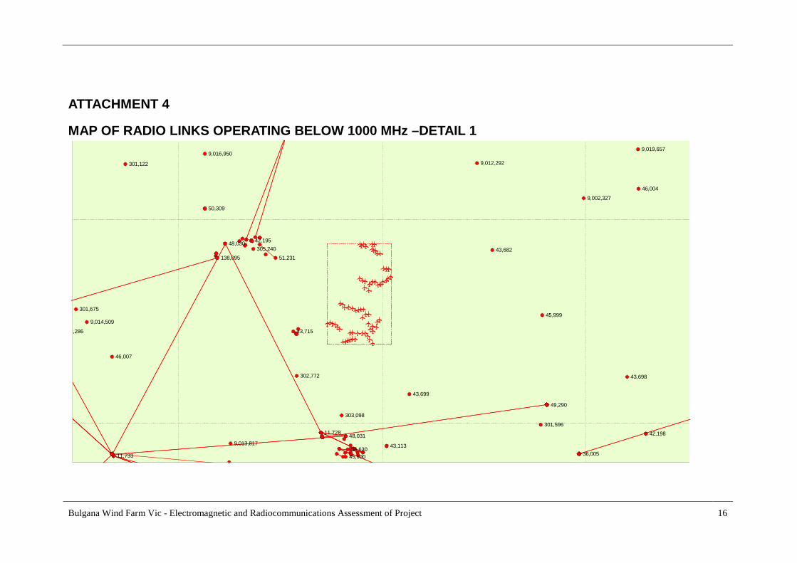
3 RADIO SERVICES LOCATED NEAR BULGANA WFFrom the latest ACMA database, maps have been prepared showing registered radio sites and point-to-point links in the locality of the Project site. Attachment 3 shows the situation for systems withfrequencies below 1000 MHz with a zoomed view in Attachment 4. Attachment 5 shows the links andsites for systems operating on frequencies above 1000 MHz with zoomed views in Attachments 6, 7, 8,and 9. Typical calculations of required clearances are shown in Attachment 10 using the formulas inBacon’s paper (Reference 1). It should be noted that site numbers displayed in Attachments 3 and 5may not be the actual ones associated with a particular point to point links due to label overlap of closespaced site labels.
3.1 Point-to-point SystemsThe radio link maps have been examined and the links crossing the wind farm site and near radio siteshave been identified from the ACMA data. There are 2 point-to-point links in the microwave bandsoperated by 2 operators over paths which nominally cross or are adjacent to the site. A number of radiosites which are located outside the wind farm boundaries but are close enough to be considered from abuffer zone point of view have also been examined. A summary of the calculated 2nd Fresnel zoneclearances at mid-path and at 1 km are shown in Table 1. No radio sites located within the wind farmboundaries were identified from an analysis of the ACMA data. There are no UHF links which cross orare close to the wind farm boundaries. The locations of the turbines have been shown in the link mapsgenerated in MapInfo and were used to confirm that distances from radio link ray lines and the turbinetower centrelines meet the clearance criteria.
TABLE 1 - MICROWAVE LINK CLEARANCES
PATH ACMASite ID’s
Total PathDist. km
FrequencyMHz
Operator Mid Path2nd FresnelZoneDistance m
1 Km FresnelZone Distancem
51170 - 300696 41.41 7500 Vodafone 28.8 8.8
51170 - 133134 12.68 11000 NBN Co 13.1 7.1
The calculation of the reflection/scattering zone using Bacon’s formula (Reference 1) requires iterationwith increasing values of the distance from the path bore sight at each distance from the terminal untilthe required C/I value is reached. As the recommended clearance distances above are calculated for themid path for each link (where the clearances are at a maximum) scattering from turbines near a radiosite will be low.
Bulgana Wind Farm Vic - Electromagnetic and Radiocommunications Assessment of Project 4
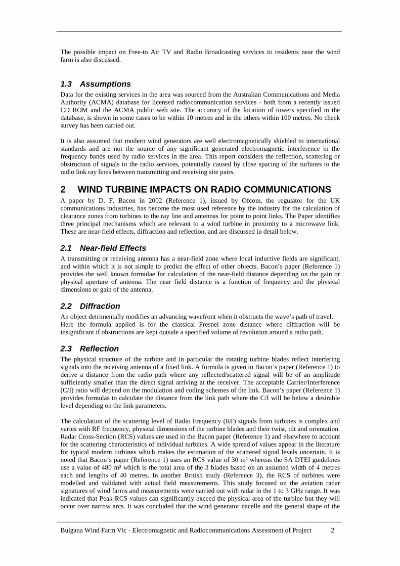
3.2 Off-Air Links to TV and FM Broadcasting Stations at Halls Gap,Ararat and Stawell.
Nearby low power TV and FM Broadcasting stations for towns in the general area are located at sitesas shown in Table 2 below:
TABLE 2 – LOCAL TV AND SOUND BROADCAST STATIONS
Town Site ID Type Distance to nearestWT km
Halls Gaps 36653 TV 30.2
Ararat 11729, 51170 FM 12.0, 13.3
Stawell 51170 FM 13.3
The nearest of these broadcasting sites is about 12 km from the closest turbines. All listed sites areseparated from the wind farm by sufficient distances to not have their TV or FM coverage impacted bywind turbines. From some past special purpose ACMA data it appears that the Halls Gap (Mt William)station receives TV main stations signals off-air from the Ballarat main TV station. Examination of thesignal path between the Ballarat main station and this repeater indicates that the path is sufficientlyclear of turbines to not cause any turbine disturbance of the input signals.
3.3 Air Services FacilitiesThe nearest Aerodrome is at Stawell. There are no registered Air Services Radar sites within line of siteof the turbines. VHF Ground – Air services are located at site 901800 (Mt William), 135871, 9013416and 909447 for AirServices Australia, Ararat Hospital, North Grampian shire and Department ofEnvironment and Primary Industries. Due to the separation distance between the wind farm boundariesand these sites of 12.5km or more and the nature of the services operated, no additional buffer zonesare required
3.4 Point to Multipoint (PMP) ServicesTable 3 lists sites within the Study area which are specified as point to multipoint services. Usuallyonly the base stations are ACMA registered for PMP systems, so the remote (subscriber or device) endis not known. It is therefore not possible to determine if there could be any turbine obstruction in thepaths between the base and the fixed remote end.
TABLE 3 - POINT TO MULTIPONT SYSTEMS IN THE AREA
Site/Service Frequency BandMHz
Operator Comment
302772, 11734,11733 450 Grampians W. M.Water
UHF
9019657, 305839,404211, 9012292,304776
450 Central HighlandsWater
UHF
305839, 304776 450 Stawell Gold Mines UHF
300696 1800 Aussie Broadband Microwave
133134 2300 NBN Co Microwave
Given that most base station locations are remote from the wind farm site there is a low probability thatany path to the remote (subscriber or device) would cross the wind farm. The NBN PMP licences arerecent and the site 133134 is about 3.99 km from the nearest turbine. There is some possibility that anyNBN customers to the East of the site could have their broadband services affected by turbines. Itwould be prudent to advise NBN and the other operators of the PMP Services of the wind farmproposal.
Bulgana Wind Farm Vic - Electromagnetic and Radiocommunications Assessment of Project 5
3.5 Bureau Of Meteorology Weather RadarThere are no listed weather radar sites within the study area of 50 km the wind farm and therefore noimpacts on these facilities are expected.
3.6 Radio Sites in Close Proximity to Wind TurbinesThere are no radio sites within the Project site. Sites external to the wind farm have been consideredbased on the nature of the radio service and the distance from the nearest turbines. Apart from point topoint radio systems shown in Attachments 3 and 5, a number of services including point to multipointand mobile radio base stations including cellular mobile base stations operated by Telstra, Optus andVodafone exist. There a number of CFA VHF base stations also in the area. All of the services havebeen examined for any possible impacts of wind turbines located 4km and beyond from the radio sites.Near-field calculations for the worst case point to point antennas have also been calculated. The worstcase microwave system (6.7 GHz, 3.0 metre parabolic antenna) has a near field of approx. 600 metres.Based on SA - GRN requirements for a Paging service, however, the NSW RFS paging service wouldrequire a buffer zone of 1000 metres. It is believed that a clearance of 1000 metres would also beadequate for the mobile base stations. The current spacing to the nearest turbine of 3.7 km would havenegligible effects on all services operating from the sites surrounding the turbines.
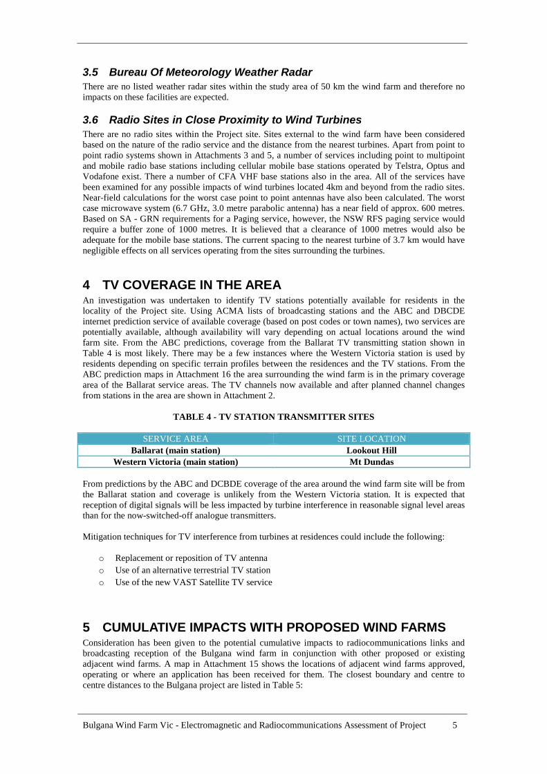
4 TV COVERAGE IN THE AREAAn investigation was undertaken to identify TV stations potentially available for residents in thelocality of the Project site. Using ACMA lists of broadcasting stations and the ABC and DBCDEinternet prediction service of available coverage (based on post codes or town names), two services arepotentially available, although availability will vary depending on actual locations around the windfarm site. From the ABC predictions, coverage from the Ballarat TV transmitting station shown inTable 4 is most likely. There may be a few instances where the Western Victoria station is used byresidents depending on specific terrain profiles between the residences and the TV stations. From theABC prediction maps in Attachment 16 the area surrounding the wind farm is in the primary coveragearea of the Ballarat service areas. The TV channels now available and after planned channel changesfrom stations in the area are shown in Attachment 2.
TABLE 4 - TV STATION TRANSMITTER SITES
SERVICE AREA SITE LOCATION
Ballarat (main station) Lookout Hill
Western Victoria (main station) Mt Dundas
From predictions by the ABC and DCBDE coverage of the area around the wind farm site will be fromthe Ballarat station and coverage is unlikely from the Western Victoria station. It is expected thatreception of digital signals will be less impacted by turbine interference in reasonable signal level areasthan for the now-switched-off analogue transmitters.
Mitigation techniques for TV interference from turbines at residences could include the following:
o Replacement or reposition of TV antenna
o Use of an alternative terrestrial TV station
o Use of the new VAST Satellite TV service
5 CUMULATIVE IMPACTS WITH PROPOSED WIND FARMSConsideration has been given to the potential cumulative impacts to radiocommunications links andbroadcasting reception of the Bulgana wind farm in conjunction with other proposed or existingadjacent wind farms. A map in Attachment 15 shows the locations of adjacent wind farms approved,operating or where an application has been received for them. The closest boundary and centre tocentre distances to the Bulgana project are listed in Table 5:
Bulgana Wind Farm Vic - Electromagnetic and Radiocommunications Assessment of Project 6
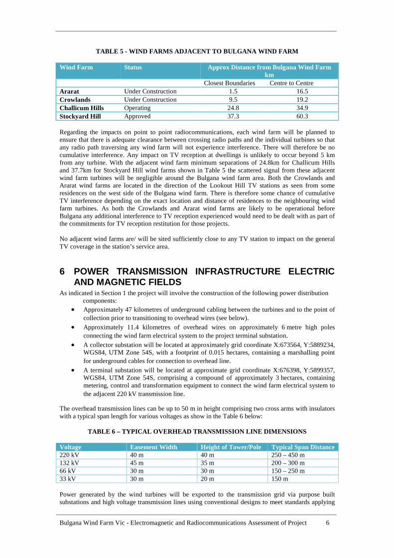
TABLE 5 - WIND FARMS ADJACENT TO BULGANA WIND FARM
Wind Farm Status Approx Distance from Bulgana Wind Farmkm
Closest Boundaries Centre to Centre
Ararat Under Construction 1.5 16.5
Crowlands Under Construction 9.5 19.2
Challicum Hills Operating 24.8 34.9
Stockyard Hill Approved 37.3 60.3
Regarding the impacts on point to point radiocommunications, each wind farm will be planned toensure that there is adequate clearance between crossing radio paths and the individual turbines so thatany radio path traversing any wind farm will not experience interference. There will therefore be nocumulative interference. Any impact on TV reception at dwellings is unlikely to occur beyond 5 kmfrom any turbine. With the adjacent wind farm minimum separations of 24.8km for Challicum Hillsand 37.7km for Stockyard Hill wind farms shown in Table 5 the scattered signal from these adjacentwind farm turbines will be negligible around the Bulgana wind farm area. Both the Crowlands andArarat wind farms are located in the direction of the Lookout Hill TV stations as seen from someresidences on the west side of the Bulgana wind farm. There is therefore some chance of cumulativeTV interference depending on the exact location and distance of residences to the neighbouring windfarm turbines. As both the Crowlands and Ararat wind farms are likely to be operational beforeBulgana any additional interference to TV reception experienced would need to be dealt with as part ofthe commitments for TV reception restitution for those projects.
No adjacent wind farms are/ will be sited sufficiently close to any TV station to impact on the generalTV coverage in the station’s service area.
6 POWER TRANSMISSION INFRASTRUCTURE ELECTRICAND MAGNETIC FIELDS
As indicated in Section 1 the project will involve the construction of the following power distributioncomponents:
Approximately 47 kilometres of underground cabling between the turbines and to the point of
collection prior to transitioning to overhead wires (see below).
Approximately 11.4 kilometres of overhead wires on approximately 6 metre high poles
connecting the wind farm electrical system to the project terminal substation.
A collector substation will be located at approximately grid coordinate X:673564, Y:5889234,WGS84, UTM Zone 54S, with a footprint of 0.015 hectares, containing a marshalling point
for underground cables for connection to overhead line.
A terminal substation will be located at approximate grid coordinate X:676398, Y:5899357,WGS84, UTM Zone 54S, comprising a compound of approximately 3 hectares, containingmetering, control and transformation equipment to connect the wind farm electrical system to
the adjacent 220 kV transmission line.
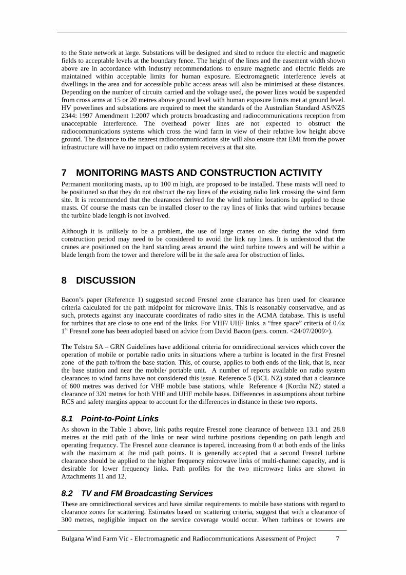
The overhead transmission lines can be up to 50 m in height comprising two cross arms with insulatorswith a typical span length for various voltages as show in the Table 6 below:
TABLE 6 – TYPICAL OVERHEAD TRANSMISSION LINE DIMENSIONS
Voltage Easement Width Height of Tower/Pole Typical Span Distance220 kV 40 m 40 m 250 – 450 m132 kV 45 m 35 m 200 – 300 m66 kV 30 m 30 m 150 – 250 m33 kV 30 m 20 m 150 m
Power generated by the wind turbines will be exported to the transmission grid via purpose builtsubstations and high voltage transmission lines using conventional designs to meet standards applying
Bulgana Wind Farm Vic - Electromagnetic and Radiocommunications Assessment of Project 7
to the State network at large. Substations will be designed and sited to reduce the electric and magneticfields to acceptable levels at the boundary fence. The height of the lines and the easement width shownabove are in accordance with industry recommendations to ensure magnetic and electric fields aremaintained within acceptable limits for human exposure. Electromagnetic interference levels atdwellings in the area and for accessible public access areas will also be minimised at these distances.Depending on the number of circuits carried and the voltage used, the power lines would be suspendedfrom cross arms at 15 or 20 metres above ground level with human exposure limits met at ground level.HV powerlines and substations are required to meet the standards of the Australian Standard AS/NZS2344: 1997 Amendment 1:2007 which protects broadcasting and radiocommunications reception fromunacceptable interference. The overhead power lines are not expected to obstruct theradiocommunications systems which cross the wind farm in view of their relative low height aboveground. The distance to the nearest radiocommunications site will also ensure that EMI from the powerinfrastructure will have no impact on radio system receivers at that site.
7 MONITORING MASTS AND CONSTRUCTION ACTIVITYPermanent monitoring masts, up to 100 m high, are proposed to be installed. These masts will need tobe positioned so that they do not obstruct the ray lines of the existing radio link crossing the wind farmsite. It is recommended that the clearances derived for the wind turbine locations be applied to thesemasts. Of course the masts can be installed closer to the ray lines of links that wind turbines becausethe turbine blade length is not involved.
Although it is unlikely to be a problem, the use of large cranes on site during the wind farmconstruction period may need to be considered to avoid the link ray lines. It is understood that thecranes are positioned on the hard standing areas around the wind turbine towers and will be within ablade length from the tower and therefore will be in the safe area for obstruction of links.
8 DISCUSSION
Bacon’s paper (Reference 1) suggested second Fresnel zone clearance has been used for clearancecriteria calculated for the path midpoint for microwave links. This is reasonably conservative, and assuch, protects against any inaccurate coordinates of radio sites in the ACMA database. This is usefulfor turbines that are close to one end of the links. For VHF/ UHF links, a “free space” criteria of 0.6x1st Fresnel zone has been adopted based on advice from David Bacon (pers. comm. <24/07/2009>).
The Telstra SA – GRN Guidelines have additional criteria for omnidirectional services which cover theoperation of mobile or portable radio units in situations where a turbine is located in the first Fresnelzone of the path to/from the base station. This, of course, applies to both ends of the link, that is, nearthe base station and near the mobile/ portable unit. A number of reports available on radio systemclearances to wind farms have not considered this issue. Reference 5 (BCL NZ) stated that a clearanceof 600 metres was derived for VHF mobile base stations, while Reference 4 (Kordia NZ) stated aclearance of 320 metres for both VHF and UHF mobile bases. Differences in assumptions about turbineRCS and safety margins appear to account for the differences in distance in these two reports.
8.1 Point-to-Point LinksAs shown in the Table 1 above, link paths require Fresnel zone clearance of between 13.1 and 28.8metres at the mid path of the links or near wind turbine positions depending on path length andoperating frequency. The Fresnel zone clearance is tapered, increasing from 0 at both ends of the linkswith the maximum at the mid path points. It is generally accepted that a second Fresnel turbineclearance should be applied to the higher frequency microwave links of multi-channel capacity, and isdesirable for lower frequency links. Path profiles for the two microwave links are shown inAttachments 11 and 12.
8.2 TV and FM Broadcasting ServicesThese are omnidirectional services and have similar requirements to mobile base stations with regard toclearance zones for scattering. Estimates based on scattering criteria, suggest that with a clearance of300 metres, negligible impact on the service coverage would occur. When turbines or towers are
Bulgana Wind Farm Vic - Electromagnetic and Radiocommunications Assessment of Project 8
closely placed to transmitters, there is also the possibility of impacts on TV reception, such as ghostingand other effects. These impacts may occur over a large area. However, as there is a considerabledistance to the nearest turbine, a negligible impact is expected upon local low power TV and FMstations mentioned above. There is still the potential, though, that TV reception from the main and localstation(s) may be impaired at some residences close to the turbines. References 6, 7, 8 and 9 providedetails of the mechanism and estimation of TV signal scattering from wind turbines. References 8 and9 are recent ITU documents which specifically address the issue of the impact of wind turbines ondigital television.
8.3 Mobile Radio Base StationsOnce again, the relevant criterion is the Scattering mechanism. Calculations for the Mobile and Pagingbase stations suggest a 200 metre clearance. The SA - GRN Guidelines (Reference 2), however,recommend buffer zones of 1200 metres for emergency services radio base stations and PagingServices.
9 RECOMMENDATIONS
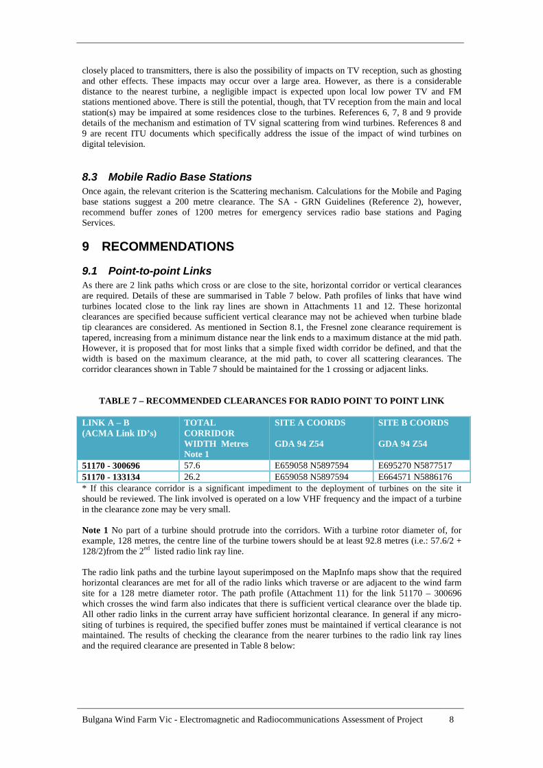
9.1 Point-to-point LinksAs there are 2 link paths which cross or are close to the site, horizontal corridor or vertical clearancesare required. Details of these are summarised in Table 7 below. Path profiles of links that have windturbines located close to the link ray lines are shown in Attachments 11 and 12. These horizontalclearances are specified because sufficient vertical clearance may not be achieved when turbine bladetip clearances are considered. As mentioned in Section 8.1, the Fresnel zone clearance requirement istapered, increasing from a minimum distance near the link ends to a maximum distance at the mid path.However, it is proposed that for most links that a simple fixed width corridor be defined, and that thewidth is based on the maximum clearance, at the mid path, to cover all scattering clearances. Thecorridor clearances shown in Table 7 should be maintained for the 1 crossing or adjacent links.
TABLE 7 – RECOMMENDED CLEARANCES FOR RADIO POINT TO POINT LINK
LINK A – B(ACMA Link ID’s)
TOTALCORRIDORWIDTH MetresNote 1
SITE A COORDS
GDA 94 Z54
SITE B COORDS
GDA 94 Z54
51170 - 300696 57.6 E659058 N5897594 E695270 N5877517
51170 - 133134 26.2 E659058 N5897594 E664571 N5886176
* If this clearance corridor is a significant impediment to the deployment of turbines on the site itshould be reviewed. The link involved is operated on a low VHF frequency and the impact of a turbinein the clearance zone may be very small.
Note 1 No part of a turbine should protrude into the corridors. With a turbine rotor diameter of, forexample, 128 metres, the centre line of the turbine towers should be at least 92.8 metres (i.e.: 57.6/2 +128/2)from the 2nd listed radio link ray line.
The radio link paths and the turbine layout superimposed on the MapInfo maps show that the requiredhorizontal clearances are met for all of the radio links which traverse or are adjacent to the wind farmsite for a 128 metre diameter rotor. The path profile (Attachment 11) for the link 51170 – 300696which crosses the wind farm also indicates that there is sufficient vertical clearance over the blade tip.All other radio links in the current array have sufficient horizontal clearance. In general if any micro-siting of turbines is required, the specified buffer zones must be maintained if vertical clearance is notmaintained. The results of checking the clearance from the nearer turbines to the radio link ray linesand the required clearance are presented in Table 8 below:

Bulgana Wind Farm Vic - Electromagnetic and Radiocommunications Assessment of Project 9
TABLE 8 - RADIO LINK CLEARANCE COMPLIANCE
Wind Turbine IDScaled Distance from MapInfo Calculated Required Clearance
BU-37 700m 92.8m
BU-40 930m 92.8m
BU-42 850m 92.8m
BU-48 3985m 77.1m
9.2 General Buffer Zones
Taking into account the scattering zone requirements of all omnidirectional services, and the near-fieldclearances required for the longer distance links, a clearance circle of 1200 metres radius (centred onthe radio towers) is the worst case zone requirement (worst case typical site see Attachment 10). Thisis based on the SA - GRN guidelines for emergency services omnidirectional services which includepaging services. All radio sites are at least 4000 metres from the nearest turbines in the current layoutso no buffer zones are required.
9.3 Interference to Television Reception
The Project site is in the Regional Victoria TV1 Licence area. The Ballarat and Western Victoria maintelevision stations at Lookout Hill and Mt Dundas would generally service the area, with transmissionfrom lower power translator stations at Halls Gap.
The prediction of TV interference at individual dwellings as a result of turbine interference has beenshown to be generally unreliable. As indicated in Reference 7, there is a possibility that interference toTV reception at some residences that are particularly close to turbines may occur (if they are located inthe forward scatter zone, in the received direction of the TV stations). It is expected that reception ofdigital signals will be less impacted by turbine interference in reasonably high signal level areas. Basedon experience in areas surrounding operational wind farms in Victoria and elsewhere there is somepossibility that TV reception at some dwellings west of the Bulgana wind farm and within about 5kmof wind turbines could be affected. Where residents’ TV antennas are directed towards wind turbines inthe path to Lookout Hill some interference could be experienced. The location of dwellings around thewind farm are shown in a map in Attachment 14. A number of possible mitigation methods areavailable to restore interference-free television to dwellings as listed in Section 4.
Television operators in the area are:
Broadcast Australia – ABC and SBS Southern Cross Ten Prime Television (Southern) Pty Ltd WIN Television Vic Pty Ltd
It is recommended that these organisations and Broadcast Australia, who own and operate the ABC,SBS and shared commercial transmission facilities, be advised of the wind farm proposal and berequested to comment on any issues they have from a TV coverage impact point of view.
9.4 Interference to Radio ReceptionInterference to AM radio reception is highly unlikely due to the propagation mechanism involved. Noreported interference overseas or in Australia has been reported. FM radio reception interference, whiletheoretically possible, also has not been observed except in laboratory set-ups. It is therefore concludedthat impairment of AM and FM radio reception around the proposed wind farm is highly unlikely.
Bulgana Wind Farm Vic - Electromagnetic and Radiocommunications Assessment of Project 10
10 CONCLUSIONSFor the current layout of wind turbines no adverse impacts on point to point or omnidirectional radiosystems in the area are expected.
TV and radio broadcasting transmitting sites are sufficiently distant from turbines to not have anygeneral service area coverage degradation.
Some individual dwellings close to turbines and in the forward scatter areas of TV transmissions mayexperience some reception impairment. However mitigation methods are available to return receptionto at least preconstruction conditions.
Interconnecting power lines and substations will be constructed and located according to industrystandards to ensure that magnetic and electric fields are well below the human exposure limits forpublic spaces and at private dwellings. EMI levels at power line easement boundaries will be requiredto meet the appropriate Australian Standard levels which will ensure that radio and TV reception andother radiocommunication services will not be impaired.
Bulgana Wind Farm Vic - Electromagnetic and Radiocommunications Assessment of Project 11
11 REFERENCES
[1] Fixed-Link wind-turbine exclusion zone method, Version 1.1, 28 October 2002, D.F. Bacon, UKRadio Communications Agency,
[2] Guidelines for Minimizing the Impact of Wind Farms on the SA - GRN, Issue 1, 22 October 2003,Rohan Fernandez, Telstra SA, Document TR049-SA
[3] Wind Farms Impact on Radar Aviation Interests-Final Report, September 2003, FESW/14/00614/00/REP, Contractor QinetiQ Prepared by Gavin J Poupart.
[4] Mahinerangi Wind Farm, Compatibility with Radio Services, 3 April 2007, Anton Pereira &Richard Brown, Kordia NZ
[5] Project Hayes, Compatibility with Radio Services, 7 July 2006, Duncan Chisholm, BCL NZ
[6] Electromagnetic Interference from Wind Turbines, Sengupta & Senior, Chapter 9, Wind TurbineTechnology Ed. David E. Spera ASME Press 1994
[7] ITU, ITU-R Recommendation BT805 Assessment of Impairment Caused to Television Receptionby a Wind Turbine 1992
[8] ITU, ITU-R, Recommendation BT.1893 Assessment of Impairment Caused to Digital TelevisionReception by a Wind Turbine May 2011
[9] ITU, ITU-R, Report BT.2142-1 The Effect of the Scattering of Digital Television Signals from aWind Turbine

Bulgana Wind Farm Vic - Electromagnetic and Radiocommunications Assessment of Project 12
ATTACHMENT 1
WIND TURBINE GRID COORDINATES BULGANA WIND FARMZONE 54 MGA94
ID ID2 E N
1 BU_01 672343.9572 5897186.573
2 BU_02 672565.7095 5897026.728
3 BU_03 672836.1798 5897170.104
4 BU_04 673070.8035 5896900.578
5 BU_05 673799.8763 5897149.08
6 BU_06 674135.4181 5897196.444
7 BU_07 673834.2676 5896560.241
8 BU_08 674059.2189 5896418.7
9 BU_09 674327.5896 5896365.176
10 BU_10 674489.779 5896039.684
11 BU_11 674818.2303 5896039.048
12 BU_12 675200.6046 5894203.767
13 BU_13 675556.1969 5894170.302
14 BU_14 675892.1969 5894170.302
15 BU_15 672277.2299 5892970.281
16 BU_16 672660.8256 5892685.06
17 BU_17 672992.3919 5892663.98
18 BU_18 673510.6025 5892255.614
19 BU_19 673813.0271 5892560.59
20 BU_20 674176.9699 5892566.459
21 BU_21 674581.7723 5892195.911
22 BU_22 674862.8482 5892271.289
23 BU_23 675143.2035 5892601.75
24 BU_24 675563.3605 5892706.338
25 BU_25 675845.4561 5892932.144
26 BU_26 676149.0611 5893170.23
27 BU_27 672933.8967 5891851.344
28 BU_28 673423.8325 5891484.127
29 BU_29 669916.0285 5889919.012
30 BU_30 670218.0756 5889771.826
31 BU_31 670485.6122 5889421.97
32 BU_32 670947.1451 5889462.754
33 BU_33 671476.4999 5889305
34 BU_34 671870.7105 5889006.928
35 BU_35 672176.5597 5889133.039
36 BU_36 672493.6242 5889172.726
37 BU_37 672779.1989 5889186.152
38 BU_38 672683.8998 5888140.915
39 BU_39 673119.4179 5888566.648
40 BU_40 673432.2447 5888560.179
41 BU_41 674502.7933 5887683
Bulgana Wind Farm Vic - Electromagnetic and Radiocommunications Assessment of Project 13
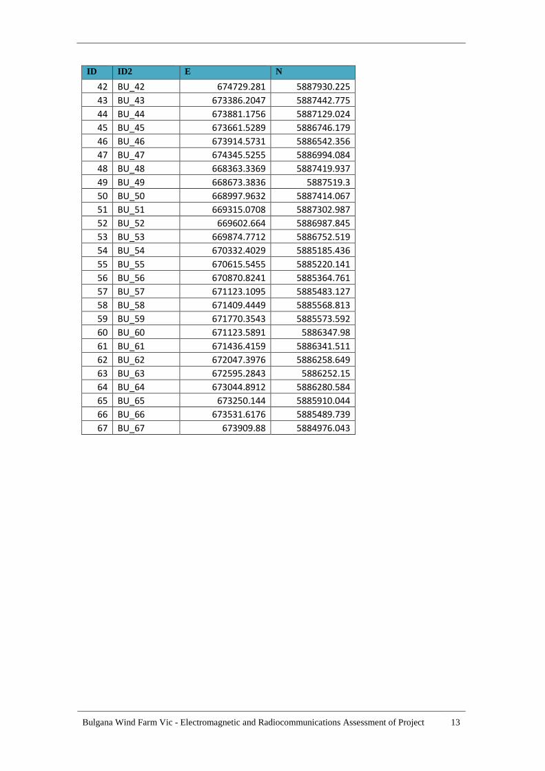
ID ID2 E N
42 BU_42 674729.281 5887930.225
43 BU_43 673386.2047 5887442.775
44 BU_44 673881.1756 5887129.024
45 BU_45 673661.5289 5886746.179
46 BU_46 673914.5731 5886542.356
47 BU_47 674345.5255 5886994.084
48 BU_48 668363.3369 5887419.937
49 BU_49 668673.3836 5887519.3
50 BU_50 668997.9632 5887414.067
51 BU_51 669315.0708 5887302.987
52 BU_52 669602.664 5886987.845
53 BU_53 669874.7712 5886752.519
54 BU_54 670332.4029 5885185.436
55 BU_55 670615.5455 5885220.141
56 BU_56 670870.8241 5885364.761
57 BU_57 671123.1095 5885483.127
58 BU_58 671409.4449 5885568.813
59 BU_59 671770.3543 5885573.592
60 BU_60 671123.5891 5886347.98
61 BU_61 671436.4159 5886341.511
62 BU_62 672047.3976 5886258.649
63 BU_63 672595.2843 5886252.15
64 BU_64 673044.8912 5886280.584
65 BU_65 673250.144 5885910.044
66 BU_66 673531.6176 5885489.739
67 BU_67 673909.88 5884976.043

Bulgana Wind Farm Vic - Electromagnetic and Radiocommunications Assessment of Project 14
ATTACHMENT 2 - TELEVISION STATIONS & CHANNELS -BULGANA WIND FARM AREA
TransmitterLocation/service
Operator Current DigitalChannels
*RetunedDigitalChannels
Comment
Lookout HillBallarat
SBS 43H 34H UHF
ABC 41H 35H UHF
PRIME 46H 36H UHF
S/C 40H 38H UHF
WIN 37H 37H UHF
Mt DundasWestern Victoria
SBS 7H 7H VHF
ABC 6H 6H VHF
PRIME 12H 12H VHF
S/C 11H 11H VHF
WIN 10H 10H VHF
*Ballarat - 17/09/2014 switch over date as part of the channel retune processcurrently underway in Australia.

Bulgana Wind Farm Vic - Electromagnetic and Radiocommunications Assessment of Project 15
ATTACHMENT 3
MAP OF RADIO LINKS & SITES OPERATING BELOW 1000MHz
Map shown on following page

0 12.5 25
kilometres
5925000m N5925000m N5925000m N5925000m N5925000m N5925000m N5925000m N5925000m N5925000m N
5875000m N5875000m N5875000m N5875000m N5875000m N5875000m N5875000m N5875000m N5875000m N
5900000m N5900000m N5900000m N5900000m N5900000m N5900000m N5900000m N5900000m N5900000m N
5825000m N5825000m N5825000m N5825000m N5825000m N5825000m N5825000m N5825000m N5825000m N
5850000m N5850000m N5850000m N5850000m N5850000m N5850000m N5850000m N5850000m N5850000m N
5950000m N5950000m N5950000m N5950000m N5950000m N5950000m N5950000m N5950000m N5950000m N
60
00
00
mE
60
00
00
mE
60
00
00
mE
60
00
00
mE
60
00
00
mE
60
00
00
mE
60
00
00
mE
60
00
00
mE
60
00
00
mE
62
50
00
mE
62
50
00
mE
62
50
00
mE
62
50
00
mE
62
50
00
mE
62
50
00
mE
62
50
00
mE
62
50
00
mE
62
50
00
mE
65
00
00
mE
65
00
00
mE
65
00
00
mE
65
00
00
mE
65
00
00
mE
65
00
00
mE
65
00
00
mE
65
00
00
mE
65
00
00
mE
75
00
00
mE
75
00
00
mE
75
00
00
mE
75
00
00
mE
75
00
00
mE
75
00
00
mE
75
00
00
mE
75
00
00
mE
75
00
00
mE
72
50
00
mE
72
50
00
mE
72
50
00
mE
72
50
00
mE
72
50
00
mE
72
50
00
mE
72
50
00
mE
72
50
00
mE
72
50
00
mE
70
00
00
mE
70
00
00
mE
70
00
00
mE
70
00
00
mE
70
00
00
mE
70
00
00
mE
70
00
00
mE
70
00
00
mE
70
00
00
mE
67
50
00
mE
67
50
00
mE
67
50
00
mE
67
50
00
mE
67
50
00
mE
67
50
00
mE
67
50
00
mE
67
50
00
mE
67
50
00
mE
5800000m N5800000m N5800000m N5800000m N5800000m N5800000m N5800000m N5800000m N5800000m N
5975000m N5975000m N5975000m N5975000m N5975000m N5975000m N5975000m N5975000m N5975000m N
11,72811,733 36,005
36,454
36,791
36,944
38,035
42,168
42,195
42,19843,113
43,617
43,645
43,680
43,682
43,69843,699
43,715
45,992
45,997
45,999
46,003
46,004
46,006
46,007
46,00846,375
49,290
50,309
133,155
301,122
301,675
302,772
306,085
9,008,714
9,012,2929,016,950 9,019,657
Postal: P.O. Box 3213, BELCONNEN ACT 2617Telephone: 02 6253 2555Facsimile: 02 6253 2800
TITLE:
40-999 MHz AssignmentsAs Extracted from RRL Database
FILENAME:40-999 MHz Bulgana Wind Farm
PROJECT:Bulgana Wind Farm
DRWG NO:1
DATE:13/8/2014
SCALE:N/A
BY:SEA
Bulgana Wind Farm Vic - Electromagnetic and Radiocommunications Assessment of Project 16
ATTACHMENT 4
MAP OF RADIO LINKS OPERATING BELOW 1000 MHz –DETAIL 1
11,728
11,733 36,00536,630
36,944
42,195
42,198
42,286
43,113
43,682
43,698
43,699
43,715
45,990
45,999
46,004
46,007
48,030
48,031
49,290
50,309
51,231138,095
301,122
301,596
301,675
302,772
303,098
305,240
9,002,327
9,012,292
9,013,817
9,014,509
9,016,9509,019,657
Bulgana Wind Farm Vic - Electromagnetic and Radiocommunications Assessment of Project 17
ATTACHMENT 5
MAP OF RADIO LINKS & SITES OPERATING ABOVE 1000 MHz
Map shown on following page

0 12.5 25
kilometres
5925000m N5925000m N5925000m N5925000m N5925000m N5925000m N5925000m N5925000m N5925000m N
5875000m N5875000m N5875000m N5875000m N5875000m N5875000m N5875000m N5875000m N5875000m N
5900000m N5900000m N5900000m N5900000m N5900000m N5900000m N5900000m N5900000m N5900000m N
5825000m N5825000m N5825000m N5825000m N5825000m N5825000m N5825000m N5825000m N5825000m N
5850000m N5850000m N5850000m N5850000m N5850000m N5850000m N5850000m N5850000m N5850000m N
5950000m N5950000m N5950000m N5950000m N5950000m N5950000m N5950000m N5950000m N5950000m N
60
00
00
mE
60
00
00
mE
60
00
00
mE
60
00
00
mE
60
00
00
mE
60
00
00
mE
60
00
00
mE
60
00
00
mE
60
00
00
mE
62
50
00
mE
62
50
00
mE
62
50
00
mE
62
50
00
mE
62
50
00
mE
62
50
00
mE
62
50
00
mE
62
50
00
mE
62
50
00
mE
65
00
00
mE
65
00
00
mE
65
00
00
mE
65
00
00
mE
65
00
00
mE
65
00
00
mE
65
00
00
mE
65
00
00
mE
65
00
00
mE
75
00
00
mE
75
00
00
mE
75
00
00
mE
75
00
00
mE
75
00
00
mE
75
00
00
mE
75
00
00
mE
75
00
00
mE
75
00
00
mE
72
50
00
mE
72
50
00
mE
72
50
00
mE
72
50
00
mE
72
50
00
mE
72
50
00
mE
72
50
00
mE
72
50
00
mE
72
50
00
mE
70
00
00
mE
70
00
00
mE
70
00
00
mE
70
00
00
mE
70
00
00
mE
70
00
00
mE
70
00
00
mE
70
00
00
mE
70
00
00
mE
67
50
00
mE
67
50
00
mE
67
50
00
mE
67
50
00
mE
67
50
00
mE
67
50
00
mE
67
50
00
mE
67
50
00
mE
67
50
00
mE
5800000m N5800000m N5800000m N5800000m N5800000m N5800000m N5800000m N5800000m N5800000m N
5975000m N5975000m N5975000m N5975000m N5975000m N5975000m N5975000m N5975000m N5975000m N
9,013,218
9,013,817
9,021,284
9,021,285
9,021,286
11,72911,733 36,005
36,007
36,214
36,754
36,791
49,290
50,309
51,170
131,901
132,291
133,134
133,155
204,824
300,263
300,672
300,697
301,122
301,196
304,278
304,700
304,769
305,343
305,790
9,011,539
Postal: P.O. Box 3213, BELCONNEN ACT 2617Telephone: 02 6253 2555Facsimile: 02 6253 2800
TITLE:
Above 1 GHz AssignmentsAs Extracted from RRL Database
FILENAME:Above 1 GHz Bulgana Wind Farm
PROJECT:Bulgana Wind Farm
DRWG NO:2
DATE:13/8/2014
SCALE:N/A
BY:SEA

Bulgana Wind Farm Vic - Electromagnetic and Radiocommunications Assessment of Project 18
ATTACHMENT 6
MAP OF RADIO LINKS OPERATING ABOVE 1000 MHz – DETAIL 1
9,013,817
9,021,285
11,728
11,733 36,00536,630
49,290
50,309
51,170
133,134
301,122
301,196
Bulgana Wind Farm Vic - Electromagnetic and Radiocommunications Assessment of Project 19
ATTACHMENT 7
MAP OF RADIO LINKS OPERATING ABOVE 1000 MHz – DETAIL 2
BU_18BU_21
BU_27
BU_28
BU_29
BU_30
BU_31 BU_32
BU_33
BU_34
BU_35BU_36
BU_38
BU_39 BU_40
BU_41
BU_42
BU_43BU_48BU_49
Bulgana Wind Farm Vic - Electromagnetic and Radiocommunications Assessment of Project 20
ATTACHMENT 8
MAP OF RADIO LINKS OPERATING ABOVE 1000 MHz – DETAIL 3
BU_33
BU_34
BU_35BU_36 BU_37
BU_38
BU_39 BU_40
BU_41
BU_42
BU_43

Bulgana Wind Farm Vic - Electromagnetic and Radiocommunications Assessment of Project 21
ATTACHMENT 9
MAP OF RADIO LINKS OPERATING ABOVE 1000 MHz – DETAIL 4BU_33
BU_34
BU_48BU_49
BU_50BU_51
BU_52
BU_53
BU_54
BU_56
BU_57BU_59
BU_60 BU_61
133,134

Bulgana Wind Farm Vic - Electromagnetic and Radiocommunications Assessment of Project 22
ATTACHMENT 10
SAMPLE CALCULATIONS OF CLEARANCE ZONES
The calculations below are examples for near field, second Fresnel zone and scattering clearances forthe point-to-point and omnidirectional services. The results of all calculations are in tables in the bodyof the Assessment. The formulas used are taken from Reference 1
1. Point-to-point Link 55450 to 6909 TransGrid
(a) Near Field ZoneFrequency 45 MHzAntenna Gain 8.2 dB
Dnf = 0.1 100.1G / f= 0.1x 100.1 x 8.2 /0.045= 14.7 metres
Second Fresnel ClearancePath Distance 119kmMid Path distance 59.5km
21
212F
dd
dd2R
= 119000/5950059500)45/300(2 xxx
....=630. metres (mid path)
= 119000/1180001000)45/300(2 xxx= 115 metres @ 1km from tower
(b) Reflection/Scattering Clearance Zone
The ratio, expressed in dB, of the wanted signal level received from the direct T-R path divided by theworst-case signal level received from the indirect T-W-R path, is given by:
Rci = 71 + S + 20 log (s1 s2) - 20 log (Dp) + G1(0) + G2(0) - G1(1) - G2(2) (dB)where:
s1, 2 = (km)
S = 10 log( ) (dB) = Worst-case radar cross section of turbine (m2)
G1, 2 (0) = Antenna boresight gains (dBi)G1, 2 (1, 2) = Antenna gain at off-boresight angles (dBi)
1, 2 = angle ( Ds , d1, 2 )
For each pair of d1, 2 values, equations above are used to evaluate Rci for Ds incremented from zero(from a non-zero but small distance in the vicinity of the terminals) upwards in suitably smallincrements until the required value of C/I ratio, given by Rci, is obtained. A guide as to a suitableincrement for Ds is that the resulting zone should be defined by a smooth curve.
Antenna Type Scalar Y103 – 203 VertTurbine Radar Cross Section (RCS) assumed 1000 metres²
22
21, sDd

Bulgana Wind Farm Vic - Electromagnetic and Radiocommunications Assessment of Project 23
C/I Ratio required >40dB
An Excel spread sheet was set up to with the formulas above implemented to carry out the iterationrequired for d1, d2 values for increasing values of Ds. At 1.0km from the tower a C/I value of 40 dB wasachieved at <100 metres off the rayline. Beyond 1 km the C/I value is achieved even on boresight.These indicates that scattering can be ignored 1 km and beyond the end sites. The published RadiationPattern Envelope (RPE) for the antenna types for the actual link was used in the calculation
2. Telstra Point to Multipoint Radio Base Stations – Omnidirectional Coverage
(a) Near Field ZoneFrequency 3.4 GHzAntenna Gain 10dB
Dnf = 0.1 100.1G / f= 0.1x 100.1x10 /3.4= 0.3 metres
(b) Reflection/Scattering Clearance ZoneTurbine RCS = 1000 m²Wanted C/I >30dB
The C/I ratio is:
)()(
)0()0(4
2211
2
21
2
2
2
1
ggD
ggss
l
lr
pd
ici
For the omnidirectional case g1(0) = g1( ) & g2(0) = g2( )It can also be assumed that S1 will approx equal Dp
then
224 S
l
lr
d
ici
= 4x x 300²/1000=1130 or 30.5dB at 300 metres
Bulgana Wind Farm Vic - Electromagnetic and Radiocommunications Assessment of Project 24
ATTACHMENT 11 – VODAFONE LINK PATH PROFILE SITE 51170 to SITE 300696
Vodafone Microwave Link
Positions of Closest 196m Turbines Shown.
Feb 10 14
Lawrence Derrick& Associates
51170
Latitude 37 03 15.92 SLongitude 142 47 19.84 E
Azimuth 117.92°Elevation 297 m ASLAntenna CL 5.0 m AGL
300696
Latitude 37 13 42.34 SLongitude 143 12 03.93 E
Azimuth 297.68°Elevation 869 m ASLAntenna CL 50.0 m AGL
Frequency(MHz) = 7500.0K = 1.33
Fn = 1.00, 2.00
Elevation
(m)
200
300
400
500
600
700
800
900
Path length (41.41 km)
05 10 15 20 25 30 35
40

Bulgana Wind Farm Vic - Electromagnetic and Radiocommunications Assessment of Project 25
ATTACHMENT 12 – NBN CO. LINK PATH PROFILE SITE 51170 to SITE 133134
NBN Co. Microwave Link Feb 10 14
Lawrence Derrick& Associates
51170
Latitude 37 03 15.92 SLongitude 142 47 19.84 EAzimuth 153.15°Elevation 297 m ASL
Antenna CL 20.0 m AGL
133134
Latitude 37 09 22.83 SLongitude 142 51 11.96 EAzimuth 333.11°Elevation 253 m ASL
Antenna CL 22.0 m AGL
Frequency(MHz) = 11000.0K = 1.33
Fn = 1.00, 2.00
Elevation(m
)
220
230
240
250
260
270
280
290
300
310
Path length (12.68 km)
0 1 2 3 4 5 6 7 8 9 10 11 12
Bulgana Wind Farm Vic - Electromagnetic and Radiocommunications Assessment of Project 26
ATTACHMENT 13
BULGANA WIND FARM SITE LAYOUT

Bulgana Wind Farm Vic - Electromagnetic and Radiocommunications Assessment of Project 27
ATTACHMENT 14
BULGANA WIND FARM SITE - DWELLINGS WITHIN 5KM

Bulgana Wind Farm Vic - Electromagnetic and Radiocommunications Assessment of Project 28
ATTACHMENT 15
MAP OF WIND FARMS ADJACENT TO BULGANA WIND FARM

Bulgana Wind Farm Vic - Electromagnetic and Radiocommunications Assessment of Project 29
ATTACHMENT 16– ABC PREDICTED TV COVERAGE FORMAIN STATIONS AT LOOKOUT HILL AND MT DUNDAS
BALLARAT
WESTERN VICTORIA
Transmitter Icon - BlueBulgana Wind Farm Location Icon - Orange