attachment 7 of form c-137 facility design and...
TRANSCRIPT
ATTACHMENT 7 OF
FORM C-137
FACILITY DESIGN AND CONSTRUCTION
'OIL CONSthViUiGN OM.-SANTA FE, NEW MEfou.-
•RASE EXHiBiT No._
% .i> o
03IX3W t m '3.3 ViSiV MdSSIWWOO NOJIVAH-J'SMO:
3HJ, 3H0J3a


2 i
iirrooi aaawriN iDjrobd s«?i 7«o *f**r; vo and ovo«in*

<J V)
ij ui * - > o ? O «
a;
<0
1 1
ticroot b3flnrw i03rontj "

FINAL Ciandv Marley Inc., Commercial Lamlhum
CLAY LINER
MATERIALS
A. Clay liner material shall be obtained from borrow areas or stockpiles identified by the Owner.
B. Clay liner material for landfill or surface impoundment construction shall:
\. Be classified according to the Unified Soil Classification System (USCS) as CL or CH (ASTM D 2487) and exhibit a minimum liquid limit of 30 and a minimum plasticity index of 11.
2. Have a percentage of gravel (i.e., dry weight retained on a U.S. No. 4 sieve) of less than 15 percent.
3. Have particles no larger than 2 inches (in largest dimension) after processing but prior to placement and no larger than 1 inch (in largest dimension) after placement and compaction.
4. Have a hydraulic conductivity of not more than 1 x 10 7 cm/scc when compacted in accordance with these General Specifications and tested in the laboratory in accordance with ASTM D 5084 at an average effective confining pressure of 5 psi.
CLAY LINER COMPACTION
A. Clay liner be compacted to a minimum of 90% of thc materials maximum dry density as determined by ASTM D1557.
B. Compaction of the clay liner for thc landfill or surface impoundment shall be performed using a Caterpillar 825 compactor or equal.
C. The daily work area shall extend a sufficient distance so as to maintain soil moisture conditions within an acceptable range to allow continuous operations. Desiccation and crusting of the lift surface shall be avoided as much as possible.
D. The CQA Engineer will identify any areas of significant desiccation and crusting ofa lift surface. The Contractor shall scarify thc surface of such areas to a nominal depth of 1 to 2 inches or to the depth of desiccation identified by the CQA Engineer, and then water condition, disc or mix as necessary, and rccompact the area.
PERFORATIONS
A. Perforations in the clay liner resulting from construction activities shall be filled. Such perforations may include, but are not limned to, the following:
FOR PERMITTING PURPOSES ONLY - NOT FOR CONSTRUCTION

FINAL Gandv Marlcv Inc.. (Commercial l.andfarni
1. Nuclear density test probe locations; 2. Shelby tube sample locations; 3. Sand-cone or rubber-balloon test locations; and, 4. Survey stake locations.
FOR PERMITTING PURPOSES ONLY - NOT FOR CONSTRUCTION

FINAL (Canclv Marlcv Inc., (Commercial Landfarm
LOW PERMEABILITY CLAY COVER
MATERIALS
A. Low permeability clay cover material shall be obtained from borrow areas or stockpiles identified by the Owner.
B. Low permeability clay cover material for landfill or surface impoundment construction shall:
1. Be classified according to the Unified Soil Classification System (USCS) as CL or CH (ASTM D 2487) and exhibit a minimum liquid limit of 30 and a minimum plasticity index of 11.
2. Have a percentage of gravel (i.e., dry weight retained on a U.S. No. 4 sieve) of less than 15 percent.
3. Have particles no larger than 2 inches (in largest dimension) after processing but prior to placement and no larger than 1 inch (in largest dimension) after placement and compaction.
LOW PERMEABILITY CLAY COVER COMPACTION
A. Low permeability clay cover will be machine compacted .
C. Compaction of the clay liner for thc landfill or surface impoundment shall be performed using a Caterpillar 825 compactor or equal.
C. The daily work area shall extend a sufficient distance so as to maintain soil moisture conditions within an acceptable range to allow continuous operations. Desiccation and crusting of the lift surface shall be avoided as much as possible.
D. The CQA Engineer will identify any areas of significant desiccation and crusting of a lift surface. The Contractor shall scarify the surface of such areas to a nominal depth of 1 to 2 inches or to the depth of desiccation identified by the CQA Engineer, and then water condition, disc or mix as necessary, and recompact the area.
PERFORATIONS
A. Perforations in the soil resulting from construction activities shall be filled. Such perforations may include, but are not limited to, the following:
1. Survey stake locations.
FOR PERMITTING PURPOSES ONLY - NOT FOR CONSTRUCTION

FINAL Candv Marlcv Inc.. Commercial l.anclfarm
OPERATIONS LAYER
MATERIALS
A. Soil material shall be obtained from the landfill excavation or off-site borrow sources.
B. Soil layer material shall classify as CL, ML, SC, GC, SM, or GM according to the Unified Soil Classification System (ASTM D 2487) and shall have a maximum particle size not exceeding 6 inches.
PLACEMENT AND COMPACTION
A. Soil material shall be placed above the waste material at the locations and to the thicknesses shown on the Construction Drawings.
13. The Contractor shall not place the soil layer until the CQA Engineer confirms that the constructed grades and elevations of the waste meet the requirements of the Construction Drawings, all field testing is complete, and approved in accordance with the requirements of the CQA Plan.
C. The final in-place thickness of tbe soil layer shall be not less than 12 inches.
D. The soil material shall be spread in 1 lift.
FOR PERMITTING PURPOSES ONLY - NOT FOR CONSTRUCTION

F I N A L Gandv Marlcv Inc.. ( ommcrcia 1 Land farm
EVAPOTRANSPIRATION COVER
MATERIALS
A. Evapotranspiration cover material shall be obtained from the landfill or from on-site or off-site borrow sources.
B. Evapotranspiration cover material shall classify as CL, ML, SC, GC, SM, or GM according to the Unified Soil Classification System (ASTM D 2487) and shall have a maximum particle size not exceeding 3 inches.
PLACEMENT AND COMPACTION
A. Evapotranspiration cover material shall be placed above the cover system at the locations and to thc thicknesses shown on the Construction Drawings.
B. The final in-place thickness of thc vegetative cover layer shall be not less than 24 inches.
C. Evapotranspiration cover material shall be compacted by two passes of tracked equipment such as a Caterpillar D6H-LGP or other equipment approved by the Owner.
FOR PERMITTING PURPOSES ONLY - NOT FOR CONSTRUCTION

FINAL CT;\IHIV Marlcv Inc.. Commercial Landfarm
GEOCOMPOSITE
GEOCOMPOSITE PROPERTIES
REQUIRED GEOCOMPOSITE PROPERTIES
Properties Units Specified Values' 4 ' Test Method
Geonet Component:
Polymer composit ion % 95 polyethylene by weight
Polymer specific gravity
0.92 ASTM D 1505
Polymer melt index g/10 min. 0.1 - 0.5 ASTM D 1238
Carbon black content % 2 - 3 ASTM D 1603
Nominal thickness mm 5 ASTM D 374C or D1777
Geotextile Component (both sides of geonet):
Polymer composition % 95 polyester polypropylene, or polyethylene by weight
Mass per unit area oz /yd 2 7.1 ASTM D 3776
Apparent opening size mm 0 , 5 < 0.210 mm ASTM D 4751
Permitivity s e c ' 1.47 ASTM D 4491
Grab strength lb 210 ASTM D 4 6 3 2 ' "
Tear strength lb 75 ASTM D 4533 ' 2 1
Puncture strength lb 95 ASTM D 4833 1 3 1
Geocomposite:
Transmissivity m 2 /s 2 x 10 ' 4 ASTM D 4716 ' 5 '
Peel Strength lb/in. 2 ASTM D 413
NOTES: (1) Minimum of values measured in machine and cross machine directions wi th 1 inch
clamp on constant rate of extension (CRE) machine. (2) Minimum value measured in machine and cross machine direction. (3) Tension testing machine wi th a 1.75-inch diameter ring clamp, the steel ball being
replaced wi th a 0.31-inch diameter solid steel cylinder w i th flat t ip centered within the ring clamp.
(4) Values represent minimum average roll values (i.e., any roll in a lot should meet or exceed the values in this table). Where ranges of values are specif ied, the average roll value must be within the specified range. The apparent opening size specified is a maximum average roll value.
(5) The design transmissivity is the hydraulic transmissivity of the geocomposite measured using water at 68°F + 3°F wi th a hydraulic gradient of 0 . 1 , under a compressive stress of not less than 1 5,000 psf. For the test , the geocomposite shall be sandwiched between a layer of protective soil material representative of the material that wil l be used in the landfill and a 60-mi l thick textured HDPE geomembrane. The minimum test duration shall be 2 4 hours and the report of results shall include measurements at intervals over the entire test duration.
FOR PERMITTING PURPOSES ONLY - NOT FOR CONSTRUCTION
FINAL Ciandv Marlcv Inc., Commercial l.andtarm
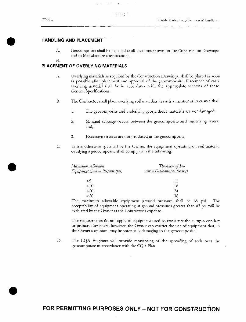
HANDLING AND PLACEMENT
A. Geocomposite shall be installed at all locations shown on the Construction Drawings and to Manufacture specifications.
B. PLACEMENT OF OVERLYING MATERIALS
A. Overlying materials as required by the Construction Drawings, shall be placed as soon as possible after placement and approval of the geocomposite. Placement of each overlying material shall be in accordance with the appropriate sections of these General Specifications.
B. The Contractor shall place overlying soil materials in such a manner as to ensure that:
1. The geocomposite and underlying geosynthetic materials arc not damaged;
2. Minimal slippage occurs between the geocomposite and underlying layers; and,
3. Excessive stresses are not produced in the geocomposite.
C. Unless otherwise specified by the Owner, the equipment operating on soil material overlying a geocomposite shall comply with the following:
Maximum Allowable Thickness of Soil Equipment Ground Pressure (psi) Above Geocomposite (inches)
<5 12 <10 18 <20 24 >20 36
The maximum allowable equipment ground pressure shall be 65 psi. The acceptability of equipment operating at ground pressures greater than 65 psi will be evaluated by the Owner at the Contractor's expense.
The requirements do not apply to equipment used to construct the sump secondary or primary clay liners; however, the Owner can restrict the use of equipment that, in the Owner's opinion, may be potentially damaging to the geocomposite.
D. The CQA Engineer will provide monitoring of the spreading of soils over the geocomposite in accordance with the CQA Plan.
FOR PERMITTING PURPOSES ONLY - NOT FOR CONSTRUCTION

FINAL Ciandv Marlcv Inc.. (.ommcrcial Landfarm
VEGETATION AND SEEDING
MATERIALS
A. Seed mixture for planting shall be as specified by the New Mexico SCS.
SITE PREPARATION
A. Remove all weeds from areas to be planted. Roughen seed bed to a depth of 2 to 4 inches by scarifying, disking, harrowing, or equivalent methods.
PLANTING
A. Plant seed using equipment and procedures appropriate for seed type at recommended by the seed supplier.
FOR PERMITTING PURPOSES ONLY - NOT FOR CONSTRUCTION

FINAL Ciandv Marlcv Inc.. (Commercial J.andhirm
DRAINAGE GRAVEL
MATERIALS
A. Drainage gravel for the work shall consist of clean, hard, durable, non-carbonate, rounded, sub-rounded to sub-angular particles that arc free of metals, roots, trees, stumps, concrete, construction debris, other organic matter, and deleterious materials and coadngs.
B. The gravel shall be screened and washed to have a gradation (when tested in accordance with ASTM D 422) after placement equivalent to the following
Sieve Percent Passing
1" 100% %" 85-100% 3/8" 12-30%. 4" 1-4% 40" 0-1%
C. Drainage gravel shall have a hydraulic conductivity of at least 1 cm/sec when hand compacted in the laboratory in 3 lifts and tested in accordance with ASTM D 2434.
D. Drainage gravel shall have less than 30% loss when tested in accordance with ASTM C 131 for abrasion and less than 12% loss when tested in accordance with ASTM C 88.
E. Drainage gravel shall have less than 5 percent loss of weight, when tested for calcium carbonate content in accordance with ASTM D 4373. This requirement may be waived by the Owner if it can be otherwise demonstrated that the material contains no significant carbonate content.
PLACEMENT AND COMPACTION
A. Gravel shall be placed at the locations and to the thicknesses shown on the Construction Drawings.
B. Gravel shall not be placed directly on the gcomembrane liner. Gravel may be placed on top of a geotextile cushion layer, geonet, geocomposite drainage layer, or gcomembrane rub sheet, as shown on the Construction Drawings. Gravel may be placed using a backhoe, front-end loader, belt conveyor, spreader box, or other method approved by the Owner, as long as the ground-pressure requirements of this Section are not exceeded. The maximum acceptable gravel drop height is 3 feet.
C. Final spreading of the gravel may be performed using a low ground-pressure dozer (Caterpillar D6H-LGP or other similar equipment approved by the CQA Engineer), low-ground pressure front-end loader, or by hand. The tracked equipment shall operate only over previously-placed gravel or other soil. The Contractor shall not operate equipment directly on geosynthetics.
FOR PERMITTING PURPOSES ONLY - NOT FOR CONSTRUCTION

FINAL Gandv Marlcv Inc., (Commercial Land farm
D. Unless otherwise specified by the Owner, the equipment used to spread gravel shall not exert ground pressures exceeding the following:
Allowable Equipment Thickness oj Gravel Ground Pressure (psi) Above Geosynthetic (inches)
<5 <10 <20 >20
12 18 24 36
The maximum allowable equipment ground pressure shall be 65 psi. The acceptability- of equipment operating at ground pressures greater than 65 psi will be evaluated bv the Owner at the Contractor's expense.
E. The Contractor shall operate equipment in a manner that is protective ot polyethylene pipes and underlying geosynthedes. I f it is suspected that damage to polyethylene pipes or underlying geosynthedes may have occurred, the Owner will instruct the Contractor to remove the overlying material to expose the potentially-damaged materials. The Contractor shall repair, at his own expense, any observed damage, in accordance with the requirements of these General Specifications.
F. Within 1 foot of the toe of a slope, gravel shall be spread by hand. Extreme care shall be taken when placing gravel to protect the installed components of the liner system.
G. Geotexule filter or cushion layers shall be placed as shown on the Construction Drawings. Geotextile filter and cushion layer placement shall be in accordance with Sccdon 02714 of these General Specifications.
[ END OF SECTION J
FOR PERMITTING PURPOSES ONLY - NOT FOR CONSTRUCTION

FINAL Ciandv Marlcv Inc., (Commercial l.andtarm
GEOMEMBRANE LINERS
RESIN
A. Reclaimed polymer shall not be added to the resin; however, the use of polymer recycled during the manufacturing process will be permitted if the recycled polymer does not exceed 2 percent by weight of the total polymer weight. The product shall be manufactured specifically for use in gcomembranes, using new, first-quality polyethylene resin.
B. Thc resin shall comply with thc following properties for high density polyethylene (HDPE):
1. Specific Gravity: 0.94 to 0.96 (ASTM D 792 Method A or ASTM D 1505)
2. Melt Index: 0.1 - 0.3 g/10 mm. (ASTM D 1238 Condition E 190/C, 2.16
kg)
3. Water absorption: 0.1% max (ASTM D 570)
GEOMEMBRANE PROPERTIES
A. Smooth or textured HDPE geomcmbranc shall be used based on the following schedule:
B. The Contractor shall require that the gcomembranes Manufacture furnish gcomembrane with minimum average roll values, as defined by the Federal Highway Administration (FHWA), meeting or exceeding the criteria specified in Fable 02775-1 and that meet the manufacturing quality control requirements of this section. The Contractor shall require the geomembrane Manufacturer to certify in writing as well as provide test results that demonstrate that the geomembrane delivered to the site complies with the properties listed in Table 0277S1.
C. In addition to the property values listed in Table 02775-1, the geomembrane material shall:
1. Contain a maximum of 1 percent by weight of additives, fillers, or extenders (not including carbon black).
2. Not have stnations, roughness (except in the case of textured HDPE geomembranes where a roughened surface is characteristic), pinholes, or bubbles on thc surface.
3. Be produced so as to be free of holes, blisters, undispensed raw materials, or any sign of contamination bv foreign matter.
4. Be manufactured in a single layer or coextruded.
INSTALLATION
FOR PERMITTING PURPOSES ONLY - NOT FOR CONSTRUCTION

FINAL Ciandv Marlcv Inc.. (Commercial Landfarm
A. Install all geomembrane in accordance with manufacture' specifications.
TABLE 02775-1 REQUIRED GEOMEMBRANE
Property Test Method 60 mil HDPE m
Thickness ASTM D1593 Para 8.1.3 (Smooth)
6 0 mil
ASTM D751 (Textured) 57 mil (min) Specific Gravity ASTM D1505 0 .940 Elongation @ Yield ASTM D638 1 3 %
Elongation @ Break ASTM D638 Speed C 5 0 0 % Smooth 1 0 0 % Textured
Tensile Strength @ Yield ASTM D638 Test Specimen Type IV
132 lb/in
Tensile Strength @ Break ASTM D638 228 lb/in Smooth 1 32 lb/in Textured
Carbon Black Content ASTM D1603 2 % to 3 %
Carbon Black Dispersion ASTM D3015 and ASTM D2663
A - 1 , A - 2 , B-1
Environmental Stress Crack ASTM D1693 1,500 hrs
Low Temperature Brittleness ASTM D746 Procedure B
-103°F
Dimensional Stability ASTM D1204 < 1 . 5 % (max)
Puncture Resistance FTMS 101C 78 lb Smooth 78 lb Textured
Note: "Va lues represent minimum average roll values (i.e., any roll in a lot should meet or exceed the values in this table). Where ranges of values are given, the average roll values must be within the specified range. The specified dimensional stability is a maximum average roll value.
TABLE 02775-2 REQUIRED GEOMEMBRANE SEAM PROPERTIES'11
ASTM D4437 I 60 Mil HDPE
Shear Fusion lbs/in
Extrusion lbs/in
120
120
Smooth
Smooth
113
113
Textured
Textured
Peel Fusion lbs/in
Extrusion lbs/in
90
80
Smooth
Smooth
90
80
Textured
Textured Note: (1) Specified properties are minimums.
[ END OF SECTION 1
FOR PERMITTING PURPOSES ONLY - NOT FOR CONSTRUCTION


Mi at-m A » ^u^mt^_^ pwaecf wnaaii HflUM.


