attachment 3 - oregon 3 . east valley water district, oregon june 2011 basis of design document ......
TRANSCRIPT

Attachment 3
East Valley Water District, Oregon
June 2011
Basis of Design Document
Fox Rd SE
Victo
r Pt R
d SE


11-1195.206 Page AC-1 Drift Creek Dam Basis of Design Document June 2011 Acknowledgements East Valley Water District
ACKNOWLEDGEMENTS Appreciation is expressed to all who contributed to the completion of this document. East Valley Water District Present Board Members: David Bielenberg, Board Chairman Duane Eder, Board Member Kristina McNitt, Secretary Glenn Goschie, Board Member Paul Kraemer, Board Member Ryan Eder, Board Member Black Rock Consulting - Program Manager Kevin Crew, P.E., Principal Water & Energy Resource Services - Project Funding Jan Lee, Owner Ellis Ecological Services, Inc. - Environmental Consulting Robert Ellis, Ph.D., Principal Scientist/President Laurel Brown, Intermediate Scientist Bolyvong Tanovan, Ph.D., P.E. - Hydrological Analyses Bolyvong Tanovan, Ph.D., P.E., Hydrologist Portland State University - Water Quality Modeling Chris Berger, Ph.D., P.E., Senior Research Associate GRI Geotechnical & Environmental Consultants - Geotechnical Assessments Dave Driscoll, P.E., GE, Principal Engineer George Freitag, CEG, Associate/Project Manager Michael Zimmerman, P.E., CEG, Senior Engineer/Geologist Murray, Smith & Associates, Inc. - Project/Civil Engineering David Leibbrandt, P.E., Principal-in-Charge Bill Hollings, P.E., Project Engineer Kate Conrad, P.E., Project Manager Tammi Connolly, P.E., Design Engineer Bill Evonuk, P.E., Project Engineer

11-1195.206 Page 1 Drift Creek Dam Basis of Design Document June 2011 Table of Contents East Valley Water District
TABLE OF CONTENTS Acknowledgements .................................................................................................. Precedes 1. INTRODUCTION Authorization and Purpose ................................................................................... 1-1 Background and Project Need .............................................................................. 1-1 Previous Project Alternatives Investigation ......................................................... 1-1 Prior Related Studies and Feasibility Investigation ............................................. 1-2 Scope .................................................................................................................... 1-3 Basic Criteria and Assumptions ........................................................................... 1-4 2. AGENCY APPROVALS & PERMITTING REQUIREMENTS General ................................................................................................................. 2-1 Water Rights ......................................................................................................... 2-1 Regulatory and Permitting Interests ..................................................................... 2-1 Conceptual Design Permitting Requirements ...................................................... 2-2 OWRD Dam Safety Requirements ....................................................................... 2-2 Fish Passage Considerations ................................................................................ 2-2 3. HYDRAULIC EVALUATION General ................................................................................................................. 3-1 Previous and Ongoing Studies ............................................................................. 3-1 Required Releases ................................................................................................ 3-2 Conceptual Spillway Design ................................................................................ 3-2 General Spillway Requirements ............................................................... 3-2 Probable Maximum Precipitation Estimation ........................................... 3-3 Probable Maximum Flood Estimation ...................................................... 3-3 Preliminary Drift Creek Dam Spillway Concept & Size Estimation ........ 3-4 Conceptual Outlet Works Design ......................................................................... 3-4 Outlet Requirements ................................................................................. 3-4 Emergency Drain Requirements ............................................................... 3-5 Preliminary Drift Creek Dam Outlet/Drain Concepts & Sizing ............... 3-5

11-1195.206 Page 2 Drift Creek Dam Basis of Design Document June 2011 Table of Contents East Valley Water District
4. GEOTECHNICAL ASSESSMENT General ................................................................................................................. 4-1 Geotechnical Investigation Results and Preliminary Recommendations ............. 4-1 Recommended Future Geotechnical Work Program ............................................ 4-2 5. DAM AND RESERVOIR CONCEPTUAL DESIGN General ................................................................................................................. 5-1 Previous Studies ................................................................................................... 5-1 Site Reconnaissance ............................................................................................. 5-1 Key Project Elements ........................................................................................... 5-2 Earthen Dam ............................................................................................. 5-2 Overflow/Emergency Spillway ................................................................. 5-2 Outlet Works ............................................................................................. 5-3 Road Relocations ...................................................................................... 5-5 Landslide Mitigation ................................................................................. 5-6 Borrow Sources ........................................................................................ 5-7 Creek Diversion During Construction ...................................................... 5-7 6. RAW WATER CONVEYANCE General ................................................................................................................. 6-1 Previous Studies ................................................................................................... 6-1 Conceptual Design Considerations ...................................................................... 6-1 7. PRELIMINARY COST ESTIMATES General ................................................................................................................. 7-1 Estimated Dam and Reservoir Project Costs ........................................................ 7-1 8. PRELIMINARY PROJECT SCHEDULE General ................................................................................................................. 8-1

11-1195.206 Page 3 Drift Creek Dam Basis of Design Document June 2011 Table of Contents East Valley Water District
9. SUMMARY General ................................................................................................................. 9-1 Summary of Findings and Recommendations ...................................................... 9-1 Recommended Next Steps .................................................................................... 9-2 APPENDIX
A. Conceptual Design Drawings B. Conceptual Level Geotechnical and Geological Investigation Report (GRI) C. Mechanical and Equipment Product Information D. Preliminary Technical Specifications List E. Common Abbreviations F. References
LIST OF FIGURES No. Title Page Figure 1 Project Overview Map .............................................................................. 1-7 LIST OF TABLES No. Title Page 3-1 Reservoir Releases .................................................................................... 3-2 7-1 Estimated Project Costs for the Drift Creek Dam and Reservoir ............. 7-3

SECTION 1
11-1195.206 Page 1-1 Drift Creek Dam Basis of Design Document June 2011 Introduction East Valley Water District
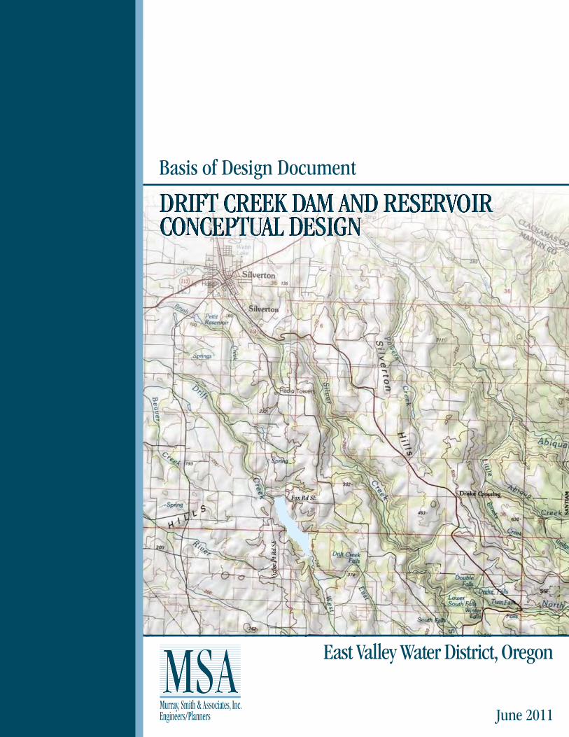
SECTION 1 INTRODUCTION Authorization and Purpose In February 2011, the East Valley Water District (District) authorized Murray, Smith & Associates, Inc. (MSA) to complete conceptual designs for the Drift Creek Dam and Reservoir located near Silverton, Oregon. The key focus of this conceptual work was to further assess the technical feasibility of the project and to develop conceptual designs in support of environmental assessments and permitting activities (by others). This conceptual work builds on prior engineering and analysis work performed by the District and was funded in part by a grant from the Oregon Water Resources Department, Water Conservation, Reuse and Storage Grant Program. This Basis of Design Document summarizes conceptual design work, presents guidance for next step engineering and geotechnical work, and provides updated project cost estimates for further financial planning and project development by the District. Background and Project Need The East Valley Water District is an irrigation district established in 2002 for the benefit of member lands and associated agricultural operations in Marion County and Clackamas County, Oregon in the general vicinity of Mt. Angel. The District’s general service area of approximately 15,000 acres extends northerly from just north of Silverton, to just south of Woodburn and Molalla, between the Pudding River on the west and the Cascade Mountain foothills on the east. The District’s approximately 75 members are currently served by individual farm wells and direct withdrawals from local surface waters. Limited surface water supplies and lowering groundwater levels make the development of a new surface water source an imperative. The District is considering the development of a new water reservoir impoundment on Drift Creek, a tributary to the Pudding River. The intended reservoir site is located approximately six miles southeast of Silverton in Marion County, and the facility would be the cornerstone of a new surface water supply system for the District. Stored winter water would be released during the summertime months and conveyed downstream to the District’s service area via either a new raw water pipeline or by natural channel flow along Drift Creek and possibly the Pudding River. Supplied water would be used for irrigation purposes and would require the development of a new water distribution piping system for delivery of irrigation water to served members. A conceptual overview and general layout of the prospective Drift Creek water supply facilities is illustrated on Figure 1. Previous Project Alternatives Investigation Various water source and storage site alternatives have been investigated by the District and others in the region. Prior studies included a Detroit-Molalla project in the 1950s, and various other sources were investigated by the Soil Conservation Services in the 1960s.
11-1195.206 Page 1-2 Drift Creek Dam Basis of Design Document June 2011 Introduction East Valley Water District
In 1993, the precursor organization to the District, the Pudding River Basin Water Resource Development Association was formed for the purpose of finding alternative sources of irrigation water. The Association, through donations and grants, raised funds to commission several studies pursuing the viability of potential sources of alternative water supplies including ground water recharge, importing water from Detroit Lake, use of municipal wastewater, and building a storage reservoir. More recently, the District has investigated project opportunities including impoundments on nearby Butte Creek (Scotts Mills Dam) and Rock Creek. Prior Related Studies and Feasibility Investigation The potential for a dam and reservoir on Drift Creek has been acknowledged for many years. Prior studies by the U.S. Department of Agriculture Soil Conservation Service (now Natural Resource Conservation Service) and others have identified a Drift Creek reservoir as one of several potential projects that might benefit the Pudding River Basin. Although the District has considered other project alternatives as discussed above, engineering and environmental assessments have established a Drift Creek dam and reservoir to be a viable and preferable option. The District’s prior Drift Creek project studies investigated the apparent technical feasibility of the proposed dam and reservoir from a general civil and geotechnical engineering perspective and from the environmental perspective. These preliminary assessments include the following: Preliminary Dam Feasibility Assessment
• Initial feasibility report by Stuntzner Engineering & Forestry, LLC (2005) • Stage-storage evaluation by Stuntzner Engineering & Forestry, LLC (2007)
Preliminary Geologic Assessment
• “Engineering Geologic Information for Feasibility of Proposed Drift Creek Dam” by H. G. Schlicker & Associates (2005)
• “Drift Creek Reservoir and Dam - Geotechnical Reconnaissance” report by Siemens & Associates (2009)
Preliminary Environmental & Permitting Feasibility Assessment
• Various environmental investigations by the Northwest Environmental and Energy Professionals (NEEP) team (2006), including: - Cultural resources investigation by Dr. Robert Keeler - Wetland delineation by Schott and Associates - Wetland mapping by Ellis Ecological Services, Inc. - Plant survey by Schott and Associates - Bird survey by Northwest Wildlife Consultants, Inc. - Fish surveys, fish passage and mitigation by Ellis Ecological Services, Inc. - Water quality by Vigil-Agrimis, Inc. - Land use
11-1195.206 Page 1-3 Drift Creek Dam Basis of Design Document June 2011 Introduction East Valley Water District
• “Determination of Appropriate Ecological and Channel Maintenance Flows for Drift Creek Downstream of the Proposed Dam” by Ellis Ecological Services, Inc. (2010)
• Drift Creek temperature and flow data by Ellis Ecological Services, Inc. (2011) Preliminary Runoff Yield Analysis
• “Runoff Yield Analysis for Drift Creek Site “A” Near Silverton, Oregon” by Dr. Bolyvong Tanovan (revised 2008)
• “Runoff Yield Analysis for Drift Creek Site “A” Near Silverton, Oregon (Update #1)” by Dr. Bolyvong Tanovan (2010)
• “Runoff Yield Analysis for Drift Creek Site “A” Near Silverton, Oregon (Update #2)” by Dr. Bolyvong Tanovan (2011)
Drift Creek Dam Site Topographic Survey
• Topographic data created by 3DI West (for Stuntzner 2007 report) Preliminary Concept Analysis
• “Overall Project Planning Assessment/Water Conveyance System Alternatives Analysis” by MSA (2007)
Such studies of the Drift Creek site have established the apparent feasibility of developing an earthen embankment type of impoundment and reservoir just upstream of the intersection of Victor Point Road and Fox Road. MSA’s 2007 planning and analysis evaluated the feasibility and comparative costs of piped raw water transmission and creek conveyance options. In 2008, with an assistance grant from the Oregon Water Resources Department, preliminary routing studies were advanced for the project’s prospective 10.5-mile water transmission piping system. While it has been recognized that the overall project faces several key challenges, no apparent “fatal flaws” have been reported to-date that would make the project non-constructible. Scope The scope of work for this conceptual design includes the following major elements: • Agency Approvals & Permitting Requirements Review – A review of permit requirements
for the conceptual design phase was performed with input from the District’s environmental consultant. Fish passage considerations were also discussed. In addition, MSA consulted with the OWRD Dam Safety group to confirm project requirements and review conceptual dam designs.
• Conceptual Level Hydraulic Evaluation – A conceptual level hydraulic evaluation of the
reservoir was performed based on hydrological information and analyses provided by the District’s hydrologist, Dr. Bolyvong Tanovan. A preliminary estimation of the Probable

11-1195.206 Page 1-4 Drift Creek Dam Basis of Design Document June 2011 Introduction East Valley Water District
Maximum Flood (PMF) was developed for the purpose of determining general sizing requirements for the emergency spillway. Additionally, a preliminary hydraulic evaluation was completed to determine the conceptual design of the reservoir outlet works for the anticipated maximum withdrawals and rapid drawdown scenarios.
• Conceptual Level Geotechnical Assessment & Geotechnical Work Plan – Conceptual level
geotechnical work included a review of prior geologic reporting, site reconnaissance and test trench excavations, laboratory testing of soil samples, and engineering analysis and design recommendations. Geotechnical assessment included investigation and evaluation of previously reported and mapped landslides within the project area and ground faults at the dam embankment location.
• Conceptual Designs, Drawings & Technical Specifications List – Conceptual design work
included a review of prior engineering studies, site reconnaissance, development of recommended design concepts, and preparation of conceptual design drawings. Conceptual designs expanded on prior project work completed by the District and incorporated conceptual hydraulic evaluation and conceptual geotechnical engineering work performed under this scope of work. Designs incorporated design review input by the District project team and OWRD Dam Safety.
• Material Quantities and Cost Estimates & Project Schedule – Conceptual level material
quantity estimates and preliminary cost estimates for the Drift Creek dam and reservoir were developed. Cost estimates include preliminary and final engineering costs, probable construction costs, administration costs, and construction contingencies. A proposed schedule for the preliminary design, final design, and construction of the prospective dam and reservoir was also developed.
• Basis of Design Document – This Basis of Design Document presents the conceptual design
work completed relative to the above project tasks. Basic Criteria and Assumptions Conceptual design work was based on previous project studies and information provided by the District. Such prior work established the following criteria.
• Prospective dam to consist of impervious earthen-fill embankment
• Location of dam to be approximately 1,100 feet upstream of existing Victor Point Road Bridge
• Target reservoir volume is 12,000 AF
• Normal maximum water surface elevation is 677 feet for 12,000 AF reservoir pool
volume based on stage-storage data

11-1195.206 Page 1-5 Drift Creek Dam Basis of Design Document June 2011 Introduction East Valley Water District
Conceptual designs were based on the above criteria and the following additional primary assumptions and considerations.
• Basic Dam/Reservoir Concepts -- Embankment fill will consist of suitable borrow material from the upstream pool inundation area. Approximately 3 feet of freeboard and about 7 feet of flood storage to be provided between maximum water surface elevation and crest of dam to accommodate the Probable Maximum Flood.
• Geotechnical Assessments -- Future geotechnical engineering work during preliminary and final project design phases will address: (a) subsurface soil and rock conditions beneath the embankment, reservoir, and spillway; (b) suitability of available borrow sources and disposal areas for reservoir construction; (c) final location of emergency spillway; (d) shear strength and permeability of the in situ foundation material; (e) shear strength and permeability of the compacted embankment soils; (f) seepage losses through the embankment and reservoir area; and (g) static and seismic stability of the embankment and surrounding slopes.
• Emergency Spillway -- A preliminary estimated Probable Maximum Flood (PMF) was established based on existing information and simplified hydrologic calculations. Flood storage was accommodated based on engineering judgment and standard industry practice for dams of this magnitude. More rigorous hydrologic/hydraulic modeling will be conducted to determine the design PMF as part of future final design work. An “Ogee-Weir” style reinforced concrete structure is assumed.
• Outlet Works & Fish Screening -- Multiple outlet ports with drum-style fish screen systems to be provided upstream for proper flow control and anticipated water temperature management requirements. Piping and mechanical components to be sized for maximum 40 cfs in-stream water rights (fish flow) releases and for maximum 40 cfs District irrigation supply demand. A downstream diversion structure to be considered for alternative conveyance options for District supply.
• Fish Passage -- Fish passage requirements are being established by others. Fish passage provisions and concept designs will be developed by others.
• Permitting Technical Support -- Environmental assessments and permitting evaluations are being performed by others. An Environmental Impact Statement (EIS) or Environmental Assessment (EA) process is anticipated. It is anticipated that conceptual drawings developed herein by MSA (related civil engineering elements) will be referenced by environmental reporting and permitting applications prepared by others.
• Base Mapping -- Electronic topographic mapping previously developed for the project was provided by the District. Mapping, developed from aerial photography, provides 2-ft contours at the dam site with 10-ft contour intervals elsewhere.

11-1195.206 Page 1-6 Drift Creek Dam Basis of Design Document June 2011 Introduction East Valley Water District
• Cost Estimates & Project Schedule -- Preliminary conceptual-level cost and schedule estimates for construction are based on general assumptions and MSA’s recent construction experience on similar projects in the local Willamette Valley area. Estimates assume the use of private construction contractors and conventional public procurement/contracting procedures. As cost estimates are not based on detailed designs, appropriate contingencies and other provisions for engineering and administration have been incorporated to enable estimates to be suitable for general planning and budgeting purposes.


SECTION 2

11-1195.206 Page 2-1 Drift Creek Dam Basis of Design Document June 2011 Agency Approvals & Permitting Requirements East Valley Water District
SECTION 2 AGENCY APPROVALS & PERMITTING REQUIREMENTS General There are a variety of regulatory and permitting interests that must be considered relative to the prospective Drift Creek dam and reservoir. New dam construction involves a complicated process of environmental, water rights, land use and dam safety related consultations, reviews, approvals and permits. Dam construction must address impacts to existing properties, streamways and wetlands, as well as impacts to stream hydrological characteristics relative to fishery interests. Dam design, construction and operation must also address a broad range of safety issues. Successful implementation of this project relies significantly on the careful planning and successful permitting of the project. Water Rights Under Oregon law all natural occurring water is publicly owned, and in most cases special regulatory permission must be obtained from the Oregon Water Resources Department (OWRD) to use water from streams, lakes or underground aquifers. Water rights permits for diversion and storage purposes must be obtained prior to construction of such facilities and the actual use of the water. New water rights are “perfected” through a three step process which includes: (1) applying for and receiving a permit from the OWRD to use water from the source; (2) construction of necessary facilities to harness the water and the commencement of water use, and (3) certification of the permitted use by a Certified Water Right Examiner (CWRE) and issuance of a water right certificate. Specific time limits and milestones must be met once a permit has been issued and before it can be certified. The water right applicant generally has a limited time to construct facilities and begin using the water as detailed in their permit. The definition of “beginning construction” varies depending on whether the source is surface water or groundwater. Generally, for a surface water right, the applicant must begin construction of a project to withdraw the water, which can be as minor as starting to install a transmission pipeline to the source, in order to satisfy the requirement. Once a water right is obtained and as long as water is available, the holder can divert water, without waste, up to the amount and for the beneficial use specified in the permit. The date an application is filed with the OWRD usually establishes the order of use, and is called the priority date of the right. Water rights permits will need to be procured for the Drift Creek project. The District has begun the process and anticipates submitting applications by the end of the year. Regulatory and Permitting Interests The District has completed a number of environmental surveys and investigations, including threatened and endangered species surveys, cultural survey, wetlands delineation assessment,

11-1195.206 Page 2-2 Drift Creek Dam Basis of Design Document June 2011 Agency Approvals & Permitting Requirements East Valley Water District
ecological/channel maintenance flows analysis, stream temperature and flow monitoring, water quality modeling, and fish passage assessment work. Based on these initial assessments, no listed fish/wildlife/plant species were observed and no significant cultural or historical resources were identified. Wetland delineation of a 240-acre reservoir footprint identified an estimated total wetland area impact of 23 acres. Conceptual Design Permitting Requirements Ellis Ecological Services, Inc. (EES), the District’s environmental consultant, is providing on-going environmental assessment and permitting services for the project. Based on discussions with the District and EES, it is anticipated that a “NEPA” Environmental Impact Statement (EIS) process will be required for the project. Although no project permit submittals are required at the conceptual design phase of the project, the primary purpose of this report is to support the environmental assessment work for the project and provide conceptual design drawings for accompanying future environmental document submittals. OWRD Dam Safety Requirements The State Dam Safety Engineer at OWRD reviews dam construction plans and monitors the development of dam projects through construction and into operation. A copy of this report has been sent to the State Dam Safety Engineer. While there are no specific submittal requirements at this phase of the project, early review by Dam Safety is beneficial. It has been requested that OWRD review comments be provided directly to the District so they could be attached to this report in the District’s file and addressed with subsequent design work. The State Dam Safety Engineer makes determinations as to a dam’s established hazard designation. High hazard dams require special Seismic Hazard Analysis, a Dam Failure and Flood Analysis and the development of associated Flood Mapping. Also required for high hazard dams is the development of an Emergency Action Plan. Dam Safety Requirements are established as part of the OWRD Dam Safety review and approval process. For conceptual design of proposed hydraulic structures, MSA consulted with Dam Safety staff to confirm Dam Safety requirements, to review approach and criteria for preliminary Probable Maximum Flood (PMF) estimation, and to discuss preliminary concepts for the proposed project. Fish Passage Considerations Fish passage must be accommodated in new dam projects unless it is determined to be technically infeasible. Current State regulations allow for consideration of a fish passage waiver where infeasibility is proven and where agreed mitigation provides a net benefit to fish.

11-1195.206 Page 2-3 Drift Creek Dam Basis of Design Document June 2011 Agency Approvals & Permitting Requirements East Valley Water District
The District, with the assistance of EES, is currently investigating passage feasibility and possible mitigation opportunities along Drift Creek and nearby streams. Based on initial discussions with Oregon Department of Fish and Wildlife (ODFW), it is understood that additional assessment work and agency reviews are necessary. Conceptual designs for the prospective dam do not include fish passage facilities. Such provisions, if determined to be required, will be addressed in later project design phases. Design development of any potential fish passage facilities should be accomplished in coordination with aquatic biologists and regulatory agencies and should consider reservoir pool elevation fluctuation, required releases for instream flows, and temperature control. The design of fish passage facilities would influence the operating characteristics of the reservoir and type and location of outlet works for the dam. A requirement for fish passage could adversely affect the feasibility of the project from a cost-benefit perspective.

SECTION 3

11-1195.206 Page 3-1 Drift Creek Dam Basis of Design Document June 2011 Hydraulic Evaluation East Valley Water District
SECTION 3 HYDRAULIC EVALUATION General A conceptual level hydraulic evaluation of the reservoir was completed using existing hydrological information and analyses previously performed for this project. The purpose of the hydraulic evaluation was to facilitate the development of concepts, evaluate alternatives, and provide for the general sizing of dam hydraulic structures. The scope of this work included the review of prior hydrological studies, concept development and sizing of the emergency spillway, and conceptual development of outlet works. Previous and Ongoing Studies Prior studies were completed to evaluate the hydrology of the basin, assess stream temperature and flows, determine the basin yield and available reservoir storage, and determine required reservoir releases for instream water rights (ecological flows), streambed flushing flows (2-year storm) and District irrigation needs. A hydrologic runoff analysis for the project site was performed in 2007 by Dr. Bolyvong Tanovan, PhD, P.E., using precipitation records, comparable watershed and stream data, and recent stream flow data collected at new stream gage stations on Drift Creek. Two subsequent updates to this report have been completed using recent additional stream flow data to further develop the runoff yield estimates and reservoir operation projections determined by hydrologic models. Although actual discharge data for Drift Creek is limited, Dr. Tanovan’s analyses concluded that the likelihood of an October-April runoff volume of 12,000 AF available for District use is reasonably good. As required by the Oregon Department of Fish and Wildlife (ODFW), a study was completed by Ellis Ecological Services, Inc. (EES) in 2010 to estimate necessary ecological and channel maintenance flows for Drift Creek downstream of the proposed dam location. Ecological flows are those flows that trigger or support fish migration, spawning, and other habitat conditions. Channel maintenance flows, or flushing flows, are those flows that move the coarse bed size streambed material found downstream of the dam. It was determined that the peak flow for a 2-year flood event, equating to approximately 630 cfs at the proposed dam site, would be adequate for this purpose, and all flows equal to or greater than this should be bypassed by the dam. It was also noted that required releases for ODFW’s instream water rights is adequate to trigger upstream fish migration and provides adequate water depths in the reach, therefore no added ecological flows would be required to be released. As part of current conceptual project work, a study was conducted by Portland State University, led by Dr. Chris Berger, PhD, P.E., to evaluate and model potential water quality impacts to Drift Creek due to the development of the proposed dam. As required by the Oregon Department of Fish and Wildlife (ODFW), flows released from the dam must mimic
11-1195.206 Page 3-2 Drift Creek Dam Basis of Design Document June 2011 Hydraulic Evaluation East Valley Water District
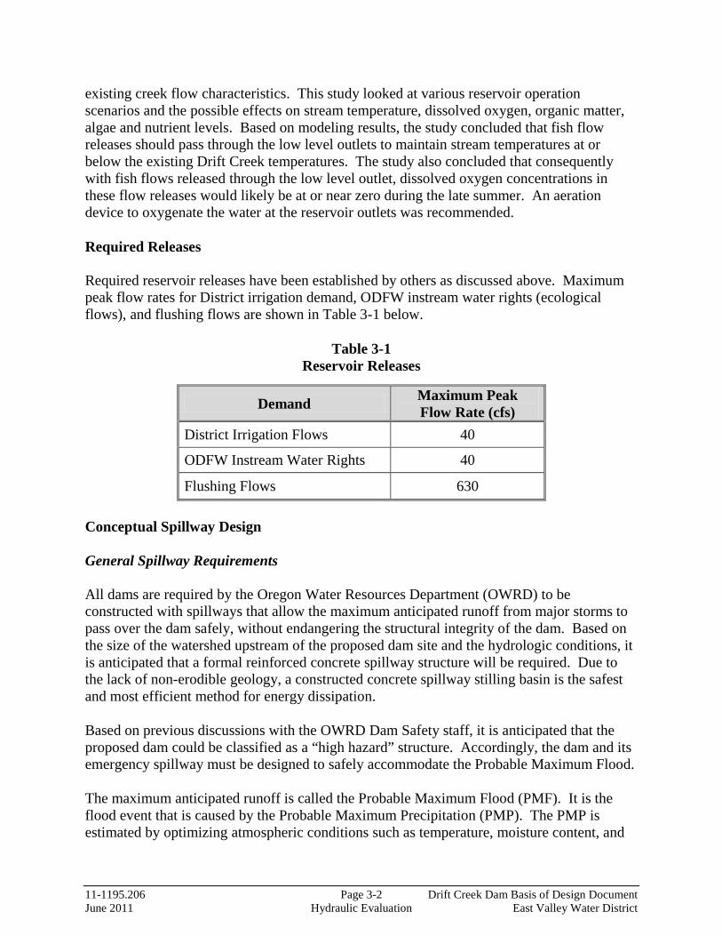
existing creek flow characteristics. This study looked at various reservoir operation scenarios and the possible effects on stream temperature, dissolved oxygen, organic matter, algae and nutrient levels. Based on modeling results, the study concluded that fish flow releases should pass through the low level outlets to maintain stream temperatures at or below the existing Drift Creek temperatures. The study also concluded that consequently with fish flows released through the low level outlet, dissolved oxygen concentrations in these flow releases would likely be at or near zero during the late summer. An aeration device to oxygenate the water at the reservoir outlets was recommended. Required Releases Required reservoir releases have been established by others as discussed above. Maximum peak flow rates for District irrigation demand, ODFW instream water rights (ecological flows), and flushing flows are shown in Table 3-1 below.
Table 3-1 Reservoir Releases
Demand Maximum Peak Flow Rate (cfs)
District Irrigation Flows 40
ODFW Instream Water Rights 40
Flushing Flows 630 Conceptual Spillway Design General Spillway Requirements All dams are required by the Oregon Water Resources Department (OWRD) to be constructed with spillways that allow the maximum anticipated runoff from major storms to pass over the dam safely, without endangering the structural integrity of the dam. Based on the size of the watershed upstream of the proposed dam site and the hydrologic conditions, it is anticipated that a formal reinforced concrete spillway structure will be required. Due to the lack of non-erodible geology, a constructed concrete spillway stilling basin is the safest and most efficient method for energy dissipation. Based on previous discussions with the OWRD Dam Safety staff, it is anticipated that the proposed dam could be classified as a “high hazard” structure. Accordingly, the dam and its emergency spillway must be designed to safely accommodate the Probable Maximum Flood. The maximum anticipated runoff is called the Probable Maximum Flood (PMF). It is the flood event that is caused by the Probable Maximum Precipitation (PMP). The PMP is estimated by optimizing atmospheric conditions such as temperature, moisture content, and

11-1195.206 Page 3-3 Drift Creek Dam Basis of Design Document June 2011 Hydraulic Evaluation East Valley Water District
winds to determine the upper limit of precipitation that the atmosphere can produce for the location being studied. The rainfall depth is distributed over a 72-hour period and a PMF hydrograph is estimated using a model which accounts for local soil runoff characteristics and base flows. Where appropriate, the water contributed by snowmelt is also included in the flood hydrograph. The PMF is then routed through a model of the reservoir. The reservoir acts as a detention basin, storing a large portion of the PMF in the reservoir, between the crest of the spillway and the top of the dam, for release after the storm ends. The remaining portion passes through the spillway. The spillway discharge capacity determines how high the water level in the reservoir rises above the top of the spillway crest. Probable Maximum Precipitation Estimation A preliminary estimate of the PMP depth was determined using the upper Drift Creek drainage basin characteristics and the National Weather Services’ Hydrometeorological Report No. 57 (HMR No. 57) procedure for determining the PMP. The procedures described in HMR No. 57 recommend that the following PMP storms be evaluated to determine the critical probable maximum storm for the watershed:
• All-season 72-hour PMP • Seasonal 72-hour PMP storm with snow pack
The 72-hour all-season and seasonal PMP depths were determined, without snow pack consideration. The 72-hour all-season scenarios resulted in a total rainfall depth of 21.6 inches. A review of seasonal PMP variation percentages throughout the Pacific Northwest region (HMR No. 57 Figures 15.2-15.8) showed that November through February is the season with the highest precipitation at the Drift Creek Dam site. For this period, no seasonal adjustment to the 72-hour all-season PMP depth is required. An incremental rainfall distribution of the PMP was developed as described in HMR No. 57. Probable Maximum Flood Estimation With the assistance of Dr. Bolyvong Tanovan, a preliminary estimated PMF design hydrograph was developed for the proposed reservoir to determine the conceptual configuration of the proposed spillway. Dr. Tanovan utilized two computer models that he developed for prior project work; one modeling the hydrology of the Drift Creek Dam watershed (rainfall-runoff model, FLO4DRIFT), and the second modeling the reservoir pool and dam hydraulic structures (RES4DRIFT). Both project computer models were updated to accommodate a 6-hour time step calculation and to incorporate a spillway structure element for the reservoir. The estimated PMP rainfall distribution was input into the watershed model to determine the runoff hydrograph for the PMP design storm. This runoff hydrograph was then input into the

11-1195.206 Page 3-4 Drift Creek Dam Basis of Design Document June 2011 Hydraulic Evaluation East Valley Water District
reservoir model (essentially routed the storm flow through the reservoir) to obtain a PMF outflow hydrograph over the spillway. Flood storage was accommodated based on engineering judgment and standard industry practice for dams of this magnitude. The results of the preliminary modeling determined an estimated peak PMF of approximately 3,800 cfs with a runoff volume of approximately 31,800 AF. Preliminary Drift Creek Dam Spillway Concept & Size Estimation Conceptual design of the proposed spillway was based on a similar approach and design criteria used for prior, similar dam projects approved by OWRD Dam Safety. Based on our experience and preliminary PMF determination, an approximate 7 feet of flood storage was incorporated to accommodate the estimated PMF. A reinforced concrete spillway structure with ogee crest is recommended to accommodate the high volume, high velocity flow storm events. Conceptual sizing of the spillway width was estimated using the reservoir computer model. A maximum water surface elevation of 684 feet (approximately 7 feet above the spillway crest) was established as a design criterion, which would provide flood storage and a required minimum 3 feet of freeboard (distance between the maximum water surface elevation and the dam crest). The spillway width (weir length), which was the design variable, was adjusted with each model run scenario to determine an approximate width with respect to spillway discharge capacity and target head condition. Based on this work, an approximate 50-foot width was determined. This conceptual level hydraulic evaluation and modeling work considered the following assumptions:
• Snow melt considered negligible; • Full reservoir condition at time of PMP design storm; • Outlet/drain piping valves closed so full PMF routes over spillway; • Preliminary estimate of 7 feet of flood storage
It is recommended that these assumptions be further evaluated and addressed in more detailed hydraulic evaluations completed with future project final design work. Conceptual Outlet Works Design Outlet Requirements Reservoir outlets are sized to allow the maximum required water demand to be withdrawn. For this project, the outlet works must be sized to economically accommodate the various required release flows as discussed above.
11-1195.206 Page 3-5 Drift Creek Dam Basis of Design Document June 2011 Hydraulic Evaluation East Valley Water District
Emergency Drain Requirements A dam’s drain structures must be capable of draining the reservoir quickly to minimize the risk of catastrophic failure of the dam and potential damage downstream of the dam, should a structural problem or large leak develop. At a minimum, the emergency drain should be capable of emptying the reservoir within 30 days, in accordance with State guidelines for dam construction. While the minimum State guidelines allow for calculating the draining time assuming no inflow into the reservoir, it is recommended that normal inflow be included. It is not economically feasible to be able to drain the reservoir within 30 days under all inflow conditions, such as major storm events. Preliminary Drift Creek Dam Outlet/Drain Concepts & Sizing Alternative outlet works configurations were considered based on various reservoir uses, anticipated release flows, frequency of releases, and cost considerations. To provide operational flexibility and redundancy, dual combination outlet/drain pipes were considered. Emergency Rapid Drawdown Requirement A preliminary hydraulic evaluation of the reservoir was performed to estimate sizing of the proposed outlet/drain piping. For this level of evaluation, no reservoir inflow was considered. Based on this evaluation, two outlet/drain pipes, approximately 48-inch and 36-inch diameters, could pass a combined flow of 630 cfs, at full reservoir stage, and could drain the reservoir pool in an estimated 15 days. During an emergency drawdown, hydraulically operated sluice gates on the outlet/drain pipes would be fully opened, utilizing the full capacity of the pipes. Should the pipes be required to pass such a high flow, at an estimated resultant velocity of 30 feet per second, it is anticipated that severe damage to the dam outlet works would occur due to cavitation and scour. Such a rapid drawdown could cause sloughing of the dam face and could trigger landslides around the pool perimeter. It is important to note that this is a worst-case scenario, where the reservoir would be required to be drained quickly due to imminent dam failure, and the future condition of the outlet works would not be an overriding consideration. District & Ecological Flow Considerations During normal operating conditions, the reservoir outlet works would be required to pass the ODFW instream water right flows and District irrigation flows, each with anticipated flow rates of up to 40 cfs. It is recommended that flows be throttled by upstream control valves and passed through smaller outlet piping connections into the larger combined outlet/drain piping. Multiple outlet ports at low level and mid level reservoir elevations would allow full range of reservoir depth and operational flexibility for water temperature management of releases.
11-1195.206 Page 3-6 Drift Creek Dam Basis of Design Document June 2011 Hydraulic Evaluation East Valley Water District
Flushing Flow Considerations As discussed above, streambed flushing flow releases have been established as the 2-year flood event, approximately 630 cfs, and flows equal to or greater than this should be passed through the dam. While there are no current regulatory requirements that dictate the accommodation of these high flows through reservoir outlet works, such a scenario was considered. From this assessment several key issues were identified, including velocity considerations within the outlet/drain piping and the economic feasibility considerations of accommodating a large “tunnel” for immediate and frequent large storm releases. To provide for lower, more acceptable (“safer”) velocities, much larger piping, control valves, outlet structures and related appurtenances, such as trash racks and fish screens would be required. Additionally, storm flows would be buffered by the reservoir and would likely require releases of stored water to augment storm outflows. These augmented flow releases will need to be defined with respect to reservoir operating conditions. It is possible that these releases would necessitate drawdown rates that exceed safe recommended rates for the dam and reservoir, putting the earthen embankment and reservoir pool slopes at risk (and landslide areas) for slope failures. It was recognized that further definition of regulatory guidelines/future requirements is needed, which would need to address magnitude of storms considered, timing/frequency of releases, operational conditions of reservoir during storm events, and storm flow monitoring and control management. At this time, it is recommended that conceptual designs for the prospective dam and reservoir consider passing flushing flow releases and larger storms over the spillway. Proposed Outlet Works Concept Based on the above considerations, it is proposed that the Drift Creek dam and reservoir have two large diameter combination outlet/drain pipes with six upstream reservoir outlet ports at multiple elevations. Four control valves and two sluice gates would control flows entering the outlet/drain pipes. Flows would outfall through sluice gates into a common stilling basin for energy dissipation immediately downstream of the dam embankment. Further discussion of these and other key hydraulic structures is presented in Section 5.

SECTION 4
11-1195.206 Page 4-1 Drift Creek Dam Basis of Design Document June 2011 Geotechnical Assessment East Valley Water District
SECTION 4 GEOTECHNICAL ASSESSMENT General A conceptual-level geotechnical assessment was completed of the proposed reservoir site by Murray, Smith & Associates, Inc.’s (MSA) geotechnical engineer, GRI Geotechnical & Environmental Consultants (GRI). A report of this assessment and findings are included in Appendix B. The purpose of the preliminary assessment was to investigate the existence of fault-induced ground rupture beneath the dam site, generally assess the risk and impacts of reactivation of mapped landslides, and develop recommendations in support of conceptual designs of the dam and reservoir. The scope of the assessment included review of prior geologic studies and subsurface information, ground-level geologic reconnaissance, test trench and pit excavations, laboratory tests, and engineering analyses and recommendations. Geotechnical Investigation Results and Preliminary Recommendations Although significant additional preliminary and final design level geotechnical investigations and engineering are required, the following conclusions and recommendations indicate that the site appears to be generally favorable from a geotechnical and geological perspective.
1. Geotechnical observations at the site and subsurface explorations did not disclose evidence of past fault-related ground rupture beneath the dam footprint. The potential for fault-related ground rupture within the dam footprint is judged to be low.
2. Based on geotechnical observations at the site, limited subsurface explorations, and review of work by others at the site, the hillsides adjacent to the pool area are reported to be mantled and underlain by landslide debris, or weathered rock and soil that had a high risk of slope instability. Landslides mapped through previous work on this project and based on observations revealed that topography indicative of past landslide activity extends west of Victor Point Road SE in some areas. Given these large areas of potential slope instability around the pool, it is not judged to be practical or cost-effective to design mitigation approaches for future possible pool-induced landslides. It is advised that such risk be part of the overall project implementation considerations.
3. Additional exploration work should be accomplished to further evaluate potential borrow areas away from the proposed embankment location. The amount of borrow material available around the dam footprint appears limited to about 2 to 4 feet below the ground surface. To prevent pool floor leakage, borrow areas should be limited in depth to leave at least a 2-foot thick layer of relatively impermeable fine-grained soil above weathered bedrock.

11-1195.206 Page 4-2 Drift Creek Dam Basis of Design Document June 2011 Geotechnical Assessment East Valley Water District
4. Based on the preliminary assessment results and our team’s experience with similar projects, it is judged that the proposed earthfill embankment section is feasible and may be constructed with an adequate factor of safety for internal slope stability. However, to safely and economically construct the embankment, a well thought out and sequenced plan of construction work, including foundation preparation, excavation dewatering, select use of available borrow materials, internal drainage and filters, and slope protection will be required.
Recommended Future Geotechnical Work Program Moving forward through the design process, additional geotechnical assessments will be required, building upon previous work. Recommended geotechnical work includes the following tasks:
• Preliminary Design – Building upon the site investigations performed during
conceptual design, deep subsurface explorations are recommended to further assess the onsite soil characteristics. Borings, drilled to depths up to 100 feet, should be used to obtain soil samples and install piezometers to log the piezometric pressure. A permanent inclinometer should be installed in the landslide near the left dam abutment at Victor Point Road to monitor ground stability.
• Seismic Hazard Studies – A review of existing information regarding the seismicity of the proposed reservoir site should be carried out in order to estimate the ground response during a design earthquake event. Attention should be paid to the potential for amplification of incoming seismic energy throughout the dam and reservoir site and the peak ground/bedrock acceleration should be determined.
• Final Design Studies – Final design work should include an evaluation of the final dam embankment footprint and areas which require landslide buttressing. Soil samples from previously identified borrow areas should be tested further in a laboratory to verify their suitability for embankment material. Water seepage through the proposed embankment should be evaluated to determine if a drainage blanket within the embankment is necessary. Slope stability analyses should be performed for static and seismic loading conditions. Additional, more detailed geotechnical recommendations should be developed to support final dam and reservoir designs.

SECTION 5
11-1195.206 Page 5-1 Drift Creek Dam Basis of Design Document June 2011 Dam and Reservoir Conceptual Design East Valley Water District
SECTION 5 DAM AND RESERVOIR CONCEPTUAL DESIGN General Conceptual design engineering was conducted to establish, evaluate and present proposed concepts for the contemplated Drift Creek dam and reservoir. Conceptual designs expanded on project work completed to date and incorporated conceptual hydraulic evaluation and conceptual geotechnical engineering work performed under this scope of work. Design work included review of prior studies and project information, site reconnaissance, evaluation of various conceptual alternatives, development of design recommendations, preparation of conceptual design drawings, and development of conceptual level cost estimates and project schedule. Estimated costs and schedule are discussed in later sections of this report. Previous Studies Previous studies determined the size and location of the proposed Drift Creek Dam, based on the geology and topography of the site and a target storage volume of 12,000 AF to meet the irrigation water supply needs of the District. In 2005, Stuntzner Engineering & Forestry, LLC (Stuntzner) assisted the District with an initial feasibility study for the prospective dam and reservoir. This initial investigation built upon previous siting investigations in 1969 by the Pacific Northwest River Basins Commission – Willamette Basin Task Force. Using USGS topographic contours, Stuntzner located the Drift Creek dam at a point where the valley narrowed, minimizing the size of the dam and founding the embankment on basalt rock. H.G. Schlicker & Associates, Inc. assisted Stuntzner with initial geologic assessments and recommendations. Based on the topography of the site, Stuntzner determined that more than the initially considered 8,000 AF volume could be impounded. In 2007, Stuntzner developed estimated reservoir pool stage-storage data for a 12,000 AF reservoir volume, based on electronic topographic data created by 3DI West from aerial photography. The estimation used 2-foot contours at the dam site location to develop the stage-storage data with 10-foot stage increments. A maximum dam height of 680 feet was used which accommodated only 3 feet between the normal high water surface elevation and the dam crest, with no consideration for storage of flood events. This preliminary crest elevation determined an approximate dam height of 65 feet. Site Reconnaissance A site visit was conducted on March 2, 2011 with representatives from MSA and GRI to familiarize the project team with field conditions in accessible key areas of the reservoir inundation area and dam site. Permission to access private property at the dam site and along the east side of the reservoir pool area was obtained by Ellis Ecological Services, Inc. The proposed
11-1195.206 Page 5-2 Drift Creek Dam Basis of Design Document June 2011 Dam and Reservoir Conceptual Design East Valley Water District
dam would inundate a valley with a fairly flat bottom surrounded by rolling forested hills. An existing farmhouse and a cattle enclosure are the only structures within the reservoir inundation area. The valley floor is agricultural land, supporting cattle and grass seed crops. Evergreen trees along the eastern side of the valley were observed to be slightly askew, indicating mild slope movement along the length of the reservoir. Topography on the west side of the reservoir, observed from across the valley, indicates similar slope movement. The dam site appears to be located on an outcrop of basalt rock at a narrowing in the valley. Potential borrow areas were identified for future geotechnical analysis in the relatively flat cattle pasture just upstream of the proposed dam site. Key Project Elements A list of key project elements follows, some of which have been addressed in previous sections of this report and are summarized below. Earthen Dam The District previously established the Drift Creek Dam to be an earthen dam, located near the intersection of Fox Road and Victor Point Road in a narrow valley. Conceptual dam design work determined that an approximately 70-foot high dam embankment is required to impound 12,000 acre-feet of water. The proposed dam crest would be about 20-feet wide, approximately 850 feet long with an elevation of about 687 feet, which is seven feet higher than the crest elevation proposed in previous studies. The revised dam crest elevation would accommodate the Probable Maximum Flood while allowing for a minimum 3 feet of freeboard between the maximum water surface elevation and the dam crest. Conceptually, the embankment dam structure would be founded on bedrock and consist of a homogeneous impervious core constructed with locally available materials, with a downstream slope of approximately 2H:1V and an upstream slope of approximately 2.5H:1V. For slope protection, the upstream and downstream faces of the embankment would be overlaid with riprap and crushed rock, respectively. Within the dam embankment, a granular drainage blanket with a perforated drain piping system is recommended to control seepage and groundwater levels. Based on the proposed basic dam geometry, the total fill volume of the dam embankment is estimated at approximately 130,000 cubic yards. Overflow/Emergency Spillway An overflow/emergency spillway is required to safely pass large storm events through the reservoir. Based on the size of the watershed upstream of the proposed Drift Creek dam site and expected hydrologic conditions, it is anticipated that a high capacity reinforced concrete spillway structure will be required. The general requirements and preliminary hydraulic evaluation for the proposed spillway are discussed in Section 3. Based on our conceptual level hydraulic evaluation of the reservoir, a concrete spillway structure with ogee crest is recommended. Conceptually, the spillway would be a cast-in-

11-1195.206 Page 5-3 Drift Creek Dam Basis of Design Document June 2011 Dam and Reservoir Conceptual Design East Valley Water District
place concrete structure, approximately 300 feet long and 50 feet wide at the crest, with a concrete stilling basin section at the base of the structure for energy dissipation of flows prior to discharging to Drift Creek. Final design of the proposed spillway will require a detailed hydraulic engineering analysis to further define the key design elements of the spillway including approach channel, ogee weir crest, conveyance chute, spillway stilling basin and return channel to Drift Creek. Because of the favorable geologic conditions at the dam site, the proposed spillway could be located at either abutment. To better accommodate access to control structures and a more ideal location for the diversion structure, the left abutment was selected. Outlet Works As discussed in Section 3, the outlet works for the proposed dam will need to accommodate multiple uses with varying release requirements. The various uses including irrigation supply, stream flow augmentation, and flood control will impact the design and operation of the outlet works and control systems. The outlet works would generally consist of screened outlet structures, piping through the dam, and hydraulically controlled valves and gates for flow control. The hydraulic operating system would be located in an operations building where electrical instrumentation and control would be housed. Operation could be accomplished either on-site and/or remotely via a telemetry based control system. Outlet/Drain Piping Based on the conceptual alternatives and preliminary sizing assessment of proposed outlet works structures as discussed in Section 3, two parallel combination outlet/drain pipes, approximately 36-inch and 48-inch diameters, are recommended. These pipes would be sized to allow the ability to rehabilitate the pipes in the future using a lining system. Piping material considerations could include heavy wall reinforced concrete pressure pipe or concrete encased steel pipe. The average estimated length of each outlet/drain pipe would be approximately 360 feet. The proposed conceptual piping and outlet works configuration is shown on the Conceptual Design Drawings included in Appendix A. Dual, low level, combination use piping with multiple outlet ports allows for redundancy and operational flexibility of the system and reservoir storage supply. It should be noted, however, that other options could be considered which may better accommodate future established uses and reservoir operational requirements as defined with later project design phases. Control Valves, Sluice Gates & Fish Screens Control valves are proposed at the upstream outlets in the reservoir. These valves would control reservoir releases through the mid and low level outlet ports. Long radius elbow body valves are recommended, which are specialized valves designed to handle high head conditions in a raw water application. The operating range requirements of this system is
11-1195.206 Page 5-4 Drift Creek Dam Basis of Design Document June 2011 Dam and Reservoir Conceptual Design East Valley Water District
anticipated to be between 1 cfs to 40 cfs, depending on the District’s water needs and the ecological flow rate required downstream. Multiple parallel valves may be required to serve this wide operating flow range, with one smaller valve for low flows, and one larger valve for high flows. The preliminary recommendation is for an 8-inch low-flow valve for flows ranging from 1 cfs to 7 cfs, and a 20-inch valve for high release rates between 7 cfs and 40 cfs. Each valve pair would be located within a cast-in-place concrete outlet structure with a trash rack to protect the outlet works from debris during reservoir draining and low level reservoir operations. In addition, large stainless steel drum screens at control valve connections are recommended to protect fish from the outlet works. These screens should be designed with a screen slot size capable of passing the required 40 cfs flow rate and with a maximum screen flow-through velocity of 0.5 fps to prevent fish from being pulled into the outlet works. Fish screen systems should incorporate an automated cleaning system such as an airburst system. Sluice gates are recommended at each end (upstream and downstream) of the reservoir drain pipes. These large sluice gates would operate fully open or closed for the purpose of draining the reservoir. Additionally, sluice gates are recommended to isolate flows entering the diversion structure. All sluice gates on the upstream side of the dam embankment are anticipated to be hydraulically operated while downstream gates would include manual operators. An air vent system is recommended for each upstream control valve and sluice gate to prevent a vacuum condition in the outlet/drain pipes. Diversion Structure Conceptual designs incorporate a diversion structure as part of the proposed outlet works configuration. This structure, located at the downstream toe of the embankment, would allow flows to be collected and routed into a raw water transmission pipeline, conveying irrigation water from the proposed Drift Creek Dam site to the District’s service area. The proposed structure would be cast-in-place concrete with associated piping connections to both reservoir outlet/drain pipes for redundancy and flexibility for reservoir operations and maintenance activities. Stilling Basin A stilling basin at the reservoir outlet works and spillway outfalls is required for energy dissipation and for creek bottom/ bank protection. A riprap lined basin is recommended, and conceptually would be constructed within and around the creek channel at these outfall locations. A general outline of the basin has been included on the Conceptual Design Drawings. The stilling basin configuration will create a pool of standing water which will dissipate energy in the discharge flows prior to flows re-entering Drift Creek. The basin will be heavily armored with large diameter riprap boulders to prevent scour in the basin.
11-1195.206 Page 5-5 Drift Creek Dam Basis of Design Document June 2011 Dam and Reservoir Conceptual Design East Valley Water District
Aeration Considerations As discussed in Section 3, a study was conducted by Portland State University to evaluate and model potential water quality impacts to Drift Creek due to the development of the proposed dam. Based on the modeling work, it was recommended that all fish flow releases should pass through the low level outlets, and an aeration device should be utilized to oxygenate the water discharging to the creek. Various alternatives could be considered for aeration provisions including mechanical devices or outfall stilling basin modifications. One option to consider might be the use of a fixed cone valve (Howell-Bunger Valve) or a ring jet valve. Water with low dissolved oxygen content can be aerated very effectively when discharged into the atmosphere through Howell-Bunger Valves. It is recommended that further analysis be conducted during future design work to evaluate alternatives and determine best option for the project. Road Relocations The Drift Creek dam and reservoir project must include provisions for construction access and modifications to existing roadways impacted by embankment construction. Certain private properties and potentially the County right-of-way will be affected. Victor Point Road Realignment Conceptual designs indicate the need to relocate Victor Point Road. As discussed above, the conceptual dam crest elevation has been revised from that considered in previous studies in order to accommodate the Probable Maximum Flood. The proposed “raise” allows room for storm surges while maintaining the target storage volume of 12,000 AF with a normal high water surface elevation of 677 feet. The revised crest elevation of approximately 687 feet is higher than Victor Point Road, and dam embankment fills appear to impact the existing roadway. It appears that approximately 800 lineal feet of Victor Point Road would need to be relocated approximately 100 feet to the west. Road relocation considerations would likely include slope stabilization measures along the roadway slope nearest the dam and would impact private property and require adjustment of the public right-of-way. Conceptual designs reflect a conservative scenario from a permitting perspective. Although it is preferred to avoid relocating Victor Point Road, moving the existing roadway away from the dam and reservoir site is beneficial. This would likely reduce the potential risk of roadway structural failure due to possible reactivation of landslides and would likely reduce the extent of slope stabilization measures required for the road. As discussed in Section 3, the conceptual design of the spillway applied a similar design approach used for similar recent dam projects as was judged appropriate by OWRD Dam Safety. However, to reduce or possibly avoid impacts to Victor Point Road, it may be feasible to lower the dam crest, widen the spillway and reduce flood storage considerations, within practical limitations. This may provide for a cost savings for the dam embankment

11-1195.206 Page 5-6 Drift Creek Dam Basis of Design Document June 2011 Dam and Reservoir Conceptual Design East Valley Water District
and roadway relocation but will likely come at an increased cost to spillway construction. An optimization analysis is recommended as part of subsequent project design work to assess alternatives and compare costs. Additionally, as an alternative, the District could consider reducing the storage volume goal and respective dam height, recognizing however, the need to maintain storage volume for ODFW instream water rights releases. Access Roads Access roads are required to allow District maintenance personnel and trucks access to dam abutments, the spillway, and the outlet works. Options for constructing access roads off of both Victor Point Road and Fox Road were considered, with access off of Fox Road being the recommended alternative. An existing dirt road extends approximately 800 feet from Fox Road southeasterly to the proposed dam site. This road may be utilized for access to the northwest side of the dam, as shown on Sheet EMB-1, the Embankment Site Plan. A 10-foot wide, approximately 500 foot long access road would extend across the downstream embankment slope (at approximate elevation 640 feet) to the spillway, eliminating the need to construct a bridge over Drift Creek. A second proposed gravel access road approximately 150 feet long would lead off of Fox Road to allow access to the operations building on the north end of the dam crest. Landslide Mitigation As part of conceptual geotechnical assessment work, prior reporting of mapped landslides was reviewed and hillside conditions at the site were generally investigated for evidence of slope instability. A discussion of related site observations, findings and recommendations is presented in a technical memorandum prepared by GRI included in Appendix B. Based on geotechnical findings, large portions of the reservoir pool perimeter are reported to or appear to exhibit poor slope stability. The general limits of reported landslides and areas of potential slope instability are shown on the Conceptual Design Drawings. Although it is not practical or cost effective to mitigate these large areas for future possible pool-induced landslides, there are two key areas of concern which should be further evaluated for landslide/slope stability mitigation. A large previously mapped ancient landslide on the west side of the project site appears to extend from the proposed reservoir pool area to the west past Victor Point Road. Reactivation of this landslide will likely result from filling and operating the reservoir. Based on the conceptual configuration of the dam, the left abutment would extend within this impact area. Consequently, roadway relocation designs for Victor Point Road will need to consider slope stabilization measures such as an anchored wall along the slope nearest the dam. Another area of concern is the hillside below a potential archeological site identified in prior cultural investigation work and reporting for the project. This potential site is generally described as located above the eastern middle portion of the project area. The District has
11-1195.206 Page 5-7 Drift Creek Dam Basis of Design Document June 2011 Dam and Reservoir Conceptual Design East Valley Water District
completed a Cultural Resources study for the project area and has submitted an evaluation to the Oregon State Historic Preservation Office for review. It is understood that a landslide in this vicinity could impact the potential site within the slide limits. As such, it is recommended that the hillside below this potential site be further investigated to evaluate the risk of slope failure and potential impact to upslope area and to determine specific mitigation measures required, if warranted. Borrow Sources One of the primary economic advantages of an earthen dam is that the construction materials already exist on-site. Based on the conceptual geotechnical work completed under this scope, it appears that suitable construction materials exist at the proposed site to support construction of an earthen dam. Test pits excavated in the valley floor near the embankment identified layers of clayey silt and decomposed sedimentary rock which appear suitable for use as impermeable embankment fill material. However, additional exploration work will be required to verify that suitable quantities of borrow material exist at the site. Granular material for slope protection and embankment filter drain will need to come from off site. The nearby quarry on Victor Point Road may be a suitable source for these materials and should be further investigated with subsequent project design work. Creek Diversion During Construction It is anticipated that Drift Creek flows will need to be preserved during dam and reservoir construction activities. Flows would need to be bypassed around work zones and coordinated with staged dam embankment work. According to the Oregon Department of Fish and Wildlife (ODFW) guidelines, the in-water work period for the Pudding River Watershed is from June 1 to September 15. The extent and duration of creek diversion activities will be stipulated by project permitting.

SECTION 6

11-1195.206 Page 6-1 Drift Creek Dam Basis of Design Document June 2011 Raw Water Conveyance East Valley Water District
SECTION 6 RAW WATER CONVEYANCE General There are two key means by which stored water in the proposed Drift Creek Reservoir can be conveyed to the District’s water service area for distribution. An extensive raw water pipeline could be constructed between the dam site and the District service area, potentially serving much of the District by gravity. Alternatively, Drift Creek and possibly the Pudding River could be used as a natural conveyance channel, with summertime reservoir releases being withdrawn downstream by means of new intake and pumping facilities. Previous Studies In 2007, MSA worked with the District to complete an Overall Project Planning Assessment report to establish an overall project direction, with a focus on evaluating raw water conveyance alternatives and related costs. Comparative cost estimates for water conveyance alternatives indicated that a creek/river conveyance and downstream pumping station concept is of significantly lesser cost, both on an initial project cost basis and a present worth cost basis, than a gravity piped water transmission system, considering the present worth value of long term operations and maintenance costs, power costs and future replacement costs for major equipment. At the time, the District considered a Pudding River Pumping Station system alternative to be least desirable from a water quality perspective. It was recommended that the matter be further reviewed by the District in light of apparent costs. The following year, in 2008, MSA completed the Preliminary Transmission Pipeline Routing Analysis technical memorandum. The purpose of this grant funded study was to further develop the transmission pipeline alternatives, focusing on assessing and defining potential pipeline routing alternatives. Several alternative pipeline alignments were assessed between the proposed Drift Creek Dam and the District’s irrigation water distribution system. While the District desires to develop a piped water transmission system that would deliver irrigation water to the District by gravity, the initial construction cost of the required 10-mile pipeline is recognized as a significant challenge. It should also be noted that considerable planning work remains to be done toward the establishment of an irrigation distribution system. Preliminary discussions with District Board representatives indicate a wide range of alternatives that might be considered involving the use of new Drift Creek Project facilities and capacity in combination with existing individual groundwater and surface water rights. Conceptual Design Considerations At this time, the District is still considering a final decision on a water transmission methodology to deliver raw water from the proposed Drift Creek Reservoir to the District’s

11-1195.206 Page 6-2 Drift Creek Dam Basis of Design Document June 2011 Raw Water Conveyance East Valley Water District
distribution system. Therefore, the conceptual design of the Drift Creek Dam outlet works allows for flexibility and may accommodate either discharging District irrigation releases into Drift Creek or routing flow through a diversion structure and into a raw water transmission pipeline at the base of the dam. The proposed diversion structure, located on the north bank of Drift Creek at the toe of the dam embankment as shown on the Conceptual Design Drawings in Appendix A, would be connected to both reservoir outlet/drain pipes allowing the option to route flow from either or both outlet/drain pipes and multiple reservoir outlets. In-line valves on piping entering the structure would be used to isolate and bypass flows to the creek.

SECTION 7
11-1195.206 Page 7-1 Drift Creek Dam Basis of Design Document June 2011 Preliminary Cost Estimates East Valley Water District
SECTION 7 PRELIMINARY COST ESTIMATES General The development of the Drift Creek Project represents a major capital undertaking. Each of the three major project elements; the Drift Creek Dam, the stored water conveyance system and the irrigation distribution system, are multi-million dollar propositions. In advance of any construction, is the significant cost of project engineering, environmental assessments, property acquisition and permitting. Following construction are the significant costs of on-going system management, operation and maintenance. Conceptual level project cost estimates for the planned dam and reservoir are presented herein. These estimated costs are budgetary estimates based preliminary concepts. The cost estimates are opinions of cost only, as final costs of the projects will vary depending upon labor and material costs, market conditions for construction, regulatory requirements, final project scope, project schedule and other factors. Estimated Dam and Reservoir Project Costs Estimated project costs for the dam and reservoir are based on engineering judgments as to current probable construction costs. These preliminary construction costs estimates are based on general assumptions and MSA’s recent construction experience on similar projects in the local Willamette Valley area. Estimates assume the use of private construction contractors and conventional public procurement/contracting procedures. As estimates are not based on detailed designs, appropriate contingencies and other provisions for engineering and administration are incorporated to enable estimates to be suitable for general planning and budgeting purposes. Project costs consist of estimated construction costs in 2011 dollars, plus an aggregate 45 percent allowance for engineering, permitting, administration and contingencies. The “45 percent” allowance that is then added to basic construction costs to develop estimates of “project costs”, as referenced herein, may be generally broken down as follows: Construction Contingencies ................................................................................................. 25% Engineering (Design and Construction Management) ........................................................ 15% Permitting............................................................................................................................ 2.5% Administration/Legal/Misc ................................................................................................. 2.5% TOTAL @ 45 % Since construction costs change periodically, an indexing method to adjust present estimates in the future is useful. The Engineering News Record (ENR) Construction Cost Index (CCI) is a commonly used index for this purpose. For future reference, the June 2011 ENR CCI of 8757.87 for the Seattle area construction market (the nearest market ENR monitors) may be used in the future to update cost estimates in this report.

11-1195.206 Page 7-2 Drift Creek Dam Basis of Design Document June 2011 Preliminary Cost Estimates East Valley Water District
The estimated construction costs have been separated into the following major categories:
• Mobilization – consists of moving in, bonds, insurance, cleanup and moving out.
• Site Preparation – consists of tree removal, clearing and grubbing, stripping and stockpiling topsoil, haul roads, and general erosion control and dewatering facilities
• Dam Excavation/Embankment Construction – consists of excavating an average 10 feet below dam embankment to rock foundation; excavating and placing impervious fill for dam embankment and abutments from borrow material obtained from reservoir pool area; preparation, hauling and placing rock surfacing/armoring from nearby quarry.
• Spillway – consists of excavation, construction of concrete spillway weir, chute and stilling basin.
• Hydraulic Structures, Valves and Piping – consists of outlet/drain piping, outlet control valves, sluice gates, outlet structures, fish screens and air burst cleaning system, diversion structure, and excavated rock lined outfall/stilling basin.
• Operations Building, Hydraulic Operating System, and Electrical Instrumentation & Control – consists of small pre-engineered package-style building with electronic signaling and recording equipment, hydraulic power unit, SCADA equipment and stand-by power generator.
• Access Roads/Roadway Relocations – consists of relocating County roads and provisions for new access off Fox Road to hydraulic and diversion structures at base of dam and access to control building at the dam crest.
• Landslide Mitigation – consists of anchored wall along relocated portion of Victor Point Road (approximately 1,000 lf) and compacted soil-amended buttress (assuming 50ft x 500ft area, total 25,000 cy) at base of hillside below potential archeological site.
The locations of the proposed dam and reservoir improvements are shown on the Conceptual Design Drawings included in Appendix A. A summary of the estimated project costs is presented in Table 7-1. These costs are based on the construction timeline as shown in the preliminary construction schedule included in Section 8.
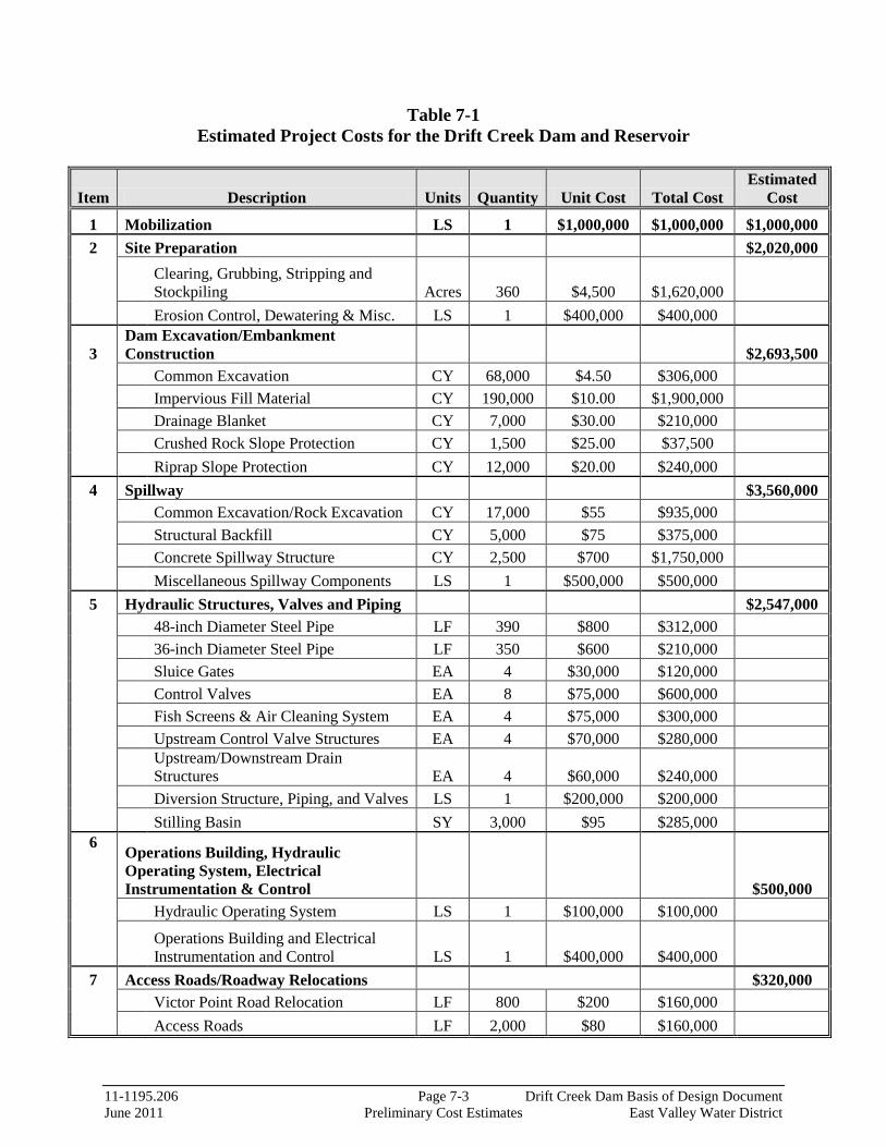
11-1195.206 Page 7-3 Drift Creek Dam Basis of Design Document June 2011 Preliminary Cost Estimates East Valley Water District
Table 7-1 Estimated Project Costs for the Drift Creek Dam and Reservoir
Item Description Units Quantity Unit Cost Total Cost Estimated
Cost
1 Mobilization LS 1 $1,000,000 $1,000,000 $1,000,000 2 Site Preparation $2,020,000
Clearing, Grubbing, Stripping and Stockpiling Acres 360 $4,500 $1,620,000
Erosion Control, Dewatering & Misc. LS 1 $400,000 $400,000
3 Dam Excavation/Embankment Construction
$2,693,500
Common Excavation CY 68,000 $4.50 $306,000 Impervious Fill Material CY 190,000 $10.00 $1,900,000 Drainage Blanket CY 7,000 $30.00 $210,000 Crushed Rock Slope Protection CY 1,500 $25.00 $37,500 Riprap Slope Protection CY 12,000 $20.00 $240,000 4 Spillway $3,560,000 Common Excavation/Rock Excavation CY 17,000 $55 $935,000 Structural Backfill CY 5,000 $75 $375,000 Concrete Spillway Structure CY 2,500 $700 $1,750,000 Miscellaneous Spillway Components LS 1 $500,000 $500,000 5 Hydraulic Structures, Valves and Piping $2,547,000 48-inch Diameter Steel Pipe LF 390 $800 $312,000 36-inch Diameter Steel Pipe LF 350 $600 $210,000 Sluice Gates EA 4 $30,000 $120,000 Control Valves EA 8 $75,000 $600,000 Fish Screens & Air Cleaning System EA 4 $75,000 $300,000 Upstream Control Valve Structures EA 4 $70,000 $280,000
Upstream/Downstream Drain Structures EA 4 $60,000 $240,000
Diversion Structure, Piping, and Valves LS 1 $200,000 $200,000 Stilling Basin SY 3,000 $95 $285,000 6 Operations Building, Hydraulic
Operating System, Electrical Instrumentation & Control $500,000
Hydraulic Operating System LS 1 $100,000 $100,000
Operations Building and Electrical Instrumentation and Control LS 1 $400,000 $400,000
7 Access Roads/Roadway Relocations
$320,000 Victor Point Road Relocation LF 800 $200 $160,000 Access Roads LF 2,000 $80 $160,000

11-1195.206 Page 7-4 Drift Creek Dam Basis of Design Document June 2011 Preliminary Cost Estimates East Valley Water District
8 Landslide Mitigation $1,250,000 Victor Point Road Anchored Wall LS 1 $750,000 $750,000
Eastern Buttress (Potential Cultural Site) CY 25,000 $20 $500,000
Estimated Construction Costs Subtotal $13,890,500
Engineering, Administration, and Construction Contingency @ 45% of Total Construction Cost $6,250,000
Total Estimated Project Cost (Dam/Reservoir only, 2011 $'s) $20,140,500 Rounded $20,000,000
Footnote: Budgetary estimate does not include cost estimates for property acquisition, environmental mitigation, permitting or fish passage mitigation.

SECTION 8

11-1195.206 Page 8-1 Drift Creek Dam Basis of Design Document June 2011 Preliminary Project Schedule East Valley Water District
SECTION 8 PRELIMINARY PROJECT SCHEDULE General Attached is a proposed project schedule showing the time periods for the key tasks required to complete preliminary and final engineering and construction for the Drift Creek dam and reservoir. The schedule assumes concurrent execution of multiple work tasks to achieve desired project milestones. It is recognized, however, that project financing along with permitting and regulatory approvals are critical path items and will dictate the overall project schedule. A two to three year construction period is anticipated. Due to the moisture sensitive fine-grained soils on site, the placement and compaction of borrow material in the dam embankment will be limited to periods of extended dry weather, which typically occur from about mid-June to mid-September. As such, two or more summer construction seasons may be required to complete earthwork construction.
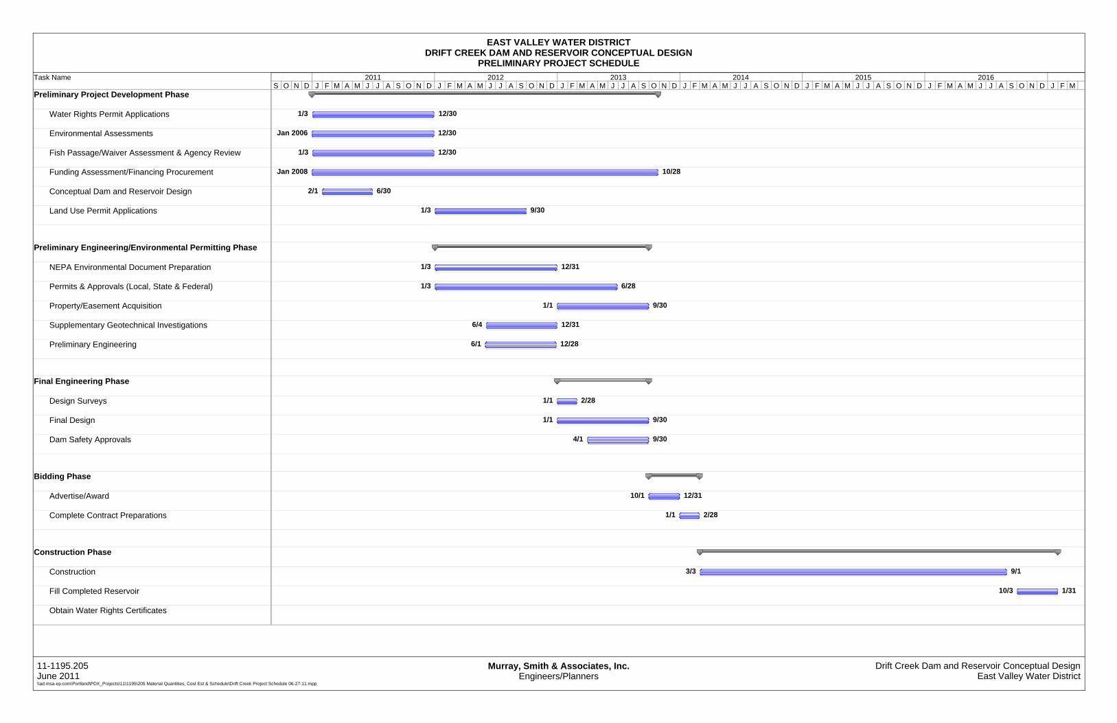
Task Name
Preliminary Project Development Phase
Water Rights Permit Applications
Environmental Assessments
Fish Passage/Waiver Assessment & Agency Review
Funding Assessment/Financing Procurement
Conceptual Dam and Reservoir Design
Land Use Permit Applications
Preliminary Engineering/Environmental Permitting Phase
NEPA Environmental Document Preparation
Permits & Approvals (Local, State & Federal)
Property/Easement Acquisition
Supplementary Geotechnical Investigations
Preliminary Engineering
Final Engineering Phase
Design Surveys
Final Design
Dam Safety Approvals
Bidding Phase
Advertise/Award
Complete Contract Preparations
Construction Phase
Construction
Fill Completed Reservoir
Obtain Water Rights Certificates
1/3 12/30
Jan 2006 12/30
1/3 12/30
Jan 2008 10/28
2/1 6/30
1/3 9/30
1/3 12/31
1/3 6/28
1/1 9/30
6/4 12/31
6/1 12/28
1/1 2/28
1/1 9/30
4/1 9/30
10/1 12/31
1/1 2/28
3/3 9/1
10/3 1/31
S O N D J F M A M J J A S O N D J F M A M J J A S O N D J F M A M J J A S O N D J F M A M J J A S O N D J F M A M J J A S O N D J F M A M J J A S O N D J F M2011 2012 2013 2014 2015 2016
EAST VALLEY WATER DISTRICTDRIFT CREEK DAM AND RESERVOIR CONCEPTUAL DESIGN
PRELIMINARY PROJECT SCHEDULE
11-1195.205June 2011\\ad.msa-ep.com\Portland\PDX_Projects\11\1195\205 Material Quantities, Cost Est & Schedule\Drift Creek Project Schedule 06-27-11.mpp
Murray, Smith & Associates, Inc.Engineers/Planners
Drift Creek Dam and Reservoir Conceptual DesignEast Valley Water District

SECTION 9

11-1195.206 Page 9-1 Drift Creek Dam Basis of Design Document June 2011 Summary East Valley Water District
SECTION 9 SUMMARY General This section presents a summary of the findings and recommendations presented in previous sections for the prospective Drift Creek dam and reservoir, including recommended next steps for further project implementation. Summary of Findings and Recommendations The conceptual design work completed under the scope of this project has developed preliminary concepts for a prospective dam and reservoir project on Drift Creek as outlined below.
• Dam Embankment - Conceptual design engineering has established the basic shape and footprint of the dam as well as a conceptual internal “picture” of the embankment. An approximately 70-foot high, 850-foot long dam embankment would be required to impound 12,000 AF of water. It is anticipated that sufficient suitable material to construct the conceptualized dam exists at the site.
• Geotechnical Assessment - The proposed dam and reservoir appears feasible from a geologic and geotechnical engineering perspective. Subsurface excavations beneath the dam footprint did not reveal evidence of past fault-related ground rupture.
• Preliminary PMF Determination - A preliminary estimation of the Probable Maximum Flood (PMF) was completed for conceptual sizing of an overflow/emergency spillway. Future design work should include more detailed hydrologic/hydraulic modeling to further refine preliminary estimates.
• Emergency Spillway - A high capacity reinforced concrete spillway structure is recommended. Conceptual hydraulic evaluation and modeling work estimate an approximate 50-foot wide spillway would be required to safely convey the full PMF. A concrete spillway stilling basin is recommended for adequate energy dissipation. A detailed hydraulic design of the spillway and stilling basin will be required as part of final design work.
• Outlet Works Configuration - Alternative outlet works configurations were considered. Dual outlet/drain pipes with multiple outlet ports, upstream control valves and downstream diversion structure are recommended to accommodate the multiple uses and contemplated reservoir operation/release scenarios. Large drum-style fish screen systems are recommended for mid and low level outlets.
11-1195.206 Page 9-2 Drift Creek Dam Basis of Design Document June 2011 Summary East Valley Water District
• Drain Requirements - A preliminary hydraulic evaluation of the reservoir was performed to size the proposed outlet/drain piping to allow rapid drawdown of the reservoir in an emergency situation. Based on this evaluation, two large outlet/drain pipes, 36-inch and 48-inch diameters, are recommended and would accommodate draining the reservoir within a 30 day period in accordance with State guidelines.
• Preliminary Costs - Initial early budgetary cost estimates were further developed to reflect conceptual level designs. The eventual realization of the project relies heavily on the ability of the District to secure financing for the overall project.
• Schedule Considerations - A preliminary project schedule for the dam and reservoir was developed identifying timelines for preliminary design, final design and construction work. The proposed schedule incorporates the District’s anticipated timeframes and milestones for permitting, water rights and other administrative tasks as well as a target construction advertise date of Fall 2013.
Recommended Next Steps To proceed with dam and reservoir final design, additional preliminary work is needed, including additional environmental and permitting assessments, further geotechnical investigations, supplementary surveying, right-of-way assessment and acquisition, water rights procurement, regulatory reviews, environmental mitigation assessment and planning, and additional project funding assessment and procurement. The following next step tasks are recommended.
• Fish Passage - complete assessments and negotiations with regulatory agencies to obtain fish passage/ waiver conclusion
• Geotechnical Investigations - complete supplemental site investigations, preliminary engineering and analyses, and seismic hazard studies as identified in the recommended future geotechnical work program included in Section 4.
• Raw Water Transmission - determine final decision for raw water conveyance method
• Distribution System - complete assessment and planning for water distribution system to District customers
• Preliminary Engineering - proceed with preliminary design engineering work, coordinating with environmental studies and permitting process
• Water Rights - prepare and file water rights applications for processing through the Oregon Water Resources Department
• Property Easement/Acquisition - program to secure required property and easements • Preliminary Regulatory Approvals and Permits - complete required preliminary
assessments, prepare various preliminary permit applications, and negotiate various approvals with respective agencies
• Project Financing - continue funding assessments and financing assistance planning/ acquisition to support further project development

APPENDIX

APPENDIX AConceptual Design Drawings
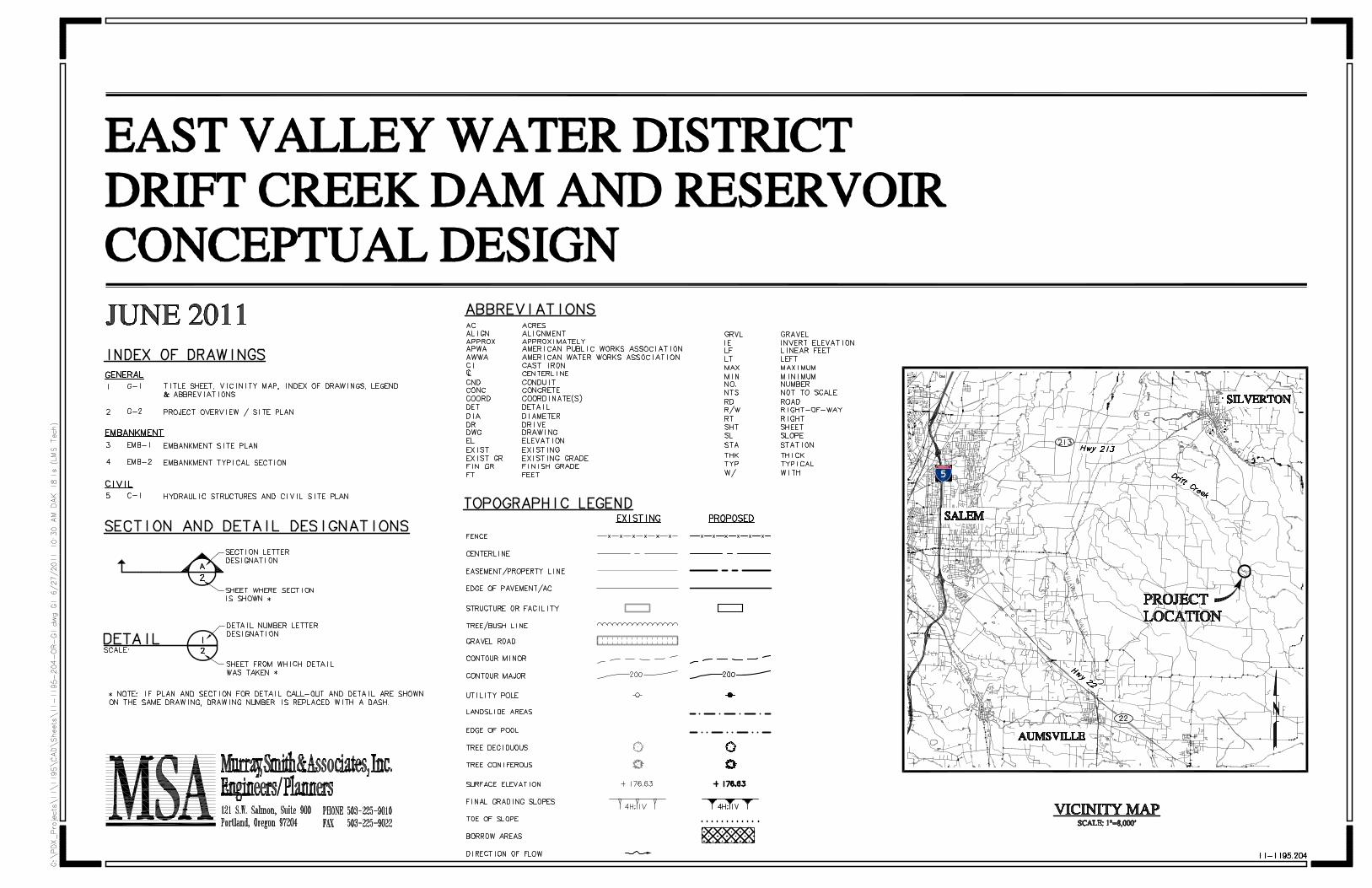


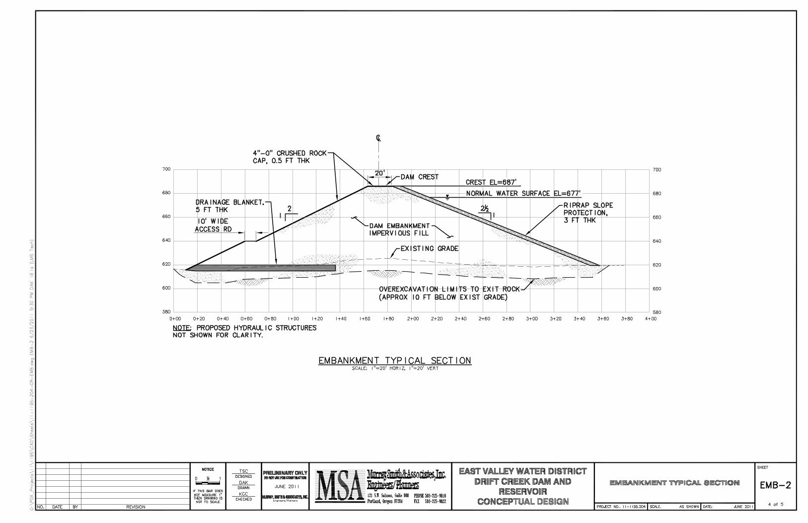


APPENDIX BAPPENDIX BConceptual Level Geotechnical and
Geological Investigation Report (GRI)
June 17, 2011 5186 GEOTECHNICAL RPT CONCEPTUAL DESIGN
Murray, Smith & Associates, Inc. 121 SW Salmon Street, Suite 900 Portland, OR 97204 Attention: Kate Conrad, PE
SUBJECT: Geotechnical Consultation Phase 1 Conceptual Design - Fatal Flaw Evaluation Drift Creek Dam Marion County, Oregon
At your request, GRI has provided geotechnical consultation for Phase 1 Conceptual Design of the proposed Drift Creek dam. The project site is located about 6 miles south of Silverton, Oregon, in a rural portion of the Waldo Hills. The general location of the site is shown on the Vicinity Map, Figure 1. The East Valley Water District will be the owner/operator of this facility, and the reservoir will be used to store water for irrigation.
The purpose of this consultation was to further evaluate two previously identified potential “fatal flaws” associated with design and construction of the proposed dam: 1) at least two fault lineaments have been mapped in the area of the dam site (Tolan and Beeson, 1999), and it is necessary to demonstrate that these faults are inactive with respect to ground rupture beneath the dam; and 2) landslides have been mapped on the west side of the reservoir; reactivation of these landslides will likely result from filling and operating the reservoir. Concurrent with our field work, we also provided the design team with general geotechnical input as requested.
Our work included a review of available information, a ground-level reconnaissance, focused subsurface explorations, laboratory testing, and engineering analyses. This report describes the work accomplished and our field explorations and laboratory testing program, and provides our findings and conclusions regarding the fault lineaments, landslide potential on the margins of the reservoir, and general considerations for design and construction of the reservoir. Our work was completed in general accordance with our proposal dated December 15, 2010.
Phase 2 will be a preliminary design and will be an expansion of the existing conceptual design studies. Phase 3 will be a detailed seismic hazard analysis, which will evaluate the response of the embankment under seismic loading. Phase 4 will be final design studies and reporting and will include assisting Murray, Smith & Associates, Inc. (MSA) in the preparation of construction drawings and specifications and the contract documents suitable for permitting and bidding the project.
BACKGROUND Previous geotechnical work and geologic mapping have been completed for the project and in the project area by others. Our consultation included review of the following reports by others:

2
“Engineering Geologic Information for Feasibility of Proposed Drift Creek Dam, Silverton area, Oregon,” prepared by H. G. Schlicker & Associates, Inc. for Stuntzner Engineering, June 24, 2005 (Schlicker)
“Geotechnical Reconnaissance, Drift Creek Reservoir and Dam, Victor Point, Oregon,” prepared by Siemens & Associates for Black Rock Consulting, July 24, 2009 (Siemens)
The Schlicker report documents the site geology and subsurface conditions around the dam site and pool. Their work indicates the dam site is underlain by basalt rock and interbedded alluvial sediments of the Drift Creek drainage (silt, sand, cobbles, and wood debris). Explorations completed in the pool area indicate the presence of silt, sand, and clay, underlain by weathered sedimentary rock. Schlicker also mapped several large areas along the western pool perimeter as being old landslides and notes that stability of the reservoir valley slopes would likely decrease as the pool was filled. Some of these large landslide areas are on the order of 2,500 by 2,000 ft in plan, or roughly 100 acres in size.
The Siemens report documents additional reconnaissance work that suggests portions of the eastern pool perimeter are steep and prone to slope instability. Geophysical work near the dam site indicates the likely presence of alluvial sediments, weathered sedimentary rock, and basalt rock.
SITE DESCRIPTION Topography The proposed reservoir site is located in the Waldo Hills upland area of the Willamette Valley. Drift Creek drains toward the northwest from higher elevation areas to the southeast. At the dam site, the topography narrows and the width of the Drift Creek valley constricts from about 1,000 to 100 ft. Available topographic information indicates the valley floor at the dam site is at about elevation 620 ft, and valley/pool perimeter ranges from about elevation 800 to 1,000 ft. Where observable and not covered by trees or dense vegetation, slopes along the majority of the pool area are irregular (hummocky).
Geology The dam site is underlain by Tertiary volcanic and sedimentary rocks. The volcanic rocks are part of the Columbia River Basalt Group, and the sedimentary rocks are locally referred to as Scotts Mills Formation. U.S. Geological Survey (USGS) geological mapping for the site is provided on the Geologic Map, Figure 2. Essentially the entire pool area is underlain by relatively weak, weathered sedimentary rock.
The Oregon Department of Geology and Mineral Industries State Landslide Inventory does not show mapped landslides within or adjacent to the pool area. However, the state landslide inventory is not comprehensive, and local areas around the site, in particular steeply sloping areas underlain by sedimentary rocks, have been mapped as landslides. As noted above, Schlicker and Siemens have mapped or interpreted large portions of the pool perimeter as ancient landslides or areas prone to slope instability.
Fault Potential USGS mapping indicates the presence of two bedrock fault lineaments north of the site in the Drift Creek drainage (Tolan and Beeson, 1999). The fault traces trend toward the location of the proposed dam, but the USGS mapping ends before (west of) the project site. These faults are not considered to have Holocene displacement (U.S. Geological Survey, 2011).
3
Groundwater This site exhibits characteristics of shallow groundwater levels, including seeps, springs, and wet depressions with attendant water-loving plants. We expect that surficial groundwater levels approach the ground surface during the wet, winter season and during periods of prolonged or intense rainfall. Regional aquifers in this area are typically located deep in the basalt underlying the area.
PROJECT DESCRIPTION The 12,000 acre-ft design developed by MSA includes an embankment up to about 65 ft high from toe to crest (crest elevation 687 ft) and about 700 ft long, constructed across the Drift Creek drainage. The proposed embankment volume will be on the order of 127,000 cubic yards. A Preliminary Grading Plan and Typical Dam Section of the proposed improvements are provided on Figures 3 and 4. The overflow spillway will be constructed on the left abutment to direct water into the drainage northwest of the reservoir. We anticipate that sufficient material to construct the conceptualized embankment can be obtained from the reservoir pool area away from the proposed dam. Granular materials suitable for use in internal drains and as riprap slope protection will need to come from off site. Victor Point Road SE is located adjacent to the west limit of the dam and will require relocation westward away from the pool. Based on topographic information, cuts on the order of 20 ft in height may be required to achieve design grades for the relocated Victor Point Road SE.
SURFACE RECONNAISSANCE The surficial conditions of the project site and slopes uphill and downhill of the site were evaluated during site visits in March and June 2011, by an engineering geologist and geotechnical engineer from GRI. During these visits, evidence of past landslide activity in the pool area was observed, including a large headscarp west of the site, west of Victor Point Road SE, and irregular (hummocky) topography throughout the slopes along the western and eastern sides of the pool. Exposures of weathered sedimentary rock were observed in the mid-eastern portion of the pool area. Relatively hard basalt rock is exposed along the nose of the ridge at the left (west) abutment.
FIELD EXPLORATIONS General On June 7, 2011, subsurface materials were evaluated with two test pits, designated TP-GRI-1 and TP-GRI-2, using a small trackhoe excavator with rubber tracks supplied and operated by Dan J. Fischer Excavating, Inc. of Forest Grove, Oregon. The approximate locations of the test pits are shown on Figure 3. All field explorations were observed by a geotechnical engineer and engineering geologist from GRI, who collected samples and maintained detailed logs of the materials and conditions encountered during the course of the work. Samples recovered from the test pits were returned to our laboratory for further examination and physical testing.
Fault Potential Evaluation To evaluate the potential presence of geologic features that may indicate the potential for fault rupture below the dam, a relatively long trench was excavated perpendicular to the narrow topographic area near the dam footprint. The location of this exploration, designated trench TP-GRI-1, is shown on Figure 3. This trench measured a total of 230 ft and was completed in accordance with a pre-approved team work plan. The trench was excavated to a depth of 3 to 4 ft and encountered a surficial 2-ft-thick layer of dark brown, clayey silt that contains many fine roots and has a blocky texture. The dark brown unit is underlain by a 1- to 2-ft-thick layer of light brown, clayey silt. The light brown, clayey silt transitioned into decomposed sedimentary rock near the bottom of the excavation along the total length of the trench. The

4
decomposed sedimentary rock has weathered to the consistency of stiff soil. Near the midpoint of the trench, a short section was excavated to a depth of about 9 ft and the decomposed sedimentary rock continued to the bottom of the excavation. Light groundwater seepage was encountered at a depth of 2.5 to 4 ft below the ground surface.
No indications of fault rupture, shearing, displaced soil horizons, or other indications of faulting were observed.
Supplemental Borrow Area Test Pit To evaluate the thickness of potential borrow materials, a test pit was excavated in the pool area on June 7, 2011. The location of this exploration, designated test pit TP-GRI-2, is shown on Figure 3. The test pit was excavated to a depth of 5 ft and encountered a surficial 2-ft-thick layer of dark brown, clayey silt underlain by a 2-ft-thick layer of light brown, clayey silt. At a depth of 4 ft, the light brown, clayey silt transitioned into decomposed sedimentary rock. Heavy groundwater seepage was encountered at a depth of 4 to 5 ft below the ground surface.
LABORATORY AND FIELD TESTING General Samples obtained from the test pits were returned to our laboratory where the physical characteristics of the samples were further documented. The laboratory testing program included natural moisture content and Atterberg limits. Torvane shear strength testing was completed in the field. The following paragraphs describe the testing program in more detail.
Natural Moisture Content The natural moisture content of the materials encountered in the test pits was determined in conformance with ASTM D 2216. The results are summarized below:
Test Pit
Sample
Depth, ft
Moisture Content, %
Soil Type
GRI-TP-1 S-1 1 39 Clayey SILT S-2 3 38 Clayey SILT
GRI-TP-2 S-1 1 38 Clayey SILT S-2 3 52 Clayey SILT S-3 5 52 Decomposed sedimentary rock
Atterberg Limits Atterberg limits tests were performed on representative samples in conformance with ASTM D 4318. The test results are shown on Figure 5.
Torvane Shear Strength The approximate undrained shear strength of relatively undisturbed soil samples was determined using a Torvane shear device. The Torvane is a hand-held apparatus with vanes that are inserted into the soil. The torque required to fail the soil in shear around the vanes is measured using a calibrated spring.
Multiple Torvane results indicate the clayey soils from test pit GRI-TP-1 have an approximate undrained shear strength of 0.50 tsf. This value is typical for relatively fine-grained soils with moderate to low strength.

5
FINDINGS AND CONCLUSIONS Based on our review of the project plans, previous work by others, and our implemented scope of work, we have developed the following findings and conclusions:
1) Our observations at the site and our subsurface explorations did not disclose evidence of past fault-related ground rupture beneath the footprint of the dam. In our opinion, the potential for fault-related ground rupture within the footprint of the dam is low.
2) Our observations at the site, subsurface explorations, and review of work by others at the site indicate the hillsides adjacent to the pool area are mantled and underlain by landslide debris or weathered rock and soil that have a high risk of slope instability. Landslides mapped through previous work on this project and our observations revealed that topography indicative of past landslide activity extends west of Victor Point Road SE in some areas. In our opinion, given these large areas of potential slope instability around the pool, it is not practical or cost-effective to design mitigation approaches for future possible pool-induced landslides. The owner must accept this risk as part of the overall project implementation.
3) Additional exploration work should be accomplished to further evaluate potential borrow areas away from the embankment (outside the area shown on Figure 3). The amount of borrow material available around the footprint of the dam appears limited to about 2 to 4 ft below the ground surface. To prevent pool floor leakage, borrow areas should be limited in depth to leave at least a 2-ft-thick layer of relatively impermeable fine-grained soil above weathered bedrock.
4) Based on the results of our work and experience with similar projects, it is our opinion the proposed earthfill embankment section is feasible and may be constructed with an adequate factor of safety for internal slope stability. However, to safely and economically construct the embankment, a well thought-out and sequenced plan of construction work, including foundation preparation, excavation dewatering, select use of available borrow materials, internal drainage and filters, and slope protection, will be required.
CONSTRUCTION RECOMMENDATIONS Seasonal Construction - Earthwork and Excavation The fine-grained soils and weathered sedimentary rock at the site are suitable for construction of the proposed homogeneous embankment; however, they are also moisture-sensitive and will be difficult to place and compact when the moisture content of the materials is significantly above optimum. It appears that the in-place moisture content of the soils is above the optimum moisture content for compaction, and the soils will require considerable drying or amendment with lime or cement to improve the workability of the material for placement as compacted structural fill. In our opinion, with or without the use of soil additives, placement and compaction of fine-grained soil at this site will be limited to periods of extended dry weather, which typically occur from about mid-June to mid-September. As a result, this project may require two or more summer construction seasons for completion of the dam earthworks.
6
Site Preparation We recommend the foundation and abutments for the proposed embankment should be cleared of timber, grubbed, and stripped of vegetation. Foundation conditions should be evaluated by the geotechnical engineer at the time of site preparation. Based on observation of the soil exposed in the test pits, the upper 2 ft of soil contains many fine roots and has a blocky texture. For the portion of the embankment footprint established on the relatively flat area near the elevation of the bottom of the pool, we recommend removing the soil from the embankment footprint to expose the underlying decomposed sedimentary rock. Exposed subgrade beneath the embankment should be scarified to a depth of about 12 in. and compacted to a minimum of 95% of the maximum dry density at a moisture content within the range of 2% below to 4% above the optimum moisture content as determined by ASTM D 698.
Areas of seepage encountered within the limits of the embankment should be evaluated by the geotechnical engineer for recommended remedial action.
Cuts and Fills Permanent cut and fill slopes should have a design slope of 2H:1V or flatter. Deep cuts for the embankment footprint will encounter shallow groundwater and weathered sedimentary rock. Based on the presence of basalt in the dam area, it is likely that trackhoe excavators will be needed to make the excavations. Excavation of weathered sedimentary rock will likely require the use of a medium-size (Cat D-7) or larger bulldozer equipped with a ripper.
On-site fine-grained soils and weathered sedimentary rock are suitable for use in structural fill. Basalt boulders should not be used in fill within the reservoir embankment. All structural fill placed on the site should be approved for placement by a qualified geotechnical engineer. The soil placed in the embankment should be free of organic material. Structural fill should be placed in 6- to 9-in.-thick lifts (before compaction) for fine-grained soil (silt and decomposed siltstone) and 9- to 12-in.-thick lifts (before compaction) for granular materials.
Fine-grained soils and weathered siltstone fill should be compacted using a large (Cat 815) or larger static segmented-pad compactor. Pieces of weathered sedimentary rock that are gravel-size or larger should break down with several passes of the segmented-pad compactor. Use of single-drum vibratory compactors fitted with segmented pads should not be allowed for compaction of fine-grained soils. Fine-grained fill should be compacted to at least 95% of the maximum dry density at a moisture content within the range of 2% below to 4% above the optimum moisture content as determined by ASTM D 698. Actual compaction procedures should be determined in the field at the time of construction by building a test section of the embankment fill material. Fills of fine-grained materials with an outer slope steeper than about 3H:1V should be overbuilt by a thickness of about 2 ft and then cut back to the final grade. It must be recognized that the moisture content of the on-site fine-grained soils and the weathered sedimentary rock is well above optimum, and the materials will require significant drying or amendment with lime or cement prior to placement and compaction.
Granular fill constructed of sand- to gravel-size material should be compacted using a large, smooth-drum vibratory roller to at least 95% of the maximum dry density as determined by ASTM D 698. Coarse granular fill from 3 to 12 in. in diameter may also be compacted into place with a large, smooth-drum roller or by track-walking with a large bulldozer until well keyed.
Side slopes of temporary cuts deeper than 4 ft should not be constructed steeper than 1H:1V. Cut and fill slopes composed of fine-grained materials will be extremely susceptible to erosion. All slopes should be
7
revegetated or otherwise protected as soon as practical following construction. Surface water should be directed away from the slopes.
Haul Roads Our experience indicates the fine-grained soils that mantle the site are sensitive to moisture content. Typically, when these soils are in excess of 4 to 5% of their optimum moisture content, construction traffic will remold, rut, and soften the soil and limit its use as a construction haul road. For this reason, we recommend that all construction traffic be limited to movement on granular work pads and haul roads during the season when the moisture content of surface soils is significantly above optimum.
In our opinion, a 12-in.-thick granular work pad should be sufficient to prevent disturbance of the subgrade by lighter construction equipment and limited traffic by dump trucks. Haul roads and other high-density traffic areas will require at least 18 to 24 in. of crushed rock to prevent subgrade deterioration. Any subgrade soils that are disturbed by construction activity should be overexcavated to firm soil and backfilled with coarse, granular compacted structural fill. Any granular fill placed for haul roads within the footprint of the embankment should be removed before constructing embankment fill. Haul road requirements will be reduced if work is accomplished during the driest months of the year.
Geotextiles may be used between the granular haul road materials and the underlying fine-grained subgrade soils as a separation filter to prevent the movement of fines into the crushed rock. Use of these fabrics may improve haul road performance and reduce maintenance, particularly during wet-weather conditions.
Construction Dewatering Construction dewatering will be essential for project completion. Based on our experience, we are of the opinion that the majority of the excavation can be completed by ditching and pumping from sumps located within the excavation. However, use of this approach will require that the excavation proceed slowly enough for the hydrostatic pressures behind the excavation face to dissipate and the groundwater surface to lower as construction proceeds. The anticipated quantity of water is difficult to estimate, since the majority of the flow, in our opinion, will come from discrete zones, cracks, and fissures in the soil and rock masses, with a very small percentage actually seeping through the soil and rock mass. Consequently, we are of the opinion that the groundwater surface behind the excavation face should fall relatively quickly following completion of the excavation at any given elevation. However, given the nature of the local geology, we also anticipate that large localized flows of groundwater may also be encountered. These concentrated flows could result in areas of instability of the cut face. It may be possible to manage these large flows by placing a layer of free-draining granular material on the exposed face of the excavation. However, if this approach is not able to maintain the stability of the face of the excavation, it will likely be necessary to install a system of relief wells above the top of excavation, or install a series of horizontal drains in the cut face. Regardless of the approach to dewatering, it will be essential to keep the bottom of the excavation free of standing water and monitor the excavation for any increases in water entering the excavation. As previously noted, areas of seepage encountered within the limits of the embankment should be evaluated by the geotechnical engineer for recommended remedial action.
Embankment Drains Permanent control of seepage through the embankment and management of groundwater levels below the embankment will be important to the stability of the structure. An internal drainage system should be constructed to lower water pressures within the downstream shell of the structure. The proposed drainage

8
consists of a drainage blanket composed of clean, open-graded granular material that daylights at the elevation of the toe of the embankment and extends to about the centerline of the embankment.
To reduce the risk of piping of the fine-grained embankment material into the drain material leading to clogging of the drain, a filter material will need to be installed between the drain and the surrounding soil. Gradation and thickness of the filter material should be determined after a drain material has been selected. A series of perforated drain pipes should be installed on about 20-ft centers in the drainage material at the downhill toe of the drainage blanket. Water in these pipes should be collected and hard-piped to a discharge point located away from the toe of the reservoir embankment.
Embankment Slope Protection Sloped portions of the embankment sides exposed to water should be lined with riprap to reduce erosion at the waterline and turbidity. The slope protection should extend from an elevation at least 2 ft below the normal low-water operating level of the reservoir to a point 2 ft above the normal high pool. The riprap should be bedded on a layer of pervious, well-graded gravel or crushed rock with material diameters ranging from about 3/16 to 31/2 in. Gradations of the blanket material can be more accurately determined once a slope protection material is selected. This bedding layer should be placed in a single lift that achieves a thickness of at least 12 in. after compaction, measured perpendicular to the slope.
Riprap placed on the embankment should have a minimum thickness of 24 in. measured perpendicular to the slope and should meet the following criteria: maximum size should equal 100 pounds, of which 30 to 40% of the material should be 60 to 100 lbs; 60 to 70% of the material should be 25 to 60 lbs; and less than 10% of the material should be under 25 lbs. The riprap should be placed in a manner to produce a uniform thickness of well-keyed, dense, uniformly distributed rock fragments.
The downstream surface of the embankment may be protected from erosion using a 6-in.-thick cap of 4-in.-minus crushed rock. Outside the area of the spillway, the surface may also be protected by planting a suitable cover of grass or other shallow rooted, low-lying ground-cover vegetation. The downstream slope should be protected from the crest of the dam to the lower limits of the embankment slope.
The surfaces of the embankment should be kept free of deeply rooted vegetation such as trees. The embankment should also be kept free of animal burrows. Downstream surfaces of the embankment and areas within 50 ft downstream of the embankment should be kept free of brushy vegetation that inhibits observations of seeps and springs that may develop following reservoir filling.
LIMITATIONS This report has been prepared to aid the owner and engineer in the conceptual planning, design, and construction of this project. The scope is limited to the specific project and location described herein, and our description of the project represents our understanding of the significant aspects of the project relevant to the earthwork and design and construction of the dam. In the event that any changes in the design and location of the dam as outlined in this report are planned, we should be given the opportunity to review the changes and to modify or reaffirm the conclusions and recommendations of this report in writing. Additional exploration and geotechnical work will be required as part of the Final Design.
The findings, conclusions, and recommendations submitted in this report are based on the data obtained from the test pits made at the locations indicated on Figure 3 and from other sources of information discussed in this report. In the performance of these types of projects, specific information is obtained at specific locations at specific times. However, it is acknowledged that variations in soil and rock conditions

9
may exist between test pit locations. This report does not reflect any variations that may occur between these explorations. The nature and extent of variation may not become evident until construction. If, during construction, subsurface conditions different from those encountered in the explorations are observed or encountered, we should be advised at once so that we can observe and review these conditions and reconsider our recommendations where necessary.
Please contact the undersigned if you have any questions or comments regarding this report, or if we can be of further assistance to you.
Submitted for GRI, George A. Freitag, CEG Michael J. Zimmerman, PE, CEG David D. Driscoll, PE, GE Associate Senior Engineer/Geologist Principal Engineer References
O’Connor, J. E., Sarna-Wojcicki, A., Wozniak, K, C., Polette, D. J., and Fleck, R. J., 2001, Origin, Extent, and Thickness of Quaternary Geologic Units in the Willamette Valley, Oregon: U.S. Geological Survey, Professional Paper 1620.
Tolan, T. L., and Beeson, M. H., 1999, Geologic Map of the Scotts Mills, Silverton, and Stayton Northeast 7.5 Minute Quadrangles, Oregon. Scale 1:24,000: U.S. Geological Survey, Open-file Report 99-141.
U.S. Geological Survey, 2006, Quaternary Fault and Fold Database for the United States, Accessed June 10, 2011, from USGS Web
Site: http//earthquakes.usgs.gov/regional/qfaults/
This document has been submitted electronically.
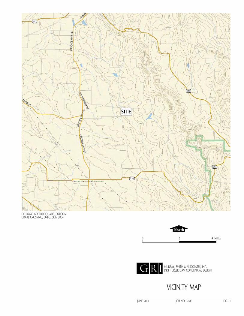
G R I
VICINITY MAP
JUNE 2011 JOB NO. 5186 FIG. 1
0 2 4 MILES
North
MURRAY, SMITH & ASSOCIATES, INC.DRIFT CREEK DAM CONCEPTUAL DESIGN
DELORME 3-D TOPOQUADS, OREGONDRAKE CROSSING, OREG. (3bb) 2004

G R I
LEGEND
GEOLOGIC MAP
JUNE 2011 JOB NO. 5186 FIG. 2
0 2.5 5 MILES
North
MURRAY, SMITH & ASSOCIATES, INC.DRIFT CREEK DAM CONCEPTUAL DESIGN
POOL
PROPOSED DAM
FROM: O'CONNOR AND OTHERS, DATED 2001

PRELIMINARY GRADING PLAN
0 160 FT
North
TEST PIT MADE BY GRI(JUNE 7, 2011)
PRELIMINARY GRADING PLAN FROM FILE BY MURRAY, SMITH & ASSOCIATES, INC.,DATED APRIL 2011
80
G R I
JUNE 2011 JOB NO. 5186 FIG. 3
MURRAY, SMITH & ASSOCIATES, INC.DRIFT CREEK DAM CONCEPTUAL DESIGN
GRI-TP-2
GRI-TP
-1

TYPICAL DAM SECTION FROM FILE BY MURRAY, SMITH & ASSOCIATES, INC., DATED APRIL 2011
G R I
JUNE 2011 JOB NO. 5186 FIG. 4
MURRAY, SMITH & ASSOCIATES, INC.DRIFT CREEK DAM CONCEPTUAL DESIGN
TYPICAL DAM SECTION
OVEREXCAVATION LIMITS TO EXISTING ROCK(APPROX 10 FT BELOW EXISTING GRADE)
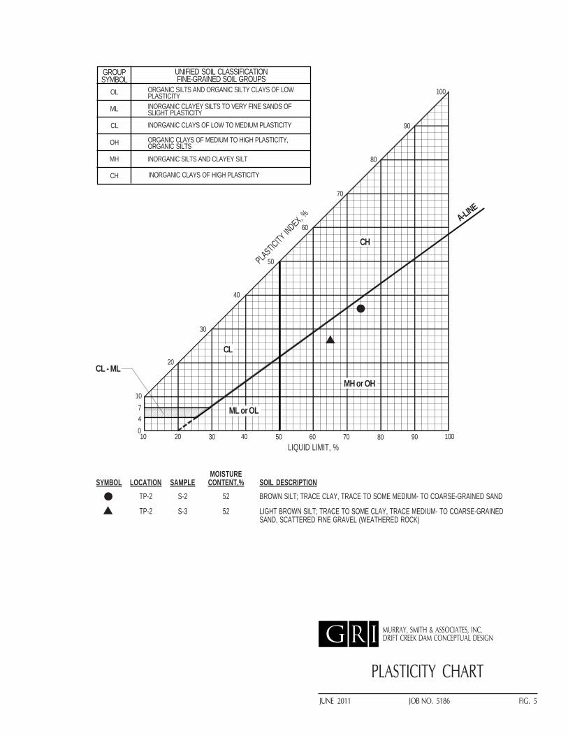
JUNE 2011 JOB NO. 5186 FIG. 5
10 20 40 50 60 70 80 90 100047
GROUPSYMBOL
UNIFIED SOIL CLASSIFICATIONFINE-GRAINED SOIL GROUPS
OL
ML
CL
OH
MH
CH
INORGANIC CLAYEY SILTS TO VERY FINE SANDS OFSLIGHT PLASTICITY
ORGANIC CLAYS OF MEDIUM TO HIGH PLASTICITY,ORGANIC SILTS
INORGANIC SILTS AND CLAYEY SILT
INORGANIC CLAYS OF HIGH PLASTICITY
MH or OH
ML or OL
CL
CH
CL - ML
10
20
30
40
50
60
70
80
90
100
A-LINE
ORGANIC SILTS AND ORGANIC SILTY CLAYS OF LOWPLASTICITY
INORGANIC CLAYS OF LOW TO MEDIUM PLASTICITY
30
PLASTICITY CHART
PLASTICITY INDEX, %
LIQUID LIMIT, %
G R I MURRAY, SMITH & ASSOCIATES, INC.DRIFT CREEK DAM CONCEPTUAL DESIGN
MOISTURESYMBOL LOCATION SAMPLE CONTENT,% SOIL DESCRIPTION
TP-2 S-2 52 BROWN SILT; TRACE CLAY, TRACE TO SOME MEDIUM- TO COARSE-GRAINED SAND
TP-2 S-3 52 LIGHT BROWN SILT; TRACE TO SOME CLAY, TRACE MEDIUM- TO COARSE-GRAINEDSAND, SCATTERED FINE GRAVEL (WEATHERED ROCK)

APPENDIX CAPPENDIX CMechanical and Equipment
Product Information
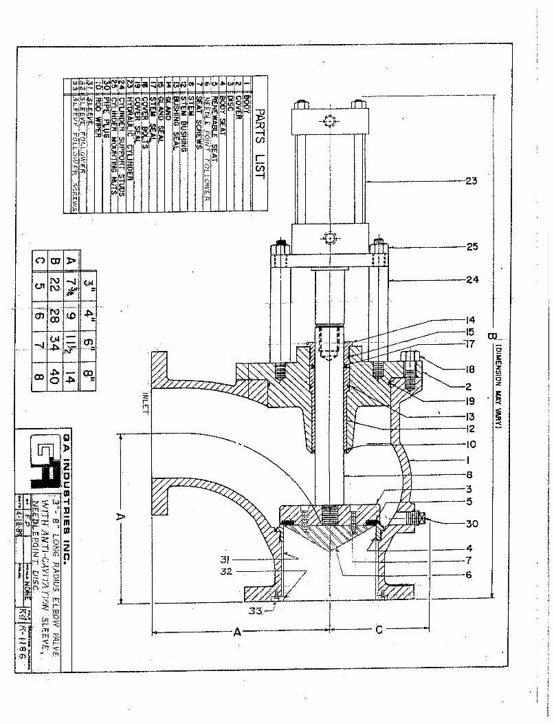
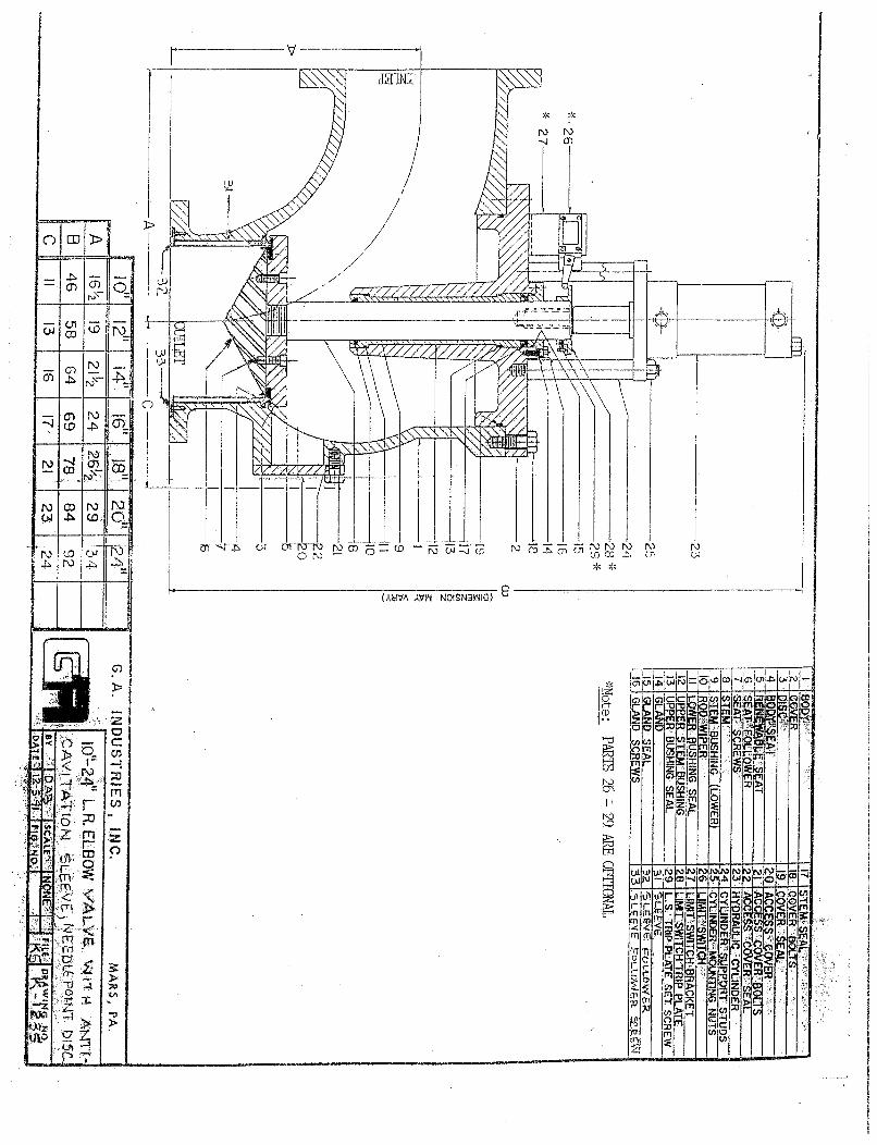
169 inches 54 Inch Includes Dished End Heads diameter 0.125 inch slot (63.78% open with #69 wire) Centerline to flange – 54 inches 4 inch Diameter AWWA Class D Flange (Hydroburst Connection) (Optional) Note – can be located at JOHNSON MODEL: T-54HCE 0. 90, 180 0r 270 degrees ( 1 ) Screen Required 36 Inch Diameter AWWA Class D Flange (Outlet Connection) Intake Screen Dimensions Estimated Total Headloss = 0.552 psi Design Flow = 40 CFS (18,000 gpm)
Approximate Weight = 7,480 lbs. Design Slot Velocity = 0.5 Max. Haskins Reservoir Material = 304 stainless steel Design Slot Velocity = 0.49 Actual Max.
A Weatherford Company

Rodney HuntSluice Gate DimensionsA ZURN Company
Presented in this brochure are the actual dimensions for sluice
gates that are suitable for the design head listed.
The sluice gates listed are not the only sluice gates available
from Rodney Hunt, but are the most common sizes and design
heads. For information on sluice gates not listed, please contact
the Rodney Hunt representative in your
area, or call us directly at 978-544-2511.
The design head is the maximum head the gate has been designed to withstand. The operating head is the head under which the gate is to be opened and closed.The operating head is used to determine the size of hoist and stem that is requiredto operate the gate and should be listed in the project specifications in addition toThe design heads.
Because of the number of gates involved, the heads for which these gates are suitable, and the several configurations in which the gate can be furnished, the best way to describe the sluice gate is by size of gate and the head for which it is designed, such as 60" x 72", 130-45. Special series gates should be described by size and series number, such as 8 x 8 Series B-240.
The dimensions listed are the actual dimensions, to the nearest 1/4", of the size of gate listed, and the head for which that gate is designed. Rodney Hunt will furnish the gate shown in the table for all applications where the head is equal to or less than the design head indicated. In some instances, several gates are listed for the same size, but with different design heads. This has been done to enable Rodney Hunt to provide the most economically designed gate for the specific design head application.
All sluice gates listed in the tables can be installed where the installation clearance along each side and along the bottom of the gate is 1". The flanges of the gate can be drilled so that the attaching studs extend to the front of the gate where they are easily accessible. Where flange frame gates are required, such as where the gate must be mounted on a circular pipe flange, the recommended installation clearance is 8" on each side and beneath the bottom of the gate.
Design Head Vs. Operating Head
How to specify
General Notes
Installation Clearance
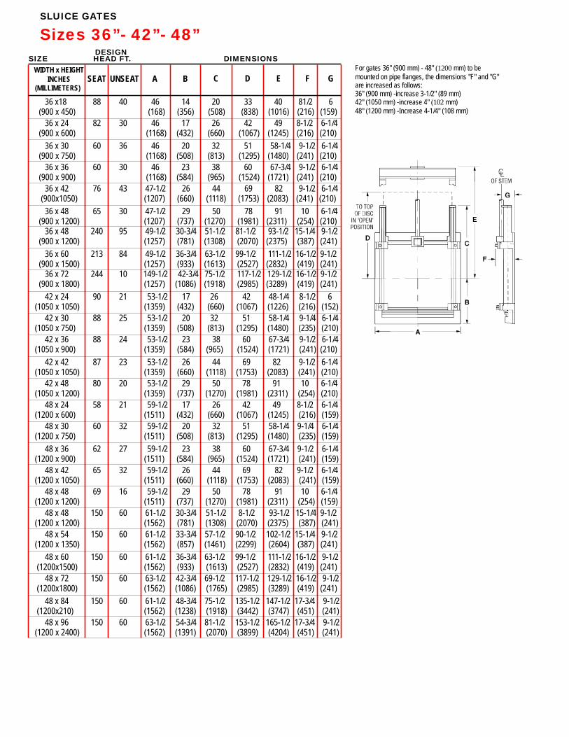
DESIGNSIZE HEAD FT. DIMENSIONS
WIDTH x HEIGHTINCHES SEAT UNSEAT A B
(MILLIMETERS)C D E F G
SLUICE GATES
Sizes 36”- 42”- 48”
For gates 36" (900 mm) - 48" (1200 mm) to bemounted on pipe flanges, the dimensions "F" and "G"are increased as follows:36" (900 mm) -increase 3-1/2" (89 mm)42" (1050 mm) -increase 4" (102 mm)48" (1200 mm) -Increase 4-1/4" (108 mm)
36 x18 88 40 46 14 20 33 40 81/2 6 (900 x 450) (168) (356) (508) (838) (1016) (216) (159)
36 x 24 82 30 46 17 26 42 49 8-1/2 6-1/4 (900 x 600) (1168) (432) (660) (1067) (1245) (216) (210)
36 x 30 60 36 46 20 32 51 58-1/4 9-1/2 6-1/4 (900 x 750) (1168) (508) (813) (1295) (1480) (241) (210)
36 x 36 60 30 46 23 38 60 67-3/4 9-1/2 6-1/4 (900 x 900) (1168) (584) (965) (1524) (1721) (241) (210)
36 x 42 76 43 47-1/2 26 44 69 82 9-1/2 6-1/4 (900x1050) (1207) (660) (1118) (1753) (2083) (241) (210)
36 x 48 65 30 47-1/2 29 50 78 91 10 6-1/4 (900 x 1200) (1207) (737) (1270) (1981) (2311) (254) (210) 36 x 48 240 95 49-1/2 30-3/4 51-1/2 81 1/2 93-1/2 15-1/4 9-1/2- (900 x 1200) (1257) (781) (1308) (2070) (2375) (387) (241)
36 x 60 213 84 49-1/2 36-3/4 63-1/2 99-1/2 111-1/2 16-1/2 9-1/2 (900 x 1500) (1257) (933) (1613) (2527) (2832) (419) (241) 36 x 72 244 10 149-1/2 42-3/4 75-1/2 117-1/2 129-1/2 16-1/2 9-1/2 (900 x 1800) (1257) (1086) (1918) (2985) (3289) (419) (241)
42 x 24 90 21 53-1/2 17 26 42 48-1/4 8-1/2 6 (1050 x 1050) (1359) (432) (660) (1067) (1226) (216) (152)
42 x 30 88 25 53-1/2 20 32 51 58-1/4 9-1/4 6-1/4 (1050 x 750) (1359) (508) (813) (1295) (1480) (235) (210)
42 x 36 88 24 53-1/2 23 38 60 67-3/4 9-1/2 6-1/4 (1050 x 900) (1359) (584) (965) (1524) (1721) (241) (210)
42 x 42 87 23 53-1/2 26 44 69 82 9-1/2 6-1/4 (1050 x 1050) (1359) (660) (1118) (1753) (2083) (241) (210)
42 x 48 80 20 53-1/2 29 50 78 91 10 6-1/4 (1050 x 1200) (1359) (737) (1270) (1981) (2311) (254) (210)
48 x 24 58 21 59-1/2 17 26 42 49 8-1/2 6-1/4 (1200 x 600) (1511) (432) (660) (1067) (1245) (216) (159)
48 x 30 60 32 59-1/2 20 32 51 58-1/4 9-1/4 6-1/4 (1200 x 750) (1511) (508) (813) (1295) (1480) (235) (159)
48 x 36 62 27 59-1/2 23 38 60 67-3/4 9-1/2 6-1/4 (1200 x 900) (1511) (584) (965) (1524) (1721) (241) (159)
48 x 42 65 32 59-1/2 26 44 69 82 9-1/2 6-1/4 (1200 x 1050) (1511) (660) (1118) (1753) (2083) (241) (159)
48 x 48 69 16 59-1/2 29 50 78 91 10 6-1/4 (1200 x 1200) (1511) (737) (1270) (1981) (2311) (254) (159)
48 x 48 150 60 61-1/2 30-3/4 51-1/2 8-1/2 93-1/2 15-1/4 9-1/2 (1200 x 1200) (1562) (781) (1308) (2070) (2375) (387) (241)
48 x 54 150 60 61-1/2 33-3/4 57-1/2 90-1/2 102-1/2 15-1/4 9-1/2 (1200 x 1350) (1562) (857) (1461) (2299) (2604) (387) (241)
48 x 60 150 60 61-1/2 36-3/4 63-1/2 99-1/2 111-1/2 16-1/2 9-1/2 (1200x1500) (1562) (933) (1613) (2527) (2832) (419) (241)
48 x 72 150 60 63-1/2 42-3/4 69-1/2 117-1/2 129-1/2 16-1/2 9-1/2 (1200x1800) (1562) (1086) (1765) (2985) (3289) (419) (241)
48 x 84 150 60 61-1/2 48-3/4 75-1/2 135-1/2 147-1/2 17-3/4 9-1/2 (1200x210) (1562) (1238) (1918) (3442) (3747) (451) (241)
48 x 96 150 60 63-1/2 54-3/4 81-1/2 153-1/2 165-1/2 17-3/4 9-1/2 (1200 x 2400) (1562) (1391) (2070) (3899) (4204) (451) (241)

Rodney HuntA ZURN Company
Fixed Cone ValvesHowell-Bunger® and Ring Jet Valves
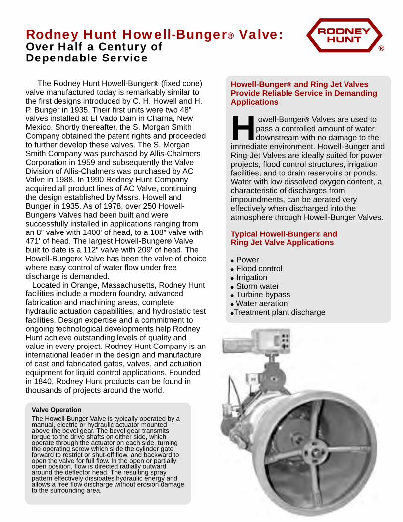
®
The Rodney Hunt Howell-Bunger (fixed cone) valve manufactured today is remarkably similar to the first designs introduced by C. H. Howell and H. P. Bunger in 1935. Their first units were two 48” valves installed at El Vado Dam in Charna, New Mexico. Shortly thereafter, the S. Morgan Smith Company obtained the patent rights and proceeded to further develop these valves. The S. Morgan Smith Company was purchased by Allis-Chalmers Corporation in 1959 and subsequently the Valve Division of Allis-Chalmers was purchased by AC Valve in 1988. In 1990 Rodney Hunt Company acquired all product lines of AC Valve, continuing the design established by Mssrs. Howell and Bunger in 1935. As of 1978, over 250 Howell-Bunger Valves had been built and were successfully installed in applications ranging from an 8” valve with 1400' of head, to a 108” valve with 471' of head. The largest Howell-Bunger Valve built to date is a 112” valve with 209' of head. The Howell-Bunger Valve has been the valve of choice where easy control of water flow under free discharge is demanded. Located in Orange, Massachusetts, Rodney Hunt facilities include a modern foundry, advanced fabrication and machining areas, complete hydraulic actuation capabilities, and hydrostatic test facilities. Design expertise and a commitment to ongoing technological developments help Rodney Hunt achieve outstanding levels of quality and value in every project. Rodney Hunt Company is an international leader in the design and manufacture of cast and fabricated gates, valves, and actuation equipment for liquid control applications. Founded in 1840, Rodney Hunt products can be found in thousands of projects around the world.
®
®
®
®
Rodney Hunt Howell-Bunger Valve:®Over Half a Century ofDependable Service
owell-Bunger Valves are used to pass a controlled amount of water Hdownstream with no damage to the
immediate environment. Howell-Bunger and Ring-Jet Valves are ideally suited for power projects, flood control structures, irrigation facilities, and to drain reservoirs or ponds. Water with low dissolved oxygen content, a characteristic of discharges from impoundments, can be aerated very effectively when discharged into the atmosphere through Howell-Bunger Valves.
! Power! Flood control! Irrigation! Storm water! Turbine bypass! Water aeration!Treatment plant discharge
Howell-Bunger and Ring Jet Valves Provide Reliable Service in Demanding Applications
Typical Howell-Bunger and Ring Jet Valve Applications
®
®
®
Valve Operation
The Howell-Bunger Valve is typically operated by a manual, electric or hydraulic actuator mounted above the bevel gear. The bevel gear transmits torque to the drive shafts on either side, which operate through the actuator on each side, turning the operating screw which slide the cylinder gate forward to restrict or shut-off flow, and backward to open the valve for full flow. In the open or partially open position, flow is directed radially outward around the deflector head. The resulting spray pattern effectively dissipates hydraulic energy and allows a free flow discharge without erosion damage to the surrounding area.
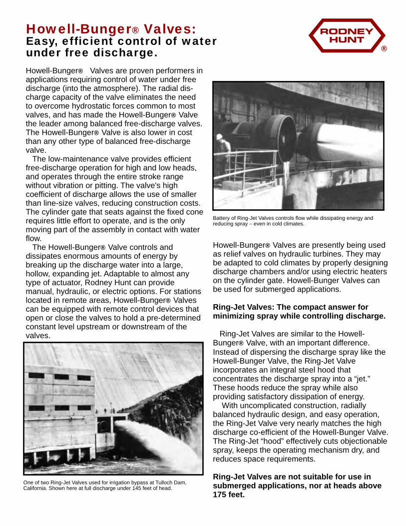
®
Howell-Bunger Valves are proven performers in applications requiring control of water under free discharge (into the atmosphere). The radial dis-charge capacity of the valve eliminates the need to overcome hydrostatic forces common to most valves, and has made the Howell-Bunger Valve the leader among balanced free-discharge valves. The Howell-Bunger Valve is also lower in cost than any other type of balanced free-discharge valve. The low-maintenance valve provides efficient free-discharge operation for high and low heads, and operates through the entire stroke range without vibration or pitting. The valve's high coefficient of discharge allows the use of smaller than line-size valves, reducing construction costs. The cylinder gate that seats against the fixed cone requires little effort to operate, and is the only moving part of the assembly in contact with water flow. The Howell-Bunger Valve controls and dissipates enormous amounts of energy by breaking up the discharge water into a large, hollow, expanding jet. Adaptable to almost any type of actuator, Rodney Hunt can provide manual, hydraulic, or electric options. For stations located in remote areas, Howell-Bunger Valves can be equipped with remote control devices that open or close the valves to hold a pre-determined constant level upstream or downstream of the valves.
®
®
®
®
®
Howell-Bunger Valves:®Easy, efficient control of water under free discharge.
One of two Ring-Jet Valves used for irrigation bypass at Tulloch Dam, California. Shown here at full discharge under 145 feet of head.
Howell-Bunger Valves are presently being used as relief valves on hydraulic turbines. They may be adapted to cold climates by properly designing discharge chambers and/or using electric heaters on the cylinder gate. Howell-Bunger Valves can be used for submerged applications.
Ring-Jet Valves: The compact answer forminimizing spray while controlling discharge.
Ring-Jet Valves are similar to the Howell-Bunger Valve, with an important difference. Instead of dispersing the discharge spray like the Howell-Bunger Valve, the Ring-Jet Valve incorporates an integral steel hood that concentrates the discharge spray into a “jet.” These hoods reduce the spray while also providing satisfactory dissipation of energy. With uncomplicated construction, radially balanced hydraulic design, and easy operation, the Ring-Jet Valve very nearly matches the highdischarge co-efficient of the Howell-Bunger Valve. The Ring-Jet “hood” effectively cuts objectionable spray, keeps the operating mechanism dry, and reduces space requirements.
Ring-Jet Valves are not suitable for use in submerged applications, nor at heads above 175 feet.
®
®
Battery of Ring-Jet Valves controls flow while dissipating energy and reducing spray – even in cold climates.
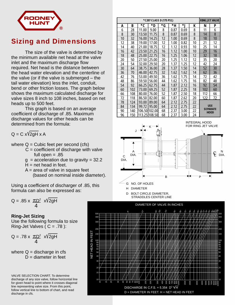
”8
”21
”81
”02
”42
”03
”63
”24
”84
”45
”06
”66
”27
”87
”48
”09”69”201”801500
400
300
200
150
10090807060
50
40
30
20
15
10
500
400
300
200
150
10090807060
50
40
30
20
15
10
DIAMETER OF VALVE IN INCHES
NE
T H
EA
D IN
FE
ET
D = DIAMETER IN FEET. H = NET HEAD IN FEET
10 15 20 30 40 50 60 70 80 90 100
150
200
300
400
500
600
700
800
900
1000
1500
2000
3000
4000
5000
6000
7000
8000
9000
1000
0
®
RING JET VALVE
A6810121416182024303642485460667278849096
B2830323840424850546470768692102108118124134140150
* C11.0013.5016.0019.0021.0023.5025.0027.5032.0038.7546.0053.0059.5066.2573.0080.0086.5093.0099.72106.50113.25
* D9.0011.7514.2517.0018.7521.2522.7525.0029.5036.0042.7549.5056.0062.7569.2576.0082.0089.0095.00102.00108.50
* G8812121216162020283236444452526064646868
* H0.870.871.001.001.121.121.251.251.371.371.621.621.621.871.871.871.872.122.122.372.37
* J0.690.690.690.820.931.001.061.121.251.501.621.751.752.122.252.502.622.752.753.003.00
P68
101214161820243036424854606672
* C207 CLASS D (175 PSI.)
USESEPARATE
HOOD
N1114182125293235425262728292
102112122
K888101010121212141414161618182022222224
Sizing and Dimensions
The size of the valve is determined by the minimum available net head at the valve inlet and the maximum discharge flow required. Net head is the distance between the head water elevation and the centerline of the valve (or if the valve is submerged – the tail water elevation) less the inlet, conduit, bend or other friction losses. The graph below shows the maximum calculated discharge for valve sizes 8 inch to 108 inches, based on net heads up to 500 feet.
This graph is based on an average coefficient of discharge of .85. Maximum discharge values for other heads can be determined from the formula:
Q = C x 2gH x A
where Q = Cubic feet per second (cfs) C = coefficient of discharge with valve
full open = .85g = acceleration due to gravity = 32.2H = net head in feet.A = area of valve in square feet (based on nominal inside diameter).
Using a coefficient of discharger of .85, this formula can also be expressed as:
2pQ = .85 x D x 2gH4
Ring-Jet Sizing Use the following formula to sizeRing-Jet Valves ( C = .78 ):
2pQ = .78 x D x 2gH4
where Q = discharge in cfsD = diameter in feet
CL
KJ
B P
G NO. OF HOLESH DIAMETERD BOLT CIRCLE DIAMETER, STRADDLES CENTER LINE
CDIA.
ADIA.
NDIA.
INTEGRAL HOODFOR RING JET VALVE
VALVE SELECTION CHART. To determine discharge of any size valve, follow horizontal line for given head to point where it crosses diagonal line representing valve size. From this point, follow vertical line to bottom of chart, and read discharge in cfs.

APPENDIX DPreliminary Technical Specifications List
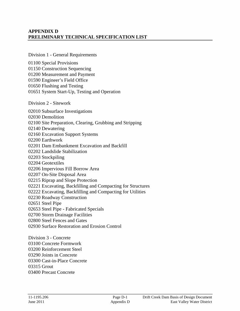
11-1195.206 Page D-1 Drift Creek Dam Basis of Design Document June 2011 Appendix D East Valley Water District
APPENDIX D PRELIMINARY TECHNICAL SPECIFICATION LIST Division 1 - General Requirements
01100 Special Provisions 01150 Construction Sequencing 01200 Measurement and Payment 01590 Engineer’s Field Office 01650 Flushing and Testing 01651 System Start-Up, Testing and Operation Division 2 - Sitework
02010 Subsurface Investigations 02030 Demolition 02100 Site Preparation, Clearing, Grubbing and Stripping 02140 Dewatering 02160 Excavation Support Systems 02200 Earthwork 02201 Dam Embankment Excavation and Backfill 02202 Landslide Stabilization 02203 Stockpiling 02204 Geotextiles 02206 Impervious Fill Borrow Area 02207 On-Site Disposal Area 02215 Riprap and Slope Protection 02221 Excavating, Backfilling and Compacting for Structures 02222 Excavating, Backfilling and Compacting for Utilities 02230 Roadway Construction 02651 Steel Pipe 02653 Steel Pipe - Fabricated Specials 02700 Storm Drainage Facilities 02800 Steel Fences and Gates 02930 Surface Restoration and Erosion Control Division 3 - Concrete 03100 Concrete Formwork 03200 Reinforcement Steel 03290 Joints in Concrete 03300 Cast-in-Place Concrete 03315 Grout 03400 Precast Concrete

11-1195.206 Page D-2 Drift Creek Dam Basis of Design Document June 2011 Appendix D East Valley Water District
Division 4 - Masonry
04100 Mortar and Grout Division 5 - Metals
05500 Metal Fabrications Division 6 - Wood and Plastics
06050 Fasteners and Adhesives 06100 Rough Carpentry Division 7 - Thermal and Moisture Protections
07920 Sealants and Caulking Division 8 – NOT USED Division 9 - Finishes
09800 Protective Coatings Division 10 - NOT USED Division 11 - Equipment
11000 Equipment, General 11101 Hydraulic Valve Operating System 11112 Intake Screens and Air Backwash System 11200 Miscellaneous Operations and Control Building Equipment 11900 Fall Prevention System Division 12 - NOT USED Division 13 - NOT USED Division 14 - NOT USED Division 15 - Mechanical
15000 Piping, General 15100 Valves, General 15103 Control Valves 15107 Miscellaneous Valves 15156 Sluice Gates Division 16 - Electrical 16010 Electrical - General Provisions

11-1195.206 Page D-3 Drift Creek Dam Basis of Design Document June 2011 Appendix D East Valley Water District
16100 Electrical - Basic Materials and Methods 16200 Electrical - Standby Generator 16400 Electrical - Service and Distribution 16500 Electrical - Lighting Division 17 - Instrumentation 17100 Instrumentation and Control System

APPENDIX ECommon Abbreviations

11-1195.206 Page E-1 Drift Creek Dam Basis of Design Document June 2011 Appendix E East Valley Water District
APPENDIX E COMMON ABBREVIATIONS AF Acre Feet ADD Average Daily Demand BA Biological Assessment BLM Bureau of Land Management BO Biological Opinion BOR Bureau of Reclamation cfs cubic feet per second COE Corps of Engineers CWA Clean Water Act DEQ Department of Environmental Quality DSL Division of State Lands EPA Environmental Protection Agency ESA Endangered Species Act EVWD East Valley Water District FERC fps
Federal Energy Regulatory Commission feet per second
gpcd gallons per capita day gpm gallons per minute HP Horsepower IFIM Instream Flow Incremental Methodology MDD Maximum Daily Demand MG Million Gallons mgd million gallons per day NEPA National Environmental Policy Act NOAA-Fisheries National Oceanic and Atmospheric Administration - Fisheries OAR Oregon Administrative Rules ODFW Oregon Department of Fish and Wildlife OEDD Oregon Economic Development Department OHD Oregon Health Division ORS Oregon Revised Statutes OWRD Oregon Water Resources Department RCC Roller Compacted Concrete RM River Mile SDWA Safe Drinking Water Act S,T,E Sensitive, Threatened and Endangered TMDL Total Maximum Daily Load UGB Urban Growth Boundary USFWS United States Fish and Wildlife Service USGS United States Geological Survey WTP Water Treatment Plant

APPENDIX FReferences
11-1195.206 Page F-1 Drift Creek Dam Basis of Design Document June 2011 Appendix F East Valley Water District
APPENDIX F REFERENCES 2006 Environmental Summary Report, Drift Creek Dam and Reservoir Project, Marion
County, Oregon, Northwest Environmental and Energy Professionals, October 2006. Cultural Resources of the Proposed Drift Creek Reservoir, Marion County, Oregon, Dr.
Robert W. Keeler, PhD, December 11, 2006. Dam Safety in Oregon – A General Guide, Oregon Water Resources Department, March
2007. Determination of Appropriate Ecological and Channel Maintenance Flows for Drift Creek
Downstream of the Proposed Dam, Ellis Ecological Services, Inc., March 2010. Drift Creek Reservoir and Dam – Geotechnical Reconnaissance, Siemens & Associates, July
24, 2009. Drift Creek Reservoir Model – Model Development and Scenarios Report, Portland State
University Drift Creek Water Supply Project – Preliminary Transmission Pipeline Routing Analysis
Technical Memorandum, Murray, Smith & Associates, Inc., October 2008. Engineering Geologic Information for Feasibility of Proposed Drift Creek Dam, H.G.
Schlicker & Associates, Inc., June 24, 2005. Hydrometeorological Report No. 57 Probable Maximum Precipitation – Pacific Northwest
States, National Weather Service, October 1994. Initial Feasibility Report, Stuntzner Engineering & Forestry, LLC, July 2, 2005. Oregon Guidelines for Timing of In-water Work to Protect Fish and Wildlife Resources,
Oregon Fish and Wildlife, June, 2008. Overall Project Planning Assessment/Water Conveyance System Alternatives Analysis, Final
Report Technical Memorandum, Murray, Smith & Associates, Inc., February 23, 2007 Runoff Yield Analysis for Drift Creek Site “A” Near Silverton, Oregon, Dr. Bolyvong
Tanovan, PhD, P.E., February 2007. Runoff Yield Analysis for Drift Creek Site “A” Near Silverton, Oregon (Update #1), Dr.
Bolyvong Tanovan, PhD, P.E., May 2010.

11-1195.206 Page F-2 Drift Creek Dam Basis of Design Document June 2011 Appendix F East Valley Water District
Runoff Yield Analysis for Drift Creek Site “A” Near Silverton, Oregon (Update #2), Dr.
Bolyvong Tanovan, PhD, P.E., February 2011. Stage-Storage Evaluation, Stuntzner Engineering & Forestry, LLC, March 23, 2007.

121 S.W. Salmon, Suite 900 Portland, Oregon 97204-2919 www.msa-ep.com