attachment 2 to aep:nrc:3054-07 implementing …
TRANSCRIPT
ATTACHMENT 2 TO AEP:NRC:3054-07
IMPLEMENTING PROCEDURES
PMI-2080, Revision 7
PMP-2080-EPP-100, Revision 1
PMP-2080-EPP-101, Revision 3b
PMP-2080-EPP-107, Revision 17
PMP-2080-EPP-108, Revision 4
PMP-2081-EPP-105, Revision 4
RMT-2080-EOF-001, Revision 3
RMT-2080-EOF-002, Revision 1
RMT-2080-OSC-001, Revision 2
RMT-2080-TSC-001, Revision 2

REVIEW AND APPROVAL TRACKING FORM
Proedure Information:Number: PMI-2080 Rev. 7 Change: 0
Title: Emergency Plan and Implementing Procedures
Categor (Select' One"Only): 1 Correction (Full Procedure) 1 Change (Full Procedure) with Review of Change OnlyEj Correction (Page Substitution) O Change (Page Substitution) with Review of Change OnlyO Cancellation O New Procedure or Change with Full ReviewO Superseded (list superseding procedures):
Associated Configuration Impact Assessments:,
Change Driver/CDI Tracking No(s).: ___ N/A
RequiedlReviews:
Cross-Discipline Reviews: Programmatic Reviews:X Chemistry 1 Training 1 ALARA 1 Reactivity Mgmt Team
3 Maintenance 1 Work Control 13 Component Engineering 1 SPS (Safety & Health)1 NDM 13 Design Engineering 1 Surveillance Section
| Operations 13 E1 Emerg Oper Proc Grp 1 System Engineering
1 PA/PV 1 1 Environmental 1 SOMS Administrator1 Reg Affairs 13 ISI/IST Coordinator 13 RP 13 None Required | Performance Assurance 13 None Required
Z Cognizant Org Review: Date: / I_
E Technical Review: - Date: / /
Concurrence:i>- u'i',00'4''" < -4-l'''0t-S'-0$ 'S+'f5
1 Ops Director Concurrence: N/A Date: II
Package Check: "Updated Revision Summary attached? 1 Yes10 CFR 50.59 Requirements complete? Tracking No.:2003-0361-00 | Yes 1 N/AImplementation Plan developed? (Ref. Step 3.4.17) | Yes O N/APackage Complete: Date: / I
Approv Ils:''--X3--fw0R 0PI
PORC Review Required: 3 Yes 1 No Mtg. No.:_ _
Administrative Hold Status: 13 Released F1 Reissued Z N/A CR No.:_
Approval Authority Review/Approval: Date: _ I_-
Expiration Date/Ending Activity Effective Date: / /Periodic Review: " Tj
Periodic Review conducted? (Data Sheet 5 Complete) 13 Yes 3 No
Flow-up Actions:^'jCommitment Database update requested in accordance with PMP-7100-CMP-001? F-1 Yes [O N/ANDM notified of new records or changes to records that could affect record retention? 13 Yes 1 N/A
ofr iice IformtionFor Form rac g Oly- Part of
This form is derived from the information in PMP-2010-PRC-002,Procedure Correction, Change, and Review, Rev. 10a, Data Sheet 1,
z Review and Approval Tracking Form. Page _ of

REVIEW AND APPROVAL TRACKING FORM
Number: PAMI-2080 Rev. 7 . Change:. 0
Title: Emer*t encvPlan andlmplemenltiflProcedures
E Correction (Full Procedure) 0 Change (Full Procedure) with Review of Change Only] Correction (Page Substitution) .0 Change (Page Substitution) with Review of Change Only
El Cancellation . New Procedure or Change with Full Reviewo Superseded (list superseding procedures):
Change Driver/CD1 Trackdng No(s).: - ON/A54TRiPe,!gI 11 19 R. , l ;. V N` Eg V Rm63
Cross-Discipline Reviews: Programmatic Reviews:X Chemistry 0 Training ALARA Reactivity Mgmt Team0 Maintenance Ol Work Control - Component Engineering -f SPS (Safety & Health)El NDM O - 0 Design Engineering . Surveillance Section0 Operations E__ _ Emerg Oper Proc Grp E System EngineeringEl PA/PV _ 0 Environmental O SOMS AdministratorO Reg Affairs El ISIJIST Coordinator .0 RP E None Required El Performance Assurance .. None Required
I Cognizant Org Review: <A Date: q 11100
[ p T echnicalRview: n. / Date: 1 I,;11_
.El Ops Director Concuffence: N/A : - Date: _
Updated Revision Summary attached?10 CER 50.59 Requiremenis complete?Implementation Plan developed?- _ . - . tR
Commitment Database update requested in accordance with PMP-7100-CMP001? - 0 YesNDM notified of new records or changes to records that could affect record retention? El Yes
I1-
:' .
.
:
>: .
:Toe L:
#,1,,144xca
.q1 16
.S,
- .
I
I
This form is derived from the Information in PMP-2010-PRC-002,Procedure Correction, Change, and Review, Rev. 10a, Data Sheet 1,Review and Approval Tracking Form. . Page ( of__
tJa3EA:gS1Z'Xg~~~~~~~~~~~~~~~~~~~~~~~~
r 14 f 'r ,n i_,r _

REVISION SUMMARY
Number: PMI-2080Title: Emer2enc
Revision: 7 Change: 0v Plan Implementing Procedures
Section or Step Change/Reason For Change
Marginal Markings not used due to the nature of the changes (table).The Implementation Plan for this revision is the Implementation Planfor Revision 18 of the Emergency Plan.
Step 5.2.1 Change: Added reference to the Emergency Plan
Reason: The Emergency Plan -is the governing document for thisprocedure.
Attachment 1 Change: The following changes were made to the staffing requirementstable based on NRC approval of Revision 18 of the EmergencyPlan:
On Shift Column
Changed Core and Thermal Hyd on shift person to STA, added 1* formanning column. Moved Unit Supervisors to Plant Operations.
Electrical Maintenance - added 1
I&C Maintenance - deleted 1
Radiological Waste - deleted 1
Protective actions - added 1
Plant Operations - moved Unit Supervisor to Plant Operations
On site (out of plant) - deleted 1
In plant surveys - deleted 1
60 Minute Column
Added PET-Ops/Training - 1
AEO - added 1
RP Technicians (protective actions) - deleted 2
Reason: 30 minutes response column requirements were deleted withthe approval of Revision 18 to the Emergency Plan.
Attachment 1 Change: Deleted the '30 minutes' and the ** from the table header.
Reason: 30 minutes response column requirements were deleted withthe approval of Revision 18 to the Emergency Plan.
Page _ of _
~~ ~ ~ OfficeA Inomto orFr rcin ny otPr fFrThis is a free-form as called out in PMP-2010-PRC-002, Procedure Correction,Change, and Review, Rev. 10a.

REVISION SUMMARY
Number: PMI-2080
Title: Emergenc
Revision: 7 Change: 0
y Plan Implementing Procedures
Section or Step Change/Reason For Change
Attachment 1 Change: Deleted the *** from the Offsite surveys RP Technician.
Reason: 30 minutes response column requirements were deleted withthe approval of Revision 18 to the Emergency Plan.
Attachment 1 Change: Changed the total on site personnel to 23.
Reason: 30 minutes response column requirements were deleted withthe approval of Revision 18 to the Emergency Plan.
Attachment 1 Change: Replaced the ** note reference to 30 minute staffingrequirements with the note for personnel performing otherfunctions.
Reason: 30 minutes response column requirements were deleted withthe approval of Revision 18 to the Emergency Plan.
Attachment 1 Change: Added the third note (***) to explain the I&C and Electricianrequirements.
Reason: 30 minutes response column requirements were deleted withthe approval of Revision 18 to the Emergency Plan.
Change:
Reason:
00 k OffieIformation o FoTrackin Oni-Not Part of Form' -. <vThis is a free-form as called out in PMP-2010-PRC-002, Procedure Correction,Change, and Review, Rev. 10a. Page _ of

ELEMORC PMI-2080 Rev. 7 Page 1 of 9
Emergency Plan and Implementing Procedures
Information Effective Date: /
B. K. Molloy S. M. Partin Emergency PlanningWriter Owner Cognizant Organization
TABLE OF CONTENTS
1 PURPOSE AND SCOPE .2
2 DEFINITIONS AND ABBREVIATIONS. 2
3 DETAILS. 2
4 FINAL CONDITIONS. 5
5 REFERENCES. 6
Attachment 1: Emergency Plan Staffing Requirements .......................................... 7
Figure 1: Cook Plant Emergency Preparedness Advisory Committee ................. 9

Information I PMI-2080 I Rev. 7 1 Pa e 2 of 9
Emergency Plan and Implementing Procedures
1 PURPOSE AND SCOPE
1.1 To establish the administrative controls for protecting the health and safety of thegeneral public and Nuclear Generation Group (NGG) personnel during radiologicalemergencies at the Donald C. Cook Nuclear Plant.
1.2 To provide the assignment of supervisory responsibilities for the implementation ofthese administrative controls.
1.3 To detail the minimum on-shift Emergency Plan staffing requirement.
2 DEFINITIONS AND ABBREVIATIONS
3
3.1
DETAILS
An Emergency Plan and Emergency Plan Procedures shall be developed for all areasof emergency planning as identified in 10 CFR 50, Appendix E.
3.1.1 Those areas covered by the Emergency Plan shall include, but are notlimited to the following:
a. Organization
b. Assessment actions
Term Meaning
EPAC Emergency Preparedness Advisory Committee
EPM Emergency Planning Manager
ERO Emergency Response Organization
NGG Nuclear Generation Group
NRC Nuclear Regulatory Commission
On-Shift Personnel Personnel are on-site at all times.
PORC Plant Operations Review Committee
Information I PMI-2080 I Rev. 7 l Page 3 of 9
Emergency Plan and Implementing Procedures
c. Activation of emergency organizations
d. Notification procedures
e. Emergency facilities and equipment
f. Training
g. Maintaining emergency preparedness
h. Recovery
3.2 An Emergency Response Organization (ERO) shall be established, with trained andequipped personnel, to respond to actual or potential radiological emergencies at theCook Nuclear Plant.
3.3 The Donald C. Cook Emergency Plan and Emergency Plan Procedures shall meet thestandards as set forth in 10 CFR 50.47(b), and ANSI N18.7 - 1976/ANSI 3.2,Section 5.3.9.3. As a minimum the Emergency Plan and, as appropriate, EmergencyPlan Procedures, shall address the following as specified in 10 CFR 50.47.
3.3.1 Assignment of responsibilities to NGG, the State of Michigan and BerrienCounty shall be documented.
3.3.2 The responsibilities of on-shift personnel.
3.3.3 Shift staffing requirements to ensure that an adequate accident responsecapability exists at all times. The capability to augment on-shift capabilitiesin a timely manner shall also be specified. Attachment 1, Emergency PlanStaffing Requirements, contains the minimum staffing requirements.
3.3.4 Arrangements for requesting and effectively utilizing off-site resources.
3.3.5 A standard emergency classification and action level scheme which shall becoordinated with state and county response plans.
3.3.6 Procedures for notification of state and county response organizations aswell as NGG emergency response personnel.
3.3.7 Communications capabilities which facilitate prompt communications amongprincipal response organizations and to the public.
3.3.8 Methods for the dissemination of information to the general public on aperiodic basis prior to an emergency.

Information T PMI-2080 _ Rev. 7 | Page 4 of 9
Emergency Plan and Implementing Procedures
3.3.9 Requirements for the provision and maintenance of emergency responsefacilities.
3.3.10 Methods, systems and equipment for assessing and monitoring actual orpotential off-site consequences of a radiological emergency.
3.3.11 A range of protective actions and guidelines for the choice of appropriateoff-site protective actions consistent with federal guidance.
3.3.12 Methods shall be established for controlling the radiological exposure ofemergency workers.
3.3.13 Arrangements for medical services for contaminated injured individuals.
3.3.14 General plans for recovery and re-entry.
3.3.15 Guidance concerning periodic drills and exercises.
3.3.16 Provisions for radiological emergency response training for those who maybe called upon to assist in an emergency.
3.3.17 Responsibilities for plan and procedure development review, revision anddistribution.
3.4 The Donald C. Cook Emergency Plan shall provide for agreements of assistance withoff-site fire departments.
3.5 Changes may be made to the Donald C. Cook Emergency Plan without NRCapproval only if such changes do not decrease the effectiveness of the plan and theplan as changed, continues to meet the standards of 10 CFR 50.47(b), (d), and therequirements for 10 CFR 50, Appendix E (10 CFR 50.54(q)).
3.5.1 The EPM shall determine the extent of change and if a request for NRCapproval is required.
3.5.2 All changes to the Emergency Plan shall be made available to the NRC forpurposes of information and emergency preparedness.
3.6 The Emergency Plan and Emergency Plan Procedures shall provide for a programthat ensures the capability to accurately determine the airborne iodine concentrationin areas in the plant where personnel may be present during an emergency. Thisprogram shall include training of personnel in accordance with TPD-600-EPT,procedures for monitoring, and provisions for maintenance of sampling and analysisequipment.
Information PMI-2080 I Rev. 7
Emergency Plan and Implementing Procedures
Page of 9
3.7 Emergency Plan records shall be prepared and retained as authorized in PMI-2030.
3.8 The Site Vice President's responsibility for the following plant emergency planningduties is delegated to the EPM:
3.8.1 Maintaining the Emergency Plan procedures, facilities and training.
3.8.2 Interfacing with state and local agencies on Emergency Planning issues.
3.9 An EPAC shall be established to create scenarios for and conduct Emergency Plandrills and exercises.
3.9.1 The EPAC is responsible for the evaluation of those drills and exercises andmaking recommendations for improvements to the EPM.
3.9.2 The EPAC shall meet on an as-needed basis or at the request of the EPM orthe Emergency Planning Coordinators.
3.9.3 The committee shall be organized as illustrated in Figure 1, Cook PlantEmergency Preparedness Advisory Committee. The EPAC members shallbe chosen by the EPM.
3.10 Plant line management is responsible for supporting the Emergency Plan program andactivities.
3.11 The Site Vice President, or designee, will review the critiques of all emergency drillsand exercises.
3.12 The PORC will review changes to the Emergency Plan.
3.13 The EPM or designee will review the Emergency Plan Procedures annually.
3.14 The EPM will review proposed changes to facilities and equipment affecting theERO's functional capabilities.
3.15 The Senior Vice President - NGG, or his designee, is responsible for reviewing allchanges to the Emergency Plan.
4 FINAL CONDITIONS
None
I
I
Information | PMI-2080 Rev. 7 Page 6 of 9
Emergency Plan and Implementing Procedures
5 REFERENCES
5.1 Use References:
5.1.1 ANSI N18.7 - 1976, Administrative Controls and Quality Assurance for theOperations Phase of Nuclear Power Plants.
5.1.2 10 CFR 50, Appendix E, Emergency Planning and Preparedness forProduction and Utilization Facilities.
5.1.3 TPD-600-EPT, Emergency Plan Training Program Description
5.1.4 PMI-2030, Nuclear Document Management
5.2 Writing References:
5.2.1 Source References:
a. 10 CFR 50.47, Emergency Plans
b. 10 CFR 50.48(b), Fire Protection
c. AEP:NRC:9264
5.2.2 General References
a. Regulatory Guide 1.33, Quality Assurance Program Requirements(Operation)
b. Unit 1 Operating License, Section 2.1, Iodine Monitoring
c. Unit 2 Operating License, Section 2.11, Iodine Monitoring
d. 10 CFR 50.54(q)
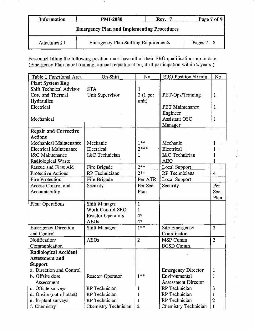
Personnel filling the following position must have all of their ERO qualifications up to date.(Emergency Plan initial training, annual requalification, drill participation within 2 years.)
Table 1 Functional Area On-Shift No. ERO Position 60 min. No.Plant System EngShift Technical Advisor STA 1Core and Thermal Unit Supervisor 2 (1 per PET-Ops/Training 1Hydraulics unit)Electrical PET Maintenance 1
EngineerMechanical Assistant OSC 1
ManagerRepair and CorrectiveActionsMechanical Maintenance Mechanic 1** Mechanic 1Electrical Maintenance Electrical 2*** Electrical 1I&C Maintenance I&C Technician 1 I&C Technician 1Radiological Waste AEO 1Rescue and First Aid Fire Brigade 2** Local SupportProtective Actions RP Technicians 2** RP Technicians 4Fire Protection Fire Brigade Per ATR Local SupportAccess Control and Security Per Sec. Security PerAccountability Plan Sec.
PlanPlant Operations Shift Manager 1
Work Control SRO 1Reactor Operators 4*AEOs 4*
Emergency Direction Shift Manager 1** Site Emergency 1and Control CoordinatorNotification/ AEOs 2 MSP Comm. 2Communication BCSD Comm.Radiological AccidentAssessment andSupporta. Direction and Control Emergency Director 1b. Offsite dose Reactor Operator 1** Environmental 1
Assessment Assessment Directorc. Offsite surveys RP Technician 1 RP Technician 3d. Onsite (out of plant) RP Technician 1 RP Technician 1e. In-plant surveys RP Technician 1 RP Technician 2f. Chemistry Chemistry Technician 2 Chemistry Technician 1
Information PMI-2080 I Rev. 7 Page 7 of 9
Emergency Plan and Implementing Procedures
Attachment 1 Emergency Plan Staffing Requirements Pages 7 - 8
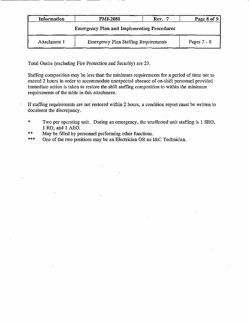
Total Onsite (excluding Fire Protection and Security) are 23.
Staffing composition may be less than the minimum requirements for a period of time not toexceed 2 hours in order to accommodate unexpected absence of on-shift personnel providedimmediate action is taken to restore the shift staffing composition to within the minimumrequirements of the table in this attachment.
If staffing requirements are not restored within 2 hours, a condition report must be written todocument the discrepancy.
* Two per operating unit. During an emergency, the unaffected unit staffing is 1 SRO,1 RO, and 1 AEO.
** May be filled by personnel performing other functions.*** One of the two positions may be an Electrician OR an I&C Technician.
Information | PMI-2080 I Rev. 7 _ Page 8 of 9
Emergency Plan and Implementing Procedures
Attachment I Emergency Plan Staffing Requirements Pages 7 - 8

EMERGENCY PLANNINGMANAGER
�*1*
RADIATIONPROTECTIONADVISOR
CHEMISTRYADVISOR
SITE PROTECTIVESERVICES ADVISOR
SIMULATORINSTRUCTORS
OPERATIONSADVISOR
- n
FACILITYCONTROLLERS
Information PMI-2080 Rev. 7 | Page 9 of 9
Emergency Plan and Implementing Procedures
Figure 1 Cook Plant Emergency Preparedness Advisory Page 91 ~~~~~~~~Committee Pg
EMERGENCY PLANNINGCOORDINATORS (4)
-
r
I

REVIEW AND APPROVAL TRACKING FORM
Wfmt* . T ..v ___ ~ T ._,-"Procedure Information.. >L<- 1 __~~~~~~ - _ - --- ' ~ -1
Number: PiMlP-2080-EPP-100
Title: Emergencv Response1 Change: 0
Catcory (Select One 0y[i Correction (Full Procedure) | CLi Correction (Page Substitution) l CO Cancellation Li NL Supersede.d (list superseding procedures):
'hange (Full Procedure) with Review of Change Only_hange (Page Substitution) with Review of Change Onlyrew Procedure or Change with Full Review
Associ3- _ ration ImpatW ~ -~ ~ i*
Change Driver/CDI Tracking No(s).: |g N/AReqired Rie~; s , - . _ -W _>.Reqluired Revlew;s: - ,>. . I-' K- a - ri- t ! - ~'~-lr
Cross-Discipline Reviews: Programmatic Reviews:l Chemistry Z Training O ALARA L Reactivity Mgmt Team
O Maintenance E Work Control L Component Engineering O SPS (Safety & Health)l NDM LI _ Design Engineering E] Surveillance Section
[I1 Operations L _ Emerg Oper Proc Grp L System Engineering
El PAIPV L V?is E Environmental O
L Reg Affairs l l I/ST Coordinator i t.,_
L RP L None Required El Performance Assurance Z None Required
3 Cognizant Org Review: Date: >/ 3 /tC5
3 Technical Review: . Date: /i I..]
Concurrence:. . - ;r... . z.. -:
El Ops Director Concurrence: N/A Date: / _
Package Check: -- - -
Updated Revision Summary attached? | Yes
10 CFR 50.59 Requirements complete? Tracking No.: 2003-0062-00 _ 1, Yes L N/A
Implementation Plan developed? ,. v Step 3.4.17) i Yes MN/A
Package Complete: _ _ _ __ D Date:/2 4!vd c3.~~~~~4. .___,_ _ 7§
Approva : - , . "2- <,"-.
PORC Review Required: 3 Yes a No Mtg. No.:iji1 YAdministrative Hold Status: L R sed [ .eissued 3 N/A CR No.:_
Approval Authority Review/Approva r- ¼e Date:2 __1L.1k3
Expiration Date/Ending Activity A Effective Date: 2 l.X' 0,j
Periodic Review..
Periodic Review conducted? (Data Sheet 5 Complete) l Yes Z No
FolloW-up Actions: .; ..
Commitment Database update requested in accordance with PMP-7100-CMP-001? 0 Yes ] N/A
NDM notified of new records or changes to records that could affect record retention? L Yes 1 N/A
Office Inf rmatlon o orm Tracing 6rfly - Not Part of Form.... :.< ,;.; -. ^,¢
This form is derived from the information in PMP-2010-PRC-002,Procedure Correction, Change, and Review, Rev. 10, Data Sheet 1.Review and Approval Tracking Form. Page of .3
Rev.
5v
z _
I
I

REVISION SUMiMARY
Number: PMP-2080-EPP-100
Title: Emergency Response
Revision: 1 Change: 0
Nv 4tI 4 6 .. .A ASection or Step I Change/Reason For Change
Step 3.2.3.b Change: Changed step to read 'direct an announcement to be made toevacuate the beach.' after THEN.
Reason: The recorded announcement capability for the beachevacuation system is not functional and obsolete. The changeallows the control room to make an announcement using thebeach PA system.
Section 3.2 Change: Added step 3.2.3.c to address off site agency personnel locatedon company property.
Reason: To ensure protective actions are addressed for off site agencypersonnel.
Step 3.2.6.b Change: Deleted the second 'Attention all personnel' frm theannouncement.
Reason: Eliminate redundancy.
Step 3.2.6.c Change: Deleted bullet to press ## to access the PA system.
Reason: Pressing ## is not necessary.
Step 3.2.7 Change: Moved step 3.2.7.b to 3.2.7.d and added '3.2.7.a' to the stepto describe a step reference and added 'that is provided to thestate' to the end of the step. Also renumbered sub-steps in3.2.7 to reflect the change in order.
Reason: To correctly describe the order the steps should be performedin and to clarify the step.
Step 3.2.7.c (old Change: Added title of Flowchart.
d) Reason: Conform to format. Correction: k
Step 3.2.7.e Change: Added EMD-32 as the form number, changed inform' to'notify' and added the reference to PMP-2080-EPP-107 at theend of the step.
Reason: Conform to format and clarify step. Correction: k, r
Section 3.2 Change: Added new Step 3.2.11 and renumbered remaining step inSection 3.2.
Reason: To prompt the SM to consider incoming plant personnel andany special instructions that may be necessary for theirprotection.
__lOfice Iiformation Foi`Foini.i' inj Only- Not Part6f Form -
This is a free-form as called out in PMP-2010-PRC-002, Procedure Correction,Change, and Rview, Rev. 10. Page J of3
REVISION SUIMIARY
Number: PMP-2080-EPP-100Title: Emergency Response
Revision: I Change: 0
Section or Sten Change/Reason For Change
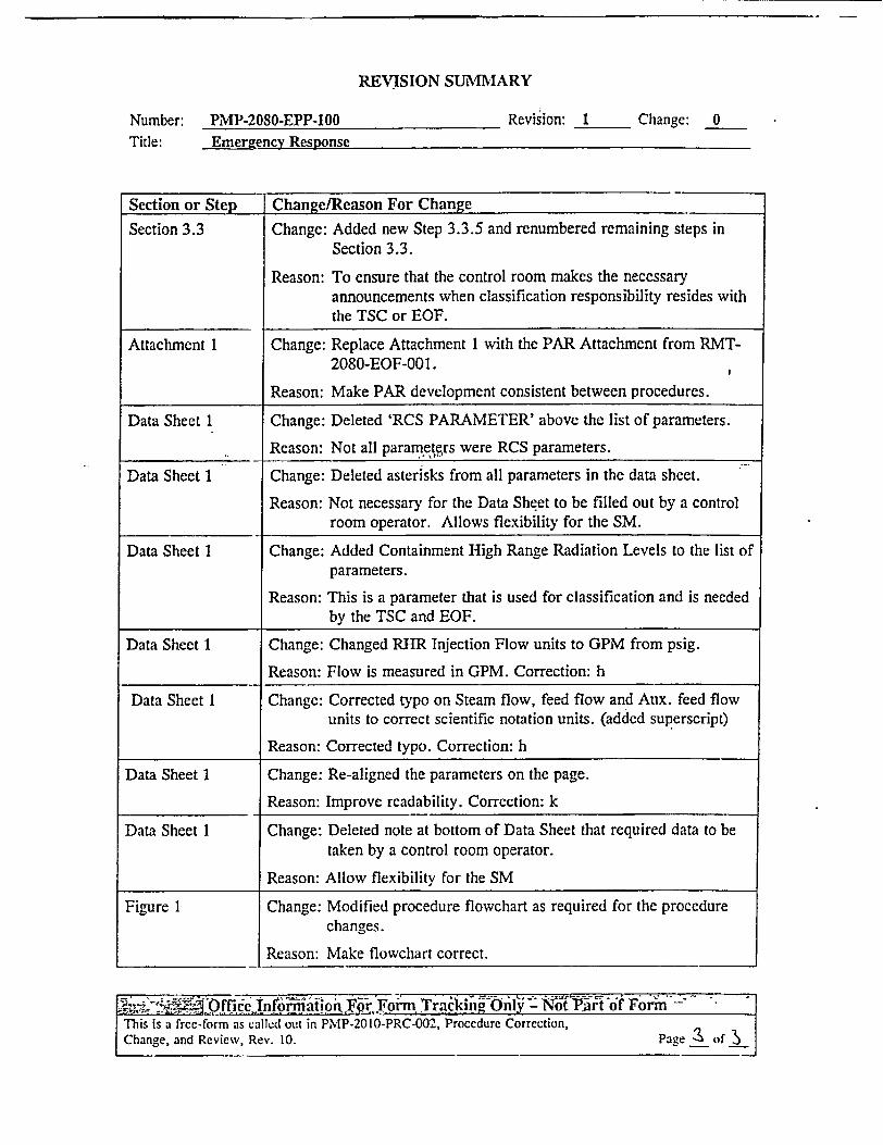
Section 3.3 Change: Added new Step 3.3.5 and renumbered remaining steps inSection 3.3.
Reason: To ensure that the control room makes the necessaryannouncements when classification responsibility resides withthe TSC or EOF.
Attachment 1 Change: Replace Attachment 1 with the PAR Attachment from RMT-2080-EOF-001.
Reason: Make PAR development consistent between procedures.
Data Sheet 1 Change: Deleted 'RCS PARAMETER' above the list of parameters.
Reason: Not all parameters were RCS parameters.
Data Sheet 1 Change: Deleted asterisks from all parameters in the data sheet.
Reason: Not necessary for the Data Sheet to be filled out by a controlroom operator. Allows flexibility for the SM.
Data Sheet 1 Change: Added Containment High Range Radiation Levels to the list ofparameters.
Reason: This is a parameter that is used for classification and is neededby the TSC and EOF.
Data Sheet 1 Change: Changed RHR Injection Flow units to GPM from psig.
Reason: Flow is measured in GPM. Correction: h
Data Sheet 1 Change: Corrected typo on Steam flow, feed flow and Aux. feed flowunits to correct scientific notation units. (added superscript)
Reason: Corrected typo. Correction: h
Data Sheet 1 Change: Re-aligned the parameters on the page.
Reason: Improve readability. Correction: k
Data Sheet I Change: Deleted note at bottom of Data Sheet that required data to betaken by a control room operator.
Reason: Allow flexibility for the SM
Figure 1 Change: Modified procedure flowchart as required for the procedurechanges.
Reason: Make flowchart correct.
This is a free-form as calie:d out in PMP-2010-PRC-002, Proccdurc Correction,Change, and Review, Rev. 10. Page of ___

IC:RKARmic PMIP-2080-EPP-100 Rev. 1 Page 1 of 21
Emergency Response
Reference Effective Date: .2 /'I 3
B. K. Molloy S. M. Partin Site Protective ServicesWriter Owner Cognizant Organization
TABLE OF CONTENTS
1 PURPOSE AND SCOPE ............................ 2
2 DEFINITIONS AND ABBREVIATIONS ................................. 2
3 DETAILS .................................... 3
4 FiNAL CONDITIONS ............................... 8
5 REFERENCES .......................................................................................... 8
Attachment 1:
Data Sheet 1:
Data Sheet 2:
Figure 1:
PAR Flowchart and Map ...................... 10
Technical Information Sheet ...................... 12
Emergency Turnover Checklist ...................... 14
Procedure Flowchart ...................... 18

Reference PMP-2080-EPP-100 I Rev. Page 2 of 21
Emergency Response
1 PURPOSE AND SCOPE
1.1 This procedure provides instructions to the Shift Manager acting as the SiteEmergency Coordinator (SEC), for implementing a response to an UnusualEvent (UE), Alert, Site Area Emergency (SAE) and General Emergency(GE) after an emergency has been declared.
1.2 The steps in this procedure are listed in the preferred order of performancefor maximum efficiency. However, the steps may be performed in adifferent sequence.
2 DEFINITIONS AND ABBREVIATIONS
Term Meaning
AOP Abnormal Operating Procedure
BCSD Berrien County Sheriff Department
DAP Dose Assessment Program
EMD-32 Nuclear Plant Accident Notification form
ENC Emergency News Center
EOF Emergency Operations Facility
EOP Emergency Operating Procedure
ERDS Emergency Response Data System
ERO Emergency Response Organization
GE General Emergency
JPIC Joint Public Information Center
MSP Michigan State Police
OSC Operations Support Center
PAR Protective Action Recommendation
PPC Plant Process Computer
SAE Site Area Emergency

Reference PMP-2080-EP ORev. 1 e3o 21
Emergency Response
SAS Secondary Alarm Station
SEC Site Emergency Coordinator
SM Shift Manager
TSC Technical Support Center
UE Unusual Event
NOTE: All procedure steps are applicable to all Emergency Classification LevelsEXCEPT when the applicable Emergency Classification Level(s) is(are)specified within a step. (Reference Figure 1, Procedure Flowchart.)
3 DETALS
3.1 General
3.1.1 IF a classification upgrade is required at any time while theprocedure is being performed or after it is completed, THENreturn to step 3.2, Instructions, and proceed through theprocedure again.
3.1.2 The Operations SM acting as the SEC shall implement thisprocedure until relieved of SEC duties.
3.1.3 The following actions shall not be delegated by the SEC:
• Classification of the emergency.
* Directing the notification of offsite officials.
* Approval of PAR to offsite emergency management agencies.
3.1.4 Declaration of an emergency requires the notification of theBCSD and MSP within 15 minutes. Notification of the NRCshall follow county and state notification and in all cases becompleted within one hour.
3.1.5 Declaration of a GE requires that a PAR be made to the state.The PAR should be made immediately after the notification of aGE (i.e., during the same phone call).

Reference PMP-2080-EPP-100 Rev. 1 Page 4 of 21
Emergency Response
3.1.6 The ERDS for the affected Unit must be operational andtransmitting data to the NRC within one hour of an ALERT orhigher declaration.
3.1.7 The OSC, TSC, and the EOF are required to be activated at anALERT classification or higher.
3.2 Instructions
3.2.1 Inform Unit I and Unit 2 Control Room personnel of the eventclassification and that the SM has assumed the position of SEC.
3.2.2 Implement or direct the implementation of PMP-2080-EPP-107,Notification.
3.2.3 IF a SAE or GE has been declared, THEN notify the SecurityShift Supervisor (x 2005 or 2731) to perforni accountability.
a. WHEN evacuation is necessary, THEN inform the SecurityShift Supervisor (x 2005 or 2731) to evacuate plantpersonnel.
b. WHEN evacuation of the beach is necessary, THEN directan announcement to be made to evacuate the beach.
c. IF offsite agency personnel (e.g., National Guard, MSP,etc.) are stationed in the owner-controlled area, THENdetermine if these personnel should be evacuated or if theywill remain onsite.
Take appropriate action (e.g., evacuate, shelter, relocateonsite, issue dosimetry, etc.) as necessary to protect theoffsite agency personnel.
3.2.4 IF a hazard to plant personnel exists (e.g., fire, radiation or toxicgas), THEN perform one of the following steps:
a. IF the condition is local, THEN evacuate the area by pageannouncement.
b. IF the condition impacts significant portions of the plant,THEN direct the Security Shift Supervisor (x 2005 or 2731)to perform accountability in accordance with Security PostOrders and perform an evacuation.

Reference l PMP-2080-EPP-100 1 Rev. I Page 5 of 21
Emergency Response
NOTE: The presence of an offsite dose rate may require re-classification of the eventin accordance with ECC R-1, Effluent Release, PMP-2080-EPP-101,Emergency Classification.
3.2.5 IF a gaseous release of radioactive material is occurring, THENinitiate use of the DAP, to determine the magnitude of offsitedose levels. The following Emergency Plan procedures should beused as appropriate:
PMP-2080-EPP-108, Initial Dose Assessment (for use in theControl Room).
* RMT-2080-EOF001, Activation and Operation of the EOF,1 (for use in the EOF).
3.2.6 IF additional personnel are required to respond to an UnusualEvent to support the emergency response, THEN:
a. Call the SAS (x 118) and direct security to implement theDialogic Emergency Response Notification System for anEMERGENCY.
b. Direct a Control Room Operator to make the followingannouncement for the appropriate ERO facility(s) to beactivated, over the PA system. Have the announcementbroadcast twice.
"Attention all personnel. The Unusual Event is still ineffect, however report to and activate the OperationsSupport Center/Technical Support CenterlEmergenayQperations Facilitv All other plant personnel be preparedfor further announcements."
c. On any touch-tone telephone:
Dial 1646
Wait for the tone
Repeat the above announcement twice

3.2.7 IF a GE has been declared, THEN direct the development of aProtective Action Recommendation using the following steps:
a. Prior to developing a PAR consider whether the followingcould have an effect on the PAR:
Adverse weather conditions.
A forecast of changing weather conditions.
Release characteristics (Puff vs. Continuous).
* Evacuation times.
b. Obtain the following data:
. Wind direction
- AND -
Offsite dose projection (if available) as calculated usingDAP or actual offsite dose rate measurements.
c. Using Attachment 1, PAR Flowchart and Map, determine theappropriate PAR.
d. Include any deviations from the PAR flowchart, Attachment1, based on step 3.2.7.a in the protective actionrecommendation that is provided to the state.
e. Enter the PAR on the EMD-32 form, Nuclear Plant AccidentNotification, obtained from the Emergency Kit and notify theState of Michigan of the recommendation within 15 minutes,in accordance with PMP-2080-EPP-107, Notification.
f. Repeat Steps 3.2.7.a through 3.2.7.e every 30 minutes orwithin 15 minutes of a PAR change until relieved by theincoming ERO.
3.2.8 Perform mitigating actions in accordance with appropriate plantprocedures.
3.2.9 IF the PPC is inoperable, THEN:

• Designate someone to complete Data Sheet 1, TechnicalInformation Sheet, every 15 minutes.
• Forward the completed copy to the TSC.
* Continue this activity for the duration of the emergency oruntil the PPC is operable.
3.2.10 IF accountability results identify a missing person(s) AND theTSC and OSC are NOT activated, THEN have Security attemptto locate the missing person(s).
3.2.11 Determine if special directions to the Security Staff are required(e.g., security event, radiation release, etc.) in order to controlincoming ERO and/or non-ERO plant staff.
Provide directions as necessary to control incomingpersonnel.
3.2.12 Upon arrival of the oncoming SEC conduct a turnover as follows:
a. Obtain a copy of Data Sheet 2, Emergency TurnoverChecklist.
b. Have the oncoming SEC complete the checklist as each itemis verbally addressed.
3.3 Subsequent Instructions for the SM After Being Relieved of SEC Duties
3.3.1 WHEN relieved of SEC responsibilities, THEN resume the solefunction of SM.
Notify the Control Rooms that the SM has been relieved ofSEC responsibilities.
3.3.2 Direct the continued implementation of the appropriateEmergency Operating Procedure (EOP) and/or AbnormalOperating Procedure (AOP) to return the unit to a safe condition.
3.3.3 Inform the TSC of changes in plant condition and equipmentstatus.
3.3.4 Inform the TSC of mitigating actions to be taken or any that havebeen completed.

Reference _ PMP-2080-EPP-100 Rev. 1 r Page 8 of 21
Emergency Response
3.3.5 Direct plant announcements and sounding of the NuclearEmergency Alarm, if required, for any change in classificationmade by the TSC or EOF.
3.3.6 IF additional personnel are required, THEN request assistancefrom the TSC.
3.3.7 Assemble all documentation associated with the emergency andforward it to the Emergency Planning Coordinator. Thisdocumentation should include:
* Complete notification forms
• Copies of pertinent log entries
* Copy of the Condition Report if generated
Other documentation deemed appropriate by the ShiftManager
4 FINAL CONDITIONS
4.1 The emergency has been terminated and the plant has entered the recoveryphase.
5 REFERENCES
5.1 Use References:
5.1.1 PMP-2080-EPP-101, Emergency Classification
5.1.2 PMP-2080-EPP-107, Notification
5.1.3- PMP-2080-EPP-108, Initial Dose Assessment
5.1.4 RMT-2080-EOF-001, Activation and Operation of the EOF.
5.2 Writing References:
5.2.1 Source References:
a. Cook Nuclear Plant Emergency Plan
Referee IPMP-2080-EPP-100 -Rev. Page 9 of21
Emergency Response
5.2.2 General References
a. Michigan Emergency Preparedness Plan
b. NRC Regulatory Issue Summary, RIS-2002-21

0. R&,,Atpmiles I IR.A&Dto5mifes i I and2
Rcfcrence _ PMP-2080-EPP-100 Rev. 1 | Page 1 of 21
Emergency Response
Attachment 1 PAR Flowchart and Map Pages:10 -11

C emru r;gh SchoofHigh School
10 miles
- .f]C / / ~~~Br fntOWr1 R j 2 \
New .Vlf mie
-/ ] N,Iew Eufflo,~ Tbrrf Oas 1 A - - . - * -oo - -i* Bertr h hoo
f tZ_ t~ak___e _ ,_ __rws ,
Reference I PMP-2080-EPP-100 I Rev. 1 | Page 11 of 21
Emergency Response
Attachment PAR Flowchart and Map Pa10-11

Reference PMP-2080-EPP-100 I Rev. 1 Page 12 of 21
Emergency Responsc
Data Sheet I Technical Infornation Sheet Pages:
Unit No: Date: Time: ,
Data Taken By: Data Reviewed By:
NOTE: When redundant indication exists, record most severe condition.
I . Containment Temp.2. Cont. H2 Concentration3. RWST Level4. Source Range
OF
CPM
5. Intermediate Range6. Containment Pressure7. Containment Sump Level8. Containment Level9. Containment High Range Radiation Level
Upper/Lower
AMPS
PSIG
/ R/HR
CTS PumpsRHR Spray FlowSI FlowBIT FlowAccun PressureRHR Injection FlowRCP Status
East ON / OFFEast GPMNorth GPMLP GPMLPI PSIGEast GPMLPI ON / OFF
LP2 GPMLP2 PSIG
LP2 ON / OFF
West ON / OFFWest GPMSouth GPMLP3 GPMLP3 - PSIGWest GPMLP3 ON / OFF
LP4 GPMLP4 PSIG
LP4 ON / OFF
RCS PressureCharging FlowPZR Liquid Temp.PZR Steam Temp.PZR LevelPRT Temp.
PSIGGPMOFOF
OF
=_ _ _ _0
22. PRT Level23. PRT Pressure24. PZR Cycling Htrs25. PZR Backup Htrs26. Letdown Flow27. Saturation Margin
PSIGON / OFFON / OFF
GPMOF
9.10.11.12.13.14.15.
16.17.18.19.20.21.
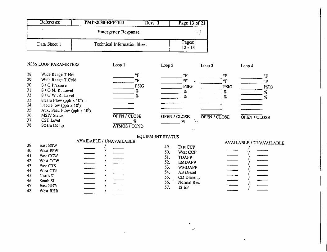
NSSS LOOP PARAMETERS
28. Wide Range T Hot29. Wide Range T Cold30. S / G Pressure31. S G N. R. Level32. S / G W .R. Level33. Steam Flow (pph x 106)34. Feed Flow (pph x 106)35. Aux. Feed Flow (pph x 103)36. MSIV Status37. CST Level38. Steam Dump
OFOFPSIG
OPEN / CLOSE
ATMOS t COND
OFOF PSIG
OPEN / CLOSEFt
OFOFPSIG
OPEN / CLOSE
OFOF
PSIG
OPEN / CLOSE
39. East ESW40. West ESW41. East CCW42. West CCW43. East CTS44. West CTS45. North SI46. Soutlh SI47. East RHR48 West RHR
AVAILABLE / lJNAVAILABLE
I _____
= ~~I
EQUIPMENT STATUS
49.50.51.52.53.54.55.56.57.
East CCPWest CCPTDAFPEMDAFPWMDAFPAB DieselCD Diesel Normal Res.12 EP
AVAILABLE / UNAVAILABLE
=____ I
= I =~~
/ _
Reference I PMP-2080-EPP-100 |-Rev. 1 I Page 13 of 21
Emergency Response
Data Sheet Technical Information Sheet I Pages:
Loop 1 Loop 2 Loop 3 Loop 4

1. Emergency Classification
Time Declared
Unusual Event
Alert
Site Area Emergency
General Emergency
2. Have notifications been completed?
a. Berrien County: yes / no / in progress
b. Michigan: yes / no / in progress
c. NRC: yes / no / in progress
d. NGG Personnel: yes I no / in progress
3. Protective Actions:
a. Local area evacuation yes / no
b. Site evacuation yes / no
c. Accountability yes / no
d. Site closed to visitors yes / no
e. Offsite protective action recommended:
. Evacuation: yes / no areas:
. Shelter: yes / no areas:'
Time:
Time:
Time:
Time:
Time:
Time:
Time:
Time:
Time:
Time:
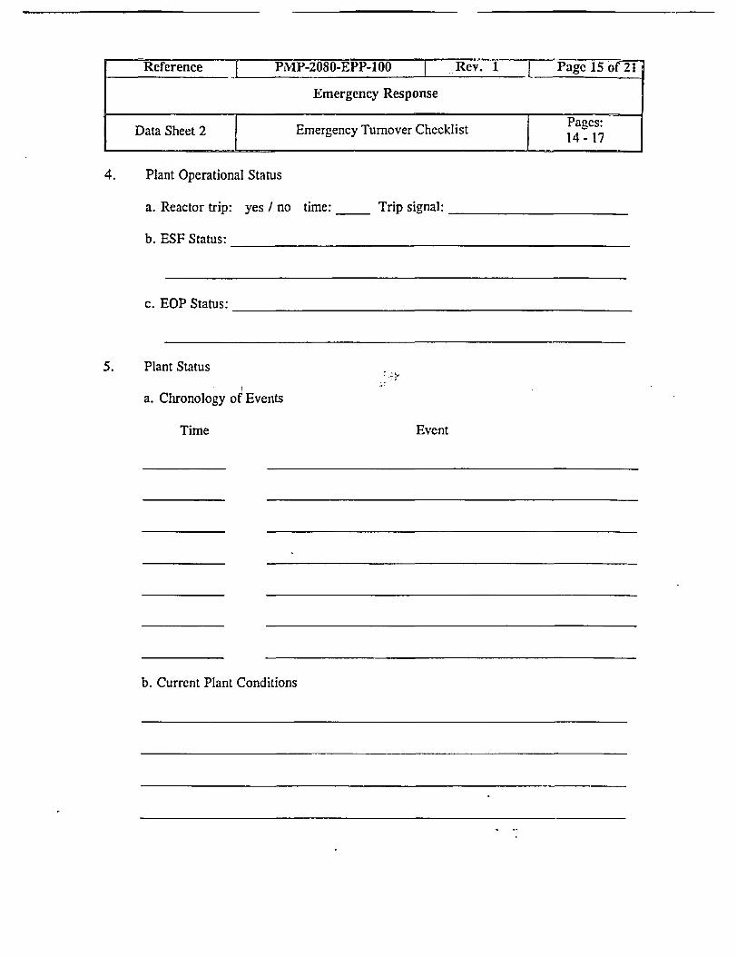
4. Plant Operational Status
a. Reactor trip: yes / no time:
b. ESF Status:
c. EOP Status:
5. Plant Status
a. Chronology of Events
Time
b. Current Plant Conditions
______ Trip signal:
Event
Referene PMIP-2080-EPP-100 I Rev. 1 L Pge 15o 21
Emergency Response
Data Sheet 2 Emergency Turnover Checklist Pages:14 - 17

c. Potential for Plant Degradation
d. Mitigating Actions Taken or Underway
6. Plant Radiological Conditions
a. Inplant/Onsite Radiological Conditions
Reference _ PMP-2080-EPP-100 r Rev. 1 I Page 16 of 21
Emergency Response
Data Sheet 2 Emergency Turnover Checklist Pages:

b. Potential for Offsite Release of Radioactivity
Airborne Water
7. Injured or Contaminated Personnel:
Name Employer
Reference-PMP-2080-EPP-100 ReV. age 17 of 21
Emergency Response
Data Sheet 2 Emergency Tumover Checklist P1 1 ~~~~~~~~~~~14 - 7
Status

3.2.3.a 3.2.3.b
y%<. Yes
3.2.4.b
Reference I PMP-2080-EPP-100 Re. age 18 of 21.
I ~ ~ ~~~-Emergency Response
1iur Procedure Flowchart Pages:Figure I 1 18 -21
Emergency delcaredPer
PMP-2080-EPP-1O1
3.2.3
No
-
II ,
No

I
Reference I PMP-2080-EPP-100 Rev. 1 Page 19 of 21
Emergency Responsc
Figure Procedure Flowchart Pages:Figure 1 I I - 21
- -

Reference I PMP-2080-EPP-100 I Rev. 1 Page 20 of 21
Emergency Response
Figure I Procedure Flowchart Pages:I 1- ~ ~~~~~~~~18 -21

3.3.3 and 3.3.4
Inform TSC of plant changesand mitigating actions planned
or completed
3.3.5
Direct announcementsas necessary or
upgradesI.
3.3.6
Reference PMP-2080-EPP Rev. ge 21 of 2T
Emergency Response
Figure_I Procedure Flowchart Pages:Figure 1 18 - 21
equest assistance rrom TSC asnecessary
.
. .
_
r
r

REVIEW AND APPROVAL TRACKING FORM
Number: PMEP-2080-EPP-101 Rev. 3b Change: 0
Title: Ernergency! Clasfcto'61fi~~~~~~~~~~~~~*
0"7" Correction (Full Procedure) El cEl Correction (Page Substitution) El cEl Cancellation El 'El Superseded (list superseding procedures):
'hange (Full Procedure) with Review of Change Only.hange (Page Substitution) with Review of Chang-e Onlylew Procedure or Change with FuIl Review
Change Driver/CDI Tracking No(s).:____________________ D N/A
Cross-Discipline Reviews: Programmatic Reviews:ElChemistry El Training, ED ALARA El Performance AssuranceElMaintenance ElWork Control ElBus. Services Proc Grp ElReactivity Mgmt TeamElNDM EElComponent Engineering ElSPS (Safety & Health)ElOperations El_____ lDesign Engineering - lSurveillance SectionElPA/PV El_____ El Emerg Oper Proc Grp ElSystem Engineering
El Reg Affairs E_____ El Environmnental E ______
El RP 0None Required El IS1/IST Coordinator 0None RequiredEl Cognizant Org Review: ____________________ Date: /
0 Technical Review: c 4"_ Date: 1(1 / 1576
E lC O pNgroc r e c e / a e
El OwneMr Concurrence: N/A Date: / /
Updated Revision Summary attached?0 Yes10 CFR 50.59 Requirements complete? Tracking No.:____________ E Yes 0N/AImplementation Plan developed? (Ref. Stp 34 18) El Ys O N/APackage Complete: _ ae i/•Qj
PORC Review Required: Yes LI No Mtg. No.:39IL?i2 CAdministrative Hold Status: El Released 6J,tesred 0N/A CR No.:______Approval Authority Review/Approval: Date: IL2i ioiExpiration Date/Ending Activity Effective Date: a/7 /0/
Periodic Review conducted? (Data Sheet 5 Complete) El Yes 0No
ICommitment Database Updated? ElYes 0 N/ANDM notified of new records or changes to records that could affect record refention? El Yes 0 N/A
/ This form is derived from the information in PMP-2010-PRC-002,Procedure Correction, Change, and Review, Rev. 9, Data Sheet 1,Review and Approval Tracking Form. Page- of _
ki'd �e a�qZM 8��'-' '5V_ 'K�
4'C�4
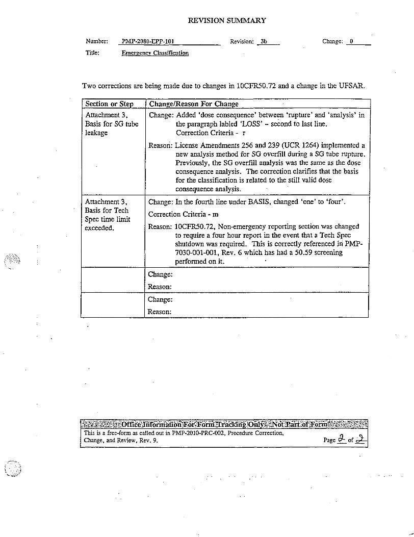
REVISION SUMMARY
Number: PMIP-2080-EPP-101
Title:
Revision: 3b Change: 0
Emer2enev Classification
Two corrections are being made due to changes in 10CFR50.72 and a change in the UFSAR.
ffi'rmayii'l, w Fa'6 m &Ting"11i a-+b'tfi riA .EThis is a free-form as called out in PMP-2010-PRC-002, Procedure Correction, cChange, and Review, Rev. 9. Page - of -
Section or Step Change/Reason For Change
Attachment 3, Change: Added 'dose consequence' between 'rupture' and 'analysis' inBasis for SG tube the paragraph labled 'LOSS' - second to last line.leakage Correction Criteria - r
Reason: License Amendments 256 and 239 (UCR 1264) implemented anew analysis method for SG overfill during a SG tube rupture.Previously, the SG overfill analysis was the same as the doseconsequence analysis. The correction clarifies that the basisfor the classification is related to the still valid doseconsequence analysis.
Attachment 3, Change: In the fourth line under BASIS, changed 'one' to 'four'.Basis for Tech Correction Criteria- mSpec time liCnoitexceeded. Reason: lOCFR50.72, Non-emergency reporting section was changed
to require a four hour report in the event that a Tech Specshutdown was required. This is correctly referenced in PMP-7030-001-001, Rev. 6 which has had a 50.59 screeningperformed on it.
Change:
Reason:
Change:
Reason:
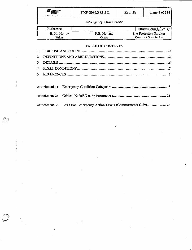
TABLE OF CONTENTS1 PlURPOSE AND SCOPE ......................................... 2
2 DEFINITIONS AND ABBREVIATIONS ......................................... 2
3 DETAILS ......................................... 6
4 FINAL CONDITIONS ......................................... 7
5 REFERENCES ......................................... 7
Attachment 1: Emergency Condition Categories .8
Attachment 2: Critical NUREG 0737 Paraeters .21
Attachment 3: Basis For Emergency Action Levels (Commitment: 6489) ................. 22
CItK PMP-2080.EPP.101 Rev. 3b Page 1 of 114
Emergency Classification
Reference EffectiveDate:,/7/1
B. K. Molloy P.E. Holland Site Protective ServicesWriter Owner Cognizant Organization

Reference PMP-2080.EPP.101 Rev. 3b l Page2 of 114
Emergency Classification
1 PURPOSE AND SCOPE
NOTE: The operator aids located in the control rooms, simulator, Technical SupportCenter and Emergency Operations Facility are updated when changes aremade to this procedure.
1.1 To ensure correct and timely classification of abnornal events into one of fouremergency classification levels if appropriate. Attachments may be used as operatoraids in a format different than the procedure provided the content remains the same.
2 DEFINITIONS AND ABBREVIATIONS
Term MeaningAlert Events are in progress or have occurred which involve an
actual or potential substantial degradation of the level ofsafety of the plant. Any releases are expected to be limited tosmall fractions of the EPA Protective Action Guidelineexposure levels.
Control Placing all local controls in position necessary for operation fromremote panels and the shift supervisor has determined that thesystems for controlling reactivity, RCS inventory, RCStemperature, and the heat sink functions have been established.
Critical Safety Subcriticality, core cooling, heat sink, pressure-temperature-Function (CSF) stress (RCS integrity), c6ntainment, and RCS inventory as
monitored in accordance with the Emergency OperatingProcedures.
Critical Safety The method by which the level of challenge to each CSF isFunction Status Tree determined in accordance with the Emergency Operating(CSFST) Procedures.Emergency Action A pre-determined, site-specific, observable threshold for aLevel (EAL) plant Initiating Condition that places the plant in a given
emergency class. An EAL can be an instrument reading; anequipment status indicator, a measurable parameter (onsite oroffsite); a discrete, observable event; results of analyses;entry into specific emergency operating procedures; oranother phenomenon which, if it occurs, indicates entry into aparticular emergency class.
Emergency A grouping of Initiation Conditions, recognizable to the SiteCondition Category Emergency Coordinator, applying to the same area of(ECC) concern and that can logically lead to escalating the

Reference I PMP-2080.EPP.101 I Rev. 3b I Page 3 of 114l
Emergency Classification
Term Meaningemergency class.
Emergency These are taken from 10 CFR 50- Appendix E. They are inClassification Level escalating order. (Notification of) Unusual Event (UE),(ECL) Alert, Site Area Emergency (SAE), and General Emergency
(GE).Explosion A rapid, violent, uncontained combustion or catastrophic failure of
pressurized equipment that potentially imparts significant energy tonearby structures or equipment.
Fission Product One of the three principal barriers to uncontrolled release ofBarrier radionuclides, i.e., fuel clad, reactor coolant system (RCS),
and the containment building (CNTMT).General Emergency Events are in progress or have occurred which involve actual(GE) or imminent substantial core degradation or melting with
potential for loss of containment integrity. Releases can bereasonably expected to exceed EPA Protective ActionGuideline exposure levels offsite for more than the immediatesite area.
Initiating Condition One of a predetermined subset of nuclear power plant(IC) conditions where either the potential exists for a radiological
emergency, or such an emergency has occurred.Loss (of a fission Severe challenge to a fission product barrier sufficient toproduct barrier) consider that barrier incapable of containing fission products.Normal Charging The normal charging flow path through the volume controlMode system including design and alternate flow paths, and flow to
reactor coolant pump seals.Potential Loss (of a Challenge to a fission product barrier sufficient to considerfission product the barrier degraded in its ability to contain fission products.barrier)Protected Area The fenced area which requires a Cook security badge for
unescorted access.Recognition A logical and convenient grouping of ECCs used to quicklyCategory eliminate non-applicable ICs from consideration during
,_________ Emergency Classification.Safe Shutdown Area Selected areas within the Protected Area that may be
occupied for the security or safe shutdown of the units.The safe shutdown areas are:* Control rooms* Central alarm station* Containment buildings in Modes 5 and 6The following are Safe Shutdown areas, if a Control Roommust be evacuated:* Diesel Generator rooms. 4KV rooms

Reference I PMP-2080.EPP.101 Rev. 3b I Page4 of 114
Emergency Classification
Term Meaning* Vicinity of all Local Shutdown Stations
Safe Shutdown Selected components deemed necessary to place and maintainEquipment a unit in Hot Shutdown with capability to establish and
maintain Cold Shutdown as described in Safe-ShutdownCapability Assessment, Proposed Modifications andEvaluations (AEPSC), Rev. 1 1986. In brief, the safeshutdown equipment can be described as:* RCS.makeup path from the Refueling Water Storage Tank
(RWST) via the Centrifugal Charging Pumps (CCPs) andBoron Injection Tank (BIT) injection lines.
- Secondary Heat Sink consisting of:
- Condensate Storage Tank (CST)- all three Auxiliary Feed Water (AFW) pumps
- Associated AFW valves- Steam Generators (SGs)- SG Main Steam Isolation Valves (MSIVs)
- SG safeties and PORVs.* Component Cooling Water (CCW) system.* Essential Service Water (ESW) system including alternate
supply to AFW.* Residual Heat Removal (RHR) system.
Diesel Generators and the emergency AC buses.CRIDs and most CRID-powered instrumentation.
* DC distribution system including batteries and batterychargers.
* All Local Shutdown Stations.* Unit crossties for BIT flow, RCP seal injection, CSTs and
AFW.Site Area Events are in progress or have occurred which involve actualEmergency (SAE) or likely major failures of plant functions needed for
protection of the public. Any releases are not expected toresult in exposure levels which exceed EPA Protective ActionGuideline exposure levels except near the site boundary.
Toxic Exposure to the worker in excess of limits specified in 29 CFR1910.1000. in practice, this should be considered forconcentrations which are capable of incapacitating the worker.
Transient A condition (1) beyond the expected steady-state fluctuationsin temperature, pressure, power level, or water level, (2)beyond the normal manipulations of the Control Roomoperating crew, and (3) that would be expected to requireactuation of fast-acting automatic control or protection systems
Reference PMP-2080.EPP.101 | Rev. 3b I Page 5 of 114
Emergency Classification
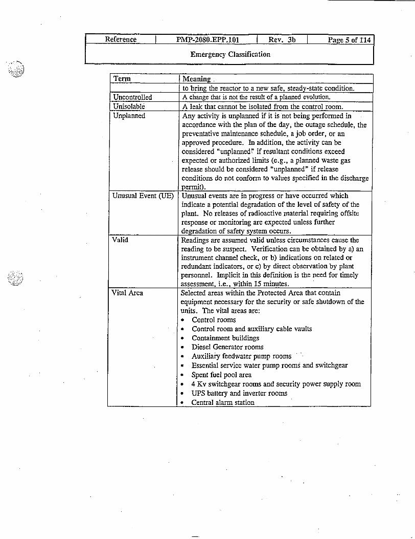
Term Meaning.to bring the reactor to a new safe, steady-state condition.
Uncontrolled A change that is not the result of a planned evolution.Unisolable A leak that cannot be isolated from the control room.Unplanned Any activity is unplanned if it is not being performed in
accordance with the plan of the day, the outage schedule, thepreventative maintenance schedule, a job order, or anapproved procedure. In addition, the activity can beconsidered "unplanned! if resultant conditions exceedexpected or authorized limits (e.g., a planned waste gasrelease should be considered "unplanned" if releaseconditions do not conform to values specified in the dischargepermit).
Unusual Event (UE) Unusual events are in progress or have occurred whichindicate a potential degradation of the level of safety of theplant. No releases of radioactive material requiring offsiteresponse or monitoring are expected unless furtherdegradation of safety system occurs.
Valid Readings are assumed valid unless circumstances cause thereading to be suspect. Verification can be obtained by a) aninstrument channel check, or b) indications on related orredundant indicators, or c) by direct observation by plantpersonnel. Implicit in this definition is the need for timelyassessment, i.e., within 15 minutes. -
Vital Area Selected areas within the Protected Area that containequipment necessary for the security or safe shutdown of theunits. The vital areas are:* Control rooms* Control room and auxiliary cable vaults* Containment buildings* Diesel Generator rooms* Auxiliary feedwater pump rooms* Essential service water pump rooms and switchgear* Spent fuel pool area* 4 Kv switchgear rooms and security power supply room* UPS battery and inverter rooms* Central alarm station

Reference PMP-2080.EPP.101 I Rev. 3b Page 6 of 114
Emergency Classification
3 DETAILS
3.1 Using Attachment 1, determine which Recognition Category applies to the abnormalconditions.
NOTE: It is likely that an event will have to be classified using more than oneRecognition Category.
3.1.1 Review ALL appropriate Initiating Conditions within the selectedRecognition Categories starting in the left-most applicable column.
3.1.2 Determine whether the threshold values for Emergency Classification havebeen exceeded.
a. Attachment 2 may be needed in making a determination of emergencyclassification under ECC S-6: Loss of Alarms or Indications.
b. The appropriate basis pages (Attachment 3) may also be used ifclarification is needed in making proper determination of emergencyclassification in any of the Recognition Categories.
3.1.3 The Initiating Conditions in Attachment 1 that are marked with an E doNOT have the entire EAL description listed in Attachment 1. In order toproperly classify an event, the basis pages in Attachment 3 must bereviewed to insure the full description of the EAL is considered whenmaking the classification. The page numbers listed in the InitiatingCondition boxes in Attachment 1 refer to the appropriate section of the basispages, Attachment 3.
3.1.4 If the threshold value has been exceeded, the higher EmergencyClassification Levels within the associated ECC must be checked to ensurethe highest ECL has been determined.
3.2 The Emergency Classification Level is the highest ECL determined in step 3.1 asappropriate - OR - any higher Emergency Classification Level as determined by SiteEmergency Coordinator (SEC) judgement as described in Attachment 1 andAttachment 3.

Reference | PMP-2080.EPP.101 I Rev. 3b Pane 7 of 114
Emergency Classification
3.3 The SEC shall evaluate plant conditions at least every 15 minutes to determine ifconditions have deteriorated to the point that the Emergency Classification Levelshould be upgraded to a higher level until the event is terminated. The need toupgrade to a higher level could be indicated by:
* Critical Safety Function Status Trees
* Additional radiation monitor alarms
* Reports from plant personnel
4 FINAL CONDITIONS
4.1 Event Classified
5 REFERENCES
5.1 Use References:
5.1.1 None
5.2 Writing References:
5.2.1 Source References:
a. NUMARC/NESP-007, Rev. 2, "Methodology for Development ofEmergency Action Levels"
b. NUMARC/NESP-007, Rev. 4, "Methodology for Development ofEmergency Action Levels'
c. Regulatory Analysis: "Revision of Regulatory Guide 1.101 to Acceptthe Guidance in NUMARC/NESP-007, Rev. 2 as an AlternativeMethodology for the Development of Emergency Action Levels'
d. NUMARC letter: "Methodology for the Development of EmergencyAction Levels," NUMARC/NESP-007, Revision 2, Questions andAnswers, June 1993 from Thomas E. Tipton, to NUMARCAdministrative Points of Contact
5.2.2 General References
a. Donald C. Cook Nuclear Plant Emergency Plan

Page9910
Emergency Condition CategoryFuel Clad Barrier Loss/Potential Loss TableRCS Barrier Loss/Potential Loss TableContainment Barrier Loss/Potential Loss Table
11 ECC H-112 ECC H-212 ECC H-312 ECC H-412 ECC H-513 ECC N-113 ECC N-213 ECC N-313 ECC N-413 ECC N-513 ECC N-613 ECC N-714 ECC R-114 ECC R-214 ECC R-315 ECC S-115 ECC S-215 ECC S-315 ECC S-516 ECC S-716 ECC S-816 ECC S-916 ECC S-1017 ECC H-2 - H-518 ECC N-1 - N-719 ECC R-1- R-320 ECC C-320 ECC C-420 ECC C-520 ECC C-620 ECC C-7
SEC JudgementSecurity EventsControl Room EvacuationFireToxic or Flammable GasesSeismic ActivityTornado/High WindVisible Structural DamageVehicle CollisionMain Turbine Rotating Component FailurePlant FloodingUnanticipated ExplosionRadioactive Effluent ReleaseIncreasing In-Plant Radiation LevelLoss of Water Level in Any Area Holding Irradiated FuelFailure of Reactor Protection SystemLoss of AC Power (Modes 1-4)Loss of DC Power (Modes 1-4)Loss of Systems Needed to Achieve/Maintain Hot ShutdownFuel Clad DegradationExcessive RCS LeakageTech Spec ComplianceLoss of Communication Systems (Modes 1-4)Hazards and Other Conditions (Modes 5, 6)Natural/Destructive Phenomena (Modes 5, 6)Abnormal Radiation Levels/Effluents (Modes 5, 6)Cold Shutdown/Refueling/Defueled - Loss of AC Power (Modes 5, 6)Cold Shutdown/Refueling - Inability to Maintain Cold ShutdownCold Shutdown/Refueling - Fuel Clad Degradation (Modes 5, 6)Cold Shutdown/Refueling - Loss of Communications (Modes 5, 6)Cold Shutdown/Refueling - Loss of DC Power (Modes 5, 6)
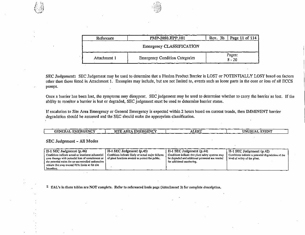
SEC Judgement: SEC Judgement may be used to determine that a Fission Product Barrier is LOST or POTENTIALLY LOST based on factorsother than those listed in Attachment 1. Examples may include, but are not limited to, events such as loose parts in the core or loss of all ECCSpumps.
Once a barrier has been lost, the symptoms may disappear. SEC judgement may be used to determine whether to carry the barrier as lost. If theability to monitor a barrier is lost or degraded, SEC judgement must be used to determine barrier status.
If escalation to Site Area Emergency or General Emergency is expected within 2 hours based on current trends, then IMMINENT barrierdegradation should be assumed and the SEC should make the appropriate classification.
GENERAL EMERGENCY SITE AREA EMERGENCY ALERT UNUSUAL EVENT
SEC Judgenent - All Modes
11-1 SEC Judgenent (p.46) H-1 SEC Judgement (p.45) 11-1 SEC Judgement (p.44). H-1 SEC Judgement (p.42)Conditions indicate actual or imminent substantial Conditions indicate likely or actual major failures Conditions indicate that plant safety systems may Conditions indicate a potential degradation of thecore danage with potential loss of containment or of plant functions needed to protect the public. be degraded and additional personnel are needed level of safety of the plant.the potential exists for an uncontrolled radioactive for additional monitoring.release that may exceed EPA limits at the siteboundary.
£ EAL's in tese tables are NOT complete. Refer to referenced basis page (Attachment 3) for complete description.
Reference I PMP-2080.EPP.101 | Rev. 3b Pa e 11 of 114
Emergency CLASSIFICATION
Attachment Emergency Condition Categories 8 - 20
'p - >*!
'*,- J :
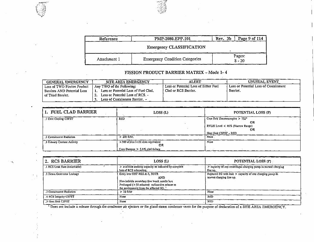
FISSION PRODUCT BARRIER MATRIX - Mode 1- 4
GENERAL EMERGENCY SITE AREA EMERGENCY ALERT UNUSUAL EVENTLoss of TWO Fission Product Any TWO of the Followiig: Loss or Potential Loss of Either Fuel Loss or Potential Loss of ContainmentBarriers AND Potential Loss 1. Loss or Potential Loss of Fuel Clad. Clad or RCS Barrier. Barrier.of Third Barrier. 2. Loss or Potential Loss of RCS. -
3. Loss of Containment Barrier. -
1. FUEL CLAD BARRIER LOSS (L) POTENTIAL LOSS (P)
.1 Core Cooling CSFST RED Core Exit Thermocouples > 752-OR
RVLIS Level < 46% (Narrow Range)OR
Heat Sink CSFST - RED.2 Containment Radiation > 200 Rlhr. None
.3 Primary Coolant Activity >300 uCi/cc 1-131 dose equivalent NoneOR
Core Damage > 5.0% clad failure
2. RCS BARRIER LOSS (L) POTENTIALLOSS P)
.1 RCS Leak Rate (unisolable) / > available makeup capacity as indicated by complete > capacity of one centrifugal charging pump in normal chargingloss of RCS subcooling. line up.
.2 Steam Generator Leakage Entry into OIIP 4023.E-3, SGTR Ruptured SG with leak > capacity of one charging pump inAND normal charging line up.
Non-isolable secondary line break results in aProlonged (>30 minutes) radioactive release tothe environment from the affected SG.
.3 Containient Radiation > 10 Rlhr None
.4 RCS Integrity CSPST None RED
.5 lIeat Sink CSFST None RED
Does not include a release through the condenser sir ejectors or the gland steam condenser vents for the purpose of declaration of a SITE AREA EMERGENCY.

1.3
FISSION PRODUCT BARRIER MATRIX - Mode 1-4GENE RAL EIERGENCY SITE AREA EMERGENCY rALERT I UNUSUAL E ENT
Loss of TWO Fission Product Any TWO of the Following: Loss or Potential Loss of Either Fuel Loss or Potential Loss of ContainmentBarriers AND Potential Loss 1. Loss or Potential Loss of Fuel Clad. Clad or RCS Barrier. Barrier.of Third Barrier. 2. Loss or Potential Loss of RCS.
13. Loss of Containrent Barrier.
3. CONTAINMENT BARRIER LOSS (L) POTENTIAL LOSS (P).1 Containment Radiation None > 1000 R/hr.
OR._________________________________________________________ _ .Core dam age > 20% clad failure.
.2 Containment Integrity Unisolable breach of containment. NoneOR
Rapid unexplained containment pressure or sump level drop followingpressure rise caused by a LOCA.
ORContainment pressure/sump level NOT performing as expected forconditions.
OREntry into ECA-1.2! LOCA Outside Containment.
.3 S Secondary Side Release la. Primary to secondary leak rate > Tech. Spec. limit. (p35) NoneAND
b. Secondary line break OUTSIDE Containment results In release(>30 min.) to the environment.
OR2. Release of secondary coolant from the affected SC to the -
environment with ilert alarm on any SG PORV rad monitor.' E.4 Containment CSFST None RED.5 Contaitiment lydrogen None >4.0%
ORContainment lydrogen >0.5% AND any lydrogen Control equipmentinoperable..6 Containmenit Pressure Control Noneioerbe.6 Contanmeiit Pessure Cntrol Noe BOTH CTS trains OR 130Tl containent air recirc fans inoperable OR failto auto start on teir containment pressuire setpolnt OR containment pressure
.7 Core Exit Termocouples None Core Cooling CSFST - RED
_oe s n ot i n l d e a r l e s t r u h h c n e s e ir e e t o s o t e g l n te m c o d n e r v n t o t e R e sto ra to n p ro c e d ur s n o t e ffe c tiv e w ith in 15 m in u te s.Does not include a release through the condenser air ejectors or the gland steam condenser vents for the prpose of declaration of a SITE AREA EMERGENCY.~
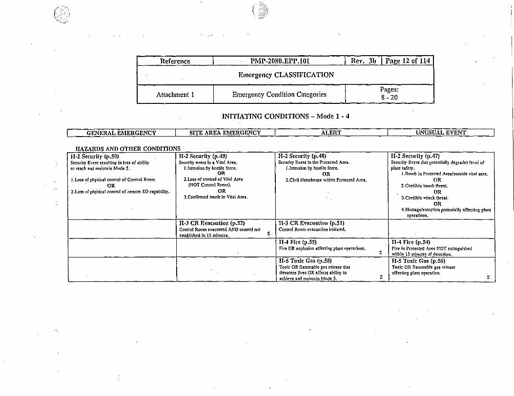
INITIATING CONDITIONS - Mode 1- 4
GENERAL EMERGENCY SITE AREA EMERGENCY ALERT UNUSUAL EVENT
IIAZARDS AND OTIIER CONDITIONS11-2 Security (p.50) H-2 Security (p.4 9) 11-2 Security (p.4 8) II-2 Security (p.47 )Security Event resulting in loss of ability Security event in a Vital Atea. Security Event in the Protected Area. Security Event that potentially degrades level ofto reach and maintain Mode 5. I.lntrusion by hostile force. I.Intrusion by hostile force. plant safety.
OR OR I.Bomb in Protected Area/outside vital area.I .Loss of physical control of Control Room 2.Loss of control of Vital Area 2.Civil disturbance within Protected Area. OR
OR (NOT Control Room), 2.Credible bomb threat.2.Loss of physical control of remote SD capability. OR OR
3.Confirmed bomb in Vital Area. 3.Credible attack threat.OR
4.1Hostage/extortion potentially affecting plantoperations.
11-3 CR Evacuation (p.52) 11-3 CRL Evacuation (p.51)Control Room evacuated AND control not Control Room evacuation initiated,established in 15 minutes. S
11-4 Fire (p.55) H-4 Fire (p.54)Fire OR explosion affecting plant operations. Fire in Protected Area NOT extinguished
. within 15 minutes of detection.11-5 Toxic Gas (p.58) 11-5 Toxic Gas (p.56)Toxic OR flammable gas release that Toxic OR flammable gas releasethreatens lives OR affects ability to affecting plant operation.achieve and maintain Mode 5. E
Reference _ IMP-2080.EPP.101 Rev. 3b Page 12 of 114
Emergency CLASSIFICATION
Attachment 1 Emergency Condition Categories Pages:

--
INITIATING CONDITIONS - Mode 1- 4
GENERAL EMERGENCY I SITE AREA EMERGENCY ALERT |UNUSUAL EVENT l
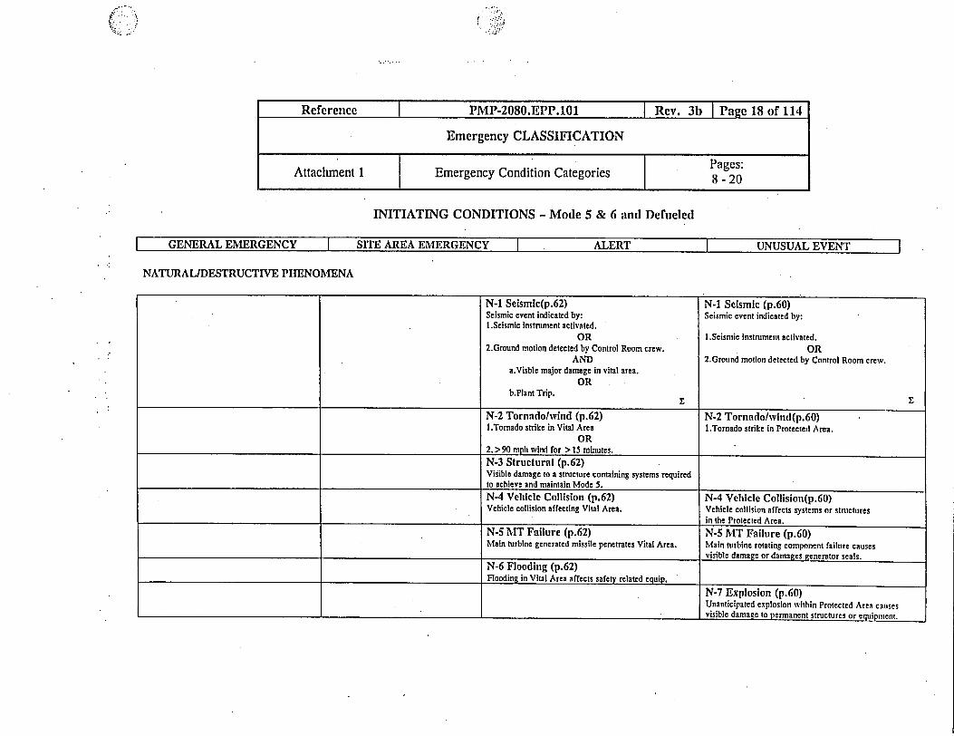
NATURAL/DESTRUCTIVE PIENOMENA
N-1 Seismic (p. 62) N-1 Seismic (p.60)Seismic event Indicated by: Seismic event indicated by:
I .Scismic instrument activated I.Seismic instrument activated
OR OR2.Ground motion detected by Control Room crew 2.Ground motion detected by Control Room crew.
ANDI.Visble major damage in vital area.
OR2.Plant Trip. E
N-2 Tornadolwind (p.62) N-2 Tornado/vind (p.6 0)I.Tornado strike in Vital Area I.Tornado strike within Protected Area.
OR2. > 90 mph wind for > 15 minutes.
N-3 Structural (p.62)Visible damage to a structure containing systemsrequired to achieve and maintain Mode 5.
N-4 Vehicle Collision (p.62) N-4 Vehicle Collision (p.60)Vehicle collision affecting Vital Area. Vehicle collision affecting systems or structures
within the Protected Area.
N-5 MT Failure (p.62) N-5 MT Faillre(p.60)Main turbine generated missie penetrates Vital Area. Main turbine rotating component failure causes
__ __ __ __ _ __ __ __ _ __ __ __ __ _ _ ____ visible damage or damages generator seals.
N-6 Flooding (p.62)Flooding in Vital Area affects safety related equipment.
N-7 Explosloii (p.60)Unanticipated explosion within Protected Areacauses visible damage to permanent structures or
I_equipment.
Reference PMP-2080.EPP.101 b Page 13 of 114
Emergency CLASSIFICATION
Attachment 1 Emergency Condition Categories 8 -20

INITIATING CONDITIONS - Mode 1- 4
GENERAL EMERGENCY SITE AREA EMERGENCY ALERT UNUSUAL EVENT
ABNORMAL RADIATION LEVELSIEFFLUENTS
R-1 Effluent release (p.71) R-1 Efrluent release (p.69) R-1 Effluenit release (p.67) R-1 Effuent release (p.65)Site boundary dose > I REM TEDE or 5 REM CDE Site boumdary dose > 100 mrem TEDE Unplanned Rad release >200X ODCM limits Unplanned Rad release >2X ODCM limits forto thyroid based on: or 500 mrem CDE to thyroid based on: for > 15 min. based on: > 60 minutes based on:I.Survey results I.Survey results
OR OR 1.200X rad nionitor high alarm setpoint. 1.2X rad monitor high aann setpoint.2.Dose assessment 2.Dose assessment OR OR
OR OR 2.Gas or liquid sample results. 2.Gas or liquid sample results.3.Emuent monitor readings > 15 minutes 3.Effluent monitor readings > 15 minutes.
R-2 Plant Rad level (p.74) R-2 Plant Rad level(p.73)Rad levels that Impede plant operations based Unexpected reading on Area Monitor IOOOXon: the 24 hr average.
1. > 15 mR/hr in Control Rm(s) /CASOR
2. > 100 mR/hr at remote S/D areas.
R-3 Loss of level (p.78) R-3 Loss of level (p.76)Major damage to rradiated fuel or loss of Uncontrolled lowering in refueling cavity, SPlevel that has or will uncover fuel outside of or Transfer Canal indicated by:the reactor vessel based on:I.Visual observation of levels. I.lnability to maintain > 643'4" In SFP or Transfer Canal
OR with irradiated fuel present2.Rad monitor alarms OR
OR 2.1nability to maintain > 643'4' in the rfueling cavity3.Level < 632'4' SFP or Transfer Canal. with irradiated fuel in containment.
Reference I PMP-2080.EPP.101 Rev. 3b Page 14 of 114
Emergency CLASSIFICATION
Pages:Attachment 1 1 Emergency Condition Categories S - 20

INITIATING CONDITIONS - Mode 1-4
I GENERAL EMERGENCY I SITE AREA EMERGENCY I ALERT | UNUSUALEVENT l
SYSTEM MALFUNCTIONS
Reference I PMP-2080.EPP.101 I Rev. 3b Page 15 of 114
Emergency CLASSIFICATION
Attachment 1 Emergency Condition Categories Pages:
S-I RPS failure (p.83) S-I RPS failure (p.82) S-l RPS failure (p.80)I .Auto and manual Reactor Trip fails from Control Auto and manual Reactor Trip fails from Auto Reactor Trip fails AND manual tripRm AND Suberiticality and Core Cooling CSFSTs Control room. successful from Control Room.are RED
OR2.Subcriticality and Ileat Sink CSr'STs are RED.
S-2 Loss or AC (p.88) S-2 Loss of AC (p.87) S-2 Loss of AC (p.86) S-2 Loss of AC (p.85)I.Prolonged loss of all AC (A and D -T buses) Loss of all AC (A and D - T buses) for AC power supply to T buses reduced to a Loss of ALL OFF-SITE power (Auxiliary, Reserve andAND Core Cooling CSFST - ORANGE. > 15 minutes. single source for > 15 minutes. 69kv Transformers) to the T Buses for > 15 minutes.
OR2.Loss of all AC (A and D - T buses) expected to last
for > 4 irs.
S-3 Loss of DC power (p.90)Loss of ALL vital DC buses AD AND CD for> 15 minutes (bus volts < 220v)
S-5 Loss of Ilot SD sys (p.91)Loss of ability to achieve or maintain hotshutdown based on entiy into:
I.OIIP 4023.FR-H. 1, Response to Loss ofSecondary leat Sink
OR2.011P 4023.FR-C.1, Response to InadequateCore Cooling.

(7
INITIATING CONDITIONS - Mode 1-4
GENERAL EMERGENCY SITE AREA EMERGENCY 'ALERT UNUSUAL EVENT
SYSTEM MALFUNCTIONS
S-6 Loss of Alarms (p.97) S-6 Loss or Alarms (p.94) S-6 Loss or Alarms (p.92)Loss of ability to monitor alarms during a Unplanned loss of most or all Safety System ILUnplanned loss of Safety System annunciators ortransient indicated by: annunciators or Attachment 2 indicators for indicators or Attachment 2 parameters for > 15I.Loss of Safety System annunciator panel(s) for > 15 minutes with transient in progress or minutes.> 15 minutes. compensatory tndicators unavailable and AND
AND additional monitoring is required. 2.Additional monitoring required.2.Loss of Attachment 2 Critical ANDParameters for > 15 minutes. 3.Compensatory indications for lost annunciators are
AND available.3.Compensatory indications notavailable (PPC. SPDS). Z
S-7 Degrade(d Clad (p.99)l.RCS activity > 1.0 uCI/gram 1-131 dose equivalent
for > 48 hrs.OR
2.RCS activity > 100/1 uCi/gram.S-8 RCS Leakage (p.100)RCS leakage exceeds 10 gpm pressure boundaryleakage, SG tube leakage or unidentified leakageOR > 25 gpm dentified leakage.S-9 Tecli Spec (p. 101)Unit not in required mode within LCO time linits.S-10 Loss of Conini. (p.102)Unplanned loss of all on or off-site communications
Reference I PMP-2080.EPP.101 Rev. 3b Page 16 of 114
Emergency CLASSIFICATION
Attachment 1 | Emergency Condition Categories Pages:

! --: *;.
..-
INTIATING CONDITIONS - Mode 5 & 6 and Defueled
GENEIAL EMERGENCY I SITE AREA EMERGENCY ALERT UNUSUAL EVENT
IIAZARDS AND OTIIER CONDITIONS
11-2 Security (p.50) 11-2 Security (p.49) H-2 Security (p.48) II-2 Security (p.4 7)Security Event resulting in loss of Security event in a Vital Area. Security Event in the Protected Area. Security Event that potentially degradesability to reach/ maintain Mode 5. 1. Intrusion by hostile force. 1. Intrusion by hostile force. level of plant safety,
OR OR 1. Bomb in Protected Area.1. Loss of physical control of Control Room 2. Loss of control of Vital Area 2. Civil disturbance within Protected Area. OR
OR (NOT Control Room). 2. Credible bomb threat.2. Loss of physical control of remote SD OR OR
capability. 3. Confirmed bomb in Vital Area. 3. Credible attack threat.
OR4. Hostage/extortion potentially
affecting plant uperations.11-3 CR Evacuation (p.52) H-3 CR Evacuation (p.51)Control Room evacuated AND control not Control Room evacuation initiated.established within 15 minutes.
E
11-4 Fire (p.55) 11-4 Fire (p.54)Fire OR explosion affecting plant operations. Fire in Protected Area NOT extinguished within
. 15 minutes.
H-5 Toxic Gas (p.58) 11-5 Toxic Gas (p.56)Toxic OR flammable gas release that Toxic OR flammable gas release affectingthreatens lives OR affects ability to achieve plant operation.and maintain Mode 5.
I:-
* Rcference I PMP-2080.EPP.101 I Rev. 3b Page 17 of 114
Emergency CLASSIFICATION
Attachment 1 Emergency Condition Categories 8 - 20
INITIATING CONDITIONS - Mode 5 & 6 and Defueled
I GENERAL EMERGENCY I SITE AREA EMERGENCY I ALERT | UNUSUAL EVENT =
NATURAL/DESTRUCTIVE PHENOMENA
Reference IPMP-2080.EPP.1l Rev. 3b Page 18 of 114
Emergency CLASSIFICATION
Pages:Attachment 1 1 Emergency Condition Categories 8 - 20
N-1 Seismlc(p.62) N-1 Selsmic (p.60)Seismic event indicated by: Seismic event indicated by:I.Seismic instrument activated.
OR I.Seismic Instrument activated.2.Ground motion detected by Control Room crew. OR
AND 2.Ground motion detected by Control Room crew.a.Visble major damage in vital area.
ORb.Plant Trip.
N-2 Tornado/wind (p.62) N-2 Tornado/wind(p.60)I.Tornado strike in Vital Area I.Tornado strike in Protected Area.
OR2. > 90 mph wind for > 15 minutes.
N-3 Structtiral (p.62)Visible damage to a structure containing systems requiredto achieve and maintain Mode 5.
N-4 Vehicle Collision (p.62) N-4 Vehicle Collision(p.60)Vehicle collision affecting Vital Atea. Vehicle collision affects systems or structures
.__________________________________________ in the Protected Area.
N-S IT Failure (p.62) N-5 MT Failure (p.60)Main turbine generated missile penetrates Vital Area. Main turbine rotating component failure causes
visible damage or damages generator seals.
N-6 Flooding (p.62)Flooding in Vital Area affects safety related equip.
N-7 Explosion (p.60)Unanticipated explosion within Protected Area catisesvisible damage to permanent structures or equipmeit.
INITIATING CONDITIONS - Mode 5 & 6 and Defueled
GENERAL EMERGENCY SITE AREA EMERGENCY ALERT UNUSUAL EVENT
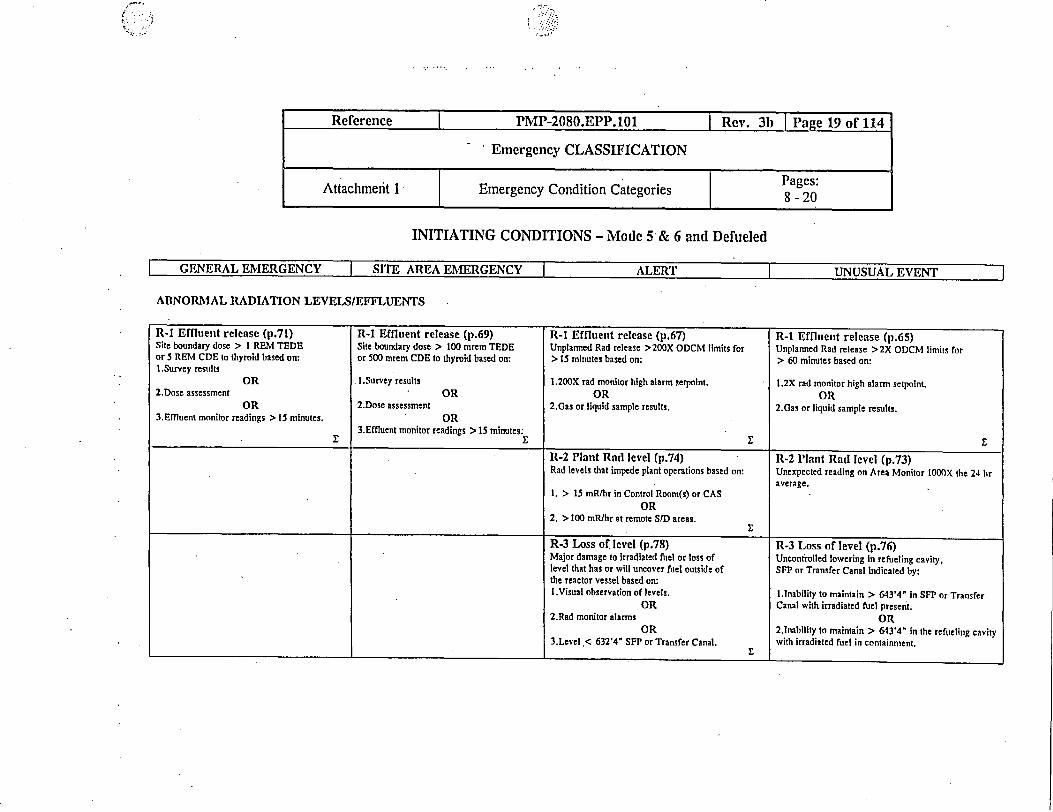
ABNORMAL RADIATION LEVELS/EFFLUENTS
R-1 Erfitent release (p.71) R-1 Effluent release (p.69) R-1 Effluent release (p.67) R-1 Eriluent release (p.6 5)Site boundary dose > I REM TEDE Site boundary dose > 100 mrem TEDE Unplanned Rad release >200X ODCM limits for Unplanned Rad release >2X ODCM limits foror 5 REM CDE to thyroid based on: or 500 mnrem CDE to thyroid based on: > 5 minutes based on: > 60 minutes based on:I.Survey results
OR I.Survey results 1.200X rad monitor high alarm setpoint. 1.2X rad monitor high alarm setpoint.2.Dose assessment OR OR OR
OR 2.Dose assessment 2.Gas or liquid sample results. 2.Gas or liquid sample results.3.Effluent monitor readings > 15 minutes. OR
3.Effluent monitor readings > 15 minutes. £
R-2 Plant Rad level (p.74) R-2 Plant Rad level (p.73)Rad levels that impede plant operations based on: Unexpected reading on Area Monitor IOOOX the 24 hr
average.1. > 15 mRthr in Control Room(s) or CAS
OR2. > 100 nfhr at remote S/D areas.
R-3 Loss of level (p.78) R-3 Loss of level (p.76)Major damage to irradiated fuel or loss of Uncontrolled lowering in refueling cavity,level that has or will uncover fuel outside of SFP or Transfer Canal Indicated by:the reactor vessel based on:I.Visual observation of levels. lInability to maintain > 643'4" In SFP or Transfer
OR Canal with irradiated fuel present,2.Rad monitor alarms OR
OR 2,lnability to maintain > 643'4' in the refueling cavity3.Level < 63i-4' SFP or Transfer Canal. with irradiated fuel in containment.
Reference I PMP-2080.EPP.101 I Rev. 3b Page 19 of 114
Emergency CLASSIFICATION
Attachment 1 | Emergency Condition Categories Pages:
t�- .W .
/.
INITIATING CONDITIONS - Mode 5 & 6 and Defueled
GENERAL EMERGENCY I SITE AREA EMERGENCY ALERT UNUSUAL EVENT
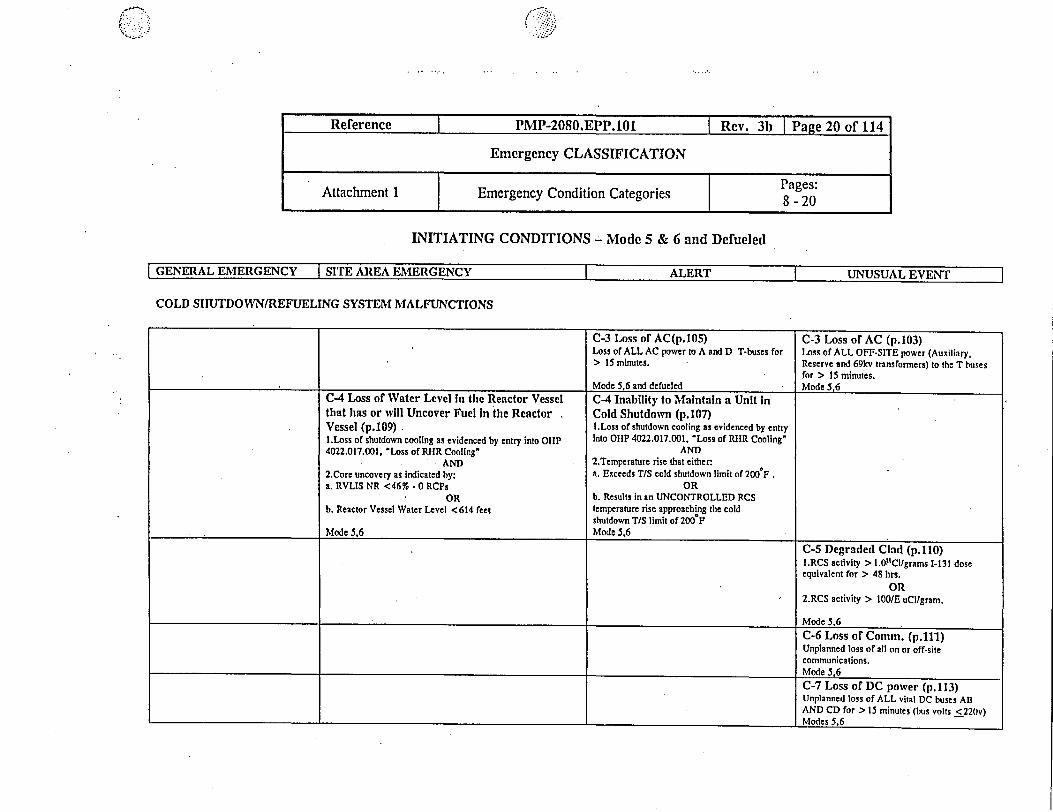
COLD SIIUTDOWN/REFUELING SYSTEM MALFUNCTIONS
C-3 Loss or AC(p.105) C-3 Loss of AC (p.103)Loss of ALL AC power to A and D T-buses for Loss of ALL OFF-SITE power (Auxiliary,> 15 minutes. Reserve and 69kv transformers) to the T buses
for > 15 minutes.Mode 5,6 and defueled - Mode 5,6
C-4 Loss of Water Level n the Reactor Vessel C-4 Inability to Maintain a Unit inthat has or will Uncover Fuel in the Reactor . Cold Shutdown (p.107)Vessel (p.109) I.Loss of shutdown cooling as evidenced by entryI.Loss of shutdown cooling as evidenced by entry into OIIP Into OIIP 4022.017.001. Loss of RIIR Cooling'4022.017.001, 'Loss of RHR Cooling' AND
AND 2.Temperature rise that either:2.Core uncovery as indicated by: a. Exceeds TIS cold shutdown limit of 200 F.a. RVLIS NR <46% - 0 RCPs OR
OR b. Results in an UNCONTROLLED RCSb. Reactor Vessel Water Level <614 feet temperature rise approaching the cold
shutdown T/S limit of 200'FMode 5,6 Mode 5,6
C-5 Degraded Clad (p.110)I.RCS activity > 1.0"lCi/grams 1-131 doseequivalent for > 48 hrs.
OR. 2.RCS activity > 00/E uCllgram.
Mode 5,6
C-6 Loss of Comm. (p.111)Unplanned loss of all on or off-sitecommunications.Mode 5,6C-7 Loss of DC power (p.113)Unplanned loss of ALL vital DC buses ABAND CD for > 15 minutes (bus volts <220v)Modes 5,6
F-. ..
Reference | PMP-2080.EPP.101 I Rev. 3 Page 20 of 114
'Emergency CLASSIFICATION
Pages:Attachment 1 1 Emergency Condition Categories 18 - 20

Reference PMP-2080.EPP.101 Rev. 3b Page 21 of 114
Emergency CLASSIFICATION
Attachment 2 Critical NUREG 0737 Parameters Page:21
PARAMETERS INSTRUMENTATIONNeutron Flux - (Gammametrics) NRI-21, 23Reactor Coolant Pressure (Wide Range) NPS-121, 122Reactor Coolant Outlet Temperature THOT (Wide Range) NTR-110, 130Reactor Coolant Outlet Temperature TCOLD (Wide Range) NTR-210, 230Incore Thermocouples (Core Exit Thermocouples) T/S 1-65Reactor Coolant System Subcooling Margin Monitor SUBCOOL MARReactor Coolant Inventory System (Reactor Vessel Level'Indication) NLI-110, 111, 120, 121, 130, 131Pressurizer Water Level NLP-151, 152, 153Charging Pump Flow IFI-51, 52, 53, 54Charging Pump Breaker Status lE, 1W, 2E, 2W Control Room Position Indicating Lights for BreakersSafety Injection Pump Breaker Status 1N, 1S, 2N, 2S Control Room Position Indication Lights for BreakersSafety Injection Flow IFI-260 - 266Refueling Water Storage Tank Water Level ILS-950, 951Containment Water Level NLA-320, NLT-321Containment Pressure (Wide Range) PPA-310, 312Containment Pressure (Narrow Range) PPP-300, 301, 302, 303Containment Hydrogen Monitoring ESR-1 thru 9Containment Isolation Valve Position Monitoring Control Room Position Indicating LigltsContainment Area Radiation Monitor (High Range) Unit 1 VRA-1310, 1410, Unit 2-2310, 2410Steam Line Pressure MPP-210, 211, 212, 220, 221, 222, 230, 231, 232, 240, 241, 242Steam Generator Water Level (Wide Range) BLI-110, 120, 130, 140Steam Generator Water Level (Narrow Range) BLP-110, 111, 112, 120, 121, 122, 130, 131, 132, 140, 141, 142Auxiliary Feedwater Flow Rate FFI-210, 220, 230, 240Condensate Storage Tank Level. CLI-113, 114, CLR-110, 111
fe-

FISSION PRODUCT BARRIER NAME, LOSS/POTENTIAL LOSS, & DESCRIPTION
FUEL CLAD BARRIER 1.1: CRITICAL SAFETY FUNCTION STATUS TREES
MODE APPLICABILITY
Modes 1, 2, 3, 4
EAL THRESHOLD VALUE
LOSS:
Core Cooling Critical Safety Function Status Tree - RED
POTENTIAL LOSS:
Core Exit Thermocouples > 752°
-OR-
RVLIS level < 46% (Narrow Range)
-OR-
Heat Sink Critical Safety Function Status Tree - RED.
BASIS (References)
LOSS - The core cooling critical safety function RED path indicates significant superheating and coreuncovery and is considered to indicate a loss of the fuel clad barrier. One of the indicators of the corecooling critical safety function red is when the core exit thermocouple temperature is equal to or greaterthan 1200 degrees Fahrenheit.
POTENTIAL LOSS - Core exit thermocouple temperature equal to or greater than 752 degreesFahrenheit or RVLIS level < 46 % (Narrow Range) corresponds to a loss of subcooling and is indicativeof a potential loss of the fuel clad barrier. The Heat Sink Critical Safety Function - RED path indicatesthat the heat sink is under extreme challenge and is indicative of a potential loss of the fuel clad barrier.
DEVIATION FROM NUMARC:
Reference I PMP-2080.EPP.101 I Rev. 3b IPae 22 of 114
Emergency CLASSIFICATION
-- Iacunen 3 1 Basis For Emergency Action Levels Pages:Attachment 3 (Commitment: 6489) 1 22 - 114
None
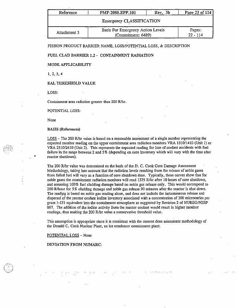
FISSION PRODUCT BARRIER NAME, LOSS/POTENTIAL LOSS, & DESCRIPTION
FUEL CLAD BARRIER 1.2 - CONTAINMENT RADIATION
MODE APPLICABILITY
1,2,3,4
EAL THRESHOLD VALUE
LOSS:
Containment area radiation greater than 200 Rlhr.
POTENTIAL LOSS:
None
BASIS (References)
LOSS - The 200 Rlhr value is based on a reasonable assessment of a single number representing theexpected monitor reading on the upper contaimnent area radiation monitors VRA 1310/1410 (Unit 1) orVRA 2310/2410 (Unit 2). This represents the expected reading for loss of coolant accidents with fuelfailure in the range between 2 and 5 % (depending on core inventory which will vary with the time afterreactor shutdown).
The 200 R/hr value was determined on the basis of the D. C. Cook Core Damage AssessmentMethodology, taking into account that the radiation levels resulting from the release of noble gasesfrom failed fuel will vary as a function of core shutdown time. Typically, these curves show that fornoble gases the contaimnent radiation monitors will read 1325 Rlhr after 10 hours of core shutdown,and assuming 100% fuel cladding damage based on noble gas release only. This would correspond to200 R/hour for 5 % cladding damage and noble gas release 90 minutes after the reactor is shut down.The reading is based on noble gas reading alone, and does not include the instantaneous release anddispersal of the reactor coolant iodine inventory associated with a concentration of 300 microcuries pergram 1-131 equivalent into the containment atmosphere as suggested by Revision 2 of NUREG/NESP007. The addition of the iodine activity from the reactor coolant would result in higher monitorreadings, thus making the 200 R/hr value a conservative threshold value.
This assumption is appropriate since it is consistent with the current dose assessment methodology ofthe Donald C. Cook Nuclear Plant, an ice condenser containment plant.
POTENTIAL LOSS - None
DEVIATION FROM NUMARC:
Reference I PMP-2080.EPP.101 I Rev. 3b I Page 23 of 114
Emergency CLASSIFICATION
Attachment 3 Basis For Emergency Action Levels Pages:ent 3 !-1 (Commitment: 6489) 22 - 114

Reference I PMP-2080.EPP.101 I Rev. 3b IPae 24 of 114
Emergency CLASSIFICATION
Attachment 3 Basis For Emergency Action Levels Pages:(Commitment: 6489) 1 22 -114
Calculation of radiation monitor reading is based on dispersal of noble gases only (iodine inventory notincluded) from the reactor coolant.
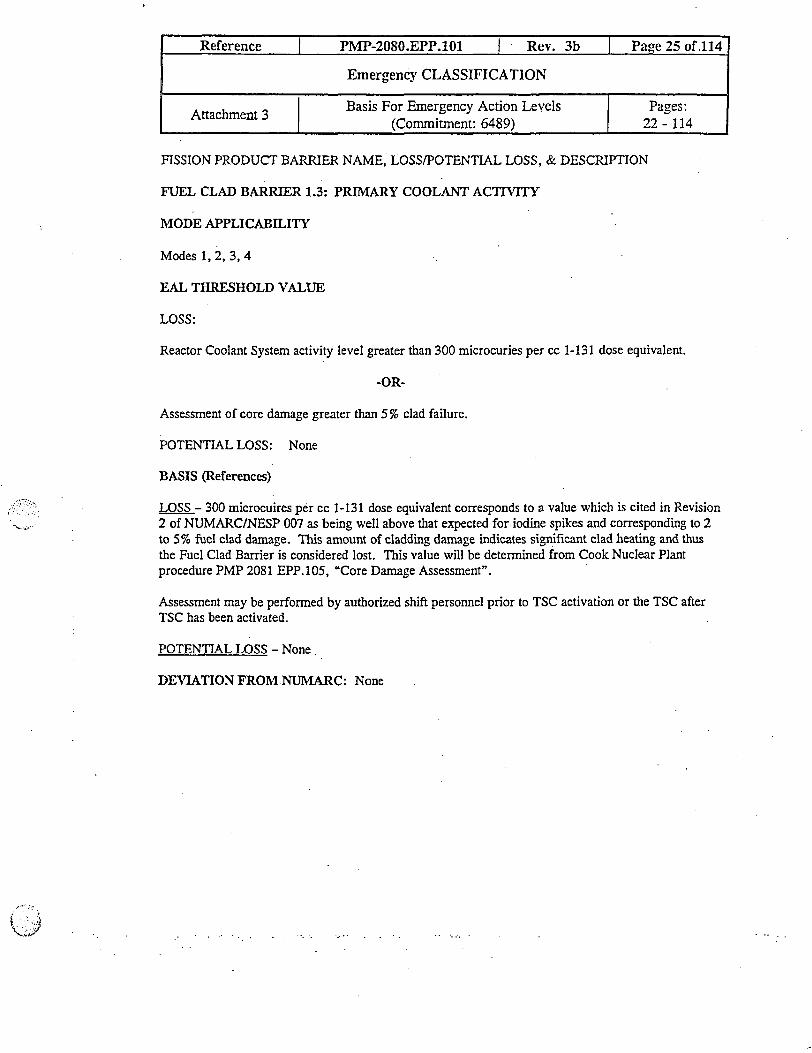
FISSION PRODUCT BARRIER NAME, LOSS/POTENTIAL LOSS, & DESCRIPTION
FUEL CLAD BARRIER 1.3: PRIMARY COOLANT ACTIVITY
MODE APPLICABILITY
Modes 1, 2, 3, 4
EAL THRESHOLD VALUE
LOSS:
Reactor Coolant System activity level greater than 300 microcuries per cc 1-131 dose equivalent.
-OR-
Assessment of core damage greater than 5 % clad failure.
POTENTIAL LOSS: None
BASIS (References)
LOSS - 300 microcuires per cc 1-131 dose equivalent corresponds to a value which is cited in Revision2 of NUMARC/NESP 007 as being well above that expected for iodine spikes and corresponding to 2to 5% fuel clad damage. This amount of cladding damage indicates significant clad heating and thusthe Fuel Clad Barrier is considered lost. This value will be determined from Cook Nuclear Plantprocedure PMP 2081 EPP. 105, "Core Damage Assessment".
Assessment may be performed by authorized shift personnel prior to TSC activation or the TSC afterTSC has been activated.
POTENTIAL LOSS - None.
DEVIATION FROM NUMARC: None
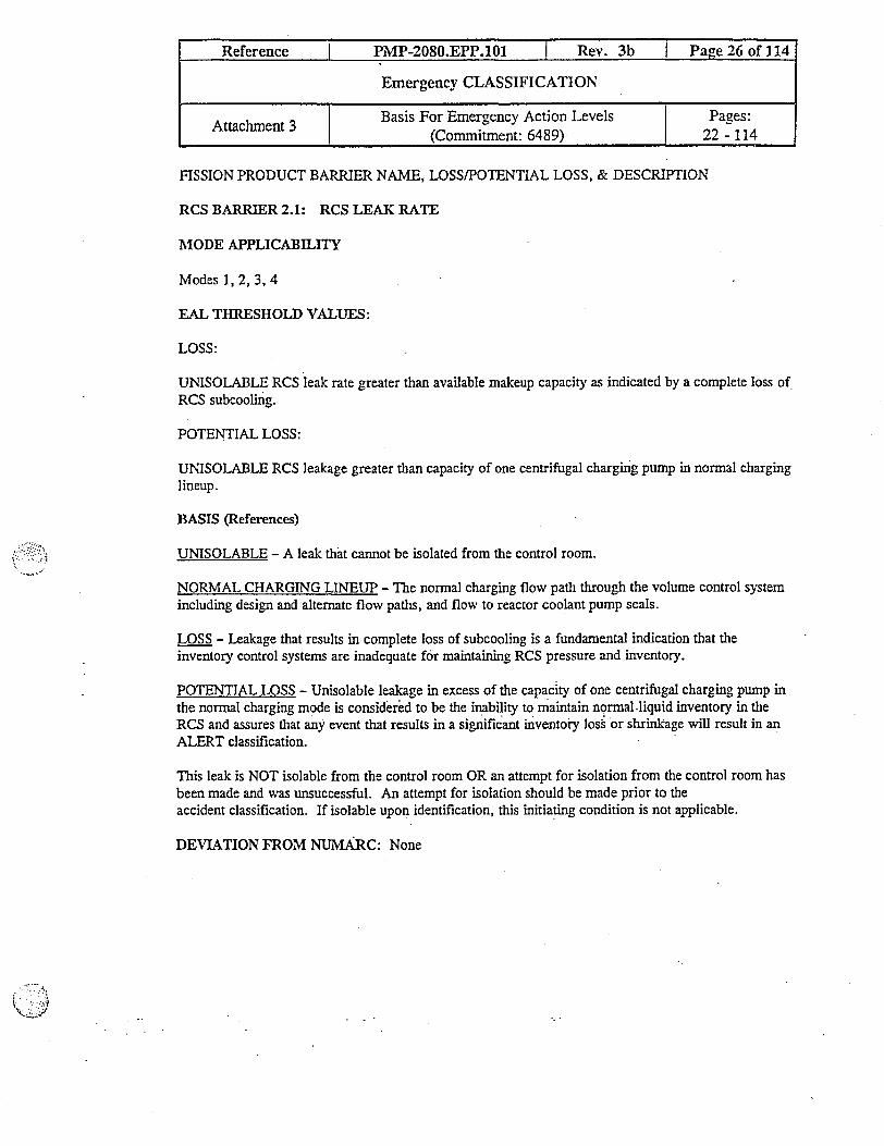
FISSION PRODUCT BARRIER NAME, LOSS/POTENTIAL LOSS, & DESCRIPTION
RCS BARRIER 2.1: RCS LEAK RATE
MODE APPLICABILITY
Modes 1, 2, 3, 4
EAL THRESHOLD VALIES:
LOSS:
UNISOLABLE RCS leak rate greater than available makeup capacity as indicated by a complete loss ofRCS subcooling.
POTENTIAL LOSS:
UNISOLABLE RCS leakage greater than capacity of one centrifugal charging pump in normal charginglineup.
BASIS (References)
UNISOLABLE - A leak that cannot be isolated from the control room.
NORMAL CHARGING LINEUP - The normal charging flow path through the volume control systemincluding design and altemate flow paths, and flow to reactor coolant pump seals.
LOSS - Leakage that results in complete loss of subcooling is a fundamental indication that theinventory control systems are inadequate for maintaining RCS pressure and inventory.
POTENTIAL LOSS - Unisolable leakage in excess of the capacity of one centrifugal charging pump inthe normal charging mode is considered to be the inabiity to maintain normal .liquid inventory in theRCS and assures that any event that results in a significant inventory loss or shrinkage will result in anALERT classification.
This leak is NOT isolable from the control room OR an attempt for isolation from the control room hasbeen made and was unsuccessful. An attempt for isolation should be made prior to theaccident classification. If isolable upon identification, this initiating condition is not applicable.
DEVIATION FROM NUMARC: None

FISSION PRODUCT BARRIER NAME, LOSS/POTENTIAL LOSS, & DESCRIPTION
RCS BARRIER 2.2: STEAM GENERATOR LEAKAGE
MODE APPLICABILITY
Modes 1, 2, 3, 4
EAL THRESHOLD VALUE
LOSS:
Entry into OHP-4023.E-3, "Steam Generator Tube Rupture" AND a non-isolable secondary line breakresulting in a prolonged release (> 30 minutes) radioactive release to the environment from the affectedsteam generator.
POTENTIAL LOSS:
Ruptured steam generator with primary to secondary leak rate greater than capacity of one chargingpump in normal charging mode.
BASIS (References)
NORMAL CHARGING MODE - The normal charging flow path through volume control systemincluding design and alternate flow paths, and flow to reactor coolant pump seals.
LOSS - This is intended to address the full spectrum of steam generator tube rupture events andaddresses the direct release of radioactive material to the environment. Dose assessment is requiredwhen there is indication that the fuel matrix/clad is potentially lost. This EAL encompasses steambreaks, feed breaks, and stuck open safety or relief valves. The assumed break flow termination timeperiod in our steam generator tube rupture dose consequence analysis is 30 minutes; therefore, 30minutes is used to define prolonged.
POTENTIAL LOSS - Unisolable leakage in excess of the capacity of one centrifugal charging pump inthe normal charging mode is considered to be the inability to maintain normal liquid inventory in theRCS and assures that any event that results in a significant inventory loss or shrinkage will result in anALERT classification.
DEVIATION FROM NUMARC: None
Reference I PMP-2080.EPP.101 I Rev. 3b I Page 27 of 114
Emergency CLASSIFICATION
Attachment 3 | Basis For Emergency Action Levels Pages:I (Commitnent: 6489) 22 - 114

FISSION PRODUCT BARRIER NAME, LOSS/POTENTIAL LOSS, & DESCRIPTION
RCS BARRIER 2.3: CONTAINIENT RADIATION
MODE APPLICABILITY
Modes 1, 2, 3, 4
EAL THRESHOLD VALUE
LOSS:
Containment radiation greater than 10 R/hr.
POTENTIAL LOSS:
None
BASIS (References)
LOSS - A value of 10 R/hr as indicated on VRA 1310/1410 (Unit 1) and VRA02310/2410 (Unit 2) waschosen because it is above the ambient background radiation and represents a detectable radiation levelabove allowed Technical Specification radiochemistry limits but less than the 2-5% fuel clad damageused in the fuel clad fission product barrier threshold value.
The 10 R/hr value was determined on the basis of the Donald C. Cook Core Damage Assessmentmethodology, taking into account that the radiation levels resulting from noble gases released from thecoolant will vary as a function of core shutdown time. The reading is based on noble gas reading aloneapproximately 90 minutes after reactor shutdown. This assumption is consistent with the current coredamage assessment methodology for the Donald C. Cook Nuclear Plant.
The use of noble gases alone for a EAL threshold is conservative since if iodine or other radioactivematerials were present, the doses would be higher. The use of a value reflecting a plant shutdown ofone hour was selected as a reasonable reflection of the phenomena being considered-without concernabout setting the threshold too high or too low. The actual fission product barrier threshold will bedeclared at any time the value indicated is exceeded.
POTENTIAL LOSS - None
DEVIATION FROM NUMARC:
Calculation of radiation monitor reading is based on dispersal of noble gases only (iodine inventory notincluded) from the reactor coolant.
Reference I PMP-2080.EPP.101 l Rev. 3b I Page 28 of 114
Emergency CLASSIFICATION
Attachment 3 | Basis For Emergency Action Levels Pages:(Commitment: 6489) 1 22 - 114

FISSION PRODUCT BARRIER NAME, LOSS/POTENTIAL LOSS, & DESCRIPTION
RCS BARRIER 2.4: RCS INTEGRITY CSFST
MODE APPLICABILITY
1,2,3,4
EAL THRESHOLD VALUUE
LOSS: None
POTENTIAL LOSS:
RCS Integrity Critical Safety Function Status Tree - RED
.BASIS (References)
LOSS - None
POTENTIAL LOSS -
The RCS Integrity Critical Safety Function RED indicates an extreme challenge to the safety functionand a potential loss of the RCS barrier.
DEVIATION FROM NUMARC: None
Reference PMP-2080.EPP.101 Rev. 3b I Page 29 of 114
Emergency CLASSIFICATION
Attachmnent 3 Basis For Emergency Action Levels Pages:(Commitment: 6489) I 22 - 114
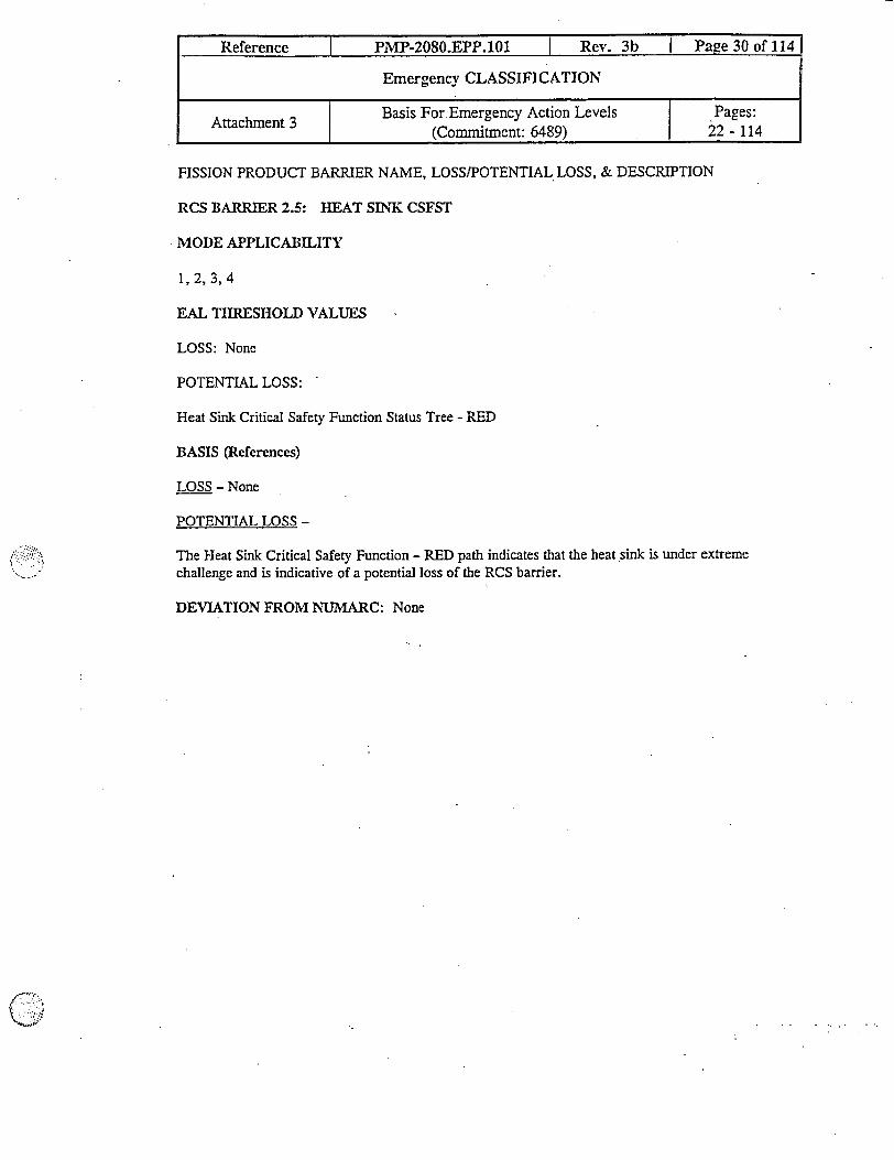
Reference PMP-2080.EPP.101 Rev. 3b Page 30 of 114
Emergency CLASSIFICATION
Attachment 3 Basis For Emergency Action Levels Pages:(Commitment: 6489) 22 - 114
FISSION PRODUCT BARRIER NAME, LOSS/POTENTIAL LOSS, & DESCRIPTION
RCS BARRIER 2.5: HEAT SINK CSFST
MODE APPLICABILITY
1,2,3,4
EAL THRESHOLD VALUES
LOSS: None
POTENTIAL LOSS:
Heat Sink Critical Safety Function Status Tree - RED
BASIS (References)
LOSS - None
POTENTIAL LOSS -
The Heat Sink Critical Safety Function - RED path indicates that the heat sink is under extremechallenge and is indicative of a potential loss of the RCS barrier.
DEVIATION FROM NUMARC: None

FISSION PRODUCT BARRIER NAME, LOSS/POTENTIAL LOSS, & DESCRIPTION
CONTAINMENT BARRIER 3.1 - CONTAINMENT RADIATION
MODE APPLICABILITY
1, 2,3,4
EAL THRESHOLD VALUE
LOSS:
None
POTENTIAL LOSS:
Containment Radiation greater than 1000 R/hr.-OR-
Assessment of core damage greater than 20 % clad failure
BASIS (References)
LOSS - None
POTENTIAL LOSS - The 1000 R/hr value is based on a reasonable assessment of a single numberrepresenting the expected monitor reading on the upper containment high range area radiation monitorsVRA 1310/1410 (Unit 1) or VRA 2310/2410 (Unit 2). The reading represents the expected reading forloss of coolant accidents with 20% fuel clad damage.
The 1000 R/hr value was determined on the basis of the Donald C. Cook Core Damage AssessmentMethodology, taking into account that the radiation levels resulting from the release of noble gasesfrom failed fuel will vary as a function of core shutdown time. As with the RCS and Fuel Clad barrierscontaimnent radiation EALs, this reading is based on release of noble gases only, approximately 90minutes after shutdown.
DEVIATION FROM NUMARC;
Calculation of radiation monitor reading is based on dispersal of noble gases only (iodine inventory notincluded) from the reactor coolant.
Reference I PMP-2080.EPP.101 I Rev. 3b I Page 31 of 114
Emergency CLASSIFICATION
Attachment 3 Basis For Emergency Action Levels Pages:I I (Comitment: 6489) 1 22-114
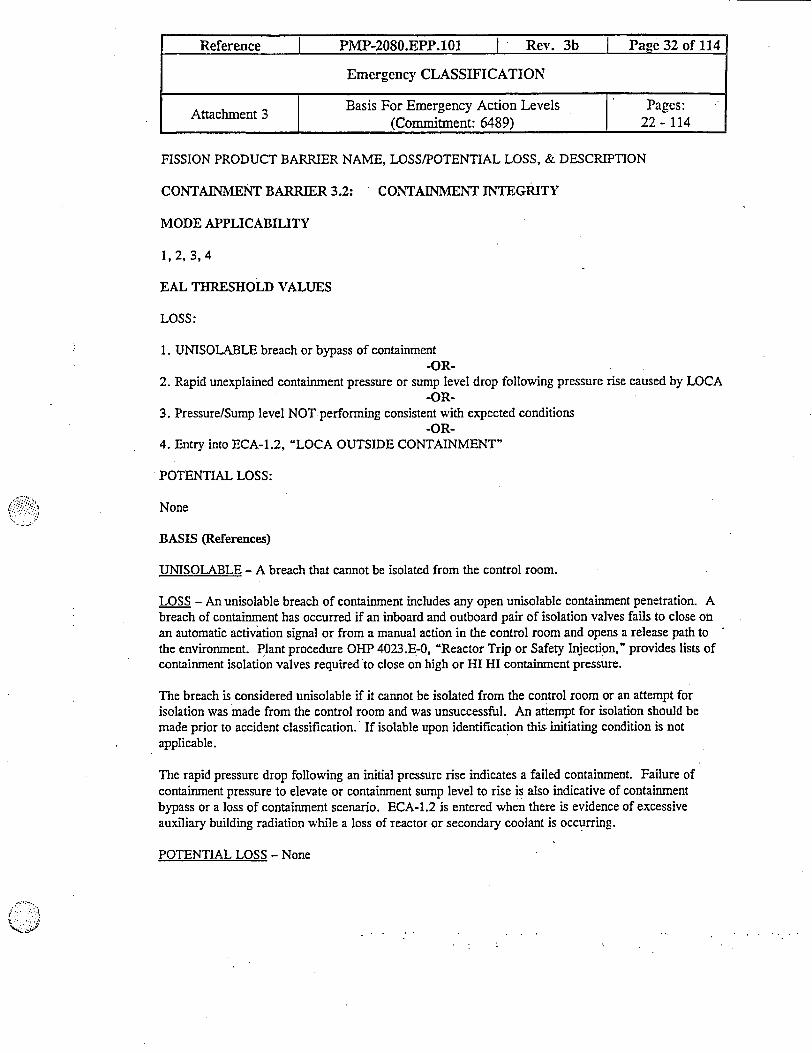
FISSION PRODUCT BARRIER NAME, LOSS/POTENTIAL LOSS, & DESCRIPTION
CONTAINMENT BARRIER 3.2: CONTAINMENT INTEGRITY
MODE APPLICABILITY
1,2, 3,4
EAL THRESHOLD VALUES
LOSS:
1. UNISOLABLE breach or bypass of containment-OR-
2. Rapid unexplained containment pressure or sump level drop following pressure rise caused by LOCA-OR-
3. Pressure/Sump level NOT performing consistent with expected conditions-OR-
4. Entry into ECA-1.2, LOCA OUTSIDE CONTAINMENT"
POTENTIAL LOSS:
None
BASIS (References)
UNISOLABLE - A breach that cannot be isolated from the control room.
LOSS - An unisolable breach of containment includes any open unisolable containment penetration. Abreach of containment has occurred if an inboard and outboard pair of isolation valves fails to close onan automatic activation signal or from a manual action in the control room and opens a release path tothe environment. Plant procedure OHP 4023.E-0, "Reactor Trip or Safety Injection," provides lists ofcontainment isolation valves required to close on high or HI HI containment pressure.
The breach is considered unisolable if it cannot be isolated from the control room or an attempt forisolation was made from the control room and was unsuccessful. An attempt for isolation should bemade prior to accident classification. If isolable upon identification this. initiating condition is notapplicable.
The rapid pressure drop following an initial pressure rise indicates a failed containment. Failure ofcontainment pressure to elevate or containment sump level to rise is also indicative of containmentbypass or a loss of containment scenario. ECA-1.2 is entered when there is evidence of excessiveauxiliary building radiation while a loss of reactor or secondary coolant is occurring.
POTENTIAL LOSS - None
Reference I PMP-2080.EPP.101 I Rev. 3b I Page 32 of 114
Emergency CLASSIFICATION
Attachmnent 3 | Basis For Emergency Action Levels Pages:I ~ (Commitment: 6489) 22 - 114

Reference I PMP-2080.EPP.101 I Rev. 3b I Page 33 of 114
Emergency CLASSIFICATION
Attachment 3 Basis For Emergency Action Levels Pages:(Commitment: 6489) 22 - 114
DEVIATION FROM NUMARC: None

FISSION PRODUCT BARRIER NAME, LOSS/POTENTIAL LOSS, & DESCRIPTION
CONTTAINMENT BARRIER 3.3 - STEAM GENERATOR SECONDARY SIDE RELEASE
MODE APPLICABILITY
1, 2, 3,4
EAL THRESHOLD VALUE
LOSS:
la. Primary to secondary leakage rate greater than technical specification limit.
AND
b. Secondary line break outside containment results in release (>30 minutes) to the environment.
OR
2. Release of secondary coolant from the associated steam generator to the environment isoccurring with an alert alarm on any SG PORV radiation monitor.
POTENTIAL LOSS:
None
BASIS (References)
NORMAL CHARGING LINEUP - The normal charging flow path through the volume control systemincluding design and alternate flow paths, and flow to reactor coolant pump seals.
LOSS - Secondary side release paths to the environment include atmospheric relief valves and mainsteam safety valves. Site Area Emergency declaration will be based on evidence of elevated RCSactivity as indicated by SG PORV radiation monitor alert alarm. The SG PORV radiation monitor alertalarm setpoint corresponds to SAE site boundary dose rate.
For smaller breaks, not exceeding the capacity of one charging pump in the NORMAL CHARGINGMODE, an UNUSUAL EVENT classification will result if the ruptured steam generator is isolated.For larger breaks, if the steam generator remains unisolated, this EAL will be a discriminator for SITEAREA AND GENERAL EMERGENCIES. The threshold for Site Area Emergency is based onelevated RCS activity indicated by an alert alarm on a SG PORV radiation monitor.
Reference I PMP-2080.EPP.101 I Rev. 3b I Page 34 of 114
Emergency CLASSIFICATION
Attachmnent 3 t Basis For Emergency Action Levels Pages:I (Commitment: 6489) 22 - 114

v If the MSIV on the affected SG is stuck open, the classification is not upgraded to a Site AreaEmergency unless there are other complicating factors present. Any complicating factors presentshould be considered in order to determine if the tube rupture should be classified as a Site AreaEmergency. These factors may include, but are not limited to, elevated RCS activity (300 Pc/cc I-131 dose equivalent indicates significant failed fuel, > 1 %), or significant unisolable steam leakagedownstream of the MSIV.
SEC judgement should be used when evaluating the steam leak size and any other complicatingfactors that are not specifically addressed in the EAL, when making the determination to classifythe tube rupture as a Site Area Emergency.
POTENTIAL LOSS
None
DEVIATION FROM NUMARC:
NUMARC does not use the elevated RCS activity as discriminator for Site Area Emergency.
Reference I PMP-2080.EPP.101 I Rev. 3b I Page 35 of 114
Emergency CLASSIFICATION
Attachment 3 Basis For Emergency Action Levels Pages:Attachmen 3 |(Commitment: 6489) | 22 - 114
FISSION PRODUCT BARRIER NAME, LOSS/POTENTIAL LOSS, & DESCRIPTION
CON'TAINMENT BARRIER 3.4 - CONTAINMENT CRITICAL SAFETY FUNCTION STATUSTREE
MODE APPLICABILITY
1, 2, 3,4
EAL THRESHOLD VALUE
LOSS:
None
POTENTLAL LOSS:
Containment critical safety function status tree - RED
BASIS (References)
LOSS - None
POTENTIAL LOSS - The RED path indicates an extreme challenge to the containment and representsa potential loss of containment.
In addition to a containment isolation system, the Cook Nuclear Plant design includes an ice condensersystem, containment air recirculation hydrogen skimmer fans, containment spray system, and an RHRsystem. The lower containment high pressure setpoint is 1.1 psig at which a partial containmentisolation will occur and the containment air recirculation fans are automatically started after a short timedelay. Containment spray is automatically started when containment pressure reaches its HI HIpressure of 2.9 psig. RHR spray will be initiated if both containment spray trains are not running and50 minutes has elapsed since the reactor trip. This 12 psig value is also the containment pressure whichindicates Containment Critical Safety Function Status Tree - RED, this EAL indicates the potential ofthe containment exceeding its design pressure of 12 psig, hence the potential of loss of containment.
DEVIATION FROM NUMARC: None
Reference I PMP-2080.EPP.101 | Rev. 3b I Page 36 of 114
Emergency CLASSIFICATION
Attachment 3 Basis For Emergency Action Levels Pages:I | (Commitment: 6489) 22 - 114
FISSION PRODUCT BARRIER NAME, LOSS/POTENTIAL LOSS, & DESCRIPTION
CONTAINMENT BARRIER 3.5: CONTAINMENT HYtDROGEN
MODE APPLICABILITY
1, 2, 3,4
EAL THRESHOLD VALUES
LOSS:
Initiating conditions for LOSS included under initiating conditions for loss of FPB 3.2,CONTAINMENT INTEGRITY.
POTENTIAL LOSS:
1. Hydrogen greater than 4.0%-OR-
2. Containment hydrogen concentration greater than 0.5 % AND any hydrogen control equipment(Containment air recirculation/hydrogen skimmer systems, electric hydrogen recombiner OR igniters)inoperable.
BASIS (References)
LOSS - None
POTENTIAL LOSS : Cook Nuclear Plant is a Westinghouse plant with an ice condenser containment.Due to its smaller volume than comparable plants with dry containments, it relies more heavily onengineered safety features for overpressure protection than do dry containments. Overpressure may becaused by buildup of steam or noncondensibles in containment, or the consequences associated withignition of hydrogen gas in the containment.
The potential for loss of containment may be caused by the accumulation of hydrogen gas and theinability of at least one train of required safety components required for the control of hydrogen gas tobe inoperable. A 0.5 % or greater volume percent is indicative that significant hydrogen gas has formedin containment, and control measures are warranted. Equipment to limit accumulation of hydrogenincludes the containment air recirculation fans and the containment air recirculation/hydrogen skimmersystem. Failure of this equipment is indicative of accumulating percentages of hydrogen until 4 volumepercent, the lower flammability limit for hydrogen gas is exceeded. Above this percentage, thehydrogen igniters are the principal equipment relied on to reduce hydrogen gas concentration to below4 percent.
Reference I PMP-2080.EPP.101 I Rev. 3b I Page 37 of 114
Emergency CLASSIFICATION
Attachment 3 Basis For Emergency Action Levels Pages:Attachment 3 (ComIitment: 6489) 22 - 114

DEVIATION FROM NUMARC:
A threshold value has been added for hydrogen concentration greater than 0.5% and key hydrogencontrol equipment inoperable.
JI
Reference I PMP-2080.EPP.101 I Rev. 3b I Page 38 of 114
Emergency CLASSIFICATION
Attachment 3 Basis For Emergency Action Levels Pages:I (Commitment: 6489) | 22 - 114
FISSION PRODUCT BARRIER NAME, LOSS/POTENTIAL LOSS, & DESCRIPTION
CONTAINMENT BARRIER 3.6 - CONTAINMENT PRESSURE CONTROL
MODE APPLICABILITY
1,2,3,4
EAL THRESHOLD VALUES
LOSS:
Initiating conditions for LOSS included under initiating conditions for loss of FPB 3.3,CONTAINMENT INTEGRITY.
POTENTIAL LOSS:
1. Both containment spray systems both inoperable OR fail to automatically actuate on HI-HIcontainment pressure.
-OR-2. Both containment air recirculation fans inoperable OR fail to automatically actuate on HIcontainment pressure.
-OR-3. Containment pressure exceeds 12 psig.
BASIS (References)
LOSS - None
POTENTIAL LOSS - Cook Nuclear Plant is a Westinghouse plant with an ice condenser containment.Due to its smaller volume than comparable plants with dry contaimnents, it relies more heavily onengineered safety features for overpressure protection than do dry containrnents. Overpressure may becaused by buildup of steam or noncondensibles in containment, or the consequences associated withignition of hydrogen gas in the containment.
Containment pressure control is achieved through the Containment Spray system and the ContainmentAir Recirculation/hydrogen skimmer system. Total failure of both these systems may allow steam tobuild up within containment, and, unabated, this steam buildup may cause the internal containmentpressure buildup to exceed the design pressure of 12 psig. Studies have shown that the containment canwithstand pressures well above this value.
Both the recirculation fans and the containment spray pumps are actuated atuomatically followingreceipt of a HI or HI HI containment pressure signal, respectively. However, rapid startup of thesesystems is not required, since the ice condenser will serve as a passive steam pressure reduction device
Reference PMP-2080.EPP.101 I Rev. 3b I Page 39 of 114
Emergency CLASSIFICATION
Attachment 3 Basis For Emergency Action Levels Pages:(Commitment: 6489) 22- 114
until the ice has melted. Therefore, if these systems should fail, it is pernissible to start both thesesystems manually without being overly concerned about the potential loss of containment due tooverpressure. However, the failure of automatic startup of redundant equipment is consideredsymptomatic of potentially degraded key safety equipment. Thus the potential loss categorization willremain until it can be determined that the failure to start automatically was not symptouiatic of majorsystem degradation.
DEVIATION FROM NUMARC:
None.
Reference I PMP-2080.EPP.101 I Rev. 3b I Page 40 of 114
Emergency CLASSIFICATION
Basis For Emergency Action Levels Pages:Attachment 3
I ~ (Commitment: 6489) 22 -114
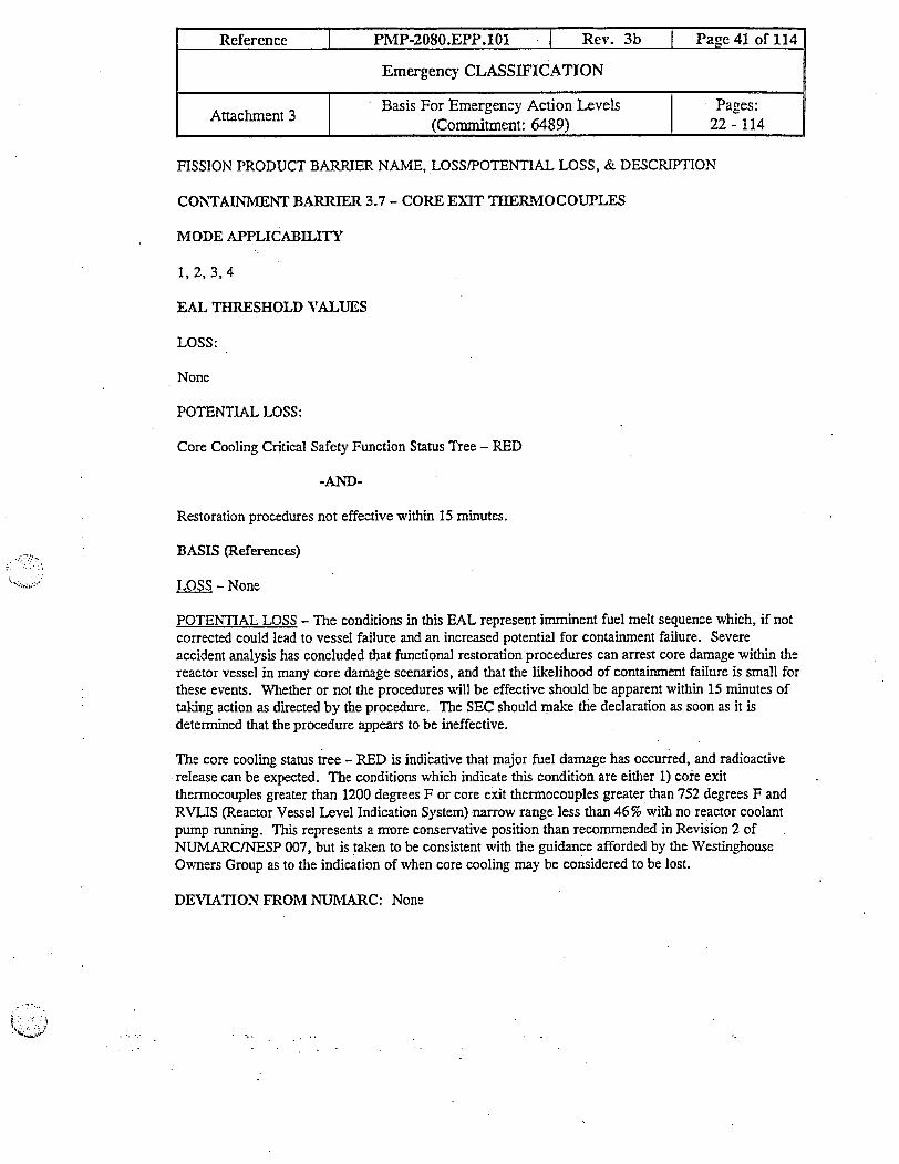
FISSION PRODUCT BARRIER NAME, LOSS/POTENTIAL LOSS, & DESCRIPTION
CONTAINMENT BARRIER 3.7 - CORE EXIT THERMOCOUPLES
MODE APPLICABILITY
1, 2, 3,4
EAL THRESHOLD VALUES
LOSS:
None
POTENTIAL LOSS:
Core Cooling Critical Safety Function Status Tree - RED
-AND-
Restoration procedures not effective within 15 minutes.
BASIS (References)
LOSS - None
POTENTIAL LOSS - The conditions in this EAL represent inminent fuel melt sequence which, if notcorrected could lead to vessel failure and an increased potential for containment failure. Severeaccident analysis has concluded that functional restoration procedures can arrest core damage within thereactor vessel in many core damage scenarios, and that the likelihood of containment failure is small forthese events. Whether or not the procedures will be effective should be apparent within 15 minutes oftaking action as directed by the procedure. The SEC should make the declaration as soon as it isdetermined that the procedure appears to be ineffective.
The core cooling status tree - RED is indicative that major fuel damage has occurred, and radioactiverelease can be expected. The conditions which indicate this condition are either 1) core exitthermocouples greater than 1200 degrees F or core exit thernocouples greater than 752 degrees F andRVLIS (Reactor Vessel Level Indication System) -narrow range less than 46% with no reactor coolantpunp running. This represents a mrore conservative position than recommended in Revision 2 ofNUMARC/NESP 007, but is taken to be consistent with the guidance afforded by the WestinghouseOwners Group as to the indication of when core cooling may be considered to be lost.
DEVIATION FROM NUMARC: None
Reference I PMP-2080.EPP.101 - Rev. 3b I Page 41 of 114
Emergency CLASSIFICATION
Basis For Emergency Action Levels Pages:Attachment I (Commitment: 6489) 22 - 114

ECC CATEGORY NAME, EMERGENCY CLASS, AND DESCRIPTION
H-1: UNUSUAL EVENT - SEC JUDGEMENT
INITIATING CONDITION
Other conditions existing which in the judgement of the Site Emergency Coordinator (SEC) warrantdeclaration of an Unusual Event.
MODE APPLICABILITY
All
EAL THRESHOLD VALUE
In the judgement of the SEC, conditions indicate a potential degradation of the level of safety of theplant.
BASIS (References)
This ECC is intended to address unanticipated conditions not addressed explicitly elsewhere but thatwarrant declaration of an emergency because conditions exist which are believed by the SEC to fallunder the Unusual Event emergency class..
From a broad perspective, one area that may warrant SEC judgement is related to likely or actualbreakdown of site specific event mitigating actions. Examples to consider include inadequateemergency response procedures, transient response either unexpected or not understood, failure orunavailability of emergency systems during an accident in excess of that assumed in accident analyses,or insufficient availability of equipment and/or support personnel.
Specific examples of actual events that may require SEC judgement for Unusual Event declaration arelisted here for consideration. However, this list is by no means all inclusive and is not intended to limitthe discretion of the SEC.
* Aircraft crash on -site but, outside the protected area.
* Train derailment on-site but, outside the protected area.
* Near-site explosion which may adversely affect normal site activities but, doesn't directly affectactivities required to maintain safe operation of the plant.
* Near-site releases of toxic or flammable gas which may adversely affect normal site activities but,doesn't directly affect activities required to maintain safe operation of the plant.
Reference I PMP-2080.EPP.101 Rev. 3b Page 42 of 114
Emergency CLASSIFICATION
Ataln 3Basis For Emergency Action Levels Pages:Attachment3 (Commitnent: 6489) - 22 - 114
It is also intended that the SEC's judgement not be limited by any lists of events as defined here. Thislist is provided solely as examples for consideration and it is recognized that actual events may notalways follow a pre-conceived description.
TERMINLTION/RECOVERY CRITERIA
The condition which caused the declaration to be made no longer exists, or in the SEC's judgement, thecondition will not cause a degradation of the level of safety of the plant.
DEVIATION FROM NUMARC: None
Reference PMP-2080.EPP.101 Rev. 3b I Page43 of 114
Emergency CLASSIFICATION
Attachment 3 Basis For Emergency Action Levels Pages:[ Attachment 3 (Commitment: 6489) I 22 - 114
Reference PMP-2080.EPP.101 I Rev. 3b P2ge 44 of 114
Emergency CLASSIFICATION
Basis For Emergency Action Levels Pages:Attachment 3 (Commitment: 6489) 22 - 114
ECC CATEGORY NAME, EMERGENCY CLASS, AND DESCRIPTION
H-1: ALERT - SEC JUDGEMENT
INITIATING CONDITION
Other conditions existing which in the judgement of the Site Emergency Coordinator (SEC) warrantdeclaration of an Alert.
MODE APPLICABILITY
All
EAL THRESHOLD VALUE
In the judgement of the SEC:
1. conditions indicate that plant safety systems may be degraded,-AND-
2. increased monitoring of plant functions is needed.
BASIS (References)
This ECC is intended to address unanticipated conditions not addressed explicitly elsewhere but thatwarrant declaration of an emergency because conditions exist which are believed by the SEC to fallunder the Alert emergency class.
TERMINIATION/RECOVERY CRITERIA
The condition which caused the declaration to be made no longer exists, or in the SEC's judgement, thecondition will not cause a degradation of the level of safety of the plant.
DEVIATION FROM NUMARC: None
ECC CATEGORY NAME, EMERGENCY CLASS, AND DESCRIPTION
H-1: SITE AREA EMERGENCY - SEC JUDGEMENT
INITIATING CONDITION
Other conditions existing which in the judgement of the Site Emergency Coordinator (SEC) warrantdeclaration of a Site Area Emergency.
MODE APPLICABILITY
All
EAL THRESHOLD VALUE
In the judgement of the SEC:
Conditions indicate likely or actual major failures of plant functions needed for the protection of thepublic.
BASIS (References)
This ECC is intended to address unanticipated conditions not addressed explicitly elsewhere but thatwarrant declaration of an emergency because conditions exist which are believed by the SEC to fallunder the Site Area Emergency, emergency classification.
TERMINIATION/RECOVERY CRITERIA
The condition which caused the declaration to be made no longer exists, or in the SEC's judgement, thecondition no longer indicates likely or actual major failures of plant functions needed for the protectionof the public health and safety.
DEVIATION FROM NUMARC: None
Reference PIP-2080.EPP.101 I Rev. 3b I Pace 4 Of 114
Emergency CLASSIFICATION
Attachment 3 Basis For Emergency Action Levels Pages:Attachment 3 (Commitment: 6489) .22 - 114

Reference 7 PMP-2080.EPP.101 Rev. 3b Page 46 of 114
Emergency CLASSIFICATION
Attachment 3 Basis For Emergency Action Levels | Pages:_ Attachment 3 (Commitment: 6489) 22-114
ECC CATEGORY NAME, EMERGENCY CLASS, AND DESCRIPTION
H-1: GENERAL EMERGENCY - SEC JUDGEMENT
INITIATING CONDITION
Other conditions existing which in the judgement of the Site Emergency Coordinator (SEC) warrantdeclaration of a General Emergency.
MODE APPLICABILITY
All
EAL THRESHOLD VALUE
In the judgement of the SEC:
1. Condition indicate an actual or imminent substantial core degradation with potential loss of affectedunit's containment.
-OR-2. Potential exists for an uncontrolled radioactive release that may exceed EPA limits at the siteboundary.
BASIS (References)
The ECC is intended to address unanticipated conditions not addressed explicitly elsewhere but thatwarrant declaration of an emergency because conditions exist which are believed by the SEC to fallunder the General Emergency, emergency classification.
TERMINIATION/RECOVERY CRITERIA
In the SEC's judgement, a General Emergency no longer exists and entry into recovery procedures isappropriate. The affected unit has achieved a cold shutdown.
DEVIATION FROM NUMARC: None'

D ECC CATEGORY NAME, EMERGENCY CLASS, AND DESCRIPTION
H-2: UNUSUAL EVENT - SECURITY EVENTS
INITIATING CONDITION
Confirmed Security Event which indicates a potential degradation in the level of safety of the plant.
MODE APPLICABILITY
All
EAL THRESHOLD VALUE
1. Bomb device discovered within the protected area and outside the vital area.
-OR-
2. Credible bomb threat.
-OR-
3. Credible attack threat.
-OR-
4. Hostage/Extortion incident potentially affecting plant operations.
BASIS (References)
This EAL is based on the Modified Amended Security Plan (MASP). Security events which do notrepresent at least a potential degradation in the level of safety of the Plant, are reported under 10 CFR73.71 or in some cases, under 10 CFR 50.72. The plant protected area boundary is the area within thesecurity isolation zone as defined in the Modified Amended Security Plan. Bomb devices discoveredwithin the plant vital area would result in EAL escalation.
TERMINIATION/RECOVERY CRITERIA
The hazard to the level of safety of the plant no longer exists.
DEVIATION FROM NUMARC: None
Reference I PMP-2080.EPP.101 I Rev. 3b Page 47 of 114
Emergency CLASSIFICATION
Attc n 3Basis For Emergency Action Levels Pages:Attachment 3 | (Commitment: 6489) | 22 - 114

ECC CATEGORY NAME, EMERGENCY CLASS, AND DESCRIPTION
H-2: ALERT - SECURITY EVENTS
INITIATING CONDITION
Security Event in a Plant Protected Area.
MODE APPLICABILITY
All
EAL THRESHOLD VALUTE
1. Intrusion into protected area by a hostile force.
-OR-
2. Civil disturbance within the protected area.
BASIS (References)
This class of security events represent an escalated threat to plant safety above that contained in theUnusual Event. Intrusion into a vital area by a hostile force will escalate this event to a Site AreaEmergency.
TERMINIATION/RECOVERY CRITERIA
Challenge to the safety of the plant no longer exists.
DEVIATION FROM NUMARC: None
Reference I PMP-2080.EPP.101 I Rev. 3b I Page 48 of 114
[ Emergency CLASSIFICATION
Attachment 3 Basis For Emergency Action Levels Pages:l (Commitment: 6489) 1 22 - 114
ECC CATEGORY NAME, EMERGENCY CLASS, AND DESCRIPTION
H-2: SITE AREA EMERGENCY - SECURITY EVENTS
INITIATING CONDITION
Security event in a plant vital area.
MODE APPLICABILITY
All
EAL THRESHOLD VALUE
1. Intrusion into any vital area by a hostile force.
-OR-
2. A security event which results in the loss of control of any vital area (other than the control room).
-OR-
3. A confirmed bomb device discovered in a vital area.
BASIS (References)
This class of security events represents an escalated threat to plant safety above that contained in theAlert IC in that a hostile force has progressed from the protected area to a vital area.
TERMINIATION/RECOVERY CRITERIA
The condition causing the event has been eliminated.
DEVIATION FROM NUMARC: None'
Reference I PMP-2080.EPP.101 I Rev. 3b I Page 49 of 114
Emergency CLASSIFICATION
Attachrnent 3 Basis For Emergency Action Levels Pages:Attachment 3 (Commitment: 6489) 1 22 - 114

ECC CATEGORY NAME, EMERGENCY CLASS, AND DESCRIPTION
H-2: GENERAL EMERGENCY - SECURITY EVENTS
INITIATING CONDITION
Security Event resulting in loss of ability to reach and maintain cold shutdown.
MODE APPLICABILITY
All
EAL THRESHOLD VALUE
1. Loss of physical control of the control room due to a security event.
-OR-
2. Loss of physical control of a unit's remote shutdown capability due to a security event.
BASIS (References)
This Initiating Condition encompasses conditions under which a hostile force has taken physical controlof either the control room or all remote shutdown capabilities resulting in a loss of physical control ofthe facility. This EAL is an escalation of the Site Area Emergency declaration for a hostile forceintrusion into a vital area.
TERMNIATION/RECOVERY CRITERIA
The security threat has been eliminated and cold shutdown can be maintained.
DEV7IATION FROM NUMARC: None
Reference I PMP-2080.EPP.101 l Rev. 3b I Paoe 50 of 114
Emergency CLASSIFICATION
Basis For Emergency Action Levels Pages:Attachment 3 (Commitment: 6489) 22 - 114

ECC CATEGORY NAME, EMERGENCY CLASS, AND DESCRIPTION
H-3: ALERT - CONTROL ROOM EVACUATION
INITIATING CONDITION
Control room evacuation has been initiated.
MODE APPLICABILITY
All
EAL THRESHOLD VALUE
Control room evacuation has been initiated.
BASIS (References)
CONTROL - Placing all local controls in position necessary for operation from remote panels and theshift supervisor has deterrnined that the systems for controlling reactivity, RCS inventory, RCStemperature, and the heat sink functions have been established.
Evacuation of the control room represents a potential for substantial degradation in the level of safety ofthe plant and, therefore, requires an ALERT declaration. Additional support, monitoring, and directionis required and accomplished by activation of the Technical Support Center at the Alert classificationlevel. Inability to establish plant CONTROL from outside the control room will escalate the event to aSite Area Emergency.
Cook Nuclear Plant has separate control rooms for each unit. The Cook Nuclear Plant proceduregoverning control room evacuation and establishing plant control outside the control room is (01-forUnit 1, 02-for Unit 2) OHP 4025.001.001, "Emergency Remote Shutdown".
TERMINIATION/RECOVERY CRITERIA
Control of the plant has been reestablished from the control room.
DEVIATION FROM NUMARC: None
Reference PMP-2080.EPP.101 I Rev. 3b I Page 1 of 114
Emergency CLASSIFICATION
Attachment 3 Basis For Emergency Action Levels Pages:Attachment 3 | (Commitment: 6489) 22 - 114
ECC CATEGORY NAME, EMERGENCY CLASS, AND DESCRIPTION
H-3: SITE AREA EMERGENCY - CONTROL ROOM EVACUATION
INITIATING CONDIITON
Control room evacuation has been initiated and plant CONTROL cannot be established.
MODE APPLICABILITY
All
EAL THRESHOLD VALUE
The following conditions exist:
1. Control Room evacuation has been initiated.
-AND-
2. CONTROL of any one of the following processes is not established within 15 minutes:
. Reactivity* RCS inventory
RCS temperature* SG heat sink
BASIS (References)
CONTROL - Placing all local control switches in local control necessary for operation from remotepanel and the shift supervisor has determined that the systems for controlling reactivity, RCS inventory,RCS temperature, and the heat sink functions have been established.
Cook Nuclear Plant has separate control rooms for each unit. The Cook Nuclear Plant proceduregoverning control room evacuation and esiablishing plant control outside the control room is (01-forUnit 1, 02-for Unit 2) OHP 4025.001.001, "Emergency Remote Shutdown",. The 15 minute timefor CONTROL being established outside of the control room is taken from Revision 2 ofNUMARCINESP 007.
TERMEiIATION/RECOVERY CRITERIA
Control of the plant has been reestablished from the control room.
DEVIATION FROM NUMARC: None
Reference I PMP-2080.EPP.101 Rev. 3b I Page 2 of 114
Emergency CLASSIFICATION
Attachment 3 Basis For Emergency Action Levels Pages:i Attachment 3 (Commitment: 6489) 22 - 114

* The inability to establish control of RCS inventory, RCS temperature, reactivity and heat sinkfunctions at the affected unit's hot shutdown panel within 15 minutes requires the declaration of a sitearea emergency.
Reference I PMP-2080.EPP.101 I Rev. 3b I Page 53 of 114
Emergency CLASSIFICATION
Attachment 3 Basis For Emergency Action Levels Pages:(Commitment: 6489) 22 - 114

ECC CATEGORY NAME, EMERGENCY CLASS, AND DESCRIPTION
H4: UNUSUAL EVENT - FIRE
INITIATING CONDITION
Fire in protected area boundary not extinguished within 15 minutes of detection.
MODE APPLICABILITY
All
EAL THRESHOLD VALUE
Fire within the protected area boundary not extinguished within 15 minutes of detection.
BASIS (References)
The purpose of this EAL is to address only fires which are potentially significant precursors to safetysystem damage. This excludes such items as fires within office buildings, waste basket fires, and othersmall fires of no consequence. This EAL applies to buildings and areas contiguous to plant vital areasor other significant buildings and areas. The intent is not to include buildings (or warehouses) that arenot contiguous or immediately adjacent to areas where safety system performance would be adverselyaffected or there could be an uncontrolled release of radioactive material.
Areas of concern at the Cook Nuclear Plant for this initiating condition (H-1: UNUSUAL EVENT)include the protected area. The radioactive material building (RMB) is not included since it is outsidethe protected area, and not required to safely shutdown the plant. In the unlikely event that a fire wereto occur where 100% of the RMB contained radioactive material were released, it could result in anoffsite dose of 2.5 rem. If a fire or explosion were to occur that could result in an offsite radioactiverelease, the SEC would initially declare as unusual event under the classification requirements of H-5,SEC judgment. The classification could be escalated in accordance with the requirement of R-1, if fieldmeasurements show large offsite releases have actually occurred.
TERMINIATION/RECOVERY CRITERIA
Fire Extinguished.
DEVIATION FROM NUMARC: None
Reference I PMP-2080.EPP.101 I Rev. 3b I Page 54 of 114
Emergency CLASSIFICATION
Attachment 3 | Basis For Emergency Action Levels Pages:Attachment 3 (Commitment: 6489) 1 22 - 114

ECC CATEGORY NAME, EMERGENCY CLASS, AND DESCRIPTION
114: ALERT - FIRE OR EXPLOSION AFFECTING OPERABILITY OF SAFETYEQUIPMENT
INITIATING CONDITION
Fire or explosion affecting OPERABILITY of plant safety systems required to establish or maintainsafe shutdown.
MODE APPLICABILITY
All
EAL THRESHOLD V7ALUE
1. Fire or explosion that affects the OPERABILITY of systems required for the current operatingmode OR for safe shutdown.
-OR-2. Fire or explosion that causes visible damage to any of the following structures: contairunents,
auxiliary buildings, essential service water system enclosures, auxiliary feedwater pump rooms,refueling water storage tank, or condensate storage tank.
BASIS (References)
EXPLOSION - A rapid, violent, uncontained combustion or catastrophic failure of pressurizedequipment that potentially imparts significant energy to nearby structures or equipment.
If a fire affects operability of only one of two redundant systems, then this EAL is not applicable.
The purpose of this EAL is to address only fires which are potentially significant precursors to safetysystem damage. This excludes such items as fires within office buildings, waste basket fires, and othersmall fires of no consequence. This EAL applies to building and areas contiguous to plant vital areasor other significant buildings and areas. The intent is not to include buildings (or warehouses) that arenot contiguous or immediately adjacent to areas where the safety system performance would beadversely affected.
Only explosions of significant force to cause damage (deformation, scorching) to structures orequipment required for safe operation should be considered.
TERMINIATION/RECOVERY CRITERIA
Plant capability to operate safety no longer affected by the event.
DEVIATION FROM NUMARC: None
Reference I PMP-2080.EPP.101 Rev. 3b I Paoe 55 of 114
Emergen'y CLASSIFICATION
Basis For Emergency Action Levels Paaes:(Attachment 3 (Coniitment: 6489) 1 22 -114
ECC CATEGORY NAME, EMERGENCY CLASS, AND DESCRIPTION
H-5: UNUSUAL EVTENT - TOXIC OR FLAMMABLE GASES
INITIATING CONDITION
Release of toxic or flamnmable gases deemed detrimental to safe operation of the plant.
MODE APPLICABILITY
All
NOTE: 1 or 2 OHP-4021-028-014, Operation of the Control Room Air Conditioningand Pressurization/Cleanup Filter System contains instructions for controlroom isolation in the event of a toxic gas release. [Commitment 5572]
EAL THRESHOLD VALUE
1. Release of toxic or flammable gases within or near site boundary that may affect normaloperation of the plant.
-OR-2. Report by local, county, or state officials of potential evacuation of site personnel based on
offsite event.
BASIS (References)
TOXIC - Exposure to the worker in excess of limits specified in 29 CFR 1910.1000. in practice, thisshould be considered for concentrations which are capable of incapacitating the worker.
This initiating condition is based on release in concentrations within the site boundary that will affectthe health and safety of plant personnel or affect safe operation of the plant.
The potential for the degradation in the level of safety of the plant through the affect of toxic ORflamnmable gas on the health of personnel or operation of the plant is to be considered for declaration ofthe UNUSUAL EVENT. The source of the toxic or flammable gas could be from inside or outside thesite.
Although carbon dioxide (C02) concentrations can be lethal, it is not considered a toxic gas for thepurpose of classification unless access is required and cannot be made in an area where equipmentneeded for the safe shutdown of the plant is maintained.
TERMINIATION/RECOVERY CRITERIA
Reference I PMP-2080.EPP.101 Rev. 3b I Paoe 56 of 114
Emergency CLASSIFICATION
Attachment 3 Basis For Emergency Action Levels Pages:I (Commitment: 6489) 1 22 - 114

Reference PMP-2080.EPP.101 Rev. 3b Page 57 of 114
Emergency CLASSIFICATION
Basis For Emergency Action Levels Pages:Attachment 3 (Commitment: 6489) 22 - 114
The release of toxic material is terminated and the operational impact of the release has beeneliminated.
DEVIATION FROM NUMARC: None
ECC CATEGORY NAME, EMERGENCY CLASS, AND DESCRIPTION
H-5: ALERT - TOXIC OR FLAMMABLE GASES
INITIATING CONDITION
Release of toxic of flammable gases within a facility structure which jeopardizes operation of systemsrequired to maintain safe operations or to establish or maintain cold shutdown.
MODE APPLICABILITY
All
NOTE: 1 or 2 OHP4021-028-014, Operation of the Control Room Air Conditioningand Pressurization/Cleanup Filter System contains instructions for controlroom isolation in the event of a toxic gas release. [Commitment 5572]
EAL THRESHOLD VIALUE
1. Report or detection of toxic gases within a facility structure in concentrations that will be lifethreatening to plant personnel.
-OR-
2. Report or detection of flammable gases within a facility structure in concentrations that willaffect the safe operation of the plant.
BASIS (References)
TOXIC - Exposure to the worker in excess of limits specified in 29 CFR 1910.1000. In practice, thisshould be considered for concentrations which are capable of incapacitating the worker.
This EAL is based on gases that have entered plant structures that will affect the safe operation of theplant. These structures include buildings and areas contiguous to plant vital areas and other significantbuildings or area. The intent of this EAL is not to include buildings that are not contiguous orimmediately adjacent to plant vital areas. The source of the toxic or flammable gas could be frominside or outside the site.
The source of the release is not of immediate concern for these threshold values. The concern is for thehealth and safety of plant personnel and their ability to maintain the plant in a safe operating condition.
This EAL is reached whenever the shift manager determines that protective gear is required to be wornby plant personnel required to safely operate the unit.
Reference PMP-2080.EPP.101 Rev. 3g Pane 58 of 114
Emergency CLASSIFICATION
Attachment 3 Basis For Emergency Action Levels Pages:(Commitment: 6489) 22 - 114
Although carbon dioxide (C02) concentrations can be lethal, it is not considered a toxic gas for thepurpose of classification unless access is required and cannot be made in an area where equipmentneeded for the safe shutdown of the plant is maintained.
TERME\IATION/RECOVERY CRITERIA
Plant operations are no longer affected.
DEVIATION FROM NUMARC: None
Reference I PMP-2080.EPP.101 I Rev. 3b I Page 59 of 114
Emergency CLASSIFICATION
Att enBasis For Emergency Action Levels Pages:AItachmentI3 (Commitment: 6489) 22 - 114

ECC CATEGORY NAME, EMERGENCY CLASS, AND DESCRIPTION
N-1 to N-7: UNUSUAL EVENT - NATURAL OR DESTRUCTIVE PHENOMENA ISIDETHE PROTECTED AREA
INITIATING CONDITION
Natural or destructive phenomena inside protected area.
MODE APPLICABILITY
All
EAL THRESHOLD VALlUE
1. CONFIRMED seismic event as indicated by seismic instrument activation or based on groundmotion felt at the nuclear plant and recognized as an earthquake based on consensus of controlroom operators on duty at the time.
-OR-2. Report of a tornado strike within the protected area.
-OR-3. Vehicle collision affecting structures or systems within the protected area.
-OR-4. Main turbine rotating component failure causing visible damage or damage to the generator
seals.-OR-
5. Report by plant personnel of an unanticipated explosion within the protected area boundaryresulting in visible damage to permanent structures or equipment.
BASIS (References)
These threshold values are natural or destructive phenomena which represent potential degradation ofthe level of safety of the plant. The affects of the phenomena should also be evaluated on a system orcomponent basis in relation to the Technical Specifications and evaluated for further classification viaeither site emergency coordinator (SEC) judgement or plant procedures as appropriate.
Threshold Value 1 - Seismic events at the lowest instrument activation, 0.02g (or based on groundmotion felt at the nuclear plant and recognized as an earthquake based on consensus of control roomoperators on duty at the time) may cause damage to systems and represent a potential degradation of thelevel of safety of the plant. A confirmation call to the National Earthquake Center will confirm that anearthquake has occurred ax;d may provide an estimate of the magnitude of the earthquake in the vicinityof Cook Nuclear Plant. Further information regarding anticipated actions may be found in plantprocedures OHP 4022.001.007, Earthquake".
Reference I PMP-2080.EPP.101 I Rev. 3b I Pane 60 of 114
Emergency CLASSIFICATION
Attachment 3 Basis For Emergency Action Levels Pages:AtRachment I (Commitment: 6489) 22 - 114

A call to one of the following may be used to verify/confirm a seismic event. National EarthquakeCenter (phone number (303) 273-8500 or 1-800-525-7848), Local television stations, or, Universitymonitoring stations.
Threshold Value 2 - Any report that a tomado has touched down within the protected area.
Threshold Value 3 - A collision of any vehicle on land, from the air, or on water (plane, train, barge,etc.) which affects structures or equipment within the protected area may potentially damage plantstructures containing functions and systems required for safe shutdown of the plant. If the crash isconfirmed to affect a plant vital area, the event may be escalated to Alert.
Threshold Value 4 - Failure of the rotating components has the potential for leakage of flammablefluids (oil and hydrogen) into the turbine building.
Threshold Value 5 - Only those explosions of sufficient force to damage permanent structures orequipment within the protected area should be considered. As used here an explosion is a rapid,violent, unconfined combustion, or a catastrophic failure of pressurized equipment, that potentiallyimparts significant energy to near-by structures and materials. No attempt is made in the EAL to assessthe actual magnitude of the damage. The occurrence of the explosion with reports of evidence ofdamage (e.g., deformation, scorching) is sufficient for declaration. The SEC also needs to considerany security aspects of the explosion, if applicable.
TERMINIATION/RECOVERY CRITERIA
No further hazard exists, and damage assessment is complete, and termination is allowed in accordancewith the requirements of PMP 2081 EPP.306, De-escalation of Termination of the Emergency andRecovery".
DEVIATION FROM NUMARC:
A separate ECC category name was established for these "Natural or Destructive Phenomena". Theyare included in the 'Hazards And Other Conditions" Category in NUMARC/NESP 007.
Reference | PMP-2080.EPP.101 I Rev. 3b I Pao,e 61 of 114
Emergency CLASSIFICATION
. Attachment 3 Basis For Emergency Action Levels Pages:Attachment 3 8 2
! ~(Cornmitment: 6489) 1 22 -114

ECC CATEGORY NAME, EMERGENCY CLASS, AND DESCRIPTION
N-1 to N-7: ALERT - NATURAL OR DESTRUCTIVE PHENOMENA INSIDE A VITAL AREA
INITIATING CONDITION
Natural or destructive phenomena inside vital areas.
MODE APPLICABILITY
All
EAL THRESHOLD VALUE
1. CONFIRMED seismic event as indicated by seismic instrument activation or based on groundmotion felt at the nuclear plant and recognized as an earthquake based on consensus of controlroom operators on duty at the time AND which causes visible major damage to structures,systems, and components in the vital area or causes a plant trip to occur.
-OR-2. Report of a tornado strike in a plant vital area or SUSTAINED high wind (> 15 min.) greater
than 90 miles per hour.-OR-
3. Report of visible structural damage to a structure containing systems required to establish andmaintain cold shutdown.
-OR-4. Vehicle collision affecting a vital area.
-OR-5. Turbine failure generated missiles penetrating a vital area.
-OR-6. Flooding in a vital area affecting safety related equipment.
BASIS (References)
These threshold values are natural or destructive phenomena which represent actual or potentialsubstantial degradation of the level of safety of the plant. The affects of the phenomena should also beevaluated on a system or component basis in relation to the Technical Specifications and evaluated forfurther classification via either Site Emergency Coordinator (SEC) judgement or plant procedures asappropriate.
Threshold Value 1 - Seismic events at the lowest instrument activation (0.02g ground acceleration) orground motion felt at the nuclear plant and recognized as an earthquake based on consensus of controlroom operators on duty at the time. The effect of the earthquake has significantly affected plantoperations (up to and including manual or automatic plant trip) or has caused visible damage that hasthe potential for major degradation of systems required to maintain the plant in a safe shutdowncondition. A call to the National Earthquake Center will confirm that an earthquake has occurred andmay provide an estimate of the magnitude of the earthquake in the vicinity of the Cook Nuclear Plant.
Reference I PMP-2080.EPP.101 1 Rev. 3b I Paoe 62 of 114
Emergency CLASSIFICATION
Attachment 3 Basis For Emergency Action Levels Pages:(Commitment: 6489) 22 - 114

Operator walkdowns of plant systems, structures and components will be performed to assess potentialdamage levels.
A call to one of the following may be used to verify/confirm a seismic event: National EarthquakeCenter (phone number (303) 273-8500 or 1-800-525-7848), local television stations, or universitymonitoring stations.
Threshold Value 2 - A tornado strike must include an affect on systems or components that affects theoperability or integrity of the system or structure within a vital area. The threshold value of 90 mph isthe FSAR design basis wind load.
Threshold Value 3 - Should be used in conjunction with investigation of threshold values 1 and 2, or ona stand alone basis. A detailed description or assessment of damage is not intended to meet the intentof this threshold value. The list of critical structures is the same as that included under H-4 ALERT(containments, auxiliary buildings, ESW system enclosures, auxiliary feedwater pump rooms, refuelingwater storage tank, condensate storage tank).
Threshold Value 4 - A collision by any vehicle on land, from the air, or on water (plane, train, barge,etc.) which affects structures or equipment within a vital area.
Threshold Value 5 - This threshold value addresses the threat to safety equipment imposed by missilesgenerated by main turbine rotating component failures. This includes all areas classified as vital areasof the plant.
Threshold Value 6 - Flooding in vital areas which affect OPERABILITY of safety related systems orcomponents. The source of the flooding need not be known.
The word OPERABLITY" refers to the definition in the Technical Specifications where requiredredundant safety equipment will be made inoperable. The only types of floods anticipated to triggerthis threshold are major catastrophic pipe ruptures in the plant that have not been previously evaluatedor floods caused by severe external phenomena such as seiches.
TERMINIATION/RECOVERY CRITERIA
No further hazard exists, damage assessment is complete, and termination is allowed in accordance withthe requirements of PMP 2081 EPP.306, "De-escalation or Termination of the Emergency andRecovery".
DEVIATION FROM NUMARC:
A separate ECC category name was established for these "Natural or Destructive Phenomena." Theyare included in the "Hazards And Other Conditions" category in NUMARC/NESP 007.
The EAL for earthquakes does not include a real time seismic instrumentation reading. Cook NuclearPlant seismic instrumentation does not provide indication of the level of earthquake as an Operations
Reference I PMP-2080.EPP.101 I Rev. 3b I Page 63 of 114
Emergency CLASSIFICATION
Attachment 3 Basis For Emergency Action Levels Pages:Attachment 3 (Commitment: 6489) 22 - 114

Basis Earthquake (OBE) or Design Basis Earthquake (DBE). This EAL is written using the operatorassessment method specified in NUMARC/NESP 007.
Reference I PMP-2080.EPP.101 I Rev. 3b I Page 64 of 114
Emergency CLASSIFICATION
Attchn Basis For Emergency Action Levels Pages:I (Commitment: 6489) 22'- 114

ECC CATEGORY NAME, EMERGENCY CLASS, AND DESCRIPTION
R-1: UNUSUAL EVENT - RADIOACTIVE EFFLUENT RELEASE
INITLITING CONDITION
Unplanned release of gaseous or liquid radioactivity to the environment that exceeds two times theODCM release limits for 60 minutes or longer.
MODE APPLICABILITY
All
NOTE: The term "one or more of the following monitors" in the EAL means that thetotal of all monitors is to be considered when classifying an event.[Commitment 5116]
EAL THRESHOLD VALUE
1. A valid reading on one or more of the following monitors that exceeds 2 times the high alarmsetpoint for 60 minutes of longer.
* VRS-1500/2500 (Noble Gas)* SRA-1800/2800 (Noble Gas)* SRA-1900/2900 (Noble Gas)* R-20* R-28
-OR-
2. A VALID radiation monitor reading 2 times the high alarm setpoint for any monitored releasepathway for > 60 minutes.
-OR-
3. Confirmed sample analyses for gaseous or liquid releases indicates concentrations or releaserates exceeding 2 times the ODCM maximum instantaneous release limit for > 60 minutes.
BASIS (References)
VALID - Readings are assumed valid unless circumstances cause the reading to be suspect.Verification can be obtained by a) an instrument channel check, or b) indications on related orredundant indicators, or c) by direct observation by plant personnel. Implicit in this definition is theneed for timely assessment, i.e., within 15 minutes.
Reference PMP-2080.EPP.101 I Rev. 3b I Pace 5 of 114
Emergency CLASSIFICATION
Attachmnent 3 Basis For Emergency Action Levels Pages:Attachment I (Commitment: 6489) I 22 - 114

UNPLANNED - Means the release occurred without a discharge permit or the conditions specified onthe discharge permit have been exceeded.
Environmental release limits for effluent radiation monitor alarms are calculated using methodsspecified in the offsite dose calculation manual (ODCM). An UNPLANNED release in excess of twotimes the ODCM release limit for 60 minutes, or longer, represents an uncontrolled situation, andhence, a potential degradation in the level of safety. Although the final integrated dose is very low inthe Unusual Event emergency class, the degradation in plant control implied by the fact that the releasecannot be terminated in 60 minutes is the primary concem.
Declaration of an Unusual Event should be made as soon as it is determined that the release durationhas or will likely exceed 60 minutes. A dose assessment should be performed to ensure that a higherclassification is not warranted. If the monitor reading(s) is sustained for longer than 60 minutes and therequired assessments cannot be completed within this period, then the declaration must be made basedon the valid reading.
Radioactive gaseous release pathways are monitored by either the unit vent monitor (VRS-1500/2500),the gland steam condenser exhaust effluent monitors (SRA-180012800), the steam jet air ejector venteffluent monitors (SRA-1900/2900), or the steam generator relief monitors. The first three monitorsare included in threshold 1. Steam generator relief monitors are excluded. The reason is thatradioactive gas release via the steam generator PORVs and safety valves is believed to be a pathwaythat could not, under normal operating conditions, lead to release of radioactive gases to theenvironment in sufficient amounts so as to cause exceeding the technical specification limits. The steamgenerator relief monitors are included as an EAL threshold in the site area emergency classification forabnormal release of radioactive materials.
With the exception of possible releases from the essential water system (monitored by R-20 and R-28)release of radioactive liquids to the environment are planned and controlled. Before a batch ofradioactive liquid is released to the environment, the sample is analyzed. If the radioactivity of thesample is within acceptable limits, the liquid will be released, monitored, and recorded. The alarm onthe monitor is set in accordance with ODCM limits. To cover the potential that something may gowrong with the liquid release process, threshold 2 addresses any valid radiation monitor reading.
TERMINIATION/RECOVERY CRITERIA.
The source of the release is determined and isolated (terminated). Environmental field team sampleshave been taken and the environmental impact assessment is in progress.
DEVIATION FROM NUMARC:
Example EALs from NUMARC/NESP 007 numbers 3 and 4 (i.e., perimeter radiation monitoring andreal time dose assessment) were not used because Cook Nuclear Plant does not have those capabilities.
The initiating condition is stated in terms of exceeding ODCM limits rather than exceeding radiologicaltechnical specifications.
Reference PMP-2080.EPP.101 Rev. 3b Pane 66 of 114
Emergency CLASSIFICATION
Attachment 3 Basis For Emergency Action Levels Pages:AttachmentI3 (Commitment: 6489) 22 - 114

ECC CATEGORY NAME, EMERGENCY CLASS, AND DESCRIPTION
R-1: ALERT - RADIOACTIVE EFFLUENT RELEASE
INITIATING CONDITION
Any unplanned release of gaseous or liquid radioactivity to the environment, greater than 200 timesODCM release limits, which lasts for 15 minutes or longer.
MODE APPLICABILITY
All
NOTE: The term 'one or more of the following monitors" in the EAL means that thetotal of all monitors is to be considered when classifying an event.[Commitment 5116]
EAL THRESHOLD VALUE
1. A valid reading on one or more of the following monitors which is greater than 200 times highalarm setpoint for > 15 minutes.
* VRS-1500/2500 (Noble Gas)* SRA-1800/2800 (Noble Gas)* SRA-1900/2900 (Noble Gas)* R-20. R-28
-OR-2. A valid radiation monitor reading indicating 200 times the high alarm setpoint for any
monitored release pathway for > 15 minutes.-OR-
3. Confirmed sample analyses for gaseous or liquid releases indicates concentrations or releaserates exceeding 200 times the ODCM maximum instantaneous release limit for > 15 minutes.
BASIS (References)
VALID - Readings are assumed valid unless circumstances cause the reading to be suspect.Verification can be obtained by a) an instrument channel check or b) indications on related or redundantindicators, or c) by direct observation by plant personnel. Implicit in this definition is the need fortimely assessment, i.e., within 15 minutes.
UNPLANNED - Means the release occurred without a discharge permit or the conditions specified onthe discharge permit have been exceeded.
Reference I PMP-2080.EPP.101 | Rev. 3b I Paoe 67 of 114
Emergency CLASSIFICATION
Basis For Emergency Action Levels Pages:Attachmnent 3 (Commitnent: 6489) | 22 - 114

This event escalates from the Unusual Event by escalating the magnitude of the release by a factor of100. Prorating the 500 mR/yr criterion for both time (8766 hr/yr and the 200 multiplier, the associatedsite boundary dose rate would be 10 niR/hr. The required release duration was reduced to 15 minutesin recognition of the increased severity.
Declaration of an Alert should be made as soon as it is determined that the release duration has or willlikely exceed 15 minutes. A dose assessment should be performed to ensure that a higher classificationis not warranted. If the monitor reading(s) is sustained for longer than 15 minutes and the requiredassessments cannot be completed within this period, then the declaration must be made based on thevalid reading.
Further information on the basis of EAL threshold 1 cited above may be found in the basis documentfor the Unusual Event associated with R-1.
TERMINIATION/RECOVERY CRITERIA
The source of the release is determined and isolated (terminated). Environmental field team sampleshave been taken and the environmental impact assessment is in progress.
DEVIATION FROM NUMARC:
Example EALs from NUMARC/NESP 007 numbers 3 and 4 (i.e., perimeter radiation monitoring andreal time dose assessment) were not used because Cook Nuclear Plant does not have those capabilities.
The initiating condition is stated in terms of exceeding ODCM limits rather than exceeding radiologicaltechnical specifications.
Reference I PMP-2080.EPP.101 I Rev. 3b Page 68 of 114
Emergency CLASSIF1CATION
Attachment 3 Basis For Emergency Action Levels Pages:Attachment 3 (Commitment: 6489) 22 - 114

ECC CATEGORY NAME, EMERGENCY CLASS, AND DESCRIPTION
R-1: SITE AREA EMERGENCY - RADIOACTIVE EFFLUENT RELEASE
INITIATING CONDITION
Site boundary dose resulting from an actual or imminent release of gaseous radioactivity exceeds 100mrem TEDE or 500 mrem thyroid CDE for the actual or projected duration of the release.
MODE APPLICABILITY
All
NOTE: The term "one or more of the following monitors' in the EAL means that thetotal of all monitors is to be considered when classifying an event.[Commitment 5116]
EAL THPESHOLD VALUE
1. Field survey results indicate site boundary dose rates exceeding 100 mRlhr B-y or a CDEthyroid exceeding 500 mrem for 1 hour of inhalation at the site boundary.
-OR-2. A valid dose assessment indicates greater than 100 mrem TEDE or 500 mrem CDE thyroid at
the site boundary.-OR-
3. A valid reading on one or more of the following monitors (noble gas channels) that exceeds oris expected to exceed the value shown indicates that the release may have exceeded the abovecriterion and indicates the need to assess the release in accordance with appropriate plantprocedures.
* VRS-1500/2500 > 1.07 E-1 uci/cc (Unit Vent).* VRS-1800/2800 > 7.90 EOp.ci/cc (Steam Packing Exhauster)* SRA-1900/2900 > 1.95 E+3 tci/cc (Air Ejector)* MRA-1600/2600 > 1.00 E+2 p.ci/cc (SG PORV)
1700/2700
NOTE: The above monitor readings are based on an assumed 1 hour event duration. If the monitorreading(s) is sustained for longer than 15 minutes and the required assessments cannot be completedwithin this period, then the declaration must be based on the valid monitor reading. The monitorranges should be selected in accordance with guidance in PMP 2081 EPP. 106.
BASIS (References)
Reference I PMP-2080.EPP.101 I Rev. 3b I Page 69 of 114
Emergency CLASSIFICATION
Attachment 3 Basis For Emergency Action Levels Pages:I (Commitment: 6489) 1 22 - 114
VALID - Readings are assumed valid unless circumstances cause the reading to be suspect. Radiationreadings can be confirmed by redundant instrumentation, local readings, or grab samples.
The 100 mrem integrated dose in this initiating condition, is based on the 10 CFR 20 annual averagepopulation exposure. This value also provides a desirable gradient (one order of magnitude) betweenthe Alert, Site Area Emergency and General Emergency classes. The 500 mrem CDE thyroid dose isconsistent with the 1.5 ratio of the EPA Protective Action Guidelines for Total Effective DoseEquivalent and Committed Dose Equivalent to the thyroid.
A release duration of 1 hour is assumed. For analysis of longer or shorter duration releases, the 100mrem/hr TEDE and 500 mrem/hr CDE thyroid dose rates should be adjusted accordingly.
The releases on the monitors in threshold #3 above are calculated using the Cook Nuclear Plant DoseAssessment Program (DAP) and are based on average plant meteorology, the assumption that therelease is one hour duration, and a site boundary dose of 100 mrem/hour. Details may be found inAEP Radiological Support Section calculation RS-C-283. Analysis of gaseous releases shorter orlonger duration or different meteorologic conditions is performed during the dose assessment. If themonitor release is sustained for greater than 15 minutes and the dose assessment cannot be completed inthis time period, then emergency classification will be solely on whether the monitor readings are validand whether they exceed the values cited in threshold #3 above.
TERMINIATION/RECOVERY CRITERIA
The source of the release has been determined and isolated (terminated) Environmental field sampleshave been taken and environmental impact assessment is in progress.
DEVIATION FROM NUMARC:
NUMARC/NESP 007 example EAL number 2 (i.e., perimeter radiation monitoring system) was notused because Cook Nuclear Plant does not have that capability.
Reference PMP-2080.EPP.101 I Rev. 3b I Page 70 of 114
Emergency CLASSIFICATION
Attachment 3 Basis For Emergency Action Levels Pages:Attachment 3 (Commitment: 6489) 22 - 114

ECC CATEGORY NAME, EMERGENCY CLASS, AND DESCRIPTION
R-1: GENERAL EMERGENCY - RADIOACTIVE EFFLUENT RELEASE
INITIATING CONDITION
Site boundary dose resulting from an actual or imminent release of gaseous radioactivity exceeds 1000mrem TEDE or 5000 mrem CDE thyroid for the actual or projected duration of the release.
MODE APPLICABILITY
All
NOTE: The term "one or more of the following monitors' in the EAL means that thetotal of all monitors is to be considered when classifying an event.[Commitment 5116]
EAL THRESHOLD VALUE
1. Field survey results indicate site boundary dose rates exceeding 1000 mR/hr P - y or a CDEthyroid exceeding 5000 mrem for 1 hour of inhalation at the site boundary.
-OR-2. A valid dose assessment indicates greater than 1000 mrem TEDE or 5000 mrem CDE thyroid
at the site boundary.-OR-
3. A valid reading on one or more of the following monitors (noble gas channels) that exceeds oris expected to exceed the value shown indicates that the release may have exceeded the abovecriterion and indicates the need to assess the release in accordance with the appropriate plantprocedures.* VRS-1500/2500 > 1.07 E+0 lici/cc (Unit Vent)* SRA-1800/2800 > 1.57 E+2 lici/cc (Steam Packing Exhauster)* SRA-1900/2900 > 5.78 E+3 1ici/cc (Air Ejector)
NOTE: The above monitor readings are based on an assumed 1 hour event duration. If the monitorreading(s) is sustained for longer than 15 minutes and the required assessments cannot be completedwithin this period, then the declaration must be based on the valid ronitor reading. The monitorranges should be selected in accordance with guidance in PMP 2081 EPP. 106.
BASIS (References)
VALID - Readings are assumed valid unless circumstances cause the reading to be suspect.Verification can be obtained by a) an instrument channel check, or b) indications on related orredundant indicators, or c) by direct observation by plant personnel. Implicit in this definition is theneed for timely assessment, i.e., within 15 minutes.
Reference PMTP-2080.EPP.101 Rev. 3b Page 71 of 114
Emergency CLASSIFICATION
Attachment 3 | Basis For Emergency Action Levels Pages:A (Commitment: 6489) 22 - 114

The 1000 mrem TEDE and 5000 mrem CDE thyroid values are based on the EPA protective actionguidance which indicates that public protective actions are indicated if those values are exceeded. Thisis consistent with the emergency class description for a General Emergency.
A release duration of I hour has been assumed for analysis if longer or shorter duration, releases, the1000 mrem/hr TEDE and 5000 mrem/hr thyroid CDE dose rates should be adjusted accordingly.
The release on the monitors in threshold #3 above are calculated using the Cook Nuclear Plant DoseAssessment Program (DAP) and are based on average plant meteorology, the assumption that therelease is one hour duration, and a site boundary dose of 1000 mrem. Details may be found in AEPRadiological Support Section calculation RS-C-283. Analysis of gaseous releases shorter or longerduration or different meteorologic conditions is performed during the dose assessment. If the monitorrelease is sustained for greater than 15 minutes and the dose assessment cannot be completed in thistime period, then emergency classification will be solely on whether the monitor readings are valid andwhether they exceed the values cited in threshold #3 above.
TERMINIATION/RECOVERY CRITERIA
The source of the release has been determined and isolated (terminated). Environmental field sampleshave been taken and environmental impact assessment is in progress.
DEVIATION FROM NUMARC:
NUMARC/NESP 007 example EAL number 2 (i.e., perimeter radiation monitoring system) was notused because Cook Nuclear Plant does not have that capability.
Reference I PMP-2080.EPP.101 | Rev. 3b I Paoe 72 of 114
Emergency CLASSIFICATION
Attachment 3 Basis For Emergency Action Levels Pages:Attachin I (Commnitment: 6489) 22 - 114

ECC CATEGORY NAME, EMERGENCY CLASS, AND DESCRIPTION
R-2: UNUSUAL EVENT - RISING IN-PLANT RADIATION LEVELS
INITIATING CONDITION
Unexpected higher in plant radiation levels.
MODE APPLICABILITY
All
EAL THRESHOLD VALUE
A valid unexpected reading on an area monitor 1000 times higher than the 24-hour average.
BASIS (References)
VALID - Readings are assumed valid unless circumstances cause the reading to be suspect.Verification can be obtained by a) an instrument channel check, or b) indications on related orredundant indicators, or c) by direct observation by plant personnel. Implicit in this definition is theneed for timely assessment, i.e., within 15 minutes.
This event has a long lead time relative to potential radiological release outside the site boundary, thusimpact to public health and safety is very low. It represents a degradation in the control of radioactivematerial, and represents a potential degradation in the level of safety of the plant.
TERMINIATION/RECOVERY CRITERIA
The source of the higher. radiation levels has been determined and levels have decreased to below thethreshold values. Radiological controls have been implemented and are effective.
DEVIATION FROM NUMARC:
NUMARC/NESP 007 AU2 example EALs numbers 1 and 2 are included under R-3, Unusual Event,"Loss of Water Level in Any Area Holding Irradiated Fuel.' Example EAL number 3 was not usedbecause Cook Nuclear plant does not have a dry storage area for irradiated spend fuel.
Reference I PMP-2080.EPP.101 I Rev. 3b Page 73 of 114
Emergency CLASSIFICATION
Attachment 3 | Basis For Emergency Action Levels Pages:I - (Commitment: 6489) 22 - 114

ECC CATEGORY NAME, EMERGENCY CLASS, AND DESCRIPTION
R-2: ALERT - RISING IN-PLANT RADIATION LEVELS
INITIATING CONDITION
Release of radioactive material or higher in-plant radiation levels within the facility that impedeoperation of systems required to maintain safe operation or to establish or maintain cold shutdown.
MODE APPLICABILITY
All
EAL THRESHOLD VALUE
1. Unexpected radiation levels > 15 mR/hr in any of the following areas.* Ul Control Room* U2 Control Room* Central Alarm Station
-OR-
2. Radiation level of > 100 mR/hr at any station required by plant procedure OHP 4025.001.001,"Emergency Remote Shutdown", and associated subtier procedures.
BASIS (References)
This IC addresses higher radiation levels that impede necessary access to operating stations, or otherareas containing equipment that must be operated manually, in order to maintain safe operation orperforming a safe shutdown. It is impaired ability to operate the plant that results in the actual orpotential substantial degradation of the level of safety of the plant. The cause and/or magnitude of thehigher in radiation levels is not a concern of this IC. The SEC must consider the source or cause of thehigher levels and determine if any other ICs may be involved. For example, a dose rate of 15 mR/hr inthe control room may be a problem in itself. However, the higher reading may also be indicative ofhigh dose rates in the containment due to LOCA. In this latter case, an SAE or GE may be indicatedbased on the fission product barrier matrix ICs.
These EALs could result in declaration of an Alert at one unit due to a radioactivity release or radiationshine resulting from a major accident at the other unit. This is appropriate if the higher levels impairoperations at the operating unit. This IC is not meant to apply to higher levels in the containment domeradiation monitor as these are events which are addressed in the fission product barrier matrix ICs, noris it intended to apply to anticipated temporary higher levels due to planned events (e.g., incore detectormovement, radwaste container movement, depleted resin transfer, etc.).
Procedure OHP 4025.001.001 refers to the emergency remote shutdown procedures for the Donald C.Cook Nuclear Plant. The procedure provides an alternate method of achieving safe shutdown with and

without offsite power available in the event that control of plant equipment is not available from thecontrol room or hot shutdown panel. The procedure gives priority to achieving reactor and turbine trip,establishing auxiliary feedwater for heat removal, and establishing charging for the reactor coolantpump seal injection and reactivity control. Special consideration is given to establishing primary andsecondary system isolation and preventing fire induced spurious operation of plant equipment. In eventthat CVCS, AFW, CCW, and ESW crossties are utilized to achieve safe shutdown, specialconsideration is given to maintaining the opposite unit in safe configuration.
Threshold 2 refers to the specific locations throughout the plant that are necessary to man to performthe functions cited in procedure OHP 4025.001.001, and related subtier procedures.
TERMINIATIONIRECOVERY CRITERIA
The source of the higher radiation levels is determined and levels have dropped to below their thresholdvalues. Radiological controls have been implemented and are effective.
DEVIATION FROM NUMARC: None
Reference I PMP-2080.EPP.101 | Rev. 3b I Page 75 of 114
Emergency CLASSIFICATION
Attachment 3 Basis For Emergency Action Levels Pages:I (Commitment: 6489) 1 22 - 114

ECC CATEGORY NAME, EMERGENCY CLASS, AND DESCRIPTION
R-3: UNUSUAL EVENT - LOSS OF WATER LEVEL IN ANY AREA HOLDINGIRRADIATED FUEL
INITIATING CONDITION
An UNCONTROLLED water level drop in the reactor refueling cavity, the spent fuel pool, and/or thefuel transfer canal with all irradiated fuel assemblies covered by water.
MODE APPLICABILITY
All
EAL THRESHOLD VALUE
1. Inability to maintain water level in the spent fuel pool and/or transfer canal at > 643' 4" withirradiated fuel present.
-OR-2. Inability to maintain refueling cavity level > 643' 4" with irradiated fuel in containment.
BASIS (References)
VALID - Readings are assumed valid unless circumstances cause the reading to be suspect.Verification can be obtained by a) an instrument channel check, or b) indications or related orredundant indicators, or c) by direct observatioh by plant personnel. Implicit in this definition is theneed for timely assessment, i.e., within 15 minutes.
UNCONTROLLED - A change that is not the result of a planned evolution.
The above EALs indicate events which have long lead times relative to potential for radiological releaseoutside the site boundary, thus impact to public health and safety is very low. Classification as anUnusual Event is warranted as a precursor to a more serious event.
The level of 643' 4" refers to the water level that is 23 feet above the top of the spent fuel, the planttechnical specification limit. Prior to that water level being reached, the operators will be warned thatthe level decrease is occurring via the spent fuel pool low level alarm (RLA-500 at 644'9" or 24'-5 'h"above the top of the fuel) and low level alarm (RLA-501 644'-2 ½h" or 23'-1 1" above the top of thefuel). Local visual confirmation that the level has dropped below the technical specification limit ispossible since much less water than 23 feet is needed for protection of the plant staff from excessiveradiological doses. Twenty-three feet of water is required to protect members of the public from theanticipated radiological consequences of a fuel handing accident.
TERMINIATION/RECOVERY CRITERIA
The cause of the loss of water inventory is identified and actions to recover water level are successful.
Reference I PMP-2080.EPP.101 I Rev. 3b I Page 76 of 114
Emergency CLASSIFICATION
Attachment 3 Basis For Emergency Action Levels Pages:(Commitment: 6489) _ 22 - 114

DEVIATION FROM NUMARC:
NUMARC/NESP 077 AU2 example EAL number 3 (radiation reading for irradiated spent fuel in drystorage) was not included because Cook Nuclear Plant does not have irradiated fuel in dry storage.
Reference | PMP-2080.EPP.101 I Rev. 3b I Page 77 of 114
Emergency CLASSIFICATION
Basis For Emergency Action Levels Pages:Attachment 3 (Commitment: 6489) 22 - 114

ECC CATEGORY NAME, EMERGENCY CLASS, AND DESCRIPTION
R-3: ALERT - LOSS OF WATER LEVEL IN ANY AREA HOLDING IRRADIATED FUEL
INITIATING CONDITION
Major damage to irradiated fuel or loss of water level that has or will uncover irradiated fuel outside ofthe Reactor Vessel.
MODE APPLICABILITY
All
EAL THRESHOLD VALUE
1. Report of visual observation of irradiated fuel uncovered in the spent fuel pool, transfer canal,or refueling cavity.
-OR-2. An UNPLANNED VALID alarm on one of the following radiation monitors.
* VRS - 1101.1201 (Unit 1) (Upper Containment)* VRS - 2101/2201 (Unit 2) (Upper Containment)* R-5 (SFP)* Portable radiation monitors
-OR-3. Water level < 632'4" in the spent fuel pool, transfer canal or reactor cavity that will result in
fuel uncovery.
BASIS (References)
UNPLANNED - Not anticipated as part of a scheduled testing, surveillance, or maintenance activity.
VALID - Readings are assumed valid unless circumstances cause the reading to be suspect.Verification can be obtained by a) an instrumerit channel.check, or b) indications on related orredundant indicators, or c) by direct observation by plant personnel. Implicit in this definition is theneed for timely assessment, i.e., within 15 minutes.
This IC applies to spent fuel requiring water coverage and is not intended to address spent fuel which islicensed for dry storage.
There is timne available to take corrective actions, and there is little potential for substantial fueldamage. In addition, NUREG/CR-4982 indicates that even if corrective actions are not taken, noprompt fatalities are predicted, and that risk of injury is low. Thus, an Alert classification for thisevent is appropriate.
632'4" refers to the water level that is 12 feet above the top of the spent fuel pool. Prior to that waterlevel being reached, the operators will be wamed that the level drop is occurring via the spent fuel pool
Reference PMP-2080.EPP.101 I Rev. 3b I Paoe 78 of 114
Emergency CLASSIFICATION
Basis For Emergency Action Levels Pages:(Commitment: 6489) 22 - 114
low level alarm (RLA-500 at 644'9" or 24'-5 'A" above the top of the fuel) and low level alarn (RLA-501 644'-2 11" or 23'-11" above the top of the fuel). Local visual confirmation that the level hasdropped below 632'4" is possible since 12 feet of water provides adequate radiation shielding for staffpersonnel from excessive radiation doses in the area of the spent fuel pool.
VRS 1101/1201 and 2101/2202 are the upper contairmnent area radiation monitors, and are set to alarmat 54 mR/hr. R-5 (RCC-330) is a monitor in the spent fuel pool area. R-5 is set to alarm at 15 mRlhr.
In addition to the above radiation monitors, during refueling operations, portable area radiationmonitors are located on the manipulator crane inside containment and on the spent fuel bridge crane.These monitors are set to alarm at radiation levels equal to about twice the background radiation, andthus provide early warning of any fuel uncovery problems.
Due to the potential of high personal radiation exposure, actual observation of an irradiated fuelassembly without benefit of shielding is not considered likely. If (as indicated under threshold #1above) this should occur, it is appropriate that an ALERT be declared.
TERMINIATION/RECOVERY CRITERIA
The cause of the loss of water inventory is identified and actions to recover water level are successful.Radiological controls have been implemented and are effective.
DEVIATION FROM NUMARC: None
Reference I PMP-2080.EPP.101 Rev. 3b I Page 79 of 114
Emergency CLASSIFICATION
Attachment 3 | Basis For Emergency Action Levels Pages:I I (Commitment: 6489) 22 - 114
ECC CATEGORY NAME, EMERGENCY CLASS, AND DESCRIPTION
S-1: ALERT - FAILURE OF REACTOR PROTECTION SYSTEM
INITIATING CONDITION
Failure of Reactor Protection System (RPS) instrumentation to complete or initiate an automatic reactortrip once an RPS setpoint has been exceeded. A manual reactor trip was successful.
MODE APPLICABILITY
1, 2, and 3
EAL TIRESHOLD VALUE
An anticipated transient without scram (ATWS) was terminated by a manual reactor trip from thecontrol room.
BASIS (References)
Anticipated Transient Without Scram (ATWS) - An anticipated operational occurrence followed by the.failure of the reactor trip portion of the protection system. Anticipated operational occurrences arethose occurrences of normal operation which are expected to occur one or more times during the life ofthe plant and include, but are not limited to, loss of power to all reactor coolant pumps, tripping of theturbine generator set, isolation of the main condenser, and loss of all offsite power.
Reactor Protection System Instrumentation - All equipment associated with the measurement of processvariables, and generation and implementation of trip signals.
This condition indicates failure of the automatic reactor protection system to trip the reactor. Thiscondition is more than a potential degradation of a safety system in that a front line automatic protectionsystem did not function in response to a plant transient and thus, plant safety has been compromised,and design limits of the fuel may have been exceeded. An Alert is indicated because conditions existthat lead to potential loss of fuel clad or RCS. Reactor protection system setpoint being exceeded(rather than limiting safety system setpoint being exceeded) is specified here because failure of theautomatic protection system is the issue.
A manual reactor trip is any set of actions by the reactor operator(s) in the control room which causecontrol rods to be rapidly inserted into the core and brings the reactor subcritical (e.g., reactor tripswitches). Failure of manual trip would escalate the event to a Site Area Emergency.
TERMINIATION/RECOVERY CRITERIA
Hot shutdown conditions established, an investigation as to the cause is in progress, and an assessmentof any significant damage to the fuel or RCS has been completed.
Reference I PMP-2080.EPP.101 I Rev. 3b I Page 80 of 114
Emergency CLASSIFICATION
Atah .. 1 .Attachment 3 Basis For Emergency Action Levels Pages:I -r (Commitment: 6489) 22 - 114

Reference PMP-2080.EPP.101 I Rev. 3b I Page 81 of 114
Emergency CLASSIFICATION
Attachment 3 Basis For Emergency Action Levels Pages:(Commitment: 6489) 22 - 114
DEVIATION FROM NUMARC: None

ECC CATEGORY NAME, EMERGENCY CLASS, AND DESCRIPTION
S-1: SITE AREA EMERGENCY - FAILURE OF REACTOR PROTECTION SYSTEM
INITIATING CONDITION
Failure of Reactor Protection System (RPS) instrumentation to complete or initiate an automatic reactortrip once an RPS setpoint has been exceeded. A manual reactor trip was NOT successful.
MODE APPLICABILITY
I and 2
EAL THRESHOLD VALUE
An anticipated transient without scram (ATWS) was NOT terninated by a manual reactor trip from thecontrol room.
BASIS (References)
Anticipated Transient Without Scram (ATWS) - An anticipated operational occurrence followed by thefailure of the reactor trip portion of the protection system. Anticipated operational occurrences arethose occurrences of normal operation which are expected to occur one or more times during the life ofthe plant and include, but are not limited to, loss of power to all reactor coolant pumps, tripping of theturbine generator set, isolation of the main condenser, and loss of all offsite power.
Reactor Protection System Instrumentation - All equipment associated with the measurement of processvariables, and generation and implementation of trip signals.
Automatic and manual trips are not considered successful if action away from the reactor controlconsole was required to trip the reactor.
Under these conditions, the reactor is producing more heat than the maximum decay heat load forwhich the safety systems are designed.. A Site Area Emergency is indicated because conditions existthat lead to imminent loss or potential loss of both fuel clad and RCS. Although this IC may be viewedas redundant to the Fission Product Barrier Degradation IC, its inclusion is necessary to better assuretimely recognition and emergency response.
TERMINIATION/RECOVERY CRITERIA
Hot shutdown conditions established, an investigation as to the cause is in progress, and as assessmentof any significant damage to the fuel or RCS has been completed.
DEVIATION FROM NUMARC: None
Reference PMP-2080.EPP.101 I Rev. 3b I Page 82 of 114
Emergency CLASSIFICATION
Atachment 3 r Basis For Emergency Action Levels Pages:i Attachment3(Commitment: 6489) 1 22 - 114

ECC CATEGORY NAME, EMERGENCY CLASS, AND DESCRIPTION
S-1: GENERAL EMERGENCY - FAILURE OF REACTOR PROTECTION SYSTEM
INITIATING CONDITION
Failure of Reactor Protection System (RPS) to complete an automatic trip and manual trip was NOTsuccessful and there is indication of an extreme challenge to the ability to cool the core.
MODE APPLICABILITY
1 and 2
EAL THRESHOLD VALUE
1. ATSW was NOT terminated by manual reactor trip from the control room.-AND-
2. Subcriticality AND Core Cooling CSFSTs are RED.-OR-
Subcriticality AND Heat Sink CSFSTs are RED.
BASIS (References)
Anticipated Transient Without Scram (ATWS) - An anticipated operational occurrence followed by thefailure of the reactor trip portion of the protection system. Anticipated operational occurrences arethose occurrences of normal operation which are expected to occur one or more times during the life ofthe plant and include, but are not limited to, loss of power to all reactor coolant pumps, tripping of theturbine generator set, isolation of the main condenser, and loss of all offsite power.
Reactor Protection System Instrumentation - All equipment associated with the measurement of processvariables, and generation and implementation of trip signals.
Automatic and manual trips are not considered successful if action away from the reactor controlconsole is required to trip the reactor.
Under the conditions of this IC and its associated EAL, the efforts to bring the reactor subcritical havebeen unsuccessful and, as a result, the reactor is producing more heat than the maximum decay heatload for which the safety systems were designed. Although there are capabilities away from the reactorcontrol console, such as emergency boration, the continuing temperature rise indicates that thesecapabilities are not effective. This situation could be a precursor for a core melt sequence.
The extreme challenge to the ability to cool the core is intended to mean that the core exit temperaturesare at or approaching 1200°F or that the reactor vessel water level is at approximately three feet and thecore exit thermocouples are greater than 700°F. This GE EAL equates to a Core Cooling REDcondition.
Reference I PMP-2080.EPP.101 I Rev. 3b Page 83 of 114
Emergency CLASSIFICATION
Attachment 3 | Basis For Emergency Action Levels Pages:I (Commitment: 6489) - 22 - 114
Another consideration is the inability to initially remove heat during the early stages of this sequence.If emergency feedwater flow is insufficient to remove the amount of heat required by design from atleast one steam generator, an extreme challenge should be considered to exist. This EAL equates to aHeat Sink RED condition.
In the event either of these challenges exist at a time that the reactor has not been brought below thepower associated with the safety system design (5 % power as represented by a RED condition on thesubcriticality CSFST), a core melt sequence exists. In this situation, core degradation can occurrapidly. For this reason, the General Emergency declaration is intended to be anticipatory of the fissionproduct barrier matrix declaration to permit maximum offsite intervention time.
TERMINIATION/RECOVERY CRITERIA
Hot shutdown conditions established, an investigation as to the cause is in progress, and an assessmentof any significant damage to the fuel or RCS has been completed.
DEVIATION FROM NUMARC: None
Reference I PMP-2080.EPP.101 | Rev. 3b I Page 84 of 114
Emergency CLASSIFICATION
Attachment 3 Basis For Emergency Action Levels Pages:I (Commitment: 6489) 1 22 - 114

Reference PMP-2080.EPP.101 Rev. 3b Page 85 of 114
Emergency CLASSIFICATION
Attachment 3 | Basis For Emergency Action Levels Pages:AttaIbment 3 (Comrmitment: 6489) 22 - 114
ECC CATEGORY NAME, EMERGENCY CLASS, AND DESCRIPTION
S-2: UNUSUAL EVENT - LOSS OF AC POWER
INITIATING CONDITION
Loss of all offsite power to essential buses for greater than 15 minutes.
MODE APPLICABILITY
1,2,3,4
EAL THRESHOLD VALUE
1. ALL of the OFFSITE power sources indicated by the following list of transformers are LOSTto the T-buses for > 15 minutes. NOTE: Evaluate each units' power supply separately.
a. Normal Auxiliary Power Source (Auxiliary Transformer)* TR 1AB / TR 2AB* TR 1CD / TR 2CD
b. Preferred Offsite Power Sources (Reserve Transformer)* TR 101AB / TR 201AB* TR 101CD / TR 201CD
c. Emergency Offsite Power Source (69Kv Transformer). T-12-EP-1
2. At least two diesel generators per unit are supplying power to the emergency buses.
BASIS (References)
Prolonged loss of AC power reduces required redundancy and potentially degrades the level of safety ofthe plant by rendering the plant more vulnerable to a complete Loss of AC Power (Station Blackout).Fifteen minutes was selected as a threshold to exclude transient or momentary power losses.
Offsite power can be supplied via the 69Kv emergency feed lines or from the switchyard via the reservetransformers. Backfeed through the unit auxiliary transformers is also considered an adequate source ofoffsite power.
TERMINIATION/RECOVERY CRITERIA
A reliable power supply to ESF buses from offsite sources is re-established.
DEVIATION FROM NUMARC: None
ECC CATEGORY NAME, EMERGENCY CLASS, AND DESCRIPTION
S-2: ALERT - LOSS OF AC POWER
INITIATING CONDITION
AC Power capability to essential buses reduced to a single power source for greater than 15 minutessuch that any additional single failure would result in a station blackout.
MODE APPLICABILITY
1,,2, 3,4
EAL THRESHOLD VALUE
Power to the T-buses has been degraded to a single source of AC power consisting of only one of thefollowing transformers or diesel generators for greater than 15 minutes. NOTE: Evaluate each units'power supply separately.
* TR-101AB/TR-201AB* TR-lO1CD/TR-201CD* TR-1AB/TR-2AB* TR-lCD/TR-2CD* EDG ABIEDG 2AB* EDG 1CD/EDG 2CD* TR-12-EP-1
BASIS (References)
In Modes 1, 2, 3, and 4, the condition indicated by this IC is the degradation of the offsite and onsitepower systems such that any additional single failure would result in a station blackout. This conditioncould occur due to a loss of all offsite power with a concurrent failure of one emergency generator tosupply power to its emergency buses or failure of emergency diesels and four of the five offsite powertransformers. The subsequent loss of another single power source would escalate the event to a SiteArea Emergency.
TERMINIATION/RECOVERY CRITERIA
Restore power from at least one additional source.
DEVIATION FROM NUMARC: None
Reference I PMP-2080.EPP.101 I Rev. 3b I Page 86 of 114
Emergency CLASSIFICATION
Attachment 3 Basis For Emergency Action Levels Pages:(Commitment: 6489) 1 22 - 114

ECC CATEGORY NAME, EMERGENCY CLASS, AND DESCRIPTION
S-2: SITE AREA EMERGENCY - LOSS OF AC POWER
INITIATING CONDITION
Loss of ALL offsite power and loss of ALL onsite AC power to essential buses.
MODE APPLICABILITY
1,2, 3,4
EAL THRESHOLD VALUE
1. Loss of both of the following T-buses for > 15 minutes
a. TIlA, TIlD (Unit 1)-OR-
b. T21A, T21D (Unit 2)
NOTE: Evaluate each units' power supply separately.
BASIS (References)
Loss of all AC power compromises all plant safety systems requiring electric power including RHR,ECCS, Containment Heat Removal and ESW. Prolonged loss of all AC power will cause coreuncovering and loss of containment integrity, thus this event can escalate to a General Emergency.
Per ECA-0.0, "Loss of All AC Power", no specific time limitation is given for restoration of power tothe emergency buses. Therefore, Cook uses the NUMARC/NESP 007 generic limit of 15 minutes.
Escalation to General Emergency is via Fission Product Barrier Degradation or IC S-2A, "ProlongedLoss of All Offsite Power and Prolonged Loss of All Onsite AC Power."
TERMINIATION/RECOVERY CRITERIA
Cold shutdown is established or a reliable power supply to the ESF buses is established.
DEVIATION FROM NUMARC:
This EAL is specified by loss of essential pump buses rather than loss of transformers and emergencygenerators.
Reference I PMP-2080.EPP.101 I Rev. 3b I Pace 87 of 114
Emergency CLASSIFICATION
Attachment 3 Basis For Emergency Action Levels Pages:I (Commitment: 6489) 22 - 114

ECC CATEGORY NAME, EMERGENCY CLASS, AND DESCRIPTION
S-2: GENERAL EMERGENCY - LOSS OF AC POWER
INITIATING CONDITION
Prolonged loss of ALL offsite power and ALL onsite AC power to essential buses.
MODE APPLICABILITY
1, 2, 3, 4
EAL THRESHOLD VALUE
1. Loss of both of the following T-buses on a unit AND Core Cooling CSFST is ORANGE
a. TIlA, TlD (Unit 1)
-OR-
b. T21A, T21D (Unit 2)
-OR-
2. Loss of both of the following T-buses that is expected to last for > 4 hours
a. TlA, T11D (Unit 1)
-OR-
b. T21A, T21D (Unit 2)
NOTE: Evaluate each units' power supply separately.
BASIS (References)
PROLONGED - Restoration of at least one emergency bus within four (4) hours is not likely.
Loss of all AC power compromises all plant safety systems requiring electric power including RHRECCS, Containment Heat Removal and ESW. Prolonged loss of all AC power could lead to loss offuel clad, RCS, and containmnent. In accordance with letters AEP:NRC:0537D, dated April 14, 1989,and AEP:NRC:0537E, dated March 30, 1990, Cook Nuclear Plant falls within the four hour stationblackout (SBO) coping category.
This IC is specified to assure that in the unlikely event of a prolonged station blackout timelyrecognition of the seriousness of the event occurs and that declaration of a General Emergency occurs
Reference I PMP-2080.EPP.101 I Rev. 3b I Page 88 of 114
Emergency CLASSIFICATION
Attachment 3 Basis For Emergency Action Levels Pages:Attachment I (Commitment: 6489) 22 - 114
as early as is appropriate, based on a reasonable assessment of the event trajectory. Although this ICmay be viewed as redundant to the Fission Product Barrier Degradation IC, its inclusion is necessary tobetter assure timely recognition and emergency response.
The likelihood of restoring at least one emergency bus should be based on a realistic appraisal of thesituation since a delay in an upgrade decision based on only a chance of mitigating the event couldresult in a loss of valuable time in preparing and implementing public protective actions.
TERMINIATION/RECOVERY CRITERIA
Cold shutdown is established or a reliable power supply to the ESF buses is established and otherinitiating conditions requiring maintenance of the general alert status are not present.
DEVIATION FROM NUMARC:
This EAL is specified by loss of essential pump buses rather than loss of transformers and emergencygenerators.
Reference I PMP-2080.EPP.101 I Rev. 3b Page 89 of 114
Emergency CLASSIFICATION
Attachmnent 3 Basis For Emergency Action Levels Pages:(Commitment: 6489) 22 - 114
ECC CATEGORY NAME, EMERGENCY CLASS, AND DESCRIPTION
S-3: SITE AREA EMERGENCY - LOSS OF DC POWER
INITIATING CONDITION
Loss of all vital DC power for greater than 15 minutes.
MODE APPLICABILITY
1, 2, 3, and 4
EAL THRESHOLD VALUE
Loss of DC buses AB AND CD as indicated by bus voltage < 220 volts DC for greater than 15minutes.
BASIS (References)
VITAL - All 250 volt DC power.
The loss of all vital DC power compromises the ability to monitor and control plant functions requiredfor the protection of the public and is considered a loss of these functions. A prolonged loss of controlpower may result in core uncovering and loss of containment integrity if there is sufficient decay heatgenerated by the core and sensible heat in the RCS.
The threshold value was chosen to recognize a loss of DC power at a voltage level low enough to beindicative of a severe control system problem. This value is high enough to provide reasonableassurance that the 250 volt batteries will last at least 15 minutes prior to reaching a designed minimumvoltage of 210 volts.
The N Train battery supplies TDAFW control bus and the AMSAC inverter. Since these are backupsystems, this bus is not included in this EAL.
TERMINIATION/RECOVERY CRITERIA
Power is restored to at least one 250 volt DC bus and an investigation as to the cause is underway.
DEVIATION FROM NUMARC: None
Reference I PMP-2080.EPP.101 T Rev. 3b Paoe 90 of 114
Emergency CLASSIFICATION
Attachment 3 Basis For Emergency Action Levels Pages:c men (Commitment: 6489) 22 - 114
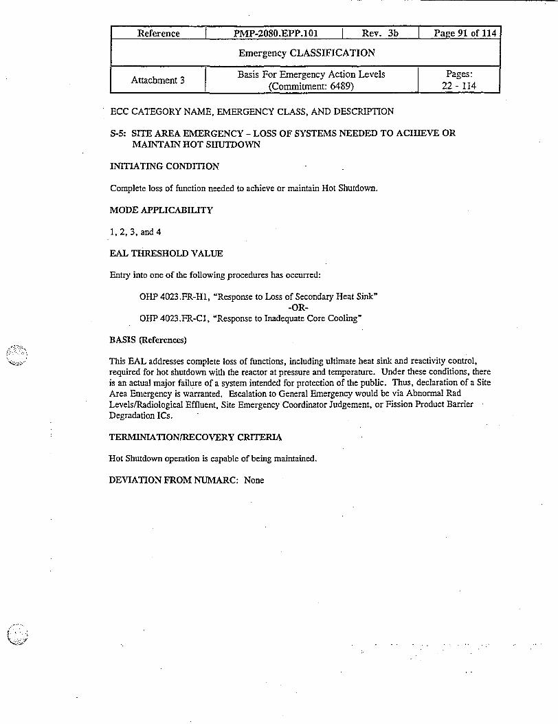
ECC CATEGORY NAME, EMERGENCY CLASS, AND DESCRIPTION
S-5: SITE AREA EMERGENCY - LOSS OF SYSTEMS NEEDED TO ACHIEVE ORMAINTAIN HOT SHUTDOWN
INITIATING CONDITION
Complete loss of function needed to achieve or maintain Hot Shutdown.
MODE APPLICABILITY
1, 2, 3, and 4
EAL THRESHOLD VALUE
Entry into one of the following procedures has occurred:
OHP 4023.FR-H1, "Response to Loss of Secondary Heat Sink"-OR-
OHP 4023.FR-C1, Response to Inadequate Core Cooling"
BASIS (References)
This EAL addresses complete loss of functions, including ultimate heat sink and reactivity control,required for hot shutdown with the reactor at pressure and temperature. Under these conditions, thereis an actual major failure of a system intended for protection of the public. Thus, declaration of a SiteArea Emergency is warranted. Escalation to General Emergency would be via Abnormal RadLevels/Radiological Effluent, Site Emergency Coordinator Judgement, or Fission Product BarrierDegradation ICs.
TERMINIATIONIRECOVERY CRITERIA
Hot Shutdown operation is capable of being maintained.
DEVIATION FROM NUMARC: None
Reference i PMP-2080.EPP.101 I Rev. 3b I Page 91 of 114
Emergency CLASSIFICATION
Attachment 3 Basis For Emergency Action Levels Pages:I (Commiitment: 6489) 22 -114

ECC CATEGORY NAME, EMERGENCY CLASS, AND DESCRIPTION
S-6: UNUSUAL EVENT - LOSS OF ALARMS OR INDICATION
INITIATING CONDITION
Unplanned loss of safety system annunciators and/or indications in the Control Room for greater than15 minutes.
MODE APPLICABILITY
1,2,3, and4
EAL THRESHOLD VALUE
1. Loss of one of the following:
a. Loss of one or more safety system annunciator panels in a unit for > 15 minutes:
* Panels 104-114, 119, 120 (Unit 1)* Panels 204-214, 219, 220 (Unit 2)
b. A known loss of indications associated with the following parameters for > 15 minutes(See Attachment 2):
* Neutron Flux - Gammametrics)* Reactor Coolant Pressure (Wide Range)* Reactor Coolant Outlet Temperature Thot (Wide Range)* Reactor Coolant Outlet Temperature Tcold (Wide Range)* Incore Thermocouples (Core Exit Thermocouples)* Reactor Coolant System Subcooling Margin Monitor* Reactor Coolant Inventory System (Reactor Vessel Level Indication)* Pressurizer Water Level* Charging Pump Flow* Charging Pump Breaker Status* Safety Injection Pump Breaker Status* Safety Injection Flow* Refueling Water Storage Tank Water Level* Containment Water Level* Containment Pressure (Wide Range)* Containrent Pressure (Narrow Range)* Containmnent Hydrogen Monitoring* Containment Isolation Valve Position Monitoring* Containrment Area Radiation Monitors (High Range)* Steam Line Pressure
Reference PMP-2080.EPP.101 I Rev. 3b I Pave 92 of 114
Emergency CLASSIFICATION
Attachment 3 Basis For Emergency Action Levels Pages:(Commnitment: 6489) 22 - 114
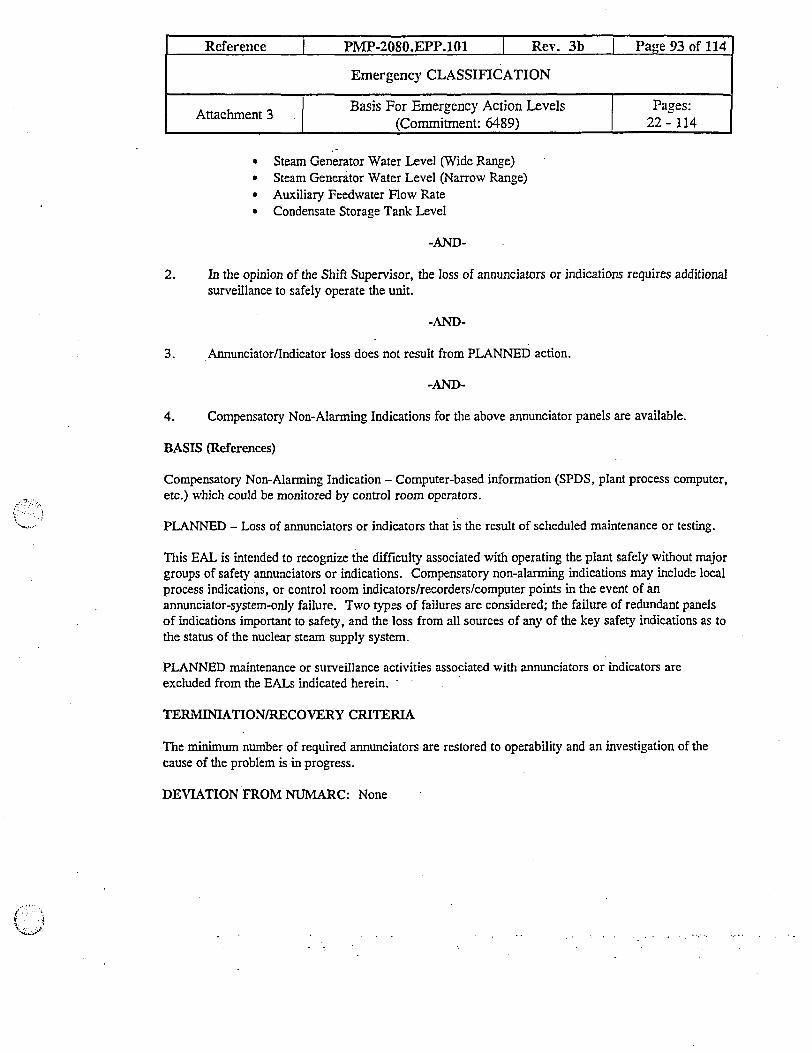
* Steam Generator Water Level (Wide Range)* Steam Generator Water Level (Narrow Range)* Auxiliary Feedwater Flow Rate* Condensate Storage Tank Level
-AND-
2. In the opinion of the Shift Supervisor, the loss of annunciators or indications requires additionalsurveillance to safely operate the unit.
-AND-
3. Annunciator/Indicator loss does not result from PLANNED action.
-AND-
4. Compensatory Non-Alarming Indications for the above annunciator panels are available.
BASIS (References)
Compensatory Non-Alarning Indication - Computer-based information (SPDS, plant process computer,etc.) which could be monitored by control room operators.
PLANNED - Loss of annunciators or indicators that is the result of scheduled maintenance or testing.
This EAL is intended to recognize the difficulty associated with operating the plant safely without majorgroups of safety annunciators or indications. Compensatory non-alarming indications may include localprocess indications, or control room indicators/recorders/computer points in the event of anannunciator-system-only failure. Two types of failures are considered; the failure of redundant panelsof indications important to safety, and the loss from all sources of any of the key safety indications as tothe status of the nuclear steam supply system.
PLANNED maintenance or surveillance activities associated with annunciators or indicators areexcluded from the EALs indicated herein.
TERMINIATION/RECOVERY CRITERIA
The minimum number of required annunciators are restored to operability and an investigation of thecause of the problem is in progress.
DEVIATION FROM NUMARC: None
Reference I PMP-2080.EPP.101 I Rev. 3b I Page 93 of 114
Emergency CLASSIFICATION IAttachment 3 Basis For Emergency Action Leve] Pages:L ~ ~ ~~1(Commitment: 6489) 22 - 114

ECC CATEGORY NAME, EMERGENCY CLASS, AND DESCRIPTION
S-6: ALERT - LOSS OF ALARMS OR INDICATION
INITIATING CONDITION
Unplanned loss of most or all safety system annunciators or indications in the Control Room with either(1) a significant transient in progress, or (2) compensatory non-alarming indicators are unavailable.
MODE APPLICABILITY
1, 2, 3, and 4
EAL THRESHOLD VIALUE
1. Loss of one of the following:
a. Loss of one or more safety system annunciator panels in a unit for > 15 mninutes:
* Panels 104-114, 119, 120 (Unit l)* Panels 204-214, 219, 220 (Unit 2)
b. A known loss of indications associated with the following parameters for > 15 minutes(See Attachment 2):
* Neutron Flux - Gammametrics)* Reactor Coolant Pressure (Wide Range).-* Reactor Coolant Outlet Temperature Thot (Wide Range)* Reactor Coolant Outlet Temperature Tcold (Wide Range)* Incore Thermocouples (Core Exit Thermocouples)* Reactor Coolant System Subcooling Margin Monitor* Reactor Coolant Inventory System (Reactor Vessel Level Indication)* Pressurizer Water Level* Charging Pump Flow* Charging Pump Breaker Status* Safety Injection Pump Breaker Status* Safety Injection Flow* Refueling Water Storage Tank Water Level* Containment Water Level* Containment Pressure (Wide Range)• Containment Pressure (Narrow Range)* Contaimnent Hydrogen Monitoring* Containment Isolation Valve Position Monitoring* Containment Area Radiation Monitors (High Range)* Steam Line Pressure
Reference I PMP-2080.EPP.101 I Rev. 3b I Paoe 94 of 114
Emergency CLASSIFICATION
~ Attachment 3 j Basis For Emergency Action Levels PagesI ~ ~ ~ ~I.(Commitment: 6489) 1 22 - 114
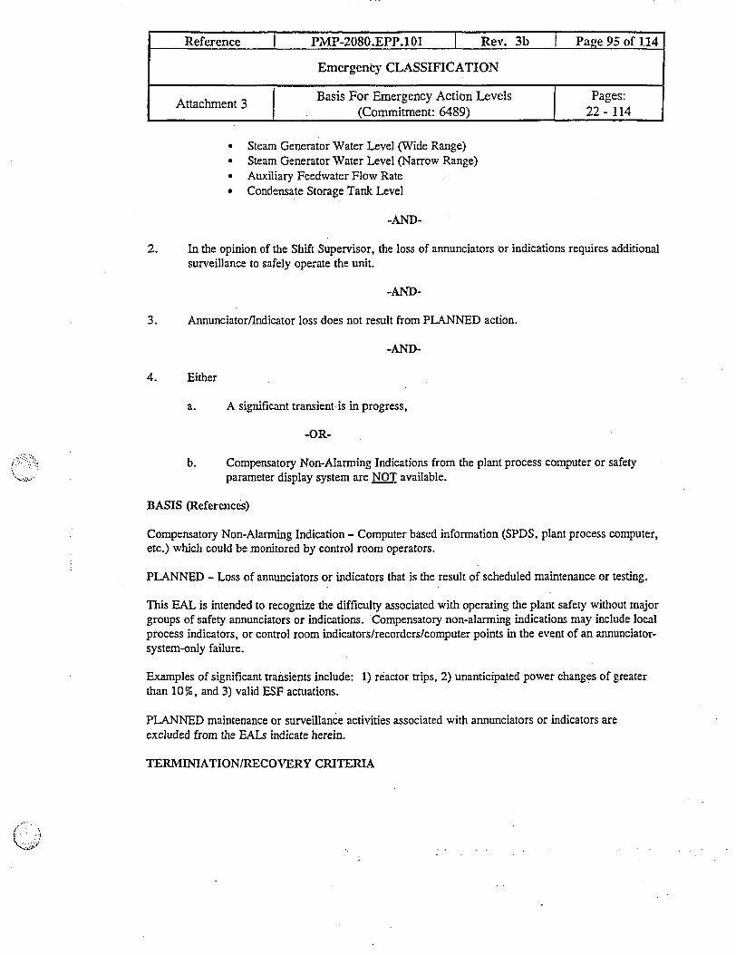
* Steam Generator Water Level (Wide Range)* Steam Generator Water Level (Narrow Range)* Auxiliary Feedwater Flow Rate* Condensate Storage Tank Level
-AND-
2. In the opinion of the Shift Supervisor, the loss of annunciators or indications requires additionalsurveillance to safely operate the unit.
-AND-
3. Annunciator/Indicator loss does not result from PLANNED action.
-AND-
4. Either
a. A significant transient-is in progress,
-OR-
b. Compensatory Non-Alarming Indications from the plant process computer or safetyparameter display system are NOT available.
BASIS (References)
Compensatory Non-Alarming Indication - Computer based inforrnation (SPDS, plant process computer,etc.) which could be monitored by control room operators.
PLANNED - Loss of annunciators or indicators that is the result of scheduled maintenance or testing.
This EAL is intended to recognize the difficulty associated with operating the plant safety without majorgroups of safety annunciators or indications. Compensatory non-alarming indications may include localprocess indicators, or control room indicators/recorders/computer points in the event of an annunciator-system-only failure.
Examples of significant transients include: 1) reactor trips, 2) unanticipated power changes of greaterthan 10%, and 3) valid ESF actuations.
PLANNED maintenance or surveillance activities associated with annunciators or indicators areexcluded from the EALs indicate herein.
TERMINIATION/RECOVERY CRITERIA
Reference I PMP-2080.EPP.101 I Rev. 3b I Page 95 of 114
Emergency CLASSIFICATION
Attachment 3 Basis For Emergency Action Levels Pages:I (Commitment: 6489) 22 - 114

Reference I PMP-2080.EPP.101 I Rev. 3b I Page 96 of 114
Emergency CLASSIFICATION
i Attachment 3 Basis For Emergency Action Levels Pages:I[ (Commitment: 6489) 1 22 - 114
The miniimum number of required annunciators is restored to operabilih,r and an investigation of thecause of the problem is in progress.
DEVIATION FROM NUMARC: None

ECC CATEGORY NAME, EMERGENCY CLASS, AND DESCRIPTION
S-6: SITE AREA EMERGENCY - LOSS OF ALARMS OR INDICATION
INITIATING CONDITION
Inability to monitor a significant transient in progress.
MODE APPLICABILITY
1, 2, 3, and 4
EAL THRESHOLD VALULE
Loss of one of the following:
1. Loss of one or more safety system annunciator panels in a unit for > 15 minutes:
* Panels 104-114, 119, 120 (Unit 1)* Panels 204-214, 219, 220 (Unit 2)
2. A known loss of indications associated with the following parameters (See Attachment 2) for >15 minutes which in the opinion of the Shift Supervisor significantly affects the ability to safelyoperate or shutdown the unit.
* Neutron Flux - Gammametrics)* Reactor Coolant Pressure (Wide Range)* Reactor Coolant Outlet Temperature Thot (Wide Range)* Reactor Coolant Outlet Temperature Tcold (Wide Range)* Incore Thermocouples (Core Exit Thermocouples)* Reactor Coolant System Subcooling Margin Monitor* Reactor Coolant Inventory System (Reactor Vessel Level Indication)* Pressurizer Water Level* Charging Pump Flow* Charging Pump Breaker Status* Safety Injection Pump Breaker Status* Safety Injection Flow* Refueling Water Storage Tank Water Level* Containment Water Level* Containment Pressure (Wide Range)* Containment Pressure (Narrow Range)* Containment Hydrogen Monitoring* Containment Isolation Valve Position Monitoring* Containment Area Radiation Monitors (High Range)* Steam Line Pressure
Reference I PMP-2080.EPP.101 Rev. 3b Page 97 of 114_
Emergency CLASSIFICATION
Attachment 3 Basis For Emergency Action Levels Pages:Attachmen 3 |(Commitment: 6489) | 22 - 114

* Steam Generator Water Level (Wide Range)* Steam Generator Water Level (Narrow Range)* Auxiliary Feedwater Flow Rate* Condensate Storage Tank Level
-AND-
3. Compensatory Non-Alarming Indications from the plant process computer or safety parameterdisplay system are NOT available.
-AND-
4. A significant transient is in progress.
BASIS (References)
Compensatory Non-Alarming Indication - Computer based information (SPDS, plant process computer,etc.) which could be monitored by control room operators.
This EAL is intended to recognize the difficulty associated with operating the plant safely without majorgroups of safety annunciators or indications. Compensatory non-alarming indications may include localprocess indications, or control room indicators/recorders/computer points in the event of anannunciator-system-only failure. A significant transient is not intended to be strictly defined, however,the following examples are provided: 1) reactor trips; 2) unanticipated power changes of > 10%, and 3)valid ESF actuations. NUREG 0737 instruments are included in this EAL to provide a redundantmeans for monitoring the plant should annunicators become unavailable. To prevent overclassifying anevent to a Site Area Emergency, Shfit Supervisor discretion has been provided for. This allows theShift Supervisor to decide if the specific indications which are unavailable are needed to monitor thetransient in progress.
TERMINIATION/RECOVERY CRITERIA
Transient is terminated and ability to monitor plant parameters is restored.
DEVIATION FROM NUMARC: None
Reference I PMP-2080.EPP.101 | Rev. 3b Page 98 of 114
Emergency CLASSIFICATION
Attachment 3 | Basis For Emergency Action Levels Pages:Attachment 3 (Commitment: 6489) 1 22 - 114
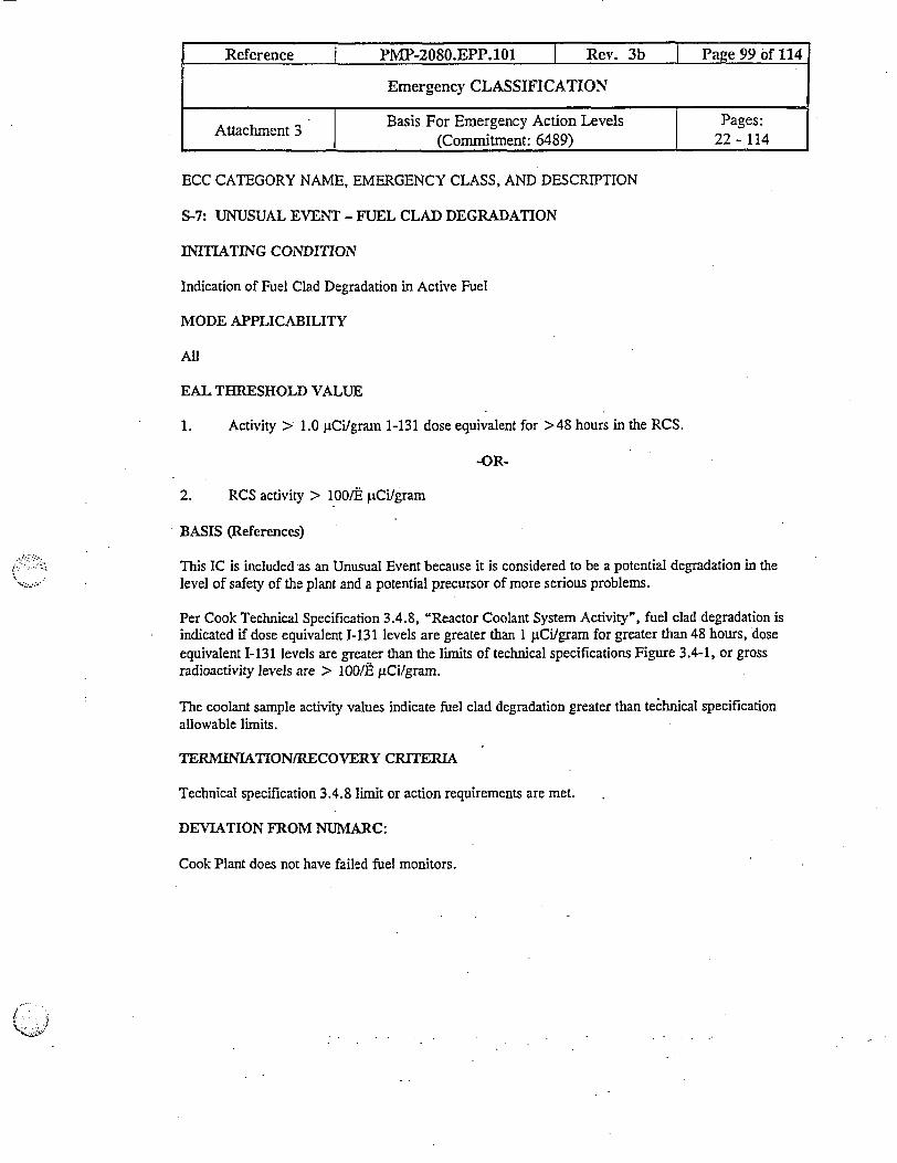
ECC CATEGORY NAME, EMERGENCY CLASS, AND DESCRIPTION
S-7: UNUSUAL EVENT - FUEL CLAD DEGRADATION
IITIATING CONDITION
Indication of Fuel Clad Degradation in Active Fuel
MODE APPLICABILITY
All
EAL THRESHOLD VALUE
1. Activity > 1.0 plCilgram 1-131 dose equivalent for >48 hours in the RCS.
-OR-
2. RCS activity > 1001E pCi/gram
BASIS (References)
This IC is included as an Unusual Event because it is considered to be a potential degradation in thelevel of safety of the plant and a potential precursor of more serious problems.
Per Cook Technical Specification 3.4.8, "Reactor Coolant System Activity", fuel clad degradation isindicated if dose equivalent I-131 levels are greater than 1 pCi/gram for greater than 48 hours, doseequivalent I-131 levels are greater than the limits of technical specifications Figure 3.4-1, or grossradioactivity levels are > 100/E liCiIgram.
The coolant sample activity values indicate fuel clad degradation greater than technical specificationallowable limits.
TERMINIATION/RECOVERY CRITERIA
Technical specification 3.4.8 limit or action requirements are met.
DEVIATION FROM NUMARC:
Cook Plant does not have failed fuel monitors.
Reference I PMP-2080.EPP.101 Rev. 3b Page 99 of 114
Emergency CLASSIFICATION
Attachment 3 - Basis For Emergency Action Levels Pages:(Commitment: 6489) | 22 - 114

ECC CATEGORY NAME, EMERGENCY CLASS, AND DESCRIPTION
S-8: UNUSUAL EVENT - ESCESSIVE RCS LEAKAGE
INITIATING CONDITION
Reactor Coolant System Leakage
MODE APPLICABILITY
1,2,3,4
EAL THRESHOLD VALUE
Reactor coolant system leakage exceeds one of the following values:
1. Pressure boundary leakage > 10 gpm-OR-
2. SG tube leakage > 10 gpm-OR-
3. Identified leakage > 25 gpm-OR-
4. Unidentified leakage > 10 gpm
BASIS (References)
This IC is included as an Unusual Event because it may be a precursor of more serious conditions andas a result, is considered to be a potential degradation of the level of safety of the plant. The 10 gpmvalue for unidentified or pressure boundary leakage was selected because it is observable with normalcontrol room indications. Lesser values must generally be determined through time-consumingsurveillance test (e.g., mass balances). The generic EAL for identified leakage is set at a higher value(25 gpm) due to the lesser significance of identified leakage in comparison to unidentified or pressureboundary leakage.
Only operating modes in which there is fuel in the reactor coolant system and the system is pressurizedare specified.
TERMINIATION/RECOVERY CRITERIA
Leakage is isolated OR Cold Shutdown (Mode 5) is established.
DEVIATION FROM NUMARC: None
Reference P1IP-2080.EPP.101 | Rev. 3b I Page 100 of 114
Emergency CLASSIFICATION
Attachment 3 Basis For Emergency Action Levels Pages:(Commitment: 6489) 1 22 - 114
ECC CATEGORY NAME, EMERGENCY CLASS, AND DESCRIPTION
S-9: UNUSUAL EVENT - TECHNICAL SPECIFICATION TIME LIMIT EXPIRED
INITIATING CONDITION
Inability to reach required shutdown within Technical Specification time limits.
MODE APPLICABILITY
1,2,3,4
EAL THRESHOLD VALUE
Unit is NOT placed in required MODE within Technical Specification LCO action time limit.
BASIS (References)
Limiting Conditions of Operation LCOs) require the plant to be brought to a required shutdown modewhen the technical specification required configuration camot be restored. Depending on thecircumstances, this may or may not be an emergency or precursor to a more severe condition. In any'case, the initiation of plant shutdown required by the site technical specification requires a four hourreport under 10 CFR 50.72 (b) Non-emergency events. The plant is within its safety envelope whenbeing shutdown within the allowable action statement time in the technical specifications. Anirnmediate Notification of an Unusual Event is required when the plant is not brought to the requiredoperating mode within the allowable action statement time in the technical specifications. Declarationof an Unusual Event is based on the time at which the LCO-specified action statement time periodelapses under the site technical specifications and is not related to how long a condition may haveexisted. Other required technical specification shutdowns that involve precursors to more seriousevents are addressed by other System Malfunction, Hazards, or Fission Product Barrier DegradationICs.
TERMIATION/RECOVERY CRITERIA
Unit has reached cold shutdown (Mode 5) or other mode as specified in the limiting condition foroperation action statement.
-OR-
Unit has been placed in a Mode where the LCO no longer applies.
DEVIATION FROM NUMARC: None
Reference I PMP-2080.EPP.101 I Rev. 3b Page 101 of 114
Emergency CLASSIFICATION
Attachment 3 Basis For Emergency Action Levels Pages:(Comnitment: 6489) 22 - 114
ECC CATEGORY NAME, EMERGENCY CLASS, AND DESCRIPTION
S-10: UNUSUAL EVENT - LOSS OF COMMUNICATION SYSTEMS
INITIATING CONDITION
Unplanned loss of all onsite or offsite communications.
MODE APPLICABILITY
1, 2, 3, 4
EAL THRESHOLD VALUE
1. UNPLANNED loss of ALL onsite electronic communication capabilities:
- TelephonePage SystemRadios
-OR-
2. UNPLANNED loss of ALL offsite electronic cormnunication capabilities:
Telephone (offsite)Microwave transmissionNRC phoneState Police/Sheriff Department Emergency Radios
BASIS (References)
UNPLANNED - The loss of communication js not a result o planned testing, maintenance orsurveillance activities.
The purpose of this IC and its associated generic EALs is to recognize a loss of coununicationscapability that either defeats the plant operations staff ability to perform routine tasks or the ability tocommunicate problems with offsite authorities. The loss of offsite communications capability isexpected to be significantly more comprehensive than that addressed by 10 CFR 50.72. The loss ofoffsite communications capability is applicable when no direct means is available to communicate withor makes notifications to the load dispatcher or state and federal authorities.
TERMINIATION/RECOVERY CRITERIA
At least one form of onsite and offsite communications has been established.
DEVIATION FROM NUMARC: None
Reference I PMP-2080.EPP.101 I Rev. 3b I Panye 102 of 114
Emergency CLASSIFICATION
Basis For Emergency Action Levels Pages:(Counitment: 6489) 22 - 114

ECC CATEGORY NAME, EMERGENCY CLASS, AND DESCRIPTION
C-3 UNUSUAL EVENT - LOSS OF AC POWER ALL OFFSITE POWER TO ESSENTIALBUSES FOR GREATER THAN 15 MINUTES
INITIATING CONDITION
Loss of all offsite power to essential buses for greater than 15 minutes.
MODE APPLICABILITY
5, 6
EAL THRESHOLD VALUE
1. ALL of the following OFFSITE power sources indicated by the following list of transfonnerare LOST to the T-buses for > 15 minutes.
a. Normal Auxiliary Power Source (Auxiliary Transformer)
* TR 1AB /TR 2AB* TR ICD /TR 2CD
b. Preferred Offsite Power Sources (Reserve Transformer)
* TR 101AB /TR 201AB* TR 11CD TR 201CD
c. Emergency Offsite Power Source (69Kv Transformer)
* T-12-EP-1
-AND-.
2. At lease one diesel generator per unit is supplying power to the emergency buses.
BASIS (References)
Prolonged loss of AC power reduces required redundancy and potentially degrades the level of safety ofthe plant by rendering the plant more vulnerable to a complete Loss of AC Power (Station Blackout).Fifteen minutes was selected as a threshold to exclude transient or momentary power losses.
Offsite power can be supplied via the 69Kv emergency feed lines or from the switchyard via the reservetransformers. During outages, switchyard power may be supplied via the normal transformers aligned
Reference I PMP-2080.EPP.101 Rev. 3b Paoe 103 of 114
Emergency CLASSIFICATION
Attachment 3 | Basis For Emergency Action Levels Pages:Attachmen 3 1(Commitment: 6489) 1 22 - 114

for "backfeed". During outages, the backfeed alignment should be considered equivalent to reservefeed for the purpose of emergency classification level determinations.
TERMINIATION/RECOVERY CRITERIA
A reliable power supply to ESF buses from offsite sources is re-established.
DEVIATION FROM NUMARC: None
Reference I PMP-2080.EPP.101 | Rev. 3b I Page 104 of 114
Emergency CLASSIFICATION
Attachmnent 3 | Basis For Emergency Action Levels Pages:Attacrnen 3 (Commitment: 6489) L 22 - 114

ECC CATEGORY NAME, EMERGENCY CLASS, AND DESCRIPTION
C-3 ALERT - LOSS OF AC POWER ALL OFFSITE POWER AND LOSS OF ALL ONSITEAC POWER TO ESSENTLAL BUSES
INITATING CONDITION
Loss of ALL offsite power and loss of ALL onsite AC power to essential buses.
MODE APPLICABILITY
5, 6 or defueled
EAL THRESHOLD VALUE
1. Loss of both of the following T-buses for > 15 ninutes when fuel is in the reactor.
a. T1lA, T11D (Unit 1)
-OR-
b. T21A, T21D (Unit 2)
2. Loss of power to all the following buses when defueled T11A, TlD, T21A, T21D
BASIS (References)
In Modes 5 and 6, loss of all AC power compromises all plant safety systems requiring electric powerincluding RHR, ECCS, Containment Heat Removal, Spent Fuel Heat Removal, and ESW. When incold shutdown, refueling, or defueled mode the event can be classified as an Alert, because of thesignificantly reduced decay heat, lower temperature and pressure. An Alert is declared in these modesdue to the less severe threat to the protection of the health and safety of the public because of the muchlonger time available to restore power and decay he'at removal systems. Fifteen minutes was'selected asa threshold to exclude transient or momentary power losses. Escalating to Site Area Emergency, ifappropriate, is by Abnormal Rad Levels/Radiological Effluent, or SEC Judgement ICs.
When a unit is defueled, power from an essential bus on either unit will be sufficient to provideemergency power to required plant safety systems.
TERMINIATION/RECOVERY CRITERIA
Restore power to at least one T-bus.
DEVIATION FROM NUMARC:
Reference I PMP-2080.EPP.101 I Rev. 3b I Page 103 of 114
Emergency CLASSIFICATION
Attachment 3 Basis For Emergency Action Levels Pages:I (Commitment: 6489) 22 - 14
Reference I PMP-2080.EPP.101 I Rev. 3b I Page 106 of 114
Emergency CLASSIFICATION
Attachment 3 Basis For Emergency Action Levels Pages:I (Commitment: 6489) _ 22 - 114
This EAL is specified by loss of essential pump buses rather than loss of transformers and emergencygenerators.
ECC CATEGORY NAME, EMERGENCY CLASS, AND DESCRIPTION
C4: ALERT - INABILITY TO MAINTAIN A UNIT IN COLD SHUTDOWN
INITIATING CONDITION
Inability to maintain plant in Cold Shutdown.
MODE APPLICABILITY
5, 6
EAL THRESHOLD VALUE
1. Loss of shutdown cooling as evidenced by entry into OHP 4022.017.001, "Loss of RHRCooling."
-AND-
2. Temperature increase that either
a. exceeds Technical Specification cold shutdown limit of 200°F
-OR-
b. results in an UNCONTROLLED increase in RCS temperature rise approaching the coldshutdown techriical specification limit of 200°F.
BASIS (References)
UNCONTROLLED -. means a temperature increase that is not the result of a planned evolution. It isincluded to preclude the declaration of an emergency for circumstances where decay head removal isintentionally removed from service and is controlled within the requirements of the technical.specifications.
The threshold value indicates a substantial degradation in the level of safety of the plant by indicating apotential complete loss of the ability to removal decay heat in the Cold Shutdown and Refueling modes.NRC concerns expressed in Generic Letter 88-17, "Loss of Decay Heat Removal" are the basis for thethreshold value as an anticipatory sequence leading to core uncovery and clad damage.
The threshold related to an uncontrolled temperature rise is necessary to preserve the anticipatoryphilosophy of NUREG-0654 for events starting from temperatures much lower than 200°F. Theinability to reach cold shutdown is to include instances where decay heat removal capability is lost priorto reaching the cold shutdown mode.
Refserence I PMP-2080.EPP.101 I Rev. 3b I Pa e 107 of 114
Reerc Emergency CLASSIFICATION
Attachment 3 | Basis For Emergency Action Levels Pages:Attachment (Commitment: 6489) 1 22 - 114

TElRMINIATION/RECOVERY CRITERIA
Cold shutdown conditions have been established and can be maintained.
DEVIATION FROM NUMARC
None.
Reference I PMP-2080.EPP.101 i Rev. 3b I Page 108 of 114
Emergency CLASSIFICATION
Attachment 3 Basis For Emergency Action Levels Pages:I c -I (Commitment: 6489) e 22-- 114

Reference PMP-2080.EPP.101 Rev. 3b Page 109 of 114
Emergencv CLASSIFICATION
Attachment 3 | Basis For Emergency Action Levels | Pages:(Commitment: 6489) 22 -114
ECC CATEGORY NAME, EMERGENCY CLASS, AND DESCRIPTION
C-4: SITE AREA EMERGENCY - INABILITY TO MAINTAIN A UNIT IN COLDSHUTDOWN
INITIATING CONDITION
LOSS of water level in the reactor vessel that has or will uncover fuel in the reactor vessel.
MODE APPLICABILITY
5, 6
EAL THRESHOLD VALUE
Loss of reactor vessel water level as indicated by:
1. LOSS of shutdown cooling as evidenced by entry into OHP 4022.017.001, "Loss of RHRCooling."
-AND-2. Core uncovery as indicated by:
a. RVLIS NR < 46% - 0 RCPs-OR-
b. Reactor Vessel Water Level < 614'
BASIS (References)
LOSS - Inability to restore RHR operability (e.g., restart the RHR pumps) when required.
The threshold values indicate that severe core damage can occur and RCS integrity may not be assuredand thus indicate failures of functiohs needed for the protection of the public.
These conditions address prolonged boiling as a result of loss of decay heat remoVal.
TERMINIATION/RECOVERY CRITERIA
Restoration of lost core inventory is in progress, level is above the top of the active fuel, and decay heatremoval capability has been restored.
DEVIATION FROM NUMARC:
None.

ECC CATEGORY NAME, EMERGENCY CLASS, AND DESCRIPTION
C-5: UNUSUAL EVENT - FUEL CLAD DEGRADATION
INITIATING CONDITION
Fuel clad degradation.
MODE APPLICABILITY
5, 6
EAL THRESHOLD VALUE -
1. (Site-specific) radiation monitor readings indicating fuel clad degradation greater than TechnicalSpecification allowable limits.
OR
2. RCS sample activity value indicating fuel clad degradation greater than Technical Specificationallowable limits.
BASIS (References)
This IC is included as a UE because it is considered to be a potential degradation in the level of safetyof the plant and a potential precursor of more serious problems. EAL #1 addresses site-specificradiation monitor readings that provide indication of fuel clad integrity. EAL #2 addresses coolantsamples exceeding coolant technical specification for iodine spike.
TERMINIATION/RECOVERY CRITERIA
DEVIATION FROM NUMARC:
Cook Plant does not have failed fuel monitors.
Reference PMP-2080.EPP.101 I Rev. 3b I Page 110 of 114
Emergency CLASSIFICATION
i Attachment 3 Basis For Emergency Action Levels Pages:I (Commitment: 6489) 22 - 114
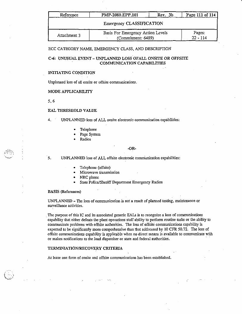
ECC CATEGORY NAME, EMERGENCY CLASS, AND DESCRIPTION
C-6: UNUSUAL EVENT - UNPLANNED LOSS OFALL ONSITE OR OFFSITECOMMUNICATION CAPABILITIES
INITIATING CONDITION
Unplanned loss of all onsite or offsite communications.
MODE APPLICABILITY
5, 6
EAL THRESHOLD VALUE
4. UNPLANNED loss of ALL onsite electronic communication capabilities:
* Telephone* Page System* Radios
-OR-
5. UNPLANNED loss of ALL offsite electronic communication capabilities:
* Telephone (offsite)* Microwave transmission* NRC phone* State Police/Sheriff Department Emergency Radios
BASIS (References)
UNPLANNED - The loss of communication is not a result of planned testing, maintenance orsurveillance activities.
The purpose of this IC and its associated generic EALs is to recognize a loss of communicationscapability that either defeats the plant operations staff ability to perform routine tasks or the ability tocommunicate problems with offsite authorities. The loss of offsite communications capability isexpected to be significantly more comprehensive than that addressed by 10 CFR 50.72. The loss ofoffsite communications capability is applicable when no direct means is available to communicate withor makes notifications to the load dispatcher or state and federal authorities.
TERMINIATION/RECOVERY CRITERIA
At lease one form of onsite and offsite communications has been established.
Reference PMP-2080.EPP.101 I Rev. 3b Page 111 of 114
Emergency CLASSIFICATION
Attachment 3 Basis For Emergency Action Levels Pages:(Commitnent: 6489) 22 - 114

Reference I PMP-2080.EPP.101 I Rev. 3b I Page 112 of 114
Emergency CLASSIFICATION
Attachment 3 | Basis For Emergency Action Levels Pages:l (Commitment: 6489) 1 22 - 114
DEVIATION FROM NUMARC: None

ECC CATEGORY NAME, EMERGENCY CLASS, AND DESCRIPTION
C-7 UNTUSUAL EVENT - UNPLANNED LOSS OF DC POWER FOR GREATER THAN 15MINUTES
INITIATING CONDITION
Unplanned loss of required DC power during cold shutdown or refueling mode for greater than 15minutes.
MODE APPLICABILITY
5, 6
EAL THRESHOLD VALUE
UNPLANNED loss of 250 volt DC buses AB AND CD as indicated by bus voltage < 220 volts DCfor greater than 15 minutes.
BASIS (References)
The purpose of this IC and its associated generic EAL is to recognize a loss of DC powercompromising the ability to monitor and control the removal of decay heat during Cold Shutdown orRefueling operations. This EAL is intended to be anticipatory in as much as the operating crew maynot have necessary indication and control equipment needed to respond to the loss.
The threshold value was chosen to recognize a loss of DC power at a voltage level low enough to beindicative of a severe control system problem. This value is high enough to provide reasonableassurance that the 250 volt batteries will last at least 15 minutes prior to reaching a designed minimumvoltage of 210 volts.
UNPLANNED is included in this IC and EAL to preclude-the declaration of an emergency as a resultof planned maintenance activities. Routinely, plants will perform maintenance on a train related basisduring shutdown periods. It is intended that the loss of the operating (operable) train is to'beconsidered. If this loss results in the inability to maintain cold shutdown, the escalation to Alert will beper C-4, "Inability to Maintain Plant in Cold Shutdown with Irradiated Fuel in the Reactor Vessel."
Plant Specific Information
DC systems are not shared between Cook Units 1 and 2.
Reference I PMP-2080.EPP.101 I Rev. 3b I Page 113 of 114
Emergency CLASSIFICATION
Attachmnent 3 | Basis For Emergency Action Levels Pages:(Commitment: 6489) 22 - 114

The Cook 250 VDC system includes three major battery groups for each unit.
* Station or Plant Battery Train A ( supplies 250 Bus CD)• Station or Plant Battery Train B (supplies 250 Bus AB)* N Train Battery
The N train battery supplies TDAFW control bus and the AMSAC inverter. Since these are backupsystems, this bus is not included in this EAL.
The above symptoms include equipment which may be used to monitor and control the removal ofdecay heat during Cold Shutdown or Refieling operations (i.e., annunciators, PZ PORVs, steamdumps, SG PORVs).
TERMINIATION/RECOVERY CRITERIA
Power is restored to at least one 250 volt DC bus and an investigation as to the cause is underway.
DEVIATION FROM NUMARC: None
Reference I PMP-2080.EPP.101 I Rev. 3b I Page 114 of 114
Emergency CLASSIFICATION
i Attachment 3 Basis For Emergency Action Levels Pages:I ~~~~~~~~(Comimitment: 6489) 1 22 - 114

REVIEW AND APPROVAL TRACKING FORM
LI- UCL�tJUF� iniormation: --�--=� �-- - -�-�--�, -, +, - _ t _ t __-_' $l- '_ - ' ,
Number: PMP-2080-EPP-107 _ Rev. 17 Change: 0
Title: Notiication
Category (Sel&ct .Oe6 & vmnK ,-
E Correction (Full Procedure) 3 Change (Full Procedure) with Review of Change Onlyl Correction (Page Substitution) El Change (Page Substitution) with Review of Change Only
El Cancellation [l New Procedure or Change with Full ReviewEl Superseded (list superseding procedures):
:. - �#q MP�p���-' ax
'v,Ass"iated Coiif' a ex 6n f q_ij�a_c-Change Driver/CDT Trackinp No(s): Rl N/A
Required Reylewss. : .'-lCross-Discipline Reviews:El Chemistry 0 TrainingEl Maintenance El Work ControlEUNDM _0 Operations ElE PAtPV EEl Reg Affairs EE RP E None Required
3 Cognizant Org Review:
z Technical Review:
Programmatic Reviews:El ALARA
El Component EngineeringEl Design Engineering
El Emerg Oper Proc GrpEl EnvironmentalEl ISI/TST CoordinatorEl Performance Assurance
El Reactivity Mgmt TeamEl SPS (Safety & Health)E Surveillance SectionEl System Enginecring
ElEl
0 None Required
Concurrence: I. -
nl Ofne lVrpr'tnr rnnri1rrPnr' NIA Thntp- I IL__j _k" - - -I v l v s_a W ^^ I - Ia .-
aehck.a ~ -_r1P .;iG 3
Updated Revision Summary attached? 0 Yes10 CFR 50.59 Requirements complete? Tracking No.:_2003-0061-00 0 Yes E N/A
Implementation Plan developed? (Ref. Step 3.4.17) El Yes ON/APackage Complete: Wm Date: L_/Jq/ 03Approvas-_`1= M^PORC Review Required: 3 Yes El No Mtg. No.: 9
Administrative Hold Status: E Rel sed l Reissued Z N/A CR No.:_
Approval Authority Review/Approval: . *• __ Date: 2 124 103
Expiration Date/Ending Activity // i N Effective Date: j28/ 0t
Periodic,Revie'w: :_ir ;s , =
r, &1
Periodic Pview condrcted? (Data Sheet 5
IFollow-up Actions: -- - -
Commitment Database update requested in accordance with PMP-7100-CMP-001?NDM notified of new records or changes to records that could affect record retention? l Yes O NA
EI Yes
Ii
> 'Tc- I r * + T rac ing ni5, - Not .Pait &CFi-
This form is derived from thc information in PMP-2010-PRC-002,
Procedure Correction, Change, and Review, Rev. 10, Data Sheet I, /Revicw and Approval Tracking Form. Page _ of
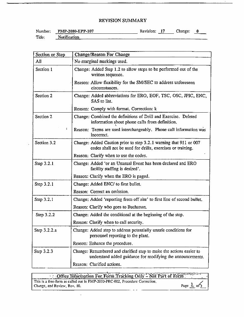
REVISION SIIARY
PMP-2080-EPP-107 Revision: 17 Change: 0Notification
Section or Step Change/Reason For Change
All No marginal markings used.
Section 1 Change: Added Step 1.2 to allow steps to be performed out of thewritten sequence.
Reason: Allow flexibility for the SM/SEC to address unforeseencircumstances.
Section 2 Change: Added abbreviations for ERO, EOF, TSC, OSC, JPIC, ENC,SAS to list.
Reason: Comply with format. Correction: k
Section 2 Change: Combined the definitions of Drill and Exercise. Deletedinformation about phone calls from definition.
Reason: Terms are used interchangeably. Phone call information wasincorrect.
Section 3.2 Change: Added Caution prior to step 3.2.1 warning that 911 or 007codes shall not be used for drills, exercises or training.
Reason: Clarify when to use the codes.
Step 3.2.1 Change: Added 'or an Unusual Event has been declared and EROfacility staffing is desired'.
Reason: Clarify when the ERO is paged.
Step 3.2.1 Change: Added ENC/ to first bullet.
Reason: Correct an omission.
Step 3.2.1 Change: Added 'reporting from off site' to first line of second bullet.
Reason: Clarify who goes to Buchanan.
Step 3.2.2 Change: Added the conditional at the beginning of the step.
Reason: Clarify when to call security.
Step 3.2.2.a Change: Added step to address potentially unsafe conditions forpersonnel reporting to the plant.
Reason: Enhance the procedure.
Step 3.2.3 Change: Renumbered and clarified step to make the actions easier tounderstand added guidance for modifying the announcements.
Reason: Clarified actions.
L____ o ffice Inf6rmation For Form .Tracking O N thPari of 1orm |
Page L _o |
Number:Title:
This is a free-Form as called out in PMP-2010-PRC-002, Procedure Correction,Change, and Review, Rev. 10.
..

REVISION SUMIARY
PMP-2080-EPP-107Notification
Revision: 17 Change: 0
Section or Step Change/Reason For Change
Step 3.2.3 Change: Deleted one of the 'Attention all personnel' phrases from eachof the announcements.
Reason: Eliminate redundancy.
Step 3.2.3.c Change: Added action to sound the Containnent Evacuation alarm.
Reason: To help ensure that all personnel on site are notified.
Step 3.2.5.a Change: Added 'a' before Nuclear Accident...
Reason: Grammar. Correction: a
Step 3.2.5.b Change: Added Note prior to first bullet and changed area code for the: county.
Reason- Clarifying information on what the MSP may do., Phonenumber change.
Step 3.2.5.b Change: Added conditional statement to the end of the second bullet toprovide phone directions.
Reason: The county EOC may not answer directly.
Step 3.2.5.d and f Change: Added 'the' before Nuclear Accident...
Reason: Grammar. Correction: a
Step 3.2.7 Change: Added 'or as directed by the MSP' to end of second bullet.
Reason: The MSP may provide other guidance for faxing.
Step 3.2.8 Change: Added new step 3.2.8. Renumbered remaining steps insection 3.2.
Reason: To clarify when the EMD-32a and EMD-32b forms must besent to the state.
Step 3.2.10 (old Change: Added 'or the PAR changes' to the first line.step 3.2.9) Reason: To include all requirements for notification.
Attachment I Change: Replaced EXERCISE, DRILL with the correct terms:
Step 1.1 Announced or Unannounced Drill.Reason: Correct terms.
Number:Title:
I i ,
- 4A.'.;A .. sg t--..Sr -
* '--ffice TIfforation or formy- ItTr- t.Prt - N Pt f F rm :.
This is a free-form as called out in PMP-2010-PRC-002, Procedure Correction,Change, and Revicw. Rev. 10. Page 1 of
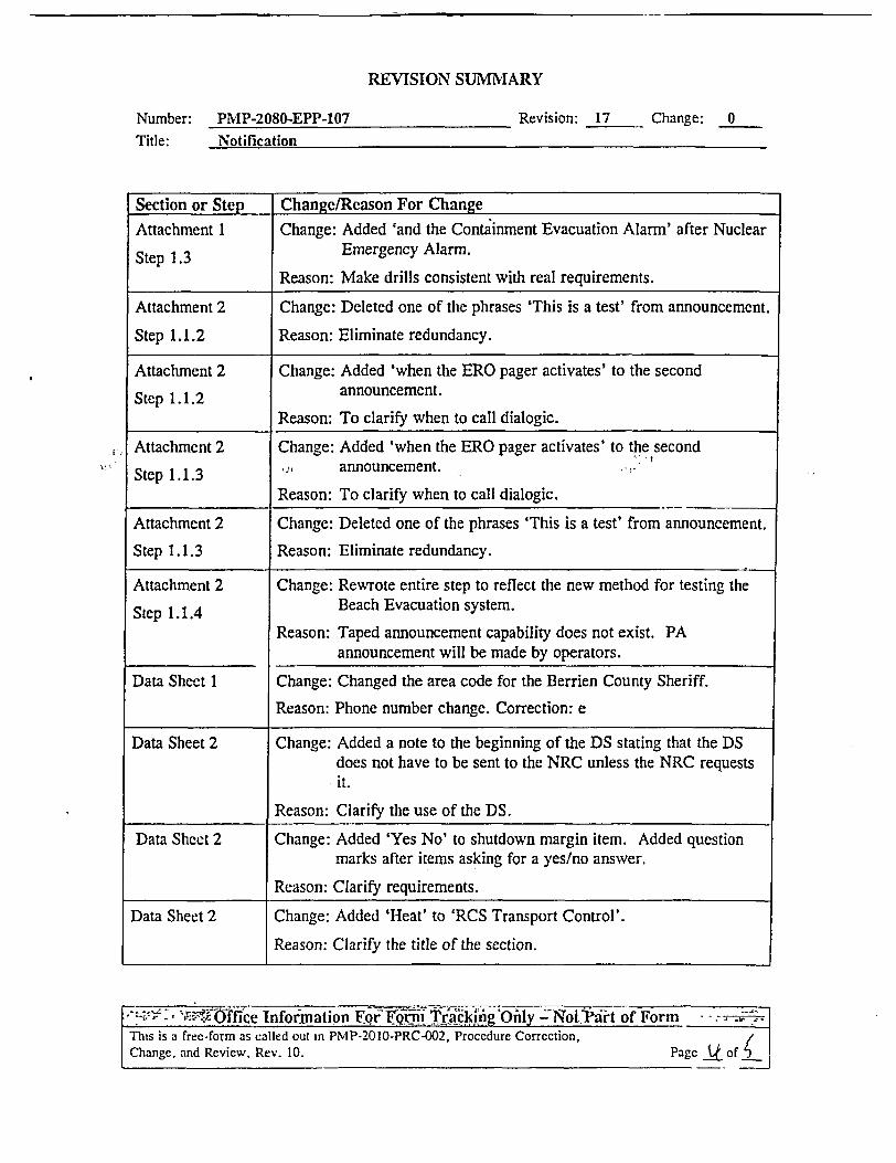
REVISION SUMMARY
Number: PMP-2080-EPP-107Title: Notification
Revision: 17 Change: 0
Section or Step Change/Reason For Change
Attachment 1 Change: Added 'and the Containment Evacuation Alarm' after Nuclear
Step 1.3 Emergency Alarm.Reason: Make drills consistent with real requirements.
Attachment 2 Change: Deleted one of the phrases 'This is a test' from announcement.
Step 1.1.2 Reason: Eliminate redundancy.
Attachment 2 Change: Added 'when the ERO pager activates' to the second
Step 1.1.2 announcement.Reason: To clarify when to call dialogic.
Attachment 2 Change: Added 'when the ERO pager activates' to the second
Step 1.1.3 , announcement.Reason: To clarify when to call dialogic.
Attachment 2 Change: Deleted one of the phrases 'This is a test' from announcement.
Step 1.1.3 Reason: Eliminate redundancy.
Attachment 2 Change: Rewrote entire step to reflect the new method for testing the
Step 1.1.4 Beach Evacuation system.Reason: Taped announcement capability does not exist. PA
announcement will be made by operators.
Data Sheet 1 Change: Changed the area code for the Berrien County Sheriff.
Reason: Phone number change. Correction: e
Data Sheet 2 Change: Added a note to the beginning of the DS stating that the DSdoes not have to be sent to the NRC unless the NRC requestsit.
Reason: Clarify the use of the DS.
Data Sheet 2 Change: Added 'Yes No' to shutdown margin item. Added questionmarks after items asking for a yes/no answer.
Reason: Clarify requirements.
Data Sheet 2 Change: Added 'Heat' to 'RCS Transport Control'.
Reason: Clarify the title of the section.
'- ' nOfice nfornation For 1 eigW diig Only =NoVPart of Form , - - -
Thts is a free-form as called out in PMP-2010-PRC-002, Procedure Correction,Change, and Review, Rev. 10. Page Q off

REVISION SUMiMIARY
Number: PiNIP-2080-EPP-107Title: Notification
Revision: 17 Change: 0
Section or Step Change/Reason For ChangeData Sheet 2 Change: Under 'RCS Heat Sink' changed 'Containment' to 'RCS'.
Reason: Containment is incorrect.
Data Sheet 2 Change: Added directions and blanks for checking equipment/methodsavailable based on plant conditions.
Reason: Clarify DS requirements.
-> : -~ 'Office nformation For Form Trink OxiW t Part f F iThis is a free-forTn as called out in PMP-2010-PRC-002, Procedure Correction, - 7Change, and Review, Rev. 10. Page < of j

ruc"trip | PIMP-2080-EPP-107 Rev. 17 Page I of 14
Notification
Reference Effective Date: 02,'28/03B. K. Molloy S. M. Partin Site Protective Services
Writer Owner Cognizant Organization
TABLE OF CONTENTS
1 PIURPOSE AND SCOPE.........................
2 DEFINITIONS AN-D ABBREVIATION~
3 DETAILS..................................................
4 FINAL CONDITIONS............................
5 REFERENCES ........................................
Attachment 1:
Attachment 2:
Data Sheet :
Data Sheet 2:
2
2
3
7
............................................................... ..... a........o
Drills and Exercises ............................. 9
Communication System Tests ............................. 10
Shift Manager Initial Notification List ............................. 12
Plant Status .......... ; 13
................................................................................
1 17 ...........................................................................
,..............................................................................
,..............................................................................

Reference I PNIP-2080-EPP-107 I Rev. 17 I Pagc 2 of 14
Notification
I PURPOSE AND SCOPE
1.1 This procedure specifies the actions for notification of offsite personnel and activationof plant emergency response personnel for emergency conditions, drills, exercises andcommunication system tests.
1.2 The steps in this procedure are listed in the preferred order of performance formaximum efficiency. However, the steps may be performed in a differcnt sequence.
DEFINITIONS AND ABBREVIATIONS
Term Ieaning
An Emergency Response Organization (ERO) test that uses .
the Dialogic pager system to page ERO members in order toactivate the Emergency Response Facilities.
EMD-32 Nuclear Plant Accident Notification form
Emergency An actual plant condition that requires an Emergency Planclassification.
ENC Emergency News Center
EOF Emergency Operations Facility
ERO Emergency Response Organization
JPIC Joint Public Information Center
MISP Michigan State Police
OSC Operations Support Center
PA Public Address
PAR Protective Action Recommendation
SAS Secondary Alarm Station
SEC Site Emergency Coordinator
SM Shift Manager
TSC Technical Support Center
A Dialogic Emergency Response Organization pager.
2
DrilllExercise,. .
Turnover

Reference l P.P-2080-EPP-107 l Rev. 17 Page 3 of 14
Notification
activation that signals a change in the on-duty team.
3 DETAILS
3.1 General
3.1.1 The SM shall assume the duties of the SEC and initiate this procedure.
3.1.2 IF an Emergency Classification upgrade is required, THEN re-perfonnsection 3.2 of this procedure.
Activation of ERO pagers is only required once.
NOTE: The SEC may implement this procedure in full or partially at any time shouldthe need for additional personnel b recognized. J
3.2 Actions
CALTION: Do not use the 91 1 or 007 code for drills, exercises or training. l
NOTE: SEC judgement will be used to determine which of the following codes will beused. The 007 code will be used if it is determined to be unsafe to report to theplant site.
3.2.1 IF an Alert, Site Area Emergency, or a General Emergency has been declaredor an Unusual Event has been declared and ERO facility staffing is desired,THIEN determine where the ERO should respond.
* Code 91 I' will direct ERO responders to their respective facilities in theTSC, OSC, EOF, ENC/JPIC.
* Code '007' will direct all ERO responders reporting from offsite to theBuchanan Office Building. The EOF will activate and the back-up TSCwill be manned. Personnel will remain in Buchanan pending furtherinstructions by the SEC.
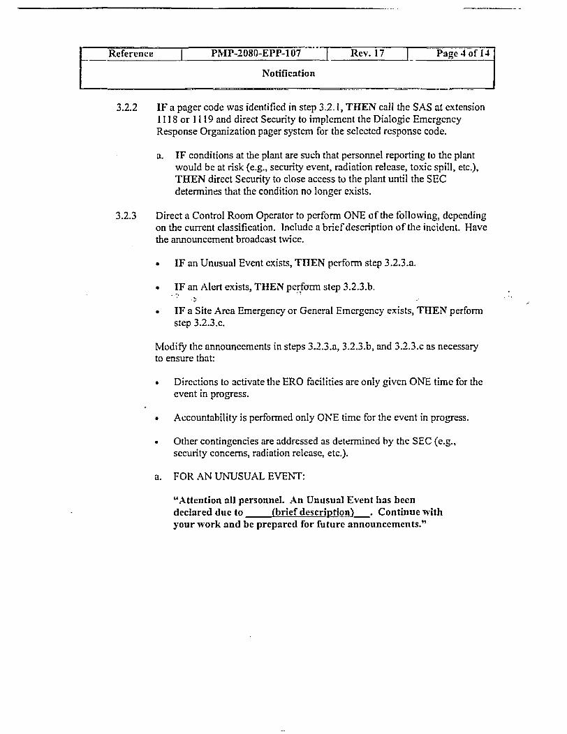
Reference PMP-2080-EPP-10_ Rev. 17 Pag 4 f i4
Notification
3.2.2 IF a pager code was identified in step 3.2.1, THEN call the SAS at extension1118 or II 19 and direct Security to implement the Dialogic EmergencyResponse Organization pager system for the selected response code.
a. IF conditions at the plant are such that personnel reporting to the plantwould be at risk (e.g., security event, radiation release, toxic spill, etc.),THEN direct Security to close access to the plant until the SECdetermines that the condition no longer exists.
3.2.3 Direct a Control Room Operator to perform ONE of the following, dependingon the current classification. Include a brief description of the incident. Havethe announcement broadcast twice.
* IF an Unusual Event exists, THEN perform step 3.2.3.a.
• IF an Alert exists, TIJEN perforn step 3.2.3.b.
* IF a Site Area Emergency or General Emergency exists, THEN performstep 3.2.3.c.
Modify the announcements in steps 3.2.3.a, 3.2.3.b, and 3..3.c as necessaryto ensure that:
Directions to activate the ERO facilities are only given ONE time for theevent in progress.
* Accountability is performed only ONE time for the event in progress.
* Other contingencies are addressed as determined by the SEC (e.g.,security concems, radiation release, etc.).
a. FOR .AN UNUSUAL EVENT:
"Attention all personnel. An Unusual Event has beendeclared due to (brief descriptioq_ Continue withyour work and be prepared for future announcements."
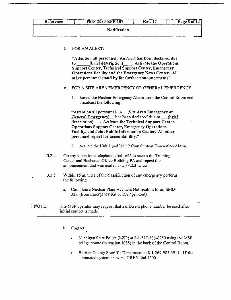
Reference PM[P-2080-EPP-107 J -Rv 7Page 5 of 14
Notification
b. FOR AN ALERT:
"Attention all personnel. An Alert has been declared dueto (brief description) . Activate the OperationsSupport Center, Technical Support Center, EmergencyOperations Facility and the Emergency Nevs Center. Allother personnel stand by for further announcements."
c. FOR A SITE AREA EMERGENCY OR GENERAL EMERGENCY:
I. Sound the Nuclear Emergency Alarm from the Control Room andbroadcast the following:
"Attention all personnel. A (Sjite Area Emerg4ency orGeneral Emergency z has been declared due to (briefdescnption) . Activate the Technical Support Center,Operations Support Center, Emergency OperationsFacility, and Joint Public Information Center. All otherpersonnel report for accountability."
2. Actuate the Unit I and Unit 2 Containment Evacuation Alarrn.
3.2.4 On any touch-tone telephone, dial 646 to access the TrainingCenter and Buchanan Office Building PA and repeat theannouncement that was made in step 3.2.3 twice.
3.2.5 Within 15 minutes of the classification of any emergency performthe following:
a. Complete a Nuclear Plant Accidcnt Notification form, EMID-32a, (from Emergency Kit or DAP printout).
NOTE: The MSP operator may request that a different phone number be used afterinitial contact is made.
b. Contact:
* Michigan State Police (MSP) at -1-517-336-6250 using the [SPbridge phone (extension l 088) in the back of the Control Room.
* Berrien County Sheriff's Department at 8-1-269-983-391 1. IF theautomated system answers, THEN dial 7200.
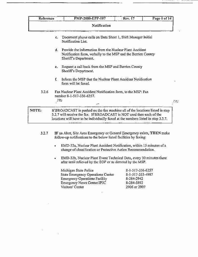
Reference | PrvP-2080-EPP-107 -Rev. 17 Page 6 of 14
Notification
c. Document phone calls on Data Sheet 1, Shifl Manager InitialNotification List.
d. Provide the inforrnation from the Nuclear Plant AccidentNotification forrn, verbally to the MSP and the Berrien CountySheriffs Department.
e. Request a call back from the MSP and Berrien CountySheriffs Department.
f. Inform the MSP that the Nuclear Plant Accident Notificationform will be faxed.
3.2.6 Fax Nuclear Plant Accident Notification form, to the MSP: Faxnumber 8-1-517-336-6257.
NOTE: If BROADCAST is pushed on the fax machine all of the locations listed in step3.2.7 will receive the fax. If BROADCAST is NOT used then each of thelocations will have to be individually faxed at the numbers listed in step 3.2.7.
3.2.7 IF an Alert, Site Area Emergency or General Emergency exists, THEN makefollow-up notifications to the below listed facilities by faxing:
a EMD-32a, Nuclear Plant Accident Notification, within 15 minutes of achange of classification or Protective Action Recommendation.
* EMD-32b, Nuclear Plant Event Technical Data, every 30 minutes thereafter until rclieved by the EOF or as directed by the MSP.
Michigan State PoliceState Emergency Operations CenterEmergency Operations FacilityEmergcncy News CenterfJPICVisitors' Center
8-1-517-336-62578-1-517-333-49878-284-29428-284-58922906 or 2907

Reference 'MP-2080-EPP-107 ev. 17 Page 7 of 14
I ~~~~~~~~~Notiication
3.2.8 IF a General Emergency exists and a PAR is made based on dose assessment,THEN within 15 minutes of the General Emergency classification or PARchange:
Complete an EMD-32a and EhID-32b form and make notifications asdirected in step 3.2.5 and fax the forms to the parties listed in step 3.2.7.
3.2.9 For all classifications, including classification upgrades, the ShiftManager or designee shall:
a. Provide the information on Data Sheet 2, Plant Status, to theNRC as soon as possible after the State and County have beennotified, and within one hour of classification.
* Make the notification in accordance with the instructions in PMP-7030-001-001, Prompt NRC Notification.
3.2.10 IF an emergency classification is upgraded or the PAR changes, THENverbally inform the MSP, Berrien County Sheriffs Department and the NRC.
Document phone calls to MSP and Berien County Sheriffs Department,on Data Sheet I, Shift Manager Initial Offsite Notification List.
3.2.11 Tnforrn the Security Shift Supervisor of the time of the EmergencyClassification.
a. Direct the Security Shift Supernisor to assume the responsibility of theSecurity Director.
b. Direct the Security Shift Supervisor to notify the personnel listed inSection 5 of the ERO Phone Directory of the Emergency Classification.
3.3 Drills, Exercises and Communication System Tests
3.3.1 IF a Drill or Exercisc is being conducted, THEN perform the applicableportions of Attachment 1.
3.3.2 IF a Communication System Ttest is being conducted, THEN perform theapplicable portions of Attachment 2.
4 FINAL CONDITIONS
4.1 Emergency. is closed-out.
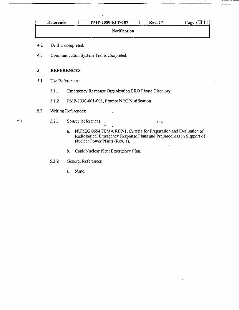
Reference I PP-2080-EPP-107 Rev. 17 Page 8 of 14
Notification
4.2 Drill is completed.
4.3 Communication System Test is completed.
5 REFERENCES
5.1 Use References:
5.1.1 Emergency Response Organization ERO Phone Directory.
5.1.2 PNIP-7030-001-001, Prompt NRC Notification
5.2 Writing Refercnces:
5.2.1 Source References:
a. NUREG 0654 FEMA REP-I, Criteria for Preparation and Evaluation ofRadiological Emergency Response Plans and Preparedness in Support ofNuclear Power Plants (Rev. ).
b. Cook Nuclear Plant Emergency Plan.
5.2.2 Gencral Refercnces
a. None.

1 DRILLS AND EXERCISES
1.1 IF an Alert, Site Area Emergency, or a General Emergency has been declared, THENthe Simulator Shift Manager calls the SAS at extension 41-1 I 18 and directs Security toimplement the Dialogic Emergency Response Organization pager system for anannounced or unannounced drill as dirccted by the controller. The drill or exercisecontroller may provide alternate instructions for contacting Security as dictated by thedrill scenario.
1.2 The Simulator Shift Manager requests that the Shift Manager have a control room staffmember page the plant using the Plant PA system, and make an announcement inaccordance with the drill controller's instructions.
1.3 The Simulator Shift MIanager directs the Simulator control room staff to sound theNuclear Emergency Alarn and the Containment Evacuation Alarm in theSIMULATOR for a Site Area Emergency or General Emergency.
1.4 The Simulator Shift Manager directs the Simulator unaffected control room staff topage the Training Building and Buchanan Office Building by dialing 41-1646 on theplant phone system, and make an announcement in accordance with the drillcontroller's instructions.
Reference I PNIP-2080-EPP-107 | Rev. 17 Page 9 of 14
Notification
Attachment I Drills and Exercises Page:___ ~~~~~~~~~~~~~~9

COMIVIUNICATION SYSTEM TESTS
1.1 I Nuclear Emergency Alarm Test and ERO Tumover'Notification Process Test
1.1 .1 Operating shift shall perform the following tests every Tuesday atapproximately 1 000 or at a time approved by the Shift Manager:
Call the SAS at extension 1 1 8 to direct Security to activate the DialogicEmergency Response Organization pagers for a Turnover.
1.1.2 Test Nuclear Emergency Alarm
Annoiunce:
"This is a test. The following is a test of the Nuclear EmergencyAlarm and ERO turnover notification."
* Sound the Nuclear Emergency Alarm (NEA) for 5 to 10 seconds and thenrcset by pushing "OVERIDE" button.
Announce:
"The test of the Nuclear Emergency Alarm is complete. Oncomingduty ERO personnel should call Dialogic wvhen the ERO pageractivates."
Acceptance Criteria:
NEA alarm is heard in the Control Room.
Print Name/Signature
Reference | PNIP-2080-EPP-107 Rev. 17 j Page 10 of 14
Notification
Attachment 2 Communication System Tests Pages:- - -10- 11
Date

1.1 .3 Perform test of the Training Building and Buchanan Office Building PublicAddress System.
* Dial 1646 and announce the following:
"This is a test of the Training Building and Buchanan OfficeBuilding Public Address System and ERO turnover notification.Oncoming duty ERO personnel should call Dialogic when the EROpager activates. Testis complete."
Acceptance Critcria: (only required to be verified during normal workdays).
Emergency Planning personnel report that PA systcm test is heard in theTraining Building and Buchanan Office Building.
Print Name/Signature Date
1.1.4 Perform the test of the Beach PA system monthly, between May andOctober 3 ".
* Station an AEO within range of the Beach PA system speakers.
* Make the following announcement using the Beach PA systemmicrophone.
* "This is a test of the Beach Public Address System. Test complete."
* Acccptance Criteria:
Announcement is hcard by the AEO stationed for the test.
Print Name/Signature Date
Reference I PrIP-2080-EPP-107 | Re.17 PaIge 11 of 14
Notification
Attachment 2 Communication System Tests Pages:1 to ~~~~~~~~1- 11
Pr-int NarnelSignature Datc
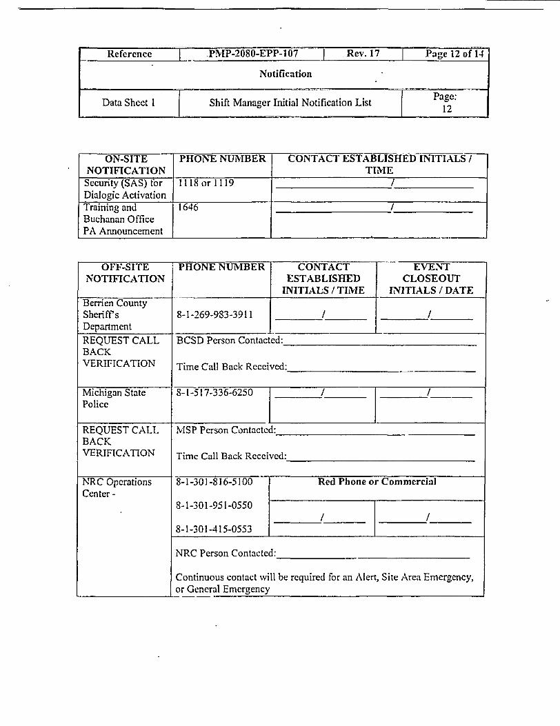
Referenc` T PMP-2080-EPP-107 cRev. Pae 12 of 14
Notification
Data Sheet Shift Manager Initial Notification ListPae1~2
ON-SITE PHONE NUNIBER CONTACT ESTABLISHED INITIALS /NOTIFICATION TIE
Security (SAS) for I I 18 or 1 19 /Dialogic ActivationTraining and 1646 /Buchanan OfficePA Announcement
OFF-SITE PHONE NUNIBER CONTACT EVENTNOTIFICATION ESTABLISHED CLOSEOUT
INITIALS / TIME INITIALS / DATEBerrien CountySheriff's 8-1-269-983-3911 / /Department . _
REQUEST CALL BCSD Person Contacted:_ _BACKVERIFICATION Time Call Back Received:_
Nlichigan State 8-1-517-336-6250 1 /Police
REQUEST CALL MvISP Person Contacted:_BACKVERIFICATION Time Call Back Received:_
[ _______ _____.____.____,____
NRC OperationsCenter -
8-1-301-816-5100
8-1-301-951-0550
8-1-301-415-0553
Red Phone or Commercial
/ I
NRC Person Contacted:_
Continuous contact will be required for an Alert, Site Area Emergency,or General Emergency

Reference PMIP-200-P17 _ . Rev. 17 j Pagc 13 of 11
Notification
NOTE: This Data Sheet is not required to be sent to the NRC unless asked for by theNRC. It is to be used as a guide for the communicator talking to the NRC.
Time of NRC Notification:
Reactivity Control
* All Control rods inserted? Yes No # of rods out
* Reactor Subcritical? Yes No
* Emergency Boration initiated? ;* Yes No
* Adequate Shutdown Mivargin? Yes No
RCS Inventory Control - Check all that apply for the current plantconditions
* Inventory makeup controlled by: (Identify all pumps injectinginto RCS)
CVCS - Normal Charging
Charging Pumps via BIT (High Head SI)
Safety injection pumps (Intermediate Head SI)
RHR Pumps (Low Head SI)
Other:
RCS Pressure Control
* Pressurizer PORVs Closed? Yes No
• Pressurizer Safeties Closed? Yes No

Reference PIP-2080-EPP-107 RPae 14 of 14
Notification
Data Sheet 2 Plant Status Pages:13 - 14
RCS Heat Transport Control - Check all that apply for the currentplant conditions
Forced Circulation by RCP
Natural Circulation
Feed and Bleed
Decay Heat Removal System (RHR)
RCS Heat Sink (available or in operation) - Check all that apply forthe current plant conditions
S 'G - Condenser Dump Valves
S/G -- Atmospherie Dump Valves
S/G - Safety Valves
RCS -- FeedlBleed
Decay Heat Removal System (RHR)
S/G Inventory Control - Check all that apply for the current plantconditions
lain Fcedwater
Aux. Feedwater
Other:
Containment Control
* Ice Condenser Doors OPEN? Yes No
* Containment Sprays ON? Yes No
* Hydrogen Recombiners/lgniters ON? Yes No
* Containment Isolation Valves fail to CLOSE? Yes No
* Plase A Actuation? Yes No
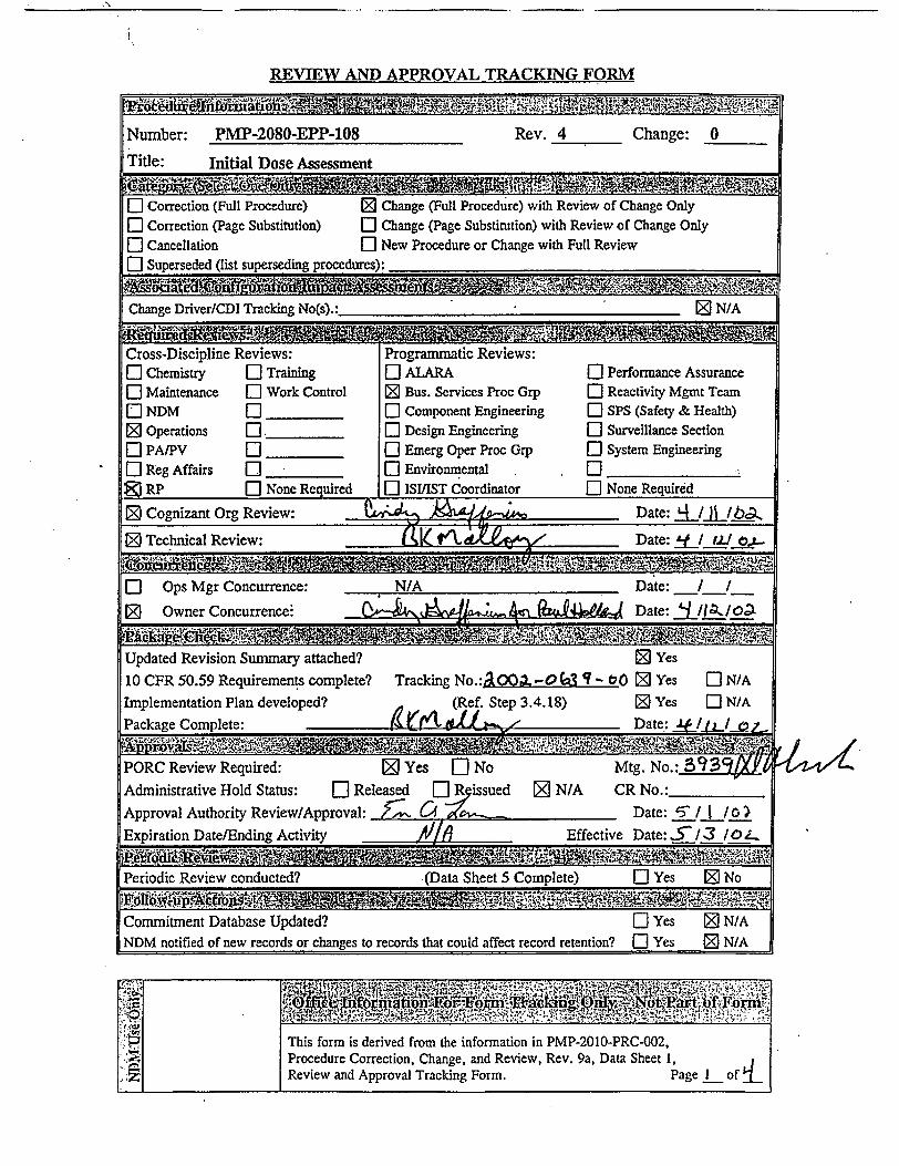
A
EVIEW AND APPROVAL TRACKING FORM
F%;..E£aS SPBsU'i7tJ% 0
Number: PMP-2080-EPP-108 Rev. 4 Change: 0
Title: Initial Dose Assessment
IajA/fr- :-| Correction (Full Procedure) 0 Change (Full Procedure) with Review of Change Only| Correction (Page Substitution) E Change (Page Substitution) with Review of Change OnlyED Cancellation El New Procedure or Change with Full ReviewEl Superseded (list superseding procedures):
Change Driver/CDI Tracking No(s).:_____ N/A
Cross-Discipline Reviews: Programmatic Reviews:El Chemistry E Training Ol ALARA El Performance Assurancel Maintenance O Work Control 0 Bus. Services Proc Grp a Reactivity Mgmt Team|[ NDM [:aComponent Engineering EO SPS (Safety & Health)3 Operations O. E Design Engineering El Surveillance Section
_PA/PV _ O Emerg Oper Proc Grp El System EngineeringD Reg Affairs O O Environmental . ._a
RP El None Required El ISIIST Coordinator E None Required
Cognizant Org Review: Q jDate: qt lJ b\la2Technical Review: ( t 1 ( Date: K 1 >
El Ops Mgr Concurrence: N/A Date: /0D Owner Concurrence ( .A- .L 's 9AQ41WwAe Date: L/la_/Ot
Updated Revision Summary attached? 0 Yes10 CFR 50.59 Requirements complete? Tracking No.a .- 0 (3 t¶-0 0 Yes E N/AImplementation Plan developed? (Ref. Step 3.4.18) 0 Yes El N/APackage Complete: - 9 1 Date: I.JjjL
PORC Review Required: 3 Yes E No Mtg. No.: 393BAdministrative Hold Status: El Released El R issued 3 N/A CR No.:Approval Authority Review/Approval: . Cl Date: I O I
Expiration Date/Ending Activity Effective Date:5J/3 lL
_NO W ,Periodic Review conducted? (Data Sheet S Complete) El Yes 0 No
Commitment Database Updated? Y Yes ON/ANDM notified of new records or changes to records that could affect record retention? El Yes 0 N/A
This form is derived from the information in PMP-2010-PRC-002,Procedure Correction, Change, and Review, Rev. 9a, Data Sheet 1,Review and Approval Tracking Form. Page I of L
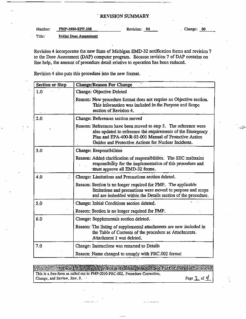
*REVISION SUMA%RY
Number: PMP-2080-EPP.108 Revision: 04
Title: Initial Dose Assessment
Revision 4 incorporates the new State of Michigan EMD-32 notification forms and revision 7to the Dose Assessment (DAP) computer program. Because revision 7 of DAP contains online help, the amount of procedure detail relative to operation has been reduced.
Revision 4 also puts this procedure into the new format.
Section or Step Change/Reason For Change
1.0 Change: Objective Deleted
Reason: New procedure format does not require an Objective section.This information was included in the Purpose and Scopesection of Revision 4.
2.0 Change: References section moved
Reason: References have been moved to step 5. The reference werealso updated to reference the requirements of the EmergencyPlan and EPA400-R-92-001 Manual of Protective ActionGuides and Protective Actions for Nuclear Incidents.
3.0 Change: Responsibilities
Reason: Added clarification of responsibilities. The SEC maintainsresponsibility for the implementation of this procedure andimust approve all EMD-32 forms.
4.0 Change: Limitations and Precautions section deleted.
Reason: Section is no longer required for PMP. The applicablelimitations and precautions were moved to purpose and scopeand are inbedded within the Details section of the procedure.
5.0 Change: Initial Conditions section deleted.
Reason: Section is no longer required for PMP.
6.0 Change: Supplementals section deleted.
Reason: The listing of supplemental attachments are now included inthe Table of Contents of the procedure as Attachments.Attachment 1 was deleted.
7.0 Change: Instructions was renamed to Details
Reason: Name changed to comply with PRC.002 fornat
0 .
This is a free-form as called out in PMP-2010-PRC-002, Procedure Correction,Change, and Review, Rev. 9. Page r of L
Change: 00

REVISION SUMMARY
PMP-2080EPP.108
Initial Dose Assessment.
Revision: 04
Section or Step Change/Reason For Change
7.0 Change: Section completely re-written
Reason: Revision 7 to the Dose Assessment Program provides on-linehelp and additional help for each object on the input andresults screens. Therefore detail about the actual operation ofthe program was eliminated from the procedure. The Detailssection of the procedure now provides the user instructions on:
* Which EMD-32 forms are required and at whatfrequency
* Where to obtain meteorological data
* Where to obtain radiological release data
; * Shut down status and times
* Determining coolant types
* Determining if a release is occurring
* Projected release duration
* Classification levels and initiating conditions
These are all items that must be obtained that are external to thedose assessment program, but are required for its operation.
The procedure also provides instruction for the disposition of theinformation to the state and county after the SEC approves theform(s).
Attachment 1 Change: The attachment was deleted
Reason: An Icon will be placed on thecomputers when the program isloaded on each computer. DAP provides on-line help to assistthe user with its operation.
This is a free-form as called out in PMP-2010-PRC-002, Procedure Correction,Change, and Review, Rev. 9. Page 3of d
Number:
Title:
Change: 00
........

REVISION SUMMARY
PMP-2080-EPP.i08. Revision: 04
Initial Dose Assessment
Number:
Title:
Change: 00
Section or Step Change/Reason For Change
Attachment 2 Change: Attachment 2 was split into attachment 1 and 2 of revision 4.
Reason: Attachment 1 of Rev 4 provides instructions for additionalmethods of obtaining meteorological data should the primarymethods be unavailable. Attachment 2 of Rev 4 containsadditional methods for determining Pasquill Category shouldthe primary method on the PPC/RDR be unavailable.
~~*~Qffic tQ'W,~o ra~n '~f F ~ ?%This is a free-form as called out in PMP-2010-PRC-002, Procedure Correction,Change, and Review, Rev. 9. Page q of 9
--

fLicni | PMP-2080-EPP-108 Rev. 4 Page 1 of 9
Initial Dose Assessment
Information Effective Date: 73 lot
P. E. Holland P. E. Holland Emergency PlanningWriter Owner Cognizant Organization
TABLE OF CONTENTS
1 PIPOSE AND SCOP13 ......................................... 2
2 DEFINITIONS AND ABBR1IEVIATIONS . . . 2
3 RE.SPONSIBLITES .. 2
4 DETAILS ... 3
5 REFERENCES ......................................... . .. 5
Attachment 1: Meteorological Data. 7
Attachment 2: Pasquill Category. 9

1 PURPOSE AND SCOPE
1.1 This procedure provides instructions for performing initial dose assessment forreleases of radioactive material from the plant.
1.2 Use of this procedure should be limited to actual emergencies and emergency drills.
2 DEFINITIONS AND ABBREVIATIONS
RESPONSIBILITIES
The SEC is responsible for the implementation of this procedure.
The SEC must review and approve all EMD-32a and EMD-32b forms prior totransmission to Berrien County or the State of Michigan. This is a non-delegableresponsibility.
Term Meaning
DAP Dose Assessment Computer Program
EMD-32a State of Michigan Emergency Notification form (NuclearPlant Event Notification)
EMD-32b State of Michigan Technical Notification form (Nuclear PlantEvent Technical Data)
PAR Protective Action Recommendation
PPC Plant Process Computer
RMS Radiation Monitoring System
SEC Site Emergency Coordinator
3
3.1
3.2

Information PMP-2080-EPP-108 Rev. 4 F- Page 3 of 9
Initial Dose Assessment
4 DETAILS
NOTE: DAP contains extensive on line help. Help for any particular subject may beobtained by placing the mouse over the object in question. If help is availableit will appear at the bottom of the screen.
NOTE: Dose assessment projections may only be performed using the DAP. Fprojected doses are NOT available and a PAR is necessary, THEN use thedefault PAR in PMP-2080-EPP-100.
4.1 Determine which forms are required.
4.1.1 EMD-32a, Nuclear Plant Event Notification.
Is only transmitted to the State/County within 15 minutes of a change tothe emergency classification or PAR.
Must include an EMD-32b, Nuclear Plant Event Technical Data Formif the emergency classification is General Emergency and the PAR isbased on dose calculations.
4.1.2 EMD-32b, Nuclear Plant Event Technical Data Form.
Required o be transmitted to the State/County within 30-minuteintervals of the last EMD-32b or EMD-32a form.
4.2 Obtain meteorological data from the PPC. If the PPC is not available, Attachment 1,Meteorological Data, contains additional sources of meteorological data andAttachment 2, Pasquill Category, provides for Pasquill Category (Stability Class)determinations.
NOTE: Sources are listed in order of preference.
* 10 Meter Main
* 10 Meter Backup
60 Meter Main

Information PMP-2080-EPP-108 I Rev. 4 Page 4 of 9
Initial Dose Assessment
4.3 Obtain RMS radiological data from one of the following sources:
NOTE: Sources are listed in order of preference.
PPC
* RMS Display Terminals
* Direct readings from the Local Area Data Acquisition Modules
4.4 Determine the Unit I and Unit 2 reactor shutdown status and the date and time ofshutdown as applicable.
4.5 Determine the Coolant Type.
Coolant Type Containment High Radiation Monitoring ReadingNormal Coolant < 10 R/hrCladding Damage < 1000 R/hrFuel Melt > = 1000 R/hr
4.6 Determine whether an actual or potential release is occurring.
4.6.1 An actual release is occurring when any of the following are true:
* Valid indication on release point radiation monitoring system channelsare present that are associated with a classified event,
- OR-
* Measured off-site radiation readings indicate a release is in progress,
- OR-
O Indications exist that an unmonitored release may be occurring.
4.6.2 A potential release exists if calculated data is postulated based on presentplant conditions (i.e., Containrnent Loss of Coolant Accident (LOCA)).

Information PMP-2080-EPP-108 [ Rev. 4 | Page 5 of 9
Initial Dose Assessment
4.7 Determine the Projected Duration of the Release.
IF the projected duration of the release is unknown, THEN use 1 hour.
IF releases are occurring from multiple points, TIEN use the longestprojected duration.
4.8 Enter the data into the Dose Assessment Program.
NOTE: The classifications may change based on the results of the assessment beingrun and must be updated accordingly prior to submitting the EMD-32a orEMD-32b forms for transmittal to the state or county.
4.9 IF necessary, THEN update the current classification and tiating Conditions onthe EMD-32a and EMD-32b.
4.10 Submit the EMD-32a and/or EMD-32b to the SEC.
4.11 The SEC approves the EMD-32 form(s).
4.12 Transmit the EMD-32 form(s) to the Berrien County Sheriff's Department and theState of Michigan.
5 REFERENCES
5.1 Use References:
5.1.1 Dose Assessment (DAP) Computer Program
5.1.2 EMD-32a, Nuclear Plant Event Notification
5.1.3 EMD-32b, Nuclear Plant Event Technical Data Form
5.2 Writing References:
5.2.1 Source References
a. Donald C. Cook Nuclear Plant Emergency Plan
b. EPA 400-R-92-001, Manual of Protective Action Guides and ProtectiveActions for Nuclear Incidents

Information PMP-2080-EPP-108 | Rev. 4_ Page 6 of 9
Initial Dose Assessment
c. Meteorology and Atomic Energy 1968, U. S. Atomic EnergyCommission
d. Evacuation Time Estimates for the D. C. Cook Nuclear Plant PlumeExposure Emergency Planning Zone HMM Associates July 1992
5.2.2 General References
a. Michigan Emergency Preparedness Plan
b. Berrien County Emergency Preparedness Plan
- - .......

Information PMP-2080-EPP-108 I Rev. 4 Page 7 of 9
Initial Dose Assessment
Attachment 1 Meteorological Data Pages:
NOTE: Wind speeds are expressed as Miles per Hour. To convert Knots to Miles perHour multiply by 1.15.
IF all of the following are true:
The current date is between April 15 and October 31,The current time is between 1-hour after sunrise and 1-hour after sunset,Ambient temperature measured at the main tower is greater than the LakeMichigan temperature,Wind speed on the shoreline tower is 5 13.4 Miles per Hour,Pasquill category is A, B, C, or D, ANDShoreline tower wind direction is FROM 2050 to 230 (i.e., Wind is fromthe lake)
THEN consider lake breezes in the dose assessment process.
1.1 Obtain meteorological data from one of the following sources. Sources are listed inorder of preference.
.1.1.1 Plant Process Computer
10 Meter Main10 Meter Backup
* 60 Meter Main
1.1.2 Murray and Trettle
a. Obtain the phone number from the Emergency Response OrganizationPhone Directory.
b. Obtain:
Wind Speed in Miles per HourWind Direction from, in degreesPasquill Category as a letter NOT a numberEight-hour and 24-hour meteorological forecast
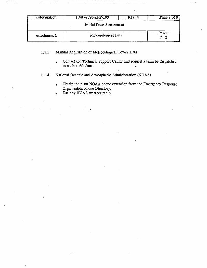
1.1.3 Manual Acquisition of Meteorological Tower Data
* Contact the Technical Support Center and request a team be dispatchedto collect this data.
1.1.4 National Oceanic and Atmospheric Administration (NOAA)
* Obtain the plant NOAA phone extension from the Emergency ResponseOrganization Phone Directory.
* Use any NOAA weather radio.
Information PMP-2080-EPP-108 T Rev. 4 Page 8 of 9
Initial Dose Assessment
Attachment 1 Meteorological Data Pages:

1 Obtain Pasquill Category datain order of preference.
1.1 Plant Process Computer
1.2 Temperature Differential
1.3
1.4
1.5
from one of the following sources. Sources are listed
AT°F =T@60m-T@10m Pasquill Category aT OC = T a 60m - T @ lOm(Z 50 Meters) (Z = 50 Meters)
_____ _ _._-_:A_-.;._,- .', ., =,°C ,1;O.::,.-1.8 < AT °F - 1.6 B -1.0 < AT OC s 0-.9
,:-li.6'! 0:AT F, : q .4 .. C', . -0.9< AThC O.8:.-1.4 < AT OF S- 0.5 D -0.8 < AT QC - 0.3
,, ; '-,$,'cE-[,oF ,+t'3' ::- E -.. :>,:-.:L . 403< A;T,C-S.+0.7-+1.3 < AT°F s +3.6 F +0.7 < T 0C s +2.0
.'-,-' i .G. : : .. -.0:<:T;0C
Standard Deviation of the Horizontal Wind Direction (STD)STD Pasquill Category
* ,, STD 2 Z.25 ..,.",''
22.5 STD > 17.5 B' : "1 .5.'.S D > 12.5 C12.5 > STD > 7.5 D
. i . 5 ~ ~ T D > 3 . 8 .3f83.8 2 STD > 2.1 F† . i:. ,'L2.1ST'-D G
Murray and Trettle* See Attachment 1, Meteorological Data.
ObservationIncoming Solar Radiation (Day Only)
(1 hour after sunrise to 1 hour before sunset)Sun Angle Cloud Cover
Degrees from Horizon None 1/8 - S/8 518 - 7/8 8/8Middle Clouds Low Clouds
.. ' 5°,!35o 7.; *9Slight Slight :'- - . * ligIitj: . . : Sigbt , Slight35o . 60. Moderate Slight Slight I Slight Slight
.. ; .6,,, .. , :$1ro ngStrong ' - _ .. S ; Slight
Day NihtWind Speed @ 10 meters Incoming Solar Radiation Thinly Overcast or < 318
Miles per Hour (Mph) Strong . Moderate Slight 2 4/8 Low Clouds CloudsMph 5 . A A-B .B --
5 < Mph7 A-B B C E F7 <MphSll ' B B-C C D E
11 < Mph< 13 C C -D D D DMph > 13 C D D D D
Information PMP-2080-EPP-108 Rev. 4 T Page 9 of 9
Initial Dose Assessment
Attachment 2 Pasquill Category Page: