atsc standard: non-real-time content delivery€¦ · · 2017-06-121 atsc standard: non-real-time...
TRANSCRIPT

1
ATSC Standard: Non-Real-Time Content Delivery
Advanced Television Systems Committee 1776 K Street, N.W. Washington, D.C. 20006 202-872-9160
A/103:2014 25 July 2014

ATSC A/103:2014 Non-Real-Time Content Delivery 25 July 2014
2
The Advanced Television Systems Committee, Inc., is an international, non-profit organization developing voluntary standards for digital television. The ATSC member organizations represent the broadcast, broadcast equipment, motion picture, consumer electronics, computer, cable, satellite, and semiconductor industries.
Specifically, ATSC is working to coordinate television standards among different communications media focusing on digital television, interactive systems, and broadband multimedia communications. ATSC is also developing digital television implementation strategies and presenting educational seminars on the ATSC standards.
ATSC was formed in 1982 by the member organizations of the Joint Committee on InterSociety Coordination (JCIC): the Electronic Industries Association (EIA), the Institute of Electrical and Electronic Engineers (IEEE), the National Association of Broadcasters (NAB), the National Cable & Telecommunications Association (NCTA), and the Society of Motion Picture and Television Engineers (SMPTE). Currently, there are approximately 120 members representing the broadcast, broadcast equipment, motion picture, consumer electronics, computer, cable, satellite, and semiconductor industries.
ATSC Digital TV Standards include digital high definition television (HDTV), standard definition television (SDTV), data broadcasting, multichannel surround-sound audio, and satellite direct-to-home broadcasting.
NOTE: The user's attention is called to the possibility that compliance with this standard may require use of an invention covered by patent rights. By publication of this standard, no position is taken with respect to the validity of this claim or of any patent rights in connection therewith. One or more patent holders have, however, filed a statement regarding the terms on which such patent holder(s) may be willing to grant a license under these rights to individuals or entities desiring to obtain such a license. Details may be obtained from the ATSC Secretary and the patent holder.
Revision History Version Date A/103:2012 standard approved 9 May 2012 Candidate Standard approved by TG1 12 November 2013 Revision of CS approved by TG1/S13 6 May 2014 A/103:2014 standard approved 25 July 2014

ATSC A/103:2014 Non-Real-Time Content Delivery 25 July 2014
3
Table of Contents
1. SCOPE 12 1.1 Introduction and Background 12 1.2 Organization 12
2. REFERENCES 13 2.1 Normative References 13 2.2 Informative References 16
3. DEFINITION OF TERMS 17 3.1 Compliance Notation 17 3.2 Treatment of Syntactic Elements 17
3.2.1 Reserved Elements 18 3.3 Acronyms and Abbreviations 18 3.4 Terms 20 3.5 Extensibility 20
3.5.1 Descriptor Processing Considerations 21 3.6 XML Schema and Namespace 22
4. SYSTEM OVERVIEW 23 4.1 System Architecture 23
4.1.1 Fixed-Broadcast NRT System Architecture 23 4.1.2 Mobile Broadcast NRT System Architecture 26
4.2 Content Item Concept 27 4.3 Consumption Models 27 4.4 Launching Content Items 28
5. CONTENT DELIVERY SPECIFICATIONS 29 5.1 IP Delivery via Broadcast 29
5.1.1 ATSC Fixed Broadcasts 29 5.1.2 ATSC Mobile Broadcasts 30
5.2 Broadcast File Delivery 30 5.2.1 Introduction to FLUTE 30 5.2.2 LCT and FLUTE Constraints 30 5.2.3 FLUTE FDT Extensions for Linkage of Files to Content Items 31 5.2.4 Forward Error Correction (FEC) 32 5.2.5 FDT Instance Compression 34 5.2.6 Filename Extensions and Internet Media Types 34 5.2.7 File Names and Hyperlink Resolution 36 5.2.8 Buffer Model 38

ATSC A/103:2014 Non-Real-Time Content Delivery 25 July 2014
4
5.2.9 Content Update Notification 38 5.2.10 File Delivery to Support RME Streams 40
5.3 Internet File Delivery 40 5.3.1 Multi-file HTTP Streaming Request 41 5.3.2 Multi-file HTTP Streaming Response 42 5.3.3 Recommended Receiver Behavior 43
5.4 File Compression 44 5.5 ZIP Archive Format 44
5.5.1 Zip Archive with a Start/Entry File 44 5.5.2 ZIP Archive with no Start/Entry File 44
6. SIGNALING AND ANNOUNCEMENTS FOR FIXED NRT BROADCASTS 47 6.1 Non-Real-Time Services 47
6.1.1 Standalone NRT Services 48 6.1.2 Adjunct NRT Services 48 6.1.3 NRT Protocol Version Identification 48 6.1.4 Service Signaling Channel 49 6.1.5 Structure of SSC Tables 49
6.2 Service Map Table (SMT) 50 6.2.1 Subnet-Level SMT Descriptors 51 6.2.2 Service-Level SMT Descriptors 51 6.2.3 Component-Level SMT Descriptors 52
6.3 Non-Real-Time Information Table (NRT-IT) 53 6.4 Text Fragment Table (TFT) 60 6.5 Purchase Information Tables 62
6.5.1 Purchase Item Table 63 6.5.2 Purchase Terms and Channels Table 67
7. SIGNALING AND ANNOUNCEMENTS FOR MOBILE NRT BROADCASTS 72 7.1 Signaling for Mobile NRT Broadcasts 72
7.1.1 Overview 72 7.1.2 Background on ATSC-M/H Signaling 72 7.1.3 Signaling NRT Services in the Service Map Table 73 7.1.4 SMT-MH Descriptors 74 7.1.5 Mapping FLUTE Files to Content Elements in the Service Guide 75
7.2 Announcement for Mobile NRT Broadcasts 75 7.2.1 Overview 75 7.2.2 Relationship to Mobile NRT Signaling 75 7.2.3 Approach for Announcing Mobile NRT Services and Content 76 7.2.4 ATSC Mobile NRT Service Guide Data Model 76
8. BASIC DESCRIPTORS 92 8.1 Protocol Version Descriptor (PVD) 93

ATSC A/103:2014 Non-Real-Time Content Delivery 25 July 2014
5
8.2 NRT Service Descriptor 95 8.3 Capabilities Descriptor 96 8.4 Icon Descriptor 100 8.5 ISO-639 Language Descriptor 101 8.6 FLUTE Component Descriptor Extension 102 8.7 Time Slot Descriptor 102 8.8 Internet Location Descriptor 105 8.9 Associated Service Descriptor 106 8.10 Multimedia EPG Linkage Descriptor 106 8.11 2D_3D_Corresponding_Content_Descriptor in NRT-IT 108
9. RECEIVER TARGETING 108 9.1 Introduction 108 9.2 Receiver Targeting Descriptor 109 9.3 Receiver Targeting XML Element 110 9.4 Targeting Criterion Table 113
10. INTERACTION CHANNEL 116
ANNEX A : CAPABILITY CODE DETAILS 117 A.1 Overview of capability signaling 117 A.2 List of Capability Codes with semantics 118
A.2.1 Capability Code 0x01: FLUTE Protocol 119 A.2.2 Capability Code 0x10: Compact No-Code FEC Scheme 119 A.2.3 Capability Code 0x11: Raptor Algorithm 119 A.2.4 DECE CFF Multimedia Container Format 119 A.2.5 Capability Code 0x25: ISO Base Media File Format for AAC Audio 121 A.2.6 Capability Code 0x26: ATSC Compliant MPEG-2 Transport Stream 121 A.2.7 Capability Code 0x27: PD2 Media Profile 121 A.2.8 Capability Code 0x41: AVC Standard Definition Video 121 A.2.9 Capability Code 0x42: AVC High Definition Video 121 A.2.10 Capability Code 0x43: AC-3 Audio 122 A.2.11 Capability Code 0x44: Enhanced AC-3 Audio 122 A.2.12 Capability Code 0x45: MP3 Audio 123 A.2.13 Capability Code 0x46: Browser Profile A 123 A.2.14 Capability Code 0x48: Atom 123 A.2.15 Capability Code 0x49: AVC Mobile Video 123 A.2.16 Capability Code 0x4A: HE AAC v2 Mobile Audio 123 A.2.17 Capability Code 0x4B: HE AAC v2 Profile, Level 4 Audio 123 A.2.18 Capability Code 0x4C: DTS-HD Audio 124 A.2.19 Capability Code 0x4D: CFF-TT 124 A.2.20 Capability Code 0x4E: CEA 708 Captions 124 A.2.21 Capability Code 0x4F: HE AAC v2 Audio with MPEG Surround 124

ATSC A/103:2014 Non-Real-Time Content Delivery 25 July 2014
6
A.2.22 Capability Code 0x50: HE AAC v2 Profile, Level 6 Audio 124 A.2.23 Capability Code 0x51: 3D video in Side-by-Side format 124 A.2.24 Capability Code 0x52: 3D video in Top-and-Bottom format 125 A.2.25 Capability Code 0x60: 56 Kbps Internet Connection 125 A.2.26 Capability Code 0x61: 512 Kbps Internet Connection 125 A.2.27 Capability Code 0x62: 56 Kbps Internet Connection 125 A.2.28 Capability Code 0x63: 56 Kbps Internet Connection 125 A.2.29 Capability Code 0x21: ZIP Format 125 A.2.30 Capability Code 0x28: W3C Web Apps Package 125 A.2.31 Capability Code 0x30: DEFLATE Algorithm 125
ANNEX B : NRT SERVICE CONSUMPTION MODELS 126 B.1 Introduction 126 B.2 Content Item Handling under Different Consumption models 128
B.2.1 Browse and Download Consumption Model 128 B.2.2 Push Consumption Model 128 B.2.3 Portal Consumption Model 129 B.2.4 Triggered Consumption Model 129 B.2.5 Push Scripted Consumption Model 130 B.2.6 Portal Scripted Consumption Model 130 B.2.7 EPG Consumption Model 130
B.3 Browse and Download 131 B.3.1 Browsing For Content 131 B.3.2 Selecting Content for Viewing 132
B.4 Push 133 B.5 Portal 134
ANNEX C : CAPABILITY CODE SIGNALING EXAMPLE 136 C.1 Scope 136 C.2 European Travel Destination NRT Service Example 136
ANNEX D : “BROWSER PROFILE A” SPECIFICATION 138 D.1 Scope 138 D.2 Browser Profile A 138
D.2.1 CE-HTML 138 D.2.2 User Interface Profile 140 D.2.3 Optional Elements 140 D.2.4 Summary 141
ANNEX E : DTS-HD FILE STRUCTURE 143 E.1 Introduction 143 E.2 Chunks 143
E.2.1 Chunk Parsing 143 E.2.2 Chunk Order and Navigation 144

ATSC A/103:2014 Non-Real-Time Content Delivery 25 July 2014
7
E.2.3 Chunk Notation 144 E.2.4 DTSHDHDR 144 E.2.5 FILEINFO 146 E.2.6 CORESSMD 146 E.2.7 EXTSS_MD 147 E.2.8 AUPR-HDR 148 E.2.9 AUPRINFO 149 E.2.10 NAVI-TBL 150 E.2.11 BITSHVTB 150 E.2.12 STRMDATA 150 E.2.13 TIMECODE 151 E.2.14 BUILDVER 151 E.2.15 BLACKOUT 151 E.2.16 BRANCHPT 152
ANNEX F : AC-3 AND E-AC-3 FILE FORMATS 153 F.1 Introduction 153 F.2 Specification 153
F.2.1 Dataframe Type 0x0B 154 F.2.2 Dataframe Type 0x77 154
ANNEX G : MPEG-4 FORMAT FOR AVC VIDEO WITH HE AAC V2 AUDIO 155 G.1 Introduction 155 G.2 MP4 Elementary Stream Tracks 155
G.2.1 Elementary Stream (ES) Descriptors 155 G.2.2 Object Descriptors 156
G.3 MP4 Track Identifiers 156 G.4 Synchronization of Streams 157 G.5 Media Composition 157
G.5.1 Video Media Header 158 G.5.2 Maximum Bit Rate 158 G.5.3 Sequence Parameter Set (SPS) 158 G.5.4 Visual Usability Information (VUI) Parameters 158 G.5.5 Picture Formats 158 G.5.6 Closed Captioning, AFD, and Bar Data 159
G.6 File Identification 159 G.6.1 Container Profile Identification 159 G.6.2 File Structure 160 G.6.3 Encryption 160
G.7 Additions To ISO Base Media Format 160 G.7.1 Object Descriptor Box 160 G.7.2 Track Reference Types 160

ATSC A/103:2014 Non-Real-Time Content Delivery 25 July 2014
8
G.7.3 Track Header Box 161 G.7.4 MP4 Media Header Boxes 161 G.7.5 Sample Description Boxes 161

ATSC A/103:2014 Non-Real-Time Content Delivery 25 July 2014
9
Index of Tables and Figures
Table 5.1 Filename Extensions and Content-Type Strings 36 Table 5.2 XML Schema Description for MultiFileRequest Element 41 Table 5.3 Extension Structure 45 Table 5.4 HTTP Entity Header Extension Syntax 46 Table 6.1 Service ID Descriptor Syntax 47 Table 6.2 Adjunct Services for Linear TV Service – Expected Receiver Behavior 48 Table 6.3 Service-Level Descriptors in the Service Map Table 52 Table 6.4 Component-Level Descriptors in the Service Map Table 53 Table 6.5 Bit Stream Syntax for the Non-Real-Time Information Table 54 Table 6.6 Content-Level Descriptors in the NRT-IT 59 Table 6.7 Bit Stream Syntax for the Text Fragment Table 61 Table 6.8 Syntax of Purchase Item Table 64 Table 6.9 Syntax of Purchase Terms and Channels Table 68 Table 7.1 Service Fragment 77 Table 7.2 SMT-Related Private Extensions 79 Table 7.3 Content Defaults 81 Table 7.4 Associated Services 81 Table 7.5 Schedule Fragment 82 Table 7.6 Distribution Window 83 Table 7.7 Presentation Window 84 Table 7.8 Content Fragment 84 Table 7.9 Content-Level Private Extensions 87 Table 7.10 PurchaseItem Fragment 91 Table 7.11 PurchaseData Fragment 92 Table 8.1 Bit Stream Syntax for the Protocol Version Descriptor 93 Table 8.2 Protocol Identifier 93 Table 8.3 Protocol Version for protocol_identifier = 0x02 (IP Subnet) 94 Table 8.4 Protocol Version for protocol_identifier = 0x03 (NRT) 94 Table 8.5 Bit Stream Syntax for the NRT Service Descriptor 95 Table 8.6 NRT Consumption Models 96 Table 8.7 Capabilities Descriptor Syntax 97 Table 8.8 Capability Categories and Registries 100 Table 8.9 Bit Stream Syntax for the Icon Descriptor 101 Table 8.10 Bit Stream Syntax for Component Data for FLUTE File Delivery
(Type 38) as Modified For NRT 102

ATSC A/103:2014 Non-Real-Time Content Delivery 25 July 2014
10
Table 8.11 Bit Stream Syntax for the Time Slot Descriptor 103 Table 8.12 Time Slot Types and Parameters 104 Table 8.13 Bit Stream Syntax for the Internet Location Descriptor 105 Table 8.14 Bit Stream Syntax for the Associated Service Descriptor 106 Table 8.15 Syntax of the Multimedia EPG Linkage Descriptor 107 Table 8.16 Role 107 Table 8.17 Bit Stream Syntax of 2D-3D Corresponding Content Descriptor 108 Table 9.1 Bit Stream Syntax for the Receiver Targeting Descriptor 109 Table 9.2 Targeting Criterion Type Codes 110 Table 9.3 Bit Stream Syntax for the Targeting Criterion Table 114 Table A.1 Capability Codes 118 Table B.1 Typical Expected Content Types and Characteristics of NRT Usage Models 127 Table C.1 Example Service Description 136 Table C.2 Example Content Description 136 Table C.3 Receiver Behavior 137 Table D.1 Required and Optional Functionality for BPACR (Informative) 142 Table E.1 List of Defined Chunks 143 Table E.2 DTS-HD File Organization 144 Table E.3 Time Code Data 145 Table E.4 Reference Clock Period 145 Table E.5 TC_Frame_Rate Code 145 Table E.6 Bitw_Stream_Metadata Bit Fields Syntax 146 Table E.7 FILEINFO Metadata 146 Table E.8 Core Sub-Stream Metadata 146 Table E.9 Loudspeaker Masks 147 Table E.10 Extension Sub-Stream Metadata 147 Table E.11 Audio Presentation Header Metadata 148 Table E.12 Bitw_Aupres_Metadata Bit Fields Syntax 149 Table E.13 Audio Presentation Information Text 149 Table E.14 Navigation Metadata 150 Table E.15 Bit Shaving Metadata 150 Table E.16 DTS-HD Encoded Stream Data 151 Table E.17 DTS-HD Timecode Data 151 Table E.18 DTS-HD BuildVer Data 151 Table E.19 DTS-HD Encoded Blackout Data 151 Table E.20 Branch Point Metadata 152 Table F.1 AC-3 and E-AC-3 File Structure 153 Table F.2 Dataframe Type 0x0B Syntax 154

ATSC A/103:2014 Non-Real-Time Content Delivery 25 July 2014
11
Table F.3 Dataframe Type 0x77 Syntax 154 Table G.1 Picture Formats and Constraints 159 Table G.2 Frame Rate Constraints and Associated Parameters 159 Figure 4.1 Signaling of IP Subnet carrying NRT services for Fixed Broadcast. 23 Figure 4.2 NRT services in the IP transport. 25 Figure 7.1 ATSC-M/H Hierarchical Signaling Architecture. 73 Figure 8.1 Parameters in Time Slot Descriptor – Example. 104 Figure B.1 Example content selection UI. 132 Figure B.2 Example Push service subscription screen. 133 Figure B.3 Portal page example. 134 Figure D.1 XHTML browser block diagram. 139
ATSC A/103:2014 Non-Real-Time Content Delivery 25 July 2014
12
ATSC Standard: Non-Real-Time Content Delivery (A/103:2014)
1. SCOPE This Standard describes the ATSC Non-Real-Time Content Delivery system, hereafter referred to as the ATSC NRT system or simply NRT. The NRT system provides support for delivery of content in advance of use (i.e., not streaming content). These ATSC-NRT services are carried in DTV broadcast multiplexes. The presence of these services do not preclude or prevent operation of current ATSC services in the same RF channel or have any adverse impact on legacy receiving equipment.
This Standard was prepared by the Advanced Television Systems Committee (ATSC) Technology and Standards Group (TG1) Specialist Group on Data Broadcast. It was first approved by the full membership of the ATSC on 9 May 2012. ATSC Standard A/103:2014 was approved by the full membership on 25 July 2014.
1.1 Introduction and Background Consumer expectations about sources of entertainment and information are undergoing a dramatic transformation, including an increasing desire for “everything-on-demand”. At the same time, technology is rapidly changing to enable new consumption and distribution models—significant amounts of storage capacity are appearing in receiving devices, personal media players have become commonplace and inter-device connectivity has become practical. These factors combine to allow a shift from linear TV viewing to on-demand consumption of content. One of the main enablers of this shift is the capability for Non-Real-Time delivery of content—content that is delivered in advance of its use and stored in the receiving device.
The NRT content can include both “traditional” TV fare (video/audio entertainment programming, news, weather, sports, etc.), information that is not now part of traditional TV fare or that is presented in a customized and non-traditional way as well as information not aimed at the TV at all (including content targeted to PCs, handheld media players or even commercial platforms).
Typical applications for NRT services include: • Push VOD (content ranging from short-form video clips to feature length movies) • News, information and weather services • Personalized TV channels • Music distribution • Reference information on a wide range of topics Delivery of Non-Real-Time services allows broadcasters to continue to capitalize on a unique
advantage—the efficient delivery of localized content wirelessly to devices. The development of complete end-to-end standards to enable NRT service delivery is a critical part of the future of broadcasting.
1.2 Organization This document is organized as follows:

ATSC A/103:2014 Non-Real-Time Content Delivery 25 July 2014
13
• Section 1 – Outlines the scope of this document and provides a general introduction • Section 2 – Lists references and applicable documents • Section 3 – Provides a definition of terms, acronyms, and abbreviations for this document • Section 4 – System overview • Section 5 – Content delivery specifications • Section 6 – Signaling and announcements for fixed NRT broadcasts (normative) • Section 7 – Signaling and announcements for mobile NRT broadcasts (normative) • Section 8 – Basic descriptors • Section 9 – Receiver targeting • Section 10 – Interaction channel • Annex A – Capability code details • Annex B – NRT service categories • Annex C – Capability code signaling examples • Annex D – Specifications of “Browser Profile A” • Annex E – DTS-HD file structure • Annex F – AC-3 and E-AC-3 file formats • Annex G – Additions to ISO Base Media Format
2. REFERENCES All referenced documents are subject to revision. Users of this Standard are cautioned that newer editions might or might not be compatible.
2.1 Normative References The following documents, in whole or in part, as referenced in this document, contain specific provisions that are to be followed strictly in order to implement a provision of this Standard. [1] ATSC: “Digital Audio Compression Standard (AC-3, E-AC-3),” Document A/52:2012,
Advanced Television Systems Committee, Washington, D.C., 17 December 2012. [2] ATSC: “ATSC Data Broadcast Standard,” Doc A/90:2013, Advanced Television Systems
Committee, Washington, D.C., 28 October 2013. [3] ATSC: “ATSC Digital Television Standard, Part 3 – Service Multiplex and Transport
Subsystem Characteristics,” Document A/53 Part 3:2009, Advanced Television Systems Committee, Washington, D.C., 7 August 2009.
[4] ATSC: “ATSC Digital Television Standard, Part 4 – MPEG-2 Video System Characteristics,” Document A/53 Part 4:2009, Advanced Television Systems Committee, Washington, D.C., 7 August 2009.
[5] ATSC: “ATSC Digital Television Standard, Part 5 – AC-3 Audio System Characteristics,” Document A/53, Part 5:2010, Advanced Television Systems Committee, Washington, D.C., 6 July 2010.
[6] ATSC: “ATSC Interaction Channel Protocols,” Document A/96, Advanced Television Systems Committee, Washington, D.C., 3 February 2004.
[7] ATSC: “ATSC 3D Digital Television Standard, Part 3 – 3D Frame Compatible Coding using Real-time Delivery,” Doc. A/104, Part 3:2014, Advanced Television Systems Committee, Washington, D.C., 27 June 2014.

ATSC A/103:2014 Non-Real-Time Content Delivery 25 July 2014
14
[8] ATSC: “ATSC-Mobile DTV Standard, Part 3 – Service Multiplex and Transport Subsystem Characteristics,” Document A/153 Part 3:2009, Advanced Television Systems Committee, Washington, D.C., 15 October 2009.
[9] ATSC: “ATSC-Mobile DTV Standard, Part 4 – Announcement” Document A/153 Part 4:2009, Advanced Television Systems Committee, Washington, D.C., 15 October 2009.
[10] ATSC: “ATSC-Mobile DTV Standard, Part 7 – AVC and SVC Video System Characteristics,” Document A/153 Part 7:2012, Advanced Television Systems Committee, Washington, D.C., 4 July 2012.
[11] ATSC: “ATSC-Mobile DTV Standard, Part 8 – HE AAC Audio System Characteristics,” Document A/153 Part 8:2012, Advanced Television Systems Committee, Washington, D.C., 18 December 2012.
[12] ATSC: “Content Identification and Labeling for ATSC Transport,” Document A/57B, Advanced Television Systems Committee, Washington, D.C., 26 May 2008.
[13] ATSC: “DTV Application Software Environment Level 1 (DASE-1) Part 1: Introduction, Architecture, and Common Facilities,” Doc. A/100-1, Advanced Television Systems Committee, Washington, D.C., 9 March 2003.
[14] ATSC: “Program and System Information Protocol for Terrestrial Broadcast and Cable,” Document A/65:2009, Advanced Television Systems Committee, Washington, D.C., 14 April 2009.
[15] ATSC: “Video System Characteristics of AVC in the ATSC Digital Television System,” Document A/72 Part 1:2008, Advanced Television Systems Committee, Washington, D.C., 29 July 2008.
[16] CEA: “Digital Television (DTV) Closed Captioning,” CEA-708-D, Consumer Electronics Association, Arlington, VA.
[17] CEA: “Web-based Protocol and Framework for Remote User Interface on UPnP™ Networks and the Internet (Web4CE),” CEA-2014-B, Consumer Electronics Association, Arlington, VA.
[18] DECE: “Common File Format & Media Formats Specification, Version 1.0.7r2,” Digital Entertainment Content Ecosystem (DECE) LLC, 30 October 2013. http://www.uvvuwiki.com/
[19] ECMA: “ECMAScript Language Specification, 5th Edition,” ECMA-262, December 2009. [20] SCTE: “DTS-HD Audio System – Part 1: Coding Constraints for Cable Television,” SCTE
194-1 2013, Society of Cable Telecommunications Engineers. [21] IEEE: “Use of the International Systems of Units (SI): The Modern Metric System”, Doc.
IEEE/ASTM SI 10-2002, Institute of Electrical and Electronics Engineers, New York, N.Y., 2002.
[22] IETF: “Asynchronous Layered Coding (ALC) Protocol Instantiation,” RFC 5775, Internet Engineering Task Force, Reston, VA, April 2010.
[23] IETF: “DEFLATE Compressed Data Format Specification version 1.3,” RFC 1951, Internet Engineering Task Force, Reston, VA, May 1996.
[24] IETF: “FLUTE – File Delivery over Unidirectional Transport,” RFC 6726, Internet Engineering Task Force, Reston, VA, November 2012.
[25] IETF: “Host Extensions for IP Multicasting,” RFC 1112, Internet Engineering Task Force, Reston, VA, August 1989.

ATSC A/103:2014 Non-Real-Time Content Delivery 25 July 2014
15
[26] IETF: “HTTP Over TLS,” RFC 2818, Internet Engineering Task Force, Reston, VA, May 2000.
[27] IETF: “Hypertext Transfer Protocol -- HTTP/1.1,” RFC 2616, Internet Engineering Task Force, Reston, VA, June 1999.
[28] IETF: “Internationalized Resource Identifiers (IRIs),” RFC 3987, Internet Engineering Task Force, Reston, VA, January 2005.
[29] IETF: “Known Issues and Best Practices for the Use of Long Polling and Streaming in Bidirectional HTTP,” RFC 6202, Internet Engineering Task Force, Reston, VA, April 2011.
[30] IETF: “Layered Coding Transport (LCT) Building Block,” RFC 5651, Internet Engineering Task Force, Reston, VA, October 2009.
[31] IETF: “MIME Type Registration for MPEG-4,” RFC 4337, Internet Engineering Task Force, Reston, VA, March 2006.
[32] IETF: “Multipurpose Internet Mail Extensions (MIME) Part One: Format of Internet Message Bodies”, RFC 2045, Internet Engineering Task Force, Reston, VA, November 1996.
[33] IETF: “Multipurpose Internet Mail Extensions (MIME) Part Two: Media Types,” RFC 2046, Internet Engineering Task Force, Reston, VA, November 1996.
[34] IETF: “PNG (Portable Network Graphics) Specification Version 1.0,” RFC 2083, Internet Engineering Task Force, Reston, VA, March 1997.
[35] IETF: “Real-time Transport Protocol (RTP) Payload Format for Enhanced AC-3 (E-AC-3) Audio,” RFC 4598, Internet Engineering Task Force, Reston, VA, July 2006.
[36] IETF: “RTP Payload Format for AC-3 Audio,” RFC 4184, Internet Engineering Task Force, Reston, VA, October 2005.
[37] IETF: “Scripting Media Types,” RFC 4329, Internet Engineering Task Force, Reston, VA, April 2006.
[38] IETF: “SDP: Session Description Protocol,” RFC 4566, Internet Engineering Task Force, Reston, VA, July 2006.
[39] IETF: “The Atom Syndication Format,” RFC 4287, Internet Engineering Task Force, Reston, VA, December 2005.
[40] IETF: “The audio/mpeg Media Type,” RFC 3003, Internet Engineering Task Force, Reston, VA, November 2000.
[41] IETF: “The ‘text/html’ Media Type,” RFC 2854, Internet Engineering Task Force, Reston, VA, June 2000.
[42] IETF: “Uniform Resource Identifier (URI): Generic Syntax,” RFC 3986, Internet Engineering Task Force, Reston, VA, January 2005.
[43] IETF: “Uniform Resource Identifiers (URI): Generic Syntax,” RFC 2396, Internet Engineering Task Force, Reston, VA, August 1998.
[44] IETF: “UTF-8, a transformation format of ISO 10646, F. Yergeau,” Doc. RFC 3629. Internet Engineering Task Force, Reston, VA, November 2003.
[45] IETF: “Basic Forward Error Correction (FEC) Schemes,” RFC 5445, Internet Engineering Task Force, Reston, VA, March 2009.
[46] IETF: “Raptor Forward Error Correction Scheme for Object Delivery,” RFC 5053, Internet Engineering Task Force, Reston, VA, October 2007.
[47] ISO/IEC: ISO/IEC 29500-2:2008, “Information technology – Document description and processing languages – Office Open XML File Formats – Part 2: Open Packaging Conventions.”

ATSC A/103:2014 Non-Real-Time Content Delivery 25 July 2014
16
[48] ISO: “Codes for the representation of currencies and funds,” ISO 4217:2008, International Organization for Standardization, Geneva, July 2008.
[49] ISO: “Information technology – Coding of audio-visual objects – Part 3: Audio,” ISO/IEC 14496-3:2009, August 2009, with Corrigendum 1:2009, Corrigendum 2:2011, Corrigendum 3:2012, Amendment 1:2009, Amendment 2:2010, Amendment 3:2012, and Amendment 4:2013.
[50] ISO: “Information technology – Computer graphics and image processing – Portable Network Graphics (PNG): Functional specification,” ISO/IEC 15948:2004, March 2004.
[51] ISO: “Information technology – Document description and processing languages – Office Open XML File Formats – Part 1: Fundamentals and Markup Language Reference,” ISO/IEC 25900-2, November 2008.
[52] ISO: “Information technology -- Coding of moving pictures and associated audio for digital storage media at up to about 1,5 Mbit/s -- Part 3: Audio,” ISO/IEC 11172-3:1993.
[53] ISO: “Information Technology – Generic coding of moving pictures and associated audio information – Part 3: Audio,” ISO/IEC 13818-3:1998.
[54] ISO: “Information technology –Coding of audio-visual objects -- Part 10: Advanced Video Coding,” ISO/IEC 14496-10:2010.
[55] ISO: “Information technology – Coding of audio-visual objects – Part 12: ISO Base Media File Format,” ISO/IEC 14496-12:2012.
[56] ISO: “Information technology – Coding of audio-visual objects – Part 14: MP4 file format,” ISO/IEC 14496-14:2003.
[57] ISO: “International Standard, Information technology – Generic coding of moving pictures and associated audio information: systems,” ISO/IEC IS 13818-1:2013.
[58] ITU: “Parameter values for the HDTV Standards for Production and International Programme Exchange,” Doc. ITU-R BT.709-5 (2002).
[59] OMA: “File and Stream Distribution for Mobile Broadcast Services,” document OMA-TS-BCAST_Distribution-V1_0-20090212-A, Open Mobile Alliance, 12 February 2009.
[60] OMA: “Mobile Location Protocol (MLP),” Candidate Version 3.1, document OMA-LIF-MLP-V3_1-20040316-C, Open Mobile Alliance, 16 March 2004.
[61] OMA: “Service Guide for Mobile Broadcast Services,” Version 1.0, document OMA-TS-BCAST_Service_Guide-V1_0-20090212-A, Open Mobile Alliance, 12 February 2009.
[62] SMPTE: “Format for Active Format Description and Bar Data,” Doc. SMPTE 2016-1, Society of Motion Picture and Television Engineers, White Plains, N.Y., 2007.
[63] W3C: “HTML 4.01 Specification,” REC-html401-19991224, 24 December 1999. [64] W3C: “Packaged Web Apps (Widgets) - Packaging and XML Configuration (Second
Edition),” W3C Recommendation TR/widgets, 27 November 2012. [65] W3C: “XHTML 1.0, The Extensible HyperText Markup Language (Second Edition),”
World Wide Web Consortium, 26 January 2000, revised 1 August 2002, http://www.w3.org/TR/2002/REC-xhtml1-20020801/
2.2 Informative References The following documents contain information that may be helpful in applying this Standard. [66] ATSC: “ATSC-Mobile DTV Standard, Part 6 – Service Protection,” Document A/153 Part
6:2011, Advanced Television Systems Committee, Washington, D.C., 23 May 2011. [67] ATSC: “Conditional Access System for Terrestrial Broadcast, Part 1,” Document A/70 Part
1:2010, Advanced Television Systems Committee, Washington, D.C., 30 November 2010.

ATSC A/103:2014 Non-Real-Time Content Delivery 25 July 2014
17
[68] ATSC: “Delivery of IP Multicast Sessions over ATSC Data Broadcast,” Document A/92, Advanced Television Systems Committee, Washington, D.C., 31 January 2002.
[69] ATSC: “ATSC 2.0 Interactive Services Standard,” Document A/105, Candidate Standard, Advanced Television Systems Committee, Washington, D.C. 24 April 2014.
[70] ETSI: TS 102 034, “Digital Video Broadcasting (DVB); Transport of MPEG-2 TS Based DVB Services over IP Based Networks.
[71] IANA: “Hypertext Transfer Protocol (HTTP) Parameters,” http://www.iana.org/assignments/http-parameters.
[72] IANA: “MIME Media Types,” http://www.iana.org/assignments/media-types. [73] IANA: “Reliable Multicast Transport (RMT) FEC Encoding IDs and FEC Instance IDs,”
http://www.iana.org/assignments/rmt-fec-parameters. [74] ID3.org: “ID3 tag” ID3.org, http://www.id3.org. [75] IETF: “The 'tag' URI Scheme,” RFC 4151, Internet Engineering Task Force, Reston, VA. [76] Microsoft: “Portable encoding of audio-video objects: The Protected Interoperable File
Format (PIFF),” John A. Bocharov, Quintin Burns, Florin Folta, Kilroy Hughes, Anil Murching, Larry Olson, Patrik Schnell, John Simmons, Microsoft Corporation. http://go.microsoft.com/?linkid=9682897.
[77] NIMA: “Department of Defense World Geodetic System 1984,” NIMA TR8350.2, Third Edition, National Imagery and Mapping Agency, U.S. Department of Defense.
[78] SMPTE: SMPTE 428-3 “D-Cinema Distribution Master Audio Channel Mapping and Channel Labeling,” Society of Motion Picture and Television Engineers, White Plains, NY.
[79] SMPTE: SMPTE ST 2052-1, “Timed Text Format (SMPTE-TT),” Society of Motion Picture and Television Engineers, White Plains, NY.
3. DEFINITION OF TERMS With respect to definition of terms, abbreviations, and units, the practice of the Institute of Electrical and Electronics Engineers (IEEE) as outlined in the Institute’s published standards [21] shall be used. Where an abbreviation is not covered by IEEE practice or industry practice differs from IEEE practice, the abbreviation in question will be described in Section 3.3 of this document.
3.1 Compliance Notation This section defines compliance terms for use by this document: shall – This word indicates specific provisions that are to be followed strictly (no deviation is
permitted). shall not – This phrase indicates specific provisions that are absolutely prohibited. should – This word indicates that a certain course of action is preferred but not necessarily
required. should not – This phrase means that a certain possibility or course of action is undesirable but not prohibited.
3.2 Treatment of Syntactic Elements This document contains symbolic references to syntactic elements used in the audio, video, and transport coding subsystems. These references are typographically distinguished by the use of a different font (e.g., restricted), may contain the underscore character (e.g., sequence_end_code) and may consist of character strings that are not English words (e.g., dynrng).

ATSC A/103:2014 Non-Real-Time Content Delivery 25 July 2014
18
3.2.1 Reserved Elements One or more reserved bits, symbols, fields, or ranges of values (i.e., elements) may be present in this document. These are used primarily to enable adding new values to a syntactical structure without altering its syntax or causing a problem with backwards compatibility, but they also can be used for other reasons.
The ATSC default value for reserved bits is ‘1.’ There is no default value for other reserved elements. Use of reserved elements except as defined in ATSC Standards or by an industry standards setting body is not permitted. See individual element semantics for mandatory settings and any additional use constraints. As currently-reserved elements may be assigned values and meanings in future versions of this Standard, receiving devices built to this version are expected to ignore all values appearing in currently-reserved elements to avoid possible future failure to function as intended.
3.3 Acronyms and Abbreviations The following acronyms and abbreviations are used within this specification. AAC – Advanced Audio Coding ALC – Asynchronous Layered Coding ATSC – Advanced Television Systems Committee BPACR – Browser Profile A-capable receiver bslbf – bit serial, leftmost bit first CA – Conditional Access CDP – Content Delivery Protocol CEA – Consumer Electronics Association CFF – Common File Format CRS – Coordinate Reference System DECE – Digital Entertainment Content Ecosystem DO – Declarative Object DSM-CC – Digital Storage Media Command and Control DTV – Digital Television DVB – Digital Video Broadcast EIT – Event Information Table ES – Elementary Stream FCC – Federal Communications Commission FDT – File Delivery Table FEC – Forward Error Correction FIC – Fast Information Channel FLUTE – File Delivery over Unidirectional Transport GB – Gigabyte (10003 bytes) GIF – Graphics Interchange Format GPS – Global Positioning System HDTV – High-Definition TV HE AAC – High Efficiency Advanced Audio Coding HTML – Hypertext Markup Language

ATSC A/103:2014 Non-Real-Time Content Delivery 25 July 2014
19
HTTP – Hypertext Transfer Protocol IANA – Internet Assigned Numbers Authority IEC – International Electrotechnical Commission IETF – Internet Engineering Task Force IP – Internet Protocol IPTV – Internet Protocol Television ISO – International Organization for Standardization JPEG – Joint Photographic Experts Group LCT – Layered Coding Transport LLC/SNAP – Logical Link Control/Sub-Network Access Protocol M/H – Mobile/Handheld MPEG – Moving Picture Experts Group MPEG-2 – Refers to ISO/IEC 13818 protocols MTU – Maximum Transmission Unit, defined as the maximum datagram size NRT – Non-Real-Time NRT-IT – Non-Real-Time Information Table OMA – Open Mobile Alliance OMA BCAST – OMA Mobile Broadcast Services Enabler Suite OTI – Object Transmission Information PAT – Program Association Table (MPEG-2) PID – Packet Identifier PIT – Purchase Item Table PMT – Program Map Table (MPEG-2) PNG – Portable Network Graphics PTCT – Purchase Terms and Channel Table PSIP – Program and System Information Protocol PVD – Protocol Version Descriptor RFC – Request for Comments (IETF) RME – Rich Media Environment RT – Real-time RUI – Remote User Interface SDO – Standards Developing Organization SG – Service Guide SMT – Service Map Table SSC – Service Signaling Channel TFT – Text Fragment Table TOI – Transport Object Identifier TS – Transport Stream TSG – Technology and Standards Group TSI – Transport Session Identifier TVCT – Terrestrial Virtual Channel Table UDP – User Datagram Protocol

ATSC A/103:2014 Non-Real-Time Content Delivery 25 July 2014
20
uilsBf – unsigned integer, least significant Byte first uilsWBf – unsigned integer, least significant Word and Byte first uimsbf – unsigned integer, most significant bit first URI – Uniform Resource Identifier URL – Uniform Resource Locator UTC – Coordinated Universal Time VCT – Virtual Channel Table VOD – Video On Demand W3C – World-Wide Web Consortium XHTML – eXtensible Hypertext Markup Language XML – eXtensible Markup Language
3.4 Terms The following terms are used within this specification. Activation Symbol – An on-screen graphical symbol that functions to signal the user that NRT
content is available to be consumed. Browse and Download – An NRT Service Category in which content is offered that can be
downloaded and viewed at a later time. Content Delivery – The announcement and signaling protocols associated with the delivery of
content and metadata, including the protocols for the transport of the content essence itself. Content Item – a set of one or more files that an NRT service provider intends to be treated as a
single unit for presentation purposes. FLUTE file – A file delivered over FLUTE [24]. Mobile DTV – Refers to the ATSC standards described in A/153. Non-Real-Time – Generally refers to content that is delivered in advance of its use and stored in
the receiving device. May refer to content that is delivered faster than real-time, such that buffering is required in the receiving device.
octet – A unit of eight data bits. Portal – An NRT Service Category that is intended to offer an experience similar to browsing the
Internet using a web browser. Portal content is available for download at low latency (while the user waits).
Push – An NRT Service Category involving request-based content. For Push NRT services, receivers are expected to offer the user a choice whether or not to automatically update content associated with the service.
reserved – An element that is set aside for use by a future Standard. Service Category – As used in the context of NRT services, refers to the intended consumption
model for the NRT service; e.g. how the service provider expects NRT receivers to present the service to the user. The three Service Categories defined in the present Standard are described in Annex B.
3.5 Extensibility This Standard describes a number of tables and data structures conveying metadata. The Standard is designed to be extensible via the following mechanisms:

ATSC A/103:2014 Non-Real-Time Content Delivery 25 July 2014
21
Table length extensions – Future amendments to this Standard may include new fields at the ends of certain tables. Tables that may be extensible in this way include those in which the last byte of the field may be determined without use of the section_length field. Such an extension is a backwards compatible addition.
Descriptor length extensions – Future amendments to this Standard may include new fields at the ends of certain descriptors. Descriptors extensible in this way include those in which the last byte of the last currently defined field may be determined without the use of the descriptor_length field.
New descriptor types – Future amendments to this Standard may define new types of descriptors not recognized or supported by existing receiving devices. A descriptor whose descriptor_tag identifies a type not recognized by a particular receiver is expected to be ignored. Descriptors can be included in certain specified places within tables, subject to certain restrictions. Descriptors may be used to extend data represented as fixed fields within the tables. They make the protocol very flexible since they can be included only as needed. New descriptor types can be standardized and included without affecting receivers that have not been designed to recognize and process the new types.
3.5.1 Descriptor Processing Considerations The descriptors used in “descriptor loops” in this Standard have the format: type (descriptor_tag), length (descriptor_length), and data, as specified in the MPEG-2 Systems Standard [57]. See for example the last field in Table 6.5, indicated as “descriptor()”.
These “descriptor loops” indicate that zero, one or more descriptors are carried in that position in the stream. For many descriptor loops, certain descriptors are required and others are optional.
However, these requirements specify descriptors which are required to or optionally may be carried in a particular descriptor loop. There are a large number of reserved and user-defined descriptor types which may be in private usage, or may be standardized in later versions of a standard. 3.5.1.1 Processing Descriptor Loops Descriptor loops are collections of descriptors. In order to parse the transport stream, it is necessary to parse the descriptor_tag and descriptor_length, and subsequently either process the content of the descriptor or discard descriptor_length bytes from the transport stream and proceed with the next entry in the descriptor loop (if any). 3.5.1.2 Treatment of Descriptor Length The length of each descriptor in a descriptor loop is exclusively described by the descriptor_length field. There are certain descriptors that have multiple allowable lengths. There are descriptors with descriptor_length of zero.
Receivers are expected to be able to parse (or skip, as appropriate) descriptors of zero length. Receivers are expected to be able to parse (or skip, as appropriate) descriptors with varying length. Receivers are expected to be able to parse (or skip, as appropriate) descriptors with non-zero, but unexpected length (where length is either larger or smaller than expected). 3.5.1.3 Treatment of Unrecognized Descriptor Types For the reason discussed above, descriptors have a common header (descriptor_type and descriptor_length) which devices use to identify descriptors and process them (if they are a known type).

ATSC A/103:2014 Non-Real-Time Content Delivery 25 July 2014
22
However, unrecognized descriptors (either unrecognized in the location found or otherwise) are not errors. Emission, processing and reception devices are expected to silently ignore descriptors that they do not process. 3.5.1.4 Descriptor Order within a Descriptor Loop The collection of descriptors carried in a descriptor loop is an unordered set. No information is provided by the fact that a particular descriptor is before or after another within a descriptor loop.
3.6 XML Schema and Namespace A number of new XML elements are defined in this Standard. These elements are designed to be be used in three different situations:
• To extend certain OMA BCAST Service Guide fragments (see Sections 7.2.4.1 through 7.2.4.3 of the present standard).
• To extend FLUTE FDT documents (See Section 5.2.3 of the present standard.) • To provide parameters for Multifile Requests (See Section 5.3.1 of the present standard.)
These new XML elements are defined in two separate schema documents that accompany this standard, with two separate namespaces.
The namespace for the schema definitions of the elements to be embedded in OMA BCAST Service Guide fragments shall be:
http://www.atsc.org/XMLSchemas/nrt-sg-2/
The namespace for the schema definitions of the elements to be embedded in FLUTE FDT instances and for the schema definition of the MultiFileRequest element to be used for multifile requests shall be:
http://www.atsc.org/XMLSchemas/nrt-fd-2/
The number “2” at the end of the two namespaces indicates that these are major version 2 of the schemas.
The “schema” elements of the two XML schemas shall have a “version” attribute set to the value 2.0, indicating that the minor version number of each schema is 0.
In order to provide flexibility for future changes in the schema, decoders of XML documents with the namespaces defined above should follow the “must ignore” rule. That is, they should ignore any elements or attributes they do not recognize, rather than treating them as errors.
It is recommended that the abbreviations “sg” and “fd” be used as the namespace prefixes for any of the elements of these two schemas, respectively, that appear in an XML document. For the initial release of this Standard the binding of these prefixes to the namespaces can be declared by including the following attribute in the schema element of the XML document.
xmlns:sg="http://www.atsc.org/XMLSchemas/nrt-sg-2/"
xmlns:nrt="http://www.atsc.org/XMLSchemas/nrt-fd-2/"
The XML schema document for the SG extensions is named “SG2.0.xsd” (where the “SG” stands for “Service Guide”), and it can be found at the ATSC web site.

ATSC A/103:2014 Non-Real-Time Content Delivery 25 July 2014
23
The XML schema document for the FDT extensions and MultiFileRequest element is named “FDT2.0.xsd” (where the “FD” stands for “File Deliery), and it can be found at the ATSC web site.
In the event of any discrepancy between the XML schema definitions that appear in this document and those that appear in the XML schema definition files, those in the XML schema definition files are authoritative and take precedence.
4. SYSTEM OVERVIEW
4.1 System Architecture This Standard specifies standardized signaling, announcement, and transport of NRT essence for both fixed-broadcast and Mobile DTV applications. 4.1.1 Fixed-Broadcast NRT System Architecture Non-Real-Time services for fixed broadcast are delivered within IP subnets; the particular IP subnets associated with a given virtual channel are identified by references in the Terrestrial Virtual Channel Table (TVCT) and associated PAT/PMT tables. This standard builds on methods defined in ATSC data broadcast standards, including A/90 [2] and A/92 [68], which define the carriage of IP packets in the MPEG-2 Transport Stream using the DSM-CC Addressable Section format.
Figure 4.1 illustrates an example NRT service, showing how parameters in the TVCT link to the PAT and PMT, how program elements identified in the PMT carry DSM-CC Addressable Sections, and how the services in each program element are signaled.
List of channels:
name: WBSNRT2channel no.: 12-102service_type: 8 (NRT) source id: 0x4004channel_TSID: TSID2program_number: 0x1A21
PID = SI Base
Terr. Virtual Channel Table (TVCT)
...
...name: WBSNRT1channel no.: 12-101service_type: 8 (NRT) source id: 0x4003channel_TSID: TSID1program_number: 0x1A20
Program Map Table (PMT)
Program Assoc. Table (PAT)
PID = 0x0000
PID = PMT1
…program_number: 0x1A20program_map_pid: PMT1…
program_number: 0x1A20
PID = PID1
DSMCC Addressable Section…datagram_data_byte...
TSID: TSID1
stream_type: 0x0Delementary_pid: PID1service ID list: S1, S2
PID = PIDn
DSMCC Addressable Section…datagram_data_byte...
IP Subnet
UDP/IP Packets
UDP/IP Packets
stream_type: 0x0Delementary_pid: PIDnservice ID list: Sn
…
PID = PID2...
Figure 4.1 Signaling of IP Subnet carrying NRT services for Fixed Broadcast.

ATSC A/103:2014 Non-Real-Time Content Delivery 25 July 2014
24
The example shown in Figure 4.1 illustrates a “standalone” NRT service, which is a service consisting exclusively of NRT-delivered content. This Standard also allows for the delivery of NRT content as “adjunct” to other services, although consumption models and expected receiver behavior for adjunct services is not described.
As shown in the example in Figure 4.1, one virtual channel listed in the TVCT announces a channel associated with Service Type value of 0x08; value 0x08 for service_type is defined in this Standard to signify a standalone NRT service.
As with all virtual channels, the channel_TSID value identifies the Transport Stream multiplex that will carry the associated services. In the example, the TSID value corresponds to the same Transport Stream that carries the TVCT. The virtual channel data provides the program_number associated with the channel. Parsing the Program Association Table produces a match on this program_number value, which yields the program_map_pid value. Acquiring and parsing the PMT yields one or more program elements comprising the MPEG-2 program.
In accordance with A/90 [2], the program elements in the PMT are of stream_type value 0x0D, corresponding to “ISO/IEC 13818-6 type D” streams. The TS packets referenced by the PID values indicated in the PMT in turn carry DSM-CC Addressable Section structures, which encapsulate IP packets.
As shown in Figure 4.1, the PMT may indicate more than one program element of stream_type value 0x0D; e.g. IP packets for different NRT services in a single virtual channel may be delivered in TS packets of multiple PID values. All IP packets delivered in all DSM-CC Addressable Sections referenced in the PMT are aggregated together to form one IP subnet.
One specific IP address and port number, 224.0.23.60:4937, is recognized as the Service Signaling Channel, SSC (registered by ATSC with the Internet Assigned Numbers Authority for A/153).

ATSC A/103:2014 Non-Real-Time Content Delivery 25 July 2014
25
[Time Slot]List of content items:
Non-Real-Time Info. Table (NRT-IT)
Content #1Content nameContent Linkage: id1Distribution start/end time(s)Playback lengthContent length (storage)Media TypesIcon Content-Linkage: id2ISO-639 languageCaption service Content advisoryGenreInternet Location
FLUTE FDT (TSI = T1)
Content #2...
TOI Content-Location Content-Linkage6 fileURI-1 id17 fileURI-2 id18 fileURI-3 id29 fileURI-4 id3… ...
Service Signaling Channel (SSC) IP=224.0.23.60 Port=4937
Service Map Table M/H (SMT-MH)
Service #1: Service Name IP(dst): S1 Port: P1 FLUTE Session Info. - TSI: T1 Service ID: 0x0C50 Service Category Essential Type Codes Media Types Content Length Storage Reservation ISO-639 Language Genre Consumption Model Icon Content-Linkage: id3
List of Services:
Service #2:...
IP = S1 Port = P1
[Time Slot]
Text Fragment Table (TFT)
Text
Service ID: 0x0C50
Content ID: id1
Service ID: 0x0C50
Figure 4.2 NRT services in the IP transport.
Figure 4.2 illustrates three tables carried in the SSC: the Service Map Table (SMT), the Non-Real-Time Information Table (NRT-IT), and the Text Fragment Table (TFT).
The function of the SMT is to describe one or more services associated with this virtual channel. Information describing each service includes:
• The descriptive name of the service, to be used in user interactions • Parameters of one or more FLUTE sessions where files associated with the service may be
found • A “Service ID” value used as a linkage to the NRT-IT, and to establish the virtual channel
number to be associated with the service • A Service Category, which is set for 0x0E to indicate this is an NRT service • A “consumption model” for the service • A description of the decoding and file format resources necessary in the receiver for it to
be able to present a meaningful presentation of the service • Optional descriptive metadata including language, genre, minimum recommended storage
required to handle the service, and a pointer to a graphical icon descriptive of the service As mentioned, the SMT links to the NRT-IT through the service_id field. Each NRT service is
associated with one or more content items, each of which consists of one or more files. The function of the NRT-IT is to provide descriptive metadata about the content item(s) that make up a given service. Information describing each content item includes:
• A descriptive title of the content

ATSC A/103:2014 Non-Real-Time Content Delivery 25 July 2014
26
• An indication as to when the content item is scheduled to be available for download • A description of file formats and/or codecs beyond those listed at the service level when
needed in the receiver for it to be able to present a meaningful presentation of the content • An optional reference to a graphical icon descriptive of the content • Optional descriptive metadata including language, genre, storage requirements, number of
audio channels, content advisory, caption service information • An optional indication that the content may be retrieved via the Internet, and, if so, a URL References to file content are made by 32-bit unsigned integer “content linkage” values. The
receiver matches a content_linkage value in the NRT-IT with one or more files listed in the FLUTE File Delivery Table (FDT) to identify the content item to which the file(s) belong. In the example of Figure 4.2, content linkage value id1 links to two files in the FDT. Icons at the service and content level are also linked to the FLUTE FDT using 32-bit linkage values, as shown in Figue 4.2.
The 32-bit content linkage value is also used to associate textual data with content items. Text blocks delivered in the Text Fragment Table are tied to content items using this method as well. 4.1.1.1 Channel Numbers While the major/minor channel number of this example channel is 12.101, receivers are expected not to use this number in any user interface functions. The reason is that for NRT there is not always a one-to-one relationship between a virtual channel and one “channel” or service as experienced by the user. The IP subnet referenced by one virtual channel may carry multiple NRT services, and each may be referenced by its own service ID.
On the IP transport side, major/minor channel numbers are signaled within the Service Map Table (SMT). In the example of Figure 4.2 the service_id value is 0x0C50. Receivers are expected to use the most-significant 8 bits of service_id as the major channel number, and the least-significant 8 bits as minor channel number. Accordingly in this case, they would associate the service with channel 12.80. 4.1.2 Mobile Broadcast NRT System Architecture Non-Real-Time services for mobile broadcast are delivered within IP datagrams, carried as specified in the ATSC Mobile DTV Standard (A/153 Part 3 [8]).
The Signaling subsystem provides the information necessary for a receiver to acquire and present the content of NRT services. The signaling of ATSC mobile NRT services is based on the system used for signaling M/H services in general, namely the FIC/SMT hierarchy (Fast Information Channel and Service Map Table). The use of the SMT for signaling ATSC mobile NRT services is nearly identical to its use for signaling ATSC fixed NRT services. However, in the mobile case, a broadcaster also has the possibility of expressing some of the service-level information in the Announcement data used for the content guide.
The Announcement subsystem is used to announce information regarding the NRT services and content available on a given ATSC system. The information available through the Announcement subsystem provides receivers with a robust description of the available services and content, as well as the schedule information and access parameters necessary to receive the services and content, including purchasing information.
Mobile NRT services and content are announced through the ATSC-M/H Announcement subsystem using a service guide, as described in A/153 Part 4 [9], with constraints and extensions for NRT services as specified in this Standard. Mobile NRT services and content may be described

ATSC A/103:2014 Non-Real-Time Content Delivery 25 July 2014
27
in an instance of the service guide which also describes other services available via ATSC Mobile DTV (e.g., linear audio and video) or they may be described in an entirely separate service guide instance.
The FLUTE extensions used for ATSC Mobile DTV NRT services are exactly the same as those used for ATSC fixed NRT services.
4.2 Content Item Concept An NRT content item is a set of one or more files that an NRT service provider intends to be treated as a single unit for delivery and presentation purposes. One can think of a content item as the logical unit of delivery and presentation of NRT content. (This definition is semantically similar to the definition of “content item” in the DVB IPTV specification [70], which is: “an editorially coherent grouping of one or more audiovisual or generic data files which are intended to be consumed in conjunction with each other.”)
NRT content items in mobile broadcasts, with the exception of TDOs as defined in A/105 [69], are announced and described in Content fragments of the OMA BCAST Service Guide (SG) [61]. NRT content items in fixed broadcasts, with the exception of TDOs as defined in A/105 [69], are announced and described in content_item entries in the NRT Information Table (NRT-IT), defined in Section 6.3 of the present standard. TDOs are announced and described in TDO Parameter Tables (TPTs), as specified in A/105 [69].
The files belonging to content items, including TDOs, can be delivered in one or more FLUTE file delivery sessions that are components of the service with which the content item is associated, or they can be delivered via Internet, or both..
In the case of content items delivered via FLUTE file delivery sessions, except for TDOs, the linkages from content items to the files that comprise them are achieved by matching the values of content linkage elements in the FLUTE FDT with values of ContentLinkage elements in the Content elements of the OMA BCAST Service Guide for the mobile broadcast case, and matching the values of ContentLinkage elements in the FLUTE FDT with values of content_linkage field elements of content_item entries of the NRT-IT for the fixed broadcast case. (See Section 5.2.3 of the present standard for the extensions of the FLUTE FDT XML schema to include the ContentLinkage elements, and see section 7.2.4.3 of the present standard for the extensions of the OMA BCAST Service Guide Content element to include the ContentLinkage elements.)
In the case of content items delivered via Internet, except for TDOs, the linkages from content items to the files that comprise them are achieved by the Internet Location Descriptor defined in Section 8.8 of the present standard. This descriptor can be used to list the URLs of the individual files, or to provide the URL of a file index which can be downloaded to provide the URLs of the individual files. It can also be used to provide the URL of a ZIP archive that includes all the files, if it is desired to package the files up that way.
The mechanisms for linking TDOs to the files that comprise them are defined in A/105 [69].
4.3 Consumption Models Each NRT service delivers one or more content items via broadcast (using the FLUTE file delivery protocol) and/or via Internet (using HTTP). In addition to information describing the service and the content and how to acquire the files, this standard defines signaling to the receiver indicating how the broadcaster expects the receiver to present the service to the user; i.e., what it should do with the content items delivered in a given service.

ATSC A/103:2014 Non-Real-Time Content Delivery 25 July 2014
28
This signaling is in the form of specifying a “consumption model” for each NRT service, describing how the content items in the service are expected to be handled. For mobile broadcasts the consumption model can be specified in an NRT Service Descriptor (defined in Section 8.2 of the present standard) that is associated with the service in the SMT-MH, and it can also be specified in a ConsumptionModel element in the OMA BCAST Service Guide Service fragment, as defined in Section 7.2.4.1 of the present standard. For fixed broadcasts the consumption model is specified in an NRT Service Descriptor that is associated with the service in the SMT.
Seven “consumption models” are defined in the current standard: “Browse and Download,” “Push,”“Portal,” “Triggered,” “Push Scripted,” Portal Scripted,” and “EPG.” These are described in more detail in Annex B.
4.4 Launching Content Items There are various situations in which a content item needs to be launched (presented, executed, or whatever).
If the content item to be launched consists of a single file, that file is launched (by turning it over to whatever engine the receiver has that is designed to handle that file type – for an image or video clip, this would be a decoder for that media format; for an HTML file, this would be a browser engine.)
If a content item to be launched is a collection of individual files, the collection must have one file identified as the “entry” or “start” file, and that file is launched to launch the content item. For example, a collection of interlinked HTML files with associated images, scripts, etc., would typically have the HTML “home page” file identified as the entry/start file. A playlist with associated media files would typically have the playlist identified as the entry/start file.
If the content item to be launched is a collection of files packaged into a ZIP archive according to the W3C Web Apps Packaging specification [64], that document specifies how a “start” file is identified.
Section 5.2.3 of the present standard specifies how to identify an “entry” file of a content item with more than one file when the files are delivered as individual files via FLUTE.
Section 8.8 of the present standard specifies how to identify an “entry” file in the case when the Internet Location Descriptor provides the URL of a file index listing all the files in the content item. It does not specify a mechanism for identifying a entry file when the Content Location Descriptor contains a list of the URLs of the files in the content item. Therefore, if it is necessary to identify an entry file of a content item delivered via the Internet, then the files in the content item need to be packaged up in a ZIP archive according to the W3C specification [64], or the Internet Location Descriptor needs to contain the URL of a file index listing the URLs of all the files in the content item, with an “entry” file identified.
Note: The present standard does not specifically prohibit a content item from having more than one entry point identified, but the behavior of receivers is not predictable when a content item has more than one entry point identified.
In some situations a URL can be used to indicate a content item to be launched. If the content item consists of a single file, the URL points to the file. If the content item consists of a collection of individual files, the URL points to the entry/start file, indicating that is the file to be launched. If the content item consists of a collection of files packaged into a ZIP archive, the URL points to the ZIP archive, indicating that the start file identified in that ZIP archive is to be launched.
ATSC A/103:2014 Non-Real-Time Content Delivery 25 July 2014
29
5. CONTENT DELIVERY SPECIFICATIONS
5.1 IP Delivery via Broadcast 5.1.1 ATSC Fixed Broadcasts Each Virtual Channel delivering NRT services shall be constructed as follows:
• The Program Association Table entry referenced by the channel_TSID/program_number in the VCT shall reference a Program Map Table section describing an MPEG-2 program containing one (or more) program element(s) of stream_type 0x0D.
• NRT services shall be delivered within an IP subnet of the virtual channel. Said IP subnet can be signaled in either of two ways:
o If the IP subnet is to consist of the all the datagrams carried in all the program elements of stream_type 0x0D in the PMT section, then a Protocol Version Descriptor with protocol_identifier value 0x02 and major version number 0x01 shall appear in the program_info descriptor loop of the PMT.
o If the IP subnet is to consist of only the datagrams in a subset of the program elements of stream_type 0x0D, that subset shall be identified by the presence of a Protocol Version Descriptor with protocol_identifier value 0x02 and major version number 0x01 in the descriptor loop following ES_info_length of each individual program element in the subset.
In either case the combination of the major version number and minor version number in the Protocol Version Descriptor or Descriptors identifies the protocol version of the IP subnet specification.
The following requirements apply to the program elements that are part of the IP subnet when the major protocol version of the IP subnet is “1” and the minor protocol version is “0”:
• The program elements identified as part of the IP subnet shall contain MPEG-2 transport stream packets carrying IP multicast packets encapsulated in DSM-CC addressable sections as specified in ATSC Standard A/90 [2] Section 8, with the additional constraints that the LLC/SNAP() structure shall not appear.
• The deviceid fields of each DSM-CC addressable section (deviceid[47..40] through deviceid[7..0]) shall be derived from the IP multicast address of the IP packet contained in the addressable section by applying the mapping of IP multicast addresses to Ethernet multicast addresses defined in Section 6.4 of RFC 1112 [25].
• The MTU (Maximum Transmission Unit, defined as the maximum datagram size) of the IP multicast datagrams carried in the DSM-CC addressable sections shall be 1500 bytes.
• The IP packets with multicast address 224.0.23.60 and UDP port 4937 shall constitute a Service Signaling Channel (SSC), which shall not contain any IP packets other than those containing table sections specified to go in such SSC by this ATSC NRT Standard or other ATSC Standards. Receivers are expected to gracefully ignore any tables found in the SSC with unrecognized table_id field or with a recognized table_id but unrecognized major protocol version number for the table.
• Each table section in the SSC shall contain a table_id field in the first byte of the section and a major/minor protocol version number for the table in the fourth byte of the section (where the most significant 4 bits of the protocol version field contain the major version number and the least significant 4 bits of the protocol version field contain the minor version number).
ATSC A/103:2014 Non-Real-Time Content Delivery 25 July 2014
30
• The least-significant 8 bits of the program_number shall be considered the subnet_id for this IP subnet. The value of program_number shall be set to ensure a unique value of subnet_id is defined for each such IP subnet in the Transport Stream.
5.1.2 ATSC Mobile Broadcasts IP datagrams shall be carried in ATSC Mobile DTV per the specifications in A/153 Part 3 [8], Section 6.
5.2 Broadcast File Delivery Non-Real-Time content files carried in an ATSC broadcast stream shall be delivered via the FLUTE protocol, in conformance with the FLUTE specifications in IETF RFC 6726 [24], as extended in Section 5.2.3 of this Standard. This applies to broadcast streams targeted to fixed receivers per the ATSC DTV Standard [3] and to broadcast streams targeted to mobile receivers per the ATSC Mobile DTV Standard [8]. 5.2.1 Introduction to FLUTE FLUTE is a protocol for delivery of arbitrary types of files over a unidirectional IP link. It uses the IETF ALC (Asynchronous Layered Coding) protocol, defined in IETF RFC 5775 [22], which in turn uses the IETF LCT (Layered Coding Transport) protocol, defined in IETF RFC 5651 [30].
The LCT protocol provides “Transport Session Identifier” (TSI) and “Transport Object Identifier” (TOI) fields in the LCT packet header to identify what transport session and transport object a packet coming from a single sender belongs to; i.e., the transport session an LCT packet belongs to is characterized by the IP source address and the TSI of the packet, and the transport object the packet belongs to is characterized by the IP source address, the TSI, and the TOI of the packet. LCT also provides a mechanism to define “header extensions” that can be used to add additional attributes for packets, and it defines a specific header extension EXT_AUTH that can be used to carry information to authenticate the sender.
The primary “value added” of the ALC protocol is support for forward error correction (FEC). It defines an LCT header extension EXT_FTI that can be used to carry FEC Object Transmission Information for the object the packet belongs to, and it adds an “FEC Payload ID” field immediately following the LCT header, which uniquely identifies the encoding symbol(s) that constitute the payload of the packet. The details on FEC for ATSC NRT transmitters and receivers are specified in Section 5.2.4.
The “value added” of the FLUTE protocol is the File Delivery Table (FDT), essentially a directory of the files carried in the session. The FDT is carried in the form of one or more “FDT Instance” packets, each of which contains an XML structure giving file properties for some subset of the files delivered in the session. There is no restriction on how many FDT Instances there are, or how the sets of files covered by the FDT Instances can overlap. The LCT TOI value 0 is reserved for FDT Instances, and FLUTE protocol defines an LCT header extension EXT_FDT containing a 20-bit “FDT Instance ID” to uniquely identify the different FDT instances. It also defines an LCT header extension EXT_CENC that can be used to identify the content encoding algorithm for an FDT Instance that is content encoded. (Content encoding of other files can be indicated in the FDT, so there is no need to use this header extension for other files.) 5.2.2 LCT and FLUTE Constraints The fields in the LCT header shall conform to the following constraints:
• C = 0, indicating Congestion Control Information (CCI) field is 32 bits in length

ATSC A/103:2014 Non-Real-Time Content Delivery 25 July 2014
31
• S = 0, O = 0, and H = 1, indicating both TSI and TOI fields are 16 bits in length, OR S = 1, O = 1, and H = 0, indicating both TSI and TOI fields are 32 bits in length
• T = 0, indicating the Sender Current Time field is not present • R = 0, indicating the Expected Residual Time field is not present • CCI = 0 The “A” field in an LCT header may be set to ‘1’ to indicate the last packet of the session. The “B” field in an LCT header may be set to ‘1’ to indicate that no further packets will be
transmitted for that object in the session (where an “object” is identified by the TOI; i.e., other versions of the file could be transmitted in the future, but no further instances of the current version will be transmitted).
The LCT header extension EXT_TIME shall not be used. The number of FLUTE sessions in a single service shall not exceed 8, the number of FLUTE
channels in a single FLUTE session shall not exceed 8, and the total number of FLUTE channels in a single service shall not exceed 16.
It is strongly recommended that all of the FLUTE channels in each FLUTE session have the same destination IP address and have consecutively numbered UDP ports, so that they can be signaled with a single FLUTE component descriptor in the SMT. 5.2.3 FLUTE FDT Extensions for Linkage of Files to Content Items A single NRT “content item” may consist of multiple files. Therefore, it is necessary to have some way to link the files delivered via FLUTE sessions to the content items. This section defines extensions to the XML schema of the FLUTE FDT to support such linkages. Section 6 on announcements for fixed NRT broadcasts and Section 7.2 on announcements for mobile NRT broadcasts define precisely how these extensions are used.
The FLUTE FDT Instances delivered in ATSC NRT broadcasts, both fixed and mobile, shall conform to the definition of the FDT-Instance element contained in the FLUTE specification [24], with the addition of the two optional XML elements described below:
<xs:element name="FDTContentLinkage" type="FDTContentLinkageType"/>
<xs:complexType name="FDTContentLinkageType">
<xs:simpleContent>
<xs:extension base="xs:unsignedInt">
<xs:anyAttribute processContents="skip"/>
</xs:extension>
</xs:simpleContent>
</xs:complexType>
<xs:element name="FileContentLinkage" type="FileContentLinkageType"/>
<xs:complexType name="FileContentLinkageType">
<xs:simpleContent>
<xs:extension base="xs:unsignedInt">
<xs:attribute name="entry" type=”xs:boolean” use="optional"
default="false"/>
<xs:anyAttribute processContents="skip"/>
</xs:extension>
</xs:simpleContent>

ATSC A/103:2014 Non-Real-Time Content Delivery 25 July 2014
32
</xs:complexType>
These elements are part of the XML schema for this ATSC NRT Standard, with namespace as defined in Section 3.6. These elements are defined in the XML “FD” schema file which accompanies this standard, and that definition shall take precedence over the description provided here in the event of any difference.
One or more instances of the FDTContentLinkage elements may appear as instantiations of the element
<xs:any namespace="##other" processContents="skip" minOccurs="0"
maxOccurs="unbounded"/>
that appears in the type definition of the FDT-InstanceType. When they do appear there, they shall specify the default content linkage tag(s) for all files in the FDT Instance.
One or more instances of the FileContentLinkage elements may appear as instantiations of the element
<xs:any namespace="##other" processContents="skip" minOccurs="0"
maxOccurs="unbounded"/>
that appears in the definition of the FileType. When they do appear there, they shall specify the content linkage tag(s) for that specific file.
If one or more FDTContentLinkage elements are present for an FDT-Instance, and one or more FileContentLinkage elements are present for a File in that FDT-Instance, the tag value(s) specified by the FileContentLinkage element(s) shall override all tag value(s) specified by the FDTContentLinkage element(s).
The presence of an “entry” attribute of the FileContentLinkage element of a File with value “true” shall indicate that the File is an entry point for the content item identified by the content linkage tag. The absence of this attribute or the presence of this attribute with value “false” shall indicate that the File is not an entry point for that content item.
When a content item is selected by a viewer for presentation, and the content item consists of multiple files, it is expected that an entry point of the file will be launched (rendered by the appropriate application for the data type of that file). If no entry point is specified for such a content item, or if multiple entry points are specified for such a content item, then the expected behavior of the receiver is unspecified. 5.2.4 Forward Error Correction (FEC)
5.2.4.1 Symbol Encoding Algorithm The FLUTE packets either shall be formatted using the “Raptor FEC scheme” RFC 5053 [46] (FEC Encoding ID 1) or shall be formatted using the “Compact No-Code FEC scheme” (FEC Encoding ID 0) in RFC 5445 [45].
If the Raptor FEC scheme is used by an ATSC NRT transmitter, then the procedures specified in [46] and the ATSC NRT Raptor Parameter Derivation Algorithm for Content Delivery Protocol as specified in Section 5.2.4.2 to derive the FEC Object Transmission Information (FEC OTI) shall be applied. The Example Parameter Derivation Algorithm in [46], Section 4.2, shall not be used, and references in [46] to Example Parameter Derivation Algorithm in [46], Section 4.2, instead

ATSC A/103:2014 Non-Real-Time Content Delivery 25 July 2014
33
shall be redirected to reference the ATSC NRT Raptor Parameter Derivation Algorithm for Content Delivery Protocol as specified in Section 5.2.4.2.
If the Compact No-Code FEC Scheme is used by an ATSC NRT transmitter, then the procedures specified in [45] shall be applied and the FEC OTI shall be derived in such a way that no source block is of size greater than 262,144 bytes.
Note: Even if no FEC repair is desired, at least one of the two specified FEC schemes is required to be used when transmitting an object, since it is the FEC scheme that specifies the FEC Payload ID that is included in all data packets, and the FEC Payload ID is used to identify where the payload bytes of source packets fit into the object. This information is not provided by the LCT protocol.
5.2.4.2 ATSC NRT Raptor Parameter Derivation Algorithm for Content Delivery Protocol This section provides the derivation of the four transport parameters:
• T, the symbol size in bytes • Z, the number of source blocks • N, the number of sub-blocks in each source block • G, the maximum number of symbols to be transported in a single packet
The previous four parameters are derived from the following input parameters: • F, the transfer length of the object, in bytes • W, a target on the sub-block size, in bytes, shall be set to W = 262,144 bytes. • Al, the symbol alignment parameter, in bytes, shall be set to Al = 4. • P, the maximum packet payload size available for carrying symbols, in bytes • SS a parameter such that the desired lower bound on the sub-symbol size is SS*Al. SS
shall be chosen such that SS*Al is at most P and shall be set to SS = 8. • Kmax the maximum number of source symbols per source block, shall be set to Kmax =
8192. • Kmin a minimum target on the number of symbols per source block, shall be set to Kmin
= 1024. • Gmax a maximum target number of symbols per packet, shall be set to Gmax = 10.
Then • G = min{ceil(P*Kmin/F),floor(P/(SS*Al)), Gmax} • T = floor(P/(Al*G))*Al • Kt = ceil(F/T) • Nmax = floor(T/(SS*Al)) • For all n = 1,…,Nmax
KL(n) is the maximum K <= Kmax that satisfies K <= floor(W/(Al*(ceil(T/(Al*n)))))
• Z = ceil(Kt/KL(Nmax)) • N is the minimum n such that ceil(Kt/Z) <= KL(n) Note that by the way G is calculated it is guaranteed that the symbol size T is at least SS*Al;
i.e., the symbol size is at least the minimum sub-symbol size. Each transmitted packet shall contain at most G symbols. Note that T*G is at most P.

ATSC A/103:2014 Non-Real-Time Content Delivery 25 July 2014
34
Example: SS = 8 Al = 4 bytes (Min sub-symbol size = 32 bytes) W = 262,144 bytes P = 1,240 bytes F = 400,000 bytes Kmin = 1,024 Kmax = 8,192 Gmax = 10 G = 4 T = 308 (T*G = 1232) Kt = 1,299 Nmax = 9 KL(Nmax) = 7,281 Z = 1 ceil(Kt/Z) = 1,299 KL(1) = 851 KL(2) = 1,680 N = 2 TL = 39, larger sub-symbol = 156 bytes TS = 38, smaller sub-symbol = 152 bytes TL*Al*ceil(Kt/Z) = 202,644 is the size in bytes of the largest sub-block
5.2.5 FDT Instance Compression FDT Instances may be compressed for delivery using the DEFLATE algorithm [23]. When this is done, the ALC/LCT packets carrying such FDT Instances shall contain an LCT extension header of type EXT_CENC with the CENC field set to 2. 5.2.6 Filename Extensions and Internet Media Types If the URI in the Content-Location attribute for a file in the FLUTE FDT is hierarchical, as that term is defined in the IETF URI RFC [43], then the filename of the file is the last segment of the Content-Location value. If the URI is not hierarchical, then the filename of the file is undefined. For a file contained within a ZIP archive, the filename of the file is the last segment of the “file name” field in the "local file header" structure for the file.
In the case of an individual file delivered via FLUTE, the Content-Type of the file may be indicated by a Content-Type attribute in the FDT at either the FDT instance level or the File level. In the case of a file delivered within a ZIP archive, the Content-Type of the file may be indicated by a Content-Type value contained in an HEHExtensionBody of an Extension Structure in the “extra field” for the file in the Central Directory Structure of the ZIP archive.
Table 5.1 lists filename extensions that are defined to indicate the data types of files delivered via FLUTE. For each file extension it gives a corresponding data type (using the usual English language designation), Content-Type (i.e., MIME type or media type), and references to specifications for the media encoding, Content-Type and file format, when such specifications exist.

ATSC A/103:2014 Non-Real-Time Content Delivery 25 July 2014
35
If the filename extension of a file delivered via FLUTE appears in the first column of Table 5.1, and if no Content-Type is included in the FLUTE FDT or the Central Directory structure of a ZIP archive for the file, then the data type of the file shall be the data type that appears in the second column of Table 5.1 in the row of the file's filename extension, the Content-Type shall be media type that appears in the fourth column, and the media encoding and file format shall be as specified in the references in the third column, or as specified in the text following Table 5.1 (for any case where the references give only the encoding format, not the complete file format).
If the filename extension of a file delivered via FLUTE does not appear in the first column of Table 5.1, then a Content-Type attribute for the file shall be included in the FLUTE FDT or the Central Directory structure of a ZIP archive as described above.
Whenever the Content-Type attribute for a file is included in the FLUTE FDT or the Central Directory structure of a ZIP archive as described above, the Content-Type attribute shall be a media type/subtype designation formed according to RFC 2045 [32], possibly augmented by encoding parameter values as specified by the standards defining specific media types. The designation may be an IANA registered media type or an unregistered media type in the case of experimental types (i.e., “x-“) and those in widespread commercial use (e.g., “audio/wav”). The data type of the file shall be the data type indicated by that media type value, regardless of the file's filename extension.
In cases when encoding parameters for a file are necessary in order for a receiver to determine whether or not it can decode the file, these parameters should be provided in the Content-Type attribute of the file, so receivers can decide ahead of time whether to download the file or not.
The registered media types can be found in the IANA Media Type Registry [72].

ATSC A/103:2014 Non-Real-Time Content Delivery 25 July 2014
36
Table 5.1 Filename Extensions and Content-Type Strings Filename Extension File Data Type References Content-Type
.ac3 AC-3 standalone audio ATSC A/52 [1] RFC 4184 [36] Annex F of this document
audio/ac3
.atom Atom syndication format RFC 4287 [39] application/atom+xml
.dtshd DTS-HD Audio Elementary Stream File Format SCTE 194-1 [20] Annex E of this document audio/vnd.dts.hd
.ec3 Enhanced AC-3 standalone audio ATSC A/52 [1] RFC 4598 [35] Annex F of this document
audio/eac3
.es ECMAscript ECMA-262 [19] RFC 4329 [37] application/ecmascript
.gif GIF graphics CEA-2014-B [17] RFC 2046 [33] image/gif
.htm
.html HTML W3C HTML Spec [63] RFC 2854 [41] text/html
.jpg
.jpeg JPEG graphics ATSC A/100-1 [13] RFC 2046 [33] image/jpeg
.m4a AAC standalone audio
ISO/IEC 14496-3 [49] ISO/IEC 14496-12 [55] ISO/IEC 14496-14 [56] RFC 4337 [31]
audio/mp4
.mp3 MP3 standalone audio (MPEG-1) or MPEG-2 level III audio)
ISO/IEC 11172-3 [52] ISO/IEC 13818-3 [53] RFC 3003 [40]
audio/mpeg
.mp4 MP4 file Annex G of this document video/mp4, audio/mp4
.uvu DECE CFF file DECE CFF specification[18] video/vnd.dece.mp4
.png PNG graphics ISO/IEC 15948 [50] RFC 2083 [34] image/png
.sdp SDP file RFC 4566 [38] application/sdp
.txt Text (plain) RFC 2046 [33] text/plain
.wgt W3C Web Apps Package W3C TR/widgets [64] application/widget
.zip ZIP ISO/IEC 25900-2 [51] application/zip
The file format associated with the “.m4a” filename extension in Table 5.1 shall conform to the specifications in the ISO Base Media file format [55] and the MP4 file format [56], with the constraints listed in Section A.2.5 in Annex A of this document.
In the case of the “.mp3” filename extension, RFC 3003 does not explicitly specify a file format for audio/mpeg files. The file format associated with the “.mp3” filename extension in Table 5.1 shall be a sequence of audio frames, just as they come out of the audio encoder, with optional blocks of metadata, such as ID3 blocks [74], at the beginning or end of the file.
In all cases, after files are received, receivers will need to ensure that some kind of indicator of the media type of each file is stored along with the file, so that they will know how to render the file, to ensure that the stored content can be rendered. The capability codes listed in Annex A are one such indicator. 5.2.7 File Names and Hyperlink Resolution The URL conventions specified in this section are intended to accomplish three things:

ATSC A/103:2014 Non-Real-Time Content Delivery 25 July 2014
37
• Enable receivers to distinguish between files that are only available via FLUTE and files that are available via both FLUTE and an Internet link.
• Facilitate using relative URLs for files delivered by FLUTE, rather than longer absolute URLs.
• Support hyperlink resolution among the files within a FLUTE session in much the same way as it works for files in a computer’s file system.
The URL conventions are: 1) When a file is available both via FLUTE and over the Internet, the value of the
Content-Location element of the file in the FLUTE FDT shall match the URL used to access the file over the Internet. (When an IRI (Internationalized Resource Identifier) is used to identify the file location, the “Mapping of IRIs to URIs” specified in Section 3.1 of IETF RFC 3987 [28] shall be applied before matching it to the Content-Location element, in keeping with the following statement in RFC 3987 [28]: “However, when an IRI is used for resource retrieval, the resource that the IRI locates is the same as the one located by the URI obtained after converting the IRI according to the procedure defined here.”) Note that an internal proxy web server or special browser cache management could be needed in a receiver in order to avoid retrieving such a file from the Internet even when it has already been extracted from a FLUTE session.
2) The Content-Location value for a FLUTE file may be an absolute URL or a relative URL. If the Content-Location value is an absolute URL, that URL is the absolute URL for the file. If the Content-Location value is a relative URL, the file shall be deemed to have an absolute URL of form:
file://X/<content-location>
where <content-location> is its Content-Location value, and “X” is an arbitrary virtual folder designation that represents the FLUTE session delivering the file and is disjoint from the virtual folders of all other FLUTE sessions known to the receiver. Note that since the folder designation is unspecified, it is only possible to reference such a file via relative hyperlinks that come from within the same FLUTE session. Moreover, because of condition (1), such a file cannot be available via an Internet link.
3) The “tag” URI scheme defined in RFC 4151 [75] may be used for the Content-Location value of FLUTE files, with the added constraint that the “specific” part of the URL shall conform to the syntax and semantics of the <hier_part> of an absolute URI, as that term is defined in RFC 2396 [43]. Note that such a file can be referenced from anywhere, since a “tag” URI is required by RFC 4151 [75] to be globally unique, but as with any FLUTE file the engine resolving the reference needs to know a set of FLUTE session(s) in which to look for the file. Note also that such a file cannot be available over the Internet, because of condition (1).
4) FLUTE files that are not available over the Internet should have either a relative URL or an absolute “tag” URI as their Content-Location value. (If this recommendation is not followed, then receivers with an Internet connection are likely to waste time looking on the Internet for files that are not there, to the detriment of the viewer experience with any service where this happens.)
5) The base URI for resolving relative hyperlinks within a FLUTE file shall be the absolute URL of the file, as defined in (2) above, with the last path segment removed.

ATSC A/103:2014 Non-Real-Time Content Delivery 25 July 2014
38
An absolute URL of type 1 or 3 may be used as a reference to the file from anywhere, including from within a file that is part of a different content item from the referenced file. The same absolute URL of type 1 or 3 may be used as the Content-Location for files delivered in different services (i.e., separate FLUTE sessions. In this case, the file delivered shall be the same. 5.2.8 Buffer Model The NRT service FLUTE file packets are permitted to use the entire transport up to the maximum bitrate (e.g., 19.4 Mbps for fixed), less signaling overhead. The transport buffer model for the FLUTE file packets is therefore defined fully by the transport without further constraint. Packets may arrive at the full rate into a single socket buffer.
The signaling tables and other critical data shall be sent in accordance with a smoothing buffer model with a fixed buffer size and leak rate defined for each socket. See ISO 13818-1, Section 2.4.2 [57] for background. The buffer model is applied after reception of the IP packet and IP address and UDP port filtering. So, this is a “socket” buffer model that applies to UDP packets.
The buffer size shall be 65536 bytes. The leak rate shall be 1.2 x 250 Kilobits per second = 300 Kilobits per second.
Entire IP packets enter the socket buffer instantaneously after address and port filtering. Bytes leave the buffer at the leak rate. The transport shall be constructed such that this modeled buffer does not overflow, but may underflow.
The Service Signaling Channel socket {224.0.23.60:4937} shall be subject to this buffer model.
As in all buffer models, this is an encoder constraint on the bitstream construction, not a decoder design guide. It is intended to constrain the burstiness of the tables to ensure more reliable decoder buffering and processing. 5.2.9 Content Update Notification Non-Real-Time services will usually retransmit content files throughout the announced availability window, because different receivers are expected to begin listening to a broadcast at different times within that window. In the simplest use cases, the set of files available is fixed for the whole of an NRT session. However, dynamic update of available content is also supported within this Standard. (The signaling that indicates that updates may occur within a given NRT service is described in Sections 6.3 and 7.2.4.3.)
As described in Section 5.2, content files are delivered using the FLUTE protocol. When a new file is added or an existing file is updated, a receiver processing the packets transmitted within a FLUTE session is able to detect the update as follows.
FLUTE packets include a header that identifies the TOI of the file with which the packets are associated. A new or updated file will have a new and (sufficiently) unique TOI. Moreover, the FDT provides a table of contents for the session, and this table changes when a file is added (new Content-Location) or updated (new TOI associated with existing Content-Location). In addition, the packets for the FDT themselves have a header field (FDT Instance ID) that is updated when the FDT changes.
In a generic FLUTE session, once all files announced in some version of the FDT have been acquired, a receiver can monitor for updates as follows:
• Continuously or intermittently process packets for the NRT service of interest. • Examine the FLUTE header of each received packet. If it’s not an FDT packet (TOI = 0),
ignore it.

ATSC A/103:2014 Non-Real-Time Content Delivery 25 July 2014
39
• If TOI = 0, examine the FDT Instance ID header of this FDT packet. If this FDT Instance ID is not greater than the last known (rollover being taken into account), ignore the packet.
• If the FDT Instance ID has increased, process the FDT and acquire any new or updated files (i.e., TOIs not seen before).
A receiver may also recognize new TOIs in the packet stream and preemptively store or process them while awaiting the FDT. 5.2.9.1 Update Notification Once a receiver has acquired the content files described in the FDT it discovered on first processing a FLUTE session, most of the packets subsequently received may be retransmissions; i.e., be marked with TOIs the receiver has already processed. The process sketched above requires header inspection of every packet received in every session for which updates are expected. Since the total bitrate of all NRT sessions may be quite high, especially in the fixed NRT broadcast case, the process above may be problematic for some receivers.
Therefore, a FLUTE usage is defined that allows the transmitter of a high bitrate NRT service to enable a receiver to avoid examining every packet header. It makes use of the ability within the FLUTE protocol to deliver the UDP packets for a single FLUTE session on multiple LCT channels (i.e., destination multicast IP address/port combinations). The employment of this usage shall be signaled to receivers as described in Section 6.2.3. 5.2.9.1.1 Transmission Characteristics When the usage described above is employed for a specific FLUTE session, the packets of the FLUTE session shall be delivered using two (or more) LCT channels that use the same destination IP address and a consecutively numbered range of ports. The lowest (base) port is to be interpreted as a special (“update”) channel.
The packet stream on the update channel shall include only FDT instances. The FDT shall describe all files in the session. The FDT shall be sent continually, often enough to allow a receiver that joins the session to determine what needs to be acquired (if a new listener) or whether up to date (if an intermittent listener). Note that the latter may be unavoidable if multiple NRT services on different broadcasts need to be monitored; a receiver may need to sample different frequencies, looking for updates. The exact FDT repetition rate is up to the transmitter, and will depend on the NRT application mode, user experience requirements, number of files and bitrate available.
The packet stream(s) associated with the remaining channels (i.e., same source IP, TSI, multicast IP, but higher port(s) than the update channel) shall be used to transmit files announced in the FDT; i.e., data objects with TOI greater than 0. Optionally, the FDT may also be sent on these channels. 5.2.9.1.2 Receiver Behavior A receiver that does not require the processing overhead optimization this usage provides (or is unaware of the usage altogether), will process all packets from all channels signaled as part of the FLUTE session.
A receiver that detects this usage and wishes to detect updates but reduce packet processing should behave as follows:
• When the FLUTE session is first joined, process packets from all channels signaled for that session.
• (Steady state) Once all files described in the FDT have been acquired (or filtered out), stop processing packets for any channel other than the update channel.

ATSC A/103:2014 Non-Real-Time Content Delivery 25 July 2014
40
• Process packets from the update channel continuously or intermittently. Examine the header of any FDT packets to determine if there have been any content updates, as described above.
• If the FDT Instance ID changes, process packets from all channels and acquire any new files.
• Once all files described in the FDT have been acquired, return to steady state. 5.2.10 File Delivery to Support RME Streams FLUTE sessions used for delivery of external resources to support streamed RME data are not included as a defined NRT service nor as defined NRT adjunct components in this Standard.
However, notwithstanding lack of specific details for such inclusion, if transmitted, such FLUTE sessions shall conform to all of the provisions of Section 4.4 of this ATSC NRT Standard except for those in Section 5.2.3 (content linkage). Note especially that the provisions of Section 5.2.7 on File Names and Hyperlink Resolution apply.
When external resources referenced in streamed RME data are delivered as files via the FLUTE protocol, the value of the Content-Location field for each file in the FLUTE FDT shall match the value of the IRI that references the file from the streamed RME data, if necessary applying the “Mapping of IRIs to URIs” that is specified in Section 3.1 of IETF RFC 3987 [28] before making the comparison.
A Capabilities Descriptor (defined in Section 8.3 of this Standard) may appear in the service level descriptor loop of a service containing such FLUTE delivery of RME external resources, to indicate the capabilities needed to retrieve and render the external resources.
5.3 Internet File Delivery This section defines the use of the two protocols HTTP [27] and HTTP/TLS [26] for Internet delivery of files. There are two cases to consider:
• The file will not be updated periodically, or • The file will be updated periodically A real-time data feed is represented as a content item that will be updated periodically. Section 6.3 of this document specifies signaling to indicate whether a content item will be
updated periodically or not. The way in which HTTP or HTTP/TLS is to be used for Internet delivery of a particular file
depends on whether or not the content item containing the file will be updated periodically, and if it is being updated how large the file is.
In the remainder of this section, the term “HTTP/S” means “HTTP or HTTP/TLS”, as those terms are defined in [26] and [27].
If a content item will not be updated periodically, then when the files in the content item are delivered over the Internet via HTTP/S, they shall be delivered using ordinary HTTP/S requests and responses with the HTTP GET or partial GET method, as specified in reference [26].
If a content item will be updated periodically, then when the files in the content item are delivered over the Internet via HTTP/S, small files and their updates shall be delivered using HTTP/S Long Polling or HTTP/S Streaming, and large files shall be delivered via ordinary HTTP/S requests and responses, using the HTTP GET or partial GET method, with notifications of the availability of updates delivered via HTTP/S Long Polling or HTTP/S Streaming. (See RFC 6202 [29] for an explanation of HTTP Long Polling and HTTP Streaming.)

ATSC A/103:2014 Non-Real-Time Content Delivery 25 July 2014
41
RFC 2616 [27] states in Section 8.1.4: “Clients that use persistent connections SHOULD limit the number of simultaneous connections that they maintain to a given server. A single-user client SHOULD NOT maintain more than 2 connections with any server or proxy.”
In order to minimize the number of simultaneous HTTP connections which a receiver needs to maintain with any one server, the “Multi-file HTTP Request” protocol defined in sub-sections 5.3.1 and 5.3.2 below shall be supported by servers delivering file updates and/or update notifications via HTTP/S Long Polling or HTTP/S Streaming, unless they are supporting updates and/or update notifications for only a single file. Receivers should use the Multi-File HTTP Request protocol whenever they are requesting updates for more than one file at the same time.
The reason for only delivering notifications for large files via HTTP/S Streaming or HTTP/S Long Polling, rather than the files themselves, is to avoid having the delivery of time critical small files blocked by the delivery of large files. As described in Section 5.3.2, the determination of what constitutes a “large file” is at the discretion of the server. 5.3.1 Multi-file HTTP Streaming Request The body of a Multi-file HTTP Request shall be an XML message containing a MultiFileRequest element. This XML element is described in Table 5.2 below. The formal schema definition for it is defined in an XML schema file that accompanies this standard, as described in Section 3.6 of this standard. In the event of a discrepancy between the syntax described in Table 5.2 and the syntax specified in the schema file, the specification in the schema file shall take precedence. The semantics of the elements and attributes in the MultiFileRequest element are specified immediately following Table 5.2.
Table 5.2 XML Schema Description for MultiFileRequest Element
Element/Attribute (with @) Card-inality Data Type Description and Value
MultiFileRequest Element to be used for multi-file requests
@majorProtocolVersion 0..1 integer 0-15 Major protocol version @minorProtocolVersion 0..1 Integer 0-15 Minor protocol version InitialFiles 0..1 mfr:ListOfUrlType List of files requested for first time
FileUpdates 0..1 mfr:ListOfUrlType List of files for which updates are requested
ListOfUrlType XML type for list of URLs Url 1..N anyURI Individual URL
majorProtocolVersion – When present, this required 4-bit attribute of the MultiFileRequest element shall indicate the major version number of the MultiFileRequest definition. When not present, the value shall default to 1. The major version number for this version of this standard shall have value 1. Servers shall return an error if they encounter instances of the AMT indicating major version values they do not recognize.
minorProtocolVersion – When present, the optional 4-bit attribute of the Multifile element shall indicate the minor version number of the AMT definition. When not present, the value shall default to 0. The minor version number for this version of the standard shall have value 0. Servers shall process requests even if they do not recognize the minor version value. In this situation they should ignore any individual elements or attributes they do not support.

ATSC A/103:2014 Non-Real-Time Content Delivery 25 July 2014
42
InitialFiles – When present, this element shall contain a list of URLs identifying files for which the receiver is requesting immediate delivery as well as subsequent updates when they become available.
FileUpdates – When present, this element shall contain a list of URLs identifying files for which the receiver is requesting updates when they become available.
ListOfUrlType – An element of this type shall contain a list of one or more URLs. Url – This element shall contain a single URL.
The URLs appearing in the InitialFiles list and the FileUpdates list shall all have the same value for the <host> term of the URL.
The Request URL for a Multi-file HTTP request shall be any one of the URLs in the InitialFiles list or the FileUpdates list. 5.3.2 Multi-file HTTP Streaming Response The server may respond to a Multi-file HTTP Request using either the HTTP/S Long Polling method or the HTTP/S Streaming mechanism, at the server’s option.
Whenever a file to be returned by a server in response to a Multi-file HTTP Request is a small file, the server shall return the file. Whenever a file to be returned by a server in response to a Multi-file HTTP Request is a large file, the server shall return a notification that the file is available, so that the requester can retrieve it with an ordinary HTTP/S request. The determination of whether a particular file is considered to be a small file or a large file is up to the server.
The response of a server to a Multi-file HTTP Request shall always be a MIME message [29][30] with one or more parts. The part header of each part in the MIME message shall contain a Content-Location header field that contains the URL of a file. When the body of a MIME part is empty, that shall mean the MIME part constitutes a notification that the file represented by the URL is available. When the body of a MIME part is non-empty, that shall mean the MIME part contains the file represented by the URL.
If the server uses the HTTP/S Long Polling approach, and if there is an InitialFiles element in the request, then the server shall return a response containing in the body of the response a MIME message containing one part for each URL in the InitialFiles element. Each part shall either contain the file represented by the URL or shall constitute a notification that the file represented by the URL is available for retrieval. The file delivered in the MIME part or the file retrieved after the notification shall be the most recent version of the file that is available (which of course is not necessarily very recent).
If the server uses the HTTP/S Long Polling approach, and if there is no InitialFiles element in the request, then the server shall wait until the next update to any file which appears in the FileUpdates element, and then respond with a one-part MIME message containing the updated file or a notification that the updated file is available.
As explained in Section 5.3.3 below, in either of these cases the receiver will usually pipeline a new request or immediately issue a new request after such a response, with the FileUpdates element of this request containing list of URLs for all the desired files, so as to catch the next update to any of the desired files.
If the server uses the HTTP/S Streaming method, the response to a Multi-file HTTP Request shall consist of an (unbounded) multi-part MIME message, with each part of the message containing either a small file or representing a notification of an available update for a large file. If the InitialFiles element is present in the request, the server shall return as the initial parts of the message all the small files in the InitialFiles list, and notifications of updates available for

ATSC A/103:2014 Non-Real-Time Content Delivery 25 July 2014
43
all the large files in the InitialFiles list. This shall be followed by parts containing any updates to small files in either the InitialFiles element or the FileUpdates element that occur after the request is received, and notifications of any updates to large files in either list that occur after the request is received, with these parts delivered as such updates occur.
If the server receives an HTTP/S request in which the HTTP Request URL is the URL for a file which is expected to be updated, and the body of the request does not contain a MultiFileRequest XML message, the server shall just return the most recent update to the file that is identified by the HTTP Request URL. 5.3.3 Recommended Receiver Behavior When a receiver identifies a list of periodically updated files that are to be retrieved from a particular server, the receiver can make a Multi-file HTTP Request to the server with an InitialFiles element containing all the URLs of the desired files and with no FileUpdates element.
The receiver might get a complete response containing the requested files or notifications of their availability (where one of the methods described in Section 4.4 of reference [27] is used to indicate that the response is complete). This would indicate that the server is using the HTTP Long Polling approach. In this case the receiver can make a second Multi-file HTTP Request with a FileUpdates element containing all the URLs of the desired files and with no InitialFiles element. This will result in the receiver getting a new response as soon as an update to any of the files is available. The receiver can then continue making new requests and getting new responses when updates to any of the files are available.
Alternatively, the receiver might get an initial partial response containing the requested files or notifications, and then get further partial responses with updates to the files when they become available. This would indicate that the server is using the HTTP [27] Streaming approach.
As the MIME message parts arrive in the response, the receiver should extract the small files and retrieve by ordinary HTTP/S requests the files identified in notifications.
If at some later time additions or deletions need to be made to the list, the receiver can make a new Multi-file HTTP/S Streaming request with the URLs for any new files in the InitialFiles list and the URLs for any continuing files in the FileUpdates list. In order to avoid missing any updates while the change is being made, the receiver can submit the new request, and then close the connection for the previous request.
If an HTTP/S Streaming response is unexpectedly terminated at any time, the receiver can make a new Multi-file HTTP/S Request. If there are files for which it is critical that no updates be missed (i.e., for which it is critical that the receiver has the latest version), the URLs for these can be included in the InitialFiles list of the new request. Any other files can go in the FileUpdates list of the new request.
One potential problem that can arise when the server is using the HTTP Long Polling approach is that two updates to the same or different files can become available in very rapid succession. In this case the second update might be lost during the time window between the time the server sends the response to the receiver containing the first update and the time the receiver sends a new request to the server. This can be mitigated by using pipelined requests to ensure that one or more new requests are always in the pipeline, so the server gets a new request as soon as it responds to the previous request. (See Section 8.1.2.2 of reference [27] for a description of pipelining.)

ATSC A/103:2014 Non-Real-Time Content Delivery 25 July 2014
44
However, this technique must be used with care. If the receiver needs to change the list of files to be retrieved at a time when too many requests are in the pipeline, the modified request will be blocked by the requests ahead of it in the pipeline.
5.4 File Compression Files may be compressed for delivery using the DEFLATE algorithm specified in IETF RFC 1951 [23]. When this is done, the following requirements shall apply:
• The Content-Encoding attribute at either the FDT-Instance level or the File level for the file shall be set to the value “deflate”, in accordance with the IANA registry of Content-Encoding values [71].
• The Content-Location attribute for the file shall indicate the URI to be assigned to the file after it is decoded.
5.5 ZIP Archive Format When it is desired to package a collection of files into a single file for transmission, a “ZIP” archive may be used. There are two cases to consider:
1) When it is necessary to identify a start/entry file among the files in the ZIP archive; 2) When no start/entry file is needed for the collection of files in the ZIP archive.
5.5.1 Zip Archive with a Start/Entry File When a start/entry file is to be identified among the files in a ZIP archive, the ZIP archive shall conform to the W3C widgets packaging specification [Widgets], with a “start” file identified as specified in that document.
The media type of such a package is “application/widget”, and the recommended file extension for such a package is “.wgt”.
The “feature” and “preference” child elements of the “widget” element in the “configuration” file of the package may be ignored. 5.5.2 ZIP Archive with no Start/Entry File When no start/entry file is to be identified among the files in a ZIP archive, the ZIP archive shall conform to the definition of “ZIP archive” in Section 10.2 of the ISO “Open Packaging Conventions” Standard ISO/IEC 29500-2 [47], extended by the specifications in this section.
The media type for such an archive is application/zip, and the recommended file extension for such an archive is “.zip”.
When it is desired to compress all or some of the files in such a ZIP archive, the DEFLATE compression method should be used.
The Content-Location for a particular file delivered in such a ZIP archive shall be computed to be the Content-Location value of the ZIP archive file itself with the file extension removed, followed by a forward slash (‘/’), followed by the value of the “file name” field for the particular file in the Central Directory Structure of the ZIP archive.
The HTTP Entity Header extension structure defined in below may be used in such a ZIP archive to associate a Content-Type (media type) and/or other HTTP Entity Header values with a file in the archive.
A ZIP archive contains a sequence of file entries, each of which contains a “local file header,” “file data”, and optionally a “data descriptor.” This is followed by a “Central Directory Structure” containing a “file header” for each file in the archive. One of the fields in the “file header of the
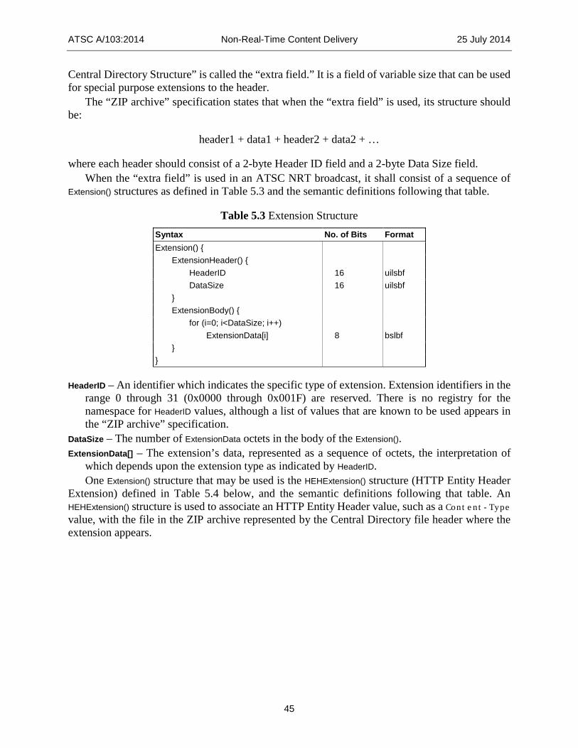
ATSC A/103:2014 Non-Real-Time Content Delivery 25 July 2014
45
Central Directory Structure” is called the “extra field.” It is a field of variable size that can be used for special purpose extensions to the header.
The “ZIP archive” specification states that when the “extra field” is used, its structure should be:
header1 + data1 + header2 + data2 + …
where each header should consist of a 2-byte Header ID field and a 2-byte Data Size field. When the “extra field” is used in an ATSC NRT broadcast, it shall consist of a sequence of
Extension() structures as defined in Table 5.3 and the semantic definitions following that table.
Table 5.3 Extension Structure Syntax No. of Bits Format Extension() { ExtensionHeader() { HeaderID 16 uilsbf DataSize 16 uilsbf } ExtensionBody() { for (i=0; i<DataSize; i++) ExtensionData[i] 8 bslbf } }
HeaderID – An identifier which indicates the specific type of extension. Extension identifiers in the range 0 through 31 (0x0000 through 0x001F) are reserved. There is no registry for the namespace for HeaderID values, although a list of values that are known to be used appears in the “ZIP archive” specification.
DataSize – The number of ExtensionData octets in the body of the Extension(). ExtensionData[] – The extension’s data, represented as a sequence of octets, the interpretation of
which depends upon the extension type as indicated by HeaderID. One Extension() structure that may be used is the HEHExtension() structure (HTTP Entity Header
Extension) defined in Table 5.4 below, and the semantic definitions following that table. An HEHExtension() structure is used to associate an HTTP Entity Header value, such as a Content-Type value, with the file in the ZIP archive represented by the Central Directory file header where the extension appears.
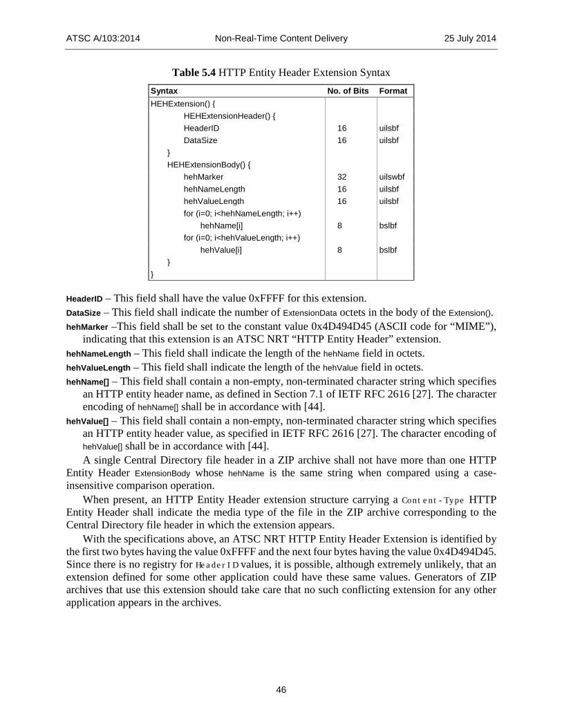
ATSC A/103:2014 Non-Real-Time Content Delivery 25 July 2014
46
Table 5.4 HTTP Entity Header Extension Syntax Syntax No. of Bits Format HEHExtension() { HEHExtensionHeader() { HeaderID 16 uilsbf DataSize 16 uilsbf } HEHExtensionBody() { hehMarker 32 uilswbf hehNameLength 16 uilsbf hehValueLength 16 uilsbf for (i=0; i<hehNameLength; i++) hehName[i] 8 bslbf for (i=0; i<hehValueLength; i++) hehValue[i] 8 bslbf } }
HeaderID – This field shall have the value 0xFFFF for this extension. DataSize – This field shall indicate the number of ExtensionData octets in the body of the Extension(). hehMarker –This field shall be set to the constant value 0x4D494D45 (ASCII code for “MIME”),
indicating that this extension is an ATSC NRT “HTTP Entity Header” extension. hehNameLength – This field shall indicate the length of the hehName field in octets. hehValueLength – This field shall indicate the length of the hehValue field in octets. hehName[] – This field shall contain a non-empty, non-terminated character string which specifies
an HTTP entity header name, as defined in Section 7.1 of IETF RFC 2616 [27]. The character encoding of hehName[] shall be in accordance with [44].
hehValue[] – This field shall contain a non-empty, non-terminated character string which specifies an HTTP entity header value, as specified in IETF RFC 2616 [27]. The character encoding of hehValue[] shall be in accordance with [44]. A single Central Directory file header in a ZIP archive shall not have more than one HTTP
Entity Header ExtensionBody whose hehName is the same string when compared using a case-insensitive comparison operation.
When present, an HTTP Entity Header extension structure carrying a Content-Type HTTP Entity Header shall indicate the media type of the file in the ZIP archive corresponding to the Central Directory file header in which the extension appears.
With the specifications above, an ATSC NRT HTTP Entity Header Extension is identified by the first two bytes having the value 0xFFFF and the next four bytes having the value 0x4D494D45. Since there is no registry for HeaderID values, it is possible, although extremely unlikely, that an extension defined for some other application could have these same values. Generators of ZIP archives that use this extension should take care that no such conflicting extension for any other application appears in the archives.
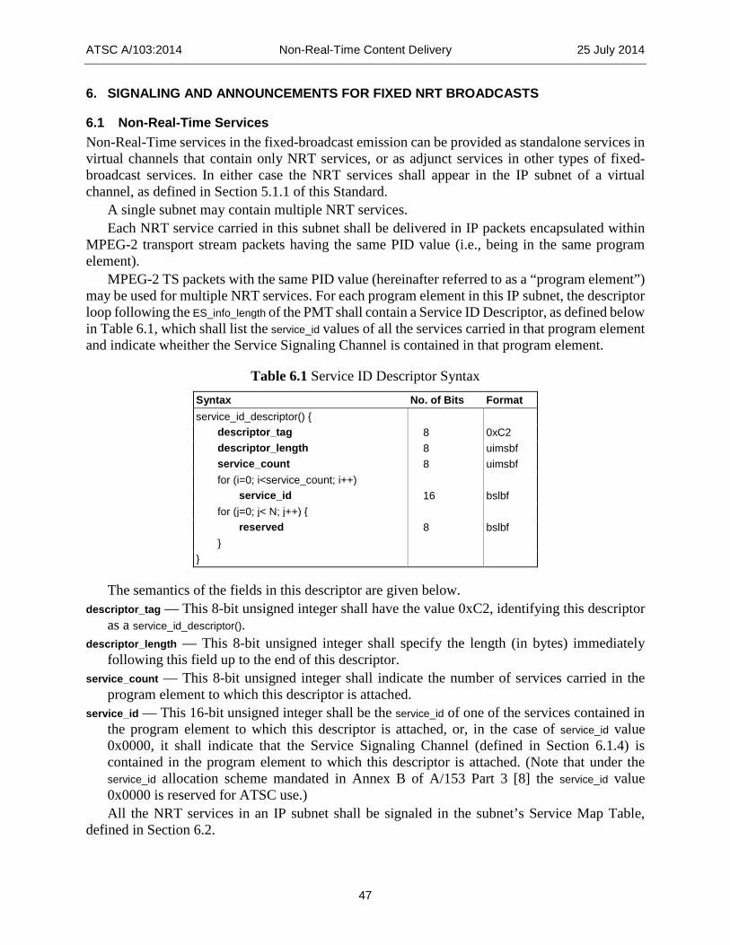
ATSC A/103:2014 Non-Real-Time Content Delivery 25 July 2014
47
6. SIGNALING AND ANNOUNCEMENTS FOR FIXED NRT BROADCASTS
6.1 Non-Real-Time Services Non-Real-Time services in the fixed-broadcast emission can be provided as standalone services in virtual channels that contain only NRT services, or as adjunct services in other types of fixed-broadcast services. In either case the NRT services shall appear in the IP subnet of a virtual channel, as defined in Section 5.1.1 of this Standard.
A single subnet may contain multiple NRT services. Each NRT service carried in this subnet shall be delivered in IP packets encapsulated within
MPEG-2 transport stream packets having the same PID value (i.e., being in the same program element).
MPEG-2 TS packets with the same PID value (hereinafter referred to as a “program element”) may be used for multiple NRT services. For each program element in this IP subnet, the descriptor loop following the ES_info_length of the PMT shall contain a Service ID Descriptor, as defined below in Table 6.1, which shall list the service_id values of all the services carried in that program element and indicate wheither the Service Signaling Channel is contained in that program element.
Table 6.1 Service ID Descriptor Syntax Syntax No. of Bits Format service_id_descriptor() { descriptor_tag 8 0xC2 descriptor_length 8 uimsbf service_count 8 uimsbf for (i=0; i<service_count; i++) service_id 16 bslbf for (j=0; j< N; j++) { reserved 8 bslbf } }
The semantics of the fields in this descriptor are given below. descriptor_tag — This 8-bit unsigned integer shall have the value 0xC2, identifying this descriptor
as a service_id_descriptor(). descriptor_length — This 8-bit unsigned integer shall specify the length (in bytes) immediately
following this field up to the end of this descriptor. service_count — This 8-bit unsigned integer shall indicate the number of services carried in the
program element to which this descriptor is attached. service_id — This 16-bit unsigned integer shall be the service_id of one of the services contained in
the program element to which this descriptor is attached, or, in the case of service_id value 0x0000, it shall indicate that the Service Signaling Channel (defined in Section 6.1.4) is contained in the program element to which this descriptor is attached. (Note that under the service_id allocation scheme mandated in Annex B of A/153 Part 3 [8] the service_id value 0x0000 is reserved for ATSC use.) All the NRT services in an IP subnet shall be signaled in the subnet’s Service Map Table,
defined in Section 6.2.

ATSC A/103:2014 Non-Real-Time Content Delivery 25 July 2014
48
6.1.1 Standalone NRT Services Fixed-broadcast virtual channels containing exclusively non-real-time elements shall be identified by the value 0x08 in the field service_type in the Virtual Channel Table (terrestrial_virtual_channel_table_section() or cable_virtual_channel_table_section()) (see A/65 [14]).
Virtual channels associated with this type of service carry only file-based content, such as A/V clips, full-length programming, and textual/graphics information. 6.1.2 Adjunct NRT Services NRT services can be present within other types of virtual channels (i.e., virtual channels with service_type other than 0x08). Such services are called adjunct NRT services.
Adjunct services are delivered in an IP subnet associated with the MPEG-2 program (see Section 5.1.1). The Service Signaling Channel within the IP subnet delivers the SMT, the NRT-IT instances, and optionally the TFT instances. The use of the SMT in the fixed broadcast is defined in Section 6.2 below; the use of the NRT-IT is found in Section 6.3 below’ and the use of the TFT is defined in Section 6.4 below.
When an adjunct NRT service is included with a linear TV service (e.g. a virtual channel with service_type value 0x02), the receiver is expected to render the audio and video elementary stream components and then render any visual NRT-related content over the video. The following table illustrates some scenarios involving different NRT consumption models (as identified in the NRT Service Descriptor; see Section 8.2).
Table 6.2 Adjunct Services for Linear TV Service – Expected Receiver Behavior consumption_model value Expected Receiver Behavior
0x01 Browse & Download
Undefined. Not expected to be used. Browse & Download involves a UI defined by the receiver manufacturer, which would often take up the full screen.
0x02 Portal The content associated with the NRT service is rendered on top of video, which (depending on the nature of the NRT content) may or may not be visible. The NRT service content may or may not be related to the program. Not expected to be used, since the NRT content would impact viewing and the user would likely wish to turn it off.
0x03 Push Undefined. Not expected to be used, since Push involves a UI defined by the receiver manufacturer which would often take up the full screen.
0x04 Triggered This consumption model is the one that is expressly designed for use with linear TV services. It allows the addition of interactive content related to the program, and to events synchronized to actions within the program.
0x06 Push Scripted Undefined. 0x05 Portal Scripted Not expected to be used. See Portal.
0x07 EPG Undefined. Not expected to be used, since content items delivered in an NRT service with EPG consumption model are not intended to be presented directly to viewers. They are intended to be presented only as components of the receiver’s native EPG display.
Where the expected receiver behavior is indicated as “undefined” in Table 6.2, service providers may expect unpredictable (and therefore likely undesirable) user experiences to result. Use of such consumption models with linear TV is strongly discouraged. As shown, the expected and preferred NRT adjunct service accompanying linear TV is defined by the Triggered consumption model. 6.1.3 NRT Protocol Version Identification All the components of a given NRT service in a fixed-broadcast emission shall conform to the same major/minor protocol version of the NRT Standard. This major/minor protocol version is

ATSC A/103:2014 Non-Real-Time Content Delivery 25 July 2014
49
called the NRT protocol version of the service. A change in the major version level indicates a non-backward-compatible level of change. A change in the minor version level, provided the major version level remains the same, indicates a backward-compatible level of change.
If all the NRT services in the IP subnet of a virtual channel conform to the same version of the NRT standard, a Protocol Version Descriptor with protocol_identifier value 0x03 shall appear in the subnet_level descriptor loop of the SMT (as described in Section 6.2.1) to indicate the common NRT protocol version of all the NRT services. If the IP subnet of the virtual channel contains NRT services of different protocol versions, Protocol Version Descriptors with protocol_identifier value 0x03 shall appear in the service level descriptor loops for those services in the SMT to identify the individual NRT protocol versions of those services.
There is an expectation that receivers will not offer to the user NRT services labeled with a value of major_protocol_version higher than that for which the receiver was built to support. Receivers are not expected to use minor_protocol_version as a basis for not offering a given service to the user. Receivers are expected to use minor_protocol_version to determine whether the transmission includes data elements defined in later versions of the Standard1. 6.1.4 Service Signaling Channel As specified in Section 5.1.1, an IP subnet carrying NRT components contains a Service Signaling Channel (SSC), defined as those IP packets in the subnet with IP multicast address 224.0.23.60 and UDP port 4937. This SSC shall contain the following signaling tables:
• The Service Map Table (SMT), as defined in Section 6.2 of this Standard, and • One or more Non-Real-Time Information Tables (NRT-IT), as defined in Section 6.3 of
this Standard. The following optional tables are defined to be part of the SSC, when sent:
• One or more Text Fragment Tables (TFT), as defined in Section 6.4 of this Standard, • One or more Targeting Criterion Tables, as defined in Section 9.4 of this Standard, and • Purchase information tables, as defined in Section 6.5 of this Standard. All IP packets of the Service Signaling Channel for a virtual channel shall appear in a single
program element of the virtual channel. That program element may contain one or more services along with the Service Signaling Channel. No other IP packets shall appear in the SSC when the major_protocol_version field of the SMT is set to 0x01. Receivers are expected to ignore any unknown structures found in the SSC. 6.1.5 Structure of SSC Tables The Service Signaling Channel (SSC) tables defined by this standard are modeled after the Generic Table Format defined in the ATSC Mobile DTV standard, Part 3 [8], Section 7.1 (which is in turn modeled after the MPEG-2 private_section generic syntax defined in the MPEG-2 Systems standard [57], sections 2.4.4.10 and 2.4.4.11). However, the SSC table sections defined in this standard differ from the Generic Table Format in that in some cases the definition of “table” used for the purposes of versioning and section numbering is based on the values of a larger set of fields than just the table_id and table_id_extension. The definition of each table in this standard includes a
1 A field defined in the current version of this Standard as “reserved” may be defined in a future
version as conveying a certain meaning dependent upon the value of minor_protocol_version. A field may, for example, be defined as reserved for minor_protocol_version values 0 and 1, and given a specific meaning beginning at minor_protocol_version 2.
ATSC A/103:2014 Non-Real-Time Content Delivery 25 July 2014
50
specification of the set of fields used to identify a “table” for versioning and section numbering purposes.
Fields in SSC table sections that have the same names as fields in the Generic Table Format shall have the same semantics as those fields in the Generic Table Format, unless otherwise redefined in the semantic definitions following the syntax definition for the SSC table section.
Except where indicated otherwise, any SSC table field that is identified as a text string shall be UTF-8 [44] encoded.
6.2 Service Map Table (SMT) The Service Map Table (SMT) contains service-level attributes for NRT Services carried in the fixed-broadcast Transport Stream. The structure defined hereinunder is signaled by the Protocol Version Descriptor with the protocol_identifier field set to 0x03, major_protocol_version field set to 0x01 and minor_protocol_version field set to 0x01. The bit stream syntax and semantics of this SMT shall be identical to the Service Map Table for M/H services defined in A/153 Part 3 [8] Section 7.3, with the following exceptions:
• References to “M/H Services” shall be considered references to “IP Subnet Services”. • The concept of ensemble is inapplicable to fixed-broadcast transport. The
multi_ensemble_service field shall be reserved and set to ‘11’ for fixed-broadcast use of the SMT.
• The ensemble_id field shall be renamed subnet_id for fixed broadcasts, with the following semantics: subnet_id – This 8-bit unsigned integer shall indicate the IP subnet associated with this
service signaling channel. The scope of subnet_id shall be the full main broadcast Transport Stream. If NRT services are present in both ‘fixed’ and ‘mobile’ streams the value in the subnet_id field (in a fixed stream) should be different from the value in the ensemble_id field (in any mobile stream). Receivers should retain the separate identity of each source.
• The SMT_MH_protocol_version field shall be renamed to SMT_protocol_version for fixed broadcasts, with the following semantics: SMT_protocol_version – The most significant 4 bits of this 8-bit unsigned integer shall indicate
the major version number of the SMT, and the least significant 4 bits shall indicate the minor version number of the SMT. For the table defined in this standard the major version number shall be “1”, and the minor version number shall be “0”.
• The num_ensemble_level_descriptors field shall be renamed num_subnet_level_descriptors for fixed broadcasts, with the following semantics: num_subnet_level_descriptors – This 4-bit unsigned integer number in the range 0 to 15 shall
indicate the number of subnet-level descriptors to follow. • The ensemble_level_descriptor() field shall be renamed subnet_level_descriptor() for fixed
broadcasts, with the following semantics: subnet_level_descriptor() – Zero or more descriptors providing additional information
pertaining to the NRT services carried in this IP subnet may be included. • The following fields shall be renamed as indicated:
“MH_service_id” renamed to “service_id” “MH_service_status” renamed to “service_status”

ATSC A/103:2014 Non-Real-Time Content Delivery 25 July 2014
51
“short_MH_service_name_length” renamed to “short_service_name_length” “short_MH_service_name” renamed to “short_service_name” “MH_service_category” renamed to “service_category” “num_MH_service_level_descriptors” renamed to “”num_service_level_descriptors” “MH_service_level_descriptor()” renamed to “service_level_descriptor()”
• For NRT services the service_category field shall be set to 0x0E. The following provisions apply to the delivery of the SMT in the Service Signaling Channel: • For each IP subnet, SMT sections describing all the NRT services of that IP subnet shall
be included in that IP subnet. • Each SMT section shall be contained within a single IP multicast datagram. • Different SMT sections shall be contained in different datagrams. • The repetition rate of the SMT should be set by the broadcaster to a rate commensurate
with the desired user experience.2 • The SMT sections for each IP subnet shall be differentiated via the subnet_id included in the
section header. Any changes in the contents of the SMT (which would reflect changes in the NRT Service
line-up or properties) shall be conveyed in a new SMT carrying an incremented version number. The information contained in the SMT includes service acquisition information for the IP streams that form each NRT service, such as destination multicast IP address and destination UDP port number. The set of SMT sections in a given IP subnet shall include information for all NRT Services that are carried (wholly or partially) in that IP subnet. 6.2.1 Subnet-Level SMT Descriptors Subnet level descriptors may appear within the SMT in the location indicated by the field name subnet_level_descriptor() to describe attributes common to the entire subnet.
When all the services of service_category 0x0E in the subnet are of the same NRT protocol version, this subnet-level descriptor loop shall contain a Protocol Version Descriptor with protocol_identifier value 0x03 and major/minor_protocol_version fields indicating the NRT protocol version of the NRT services.
Other descriptors may also appear in the subnet level descriptor loop. 6.2.2 Service-Level SMT Descriptors Service level descriptors may appear within the SMT in the location indicated by the field name service_level_descriptor() to describe attributes of a given NRT service. Service level descriptors defined for use in the SMT are listed in Table 6.3. Certain service-level descriptors shall always be present, as indicated below and in Table 6.3.
For each NRT service (those identified by service_category value 0x0E), the SMT shall include one NRT Service Descriptor and one or more Capabilities Descriptors at the service level. If the services of service_category 0x0E in the subnet are not all of the same NRT protocol version, then the service level descriptor loop for each service in the SMT shall contain a Protocol Version Descriptor with protocol_identifier value 0x03 and major/minor protocol version fields indicating the NRT protocol version of that service.
2 The rate should be set high enough that most users do not encounter what looks like an
unresponsive or vacant channel when accessing the NRT service.
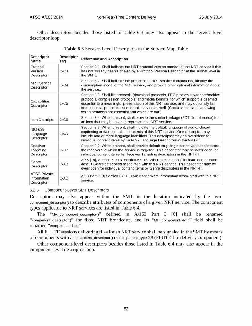
ATSC A/103:2014 Non-Real-Time Content Delivery 25 July 2014
52
Other descriptors besides those listed in Table 6.3 may also appear in the service level descriptor loop.
Table 6.3 Service-Level Descriptors in the Service Map Table Descriptor Name
Descriptor Tag Reference and Description
Protocol Version Descriptor
0xC3 Section 8.1. Shall indicate the NRT protocol version number of the NRT service if that has not already been signaled by a Protocol Version Descriptor at the subnet level in the SMT..
NRT Service Descriptor 0xC4
Section 8.2. Shall indicate the presence of NRT service components, identify the consumption model of the NRT service, and provide other optional information about the service..
Capabilities Descriptor 0xC5
Section 8.3. Shall list protocols (download protocols, FEC protocols, wrapper/archive protocols, compression protocols, and media formats) for which support is deemed essential to a meaningful presentation of this NRT service, and may optionally list non-essential protocols used for this service as well. (Contains indicators showing which protocols are essential and which are not.)
Icon Descriptor 0xC6 Section 8.4. When present, shall provide the content-linkage (FDT file reference) for an icon that may be used to represent the NRT service.
ISO-639 Language Descriptor
0x0A
Section 8.5. When present, shall indicate the default language of audio, closed captioning and/or textual components of this NRT service. One descriptor may include one or more language identifiers. This descriptor may be overridden for individual content items by ISO-639 Language Descriptors in the NRT-IT.
Receiver Targeting Descriptor
0xC7 Section 9.2. When present, shall provide default targeting criterion values to indicate the receivers to which the service is targeted. This descriptor may be overridden for individual content items by Receiver Targeting descriptors in the NRT-IT.
Genre Descriptor 0xAB
A/65 [14], Section 6.9.13, Section 6.9.13. When present, shall indicate one or more default Genre categories associated with this NRT service. This descriptor may be overridden for individual content items by Genre descriptors in the NRT-IT.
ATSC Private Information Descriptor
0xAD A/53 Part 3 [3] Section 6.8.4. Usable for private information associated with this NRT service.
6.2.3 Component-Level SMT Descriptors Descriptors may also appear within the SMT in the location indicated by the term component_descriptor() to describe attributes of components of a given NRT service. The component types applicable to NRT services are listed in Table 6.4.
The “MH_component_descriptor()” defined in A/153 Part 3 [8] shall be renamed “component_descriptor()” for fixed NRT broadcasts, and its “MH_component_data” field shall be renamed “component_data.”
All FLUTE sessions delivering files for an NRT service shall be signaled in the SMT by means of components with a component_descriptor() of component_type 38 (FLUTE file delivery component).
Other component-level descriptors besides those listed in Table 6.4 may also appear in the component-level descriptor loop.

ATSC A/103:2014 Non-Real-Time Content Delivery 25 July 2014
53
Table 6.4 Component-Level Descriptors in the Service Map Table Descriptor Name
Descriptor Tag Reference and Description
Component Descriptor 0xBC
The following component types are applicable for use with NRT services. The syntax and semantics of the FLUTE file delivery component is as specified in A/153 Part 3 [8] Section 7.8.1, extended as specified in Section 8/6 of this Standard. component type Meaning 38 FLUTE file delivery component.
6.3 Non-Real-Time Information Table (NRT-IT) The Non-Real-Time Information Table (NRT-IT) contains information describing content items available for download to storage in the receiving device. The information provided in the NRT-IT includes the title of the content item (for example, the name of the program available for download), the times during which the content item is to be made available for download, and information such as content advisories, availability of caption services, content identification, and other metadata.
One content item may consist of one or more files. For example, it could consist of a collection of audio/video clips, together with an HTML page which can be presented to a viewer to allow the viewer to select clips to play.
There shall be one NRT-IT for each NRT service (service with service_category value 0x0E). Each NRT-IT may consist of multiple NRT-IT Instances.
Unlike the PSIP EIT [14], in which each instance corresponds to a 3-hour time slot, an NRT-IT Instance can include data corresponding to an arbitrarily defined time period, or it can describe NRT content starting at a specified time and extending into the indefinite future. Each NRT-IT Instance indicates the start time of the period (time_span_start) it covers and the length of the period (time_span_length) it covers (which may be indefinite).
The time periods of NRT-IT Instances for the same NRT service shall not overlap. Each NRT-IT instance may be segmented into as many as 256 sections. One section may
contain information for multiple content items, but the information for any given content item shall not be segmented and put into two or more sections.
A content item belonging to a service shall be eligible to be included in an NRT-IT Instance for that service if any of the time periods when it is scheduled to be made available in the broadcast overlap the time period covered by the NRT-IT Instance. When a content item is eligible to be included in multiple NRT-IT instances, it shall be included only in the first of those NRT-IT Instances.
When the NRT-IT instance that includes such a content item expires, if the content item is still available, it will need to be placed into the next NRT-IT instance for which it is eligible.
Service providers need to be aware that for many types of NRT services, especially “browse and download” services with relatively large content items, it is very important to announce the content items well ahead of time, so that the user can request the desired content items and arrange for the receiving device to be “tuned” to the service during the time intervals when they are being transmitted.
Content item descriptions shall be placed within the NRT_information_table_section() in the order of their first availability. Therefore, when last_section_number is greater than zero (meaning the NRT-IT is delivered in multiple sections), for sections other than the first (sections for which the value of section_number is greater than zero), all the content item descriptions within a given section shall

ATSC A/103:2014 Non-Real-Time Content Delivery 25 July 2014
54
have first availability times that are greater than or equal to all first availability times of content item descriptions in the immediately preceding section (the section whose value of section_number is one lower than the given section). The contents of the fields and descriptors for each content item shall be accurate representations of the known information about the content item at the time the content item instance is created and shall be updated if more accurate information becomes available.
The Non-Real-Time Information Table is carried in table sections with table_id 0xDF. The IP multicast packets carrying the NRT-IT Instance sections for a service shall be in the
Service Signaling Channel of the IP subnet carrying the service; i.e., their IP multicast address and port shall match the address and port for the SSC, as specified in Section 6.1.4 of this Standard.
The following constraints apply to the IP packets carrying the NRT-IT sections: • There shall be no more than one NRT-IT section in a single IP packet. • Different NRT-IT sections shall be in different IP packets. The NRT_information_table_section() is modeled after the MH_service_signaling_table_section() defined
in A/153 Part 3 [8], Section 7.1. Unless otherwise defined below, identically-named fields in the NRT_information_table_section() shall be as defined as in the MH_service_signaling_table_section() in A/153 Part 3 [8], Section 7.1. The bit stream syntax for the Non-Real-Time Information Table sections shall be as shown in Table 6.5. The semantics of the fields in this Table are specified immediately after the Table.
Table 6.5 Bit Stream Syntax for the Non-Real-Time Information Table (next page)
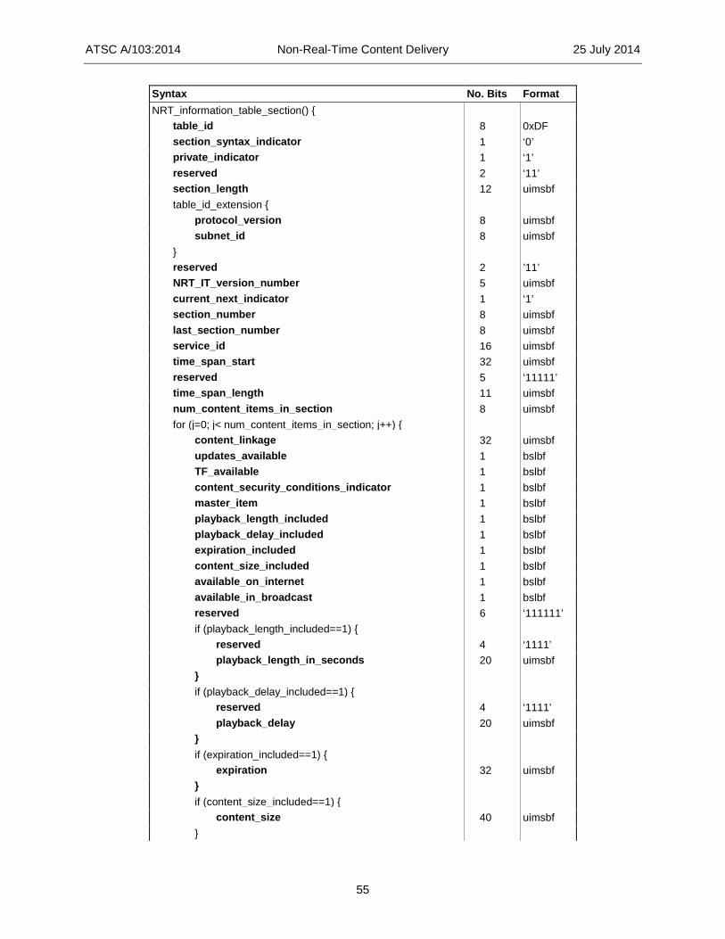
ATSC A/103:2014 Non-Real-Time Content Delivery 25 July 2014
55
Syntax No. Bits Format NRT_information_table_section() { table_id 8 0xDF section_syntax_indicator 1 ‘0’ private_indicator 1 ‘1’ reserved 2 ‘11’ section_length 12 uimsbf table_id_extension { protocol_version 8 uimsbf subnet_id 8 uimsbf } reserved 2 ’11’ NRT_IT_version_number 5 uimsbf current_next_indicator 1 ‘1’ section_number 8 uimsbf last_section_number 8 uimsbf service_id 16 uimsbf time_span_start 32 uimsbf reserved 5 ‘11111’ time_span_length 11 uimsbf num_content_items_in_section 8 uimsbf for (j=0; j< num_content_items_in_section; j++) { content_linkage 32 uimsbf updates_available 1 bslbf TF_available 1 bslbf content_security_conditions_indicator 1 bslbf master_item 1 bslbf playback_length_included 1 bslbf playback_delay_included 1 bslbf expiration_included 1 bslbf content_size_included 1 bslbf available_on_internet 1 bslbf available_in_broadcast 1 bslbf reserved 6 ‘111111’ if (playback_length_included==1) { reserved 4 ‘1111’ playback_length_in_seconds 20 uimsbf } if (playback_delay_included==1) { reserved 4 ‘1111’ playback_delay 20 uimsbf } if (expiration_included==1) { expiration 32 uimsbf } if (content_size_included==1) { content_size 40 uimsbf }

ATSC A/103:2014 Non-Real-Time Content Delivery 25 July 2014
56
content_name_length 8 uimsbf content_name_text() var num_content_descriptors 8 uimsbf for (i=0; i<num_content_descriptors; i++) { content_descriptor() var } } num_descriptors 8 uimsbf for (i=0; i<num_descriptors; i++) { descriptor() var } }
table_id – This 8-bit field shall be set to 0xDF to identify this table section as belonging to the Non-Real-Time Information Table.
protocol_version – This 8-bit unsigned integer field shall be set to 0x10, where the high order 4 bits indicate the major version number and the low order 4 bits indicate the minor version number. The function of protocol_version is to allow, in the future, this table type to carry parameters that might be structured differently than those defined in the current protocol. New values of protocol_version may be used by future versions of this standard to indicate structurally different tables.
subnet_id – This 8-bit unsigned integer shall indicate the IP subnet associated with this service signaling channel.
NRT_IT_version_number – This 5-bit field shall indicate the version number of this entire NRT-IT instance. Each NRT-IT instance shall be identified by the combination of the values in service_id, table_id, table_id_extension, and time_span_start. The version number shall be incremented by 1 modulo 32 when any field in the NRT-IT instance changes.
current_next_indicator – This 1-bit indicator shall always be set to ‘1’ for NRT-IT sections; the NRT-IT sent is always currently applicable.
section_number – This 8-bit field shall give the section number of this NRT-IT Table Instance section, where the NRT-IT Table Instance is identified by the combination of table_id, table_id_extension, service_id and time_span_start fields. The section_number of the first section in an NRT-IT Table Instance shall be 0x00. The section_number shall be incremented by 1 with each additional section in the NRT-IT Table Instance.
last_section_number – This 8-bit field shall give the number of the last section (i.e., the section with the highest section_number) of the NRT-IT Table Instance of which this section is a part.
service_id – This 16-bit field shall specify the service_id associated with the NRT service offering the content items described in this section.
time_span_start – This 32-bit unsigned integer shall represent the start of the time span covered by this instance of the NRT-IT, expressed as the number of GPS seconds since 00:00:00 UTC, 6 January 1980. The time of day of time_span_start shall be aligned to minute 00 of the hour. The value zero for time_span_start shall indicate the time period covered by his NRT-IT instance began in the indefinite past. The value of time_span_start shall be the same for each section of a multi-sectioned NRT-IT instance. The values of time_span_start and time_span_length shall be set such that the specified time span does not overlap with any other NRT-IT instance in this IP subnet.

ATSC A/103:2014 Non-Real-Time Content Delivery 25 July 2014
57
time_span_length – This 11-bit unsigned integer field in the range 0 to 1440 shall indicate the number of minutes, starting at the time indicated by time_span_start, covered by this instance of the NRT-IT. Once established, the value of time_span_length for a given value of time_span_start shall not change. A value of time_span_length of zero shall mean this NRT-IT instance covers all time starting at time_span_start into the indefinite future. If the value of time_span_start is zero, time_span_length shall have no meaning and shall be set to zero. The value of time_span_length shall be the same for each section of a multi-sectioned NRT-IT instance. The values of time_span_start and time_span length shall be set such that the specified time span does not overlap with any other NRT-IT instance in this IP subnet.
num_content_items_in_section – This 8-bit unsigned integer field shall indicate the number of content items described in this NRT-IT section.
content_linkage – This 32-bit unsigned integer field in the range 0x00000001 to 0xFFFFFFFF shall specify the identification number of the content item described. Value 0x00000000 shall not be used. The content_linkage performs two linkage functions: it links metadata in the NRT-IT to one or more files in the FLUTE FDT associated with this NRT content item; it also forms the TF_id (identifier for Text Fragment in Text Fragment Table). Each file associated with the content item shall have a FLUTE FDT content linkage tag matching the value of this content_linkage field (where “content linkage tag” is defined in Section 5.3). For a particular NRT service, the value of content_linkage shall be unique over the set of linkage values for all content items and icons in the service from the time when the content item or icon descriptor first appears in the NRT-IT or any of its files appear in FLUTE FDT instances to the time when the content item or icon descriptor no longer appears in the NRT-IT and none of its files appear in FLUTE FDT instances (taking into account the “Expires” attribute of the FLUTE FDT instances).
updates_available – This Boolean flag shall specify, when set to ‘1,’ that the referenced content item(s) will be updated periodically: for content items delivered in FLUTE sessions, receiving devices are expected to monitor for changes the TOI associated with each file associated with the given value of content_linkage. When the updates_available flag is set to ‘0’, updates are not expected to be provided for the associated content item(s), and receivers are not expected to look for them.
TF_available – This Boolean flag shall specify, when set to ‘1’ that a Text Fragment is present in a Text Fragment Table in the service signaling channel. When the flag is set to ‘0,’ no Text Fragment is included in the service signaling channel for this content item.
content_security_conditions_indicator – A 1-bit field that indicates, whether or not content protection is applied to at least one of the files that constitute this content item. When set to ‘0’, the field shall indicate that all the files that constitute this content item are unprotected. When set to ‘1’, the field shall indicate that one or more of the files that constitute this content item are protected.
master_item – This Boolean flag shall indicate, when set to ‘1’, that the content item is the “master” content item. A “master” content item is the content item to be launched when the service is selected. Setting this flag to ‘0’ shall indicate the content item is not a “master” content item. Only one content item in a given service shall be indicated as a “master” content item.
playback_length_included – This Boolean flag shall indicate, when set to ‘1,’ that the playback_length_in_seconds field is present in this iteration of the “for” loop. Setting this flag to ‘0’ shall indicate the playback_length_in_seconds field is not present in this iteration of the “for” loop.

ATSC A/103:2014 Non-Real-Time Content Delivery 25 July 2014
58
playback_delay_included — This Boolean flag shall indicate, when set to ‘1,’ that the playback_delay field is present in this iteration of the “for” loop. Setting this flag to ‘0’ shall indicate the playback_delay field is not present in this iteration of the “for” loop.
expiration_included — This Boolean flag shall indicate, when set to ‘1,’ that the expiration field is present in this iteration of the “for” loop. Setting this flag to ‘0’ shall indicate the expiration field is not present in this iteration of the “for” loop.
content_size_included – This Boolean flag shall indicate, when set to ‘1,’ that the content_size field is present in this iteration of the “for” loop. Setting this flag to ‘0’ shall indicate the content_size field is not present in this iteration of the “for” loop.
available_on_internet – When this 1-bit field is set to ‘1’, it shall indicate that all the files that constitute this content item are available over an Internet connection. When this field is set to ‘0’, it shall convey no information about whether or not the files that constitute this content item are available over an Internet connection.
available_in_broadcast – When this 1-bit field is set to ‘1’, it shall indicate that all the files that constitute this content item are available in the broadcast stream, in a file delivery component of this NRT service. When this 1-bit field is set to ‘0’, it shall convey no information about whether or not the files that constitute this content item are available in the broadcast stream.
playback_length_in_seconds – This 20-bit unsigned integer quantity shall specify the duration of playback of the content, in seconds. For content not intended to be presented on a timeline, the value zero shall be used. For content that includes audio or audio/video content, the playback_length_in_seconds shall indicate the playback length of the audio or audio/video content.
playback_delay – A 20-bit unsigned integer count of the number of seconds following reception of the first byte of the associated content the receiver shall wait before playback may start, while buffering the incoming stream. A value of zero shall indicate playback may commence immediately. When playback_delay is not provided, the receiver is expected to retrieve the complete file or file set prior to playback.
expiration – This 32-bit unsigned integer shall represent the expiration time of the content, expressed as the number of GPS seconds since 00:00:00 UTC, 6 January 1980. Following expiration, the content should be deleted from memory. If an expiration time is not specified, receivers are expected to use methods of their own choosing to manage memory resources.
content_size – When present, this 40-bit unsigned integer quantity shall represent the total size in bytes of the content item or items. This item is used by the receiving device to determine if enough memory is available to store it before downloading is attempted. The content_size field shall be present when content_size_included is set to ‘1’ and absent otherwise. When content_size is not present in a given iteration of the “for” loop, the size of the content described in that iteration shall be the value specified in the default_content_size field in the NRT_service_descriptor() in the SMT, if that field ispresent in the descriptor.
content_name_length – This 8-bit unsigned integer field shall specify the length (in bytes) of the content_name_text().
content_name_text() – This field shall specify the content item title in the format of a multiple string structure (see A/65 [14] Section 6.10).
num_content_descriptors – This 8-bit unsigned integer field shall indicate the total number of descriptors in the descriptor list that follows.

ATSC A/103:2014 Non-Real-Time Content Delivery 25 July 2014
59
content_descriptor() – One or more descriptors in standard MPEG-2 descriptor format (tag, length, data) may appear in this content item level descriptor loop to provide information about individual content items.
num_descriptors – An 8-bit unsigned integer number that indicates the number of descriptors (if any) to follow.
descriptor() – Zero or more descriptors in standard MPEG-2 descriptor format (tag, length, data) may appear in this NRT-IT level descriptor loop to provide information common to all the NRT content described in this NRT_information_table_section(). No descriptors are currently defined for the NRT-IT level descriptor loop. However, it is not
forbidden for descriptors to appear there. Table 6.6 below lists some content-level descriptors usable in the NRT-IT. The presence of
some descriptors is mandatory, as indicated in the referenced sections where the descriptors are defined.
Other descriptors besides those in Table 6.6 may appear in the content item level descriptor loop.
Table 6.6 Content-Level Descriptors in the NRT-IT
Descriptor Name Descriptor Tag Reference and Description
Time Slot Descriptor 0xC8 Section 8.7. Shall indicate the time(s) the associated content is scheduled to be
made available in the digital transport.
Capabilities Descriptor 0xC5
Section 8.2. When present, shall list additional protocols (download protocols, FEC protocols, wrapper/archive protocols, compression protocols, and media formats), beyond those already listed in the service level Capabilities Descriptor, for which support is deemed essential to a meaningful presentation of this NRT content item, and may optionally list additional non-essential protocols used for this content item as well. (Contains indicators showing which protocols are essential and which are not.)
Internet Location Descriptor 0xC9 Section 8.8. When present, shall provide optional URLs for Internet-based access
to file(s) in the content item.
Icon Descriptor 0xC6 Section 8.4. When present, shall provide the content-linkage (FDT file reference) for an icon that may be used to represent the NRT content item.
ISO-639 Language Descriptor 0x0A Section 8.5. When present, shall indicate the language or languages of audio
and/or textual components of the content item.
Content Labeling Descriptor 0x36
A/57 [12] and ISO/IEC 13818-1 [57] Section 2.6.56. When present, shall associate the content item with content labeling metadata. Use of ISAN in this descriptor is strongly recommended when the content item contains a single audio/video component.
Caption Service Descriptor 0x86 A/65[14] Section 6.9.2. When present, shall provide caption service information
pertinent to the content item.
Content Advisory Descriptor 0x87
A/65 [14] Section 6.9.3. Only this descriptor, or its absence, shall determine the content advisory ratings for the content item. Note: Implementers are advised that CFF files are permitted to have metadata fields to convey elements of rating data which should be ignored. Broadcasters should not attempt to populate these fields when creating content files.
Genre Descriptor 0xAB A/65 [14] Section 6.9.13. When present, shall indicate one or more Genre categories associated with the content item.
Receiver Targeting Descriptor 0xC7 Section 9.2. When present, shall provide targeting criterion values to indicate the
receivers to which the content item is targeted. ATSC Private Information Descriptor
0xAD A/53 Part 3 [3] Section 6.8.4. Usable for private information associated with the content item.

ATSC A/103:2014 Non-Real-Time Content Delivery 25 July 2014
60
2D 3D Corresponding Content Descriptor
0xCD Section 8.11. When present, shall provide information necessary to access the corresponding 3D version of the 2D content item or vice versa.
6.4 Text Fragment Table (TFT) The Text Fragment Table (TFT) contains text fragments used to provide detailed descriptions of content items or services. The TFT carries a data structure supporting multiple languages, and thus it may represent descriptions in several different languages (each string corresponding to one language).
There is a TFT for each NRT service. Each TFT consists of one or more TFT Instances, which are in a one-to-one correspondence with the NRT-IT Instances for the service.
The Text Fragment Table is carried in private sections with table_id value 0xE1, and it obeys the syntax and semantics given below. Each text fragment is distinguished by its unique 32-bit TF_id.
The TFT sections shall be carried in IP packets within the Service Signaling Channel, which has been assigned by IANA to multicast IP address 224.0.23.60, port 4937.
The following constraints apply to the IP packets carrying the TFT sections. • There shall be no more than one TFT section in a single IP packet. • Different TFT sections shall be in different IP packets. Unless otherwise defined below, identically-named fields in the text_fragment_table_section() shall
be as defined as in the MH_service_signaling_table_section() defined in A/153 Part 3 [8], Section 7.1. The bit stream syntax for the Text Fragment Table shall be as shown in Table 6.7.

ATSC A/103:2014 Non-Real-Time Content Delivery 25 July 2014
61
Table 6.7 Bit Stream Syntax for the Text Fragment Table Syntax No. Bits Format text_fragment_table_section() { table_id 8 0xE1 section_syntax_indicator 1 ‘0’ private_indicator 1 ‘1’ reserved 2 ’11’ section_length 12 uimsbf table_id_extension { protocol_version 8 uimsbf subnet_id 8 uimsbf } reserved 2 ’11’ TFT_version_number 5 uimsbf current_next_indicator 1 ‘1’ section_number 8 uimsbf last_section_number 8 uimsbf service_id 16 uimsbf time_span_start 32 uimsbf reserved 5 ‘11111’ time_span_length 11 uimsbf num_fragments_in_section 8 uimsbf for (j=0; j< num_fragments_in_section; j++) { TF_id 32 uimsbf text_length 16 uimsbf text_fragment() var } }
table_id – This 8-bit field shall be set to 0xE1 to identify this table section as belonging to the Text Fragment Table.
section_length – This 12-bit unsigned integer field shall specify the number of remaining bytes of this table section immediately following this field. The value in this field shall not exceed 4093 (0xFFD).
protocol_version – This 8-bit unsigned integer field shall be set to 0x10, where the high order 4 bits indicate the major version number and the low order 4 bits indicate the minor version number. The function of protocol_version is to allow, in the future, this table type to carry parameters that may be structured differently than those defined in the current protocol. New values of protocol_version may be used by future versions of this standard to indicate structurally different tables.
subnet_id – This 8-bit unsigned integer shall indicate the IP subnet associated with this service signaling channel.
TF_version_number – This 5-bit field shall indicate the version number of the entire TFT instance, where a TFT instance shall be identified as the value of the combination of service_id, table_id, table_id_extension, and time_span_start field values. The version number shall be incremented by 1 modulo 32 when any field in the TFT instance changes.

ATSC A/103:2014 Non-Real-Time Content Delivery 25 July 2014
62
current_next_indicator – This 1-bit indicator shall always be set to ‘1’ for TFT sections; the TFT sent is always currently applicable.
section_number – This 8-bit field shall give the section number of this TFT instance section, where the TFT instance is identified by the combination of table_id, table_id_extension, service_id, and time_span_start fields. The section_number of the first section in a TFT instance shall be 0x00. The section_number shall be incremented by 1 with each additional section in the TFT Table instance.
last_section_number – This 8-bit field shall give the number of the last section (i.e., the section with the highest section_number) of the TFT instance of which this section is a part.
service_id – This 16-bit field shall specify the service_id associated with the service offering text fragments transported in this table section.
time_span_start – This 32-bit unsigned integer shall represent the start of the time span covered by this instance of the TFT, expressed as the number of GPS seconds since 00:00:00 UTC, 6 January 1980. The time of day of time_span_start shall be aligned to minute 00 of the hour. The value zero for time_span_start shall indicate the time period covered by his TFT instance began in the indefinite past. The value of time_span_start shall be the same for each section of a multi-sectioned TFT instance. The values of time_span_start and time_span length shall be set such that the specified time span does not overlap with any other TFT instance in this IP subnet. For Service Type 0x08 (NRT Services), time_span_start and time_span_length in a given TFT instance shall exactly align with equal values in the corresponding NRT-IT instance.
time_span_length – This 11-bit unsigned integer field in the range 0 to 1440 shall indicate the number of minutes, starting at the time indicated by time_span_start, covered by this instance of the TFT. Once established, the value of time_span length for a given value of time_span_start shall not change. A value of time_span_length of zero shall mean this TFT instance covers all time starting at time_span_start into the indefinite future. If the value of time_span_start is zero, time_span_length shall have no meaning. The value of time_span_length shall be the same for each section of a multi-sectioned TFT instance. The values of time_span_start and time_span_length shall be set such that the specified time span does not overlap with any other TFT instance in this IP subnet. For Service Type 0x08 (NRT Services), time_span_start and time_span_length in a given TFT instance shall exactly align with equal values in the corresponding NRT-IT instance.
num_fragments_in_section – This 8-bit unsigned integer field shall indicate the number of text fragments described in this TFT section.
TF_id – This 32-bit unsigned integer shall, when non-zero, uniquely identify a given text fragment in the context of the service identified by service_id. The TF_id value 0x00000000 shall indicate the text fragment describes the service identified by service_id. For services with service_category 0x0E (NRT Services), any value of TF_id other than 0x00000000 shall indicate that the text fragment describes the content item in the service with content_linkage value equal to TF_id.
text_length – This 16-bit unsigned integer field shall indicate the length in bytes of the text_fragment() field to follow.
text_fragment() – The text fragment in the format of a multiple string structure (see A/65 [14] Section 6.10).
6.5 Purchase Information Tables This section specifies data structures to support the purchase of individual services, individual content items, and packages of services and/or content items. These data structures consist of two tables. The tables are:

ATSC A/103:2014 Non-Real-Time Content Delivery 25 July 2014
63
• Purchase Item Table (PIT), each entry of which defines a purchase item consisting of one or more services and/or content items that can be purchased.
• Purchase Terms and Channels Table (PTCT) containing purchase terms entries, each of which defines a set of terms for a purchase (price and other terms), and purchase channel entries, each of which provides contact information for making a purchase.
These tables are both delivered in the Service Signaling Channel (SSC). Each purchase item in the PIT references one or more purchase terms entries in the PTCT,
specifying the possible sets of terms for purchasing that item. Each purchase terms entry in the PTCT references a purchase channel entry in the PTCT,
providing the contact information for making a purchase according to the terms in the purchase terms entry. 6.5.1 Purchase Item Table There is one Purchase Item Table (PIT) instance for each IP subnet containing NRT services and/or content items which may be purchased or subscribed to. Each PIT is carried in private sections with table_id value 0xE5, and with syntax and semantics as defined below. The PIT sections shall be carried in IP multicast datagrams within the Service Signaling Channel for the subnet; i.e., IP multicast datagrams with multicast address 224.0.23.60 and port 4937. Each PIT instance may contain up to 256 sections.
The data structures in this section provide the basic metadata describing purchase items and the terms for purchase of such items, as well as descriptions of the "channels" (phone numbers and web site URLs) through which purchases can be made manually. A full system definition incorporating the ability to purchase services and content involves a number of aspects that are out of scope for the present Standard. Such aspects include (but are not limited to) specification of the process whereby the receiver accesses keys necessary to decrypt the content, required interfaces in the receiver to CA devices such as smartcards, and EMM and ECM stream signaling. ATSC A/70 [67] provides specifications for such aspects in the case of services. Other standards will be needed for the case of individual content items.
The following constraints apply to the IP multicast datagrams carrying the PIT sections: • Each PIT section shall be in a single datagram. • Different PIT sections shall be in different datagrams. The syntax of the Purchase Item Table shall conform to the syntax shown in Table 6.8.
Semantic definitions of the fields in the table appear below the table.

ATSC A/103:2014 Non-Real-Time Content Delivery 25 July 2014
64
Table 6.8 Syntax of Purchase Item Table Syntax No. Bits Format purchase_item_table_section() { table_id 8 0xE5 section_syntax_indicator 1 ‘0’ private_indicator 1 ‘1’ reserved 2 ’11’ section_length 12 uimsbf table_id_extension { protocol_version 8 uimsbf subnet_id 8 uimsbf } reserved 2 ’11’ version_number 5 uimsbf current_next_indicator 1 ‘1’ section_number 8 uimsbf last_section_number 8 uimsbf default_item_time_span_start 32 uimsbf default_item_time_span_end 32 uimsbf num_purchase_items_in _section 8 uimsbf for (i=0; i< num_purchase_items_in_section; i++) { purchase_item_id 32 uimsbf closed_to_new_purchasers 1 bslbf preview_data_included 1 bslbf time_span_inherited 1 bslbf reserved 5 ‘11111’ purchase_item_name_length 8 uimsbf purchase_item_name_text() var purchase_item_description_length 8 uimsbf purchase_item_description_text() var if (preview_data_included) preview_data_content_linkage 32 uimsbf if (time_span_inherited == 0) { item_time_span_start 32 uimsbf item_time_span_end 32 uimsbf } num_purchase_item_id_refs 8 uimsbf for (j=0; j< num_purchase_item_id_refs; j++) { purchase_item_id_ref 32 uimsbf } num_services 8 uimsbf for (j=0; j< num_services; j++) { service_id_ref 16 uimsbf num_content_items 8 uimsbf for (k=0; k< num_content_items; k++) { content_linkage 32 uimsbf } }

ATSC A/103:2014 Non-Real-Time Content Delivery 25 July 2014
65
num_purchase_terms 8 uimsbf for (j=0; j< num_purchase_terms; j++) { purchase_terms_id_ref 16 uimsbf } num_dependency_purchase_refs 8 uimsbf for (j=0; j< num_dependency_purchase_refs; j++) { dep_purchase_item_id_ref 32 uimsbf } num_exclusion_purchase_refs 8 uimsbf for (j=0; j< num_exclusion_purchase_refs; j++) { excl_purchase_item_id_ref 32 uimsbf } num_purchase_item_descriptors 8 uimsbf for (j=0; j<num_purchase_item_descriptors; j++) { purchase_item_descriptor() var } } }
table_id – This 8-bit field shall be set to 0xE5 to identify this table section as belonging to the Purchase Item Table.
protocol_version – The purpose of this 8-bit unsigned integer field is to allow, in the future, this Purchase Item Table to be structured differently from the definition given here. For the table as defined in this version of this standard, the value shall be 0x10, where the high order 4 bits indicate the major protocol number and the low order 4 bits indicate the minor protocol number. New values of protocol_version may be used by future versions of this standard to indicate structurally different tables.
subnet_id – This 8-bit unsigned integer shall indicate the IP subnet associated with this service signaling channel.
version_number – This 5-bit field is the version number of the entire Purchase Item Table (PIT). A PIT shall be identified by the combination of table_id and table_id_extension. The version_number shall be incremented by 1 modulo 32 when a change in the information carried within the M/H Service Signaling table occurs.
current_next_indicator – This 1-bit indicator shall always be set to ‘1’ for PIT sections; the PIT sent is always currently applicable.
section_number – This 8-bit field shall give the section number of this PIT section, where the PIT is identified by the combination of table_id and table_id_extension. The section_number of the first section in a PIT shall be 0x00. The section_number shall be incremented by 1 with each additional section in the PIT.
last_section_number – This 8-bit field shall give the number of the last section (i.e., the section with the highest section_number) of the PIT of which this section is a part.
default_item_time_span_start – This 32-bit unsigned integer field shall be the default value for the item_time_span_start fields in the loop iterations following this field. It shall be interpreted as the number of GPS seconds since 00:00:00 UTC, 6 January 1980.
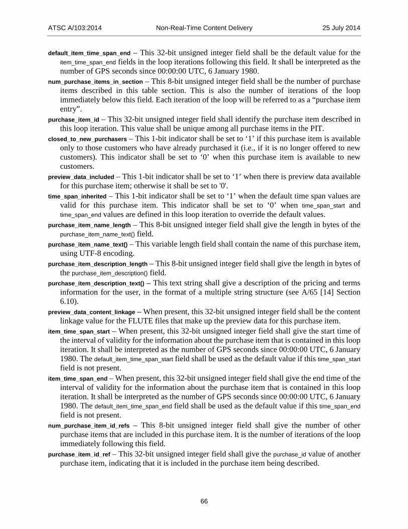
ATSC A/103:2014 Non-Real-Time Content Delivery 25 July 2014
66
default_item_time_span_end – This 32-bit unsigned integer field shall be the default value for the item_time_span_end fields in the loop iterations following this field. It shall be interpreted as the number of GPS seconds since 00:00:00 UTC, 6 January 1980.
num_purchase_items_in_section – This 8-bit unsigned integer field shall be the number of purchase items described in this table section. This is also the number of iterations of the loop immediately below this field. Each iteration of the loop will be referred to as a “purchase item entry”.
purchase_item_id – This 32-bit unsigned integer field shall identify the purchase item described in this loop iteration. This value shall be unique among all purchase items in the PIT.
closed_to_new_purchasers – This 1-bit indicator shall be set to ‘1’ if this purchase item is available only to those customers who have already purchased it (i.e., if it is no longer offered to new customers). This indicator shall be set to ‘0’ when this purchase item is available to new customers.
preview_data_included – This 1-bit indicator shall be set to ‘1’ when there is preview data available for this purchase item; otherwise it shall be set to '0'.
time_span_inherited – This 1-bit indicator shall be set to ‘1’ when the default time span values are valid for this purchase item. This indicator shall be set to ‘0’ when time_span_start and time_span_end values are defined in this loop iteration to override the default values.
purchase_item_name_length – This 8-bit unsigned integer field shall give the length in bytes of the purchase_item_name_text() field.
purchase_item_name_text() – This variable length field shall contain the name of this purchase item, using UTF-8 encoding.
purchase_item_description_length – This 8-bit unsigned integer field shall give the length in bytes of the purchase_item_description() field.
purchase_item_description_text() – This text string shall give a description of the pricing and terms information for the user, in the format of a multiple string structure (see A/65 [14] Section 6.10).
preview_data_content_linkage – When present, this 32-bit unsigned integer field shall be the content linkage value for the FLUTE files that make up the preview data for this purchase item.
item_time_span_start – When present, this 32-bit unsigned integer field shall give the start time of the interval of validity for the information about the purchase item that is contained in this loop iteration. It shall be interpreted as the number of GPS seconds since 00:00:00 UTC, 6 January 1980. The default_item_time_span_start field shall be used as the default value if this time_span_start field is not present.
item_time_span_end – When present, this 32-bit unsigned integer field shall give the end time of the interval of validity for the information about the purchase item that is contained in this loop iteration. It shall be interpreted as the number of GPS seconds since 00:00:00 UTC, 6 January 1980. The default_item_time_span_end field shall be used as the default value if this time_span_end field is not present.
num_purchase_item_id_refs – This 8-bit unsigned integer field shall give the number of other purchase items that are included in this purchase item. It is the number of iterations of the loop immediately following this field.
purchase_item_id_ref – This 32-bit unsigned integer field shall give the purchase_id value of another purchase item, indicating that it is included in the purchase item being described.

ATSC A/103:2014 Non-Real-Time Content Delivery 25 July 2014
67
num_services – This 8-bit unsigned integer field shall give the number of services in the loop immediately following this field.
service_id_ref – This 16-bit unsigned integer field shall give the service_id of an NRT service. The service may be in this broadcast stream, or it may be in a different broadcast stream. If the num_content_items field immediately following this field has value 0, that shall indicate that the service represented by this service_id is included in the purchase item being described. If the num_content_items field immediately following this field has a non-zero value, that shall indicate that the individual content items in the loop following the num_content_items field are included in the purchase item being described.
num_content_items – This 8-bit unsigned integer field shall give the number of content items that are listed in the loop immediately following this field.
content_linkage – This 32-bit unsigned integer value shall match the value of the content_linkage field in the NRT-IT of a content item in the service represented by the service_id_ref field above, indicating that the content item is included in the purchase item being described.
num_purchase_terms – This 8-bit unsigned integer field shall give the number of purchase_terms entries that apply to this purchase item.
purchase_terms_id_ref – This 16-bit unsigned integer field shall match the purchase_terms_id value of an entry in the Purchase Terms and Channels Table in this subnet, indicating that the referenced purchase terms apply to this purchase item.
num_dependency_purchase_refs – This 8-bit unsigned integer field shall give the number of references to other purchase items on which this purchase item is dependent.
dep_purchase_item_id_ref – This 32-bit unsigned integer field shall match the purchase_item_id of another purchase item, with the meaning that one or more of the purchase items so identified must be purchased before the purchase item being described can be purchased.
num_exclusion_purchase_refs – This 8-bit unsigned integer field shall give the number of references to other purchase items which are excluded by this purchase item.
excl_purchase_item_id_ref – This 32-bit unsigned integer field shall match the purchase_item_id of another purchase item, with the meaning that the referenced purchase item should not be offered after the user subscribes to this purchase item.
Note that in the case of a purchase item that contains other purchase items, such as a purchasable bundle containing individually purchasable services and/or content items, or a purchasable service containing individually purchasable content items, this “exclusion” field is not needed to indicate the exclusion relationship, since the receiver can deduce it from the known containment relationship. In such a situation this field can be omitted, to save bandwidth and avoid unnecessary updates to the purchase item.
num_purchase_item_descriptors – This 8-bit unsigned integer field shall give the number of descriptors that appear in the descriptor loop immediately following this field.
purchase_item_descriptor() – This variable length field shall contain a descriptor providing additional information about the purchase item being described.
6.5.2 Purchase Terms and Channels Table There is one Purchase Terms and Channels Table (PTCT) instance for each IP subnet containing NRT services and/or content items which may be purchased or subscribed to. Each PTCT is carried in private sections with table_id value 0xE6, and with syntax and semantics as defined below. The PTCT sections shall be carried in IP multicast datagrams within the Service Signaling Channel for

ATSC A/103:2014 Non-Real-Time Content Delivery 25 July 2014
68
the subnet; i.e., IP multicast datagrams with multicast address 224.0.23.60 and port 4937. Each PTCT instance may contain up to 256 sections.
The following constraints apply to the IP multicast datagrams carrying the PTCT sections. • Each PTCT section shall be in a single datagram. • Different PTCT sections shall be in different datagrams. The syntax of the Purchase Terms and Channels Table shall conform to the syntax shown in
Table 6.9 below. Semantic definitions of the fields in the table appear below the table.
Table 6.9 Syntax of Purchase Terms and Channels Table Syntax No. Bits Format purchase_terms_and_channels_table_section() { table_id 8 0xE6 section_syntax_indicator 1 ‘0’ private_indicator 1 ‘1’ reserved 2 ’11’ section_length 12 uimsbf table_id_extension { protocol_version 8 uimsbf subnet_id 8 uimsbf } reserved 2 ’11’ version_number 5 uimsbf current_next_indicator 1 ‘1’ section_number 8 uimsbf last_section_number 8 uimsbf default_terms_time_span_start 32 uimsbf default_terms_time_span_end 32 uimsbf num_ purchase_terms_in _section 8 uimsbf for (i=0; i< num_purchase_terms_in_section; i++) { purchase_terms_id 32 uimsbf time_span_inherited 1 bslbf reserved 3 ‘111’ purchase_type 4 uimsbf if (time_span_inherited == 0) { terms_time_span_start 32 uimsbf terms_time_span_end 32 uimsbf } purchase_channel_id_ref 8 uimsbf terms_description_length 8 uimsbf terms_description_text() var price_info { monetary_price 14 uimsbf currency_code 10 uimsbf } subscription_period_length 8 uimsbf subscription_period_text() var num_purchase_terms_descriptors 8 uimsbf

ATSC A/103:2014 Non-Real-Time Content Delivery 25 July 2014
69
for (j=0; j<num_purchase_terms_descriptors; j++) { purchase_terms_descriptor() var } } default_chan_time_span_start 32 uimsbf default_chan_time_span_end 32 uimsbf num_purchase_channels_in _section 8 uimsbf for (i=0; i< num_purchase_channels_in_section; i++) { purchase_channel_id 7 uimsbf time_span_inherited 1 bslbf if (time_span_inherited == 0) { chan_time_span_start 32 uimsbf chan_time_span_end 32 uimsbf } contact_url_length 8 uimsbf contact_url_text() var contact_phone_text_length 8 uimsbf contact_phone_text() var num_purchase_channel_descriptors 8 uimsbf for (j=0; j<num_purchase_channel_descriptors; j++) { purchase_channel_descriptor() var } } }
table_id – This 8-bit field shall be set to 0xE6 to identify this table section as belonging to the Purchase Terms and Channels Table.
protocol_version – The purpose of this 8-bit unsigned integer field is to allow, in the future, this Purchase Terms and Channels Table to be structured differently from the definition given here. For the table as defined in this version of this Standard, the value shall be 0x10, where the high order 4 bits indicate the major protocol number and the low order 4 bits indicate the minor protocol number. Non-zero values of protocol_version may be used by future versions of this standard to indicate structurally different tables.
subnet_id – This 8-bit unsigned integer shall indicate the IP subnet associated with this service signaling channel.
version_number – This 5-bit field is the version number of the entire Purchase Terms and Channels Table (PTCT). A PTCT shall be identified by the combination of table_id and table_id_extension. The version_number shall be incremented by 1 modulo 32 when a change in the information carried within the PTCT occurs.
current_next_indicator – This 1-bit indicator shall always be set to ‘1’ for PTCT sections; the PTCT sent is always currently applicable.
section_number – This 8-bit field shall give the section number of this PTCT section, where the PTCT is identified by the combination of table_id and table_id_extension. The section_number of the first section in a PTCT shall be 0x00. The section_number shall be incremented by 1 with each additional section in the PTCT.
last_section_number – This 8-bit field shall give the number of the last section (i.e., the section with the highest section_number) of the PTCT of which this section is a part.

ATSC A/103:2014 Non-Real-Time Content Delivery 25 July 2014
70
default_terms_time_span_start – This 32-bit unsigned integer field shall be the default value for the terms_time_span_start fields in the loop iterations following this field. It shall be interpreted as the number of GPS seconds since 00:00:00 UTC, 6 January 1980.
default_terms_time_span_end – This 32-bit unsigned integer field shall be the default value for the terms_time_span_end fields in the loop iterations following this field. It shall be interpreted as the number of GPS seconds since 00:00:00 UTC, 6 January 1980.
num_purchase_terms_in_section – This 8-bit unsigned integer field shall be the number of purchase terms described in this table section. This is also the number of iterations of the loop immediately below this field. Each iteration of this loop will be referred to as a “purchase terms entry”.
purchase_terms_id – This 32-bit unsigned integer field shall identify the purchase terms described in this loop iteration. This value of purchase_terms_id shall be unique among all the values of purchase_terms_id that appear in the PTCT.
time_span_inherited – This 1-bit indicator shall be set to ‘1’ when the default terms time span values are valid for this purchase item. This indicator shall be set to ‘0’ when terms_time_span_start and terms_time_span_end values are defined in this loop iteration to override the default values.
purchase_type – This 4-bit field shall represent the offered method for purchase of the referenced NRT purchase item. Possible values are: 0: One-time purchase: a one-time, “a-la carte” purchase of the NRT purchase item. The user
will be charged for the amount indicated by monetary_price. 1: Recurring subscription: the nominal subscription period is given by the ‘subscription
period’ string. The subscription will remain In effect until the user explicitly unsubscribes. The subscription_period_text() field indicates the nominal frequency at which the user will be charged for the amount specified by the monetary_price.
2: Free trial subscription: the subscription is intended to provide the user a one-time only, cost-free access to the referenced NRT service.
3 – 15: These values are reserved for future use. terms_time_span_start – When present, this 32-bit unsigned integer field shall give the start time of
the interval of validity for the information about the purchase terms that is contained in this loop iteration. It shall be interpreted as the number of GPS seconds since 00:00:00 UTC, 6 January 1980.
terms_time_span_end – When present, this 32-bit unsigned integer field shall give the end time of the interval of validity for the information about the purchase terms that is contained in this loop iteration. It shall be interpreted as the number of GPS seconds since 00:00:00 UTC, 6 January 1980.
purchase_channel_id_ref – This 8-bit unsigned integer shall identify the particular business entity or system associated with the purchase terms being described. Refer to the associated purchase channel for the URL and contact information for this purchase channel.
purchase_terms_description_length – This 8-bit unsigned integer field shall give the length in bytes of the purchase_terms_description() field.
purchase_terms_description_text() – This text string shall give a description of the pricing and terms information for the user, in the format of a multiple string structure (see A/65 [14] Section 6.10).
monetary_price – This 14-bit field shall be the cost, in currency (see below), of the purchase.

ATSC A/103:2014 Non-Real-Time Content Delivery 25 July 2014
71
currency – This 10-bit field shall encode the currency used to set the cost of the purchase. The currency is specified in 3-digit ISO 4217 [48] currency codes.
subscription_period_length – This 8-bit unsigned integer shall specify the length (in bytes) of the subscription_period_text field.
subscription_period_text() – This text string shall give the subscription period in the form of an XML Schema duration data type. Values such as P1M (one month), P1Y (one year), PT1H (one hour), and fractions thereof are possible.
num_purchase_terms_descriptors – This 8-bit unsigned integer field shall give the number of descriptors in the descriptor loop immediately following this field.
purchase_terms_descriptor() – This variable length field shall contain a descriptor giving additional information about the purchase terms.
default_chan_time_span_start – This 32-bit unsigned integer field shall be the default value for the chan_time_span_start fields in the loop iterations following this field. It shall be interpreted as the number of GPS seconds since 00:00:00 UTC, January 6, 1980.
default_chan_time_span_end – This 32-bit unsigned integer field shall be the default value for the chan_time_span_end fields in the loop iterations following this field. It shall be interpreted as the number of GPS seconds since 00:00:00 UTC, 6 January 1980.
num_purchase_channels_in_section – This 8-bit unsigned integer field shall give the number of purchase channels described in the loop following this field. This is also the number of iterations of the loop immediately below this field. Each iteration of this loop will be referred to as a “purchase channel entry”.
purchase_channel_id – This 8-bit unsigned integer shall identify the particular business entity or system from which NRT purchase items can be acquired. It may also be used by the fixed NRT receiver to restrict purchasing choices to a pre-configured list of channel-choices in the receiver.
chan_time_span_start – When present, this 32-bit unsigned integer field shall give the start time of the interval of validity for the information about the purchase channel that is contained in this loop iteration. It shall be interpreted as the number of GPS seconds since 00:00:00 UTC, 6 January 1980.
chan_time_span_end – When present, this 32-bit unsigned integer field shall give the end time of the interval of validity for the information about the purchase channel that is contained in this loop iteration. It shall be interpreted as the number of GPS seconds since 00:00:00 UTC, 6 January 1980.
channel_url_length – This 8-bit unsigned integer field shall specify the length (in bytes) of the channel_url_text() character string.
channel_url_text() – This text string shall specify the URL used to perform purchase transactions. contact_phone_text_length – This 8-bit unsigned integer field shall specify the length in bytes of the
contact_phone_number() numeric string(s). contact_phone_text() – This numeric string shall specify the one or more telephone numbers the user
may call to perform purchasing with a customer care agent. num_purchase_channel_descriptors – This 8-bit unsigned integer field shall give the number of
descriptors in the descriptor loop immediately following this field. purchase_channel_descriptor() – This variable length field shall contain a descriptor providing
additional information about the purchase channel being described.

ATSC A/103:2014 Non-Real-Time Content Delivery 25 July 2014
72
7. SIGNALING AND ANNOUNCEMENTS FOR MOBILE NRT BROADCASTS The new data structures defined in this major section and its subsections are signaled by the presence of a Protocol Version Descriptor per section 8.1 with the protocol_identifier field set to 0x03, major_protocol_version field set to 0x01 and minor_protocol_version field set to 0x00. This combination associates the major version of data structures defined in A/153:2009 to those herein. This version signaling system is established to enable explicit signaling so that future changes can be made without impacting receivers that support earlier versions.
7.1 Signaling for Mobile NRT Broadcasts 7.1.1 Overview The Signaling subsystem provides the information necessary for a receiver to acquire and present the content of NRT services.
The signaling of ATSC mobile NRT services is based on the system used for signaling M/H services in general, namely the FIC/SMT hierarchy (Fast Information Channel and Service Map Table).
The use of the SMT for signaling ATSC mobile NRT services is nearly identical to its use for signaling ATSC fixed NRT services. However, in the mobile case, a broadcaster has the possibility of expressing some of the service-level information in the Announcement data used for the content guide (see Sections 7.1.4 and 7.2).
The FLUTE extensions used for ATSC mobile NRT services are exactly the same as those used for ATSC fixed NRT services.
This section gives an description of the overall TPC/FIC/SMT signaling hierarchy for M/H services, then specifies (a) how NRT services are signaled in the SMT, and (b) how to map files delivered via the FLUTE multicast file delivery protocol to corresponding Content fragments in the OMA BCAST Service Guide announcements. 7.1.2 Background on ATSC-M/H Signaling ATSC-M/H Signaling has a hierarchical structure in which two distinct steps are necessary for acquisition of the content comprising any M/H service, as specified in A/153 Part 3 [8].
1) M/H Ensemble access: The signaling through the Fast Information Channel (FIC) defined in Section 6.6 of A/153 Part 3 [8] provides the binding information between M/H Service identifiers and M/H Ensembles. It also provides some very high level information about each M/H Service.
2) IP level M/H Service access: The Service Map Table defined in Section 7.3 of A/153 Part 3 [8] provides for each Service: (a) information necessary to access the content of the Service, including IP addresses, UDP ports, and may include other parameters (b) information about media types and parameters necessary to decode and present the content of the Service, and (c) some other descriptive information about the Service.
Figure 7.1 illustrates this signaling hierarchy.

ATSC A/103:2014 Non-Real-Time Content Delivery 25 July 2014
73
Fast Information Channel
FIC-Chunk
M/H Ensemble 0
M/H Service Signaling Channel IP Stream
SMT-MH
M/H Service 0
M/H Ensemble 0 M/H Ensemble 1 M/H Ensemble 0
M/H Service 1
M/H Ensemble M
M/H Service N
M/H Service 0 Table Entry
M/H Service 0IP access info.
M/H Service 1 Table Entry
M/H Service 1IP access info.
M/H Service 0 IP Streams
M/H Service 1 IP Streams
M/H Ensemble 1
M/H Service 0 IP Streams
M/H Ensemble M
M/H Service Signaling Channel IP Stream
SMT-MH
M/H Service N Table Entry
M/H Service NIP access info.
M/H Service N IP Streams
M/H Service Signaling Channel IP Stream
SMT-MH
M/H Service 0 Table Entry
M/H Service 0IP access info.
M/H Service 2 Table Entry
M/H Service 2IP access info.
M/H Service 2 IP Streams
M/H Ensemble 1
M/H Service 2
Figure 7.1 ATSC-M/H Hierarchical Signaling Architecture.
An NRT service is a special case of an M/H service, so NRT services appear in the SMT along with the other services. They are distinguished from other, non-NRT services by the value of the associated service_category field in the SMT.
In the case of an NRT service delivering files via FLUTE sessions, the service information in the SMT includes not only IP addresses and UDP ports, but also Transport Session Identifiers (TSIs) of the FLUTE sessions and optionally bandwidths and FEC parameters for the sessions. 7.1.3 Signaling NRT Services in the Service Map Table Non-Real-Time services in the mobile broadcast emission can be provided as standalone NRT services or as NRT adjunct components for other types of mobile broadcast services. Standalone NRT services carry only file-based content, such as A/V clips, full-length video files, textual/graphics information, and the like. Each standalone mobile NRT service shall be signaled in an SMT-MH section with SMT_MH_protocol_version = 0x00 in the ensemble containing the service. For such standalone NRT services, the service_category field shall be set to 0x0E.
The service_id of a standalone mobile NRT service shall be assigned according to the rules given in Annex B of A/153 Part 3 [8], just as for any other type of mobile service.
NRT adjuncts may be present as components within other types of services (i.e., services with service_category value other than 0x0E), or they may appear as separate NRT services (with service_category value 0x0E) linked to the main service via an Associated Service Descriptor. (defined in Section 8.9 of this Standard.).
In order to avoid ambiguities in the signaling, an M/H service shall not contain NRT components of different major protocol versions. Moreover, an M/H service shall not contain NRT components along with other data services, such as file delivery of external resources to support a
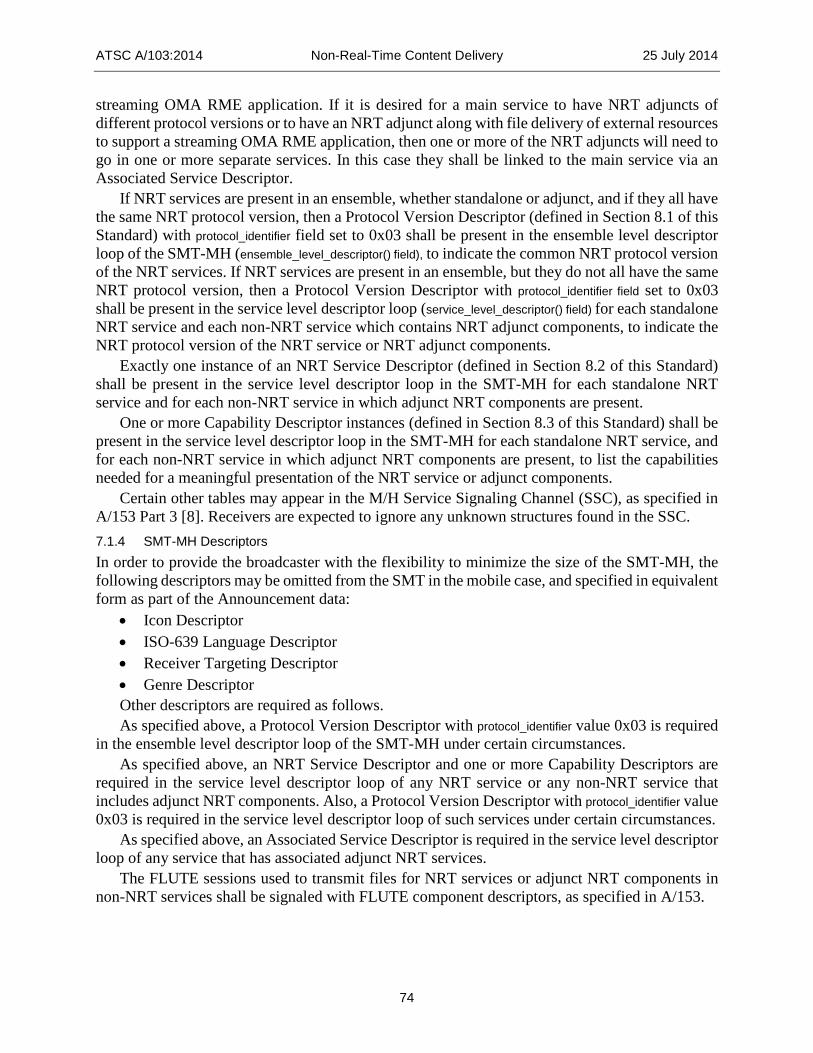
ATSC A/103:2014 Non-Real-Time Content Delivery 25 July 2014
74
streaming OMA RME application. If it is desired for a main service to have NRT adjuncts of different protocol versions or to have an NRT adjunct along with file delivery of external resources to support a streaming OMA RME application, then one or more of the NRT adjuncts will need to go in one or more separate services. In this case they shall be linked to the main service via an Associated Service Descriptor.
If NRT services are present in an ensemble, whether standalone or adjunct, and if they all have the same NRT protocol version, then a Protocol Version Descriptor (defined in Section 8.1 of this Standard) with protocol_identifier field set to 0x03 shall be present in the ensemble level descriptor loop of the SMT-MH (ensemble_level_descriptor() field), to indicate the common NRT protocol version of the NRT services. If NRT services are present in an ensemble, but they do not all have the same NRT protocol version, then a Protocol Version Descriptor with protocol_identifier field set to 0x03 shall be present in the service level descriptor loop (service_level_descriptor() field) for each standalone NRT service and each non-NRT service which contains NRT adjunct components, to indicate the NRT protocol version of the NRT service or NRT adjunct components.
Exactly one instance of an NRT Service Descriptor (defined in Section 8.2 of this Standard) shall be present in the service level descriptor loop in the SMT-MH for each standalone NRT service and for each non-NRT service in which adjunct NRT components are present.
One or more Capability Descriptor instances (defined in Section 8.3 of this Standard) shall be present in the service level descriptor loop in the SMT-MH for each standalone NRT service, and for each non-NRT service in which adjunct NRT components are present, to list the capabilities needed for a meaningful presentation of the NRT service or adjunct components.
Certain other tables may appear in the M/H Service Signaling Channel (SSC), as specified in A/153 Part 3 [8]. Receivers are expected to ignore any unknown structures found in the SSC. 7.1.4 SMT-MH Descriptors In order to provide the broadcaster with the flexibility to minimize the size of the SMT-MH, the following descriptors may be omitted from the SMT in the mobile case, and specified in equivalent form as part of the Announcement data:
• Icon Descriptor • ISO-639 Language Descriptor • Receiver Targeting Descriptor • Genre Descriptor Other descriptors are required as follows. As specified above, a Protocol Version Descriptor with protocol_identifier value 0x03 is required
in the ensemble level descriptor loop of the SMT-MH under certain circumstances. As specified above, an NRT Service Descriptor and one or more Capability Descriptors are
required in the service level descriptor loop of any NRT service or any non-NRT service that includes adjunct NRT components. Also, a Protocol Version Descriptor with protocol_identifier value 0x03 is required in the service level descriptor loop of such services under certain circumstances.
As specified above, an Associated Service Descriptor is required in the service level descriptor loop of any service that has associated adjunct NRT services.
The FLUTE sessions used to transmit files for NRT services or adjunct NRT components in non-NRT services shall be signaled with FLUTE component descriptors, as specified in A/153.

ATSC A/103:2014 Non-Real-Time Content Delivery 25 July 2014
75
An NRT Service that employs the update channel usage described in Section 5.11.1 shall signal this usage with the extension to the FLUTE component descriptor defined in Section 8.6 of this standard.
The other properties of services that are described in descriptors for fixed NRT broadcasts should be described in the OMA BCAST Service Guide data structures for mobile broadcasts.
Other descriptors are not prohibited in the ensemble level, service level or component level descriptor loops. 7.1.5 Mapping FLUTE Files to Content Elements in the Service Guide Descriptions of the individual content items being delivered in a Mobile DTV NRT service are provided through Content fragments of the OMA BCAST Service Guide, as specified in Section 7.2 of this Standard. An NRT content item may be composed of one or more files being delivered via a FLUTE file delivery session. Each file may be a part of one or more content items. It is necessary to identify which files belong to which content items.
These requirements are met by introducing two new elements, FDTContentLinkage and FileContentLinkage, into the XML schema for the FLUTE File Delivery Table (FDT), as defined in Section 5.3 of this Standard. The value of the ContentLinkage element in the Service Guide Content fragment shall match the value of one of these elements for each file that is associated with the content item. The precedence rules for matching the value of the Service Guide ContentLinkage element with the values of the FDTContentLinkage and FileContentLinkage elements are defined in Section 5.3. Each File described in the FLUTE FDT shall have a separate content linkage element for each content item with which it is associated.
For some types of content, it is also necessary to identify which file out of the group of files associated with a content item should be rendered or played back initially. This requirement is met through the ‘entry’ attribute of the FileContentLinkage element in the FLUTE FDT. The use of the entry attribute of FileContentLinkage element is described in Section 5.3.
7.2 Announcement for Mobile NRT Broadcasts 7.2.1 Overview The Announcement subsystem is used to announce information regarding the NRT services and content available on a given ATSC system. The information available through the Announcement subsystem provides receivers with a robust description of the available services and content, as well as the schedule information and access parameters necessary to receive the services and content. 7.2.2 Relationship to Mobile NRT Signaling There is some overlap between the metadata delivered through signaling and via the Announcement subsystem. To the extent possible, metadata items between which there is a semantic mapping should be consistent between the two sources within a transmission, and updates should be synchronized.
However, a receiver might not acquire both metadata sources simultaneously even in a self-consistent transmission. Where metadata regarding NRT services or content delivered via the Announcement subsystem differs from that delivered through signaling, and there exists a defined semantic mapping between the two metadata items, the metadata delivered through signaling shall take precedence.
When any metadata element describing NRT services or content is present in signaling, it shall take precedence over any data present in or absent from the announcement of the corresponding

ATSC A/103:2014 Non-Real-Time Content Delivery 25 July 2014
76
services or content. The process to use for matching of metadata terms for which there is not a defined semantic mapping is undefined. 7.2.3 Approach for Announcing Mobile NRT Services and Content Mobile NRT services and content shall be announced through the ATSC-M/H Announcement subsystem using a service guide, as described in A/153 Part 4 [9], with constraints and extensions for NRT services as specified in this Standard.
Mobile NRT services and content may be described in an instance of the service guide which also describes other services available via ATSC-M/H (e.g., linear audio and video) or they may be described in an entirely separate service guide instance. 7.2.4 ATSC Mobile NRT Service Guide Data Model This Section defines a set of constraints and extensions to the ATSC-M/H Service Guide Data Model defined in Section 6 of A/153 Part 4 [9] for use in announcement of NRT services and content. (The A/153 data model is itself a constrained subset of the data model specified in the OMA BCAST Service Guide specification, Version 1.0 [61].)
Service guide fragments used to announce information regarding NRT services and content shall conform to the data model described in this standard, which extends the A/153 data model (and XML schema) in three distinct ways.
• The allowed values for existing A/153 data model elements are modified or constrained compared to A/153. These changes are intended to be consistent with the OMA BCAST SG XML schema.
• Additional data model elements from the OMA BCAST SG namespace that are not specified in A/153 are employed.
• Additional data model elements not defined in the OMA BCAST SG are introduced. Some are defined within the PrivateExt elements provided for such extensions in the OMA BCAST schema and specified for this purpose in A/153. Others are defined as extensions to non-A/153 OMA elements, at other extensibility points defined within the OMA BCAST SG schema.
A guide that includes mobile NRT services guide is a collection of XML fragments whose syntax is described by A/153 and/or OMA BCAST SG (using the OMA BCAST XML namespace), together with additional XML elements defined by this standard (using the ATSC NRT namespace defined in Section 3.6).
Note: The following conventions apply to all tables in this Section: • Metadata items which are represented as XML elements are shown in plain text. • Metadata items which are represented as XML attributes are shown in italics. • Extensions/constraints to the allowed values of A/153 data model elements are shown with
a border. • Additions to the data model specified in A/153 that make use of existing OMA BCAST
data model elements are highlighted in light gray. • Additions to the data model specified in OMA BCAST (and therefore making use of the
ATSC NRT namespace) are highlighted in light gray and bold. The XML schema definitions for the new elements described in the tables in this section (those
elements highlighted in light gray and bold in Table 7.1 and Table 7.8) can be found in the XML schema file identified in section 3.6 of this document. When any of these elements appear in the

ATSC A/103:2014 Non-Real-Time Content Delivery 25 July 2014
77
service guide, their syntax shall conform to these XML schema definitions. When any of these elements appear in the service guide, their semantics shall be as defined in this section. 7.2.4.1 Service Fragment Use of the Service fragment of the service guide shall conform to the specifications in Section 6.1 of A/153 Part 4 [9] with extensions for NRT services as shown in Table 7.1.
Table 7.1 Service Fragment Service id version validFrom validTo globalServiceID weight baseCID
ServiceType
Name Description AudioLanguage languageSDPTag TextLanguage languageSDPTag ParentalRating ratingSystem ratingValueName TargetUserProfile Genre Extension url Description PreviewDataReference idRef usage BroadcastArea PrivateExt ServicePrivateExt ConsumptionModel EssentialCapabilities CapabilityCodes CapabilityString category CapabiltyOrGroup CapabilityCodes CapabilityString category NonessentialCapabilities CapabilityCodes

ATSC A/103:2014 Non-Real-Time Content Delivery 25 July 2014
78
CapabilityString category CapabilityOrGroup CapabilityCodes CapabilityString category RequiredStorage AutoUpdate ContentDefaults RequiredStorage UpdatesAvailable AcquisitionTime InternetLocations all AssociatedServiceReference idRef
The following adaptations and extensions apply in addition to those described in Section 6.1 of A/153 Part 4 [9]. 7.2.4.1.1 Service Type The ServiceType element values are extended to include a proprietary ATSC NRT type:
• A ServiceType element shall be included with value 129 to indicate that the Service fragment contains information regarding an ATSC NRT service.
• In the case of an adjunct NRT service, this element shall be included in addition to the ServiceType element specifying the main service type(s).
7.2.4.1.2 Receiver Targeting A specific usage of the OMA BCAST SG TargetUserProfile element is employed to optionally associate a service with a particular user profile. The detailed syntax and semantics of this element are described in Section 9.3.
A specific usage of the OMA BCAST SG BroadcastArea element is employed to optionally associate a service with a particular geographic location. The detailed syntax and semantics of this element are described in Section 9.3. 7.2.4.1.3 SMT-Related Private Extensions Elements from the ATSC NRT namespace may be used within the OMA PrivateExt element, to indicate SMT-related attributes, as listed in Table 7.2. As these parameters are required to be indicated in the NRT Service Descriptor and the Capabilities Descriptor in the SMT, it is redundant and hence optional to transmit them.

ATSC A/103:2014 Non-Real-Time Content Delivery 25 July 2014
79
Table 7.2 SMT-Related Private Extensions
Name Type Category Card-inality Description Data Type
ConsumptionModel E2 NO/TO 0..1 NRT consumption mode. Value from Table 8.6. Required.
unsignedByte
AutoUpdate E2 NO/TO 0..1 Whether to offer the user the option to auto-update content items. boolean
RequiredStorage E2 NO/TO 0..1 Total storage a receiver is expected to allocate to present the service, in kilobytes. unsignedInt
Essential Capabilities E2 NO/TO 0..1
Capabilities essential for a meaningful presentation of the service. Contains the following elements:
CapabilityCodes CapabilityString CapabilityOrGroup
CapabilityCodes E3 NO/TO 0..1 A list of code points from Table A.1 in numeric form. See capability_code (Section 8.3).
list of unsignedByte
CapabilityString E3 NO/TO 1..N
A string containing the representation of a capability per Table 8.8 and the text following it. See capability_string (Section 8.3). Contains the following attribute:
category
string
category A NO/TO 1..1 Gives the capability category of the capability represented by this CapabilityString element. unsignedByte
CapabilityOrGroup E3 NO/TO 0..N
Group of capability codes and/or strings that are combined by “OR” logic to represent a single capability (i.e., a receiver satisfies the capability represented by the CapabilityOrGroup if it satisfies at least one of the capabilities in the group.)
CapabilityCodes E4 NO/TO 0..1 A list of capability code points from Table A.1 in numeric form. See capability_code (Section 8.3).
list of unsignedByte
CapabilityString E4 NO/TO 1..N
A string containing the representation of a capability per Table 8.8 and the text following it. See capability_string (Section 8.3). Contains the following attribute:
category
string
category A NO/TO 1..1 Gives the capability category of the capability represented by this CapabilityString element. unsignedByte
NonEssential Capabilities E2 NO/TO 0..1
Capabilities relevant to presenting the service, but not essential for a meaningful presentation. Contains the following elements:
CapabilityCodes CapabilityString CapabilityOrGroup
CapabilityCodes E3 NO/TO 0..1 A list of code points from Table A.1 in numeric form. See capability_code (Section 8.3).
list of unsignedByte
CapabilityString E3 NO/TO 1..N
A string containing the representation of a capability per Table 8.8 and the text following it. See capability_string (Section 8.3).
string

ATSC A/103:2014 Non-Real-Time Content Delivery 25 July 2014
80
Contains the following attribute: category
category A NO/TO 1..1 Gives the capability category of the capability represented by this CapabilityString element. unsignedByte
CapabilityOrGroup E3 NO/TO 0..N
Group of capability codes and/or strings that are combined by “OR” logic to represent a single capability (i.e., a receiver satisfies the capability represented by the CapabilityOrGroup if it satisfies at least one of the capabilities in the group.)
CapabilityCodes E4 NO/TO 0..1 A list of capability code points from Table A.1 in numeric form. See capability_code (Section 8.3).
list of unsignedByte
CapabilityString E4 NO/TO 1..N
A string containing the representation of a capability per Table 8.8 and the text following it. See capability_string (Section 8.3). Contains the following attribute:
category
string
category A NO/TO 1..1 Gives the capability category of the capability represented by this CapabilityString element. unsignedByte
The optional ConsumptionModel element provides the mode in which the broadcaster expects the receiver to process the transmitted content within the NRT service. This element is the analogue of the SMT NRT Service Descriptor consumption_model field (Section 8.2).
The optional AutoUpdate element indicates whether the option to auto-update the content within the service (in the fashion of an RSS feed) should be offered to the user. This element is the analogue of SMT NRT Service Descriptor auto-update (Section 8.2).
The optional RequiredStorage element provides an estimate of the storage required for all the files that make up a content item, including any future updates. This element is the analogue of SMT NRT Service Descriptor storage_reservation (Section 8.2).
The optional Capabilities element provides the same information as the SMT Capabilities Descriptor in the fixed case, and it is subject to the same constraints with respect to values and usage at content item level as described in Section 8.3. 7.2.4.1.4 ContentDefaults An ATSC NRT namespace extension may be used to provide, for convenience and compactness reasons, default values for certain of the content-level elements defined in Sections 7.2.4.2 and 7.2.4.3. For the details of the data model and of the overriding semantics, see the descriptions in the appropriate sections.

ATSC A/103:2014 Non-Real-Time Content Delivery 25 July 2014
81
Table 7.3 Content Defaults
Name Type Category Card-inality Description Data Type
ContentDefaults E2 NO/TM 0..1
Default values for the corresponding content-level elements, which will supersede these values if present. Contains the following elements:
RequiredStorage UpdatesAvailable AcquisitionTime InternetLocations
RequiredStorage E3 NO/TM 0..1 Default value for Content RequiredStorage value (in kilobytes) unsignedInt
UpdatesAvailable E3 NO/TM 0..1 Default value for Content UpdatesAvailable value boolean
AcquisitionTime E3 NO/TM 0..1 Default value for Schedule DistributionWindow duration value (in seconds)
unsignedInt
InternetLocations E3 NO/TO 0..1
Default value for Content InternetLocations value. Contains the following attribute:
all
list of anyUri
all A NO/TM 0..1 Indication whether all files are available on the internet. Default: false
boolean
7.2.4.1.5 Associated Services An AssociatedServiceReference element from the ATSC NRT namespace may be used within the OMA PrivateExt element to indicate that an M/H service has an adjunct NRT service.
Table 7.4 Associated Services
Name Type Category Card-inality Description Data
Type
AssociatedServiceReference E2 NO/TM 0..N
Reference to the Service fragment of an adjunct NRT service. Contains the following attribute:
idRef
idRef A NO/TM 1 Identification (id attribute) of the associated NRT Service fragment. anyUri
There may be multiple instances of this element for a given M/H service if an M/H service has several adjunct NRT services. An NRT service may also be an adjunct to multiple M/H services, in which case there will be multiple AssociatedServiceReference elements that point to the same Service fragment of NRT type. 7.2.4.2 Schedule Fragment Use of the Schedule fragment of the service guide shall conform to the specifications in Section 6.2 of A/153 Part 4 [9], with extensions for NRT services using existing OMA BCAST elements as shown in Table 7.5.

ATSC A/103:2014 Non-Real-Time Content Delivery 25 July 2014
82
Table 7.5 Schedule Fragment Schedule id version defaultSchedule onDemand validFrom validTo ServiceReference idRef ContentReference idRef contentLocation DistributionWindow startTime endTime duration PresentationWindow startTime endTime duration PrivateExt
The following adaptations and extensions apply in addition to those described in Section 6.3 of A/153 Part 4 [9]. 7.2.4.2.1 Distribution Window The definition of DistributionWindow elements in a Schedule fragment associated with an ATSC NRT service shall be as specified in Table 7.6. Note that these entries and associated meaning are similar, but not identical, to the Cachecast services as specified in the OMA BCAST Service Guide [61], Section 5.1.2.2.

ATSC A/103:2014 Non-Real-Time Content Delivery 25 July 2014
83
Table 7.6 Distribution Window
Name Type Category Card-inality Description Data Type
DistributionWindow E2 NM/ TM 0..N
Time interval in which the referenced content specified by ContentID is available for delivery. Contains the following attributes:
startTime endTime duration
startTime A NO/ TM 0..1
Start of DistributionWindow. If not given, the validity is assumed to have begun at some time in the past. This field contains the 32bits integer part of an NTP time stamp.
unsignedInt
endTime A NO/ TM 0..1
End of DistributionWindow. If not given, the validity is assumed to end in undefined time in the future. This field contains the 32bits integer part of an NTP time stamp.
unsignedInt
duration A NO/ TM 0..1
The maximum amount of time that a terminal that begins to acquire the Content item during this DistributionWindow should allow to complete the acquisition. The unit of time is in seconds.
unsignedInt
Note: A set of DistributionWindow elements corresponds to some of the information provided in the fixed NRT case by the NRT-IT and its descriptors.
• The startTime and endTime of one or more DistributionWindow elements is equivalent to the Time Slot Descriptor, except that any repetition is explicitly expressed. Note that the definition above is consistent with the OMA BCAST SG, in that it assumes that the transmission continues sufficiently far past endTime to ensure that a receiver that begins to listen at endTime should be able to acquire the content item.
• The duration of a DistributionWindow element is equivalent to the acquisition_time field in the NRT-IT. If this attribute is not present, but an AcquisitionTime element is present as part of a ContentDefaults element in the Service fragment, the value of that element is used. Otherwise the expected acquisition time is undefined.
7.2.4.2.2 Presentation Window As constrained in A/153 Part 4 [9], and not altered herein, at most one instance of PresentationWindow element is allowed to be instantiated per ContentReference element instance. The duration attribute defined in the OMA BCAST Service Guide [61] Section 5.1.2.2 may also be used. The definition of PresentationWindow elements in a Schedule fragment associated with an ATSC NRT service shall be as specified in Table 7.7. Note that these entries and the associated meaning are similar, but not identical, to that of Cachecast services as specified in the OMA BCAST SG [61] Section 5.1.2.2.

ATSC A/103:2014 Non-Real-Time Content Delivery 25 July 2014
84
Table 7.7 Presentation Window
Name Type Category Card-inality Description Data Type
PresentationWindow E2 NM/ TM 0..1
Time interval in which the referenced content specified by ContentID is available for rendering. Contains the following attributes:
startTime endTime duration
startTime A NM/ TM 0..1
Start of PresentationWindow. If not given the validity is assumed to have begun at some time in the past. The earliest instant at which rendering of the associated content item can begin. This field contains the 32bits integer part of an NTP time stamp.
unsignedInt
endTime A NM/ TM 0..1
End of PresentationWindow. If not given, the validity is assumed to end in undefined time in the future. The latest instant at which the rendering of the associated content item can begin. This field contains the 32bits integer part of an NTP time stamp.
unsignedInt
duration A NO/TO 0..1 Time duration of the referenced content for rendering, in seconds. unsignedInt
Note: A PresentationWindow element corresponds to some of the information provided in the fixed NRT case by the NRT-IT and its descriptors.
• The endTime attribute of the PresentationWindow element is equivalent to the expiration field in the NRT-IT.
• The duration attribute of the PresentationWindow element is equivalent to the playback_length_in_seconds field in the NRT-IT.
7.2.4.3 Content Fragment Use of the Content fragment of the service guide shall conform to the specifications in Section 6.3 of A/153 Part 4 [9] with extensions for NRT services as shown in Table 7.8. In the case of an ATSC NRT service, a Content fragment corresponds to a content item that is potentially composed of multiple transported files. The semantics of the service guide closely match the OMA BCAST Cachecast service case, with the appropriate generalization to a file collection.
Table 7.8 Content Fragment (next page)

ATSC A/103:2014 Non-Real-Time Content Delivery 25 July 2014
85
Content id version validFrom validTo globalContentID baseCID ServiceReference idRef weight Name Description StartTime EndTime AudioLanguage languageSDPTag TextLanguage languageSDPTag Length ParentalRating ratingSystem ratingValueName TargetUserProfile Genre Extension url Description PreviewDataReference idRef usage BroadcastArea PrivateExt ContentPrivateExt masterItem ContentLinkage EssentialCapabilities CapabilityCodes CapabilityString category CapabilityOrGroup CapabilityCodes CapabilityString category NonessentialCapabilities CapabilityCodes CapabilityString category CapabilityOrGroup

ATSC A/103:2014 Non-Real-Time Content Delivery 25 July 2014
86
CapabilityCodes CapabilityString category RequiredStorage UpdatesAvailable InternetLocations all PlaybackDelay
The following adaptations and extensions apply in addition to those described in Section 6.1 of A/153 Part 4 [9]. 7.2.4.3.1 Receiver Targeting A specific usage of the OMA BCAST SG TargetUserProfile element is employed to optionally associate a content item with a particular user profile. The detailed syntax and semantics of this element are described in Section 9.3.
A specific usage of the OMA BCAST SG BroadcastArea element is employed to optionally associate a content item with a particular geographic location. The detailed syntax and semantics of this element are described in Section 9.3. 7.2.4.3.2 Content-Level Private Extensions Elements from the ATSC NRT namespace are used within the OMA PrivateExt element, to indicate content-level attributes, as listed below.

ATSC A/103:2014 Non-Real-Time Content Delivery 25 July 2014
87
Table 7.9 Content-Level Private Extensions Name Type Category Cardinality Description Data Type
masterItem A NM/TM 0..1
This boolean flag shall indicate, when set to”true”, that the content item is the “master” content item. A “master” content item is the content item to be launched when the service is selected. Setting this flag to “false” shall indicate the content item is not a “master” content item. Only one content item in a given service shall be indicated as a “master” content item.
boolean
ContentLinkage E2 NM/TM 1 ID of this content item, used to map files to content items. unsignedInt
Essential Capabilities E2 NO/TO 0..1
Capabilities essential for a meaningful presentation of the content item. Contains the following elements:
CapabilityCodes CapabilityString CapabilityOrGroup
CapabilityCodes E3 NO/TO 0..1 A list of code points from Table A.1 in numeric form. See capability_code (Section 8.3).
list of unsignedByte
CapabilityString E3 NO/TO 1..N
A string containing the representation of a capability per Table 8.8 and the text following it. See capability_string (Section 8.3). Contains the following attribute:
category
string
category A NO/TO 1..1 Gives the capability category of the capability represented by this CapabilityString element.
unsignedByte
CapabilityOrGroup E3 NO/TO 0..N
Group of capability codes and/or strings that are combined by “OR” logic to represent a single capability (i.e., a receiver satisfies the capability represented by the CapabilityOrGroup if it satisfies at least one of the capabilities in the group.)
CapabilityCodes E4 NO/TO 0..1 A list of capability code points from Table A.1 in numeric form. See capability_code (Section 8.3).
list of unsignedByte
CapabilityString E4 NO/TO 1..N
A string containing the representation of a capability per Table 8.8 and the text following it. See capability_string (Section 8.3). Contains the following attribute:
category
string
category A NO/TO 1..1 Gives the capability category of the capability represented by this CapabilityString element.
unsignedByte
Nonessential Capabilities E2 NO/TO 1..N
Capabilities relevant to presenting the content item, but not essential for a meaningful presentation. Contains the following elements:
CapabilityCodes CapabilityString CapabilityOrGroup

ATSC A/103:2014 Non-Real-Time Content Delivery 25 July 2014
88
CapabilityCodes E3 NO/TO 0..1 A list of capability code points from Table A.1, in numericform. See capability_code (Section 8.3).
list of unsignedByte
CapabilityString E3 NO/TO 1..N
A string containing the representation of a capability per Table 8.8 and the text following it. See capability_string (Section 8.3). Contains the following attribute:
category
string
category A NO/TO 1..1 Gives the capability category of the capability represented by this CapabilityString element.
unsignedByte
CapabilityOrGroup E3 NO/TO 0..N
Group of capability codes and/or strings that are combined by “OR” logic to represent a single capability (i.e., a receiver satisfies the capability represented by the CapabilityOrGroup if it satisfies at least one of the capabilities in the group.)
CapabilityCodes E4 NO/TO 0..1 A list of capability code points from Table A.1, in decimal form. See capability_code (Section 8.3).
list of unsignedByte
CapabilityString E4 NO/TO 1..N
A string containing the representation of a capability as specified in Table 8.8 and the text following it. See capability_string (Section 8.3). Contains the following attribute:
category
string
category A NO/TO 1..1 Gives the capability category of the capability represented by the CapabilityString element.
unsignedByte
RequiredStorage E2 NM/TM 0..1 Storage required for the content item, in kilobytes. unsignedInt
UpdatesAvailable E2 NM/TM 0..1 Flag to indicate whether updates will be provided for this content item. boolean
InternetLocations E2 NO/TO 0..1
Content-locations of files within this content item that are available over the internet. Contains the following attribute:
All
list of anyUri
all A NO/TM 0..1 Indication whether all files in the content item are available on the internet. Default: false
boolean
PlaybackDelay E2 NO/TO 0..1 Playback delay in seconds for a progressive download content item. Maximum value is 1048575
unsignedInt
The ContentLinkage element shall be instantiated for each Content fragment in the Service Guide. Its value links the content description published through the service guide with the associated file or files carried on the FLUTE file delivery session for the NRT service. Each file associated with the content item represented by the Content fragment shall have a FLUTE FDT content linkage tag matching the value of the ContentLinkage element (where “content linkage tag” is defined in Section 5.3.) The value of the ContentLinkage element shall be set to an unsigned integer which is unique within the associated NRT service for the period of time beginning when the content item is first advertised through the service guide or any of its files

ATSC A/103:2014 Non-Real-Time Content Delivery 25 July 2014
89
appear in FLUTE FDT instances, and ending when the content item no longer appears in the guide and none of its files appear in FLUTE FDT instances (taking into account the Expires attribute of the FLUTE FDT instances). This element is the analogue of NRT-IT content_linkage (Section 6.3) for the fixed case.
The Capabilities element provides the same information as the Capabilities Descriptor in the fixed case, and it is subject to the same constraints with respect to values and usage at service and content item level as described in Section 8.3.
The optional RequiredStorage element provides an estimate of the storage required for all the files that make up a content item, including any future updates. This element is the analogue of NRT-IT content_size (Section 6.3) for the fixed case. If this element is absent at the content level but is provided in a ContentDefaults element at the service level, that value shall apply. If absent at both levels, the required storage is undefined.
The optional UpdatesAvailable element specifies whether the content item will be updated periodically. If so, receiving devices are expected to monitor for changes the TOI associated with each file associated with the content item’s content linkage value. If not, updates are not expected to be provided for the associated content item(s), and receivers are not expected to look for them. This element is the analogue of NRT-IT updates_available (Section 6.3) for the fixed case. If this element is absent but is provided in a ContentDefaults element at the service level, that value shall apply. If absent at both levels, the default value is false.
The optional InternetLocations element provides a list of URLs corresponding to files that are part of the content item and are available via the internet as well as via the broadcast Each URL shall be the Content-Location of a file described in the FDT for the FLUTE session delivering the content item. See the discussion in Section 5.9. If the attribute all has the value “true” (default: false), the element indicates that all files in a content item are available via the internet using the Content-Location from the FDT, and the element shall be empty. This element is the analogue of the Internet Location Descriptor and the available_on_internet indicator used in the NRT-IT (Section 8.8) for the fixed case. If this element is absent but is provided in a ContentDefaults element at the service level, that value shall apply (the only practically useful value in this case is with all=“true”). An element with all=“false” (or the attribute omitted) may be used to override for a specific content item a service level default that all files are available. If absent at both levels, no files are indicated as available via the Internet.
The optional PlaybackDelay element provides the number of seconds following reception of the first byte of any file in the associated content the receiver shall wait before rendering may start, while buffering the incoming FLUTE stream(s). A value of zero shall indicate playback may commence immediately. When the PlaybackDelay element is absent, the receiver is expected to retrieve the complete content item prior to rendering. This element is the analogue of NRT-IT playback_delay (Section 6.3) for the fixed case. 7.2.4.4 Access Fragment Use of the Access fragment of the service guide shall conform to the specifications in Section 6.4 of A/153 Part 4 [9], with the addition of the option to instantiate the PreviewDataReference element as defined by OMA BCAST SG [61] for the Access fragment. 7.2.4.5 Session Description Fragment Use of the Session Description fragment of the service guide shall conform to the specifications in Section 6.5 of A/153 Part 4 [9].

ATSC A/103:2014 Non-Real-Time Content Delivery 25 July 2014
90
7.2.4.6 Purchase Metadata for M/H The data structures in this section provide the basic metadata describing purchase items and the terms for purchase of such items, as well as descriptions of the “channels” (phone numbers and web site URLs) through which purchases can be made manually. A full system definition incorporating the ability to purchase services and content involves a number of aspects that are out of scope for the present standard. Such aspects include (but are not limited to) specification of the receiver components that acquire and manage security keys necessary to decrypt the content, and LTKM and STKM delivery. A/153 Part 6 [66] provides specifications for such aspects. 7.2.4.6.1 Purchase Item Fragment Use of the Purchase Item fragment of the service guide shall conform to the specifications in Section 6.6 of A/153 Part 4 [9], with the following changes:
1) E1 element PurchaseItemReference is added, exactly as it is specified in the OMA BCAST v1.0 Service Guide [61] Section 5.1.2.6.
2) E1 element DependencyReference is added, exactly as it is specified in the OMA BCAST v1.0 Service Guide [61] Section 5.1.2.6.
3) E1 element ExclusionReference is added, exactly as it is specified in the OMA BCAST v1.0 Service Guide [61] Section5.1.2.6.
4) Top-level attribute closed is added, exactly as it is specified in the OMA BCAST v1.0 Service Guide [61] Section 5.1.2.6.
The revised data structure of the Purchase Item fragment is shown in Table 7.10 (added parameters are highlighted).

ATSC A/103:2014 Non-Real-Time Content Delivery 25 July 2014
91
Table 7.10 PurchaseItem Fragment PurchaseItem id version validFrom validTo globalPurchaseItemID binaryPurchaseItemID weight closed ServiceReference idRef ScheduleReference idRef PurchaseItemReference idRef Name Description StartTime EndTime ParentalRating ratingSystem ratingValueName DependencyReference idRef ExclusionReference idRef Extension url Description PrivateExt
7.2.4.6.2 Purchase Data Fragment Use of the Purchase Data fragment of the service guide shall conform to the specifications in Section 6.7 of A/153 Part 4 [9], with the following change:
• E1 element TermsOfUse is added, exactly as it is specified in the OMA BCAST v1.0 Service Guide [61] Section 5.1.2.7.
To control the subscription/purchasing of certain NRT purchase items, it may be useful or even necessary from service provider policy and/or legal reasons to provide a “terms of use” advisory to the end user, as a precondition to fulfillment of the associated purchase transaction. For those purchase items, the related E1 element TermsOfUse in the PurchaseData fragment of the OMA BCAST v1.0 Service Guide [61] should be included in the PurchaseData fragment. When TermsofUse is present with its “type” attribute set to ‘0’, then it is recommended that the TermsOfUse/TermsOfUseText or TermOfUse/PreviewDataIDRef, as defined in the OMA BCAST v1.0 Service Guide [61], be provided to the end-user, along with other descriptive information about the purchase items carried in other elements of the Service Guide.

ATSC A/103:2014 Non-Real-Time Content Delivery 25 July 2014
92
The revised data structure of the Purchase Data fragment is shown in Table 7.11 (added parameter is highlighted).
Table 7.11 PurchaseData Fragment PurchaseData id version validFrom validTo Description PriceInfo subscriptionType MonetaryPrice currency SubscriptionPeriod PurchaseItemReference idRef PurchaseChannelReference idRef PreviewDataReference idRef usage TermsOfUse type id userConsentRequired Country Language PreviewDataIDRef TermsOfUseText PrivateExt
7.2.4.6.3 Purchase Channel Fragment Use of the Purchase Channel fragment of the service guide shall conform to the specifications in Section 6.8 of A/153 Part 4 [9]. 7.2.4.6.4 Preview Data Fragment Use of the Preview Data fragment of the service guide shall conform to the specifications in Section 6.9 of A/153 Part 4 [9].
In particular, this fragment and the associated delivery machinery defined in the OMA BCAST Service Guide specification [61] is used to provide icons for services and content items, via PreviewDataReference elements in the Service and Content fragments (with usage=“2”). This means that the Icon Descriptor defined for the fixed SMT is not expected to be used for mobile NRT services.
8. BASIC DESCRIPTORS This section provides definitions and other information about the descriptors which are referenced in this document, except for the Receiver Targeting Descriptor, which is defined in Section 9.2.

ATSC A/103:2014 Non-Real-Time Content Delivery 25 July 2014
93
8.1 Protocol Version Descriptor (PVD) The Protocol Version Descriptor is used to identify the major version numbers of data structures or services in the ATSC Standards. If the PVD of a data structure or service indicates a major version number higher than that which a given receiver supports, that receiver is expected to disregard the associated data structure or service. If the PVD indicates a minor version number higher than that which a given receiver supports, that receiver is expected to attempt to present the service as usual. Certain bits in fields identified as containing “reserved” values in previous versions of the standard may be defined in later versions and associated with certain minor_version_number values.
The bit stream syntax of the Protocol Version Descriptor shall be as shown in Table 8.1.
Table 8.1 Bit Stream Syntax for the Protocol Version Descriptor Syntax No. of Bits Format protocol_version_descriptor() { descriptor_tag 8 0xC3 descriptor_length 8 uimsbf protocol_identifier 8 uimsbf major_protocol_version 4 uimsbf minor_protocol_version 4 uimsbf for (i=0; i<N; i++) { reserved 8 bslbf } }
descriptor_tag – This 8-bit unsigned integer shall have the value 0xC3, identifying this descriptor as a protocol_version_descriptor().
descriptor_length – This 8-bit unsigned integer shall specify the length (in bytes) immediately following this field up to the end of this descriptor.
protocol_identifier – This 8-bit unsigned integer shall be used to indicate the protocol whose version is being identified in the major/minor protocol version fields to follow. The value of the protocol_identifier field shall be as defined in Table 8.2.
Table 8.2 Protocol Identifier protocol_identifier Meaning 0x00 Forbidden 0x01 Legacy A/90 data services, conforming to ATSC A/90 [2] 0x02 IP Subnet defined in Section 5.1.1 0x03 Non-Real-Time services 0x04 – 0x7F Reserved for future use by ATSC 0x80 – 0xFF Reserved for experimental use
major_protocol_version – This 4-bit unsigned integer shall specify the major portion of the protocol version. A change in the major_protocol_version shall indicate a non-backward compatible level of change.

ATSC A/103:2014 Non-Real-Time Content Delivery 25 July 2014
94
minor_protocol_version – This 4-bit unsigned integer shall specify the minor portion of the protocol version. A change in the minor_protocol_version, provided the major_protocol_version remains the same, shall indicate a backward-compatible level of change. When a Protocol Version Descriptor with protocol_identifier value 0x01 is present in the
program_info descriptor loop of a PMT section, it shall indicate that the collection of all program elements of stream types 0x06, 0x0B, 0x0D, 0x14, 0x95 and 0xC2 in the associated MPEG-2 program constitute a data service that conforms to the ATSC A/90 Standard [2]. When a Protocol Version Descriptor with protocol_identifier value 0x01 is present in the descriptor loop following ES_info_length of a subset of the program elements of a PMT section, it shall indicate that the program elements in that subset constitute a data service that conforms to the ATSC A/90 Standard [2]. In these situations the major_protocol_version value of 0x1 and minor_protocol_version value of 0x0 shall indicate that set of program elements conform to the July 2000 A/90 release with the April/May 2002 Amendment 1 and Corrigenda 1 and 2 [2].
When a Protocol Version Descriptor with protocol_identifier value 0x02 is present in the program_info descriptor loop of a PMT section, it shall indicate that the collection of all program elements of stream_type 0x0D in the associated MPEG-2 program constitute an IP subnet that conforms to the specifications in Section 5.1.1 of this standard. When a Protocol Version Descriptor with protocol_identifier value 0x02 is present in the descriptor loop following ES_info_length of a subset of the program elements of a PMT section, it shall indicate that the program elements in that subset constitute an IP subnet that conforms to the specifications in Section 5.1.1 of this standard. In these situations the values of major_protocol_version and minor_protocol_version shall be as defined in Table 8.3.
Table 8.3 Protocol Version for protocol_identifier = 0x02 (IP Subnet) major_protocol_version minor_protocol_version Meaning 0x0 (don’t care) Forbidden
0x1 0x0
IP subnet and Service Signaling Channel (SSC as specified in Section 5.1.1 of the present standard, with the first byte of each table in the SSC giving the table_id of the table, and the fourth byte giving the protocol_version of the table.
0x1 0x1 – 0xF Reserved for future use by ATSC 0x2 – 0xF all Reserved for future use by ATSC
When the protocol_identifier field has value 0x03 (indicating NRT service) the values of major_protocol_version and minor_protocol_version shall be as defined in Table 8.4.
Table 8.4 Protocol Version for protocol_identifier = 0x03 (NRT) major_protocol_version minor_protocol_version Meaning 0x0 (don’t care) Forbidden
0x1 0x0 NRT services as specified in the present NRT standard, not including those data structures and semantics of NRT services for which version signaling is defined within the NRT standard.
0x1 0x1 – 0xF Reserved for future use by ATSC 0x2 – 0xF all Reserved for future use by ATSC

ATSC A/103:2014 Non-Real-Time Content Delivery 25 July 2014
95
If a protocol version is signaled by a Protocol Version Descriptor, and if different structures conforming to different versions of that protocol are present, then multiple instances of the Protocol Version Descriptor with the same protocol_identifier value may appear.
8.2 NRT Service Descriptor The NRT Service Descriptor indicates the presence of NRT components within a service, indicates the usage/consumption model for a non-real-time service, and gives other optional information about the service.
A variety of user experiences are possible for NRT services. An informative description of the usage/consumption models defined in this release of the standard may be found in Annex B.
Whenever a service contains NRT components, one instance of an NRT Service Descriptor shall be included in the SMT in the descriptor loop indicated by the term service_level_descriptor().
The bit stream syntax for the NRT Service Descriptor shall be as shown in Table 8.5.
Table 8.5 Bit Stream Syntax for the NRT Service Descriptor Syntax No. of Bits Format NRT_service_descriptor() { descriptor_tag 8 0xC4 descriptor_length 8 uimsbf reserved 2 ‘11’ consumption_model 6 uimsbf auto-update 1 bslbf storage_reservation_present 1 bslbf default_content_size_present 1 bslbf reserved 5 ‘11111’ if (storage_reservation_present==1) { storage_reservation 24 uimsbf if (default_content_size_present==1) { default_content_size 40 uimsbf } for (j=0; j< N; j++) { reserved 8 bslbf } }
descriptor_tag – This 8-bit unsigned integer shall have the value 0xC4, identifying this descriptor as an NRT_service_descriptor().
descriptor_length – This 8-bit unsigned integer shall specify the length (in bytes) immediately following this field up to the end of this descriptor.
consumption_model – This 6-bit unsigned integer shall signal the intended consumption model for the NRT service associated with the descriptor. The codes for NRT consumption Models shall be as defined in Table 8.6. Annex B of this Standard provides a description of the NRT Consumption Models listed here. Note: other Consumption Models for NRT services might be defined in future ATSC standards.

ATSC A/103:2014 Non-Real-Time Content Delivery 25 July 2014
96
Table 8.6 NRT Consumption Models consumption_model Meaning 0x00 Forbidden.
0x01 Browse & Download – The NRT service offers content that can be selected for later download.
0x02 Portal – The NRT service provides an experience similar to a web browser access. Files needed to support text/graphics rendering are available in the associated FLUTE session.
0x03
Push – The NRT service offers request-based content. Receivers are expected to offer the user a choice whether or not to automatically update content associated with the service. For such services, if the user selects the auto-update option, the receiver caches service-related content and automatically updates files as new versions are made available. When the user returns to a requested Push service, content that had been pre-loaded is displayed.
0x04 Triggered – The NRT service is an adjunct interactive NRT service which provides applications (declarative objects) that can be synchronized with the associated audio/video programming.
0x06 Push Scripted – The NRT service is similar to a Push service, except that it provides a declarative object that provides a broadcaster specific user interface for the service.
0x05 Portal Scripted – The NRT service is similar to a Portal service, except that it provides a declarative object that provides a broadcaster specific user interface for the service.
0x07 EPG – The NRT service describes content that is intended to be consumed by the receiver’s EPG application to enhance the EPG presentation. Such a service is not intended to be selectable by a viewer.
0x08 – 0x3F Reserved for use by ATSC or other SDOs who register the use with ATSC.
auto-update – This Boolean flag shall specify, when set to ‘1’ that the option to auto-update the service should be offered to the user. When the flag is set to ‘0,’ no recommendation is expected to be given regarding the option to auto-update. The receiver is expected to pre-load content for those services for which the user has expressed an ongoing interest by agreeing to auto-update. Note: The auto-update option is analogous to the option offered by web browsers to “subscribe” to RSS feeds.
storage_reservation_present – This Boolean flag shall indicate, when set to ‘1’ that the storage_reservation field is present in the descriptor. When the flag is set to ‘0’ the sstorage_reservation field shall not be present.
default_content_size_present – This Boolean flag shall indicate, when set to ‘1’ that the default_content_size field is present in the descriptor. When the flag is set to ‘0’ the default_content_size field shall not be present.
storage_reservation – This 24-bit unsigned integer field shall indicate the recommended minimum number of kilobytes (one kilobyte equals 1024 bytes) of storage required in the receiver for successful handling of content delivered within this NRT service.
default_content_size – This 40-bit unsigned integer field shall indicate the default total size in byes of any content Item in the NRT-IT for this service for which the content_size field in the NRT-IT is not present (i.e. for which the content_size_included field for the content item is set to ‘0’).
8.3 Capabilities Descriptor The Capabilities Descriptor provides a list of “capabilities” (download protocols, FEC algorithms, wrapper/archive formats, compression algorithms, and media types) used for an NRT service or content item (depending on the level at which the descriptor appears), together with an indicator of which ones are deemed essential for meaningful presentation of the NRT service (either standalone or adjunct) or NRT content item. Receivers are expected to parse and process the NRT

ATSC A/103:2014 Non-Real-Time Content Delivery 25 July 2014
97
Capabilities Descriptor and avoid offering a given service or content item to the user if the capabilities indicated as essential are not supported. A service or content item labeled with a set of capabilities shall be transmitted in a form that can be rendered by any receiver that satisfies the conditions indicated by each of the capabilities in the set.
All essential capabilities used for a service shall appear in a Capabilities Descriptor for the service. Capabilities needed to present non-essential parts of the service may appear as well.
All essential capabilities used for a content item beyond those already declared as essential in the service level Capabilities Descriptor shall appear in the Capabilities Descriptor for the content item. Capabilities needed to present non-essential parts of the content item (beyond those that appear in the service level Capabilities Descriptor) may appear as well.
There shall be no overlap between Capabilities listed in a Capabilities Descriptor for a service and the Capabilities listed in a Capabilities Descriptor for a content item of that service, except in the case when the Capability is listed as non-essential for the service but essential for the content item.
Note that in the case of an adjunct NRT service, even when the receiver cannot provide a meaningful presentation of the NRT service, it can often provide a meaningful presentation of the other content in the virtual channel.
The syntax for the Capabilities Descriptor shall conform to Table 8.7. The semantics of the fields in the Capabilities Descriptor are given immediately below the table.
Table 8.7 Capabilities Descriptor Syntax Syntax No. of Bits Format capabilities_descriptor() { descriptor_tag 8 0xC5 descriptor_length 8 uimsbf Individual_capability_codes() { capability_code_count 8 uimsbf for (i=0; i<capability_code_count; i++) { essential_indicator 1 bslbf capability_code 7 uimsbf if (capability_code > 0x6F) { format_identifier 32 } } }

ATSC A/103:2014 Non-Real-Time Content Delivery 25 July 2014
98
Individual_capability_strings() { capability_string_count 8 uimsbf for (i=0; i<capability_string_count; i++) { essential_indicator 1 capability_category_code 7 capability_string_length 8 uimsbf capability_string() var uimsbf } } capability_or_sets() { capability_or_set_count 8 bslbf for (k=0; k< capability_or_set_count; k++) { essential_indicator 1 bslbf capability_codes_in_set_count 7 uimsbf for (i=0; i<capability_codes_in_set_count; i++) { reserved 1 capability_code 7 uimsbf if (capability_code > 0x6F) { format_identifier 32 uimsbf } } capability_strings_in_set_count 8 uimsbf for (i=0; i<capability_strings_in_set_count; i++) { reserved 1 capability_category_code 7 capability_string_length 8 uimsbf capability_string() var uimsbf } } } for (j=0; j< N; j++) { reserved 8 bslbf } }
descriptor_tag – This 8-bit unsigned integer shall have the value 0xC5, identifying this descriptor as a capabilities_descriptor().
descriptor_length – This 8-bit unsigned integer shall specify the length (in bytes) immediately following this field up to the end of this descriptor.
capability_code_count – This 8-bit unsigned integer field shall indicate the number of capability_code values to follow.
essential_indicator – This 1-bit field indicates whether support for the capability represented by the capability code following this field is essential for the meaningful presentation of the service or content item, or not. The value ‘1’ shall indicate that the capability is essential. The value ‘0’ shall indicate that it is not essential.
capability_code – This 7-bit unsigned integer field shall represent a specific capability as defined in Table A.1.

ATSC A/103:2014 Non-Real-Time Content Delivery 25 July 2014
99
format_identifier – The format_identifier is a 32-bit field as defined in ISO/IEC 13818-1 [57], Section 2.6.9 for the registration_descriptor(). Only format_identifier values registered and recognized by the SMPTE Registration Authority, LLC shall be used (see http://www.smpte- ra.org/mpegreg.html). Its use shall scope and identify only the capability_code immediately preceeding it.
capability_string_count – This 8-bit unsigned integer field shall indicate the number of capability_string values to follow.
essential_indicator – This 1-bit field indicates whether support for the capability represented by the capability string following this field is essential for the meaningful presentation of the service or content item, or not. The value ‘1’ shall indicate that the capability is essential. The value ‘0’ shall indicate that it is not essential.
capability_category_code – This 7-bit unsigned integer field shall indicate the capability category for the string value following it, using the appropriate code from Table 8.8.
capability_string_length – This 8-bit unsigned integer field shall specify the length (in bytes) of the capability_string() following it.
capability_string() – This shall be a string containing the representation of a capability. The value of this string shall be as specified in Table 8.8 and the specifications following it.
capability_or_set_count – This 8-bit unsigned integer field shall indicate the number of capability “OR sets” to follow. The capability codes and capability strings in each capability “OR set” shall be combined with “OR” logic to represent a combined capability. I.e., a receiver satisfies a capability “OR set” if and only if it satisfies at least one of the capability codes or capability strings in the set.
essential_indicator – This 1-bit field indicates whether support for the capability represented by the capability “OR set” following this field is essential for the meaningful presentation of the service or content item, or not. The value ‘1’ shall indicate that the capability is essential. The value ‘0’ shall indicate that it is not essential.
capability_codes_in_set_count – This 7-bit unsigned integer field shall represent the number of capability codes in the set of capabilities.
capability_code – This 7-bit unsigned integer field shall represent a specific capability as defined in Table A.1.
format_identifier – The format_identifier is a 32-bit field as defined in ISO/IEC 13818-1 [57], Section 2.6.9 for the registration_descriptor(). Only format_identifier values registered and recognized by the SMPTE Registration Authority, LLC shall be used (see http://www.smpte-ra.org/mpegreg.html). Its use here shall scope and identify only the capability code immediately preceding it.
capability_strings_in_set_count – This 8-bit unsigned integer field shall represent the number of capability strings in the set of capabilities.
capability_category_code – This 7-bit unsigned integer field shall indicate the capability category for the string value following it, using the appropriate code from Table 8.8.
capability_string_length – This 8-bit unsigned integer field shall specify the length (in bytes) of the capability_string() following it.
capability_string() – This shall be a string containing the representation of a capability. The value of this string shall be as specified in the paragraphs following Table 8.8 for the corresponding value in the capability_category_code.

ATSC A/103:2014 Non-Real-Time Content Delivery 25 July 2014
100
Table 8.8 Capability Categories and Registries capability_category_code Capability Category Registry 0x00 reserved 0x01 Download Protocol No registry – use widely used industry name 0x02 FEC Algorithm IANA registry of FEC encoding IDs and instance IDs [73] 0x03 Wrapper/Archive Format IANA registry of media types and subtypes [72] 0x04 Compression Algorithm IANA registry of HTTP Content-Coding values [71] 0x05 Media Type IANA registry of media types and subtypes [72] 0x06-0x7F reserved
A string representation of a capability shall only be used for capabilities that do not have a capability_code listed in Table A1. When a string is used, the following paragraphs define the contents of the string.
The string representation of a capablity category code value of 0x01 (Download Protocol) shall be the commonly used industry name for the protocol.
The string representation of a Fully-Specified FEC algorithm shall consist of the decimal integer representation of the FEC encoding ID as it appears in the IANA registry. The string representation of an Under-Specified FEC algorithm shall consist of the decimal representation of the FEC encoding ID as it appears in the IANA registry, followed by a slash (/) delimiter, followed by the decimal representation of the FEC instance as it appears in the IANA registry.
For the purposes of this Standard, a wrapper/archive format is defined as a format that can aggregate multiple other media elements into a single file. String representations of wrapper/archive formats shall be the IANA media type/subtype designations formed according to RFC 2045 [32] that represent formats fitting this definition (e.g., video/mp4 or application/zip). Unregistered media types shall be permitted, specifically including experimental types (i.e., “x-“) and those in widespread commercial use.
The string representation of a compression algorithm shall be the Name of the Content-Coding value as it appears in the IANA registry.
The string representation of a media type shall be the IANA media type/subtype designations formed according to RFC 2045 [32] that represent formats not fitting the definition of a wrapper/archive, possibly augmented by parameter values as specified by the standards defining specific media types. Unregistered media types shall be permitted, specifically including experimental types (i.e., “x-“) and those in widespread commercial use (e.g., “audio/wav”).
8.4 Icon Descriptor The Icon Descriptor provides a reference to an image file in a FLUTE session of the service that can be used as a service or content icon.
Minimum resolutions for icon graphics are not specified. Implementers should be aware that low-resolution graphics can create a poor viewer impression when rendered on large-screen displays.
The bit stream syntax of the Icon Descriptor shall be as shown in Table 8.9.

ATSC A/103:2014 Non-Real-Time Content Delivery 25 July 2014
101
Table 8.9 Bit Stream Syntax for the Icon Descriptor Syntax No. of Bits Format icon_descriptor() { descriptor_tag 8 0xC6 descriptor_length 8 uimsbf icon_content_linkage 32 uimsbf for (i=0; i<N; i++) { reserved 8 bslbf } }
descriptor_tag – This 8-bit unsigned integer shall have the value 0xC6, identifying this descriptor as an icon_descriptor().
descriptor_length – This 8-bit unsigned integer shall specify the length (in bytes) immediately following this field up to the end of this descriptor.
icon_content_linkage – The value of this 32-bit unsigned integer field shall correspond to a FLUTE FDT content linkage tag of the file containing the icon image. Icons shall be PNG or JPEG graphics. For a particular NRT service, the value of icon_content_linkage shall be unique over the set of linkage values for all content items and icons in the service from the time when the content item or Icon Descriptor first appears in the NRT-IT or any of its files appear in FLUTE FDT instances to the time when the content item or Icon Descriptor no longer appears in the NRT-IT and none of its files appear in FLUTE FDT instances (taking into account the “Expires” attribute of the FLUTE FDT instances).
8.5 ISO-639 Language Descriptor The ISO-639 Language Descriptor defined in ISO/IEC 13818-1 [57] Section 2.6.18, if present at the service level in the SMT or the content item level in the NRT-IT, shall indicate the language(s) of audio and/or textual components associated with the given service or content item. The presence of Visually Impaired and/or Hearing Impaired audio tracks in the given content item may also be signaled. Within the context of its use in the NRT-IT, the following constraints shall apply to the use of the ISO-639 Language Descriptor:
• For the audio_type codes described below, the first indicated language with a given code shall indicate the primary (or “main”) language associated with the service or content item. Additional languages, if present, shall indicate other languages available in some or all content within the service or content item.
• A value of 0x00 in the audio_type byte in the descriptor shall indicate audio in the specified language is present in the service or content item.
• A value of 0x02 in the audio_type byte in the descriptor shall indicate Hearing Impaired audio in the specified language is present in the service or content item.
• A value of 0x03 in the audio_type byte in the descriptor shall indicate Visual Impaired audio in the specified language is present in the service or content item.
• A value of 0x10 in the audio_type byte in the descriptor shall indicate text in the specified language is present in the service or content item.
• A value of 0x11 in the audio_type byte in the descriptor shall indicate captions in the specified language are present in the service or content item.

ATSC A/103:2014 Non-Real-Time Content Delivery 25 July 2014
102
8.6 FLUTE Component Descriptor Extension If the transmission has employed the update channel usage described in Section 5.7, the FLUTE (type 38) descriptor is used to signal that the update convention is in use, as other usages for multiple FLUTE channels might be possible. To do so, a revised syntax of the A/153 FLUTE descriptor with a formerly reserved bit defined shall be used. The syntactical placement shall be as shown in Table 8.10, with semantics below the table. All other syntax and semantics in the descriptor shall retain the syntax and semantics specified in A/153 Part 3 [8] Table 7.14 and supporting text.
Table 8.10 Bit Stream Syntax for Component Data for FLUTE File Delivery (Type 38) as Modified For NRT
update_channel_flag – A 1-bit field that signals the usage of an update notification channel. This bit shall be set to ‘1’ to indicate that the first channel in the set of channels defined for the component can be employed as an update notification channel (in which case the port_num_count field of the component loop in the SMT specifies a value greater than 1, as required below), and it shall be set to ‘0’ to indicate that the first channel cannot be so interpreted, even if there is more than one channel. A FLUTE session that employs the update channel usage shall signal the number of channels
in use (including the update channel) by indicating a value greater than 1 for the port_num_count field of the appropriate component entry within the service.
Note that there is no way to signal explicitly the bitrate split between the channels, as this is specified only as a maximum total bitrate at the component level.
8.7 Time Slot Descriptor The Time Slot Descriptor encodes a time interval or set of repeating time intervals. The semantics
Syntax No. of Bits Format component_data() { TSI 16 uimsbf session_start_time 32 uimsbf session_end_time 32 uimsbf reserved 4 ‘1111’ update_channel_flag 1 bslbf tias_bandwidth_indicator 1 bslbf as_bandwidth_indicator 1 bslbf FEC_OTI_indicator 1 bslbf if (tias_bandwidth_indicator == ‘1’) { tias_bandwidth 16 uimsbf } if (as_bandwidth_indicator == ‘1’) { as_bandwidth 16 uimsbf } if (FEC_OTI_indicator == ‘1’) { FEC_encoding_id 8 uimsbf FEC_instance_id 16 uimsbf } }

ATSC A/103:2014 Non-Real-Time Content Delivery 25 July 2014
103
of the time interval(s) depend on the type of time slot, as encoded in the time_slot_type field in the descriptor. The bit stream syntax of the Time Slot Descriptor shall be as shown in Table 8.11, with semantics as defined immediately after Table 8.11.
One or more instances of a time_slot_descriptor() of time slot type “Acquisition Slot” shall be present in each content-level descriptor loop in each NRT_information_table_section().
Table 8.11 Bit Stream Syntax for the Time Slot Descriptor Syntax No. of Bits Format time_slot_descriptor() { descriptor_tag 8 0xC8 descriptor_length 8 uimsbf time_slot_start 32 uimsbf time_slot_length 16 uimsbf time_slot_type 3 uimsbf time_slot_params_length 3 uimsbf repeating 1 bslbf reserved 1 ‘111’ time_slot_params var if (repeating==’1’) { repeat_period 16 uimsbf slot_count 8 uimsbf } for (i=0; i<N; i++) { reserved 8 bslbf } }
descriptor_tag – This 8-bit unsigned integer shall have the value 0xC8, identifying this descriptor as a time_slot_descriptor().
descriptor_length – This 8-bit unsigned integer shall specify the length (in bytes) immediately following this field up to the end of this descriptor.
time_slot_start – This 32-bit unsigned integer shall represent the start time of the time slot(s) as the number of GPS seconds since 00:00:00 UTC, 6 January 1980. A value of zero for time_slot_start shall indicate the time slot began in the indefinite past.
time_slot_length – This 16-bit unsigned integer shall represent the length of the time slot in minutes. time_slot_type – This 3-bit unsigned integer shall represent the time slot type, encoded as specified
in Table 8.12 below. time_slot_params_length – This 3-bit unsigned integer shall represent the length of the
time_slot_params field, in bytes. The value of the time_slot_params_length field shall be set as specified in Table 8.12 below, depending on the value of the time_slot_type field.
repeating – A 1-bit Boolean flag that shall indicate, when set, that the repeat_period and slot_count fields are present in the descriptor; i.e. a repeating time slot is specified. A value of ‘0’ shall indicate the repeat_period and slot_count fields are not present. If the value of time_slot_start is zero, the repeating flag shall be set to ‘0.’
time_slot_params – This variable length field shall contain sub-fields to further describe properties of the time slot. The sub-fields of the time_slot_params field shall have syntax as specified in

ATSC A/103:2014 Non-Real-Time Content Delivery 25 July 2014
104
Table 8.12 below, depending on the value of the time_slot_type field, with semantics as defined below Table 8.12.
Table 8.12 Time Slot Types and Parameters
Time Slot Type time_slot_type value time_slot_params_length value time_slot_params
Syntax No. of Bits Format
Acquisition Slot 0 2 reserved 4 ‘1111’ acquisition_time 12 uimsbf
Presentation Slot 1 0 N/A N/A N/A ATSC Reserved 2-7
Each time interval encoded by a Time Slot Descriptor of type Acquisition Slot shall indicate a period when the associated content item is available, in the sense that a complete transmission of the content item, including any FEC sent with the content item, occurs after any point during the interval. A receiver can acquire the content item by starting acquisition at any time during the time interval, including right at the end of the interval, barring unrecoverable errors in receiving the transmission. The semantics of the time slot parameters for an Acquisition Slot are: acquisition_time – This 12-bit unsigned integer shall represent the minimum time interval length, in
minutes, which is needed to guarantee that at least one complete instance of the content item will be transmitted during the time interval, assuming that the time interval starts at any arbitrary time during the time slot, including right at the end of the time slot. (If a single large content item is being transmitted repeatedly during the time slot, this will be the time it takes to transmit a single instance of the content item. If a number of small content items are being transmitted in a carousel, this will be the carousel cycle time.)
Each time interval encoded by a Time Slot Descriptor of type Presentation Slot shall indicate a period during which rendering of the associated content item can begin.
repeat_period – This 16-bit unsigned integer shall represent the period of repetition of the time slot in minutes. The relationships between time_slot_start, time_slot_length, and repeat_period are diagrammed in
Figure 8.1. In the example, the time slot appears three times.
Figure 8.1 Parameters in Time Slot Descriptor – Example.
slot_count – This 8-bit unsigned integer in the range 0 to 255 shall indicate the number of times the time slot will occur, starting at the time slot beginning at time_slot_start. A value of zero for slot_count shall indicate the repetition shall be assumed to continue indefinitely.

ATSC A/103:2014 Non-Real-Time Content Delivery 25 July 2014
105
8.8 Internet Location Descriptor The Internet Location Descriptor provides one or more Uniform Reference Locators (URLs) referencing files that may be retrieved via the Internet.
The bit stream syntax for the Internet Location Descriptor shall be as shown in Table 8.13.
Table 8.13 Bit Stream Syntax for the Internet Location Descriptor Syntax No. of Bits Format internet_location_descriptor() { descriptor_tag 8 0xC9 descriptor_length 8 uimsbf reserved 3 ‘111’ URL_count 5 uimsbf for (i=0; i<URL_count; i++) { URL_length 8 uimsbf URL() var } for (j=0; j< N; j++) { reserved 8 bslbf } }
descriptor_tag – This 8-bit unsigned integer shall have the value 0xC9, identifying this descriptor as an internet_location_descriptor().
descriptor_length – This 8-bit unsigned integer shall specify the length (in bytes) immediately following this field up to the end of this descriptor.
URL_count – This 5-bit unsigned integer field shall indicate the number of URL references (URL_length/URL() pairs) in this instance of the descriptor.
URL_length – This 8-bit unsigned integer shall specify the length in bytes of the URL to follow. URL() – This field is a character string which represents the Uniform Reference Locator per RFC
3986 [42], of a piece of referenced content. The URI scheme shall be either http: or https:.
When the Internet Location Descriptor appears as a content_descriptor() in the NRT-IT, it shall contain either (a) URLs of all the files of the associated content item that are available via the Internet or (b) the URL of a ZIP archive which contains all such files, or (c) the URL of a file index, as defined immediately below, which contains a list of all such files, including their URLs. (In particular, if the available_on_internet flag for that content item is set to ‘1’, the Internet Location Descriptor shall contain either URLs of all files in the associated content item or the URL of a ZIP archive containing all those files or the URL of a file index listing all those files.)
When the URL of a file index appears in the Internet Location Descriptor, the format of the file index shall conform to the specification of a FLUTE FDT-Instance given in IETF RFC 6726 [24], as extended in Section 5.2.3 of the present standard, with the following constraints:
• The TOI attribute values shall be unique among the files in the FDT-Instance, but are otherwise of no significance. In particular, it need not have any relationship to any TOI values of files delivered via FLUTE in the broadcast, even if some or all of the same files are delivered in the broadcast.
• None of the (optional) FEC-OTI attributes shall appear

ATSC A/103:2014 Non-Real-Time Content Delivery 25 July 2014
106
• The FDTContentLinkage element should not appear in the FDT element, and a FileContentLinkage element should not appear in a File element unless the file is an entry point. The File element for a file which is an entry point shall contain a FileContentLinkage sub-element with value matching the value of the content_linkage field of the content item in the NRT-IT, and with entry attribute set to true.
The media type of such a file index shall be application/fdt+xml.
8.9 Associated Service Descriptor An Associated Service Descriptor is intended for the service level descriptor loop of an M/H service, to indicate that it has one or more adjunct NRT services.
The syntax of the Associated Service Descriptor shall be as given in Table 8.14. The semantic definitions of the fields in the descriptor follow the table.
Table 8.14 Bit Stream Syntax for the Associated Service Descriptor Syntax No. of Bits Format associated_service_descriptor() { descriptor_tag 8 0xCA descriptor_length 8 uimsbf num_associated_services 8 uimsbf for (j=0; j<num_associated_services; j++) { associated_service 16 uimsbf } }
descriptor_tag – This 8-bit unsigned integer shall have the value 0xCA, identifying this descriptor as an associated_service_descriptor().
descriptor_length – This 8-bit unsigned integer shall specify the length (in bytes) immediately following this field up to the end of this descriptor.
num_associated_services – This 8-bit unsigned integer shall specify the number of associated NRT services listed in this descriptor.
associated_service – This 16-bit unsigned integer shall match the service_id of an NRT service (service_category value 0x0E), indicating that the NRT service is an adjunct NRT service for the service in which this descriptor appears.
8.10 Multimedia EPG Linkage Descriptor The Multimedia EPG Linkage Descriptor is used to provide descriptive information about virtual channels, events and NRT services for a receiver’s native Program/Service Guide. When used for this purpose, a Multimedia EPG Linkage Descriptor may appear in a channel level descriptor loop of a Virtual Channel Table (VCT) [14], or in an event level descriptor loop in an Event Information Table (EIT) instance[14], or in a service level descriptor loop in an NRT Service Map Table (SMT).
In each of these cases the Multimedia EPG Linkage Descriptor provides linkages from the entity represented by the table entry to which the descriptor is attached (virtual channel, event, or NRT service) to one or more content items in an NRT service that have the “EPG” consumption model. The content item or items linked to by the descriptor are intended to provide additional

ATSC A/103:2014 Non-Real-Time Content Delivery 25 July 2014
107
information about the virtual channel, event, or NRT service, to be available for display when a viewer is using the Program Guide.
The syntax of a Multimedia EPG Linkage Descriptor shall be as indicated in Table 8.15 below. The semantics of the fields in a Multimedia EPG Linkage Descriptor shall conform to the semantic definitions following Table 8.15.
Table 8.15 Syntax of the Multimedia EPG Linkage Descriptor Syntax No. of Bits Format multimedia_epg_linkage_descriptor() { descriptor_tag 8 0xCE descriptor_length 8 uimsbf reserved 2 ‘11’ num_of_linked_content_items 6 uimsbf for (j=0; j<num_of_linked_content_items;j++) { service_id_ref 16 content_linkage_ref 32 uimsbf reserved 4 ‘1111’ role 4 uimsbf } }
descriptor_tag – This 8-bit unsigned integer shall have the value 0xCE, identifying this descriptor as a multimedia_epg_linkage_descriptor().
descriptor_length – This 8-bit unsigned integer shall specify the length (in bytes) immediately following this field up to the end of this descriptor.
num_of_linked_content_items – This 6-bit unsigned integer field shall give the number of content items that are identified in the loop immediately following this field.
service_id_ref – This 16-bit unsigned integer value shall match the service_id of an NRT service. When the purpose of the linkage is to provide descriptive information for the Program/Service Guide, the NRT service identified by the service_id shall have the “EPG” consumption model. This NRT service shall be available in the broadcast stream containing this multimedia_epg_linkage_descriptor(), or in another broadcast stream in the same broadcast area.
content_linkage_ref – This 32-bit unsigned integer value shall match the value of the content_linkage field of a content item in an NRT-IT instance of the NRT service represented by the EPG_service_id_ref field above, thereby identifying that content item as the content item being linked to.
role – This 4-bit unsigned integer field shall indicate the role of the content item identified above in describing the entity represented by the table entry to which this descriptor is attached. The values of this field shall be one of the unreserved values in Table 8.16 below, with meaning as defined in Table 8.16.
Table 8.16 Role Value Meaning 0 Preview 1 General description 2-15 reserved

ATSC A/103:2014 Non-Real-Time Content Delivery 25 July 2014
108
8.11 2D_3D_Corresponding_Content_Descriptor in NRT-IT In order to signal corresponding 2D or 3D version of the current service component, the following descriptor shall be present in content-level descriptor loop in NRT_information_table_section( ) to signal this relationship.
Table 8.17 Bit Stream Syntax of 2D-3D Corresponding Content Descriptor Syntax No. of Bits Format 2D_3D_corresponding_content_descriptor() { descriptor_tag 8 0xCD descriptor_length 8 uimsbf corresponding_content_linkage 32 uimsbf }
descriptor_tag - This 8-bit unsigned integer shall have the value 0xCD, identifying this descriptor as a 2D_3D_corresponding_content_descriptor().
descriptor_length – This 8-bit unsigned integer shall specify the length in bytes immediately following this field up to the end of this descriptor.
corresponding_content_linkage – The value of the content_linkage field of the corresponding 2D or 3D content. A 2D-3D Corresponding Content Linkage descriptor shall only be attached to a content item in an NRT-IT when the content item referenced by the corresponding_content_linkage value in the descriptor is also present in the NRT-IT.
9. RECEIVER TARGETING
9.1 Introduction The receiver targeting mechanism specified here is based on the optional association of targeting criteria with services or individual content items. In the case of fixed broadcasts, the targeting criteria are contained in a Receiver Targeting Descriptor that can go in the descriptor loop of a service in the SMT or in the descriptor loop of a content item in the NRT-IT. In the case of mobile broadcasts, the targeting criteria are contained in a Receiver Targeting XML element that can go in the PrivateExt element of a Service fragment or Content fragment of the Service Guide.
The initial specifications of the Receiver Targeting Descriptor and the TargetUserProfile and TargetArea elements support optional targeting on the basis of certain demographic categories and/or geographic location (indicated by FIPS codes or alphanumeric postal codes or, for mobile broadcasts, circular areas identified by the radius and latitude/longitude coordinates of the center of the circle). These can be supplemented by the Genre and Content Advisory descriptors (or Genre and ParentalRating elements). A mechanism is also specified for future extension of the targeting criteria.
The basic concept behind receiver targeting is that certain values for certain targeting criteria are associated with content items or services. A receiver that supports receiver targeting will provide a mechanism for setting values of receiver/viewer properties corresponding to the targeting criteria. If a particular targeting value for a particular criterion matches a receiver/viewer value for the corresponding property, then the value is said to be “true”; otherwise it is “false”.
The Receiver Targeting Descriptor and element each allow multiple values to be provided for some of the targeting criteria. The intended targeting logic is “OR” logic among multiple values for the same targeting criterion, and “AND” logic among different targeting criteria.

ATSC A/103:2014 Non-Real-Time Content Delivery 25 July 2014
109
A Targeting Criterion Table is also specified, which can be used to extend the set of targeting criteria in the future. The table allows the specification of (1) a criterion type code to identify a new targeting criterion and (2) a collection of values for the new criterion. The table includes text descriptions of the new criterion and each of the values for it, which can be used by the receiver when letting a viewer select the values that apply to the receiver/viewer. The criterion type code forms part of the table_id_extension of the table, so multiple instances of the table can be defined for multiple new criteria.
9.2 Receiver Targeting Descriptor In an ATSC fixed-broadcast emission, one or more instances of the receiver_targeting_descriptor() defined below may go in the descriptor loop of an NRT service in the SMT or in the descriptor loop of a content item in the NRT-IT. In the former case they shall apply to all content items of the service. In the latter case they shall apply to the individual content item.
The receiver_targeting_descriptor() shall have the syntax specified in Table 9.1, and the semantics defined immediately following the table.
Table 9.1 Bit Stream Syntax for the Receiver Targeting Descriptor Syntax No. of Bits Format receiver_targeting_descriptor() { descriptor_tag 8 0xC7 descriptor_length 8 uimsbf num_targeting_entries 8 uimsbf for (i=0; i<num_targeting_entries; i++) { targeting_criterion_type_code 5 uimsbf targeting_value_length_minus_1 3 uimsbf targeting_value var } for (j=0; j< N; j++) { reserved 8 bslbf } }
num_targeting_entries – This 8-bit unsigned integer shall give the number of targeting entries in the loop following this field (where each entry has a targeting_criterion_type_code, targeting_value_length, and targeting_value).
targeting_criterion_type_code – This 5-bit unsigned integer shall specify the type of value contained in the targeting_ value field. The values for targeting_criterion_type_code shall be defined as shown in Table 9.2.

ATSC A/103:2014 Non-Real-Time Content Delivery 25 July 2014
110
Table 9.2 Targeting Criterion Type Codes targeting_criterion_type_code targeting_value_length targeting _value 0x00 N/A Reserved
0x01 3 bytes Geographical location as defined in Table 6.21 of A/65 [14], using only the low order 3 bytes.
0x02 var Alphanumeric postal code as defined in section 6.7.2 of A/65 [14], using the number of bytes appropriate to the region (up to 8).
0x03 2 bytes Demographic category as defined in Table 6.18 of A/65 [14], using only the low order 2 bytes.
0x04 – 0x0F N/A Reserved for future ATSC use 0x10 – 0x1F N/A Available for private use
targeting_value_length_minus_1 – This 3-bit unsigned integer field shall specify the number of bytes used for the targeting_value of this entry. The actual number of bytes for the targeting_value is obtained by adding one to the value of targeting_value_length_minus_1.
Note: This field is included to allow extensibility of the set of targeting criteria in a backward compatible fashion.
targeting_value – This variable-length unsigned integer field shall contain the targeting value, with semantics as specified in Table 9.2. If num_targeting_entries is greater than one, the result of each entry in the “for” loop shall be
evaluated as an intermediate term, returning “true” if the targeting_value matches a value for the receiver/viewer property corresponding to the targeting_criterion_type_code, and returning “false” otherwise. Among these intermediate terms, those with the same value of target_criterion_type_code shall be logically ORed to obtain the interim result for each targeting criterion, and these interim results shall be logically ANDed together to determine the final result. If the final result evaluates to True for a receiver, it shall imply that the associated NRT service or content item is targeted at that receiver.
9.3 Receiver Targeting XML Element The OMA BCAST SG TargetUserProfile element (which appears in both the Service and Content fragments) has the following XML schema definition.
<xs:element name="TargetUserProfile" type="TargetUserProfileType"
minOccurs="0" maxOccurs="unbounded"/>
<xs:complexType name="TargetUserProfileType">
<xs:attribute name="attributeName" type="xs:string"
use="required"/>
<xs:attribute name="attributeValue" type="xs:string"
use="required"/>
</xs:complexType>
When used in Mobile DTV NRT broadcasts, this element shall conform to the specifications of the OMA BCAST SG standard, with the following additional constraints:

ATSC A/103:2014 Non-Real-Time Content Delivery 25 July 2014
111
1) The value of the attributeName attribute shall be the XML hexBinary representation of one of the targeting_criterion_type_code values given in Table 9.2 of Section 9.2, excluding values 0x01 and 0x02, with semantics as defined in Section 9.2 for that value.
2) The value of the attributeValue attribute shall be the XML hex Binary representation of an allowable targeting_valueas specified in Table 9.2 of Section 9.2, with semantics as defined in Section 9.2 for that value.
Note: Table 9.2 may be extended in future versions of this Standard, and the Targeting Criterion Table defined in Section 9.4 may be used to download extensions to Table 9.2 for deployed receivers.
The OMA BCAST SG BroadcastArea element (which appears in both the Service and Content fragments) has the following XML schema definition:
<xs:complexType name="BroadcastAreaType">
<xs:sequence>
<xs:element name="TargetArea" minOccurs="0" maxOccurs="unbounded">
<xs:complexType>
<xs:choice>
<xs:element name="shape">
<xs:annotation>
<xs:documentation> See [60]</xs:documentation>
</xs:annotation>
<xs:complexType>
<xs:sequence>
<xs:any minOccurs="0" maxOccurs="unbounded"
namespace="##other" processContents="skip"/>
</xs:sequence>
</xs:complexType>
</xs:element>
<xs:element name="cc" type="xs:unsignedShort">
<xs:annotation>
<xs:documentation> See [60] </xs:documentation>
</xs:annotation>
</xs:element>
<xs:element name="mcc" type="MCCType"/>
<xs:element name="name_area" type="LanguageString"
maxOccurs="unbounded">
<xs:annotation>
<xs:documentation> See [60]. The instances of this element only differ in language.
</xs:documentation>
</xs:annotation>
</xs:element>
<xs:element name="ZipCode" type="xs:string"/>
<xs:element name="CellTargetArea" type="CellTargetAreaType" />
</xs:choice>
</xs:complexType>
</xs:element>
<xs:element name="lev_conf" type="LevConfType" minOccurs="0">
<xs:annotation>
<xs:documentation> See [60] </xs:documentation>

ATSC A/103:2014 Non-Real-Time Content Delivery 25 July 2014
112
</xs:annotation>
</xs:element>
</xs:sequence>
<xs:attribute name="polarity" type="xs:boolean" use="optional"
default="true"/>
</xs:complexType>
When used in Mobile DTV NRT broadcasts, this element shall conform to the OMA BCAST SG specifications, with the following additional constraints:
1) The string value of the name_area element shall have the format SS[,CCC[,S]], where the square brackets [ ] indicate optional substrings, and where “SS” is a decimal representation of state_code as defined in Table 6.21 of A/65 [14], “CCC” is the decimal representation of the county_code as defined in Table 6.21 of A/65, and “S” is the decimal representation of the county_subdivision as defined in Table 6.21 of A/65 [14]. The optional xml:lang attribute of the name_area element shall not appear.
2) The value of the ZipCode element shall be an alphanumeric postal code as defined in Section 6.7.2 of A/65 [14], using the number of bytes appropriate to the region (up to 8).
3) The following element may be an used as an instantiation of the xs:any sub-element of the shape element:
<element name="CircularArea">
<complexType>
<sequence>
<element name="coord">
<complexType>
<sequence>
<element name="X">
<simpleType>
<restriction base="float">
<minInclusive value="-180"/>
<maxInclusive value="180"/>
</restriction>
</simpleType>
</element>
<element name="Y">
<simpleType>
<restriction base="float">
<minInclusive value="-90"/>
<maxInclusive value="90"/>
</restriction>
</simpleType>
</element>
<element name="scr" type="integer"/>
</sequence>
</complexType>
</element>
<element name="radius" type="unsignedInt"/>
<element name="distanceUnit" type="string"
minOccurs="0"/>
</sequence>

ATSC A/103:2014 Non-Real-Time Content Delivery 25 July 2014
113
<attribute name="gid" type="string" use="optional"/>
<attribute name="srsName" type="string" use="optional"/>
</complexType>
</element>
This element represents a circular area, with center given by the coord element and radius given by the radius element.
The gid element, which represents an identifier for the CircularArea element instance, has no defined semantics within this Standard.
The Coordinate Reference System (CRS) for the CircularArea element is WGS84 [77]. The srsName attribute, which represents an identifier of the CRS for the element, shall not appear.
The radius element shall give the radius of the circular area in meters. The distanceUnit element shall not appear.
The element X shall give the longitude of the center of the circular area, in degrees, with 0 representing points on the prime meridian, negative values representing points west of the prime meridian, and positive values representing points east of the prime meridian. The element Y shall give the latitude of the center of the circular area, in degrees, with 0 representing points on the equator, negative values representing points south of the equator, and positive values representing points north of the equator.
All instances of the TargetUserProfile element, if any, shall be evaluated as an individual term, returning “true” if the targeting values in the sub-element matches a value for the receiver/viewer property corresponding to that sub-element, and returning “false” otherwise. Among these intermediate terms, all instances that have the same value for the attributeName attribute shall be logically ORed to obtain the interim result for that targeting criterion, and these interim results shall be logically ANDed together to determine an overall TargetUserProfile result. Similarly, the BroadcastArea element shall be evaluated as specified in the OMA BCAST SG to determine whether the receiver lies within the target area or not, and this result shall be ANDed with the TargetUserProfile result to determine whether the service or content item is targeted to the receiver or not.
9.4 Targeting Criterion Table The downloadable Targeting Criterion Table defined below can be used to define a new targeting criterion, giving its type code, a text label for the criterion, the length of its value field, the set of its allowable values, and a text label for each value, thus providing a backwards compatible way to extend the initial set of targeting criteria. An NRT receiver can use such a table to provide a user interface that allows a user to indicate which value or values of the criterion best represent that user.
Since the targeting_criterion_type_code appears as a subfield of the table_id_extension field, there may be multiple instances of this table for multiple new targeting criteria.
The Targeting Criterion Table shall have the syntax specified in Table 9.3, with the semantics as specified immediately after the table.

ATSC A/103:2014 Non-Real-Time Content Delivery 25 July 2014
114
Table 9.3 Bit Stream Syntax for the Targeting Criterion Table Syntax No. of Bits Format targeting_criterion_table_section() { table_id 8 0xE7 section_syntax_indicator 1 ‘0’ private_indicator 1 ‘1’ reserved 2 ‘11’ section_length 12 uimsbf table_id_extension { TCT_protocol_version 8 uimsbf targeting_criterion_type_code 5 uimsbf targeting_value_length_minus_1 3 uimsbf } reserved 2 ‘11’ version_number 5 uimsbf current_next_indicator 1 ‘1’ section_number 8 uimsbf last_section_number 8 uimsbf criterion_type_text_length 8 uimsbf criterion_type_text() var num_ values 8 for (i=0; i<num_values; i++) { targeting_value 8*(targeting_value_length_minus_1 +1) uimsbf value_ text_length 8 uimsbf value_ text() var } }
Semantic definitions are provided here only for those fields that are not part of the standard “long-form” MPEG-2 private section syntax. table_id – This 8-bit field shall be set to 0xE7 to identify this table section as belonging to the
Targeting Criterion Table. TCT_protocol_version – This 8-bit field indicates the version of the syntax and semantics of this table
instance. The value for the TCT_protocol_version field shall be 0x10 for the initial version of this standard, where the high order 4 bits indicate the major version number and the low order 4 bits indicate the minor version number. New values of TCT_protocol_version may be used in future versions of this standard to indicate structurally different tables.
targeting_criterion_type_code – This 5-bit field shall contain the code value for the targeting criterion represented by this table instance, to be used in the targeting_criterion_type_code field of Receiver Targeting Descriptors for fixed NRT broadcasts, and in the attributeName attribute of TargetUserProfile elements for mobile NRT broadcasts.
targeting_value_length_minus_1 – This 3-bit field shall indicate the length of the targeting_value field in Receiver Targeting Descriptor entries for the targeting criterion represented by this table instance. The length of that field in bytes shall be one greater than the value of the targeting_value_length_minus_1 field.
version_number – This 5-bit field is the version number of the entire Targeting Criterion Table (TCT). A TCT shall be identified by the combination of table_id and table_id_extension. The

ATSC A/103:2014 Non-Real-Time Content Delivery 25 July 2014
115
version_number shall be incremented by 1 modulo 32 when a change in the information carried within the TCT occurs.
current_next_indicator – This 1-bit indicator shall always be set to ‘1’ for TCT sections; the TCT sent is always currently applicable.
section_number – This 8-bit field shall give the section number of this TCT section, where the TCT is identified by the combination of table_id and table_id_extension. The section_number of the first section in a TCT shall be 0x00. The section_number shall be incremented by 1 with each additional section in the TCT.
last_section_number – This 8-bit field shall give the number of the last section (i.e., the section with the highest section_number) of the TCT of which this section is a part.
criterion_type_text_length – This 8-bit field shall give the number of bytes in the criterion_type_text() field immediately following it.
criterion_type_text() – This field shall contain a description of the targeting criterion represented by this table instance, possibly in multiple languages, in the format of an ATSC multiple string structure (see A/65 [14] Section 6.10).
num_values – This 8-bit field shall give the number of iterations of the loop immediately following it.
targeting_value – This field shall give the code of a targeting value for the targeting criterion represented by this table instance, to be used in the targeting_value field of a Receiver Targeting Descriptor for fixed NRT broadcasts, and the attributeValue attribute of TargetUserProfile elements for mobile NRT broadcasts.
value_text_length – This 8-bit field shall give the number of bytes in the value_text() field immediately following it.
value_text() – This field shall contain a description of the targeting value represented by the targeting_valuein this iteration of the loop, possibly in multiple languages, in the format of an ATSC multiple string structure (see A/65 [14] Section 6.10). When an instance of this table is delivered to support an NRT Virtual Channel in an ATSC
fixed-broadcast emission, each section shall be delivered as the payload of a UDP datagram in the Service Signaling Channel of the NRT Virtual Channel. When an instance is delivered to support an NRT service in an ATSC Mobile DTV Broadcast, each section shall be delivered as the payload of a UDP datagram in the Service Signaling Channel of each ensemble in that M/H Broadcast which is marked in the FIC-Chunk as containing the Guide Access Table.
The Directed Channel Change Selection Code Table (DCCSCT), defined in ATSC A/65 [14], may be used to update the sets of State FIPS code values and County FIPS code values used for the geographical location criterion in the Receiver Targeting Descriptor for fixed NRT broadcasts and for the name_area sub-element of the TargetArea element for mobile NRT broadcasts. It may also be used to extend the set of genre values for the Genre Descriptor in fixed NRT broadcasts and the genre element in mobile NRT broadcasts. When so used in fixed NRT broadcasts, it shall be delivered as specified in Section 6.8 of ATSC A/65 [14]. When so used in mobile NRT broadcasts, each section of it shall be delivered in a UDP datagram in the same Service Signaling Channel(s) as specified above for the Targeting Criterion Table.

ATSC A/103:2014 Non-Real-Time Content Delivery 25 July 2014
116
10. INTERACTION CHANNEL The presence of an interaction channel is optional. When an interaction channel is present, it shall conform to ATSC A/96 [6] Sections 6 and 7. Other protocols may be supported, including those defined in Sections 8 and 9.
IPv4 and IPv6 addressing shall both be supported. Device provisioning is not defined here, but shall meet the requirements of A/96 [6] Section
7.3.

ATSC A/103:2014 Non-Real-Time Content Delivery, Annex A 25 July 2014
117
Annex A: Capability Code Details
A.1 OVERVIEW OF CAPABILITY SIGNALING Signaling and announcement data for NRT services and content items include enough information such that any given NRT receiver can determine:
• Whether or not it has sufficient resources (codecs, support for certain media types and distribution formats) for it to be able to offer a meaningful presentation of that service (if not, the service can be skipped over);
• Whether or not it has sufficient resources to be able to decode and present any particular item of NRT content that may be associated with a service that passes the first test (if not, that content can be skipped over).
The concept of “capability codes” is used to signal receiver capability requirements at both the service level and the content item level, supplemented by strings if necessary to represent protocols, formats or algorithms that do not appear in the table of capability codes. Different capability code values represent different media types, wrapper formats, FEC algorithms, compression algorithms and download protocols. A given audio or video codec may have more than one defined capability code, reflecting different capability profiles in the receiver. For example, AVC video at up to level 4.0 is assigned one capability code, while AVC video at levels up to 4.2 is assigned a different capability code.
A Capabilities Descriptor appears in the Service Map Table as part of the description of each NRT service. It can list one or more essential capabilities needed for a meaningful presentation of the service, using "capability code" values to represent certain specific capabilities defined in Annex A, and also string values to represent other capabilities. A receiver may choose not to make available to the user a certain NRT service if it determines it cannot offer a meaningful presentation.
A Capabilities Descriptor can also appear in the NRT-IT at the content item level to list one or more essential capabilities for a meaningful presentation of specific content items, above and beyond the essential capabilities listed as essential at the service level for a meaningful presentation of the service. For example, a particular content item may be desirable, but not essential to the overall service, and it may require capabilities above and beyond those needed for the other essential items in the service. A receiver may choose not to make available to the user a certain content item if it determines it cannot offer a meaningful presentation of it.
The Capabilities Descriptor can also include capabilities that are needed to present non-essential parts of a service or content item.
The capability codes are listed in Table A.1. As an example, consider that in the future a new video codec is developed called “Flowmagic.”
A Media Type string value of “video/x-flowmagic” is used to identify Flowmagic content. If a service requires the receiver to support the Flowmagic codec, it would include a Media Type string video/x-flowmagic in the Capabilities Descriptor at the service level. Receivers not recognizing the video/x-flowmagic Media Type would understand that they do not have the necessary decoding resources, and may choose not to offer that service.
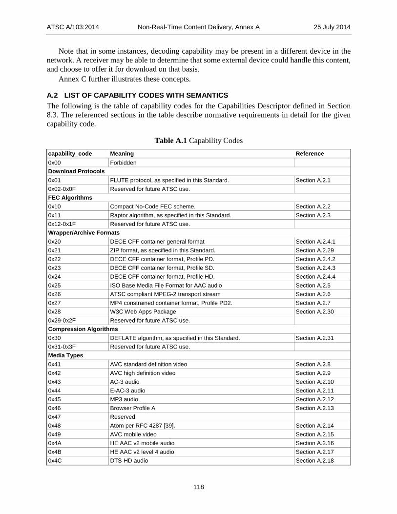
ATSC A/103:2014 Non-Real-Time Content Delivery, Annex A 25 July 2014
118
Note that in some instances, decoding capability may be present in a different device in the network. A receiver may be able to determine that some external device could handle this content, and choose to offer it for download on that basis.
Annex C further illustrates these concepts.
A.2 LIST OF CAPABILITY CODES WITH SEMANTICS The following is the table of capability codes for the Capabilities Descriptor defined in Section 8.3. The referenced sections in the table describe normative requirements in detail for the given capability code.
Table A.1 Capability Codes capability_code Meaning Reference 0x00 Forbidden Download Protocols 0x01 FLUTE protocol, as specified in this Standard. Section A.2.1 0x02-0x0F Reserved for future ATSC use. FEC Algorithms 0x10 Compact No-Code FEC scheme. Section A.2.2 0x11 Raptor algorithm, as specified in this Standard. Section A.2.3 0x12-0x1F Reserved for future ATSC use. Wrapper/Archive Formats 0x20 DECE CFF container general format Section A.2.4.1 0x21 ZIP format, as specified in this Standard. Section A.2.29 0x22 DECE CFF container format, Profile PD. Section A.2.4.2 0x23 DECE CFF container format, Profile SD. Section A.2.4.3 0x24 DECE CFF container format, Profile HD. Section A.2.4.4 0x25 ISO Base Media File Format for AAC audio Section A.2.5 0x26 ATSC compliant MPEG-2 transport stream Section A.2.6 0x27 MP4 constrained container format, Profile PD2. Section A.2.7 0x28 W3C Web Apps Package Section A.2.30 0x29-0x2F Reserved for future ATSC use. Compression Algorithms 0x30 DEFLATE algorithm, as specified in this Standard. Section A.2.31 0x31-0x3F Reserved for future ATSC use. Media Types 0x41 AVC standard definition video Section A.2.8 0x42 AVC high definition video Section A.2.9 0x43 AC-3 audio Section A.2.10 0x44 E-AC-3 audio Section A.2.11 0x45 MP3 audio Section A.2.12 0x46 Browser Profile A Section A.2.13 0x47 Reserved 0x48 Atom per RFC 4287 [39]. Section A.2.14 0x49 AVC mobile video Section A.2.15 0x4A HE AAC v2 mobile audio Section A.2.16 0x4B HE AAC v2 level 4 audio Section A.2.17 0x4C DTS-HD audio Section A.2.18

ATSC A/103:2014 Non-Real-Time Content Delivery, Annex A 25 July 2014
119
capability_code Meaning Reference 0x4D CFF-TT Section A.2.19 0x4E CEA-708 captions Section A.2.20 0x4F HE AAC v2 with MPEG Surround Section A.2.21 0x50 HE AAC v2 Level 6 audio Section A.2.22 0x51 Frame-compatible 3D video (Side-by-Side) Section A.2.23 0x52 Frame-compatible 3D video (Top-and-Bottom) Section A.2.24 0x53-0x5F Reserved for future ATSC use. Internet Link 0x60 Internet link, downward rate 56,000 bps or better Section A.2.25 0x61 Internet link, downward rate 512,000 bps or better Section A.2.26 0x62 Internet link, downward rate 2,000,000 bps or better Section A.2.27 0x63 Internet link, downward rate 10,000,000 bps or better Section A.2.28 0x64-0x6F Reserved for future ATSC use. 0x70-0x7F Available for private use.
A.2.1 Capability Code 0x01: FLUTE Protocol The capability_code value 0x01 shall represent receiver support for the FLUTE protocol as specified in Section 5.2 of the present standard.
A.2.2 Capability Code 0x10: Compact No-Code FEC Scheme The capability_code value 0x10 shall represent the receiver ability to support the “Compact No-
Code FEC scheme” [45] (FEC Encoding ID 0), which shall include: • A receiver for the Compact No-Code FEC scheme such that if a receiver receives all the
source symbols generated according to the FEC code specification in [45] for reconstruction of a source block then the receiver shall recover the entire source block. Note that the Example Receivers described in [45] Clause 3.4.2 fulfills this requirement.
• Recovery of a source block with a maximum size 262,144 bytes. • The FEC Payload ID format as defined in [45] Clause 3.2.1, and • The FEC Object Transmission Information format as defined in [45] Clause 3.2.2.
A.2.3 Capability Code 0x11: Raptor Algorithm The capability_code value 0x11 shall represent the receiver ability to support the“Raptor FEC scheme”[46] (FEC Encoding ID 1), which shall include:
• A decoder for the Raptor FEC scheme such that if a receiver receives a mathematically sufficient set of encoding symbols generated according to the Encoder Specification in [46] for reconstruction of a source block then the decoder shall recover the entire source block. Note that the Example Decoder described in [46] Clause 5.5 fulfills this requirement.
• Decoding of a sub-block with maximum size 262,144 bytes. • The FEC Payload ID format as defined in [46] Clause 3.1, and • The FEC Object Transmission Information format as defined in [46] Clause 3.2.
A.2.4 DECE CFF Multimedia Container Format The DECE Common File Format Specification (CFF) [18] is built on a framework established in the Protected Interoperable File Format (PIFF) [76]. The CFF specification defines a general

ATSC A/103:2014 Non-Real-Time Content Delivery, Annex A 25 July 2014
120
format and three specific Media Profiles – PD for portable devices, SD for standard definition devices and HD for high definition devices.
Tracks in CFF-formatted files (corresponding to capability code values 0x20, and 0x22 through 0x24) might be encrypted. Refer to Section 1.7.3 of CFF [18] for details. The content_security_conditions_indicator in the NRT_information_table_section() shall be used to indicate whether or not a content item includes one or more files that are protected. A.2.4.1. Capability Code 0x20: DECE CFF general format The capability_code value 0x20 shall represent the receiver ability to support the DECE multimedia container format defined in DECE “Common File Format & Media Formats Specification” [18] (excluding the Annexes). This does not imply the ability to support any of the specific content types that can be carried in a file with this format.
This code value shall not be used to describe files conforming to the DECE profiles that are defined in Annexes A-C of the DECE CFF specification [18]. (The three currently defined profiles each have been assigned their own capability code in the sections below.) Use of this code value requires a media type capability code in order to completely describe a file’s content. When the capability code 0x20 is used, at least one media type capability code shall be associated with this code value. A.2.4.2. Capability Code 0x22: PD Media Profile The capability_code value 0x22 shall represent the receiver ability to support the PD Media Profile of the CFF multimedia container format, defined in DECE “Common File Format & Media Formats Specification,” Annex A [18]. This implies the ability to support the DECE CFF general format, the ability to support AVC video with the constraints specified in section A.4 of Annex A, and the ability to support MPEG-4 AAC (2 channel) audio with the constraints specified in section A.5 of Annex A. When this capability code appears along with certain other capability codes, it modifies the specifications defined by those codes, as indicated in the specifications of those capability codes. A.2.4.3. Capability Code 0x23: SD Media Profile The capability_code value 0x23 shall represent the receiver ability to support the SD Media Profile of the CFF multimedia container format defined in DECE “Common File Format & Media Formats Specification,” Annex B [18]. This implies the ability to support the DECE CFF general format, the ability to support AVC video with the constraints specified in section B.4 of Annex B, and the ability to support MPEG-4 AAC (2 channel) audio with the constraints specified in section B.5 of Annex B. When this capability code appears along with certain other capability codes, it modifies the specifications defined by those codes, as indicated in the specifications of those capability codes. A.2.4.4. Capability Code 0x24: HD Media Profile The capability_code value 0x24 shall represent the receiver ability to support the HD Media Profile of the CFF multimedia container format defined in DECE “Common File Format & Media Formats Specification,” Annex C [18]. This implies the ability to support the DECE CFF general format, the ability to support AVC video with the constraints specified in Section C.4 of Annex C, and the ability to support MPEG-4 AAC (2 channel) audio with the constraints specified in Section C.5 of Annex C. When this capability code appears along with certain other capability codes, it modifies the specifications defined by those codes, as indicated in the specifications of those capability codes.

ATSC A/103:2014 Non-Real-Time Content Delivery, Annex A 25 July 2014
121
A.2.5 Capability Code 0x25: ISO Base Media File Format for AAC Audio The capability_code value 0x25 shall represent the receiver ability to support ISO Base Media Files according to [55] and MP4 File Format according to [56] when carrying AAC3 audio [49], constrained as follows:
• The 'moov' box shall be positioned after the 'ftyp' box before the first 'mdat'. If a 'moof' box is present, it shall be positioned before the corresponding 'mdat' box.
• Within a track, chunks shall be in decoding time order within the media-data box 'mdat'. The duration of samples stored in a chunk should not exceed 1 second.
• If the size of 'moov' box becomes bigger than 2.5 Mbytes, the file shall be fragmented by using 'moof' box. The size of 'moov' boxes shall be equal to or less than 2.5 Mbytes. The size of 'moof' boxes shall be equal to or less than 300 Kbytes.
• The sample size box ('stsz') shall be used.The compact sample size box ('stz2') shall not be used.
• The largesize defined in 4.2 of [55] shall not be used. Note that larger MP4 files are still able to be generated and used by means of “fragments.”
• The stco box defined in 8.19 of [55] shall be used. i.e., the 'co64' box defined in Clause 8.19 of [55] shall not be used.
A.2.6 Capability Code 0x26: ATSC Compliant MPEG-2 Transport Stream The capability_code value 0x26 shall represent the receiver ability to support a file that has the format of a sequence of MPEG-2 transport stream packets consisting of all the audio and video packets of one virtual channel (MPEG-2 program) conforming to ATSC A/53 Part 3 [3], Part 4 [4] and Part 5 [5], plus PSI tables (PAT and PMT) describing that program. This capability code implies the ability to parse the MPEG-2 transport stream structure specified in the MPEG-2 systems standard [57] and the ability to decode audio, video and closed captions as specified in A/53.
A.2.7 Capability Code 0x27: PD2 Media Profile The capability_code value 0x27 shall represent the receiver ability to support the PD2 profile of a MP4 [55] file as defined in Annex G.
A.2.8 Capability Code 0x41: AVC Standard Definition Video The capability_code value 0x41 shall represent the receiver ability to support AVC video encoded in conformance with the specifications in A/72 Part 1 [15] for SD resolutions. The capability_code value 0x41 shall not appear along with capability_code values 0x22, 0x23, or 0x24, since each of these code values implies support for AVC with certain specified constraints.
A.2.9 Capability Code 0x42: AVC High Definition Video The capability_code value 0x42 shall represent the receiver ability to support AVC video encoded in conformance with the specifications in A/72 Part 1 [15] for HD resolutions. The capability_code value 0x42 shall not appear along with capability_code values 0x22, 0x23, or 0x24, since each of these code values implies support for AVC with certain specified constraints.
3 The AAC family of codecs includes HE AAC v2 Profile, Level 2 (used for Mobile DTV) and
HE AAC v2 Profile, Level 4 (supporting discrete multichannel), which are identified separately with capability codes 0x4A and 0x4B.

ATSC A/103:2014 Non-Real-Time Content Delivery, Annex A 25 July 2014
122
A.2.10 Capability Code 0x43: AC-3 Audio When capability_code value 0x43 appears along with capability_code value 0x23, it shall represent receiver support for AC-3 audio as constrained in section B.5 of Annex B of the DECE CFF specification [18]. When capability_code value 0x43 appears along with capability_code value 0x24, it shall represent receiver support for AC-3 audio as constrained in section C.5 of Annex C of the DECE CFF specification [18]. When capability_code value 0x43 appears without capability_code values 0x23 or 0x24, it shall represent the receiver ability to support AC-3 audio encoded in conformance with A/53 Part 5 [5].
A.2.11 Capability Code 0x44: Enhanced AC-3 Audio When capability_code value 0x44 appears along with capability_code value 0x23, it shall represent receiver support for Enhanced AC-3 audio as constrained in section B.5 of Annex B of the DECE CFF specification [18]. When capability_code value 0x44 appears along with capability_code value 0x24, it shall represent receiver support for Enhanced AC-3 audio as constrained in section C.5 of Annex C of the DECE CFF specification [18]. When capability_code value 0x44 appears without capability_code values 0x23 or 0x24, it shall represent the receiver ability to support Enhanced AC-3 audio encoded in conformance with A/52 [1], and constrained as specified below. Receivers supporting capability_code value 0x44 also support capability_code 0x43 (AC-3 Audio). A.2.11.1. Enhanced AC-3 Elementary Stream Constraints Enhanced AC-3 elementary streams shall be constrained as follows: data rate – The data rate of an Enhanced AC-3 elementary stream shall be less than or equal to
3024*103 bits/second. fscod – An Enhanced AC-3 elementary stream shall be encoded at a sample rate of 48 kHz, hence
the value of the fscod parameter in all frames of an Enhanced AC-3 elementary stream shall be set to 0x0.
bsid – The value of the bsid parameter in all frames of an Enhanced AC-3 elementary stream shall be set to 0x10.
substreams – An Enhanced AC-3 elementary stream shall always contain at least one independent substream (stream type ‘0’) with a substream ID of ‘0’. An Enhanced AC-3 elementary stream may also additionally contain one dependent substream (stream type ‘1’). The number of substreams shall remain constant for the duration of an Enhanced AC-3 elementary stream.
strmtyp – The value of the strmtyp parameter in all frames of independent substream 0 shall be set to 0x0. The value of the strmtyp parameter in all frames of dependent substream 0, if present, shall be set to 0x1.
substreamid – The value of the substreamid parameter in all frames of an Enhanced AC-3 elementary stream shall be set to 0x0.
acmod – All audio coding modes except dual mono (acmod=’000’) defined in Table 4.3 of ATSC A/52 [1] are permitted. The value of acmod shall remain constant for the duration of an Enhanced AC-3 elementary stream.
lfeon – The value of the lfeon parameter shall remain constant for the duration of an Enhanced AC-3 elementary stream.
chanmap – The value of the chanmap parameter shall remain constant for the duration of an Enhanced AC-3 elementary stream
bsmod - The value of the bsmod parameter shall remain constant for the duration of an Enhanced AC-3 elementary stream.

ATSC A/103:2014 Non-Real-Time Content Delivery, Annex A 25 July 2014
123
A.2.11.2. Substream Configuration for Delivery of More than 5.1 Channels of Audio To deliver more than 5.1 channels of audio, both independent (Stream Type 0) and dependent (Stream Type 1) substreams are included in the Enhanced AC-3 elementary stream. The channel configuration of the complete elementary stream is defined by the “acmod” parameter carried in the independent substream, and the “acmod” and “chanmap” parameters carried in the dependent substream. The loudspeaker locations supported by Enhanced AC-3 are defined in SMPTE 428-3 [78]. The following rules apply to channel numbers and substream use:
• When more than 5.1 channels of audio are to be delivered, independent substream 0 of an Enhanced AC-3 elementary stream shall be configured as a downmix of the complete program.
• Additional channels necessary to deliver up to 7.1 channels of audio shall be carried in dependent substream 0.
A.2.12 Capability Code 0x45: MP3 Audio The capability_code value 0x45 shall represent the receiver ability to support MP3 audio encoded in conformance with ISO/IEC 13818-3 [53].
A.2.13 Capability Code 0x46: Browser Profile A The capability_code value 0x46 shall represent the receiver ability to support all normative requirements of the Browser Profile A-capable Receiver (BPACR) specified in Annex D (page 138).
A.2.14 Capability Code 0x48: Atom The capability_code value 0x48 shall represent the receiver ability to support the Atom syndication format specification RFC 4287 [39].
A.2.15 Capability Code 0x49: AVC Mobile Video The capability_code value 0x49 shall represent the receiver ability to support AVC video encoded in conformance with Section 7 of A/153 Part 7 [10]. The capability_code value 0x49 shall not appear along with capability_code values 0x22, 0x23, or 0x24, since each of these code values implies support for AVC with certain specified constraints.
A.2.16 Capability Code 0x4A: HE AAC v2 Mobile Audio When capability_code value 0x4A appears along with capability_code value 0x22, it shall represent receiver support for HE AAC v2 audio as constrained in section A.5 of Annex A of the DECE CFF specification [18]. When capability_code value 0x4A appears without capability_code value 0x22, it shall represent the receiver ability to support HE AAC v2 audio encoded in conformance with Section 5 of A/153 Part 8 [11].
Sending capability_code value 0x4A along with capability_code value 0x27 is not necessary and is not recommended.
A.2.17 Capability Code 0x4B: HE AAC v2 Profile, Level 4 Audio When capability_code value 0x4B appears along with capability_code value 0x23, it shall represent receiver support for HE AAC v2 5.1 channel audio as constrained in section B.5 of Annex B of the DECE CFF specification [18]. When capability_code value 0x4B appears along with capability_code value 0x24, it shall represent receiver support for HE AAC v2 5.1 channel audio as

ATSC A/103:2014 Non-Real-Time Content Delivery, Annex A 25 July 2014
124
constrained in section C.5 of Annex C of the DECE CFF specification [18]. When capability_code value 0x4B appears without capability_code values 0x23 or 0x24, it shall represent the receiver ability to support HE AAC v2 audio encoded in conformance with HE AAC v2 Profile, Level 4 [49], including, when present, loudness and dynamic range information, i.e., with dynamic_range_info() in the bitstream.
A.2.18 Capability Code 0x4C: DTS-HD Audio When capability_code value 0x4C appears along with capability_code value 0x23, it shall represent receiver support for DTS-HD audio as constrained in section B.5 of Annex B of the DECE CFF specification [18]. When capability_code value 0x4C appears along with capability_code value 0x24, it shall represent receiver support for DTS-HD audio as constrained in section C.5 of Annex C of the DECE CFF specification [18]. When capability_code value 0x4C appears without capability_code value 0x23 or 0x24, it shall represent the receiver ability to support DTS-HD audio encoded in conformance with Reference [20].
A.2.19 Capability Code 0x4D: CFF-TT When the capability_code value 0x4D appears along with capability_code 0x20, it shall represent the receiver ability to support SMPTE Timed Text as constrained in section 6 of the DECE Common File Format and Media Formats Specification [18]. When capability_code value 0x4D appears along with capability_code values 0x22, 0x23 or 0x24, it shall represent the receiver ability to support SMPTE Timed Text as constrained in Annexes A, B and C respectively of the DECE CFF specification [18].
A.2.20 Capability Code 0x4E: CEA 708 Captions The capability_code value 0x4E shall represent the receiver ability to support CEA-708 captions as specified in CEA-708 [16].
A.2.21 Capability Code 0x4F: HE AAC v2 Audio with MPEG Surround The capability_code value 0x4F shall represent the receiver ability to support HE AAC v2 audio with MPEG Surround, as constrained in section A.5 of the DECE CFF specification [18].
A.2.22 Capability Code 0x50: HE AAC v2 Profile, Level 6 Audio When capability_code value 0x50 appears along with capability_code value 0x23, it shall represent receiver support for HE AAC v2 7.1 channel audio as constrained in Section B.5 of Annex B of the DECE CFF specification [18]. When capability_code value 0x50 appears along with capability_code value 0x24, it shall represent receiver support for HE AAC v2 7.1 channel audio as constrained in Section C.5 of Annex C of the DECE CFF specification [18]. When capability_code value 0x50 appears without capability_code values 0x23 or 0x24, it shall represent the receiver ability to support HE AAC v2 audio encoded in conformance with HE AAC v2 Profile, Level 6 [49], including loudness and dynamic range information and DRC Presentation Mode, when present, i.e. with dynamic_range_info() and MPEG4_ancillary_data() in the bitstream.
A.2.23 Capability Code 0x51: 3D video in Side-by-Side format The capability_code value 0x51 shall represent the receiver ability to support display of 3D video in either 720p or 1080i side-by-side format as specified in Section 5.3 of A/104 Part 3 [7]. Since the

ATSC A/103:2014 Non-Real-Time Content Delivery, Annex A 25 July 2014
125
capability_code value 0x51 does not indicate any codec information, it shall be accompanied by other capability_code value such as 0x42 to provide the receivers with the complete information.
A.2.24 Capability Code 0x52: 3D video in Top-and-Bottom format The capability_code value 0x52 shall represent the receiver ability to support display of 3D video in either 720p or 1080p top-and-bottom format as specified in Section 5.2 of A/104 Part 3 [7]. Since the capability_code value 0x52 does not indicate any codec information, it shall be accompanied by other capability_code value such as 0x42 to provide the receivers with the complete information.
A.2.25 Capability Code 0x60: 56 Kbps Internet Connection The capability_code value 0x60 shall represent receiver access to an Internet connection with download rate of 56,000 bps or more.
A.2.26 Capability Code 0x61: 512 Kbps Internet Connection The capability_code value 0x61 shall represent receiver access to an Internet connection with download rate of 512,000 bps or more.
A.2.27 Capability Code 0x62: 56 Kbps Internet Connection The capability_code value 0x62 shall represent receiver access to an Internet connection with download rate of 2,000,000 bps or more.
A.2.28 Capability Code 0x63: 56 Kbps Internet Connection The capability_code value 0x63 shall represent receiver access to an Internet connection with download rate of 10,000,000 bps or more.
A.2.29 Capability Code 0x21: ZIP Format The capability_code value 0x21 shall represent receiver support for the ZIP compression format as specified in Section 5.5 of the present standard.
A.2.30 Capability Code 0x28: W3C Web Apps Package The capability_code value 0x28 shall represent receiver support for the W3C web applications package, as specified in Section 5.5.1 of the present standard.
A.2.31 Capability Code 0x30: DEFLATE Algorithm The capability_code value 0x30 shall represent receiver support for the DEFLATE algorithm [23].

ATSC A/103:2014 Non-Real-Time Content Delivery, Annex B 25 July 2014
126
Annex B: NRT Service Consumption Models
B.1 INTRODUCTION A non-real-time service makes available to a receiver one or more media files. In some cases, files can be retrieved from the broadcast multiplex while the user waits (low latency), while in other cases, the files will be included in the broadcast at a later time. It may be that the receiver can start to retrieve the files immediately but their size and rate of delivery is such that the user will need to return later to view the content after the download completes.
Seven distinct “consumption models” are described in the ATSC NRT standard, each corresponding with a different user experience as the receiver manages the presentation of the files associated with the NRT service. This Annex describes in further detail the seven defined models. Briefly, they are:
• Browse and Download – This type of NRT service describes content that can be selected for later download. One aspect of the user interface involves describing to the user the available content; another involves allowing the user to navigate among previously downloaded content items to make selections for viewing.
• Push – A Push NRT service offers request-based content. Receivers are expected to offer the user a choice whether or not to automatically update content associated with the service. For such services, if the user selects the auto-update option, the receiver caches any service-related content and automatically updates files as new versions are made available. When the user returns to a requested Push service, content that had been pre-loaded is displayed.
• Portal – A Portal NRT service provides an experience similar to a web browser access. Files comprising the textual and graphical elements constituting a web page are made available in the associated FLUTE sessions. The service provider is expected to distribute files associated with Portal services in near-real-time, so that the receiver can build the display while the viewer waits.
• Triggered – A typical use case for the Triggered consumption model is an NRT adjunct service in a audio/video virtual channel delivering synchronized Declarative Objects to enhance the user’s viewing experience. (See the ATSC Interactive Services Standard [69] for a definition of “Declarative Object.”)
• Push Scripted – A typical use case for the Push Scripted consumption model is an NRT service containing a Declarative Object (DO) that is used to provide the “look and feel” for the service, where the DO is delivered too slowly or too infrequently to download it in near real time. It is similar to the Push model in that users are offered a choice whether to auto-update the content associated with the service; if a user accepts, then the DO will launch immediately when the user selects the service in the future.
• Portal Scripted – A typical use case for the Portal Scripted consumption model is an NRT service containing a Declarative Object (DO) that is used to provide the “look and feel” of the service, where the DO is being delivered rapidly and frequently enough to download it in near real time. It is similar to the Portal model in that when a user selects the service, the DO will launch immediately.

ATSC A/103:2014 Non-Real-Time Content Delivery, Annex B 25 July 2014
127
• EPG – An NRT service with the EPG consumption model delivers content items which provide multimedia enhancements for the receiver’s native Electronic Program/Service Guide application. Such an NRT service is not selectable by users. Each content item in such an EPG service can be associated with a virtual channel, an event, or an NRT service (via the Multimedia EPG Linkage Descriptor defined in Section 8.10 of this standard). This allows the EPG application to let a user request additional information about a virtual channel, event, or NRT service, and display the associated content item or items from the EPG service. Such EPG content items could be previews, collections of linked HTML pages, movie posters in image format, etc.
Table B.1 describes some of the characteristics of these seven models, and lists some typical content types and applications.
Table B.1 Typical Expected Content Types and Characteristics of NRT Usage Models
Typical Expected Content Types and Applications
Updates to Certain Content Items May be Offered
Content Provided in Near-Real-Time
Receiver Implementation Defines “Look and Feel” of UI
User Given Choice to “Subscribe” to Service
Browse & Download
A/V—Long-form entertainment programming. A/V—Short-form entertainment programming. A/V—music videos.
No (typically) No Yes No
Push
Text/graphics—news, sports scores, weather, traffic, travel advisories, stock quotes. A/V—short clips (same subjects).
Yes Yes or No Yes Yes
Portal
Text/graphics—broadcaster’s “home” page. Text/graphics—local sports team’s “home” page. Text/graphics—Content provider’s “home” page (for episode or series, for example).
Yes Yes No No
Triggered Declarative objects No (typically) Yes No User can opt out Push Scripted
Declarative object plus others Yes Yes or No No Yes
Portal Scripted
Declarative object plus others Yes Yes No No
EPG Multimedia objects No No N/A N/A
Section B.2 gives a more detailed description of the broadcaster’s intent for receiver handling of content items delivered by NRT services with the different consumption models. Sections B.3 through B.5 give user-centric views of how services with the Browse and Download, Push and Portal consumption models work.

ATSC A/103:2014 Non-Real-Time Content Delivery, Annex B 25 July 2014
128
B.2 CONTENT ITEM HANDLING UNDER DIFFERENT CONSUMPTION MODELS The term “handling” of NRT content items means taking the following actions for the content item(s) in the service at the appropriate times:
• Downloading – retrieving the content item from the broadcast or from an Internet connection, and saving it in local storage of some kind.
• Updating – for content items signaled in the NRT-IT as “updates available,” checking for updates from time to time and downloading the updates as they appear
• Launching/presenting – starting execution in the case of a Declarative Object content item; starting presentation to the user in the case of a passive content item, such as a still image or a video clip
• Suspending/pausing – stopping the execution or presentation of the content item, but maintaining the state of the execution or presentation so that it can be resumed later at the same point
• Resuming – restarting the execution or presentation of a suspended/paused content item at the point where it was suspended/paused
• Closing/exiting – stopping its execution or presentation of the content item, with no preservation of state, so any later restart would start it in its usual initial state
B.2.1 Browse and Download Consumption Model Typically a “Browse and Download” service has multiple content items, but it could have only one.
The broadcaster’s intent for the handling of an NRT service with “Browse and Download” consumption model is:
• Downloading: Allow the user to select which content item(s) in the service are to be downloaded, and download (in the background) only those content items the user has selected.
• Updating: Monitor the downloaded items for updates (in the background), and download updates when they appear.
• Launching/presenting: Allow the user to select for presentation any of the content items which have been successfully downloaded, and launch (or present) a content item only when the user selects it for launching (or presenting).
• Suspending/pausing: Suspend (or pause) a content item when the user indicates it should be suspended.
• Resuming: Resume a suspended content item when the user indicates it should be resumed. • Closing/exiting: Close (or exit) a content item when it “completes” (if that ever happens),
when the user indicates it should be closed , when the user selects another content item in the service for presentation, or when the user leaves the service.
It should be possible for a user to suspend a Browse and Download content item and resume it later, even after the user has left the service and rejoined it.
B.2.2 Push Consumption Model Typically a “Push” service has multiple content items, but it could have only one. The broadcaster’s intent for the handling of an NRT service with “Push” consumption model is:

ATSC A/103:2014 Non-Real-Time Content Delivery, Annex B 25 July 2014
129
• Downloading: When a user selects the service, allow the user to designate content items in the service for auto-update. Download (in the background) the content items designated for auto-update.
• Updating: Monitor and download (in the background) any updates to the content items in the service designated for auto-update, and download any updates that become available.
• Launching/presenting: When the user selects the service, allow the user to launch/present on request any of the content items in the service that are designated for auto-update.
• Suspending/pausing and resuming: Suspend (or pause) and resume a content item only if the player for the content item has its own suspend and resume controls.
• Closing/exiting: Close (or exit) a content item when it “completes” (if that ever happens), when the user indicates it should be closed, when the user selects another content item in the service for presentation, or when the user leaves the service.
B.2.3 Portal Consumption Model A “Portal” service has only a single content item.
The broadcaster’s intent for the handling of an NRT service with “Portal” consumption model is:
• Downloading: When the user selects the service, start downloading the content item immediately.
• Updating: Monitor the content item for updates while the service remains selected. • Launching/presenting: When the user selects the service, launch/present the “entry” file for
the content item as soon as it can be downloaded. • Suspending/pausing and resuming: Suspend (or pause) and resume the content item only
if the player for the content item has its own suspend and resume controls. • Closing/exiting: Close/exit the content item when the user leaves the service.
B.2.4 Triggered Consumption Model A “Triggered” service could have a single content item, or it could have more than one.
A standalone “Triggered” NRT service can be selected directly by a user. An adjunct “Triggered” NRT service can be selected by selecting the virtual channel to which it is an adjunct (enhancement) service.
The broadcaster’s intent for the handling of an NRT service with “Triggered” consumption model is:
• Downloading: When the service is selected, download each content item (TDO) of the service as soon as it is available – where “available” means that the content item has been announced in the NRT-IT, and the current time is within one of the acquisition time slots for the content item. This applies to all content items, whether available via the broadcast, or via the Internet, or both.
• Updating: If an updated version of a content item (TDO) is available in the service while the service is selected, download the update.
The expected launch, suspend, resume and exit behavior of a TDO is described in the section of A/105 [69] defining the TDO lifecycle.

ATSC A/103:2014 Non-Real-Time Content Delivery, Annex B 25 July 2014
130
B.2.5 Push Scripted Consumption Model A “Push Scripted” service typically has multiple content items, one of which is signaled as the “master” content item. See the master_item field in Section 6.3.
The broadcaster’s intent for the handling of an NRT service with “Push Scripted” consumption model is:
• Downloading: Allow the user to designate the service for auto-update. When the user has designated the service for auto-update, download (in the background) the “master” content item.
• Updating: When the user has designated the service for auto-update, monitor the “master” content item for updates (in the background), and download any updates that become available.
• Launching/presenting: When the service has been designated for auto-update and is subsequently selected, launch (or present) the “master” content item.
• Suspending/pausing and resuming: If the “master” content item is an NRT Declarative Object (NDO), its suspend and resume behavior is described in the section of [the ATSC 2.0 standard] defining the NDO lifecycle. Otherwise, suspend (or pause) and resume a content item only if the player for the content item has its own suspend and resume controls.
• Closing/exiting: Close/exit the “master” content item when the user leaves the service.
B.2.6 Portal Scripted Consumption Model A “Portal Scripted” service typically has multiple content items, one of which is signaled as the “master” content item. See the master_item field in Section 6.3.
The broadcaster’s intent for the handling of an NRT service with “Portal Scripted” consumption model is:
• Downloading: Download the “master” content item for the service when the service is selected.
• Updating: Monitor the “master” content item for updates while the service remains selected, and download any updates that appear.
• Launching/presenting: When the service is selected, launch (or present) the entry file of the “master” content item as soon as it is downloaded.
• Suspending/pausing and resuming: If the “master” content item is an NRT Declarative Object (NDO), its suspend and resume behavior is described in the section of A/105 [69] defining the NDO lifecycle. Otherwise, suspend (or pause) and resume a content item only if the player for the content item has its own suspend and resume controls..
• Resuming: Resume the suspended “master” content item when the user indicates it should be resumed.
• Closing/exiting: Close/exit the “master” content item when the user leaves the service.
B.2.7 EPG Consumption Model The broadcaster’s intent for the handling of an NRT service with EPG Consumption Model is: • Downloading: For content items in an EPG service that are available only via the broadcast,
download and save the EPG content items in the background, for presentation when requested by a viewer using the Program Guide. For content items in an EPG service that are available via the Internet, either download and save the EPG content items in the

ATSC A/103:2014 Non-Real-Time Content Delivery, Annex B 25 July 2014
131
background for presentation when requested by a viewer using the Program Guide, or download the EPG content items via the Internet in real time when requested by a viewer using the Program Guide. In cases when EPG content items are being downloaded and saved in the background, the receiver could impose various types of limits on the number of virtual channels, events, and/or NRT services for which EPG content items are saved at any one time
• Updating: If EPG content items are being downloaded and saved in the background, then monitor the EPG service in the background for updates, and update saved EPG content items when updated versions appear in the EPG service.
• Launching/presenting: Launch/present an EPG content item when requested by the native EPG application (typically when a user viewing the content guide indicates a desire to get more information about the virtual channel, event or NRT service to which that EPG content item is linked).
• Suspending: EPG content items cannot be suspended (other than by suspend operations within the presentation engine for the content item – e.g., a “pause” operation when the EPG content item is a video clip).
• Resuming: Since EPG content items cannot be suspended, they cannot be resumed. • Closing/exiting: Close/exit an EPG content item when the EPG application closes it
(typically when a user indicates it should be closed, or when the user highlights a different virtual channel, event, NRT service or NRT content item in the Program Guide, or when the user exits the Program Guide).
B.3 BROWSE AND DOWNLOAD The “look and feel” of the Browse and Download NRT service is completely determined by the receiver manufacturer. A wide variety of implementations are possible, ranging from the very simple to the elegantly sophisticated. There are two basic operations expected to be supported by the receiver’s user interface to the Browse and Download service: the function whereby the user browses for content to be retrieved from the digital broadcast, and the function wherein he or she chooses to view previously downloaded content.
In the Browse and Download NRT service, content is typically delivered slower than real-time. Content formats typically are audio/video, but can also be audio-only or websites, which are declarative content such as would be displayed by a web browser, possibly with embedded audio/video elements in addition to text and graphics.
The Browse and Download NRT service is best for offerings of long-form entertainment programming such as past episodes of an episodic series, although shorter-form content may be offered as well.
B.3.1 Browsing For Content A receiver is expected to present a Browse and Download type of NRT service by first offering to the user a list of the available content titles associated with the service. The user interface is expected to involve the display of descriptive information about each content item, such as title and description, parental rating (if available), language, captioning information (when available), playback time, and genre (when provided). The user may interact with the receiver to browse amongst available titles, and (if the receiver supports it), perform search and/or filter operations on the metadata.

ATSC A/103:2014 Non-Real-Time Content Delivery, Annex B 25 July 2014
132
The user may select one or more available content items for download and later viewing. Items so selected may be labeled graphically with a symbol indicating “selected for download,” or may be deleted from the selection list once chosen.
Figure B.1 shows an example user interface to illustrate the concept. The graphic at the upper left was provided as a service icon. At the left is a list of content titles available for selection. When the user highlights a title, in this case “Wild Stickleberries,” details about the program or episode are shown at the right. The user can highlight the “SELECT” button and, if activated, cause this episode to be scheduled for download. In this example, additional episodes of the same program may be browsed by using the right arrow on the remote.
Select Content to Download
The Big Blue HelpKids Pick the Attorney General National Day of Play Just Add VodkaJake & DrakeWild StickleberriesPlanet TwinkleBananaman LivesDanger SquirrelFlub BrothersInspector Widget
The commvee is falling apart and an Aye-Aye found inside is hunted and thought to be the cause.
(PG) CC
Luck Be an Aye-Aye (orig. air:2/15/2000)
More Episodes
SELECT
Figure B.1 Example content selection UI.
Many other types and formats of user interface are possible when implementing the content selection function. NRT content can be integrated with other program guide data, for example, so that a search can yield both linear as well as NRT programming.
B.3.2 Selecting Content for Viewing A second user interface aspect of the Browse and Download NRT service is the function which allows selection of previously-downloaded content for playback. This function is analogous to the TiVo™ “Now Playing” screen. The user is given the opportunity to select an item for playback, scrolling through a number of pages as necessary. Typically, through a secondary screen or pop-up window, detailed information about a given item may be viewed. Such information could include (in addition to title and description):
• An icon descriptive of the content (such as a thumbnail JPEG or PNG graphic) • Other selection-related metadata (genre, content advisory, captioning info, language, etc.) • Playback time • Date originally downloaded (or age in days) • Storage requirements (or percentage of available disk space the content occupies) Note that in some instances, playback may start before the whole file is retrieved. Metadata
available to the receiver includes a parameter letting the receiver know how much time to wait following retrieval of the first byte of the file before playback may begin. Starting earlier than the recommended time would likely cause buffer underflow, and a pause in playback. Note that while
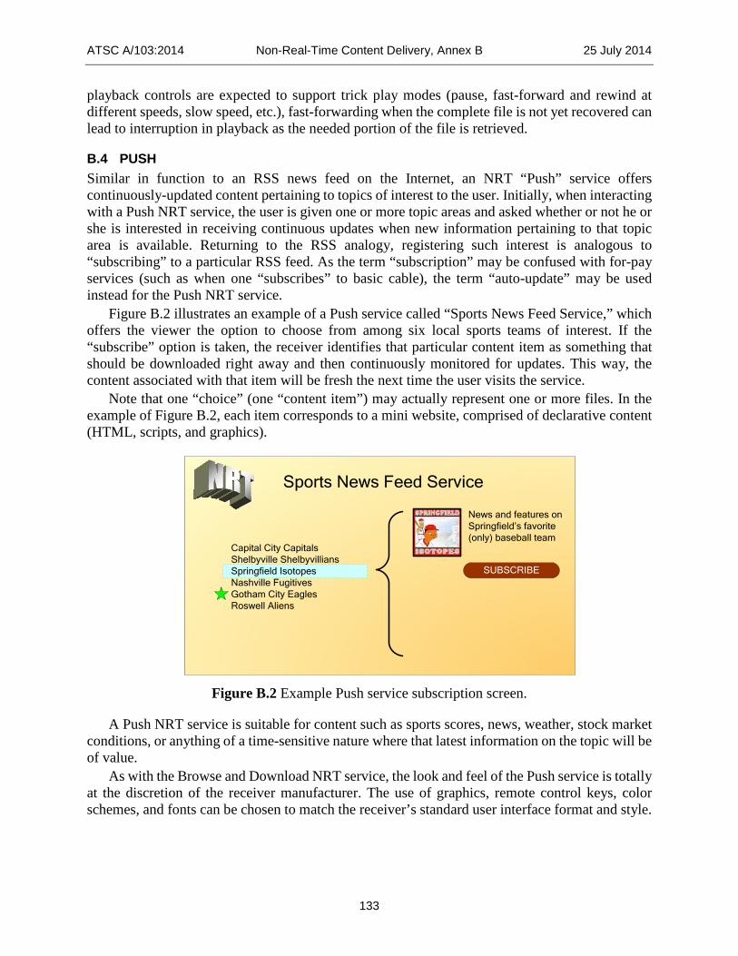
ATSC A/103:2014 Non-Real-Time Content Delivery, Annex B 25 July 2014
133
playback controls are expected to support trick play modes (pause, fast-forward and rewind at different speeds, slow speed, etc.), fast-forwarding when the complete file is not yet recovered can lead to interruption in playback as the needed portion of the file is retrieved.
B.4 PUSH Similar in function to an RSS news feed on the Internet, an NRT “Push” service offers continuously-updated content pertaining to topics of interest to the user. Initially, when interacting with a Push NRT service, the user is given one or more topic areas and asked whether or not he or she is interested in receiving continuous updates when new information pertaining to that topic area is available. Returning to the RSS analogy, registering such interest is analogous to “subscribing” to a particular RSS feed. As the term “subscription” may be confused with for-pay services (such as when one “subscribes” to basic cable), the term “auto-update” may be used instead for the Push NRT service.
Figure B.2 illustrates an example of a Push service called “Sports News Feed Service,” which offers the viewer the option to choose from among six local sports teams of interest. If the “subscribe” option is taken, the receiver identifies that particular content item as something that should be downloaded right away and then continuously monitored for updates. This way, the content associated with that item will be fresh the next time the user visits the service.
Note that one “choice” (one “content item”) may actually represent one or more files. In the example of Figure B.2, each item corresponds to a mini website, comprised of declarative content (HTML, scripts, and graphics).
Sports News Feed Service
Capital City CapitalsShelbyville ShelbyvilliansSpringfield Isotopes Nashville FugitivesGotham City EaglesRoswell Aliens
News and features on Springfield’s favorite (only) baseball team
SUBSCRIBE
Figure B.2 Example Push service subscription screen.
A Push NRT service is suitable for content such as sports scores, news, weather, stock market conditions, or anything of a time-sensitive nature where that latest information on the topic will be of value.
As with the Browse and Download NRT service, the look and feel of the Push service is totally at the discretion of the receiver manufacturer. The use of graphics, remote control keys, color schemes, and fonts can be chosen to match the receiver’s standard user interface format and style.

ATSC A/103:2014 Non-Real-Time Content Delivery, Annex B 25 July 2014
134
B.5 PORTAL A Portal NRT service is intended to offer an experience similar to browsing the Internet using a web browser. Unlike the Browse & Download and Push NRT services, content offered via a Portal service is made available with low latency: once selected, the user need not wait very long before content is retrieved from the broadcast multiplex and rendered onscreen.
Also unlike the other two categories, the on-screen appearance of the content provided in a Push service is defined by the declarative content itself. As with a typical web browser, the receiver may offer the user options such as font size and zoom controls, but the layout of text and graphics is defined by the content creator.
The ATSC NRT standard defines a “browser profile” that NRT-capable receivers are expected to implement. This profile establishes specific capabilities for support of media formats including specific features of HTML, EcmaScript, cascading style sheets, document object models, graphics objects, and many other factors.
The Portal service can be equated to a mini-website. As mentioned, an item of content within an NRT service corresponds to one or more files. Whenever an item of content includes more than one file, one will be labeled as the “entry” point. Declarative content consisting of HTML, scripts, and graphics would likely label one of the HTML files as the entry point (like an “index.html” file). As the receiver processes the entry point file, references to other files (such as graphics objects, or to other HTML pages via hyperlinks) may be encountered.
Figure B.3 depicts an example NRT Portal service that is the home page of a hypothetical broadcaster called WMM as it might be rendered on a widescreen DTV display.
Figure B.3 Portal page example.

ATSC A/103:2014 Non-Real-Time Content Delivery, Annex B 25 July 2014
135

ATSC A/103:2014 Non-Real-Time Content Delivery, Annex C 25 July 2014
136
Annex C: Capability Code Signaling Example
C.1 SCOPE The signaling mechanisms defined in this Standard are designed to allow delivery of a wide variety of media formats, including formats not listed or anticipated at the time of publication of the Standard. This Annex provides an illustrative example of an NRT service that includes such components, and shows how the content provider can control whether or not certain content items described as part of a service are offered to the user. The example also illustrates the principle that the metadata describing content and services must be sufficient to prevent a situation where the user is offered the opportunity to download a content item that cannot be rendered, or that (if rendered) produces an unacceptable user experience.
C.2 EUROPEAN TRAVEL DESTINATION NRT SERVICE EXAMPLE In this example, an NRT “browse and download” service is offered. The details are as follows:
Table C.1 Example Service Description Service Name: “European Travel Destinations” NRT Service Category: Browse & Download Capability Codes: “Browser Profile A” Content: A “mini website” for each of three different destinations, Greece, France, and Turkey.
The content items offered with this service consist of the following. Note: the example refers to a fictitious codec called “MagicFlow”:
Table C.2 Example Content Description Content Item Name: “Greece”
• ZIP file containing several HTML pages, many JPEG images • Consists of text and graphics with travel information for Greece, a page on rail transportation, a page on
food, a page on lodging, etc. • NRT-IT Capabilities Descriptors: none
Content Item Name: “France” • ZIP file containing several HTML pages, many JPEG images, and ES (ECMAScript) files • Consists of text and graphics with travel information for France, a page on rail transportation, a page on
food, a page on lodging, etc. • Includes an animated flag on the masthead of the home page, using a Magicflow plug-in (Content-
Type=application/x-magicflow) • NRT-IT Capabilities Descriptors: none
Content Item Name: “Turkey” • ZIP file containing several HTML, JPEG images, and ES (ECMAScript) files • Consists primarily of a Magicflow slide show of travel destinations in Turkey, with accompanying text and
fixed graphics • NRT-IT Capabilities Descriptor: video/x-magicflow
Any receiver that can handle Browser Profile A is expected to offer the “European Travel Destinations” service to the user (all receivers are expected to support Browser Profile A). A receiver that does not recognize Media Type “video/x-magicflow” is expected to NOT offer “Turkey”

ATSC A/103:2014 Non-Real-Time Content Delivery, Annex C 25 July 2014
137
as an available content item. Such a receiver, when rendering “France” is expected to process the script associated with the Magicflow plug-in, and act accordingly, meaning that it will gracefully discard aspects of the content it does not recognize or support. In this example, depending upon how the script is authored, the site may cause a fixed graphic to be rendered in the area that the waving flag would have occupied.
Table C.3 illustrates the behavior of these two receivers.
Table C.3 Receiver Behavior Receiver #1 Receiver #2 Supports Browser Profile A Yes Yes Supports Media Type video/x-magicflow Yes No Offers “Greece” Yes Yes Offers “France” Yes Yes
• Displays animated waving flag: Yes No Offers “Turkey” Yes No

ATSC A/103:2014 Non-Real-Time Content Delivery, Annex D 25 July 2014
138
Annex D: “Browser Profile A” Specification
D.1 SCOPE This establishes the normative definition of “Browser Profile A,” corresponding to capability_code value 0x46.
D.2 BROWSER PROFILE A Browser Profile A is defined as a list of required capabilities that, when implemented in an NRT receiver, allow it to properly render declarative content created for such receivers. The protocols specified here are derived from or normative references to CEA-2014 [17], a standard for a suite of client/server protocols for Remote User Interface (RUI). CEA-2014 specifies requirements for an RUI client in which client/server interactions are specified. In the NRT application, the client is only responsible for rendering the content provided in one or more files. Therefore, only the portions of CEA-2014 pertaining to declarative content formats and features are cited here.
A receiver capable of supporting Browser Profile A shall be considered a BPACR (Browser Profile A-capable receiver). The following sections specify mandatory requirements for the BPACR.
D.2.1 CE-HTML The BPACR shall support the subset of the “CE-HTML-1.0”protocol specified in CEA-2014 Sections 5.4 through 5.10 specified in the following sections. D.2.1.1. XHTML The BPACR shall support XHTML 1.0 Strict or Transitional as specified in CEA-2014 Section 5.4 item 1). Content authored in accordance with Browser Profile A shall conform with XHTML authoring guidelines C.8 of [65]. D.2.1.2. ECMA-262 The BPACR shall support ECMA-262 scripting language as specified in CEA-2014 Section 5.4 item 2).

ATSC A/103:2014 Non-Real-Time Content Delivery, Annex D 25 July 2014
139
media transport
XHTML content
in scope interface
NRR
out of scope interface
UI Shell
XHTML BrowserUser inputHandler
A/V Playback
Javascript binding
Javascript binding
Bookmarks
Profiles
Parental Control Agent
optional
Figure D.1 XHTML browser block diagram.
D.2.1.3. DOM 2 The BPACR shall support Document Object Model Level 2 Specification, including mandatory support for the ECMAScript language bindings specified in CEA-2014 Section 5.4 item 3). D.2.1.4. ECMAScript Direct Access The BPACR shall support ECMAScript direct access as specified in CEA-2014 Section 5.4 item 5). D.2.1.5. CSS The BPACR shall support Cascading Style Sheets 2.1 as specified in CEA-2014 Section 5.4 item 7). D.2.1.6. Graphics The BPACR shall support graphics objects in GIF, PNG, and JPG formats as specified in CEA-2014 Section 5.4 item 8). D.2.1.7. Tagged Opcodes Replacement The BPACR shall support tagged opcodes replacement as specified in CEA-2014 Section 5.4 item 9). D.2.1.8. data:// Uri Scheme The BPACR shall support the data:// URI scheme as specified in CEA-2014 Section 5.4 item 10). D.2.1.9. Key Events The BPACR shall support key events as specified in CEA-2014 Section 5.4.1. D.2.1.10. Cookie Support The BPACR shall support cookies as specified in CEA-2014 Section 5.9.

ATSC A/103:2014 Non-Real-Time Content Delivery, Annex D 25 July 2014
140
D.2.1.11. Robustness The BPACR shall support requirements for the Remote UI Client pertaining to robustness as specified in CEA-2014 Section 5.10.
D.2.2 User Interface Profile CEA-2014 establishes a communication protocol whereby the RUI Server can learn the capabilities of an RUI Client by a “capability exchange.” The BPACR shall implement at least the minimum functionalities specified for the UI Profile “FULHD_UIPROF” specified in CEA-2014 Section 5.2. These include:
• A maximum width of the browser area corresponding to the full width of the display screen. • A maximum height of the browser area corresponding to the full width of the display
screen. • A color depth of at least 65,536 colors (“high” color). • Support for Tiresias Screenfont font with a default font size of 36 points. • Support for Letter Gothic 12 Pitch font with a default font size of 36 points. • Inclusion of and support for navigation keys on the remote control unit (up, down, left,
right, and ENTER). • Inclusion of and support for numeric keys on the remote control unit.
D.2.3 Optional Elements Support for the following items is optional. D.2.3.1. Window Scripting Object The BPACR may or may not support window scripting methods and properties as defined in CEA-2014 Section 5.4.2. D.2.3.2. In-Session Notifications The BPACR may or may not support the in-session notification methods defined in CEA-2014 Section 5.5. D.2.3.3. Third-Party Notifications The BPACR may or may not support the third-party notification methods defined in CEA-2014 Section 5.6. D.2.3.4. A/V Playback and Control The BPACR may or may not support the A/V playback and control methods defined in CEA-2014 Section 5.7. D.2.3.5. Save and Restore The BPACR may or may not support the save and restore mechanism referenced in CEA-2014 Section 5.8. D.2.3.6. Control Ownership The BPACR may or may not support the control ownership mechanism referenced in CEA-2014 Section 5.11.

ATSC A/103:2014 Non-Real-Time Content Delivery, Annex D 25 July 2014
141
D.2.3.7. Home Network Framework The BPACR may or may not support the home network framework referenced in CEA-2014 Section 5.12. D.2.3.8. Scalable Vector Graphics (SVG) The BPACR may or may not support web-pages containing or referencing Scalable Vector Graphics (SVG) documents as specified in CEA-2014 Section 5.15. D.2.3.9. Connection Handler The BPACR may or may not include a connection handler to support discovery and setup/control requests from a third-party remote UI control point inside a UPnP network. D.2.3.10. UI Shell The BPACR may or may not implement UI shell functionality (used to show the available UIs that are discovered within the network). D.2.3.11. Download Agent The BPACR may or may not implement a download agent for downloading content onto local storage available to the Remote UI client. D.2.3.12. DRM Agent The BPACR may or may not implement a DRM agent for managing licenses to play back (downloaded) content protected by Digital Rights Management. D.2.3.13. Authentication and Authorization The BPACR may or may not implement authentication and authorization to protect unwanted access to local device APIs made available to Remote UIs through ECMAScript. D.2.3.14. Parental Control Agent The BPACR may or may not implement a parental control agent to interchange data with the parental rating control functionality.
D.2.4 Summary Table D.1 is provided as an informative reference to illustrate the relationship between the BPACR and a CEA-2014 client in terms of optional and required elements. The listed functionalities refer to Section 4.5.1 of CEA-2014-B.

ATSC A/103:2014 Non-Real-Time Content Delivery, Annex D 25 July 2014
142
Table D.1 Required and Optional Functionality for BPACR (Informative)
Functionality Required/Optional
CEA-2014 BPACR 1. XHTML Browser Required Required 2. Connection Handler Optional Optional 3. User Input Handler Required Required 4. Event/Notification Handler Required Optional 5. 3rd Party Notification Handler Required Optional 6. UI Shell Required Optional 7. A/V Playback Optional Optional 8. Save-Restore Handler Optional Optional 9. Download Agent Optional Optional 10. DRM Agent Optional Optional 11. Home Network Control Optional Optional 12. Control Ownership Optional Optional 13. Authentication and Authorization Optional Optional 14. Parental Control Agent Optional Optional
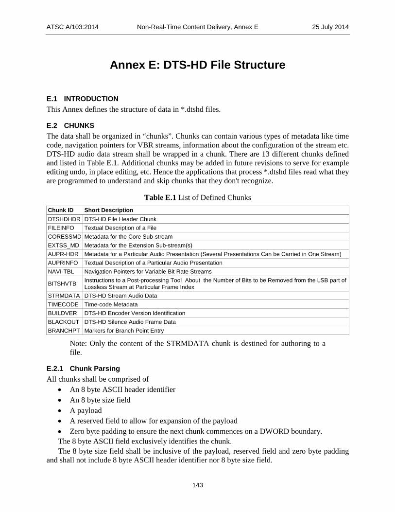
ATSC A/103:2014 Non-Real-Time Content Delivery, Annex E 25 July 2014
143
Annex E: DTS-HD File Structure
E.1 INTRODUCTION This Annex defines the structure of data in *.dtshd files.
E.2 CHUNKS The data shall be organized in “chunks”. Chunks can contain various types of metadata like time code, navigation pointers for VBR streams, information about the configuration of the stream etc. DTS-HD audio data stream shall be wrapped in a chunk. There are 13 different chunks defined and listed in Table E.1. Additional chunks may be added in future revisions to serve for example editing undo, in place editing, etc. Hence the applications that process *.dtshd files read what they are programmed to understand and skip chunks that they don't recognize.
Table E.1 List of Defined Chunks Chunk ID Short Description DTSHDHDR DTS-HD File Header Chunk FILEINFO Textual Description of a File CORESSMD Metadata for the Core Sub-stream EXTSS_MD Metadata for the Extension Sub-stream(s) AUPR-HDR Metadata for a Particular Audio Presentation (Several Presentations Can be Carried in One Stream) AUPRINFO Textual Description of a Particular Audio Presentation NAVI-TBL Navigation Pointers for Variable Bit Rate Streams
BITSHVTB Instructions to a Post-processing Tool About the Number of Bits to be Removed from the LSB part of Lossless Stream at Particular Frame Index
STRMDATA DTS-HD Stream Audio Data TIMECODE Time-code Metadata BUILDVER DTS-HD Encoder Version Identification BLACKOUT DTS-HD Silence Audio Frame Data BRANCHPT Markers for Branch Point Entry
Note: Only the content of the STRMDATA chunk is destined for authoring to a file.
E.2.1 Chunk Parsing All chunks shall be comprised of
• An 8 byte ASCII header identifier • An 8 byte size field • A payload • A reserved field to allow for expansion of the payload • Zero byte padding to ensure the next chunk commences on a DWORD boundary. The 8 byte ASCII field exclusively identifies the chunk. The 8 byte size field shall be inclusive of the payload, reserved field and zero byte padding
and shall not include 8 byte ASCII header identifier nor 8 byte size field.

ATSC A/103:2014 Non-Real-Time Content Delivery, Annex E 25 July 2014
144
E.2.2 Chunk Order and Navigation The DTSHDHDR chunk shall be the first chunk in the file. The remaining chunks can occur in any order.
Applications that open .dtshd files shall check for the presence of “DTSHDHDR” in the first 8 bytes of the file.
After finding the DTSHDHDR keyword, the next 8 byte field that indicates the size of DTSHDHDR chunk (Hdr_Byte_Size Bytes) shall be read. The search for a particular chunk shall begin:
• First the DTSHDHDR chunk shall be skipped by traversing Hdr_Byte_Size bytes forward. • Next the 8-byte ASCII chunk header identifier, found at the first 8-byte filed of the second
chunk, shall be compared to the desired chunk keyword and if they are matching we have found our desired chunk.
• If the match is not established the next 8-byte filed that indicates the size of a current chunk (Curr_Chunk_Byte_Size) is read, and then skip to the next chunk by traversing forward by Curr_Chunk_Byte_Size bytes. This procedure shall be repeated until desired ASCII chunk header identifier is found.
E.2.3 Chunk Notation The following notation is used.
• ASCII indicates ASCII coded 8-bit characters • uintNB indicates N-Byte unsigned integers in the range from 0 to 2N*8 – 1 • barray2B indicates a 2-Byte array where each bit is treated as a Boolean variable
E.2.4 DTSHDHDR This shall be the first chunk in a .dtshd formatted file.
Table E.2 DTS-HD File Organization Item No. of Bytes Description “DTSHDHDR” Keyword 8 Bytes ASCII Hdr_Byte_Size 8 Bytes uint8B Hdr_Version 4 Bytes uint4B Time_Code 5 Bytes uint5B TC_Frame_Rate 1 byte uint1B Bitw_Stream_Metadata 2 Bytes barray2B Num_Audio_Presentations 1 Byte uint1B Number_Of_Ext_Sub_Streams 1 Byte uint1B End Of DTSHDHDR Header Reserved unspecified number Bytes unspecified type Dword_Align 1, 2, or 3 Bytes Filled with 0’s
The time code data shall be a 40-bit field composed as follows:

ATSC A/103:2014 Non-Real-Time Content Delivery, Annex E 25 July 2014
145
Table E.3 Time Code Data Bits 39 to 38 Bits 32 to 37 Bits 0 to 31 RefClockCode Reserved TimeStamp
Table E.4 Reference Clock Period RefClockCode Clock (Hz) 0 32000.0 1 44100.0 2 48000.0 3 reserved
The TimeStamp value represents the sample count since midnight. This number is a function of the elapsed time and the sample frequency as indicated by (RefClockCode) from Table E.3. The equation for conversion of the number of video frames to the TimeStamp value shall be
=
*NumVideoFrames clockTimeStamp floorVideoRate
Where NumVideoFrames is the timecode expressed as the frame count since midnight, clock shall be the value of the timecode sample rate as indicated in Table E.3 and the VideoRate shall be 23.976, 24, 25, 29.97 or 30 frames per second. Since DTSHD files have a constant delay of two frames the TimeStamp corresponds to the start of the first sample obtained by decoding the third frame in the file.
The TC_Frame_Rate field shall be composed as follows:
Table E.5 TC_Frame_Rate Code TC_Frame_Rate Timecode Rate xxxx 0000 NOT_INDICATED xxxx 0001 23.97602398… xxxx 0010 24.0 xxxx 0011 25.0 xxxx 0100 29.97002997… DROP xxxx 0101 29.97002997… xxxx 0110 30.0 DROP xxxx 0111 30.0 xxxx 1000 to xxxx 1111 RESERVED
The Bitw_Stream_Metadata field shall be composed as follows:

ATSC A/103:2014 Non-Real-Time Content Delivery, Annex E 25 July 2014
146
Table E.6 Bitw_Stream_Metadata Bit Fields Syntax Field Description Bit Location Constant bit-rate (CBR) or variable bit-rate (VBR) stream descriptor: - CBR if FALSE - VBR if TRUE
0x0001
Peak bit rate smoothing (PBRS) indicator: - PBRS has not been performed if FALSE - PBRS has been performed if TRUE
0x0002
Navigation table indicator: - navigation data is not embedded in the header if FALSE - navigation data is embedded in the header if TRUE
0x0004
Presence of a core sub-stream: - Not present if FALSE - Present if TRUE
0x0008
Presence of an extension sub-stream(s): - Not present if FALSE - Present if TRUE
0x0010
Reserved 0x0020 – 0x8000
A DTS-HD stream may consist of core sub-stream and/or up to four extension sub-streams. The actual number of extension sub-streams (Num_ExSS) present in the stream shall be calculated as follows:
if ( (Bitw_Stream_Metadata & 0x0010) == TRUE) Num_ExSS = Number_Of_Ext_Sub_Streams + 1 else Num_ExSS = 0
E.2.5 FILEINFO Contains abbreviated textual information regarding the file that in certain OS’s shall be of value in a popup window.
Table E.7 FILEINFO Metadata Item No. of Bytes Description “FILEINFO” Keyword 8 Bytes ASCII FILEINFO_Text_Byte_Size 8 Bytes uint8B A null terminated ASCII string containing a textual description of the file. (i.e., VBR or CBR file; Primary and/or Secondary Audio …) ASCII
Reserved unspecified number Bytes
unspecified type
Dword_Align 1, 2, or 3 Bytes Filled with 0’s
E.2.6 CORESSMD
Table E.8 Core Sub-Stream Metadata Item No. of Bytes Description “CORESSMD” Keyword 8 Bytes ASCII Core_Ss_Md_Bytes_Size 8 Bytes uint8B Core_Ss_Max_Sample_Rate_Hz 3 Bytes uint3B
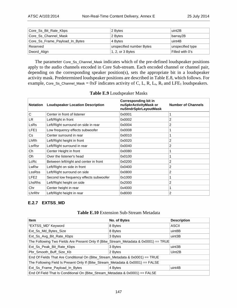
ATSC A/103:2014 Non-Real-Time Content Delivery, Annex E 25 July 2014
147
Core_Ss_Bit_Rate_Kbps 2 Bytes uint2B Core_Ss_Channel_Mask 2 Bytes barray2B Core_Ss_Frame_Payload_In_Bytes 4 Bytes uint4B Reserved unspecified number Bytes unspecified type Dword_Align 1, 2, or 3 Bytes Filled with 0’s
The parameter Core_Ss_Channel_Mask indicates which of the pre-defined loudspeaker positions apply to the audio channels encoded in Core Sub-stream. Each encoded channel or channel pair, depending on the corresponding speaker position(s), sets the appropriate bit in a loudspeaker activity mask. Predetermined loudspeaker positions are described in Table E.8, which follows. For example, Core_Ss_Channel_Mask = 0xF indicates activity of C, L, R, Ls, Rs and LFE1 loudspeakers.
Table E.9 Loudspeaker Masks
Notation Loudspeaker Location Description Corresponding bit in nuSpkrActivityMask or nuStndrSpkrLayoutMask
Number of Channels
C Center in front of listener 0x0001 1 LR Left/Right in front 0x0002 2 LsRs Left/Right surround on side in rear 0x0004 2 LFE1 Low frequency effects subwoofer 0x0008 1 Cs Center surround in rear 0x0010 1 LhRh Left/Right height in front 0x0020 2 LsrRsr Left/Right surround in rear 0x0040 2 Ch Center Height in front 0x0080 1 Oh Over the listener's head 0x0100 1 LcRc Between left/right and center in front 0x0200 2 LwRw Left/Right on side in front 0x0400 2 LssRss Left/Right surround on side 0x0800 2 LFE2 Second low frequency effects subwoofer 0x1000 1 LhsRhs Left/Right height on side 0x2000 2 Chr Center height in rear 0x4000 1 LhrRhr Left/Right height in rear 0x8000 2
E.2.7 EXTSS_MD
Table E.10 Extension Sub-Stream Metadata Item No. of Bytes Description “EXTSS_MD” Keyword 8 Bytes ASCII Ext_Ss_Md_Bytes_Size 8 Bytes uint8B Ext_Ss_Avg_Bit_Rate_Kbps 3 Bytes uint3B The Following Two Fields Are Present Only If (Bitw_Stream_Metadata & 0x0001) == TRUE Ext_Ss_Peak_Bit_Rate_Kbps 3 Bytes uint3B Pbr_Smooth_Buff_Size_Kb 2 Bytes Uint2B End Of Fields That Are Conditional On (Bitw_Stream_Metadata & 0x0001) == TRUE The Following Field Is Present Only If (Bitw_Stream_Metadata & 0x0001) == FALSE Ext_Ss_Frame_Payload_In_Bytes 4 Bytes uint4B End Of Field That Is Conditional On (Bitw_Stream_Metadata & 0x0001) == FALSE

ATSC A/103:2014 Non-Real-Time Content Delivery, Annex E 25 July 2014
148
Reserved unspecified number Bytes unspecified type Dword_Align 1, 2, Or 3 Bytes Filled with 0’s
All Num_ExSS extension sub-streams, that are present in the stream, are described together as group using the EXTSS_MD chunk. Consequently:
• The Ext_Ss_Avg_Bit_Rate_Kbps is the average bit rate of data in all extension sub-streams together.
• The Ext_Ss_Frame_Payload_In_Bytes this field exist only for the constant bit rate (CBR) streams and it indicates the frame payload of all extension sub-stream frame payloads added together.
• The Ext_Ss_Peak_Bit_Rate_Kbps this field exists only for the variable bit rate streams (VBR) and it indicates the peak data rate when considering all extension sub-streams coexisting together. Note that even in the case when only one of the extension sub-streams is VBR and all others are CBR the stream is considered to be VBR.
E.2.8 AUPR-HDR
Table E.11 Audio Presentation Header Metadata Item No. of Bytes Description “AUPR-HDR” Keyword 8 Bytes ASCII Audio_Pres_Hdr_Md_Bytes_Size 8 Bytes uint8B Audio_Pres_Index 1 Bytes uint1B Bitw_Aupres_Metadata 2 Bytes barray2B Max_Sample_Rate_Hz 3 Bytes uint3B Num_Frames_Total 4 Bytes uint4B Samples_Per_Frame_At_Max_Fs 2 Bytes uint2B Num_Samples_Orig_Audio_At_Max_Fs 5 Bytes uint5B Channel_Mask 2 Bytes barray2B Codec_Delay_At_Max_Fs 2 Bytes uint2B The Following Three Fields Are Present Only If (Bitw_Aupres_Metadata & 0x0003) == 3 BC_Core_Max_Sample_Rate_Hz 3 Bytes uint3B BC_Core_Bit_Rate_Kbps 2 Bytes uint2B BC_Core_Channel_Mask 2 Bytes barray2B End of fields that are conditional on(Bitw_Aupres_Metadata & 0x0003) == 3 The Following Field Is Present Only If (Bitw_Aupres_Metadata & 0x0004) == true LSB_Trim_Percent 1 Byte uint1B End of fields that are conditional on(Bitw_Aupres_Metadata & 0x0004) == true Reserved unspecified number Bytes unspecified type Dword_Align 1, 2, or 3 Bytes Filled with 0’s
Note: Authoring tools shall use the Codec_Delay_At_Max_Fs and the Samples_Per_Frame_At_Max_Fs to determine the number of encoded frames that initially must to be skipped (i.e., excluded from the disc). In particular this number of skipped frames denoted by the NumFramestoSkipp shall be calculated as
+=
Samples_Per_Frame_At_Max_Fs Codec_Delay_At_Max_Fs 2NumFramestoSkipp
Samples_Per_Frame_At_Max_Fs

ATSC A/103:2014 Non-Real-Time Content Delivery, Annex E 25 July 2014
149
Where all variables shall be integer types and all divisions shall be integer operations. It is easy to see that the NumFramestoSkipp represents the integer number of frames such that the NumFramestoSkipp * Samples_Per_Frame_At_Max_Fs is the closest to Codec_Delay_At_Max_Fs. The first NumFramestoSkipp, of audio frames from any dtshd file must be skipped and not placed on an authored disc.
Bits in the Bitw_Aupres_Metadata field indicate whether an audio presentation contains: • Backward compatible Coherent Acoustics coding component • Lossless coding component • Low bit-rate (LBR) coding component In the case of a stream with multiple presentations a backward compatible core component
shall reside in either core sub-stream or extension sub-stream. This is also indicated by bits of the Bitw_Aupres_Metadata field. The Bitw_Aupres_Metadata field shall be composed as follows:
Table E.12 Bitw_Aupres_Metadata Bit Fields Syntax Field Description Bit Location Presence of a backward compatible core coding component: - Not present if FALSE - Present if TRUE
0x0001
Location of a backward compatible core coding component: - Located in the core sub-stream if FALSE - Located in the extension sub-stream if TRUE This field has no meaning if the value of BITW_AUPRES_METADATA & 0x0001 is FALSE
0x0002
Presence of a lossless coding component: - Not present if FALSE - Present if TRUE
0x0004
Presence of a LBR coding component: - Not present if FALSE - Present if TRUE
0x0008
Reserved 0x0010 – 0x8000
The parameter Channel_Mask indicates which of the pre-defined loudspeaker positions apply to the audio channels encoded in the specific audio presentation of the extension sub-stream. Each encoded channel or channel pair, depending on the corresponding speaker position(s), sets the appropriate bit in a loudspeaker activity mask. Predetermined loudspeaker positions are described in Table E.8. For example, Channel_Mask = 0x27 indicates activity of C, L, R, Ls, Rs, Lh, and Rh loudspeakers.
The parameter BC_Core_Channel_Mask indicates which of the pre-defined loudspeaker positions apply to the audio channels encoded in backward compatible core components for the the specific audio presentation. Each encoded channel or channel pair, depending on the corresponding speaker position(s), sets the appropriate bit in a loudspeaker activity mask. Predetermined loudspeaker positions are described in Table E.8.
E.2.9 AUPRINFO
Table E.13 Audio Presentation Information Text Item No. of Bytes Description “AUPRINFO” Keyword 8 Bytes ASCII

ATSC A/103:2014 Non-Real-Time Content Delivery, Annex E 25 July 2014
150
Audio_Pres_Info_Text_Byte_Size 8 Bytes uint8B Audio_Pres_Info_Text_Index 1 Bytes uint1B Reserved unspecified number of ASCII characters ASCII Dword_Align 0, 1, 2, or 3 Bytes Filled with 0’s End Of Audio Presentation Information Text Reserved unspecified number Bytes unspecified type Dword_Align 1, 2, or 3 Bytes 0’s
E.2.10 NAVI-TBL
Table E.14 Navigation Metadata Item No. of Bytes Description “NAVI-TBL” Keyword 8 Bytes ASCII Navi_Tbl_Md_Bytes_Size 8 Bytes uint8B Num_Entries_In_Navi_Tbl 4 Bytes uint3B Navi_Interval_In_Frames 2 Bytes uint2B Navi_Tbl_Entry_Byte_Size 1 Bytes uint1B The Table With Num_Entries _In_Navi_Tbl Entries Of Type Described By Offset_In_Bytes_To_Raccsp (Random Access Point)
Offset_In_Bytes_To_Raccsp Navi_Tbl_ Entry_Byte_ Size number Bytes
uintXB
Reserved unspecified number Bytes unspecified type Dword_Align 1, 2, or 3 Bytes Filled with 0’s End Of Navigation Table Reserved unspecified number Bytes unspecified type Dword_Align 1, 2, or 3 Bytes Filled with 0’s
E.2.11 BITSHVTB
Table E.15 Bit Shaving Metadata Item No. of Bytes Description “BITSHVTB” Keyword 8 Bytes ASCII Bit_Shave_Tbl_Md_Bytes_Size 8 Bytes uint8B Bit_Shave_Audio_Pres_Index 1 Byte uint1B Num_Entries_In_Bitshave_Tbl 4 Bytes uint3B The Table With Num_Entries_In_Bitshave_Tbl Data Pairs Of Type Described By (Bitshv_Frame_Index, Num_Bits_To_Shave) Frame_Index_To_Change_Bitshv 4 Bytes uint4B Num_Bits_To_Shave 1 Bytes uint1B Reserved unspecified number Bytes unspecified type Dword_Align 1, 2, or 3 Bytes Filled with 0’s End Of Bit Shaving Table Reserved unspecified number Bytes unspecified type Dword_Align 1, 2, or 3 Bytes Filled with 0’s
E.2.12 STRMDATA The payload of the STRMDATA chunk is destined for authoring use.

ATSC A/103:2014 Non-Real-Time Content Delivery, Annex E 25 July 2014
151
Table E.16 DTS-HD Encoded Stream Data Item No. of Bytes Description “STRMDATA” Keyword 8 Bytes ASCII Stream_Data_Byte_Size 8 Bytes uint8B DTS-HD Encoded Stream Data (for the specific format see DTS-HD stream specifications) uint8B
Reserved unspecified number Bytes
unspecified type
Dword_Align 1, 2, or 3 Bytes Filled with 0’s
E.2.13 TIMECODE
Table E.17 DTS-HD Timecode Data Item No. of Bytes Description “TIMECODE” Keyword 8 Bytes ASCII Timecode_Data_Byte_Size 8 Bytes uint8B Timecode Clock 4 Bytes uint4B Timecode Frame Rate 1 Bytes uint1B Start samples since midnight 8 Bytes uint8B Start Residual 4 Bytes uint3B Reference samples since midnight 8 Bytes uint8B Reference Residual 4 Bytes uint3B Reserved unspecified number Bytes unspecified type Dword_Align 1, 2, or 3 Bytes Filled with 0’s
The TIMECODE chunk contains the samples since midnight and reference time positions. • Timecode Clock – the sample frequency used to evaluate samples since midnight. • Timecode Frame Rate – see DTSHDHDR TC_Frame_Rate in Table E.4.
E.2.14 BUILDVER
Table E.18 DTS-HD BuildVer Data Item No. of Bytes Description “BUILDVER” Keyword 8 Bytes ASCII BuildVer_Data_Byte_Size 8 Bytes uint8B A null terminated ASCII string containing a textual description of compiler information. ASCII
Reserved unspecified number Bytes
unspecified type
Dword_Align 1, 2, or 3 Bytes Filled with 0’s
E.2.15 BLACKOUT
Table E.19 DTS-HD Encoded Blackout Data Item No. of Bytes Description “BLACKOUT” Keyword 8 Bytes ASCII Blackout Data_Byte_Size 8 Bytes uint8B

ATSC A/103:2014 Non-Real-Time Content Delivery, Annex E 25 July 2014
152
DTS-HD Encoded Stream Silence Frame Data (for the specific format see DTS-HD stream specifications) uint8B
Reserved unspecified number Bytes
unspecified type
Dword_Align 1, 2, or 3 Bytes Filled with 0’s
E.2.16 BRANCHPT
Table E.20 Branch Point Metadata Item No. of Bytes Description “BRANCHPT” Keyword 8 Bytes ASCII Branch_Point_Tbl_Md_Bytes_Size 8 Bytes uint8B Num_Entries_In_Branch_Point_Tbl 4 Bytes uint3B Branch_Point_Tbl_Entry_Byte_Size 1 Bytes uint1B The Table With Num_Entries_In_Branch_Point_Tbl Entries Of Type Described By Branch_Point_Frame_Index (Frm Index of branch point)
Branch_Point_Frame_Index Branch_Point_Tbl_Entry_Byte_Size Size number Bytes uintXB
Reserved unspecified number Bytes unspecified type Dword_Align 1, 2, or 3 Bytes Filled with 0’s End Of Branch Point Table Reserved unspecified number Bytes unspecified type Dword_Align 1, 2, or 3 Bytes Filled with 0’s

ATSC A/103:2014 Non-Real-Time Content Delivery, Annex F 25 July 2014
153
Annex F: AC-3 and E-AC-3 File Formats
F.1 INTRODUCTION This document contains specifications of four different file formats used to store encoded AC-3 or E-AC-3 audio data. The specifications consider AC-3 and E-AC-3 files to be a sequence of dataframes. The syntactical content of the dataframes is as defined in ATSC A/52 2010.
For AC-3 files, each dataframe consists of an AC-3 syncframe. Each AC-3 syncframe is the encoded representation of 1536 audio samples.
For E-AC-3 files, each dataframe consists of an E-AC-3 syncframe. An E-AC-3 syncframe may represent 256, 512, 768 or 1536 audio samples, as indicated by the numblkscod parameter in the syncframe.
The contents of the first and sixth bytes of an AC-3 or E-AC-3 file shall be used to determine the dataframe (or file format) type. The value of the first byte of the file indicates the byte order of the file. The sixth byte of the file contains the ‘bsid’ bitstream parameter in the five most significant bits of the byte. This parameter indicates whether the file contains audio data encoded according to the AC-3 format (a bsid value of between 0x0 and 0x8), or whether the file contains audio data encoded according to the E-AC-3 format (a bsid value of between 0xB and 0x10).
F.2 SPECIFICATION The pseudo code below shows the AC-3 or E-AC-3 file to be a sequence of dataframes. The type of dataframes in the file may be determined by testing both the value of the first byte of data in the file, and the value of the ‘bsid’ parameter carried in the five most significant bits of the sixth byte of the file.
Table F.1 AC-3 and E-AC-3 File Structure Syntax AC3_EAC3_file() { if((initialbyte==0x0B) && (bsid => 0x0) && (bsid <=0x8)) { while(!EOF) { AC3_dataframe_type_0x0B() ; // AC-3 file , Normal format, (big-endian)AC3_dataframe_type_0x0B() ; // AC-3 file , Normal format, (big-endian) } } else if((initialbyte==0x77) && (bsid => 0x0) && (bsid <=0x8)) { while(!EOF) { AC3_dataframe_type_0x77() ; // AC-3 file, PC (Byte Reversed) format, (little-endian) } } else if((initialbyte==0x0B) && (bsid => 0xB) && (bsid <=0x10)) { while(!EOF) { EAC3_dataframe_type_0x0B() ; // E-AC-3 file, Normal format, (big-endian) } }

ATSC A/103:2014 Non-Real-Time Content Delivery, Annex F 25 July 2014
154
else if((initialbyte==0x77) && (bsid => 0xB) && (bsid <=0x10)) { while(!EOF) { EAC3_dataframe_type_0x77() ; // E-AC-3 file, PC (Byte Reversed) format, (little-endian) } } } /* end of file */
F.2.1 Dataframe Type 0x0B AC-3 and E-AC-3 syncframes are defined as a sequence of bits of data. The length of a syncframe is always an integer multiple of 16. The first 16 bits of the syncframe is the syncword. This syncword has a value of ‘0000 1011 0111 0111’ (0x0B77), where the left (or most significant) bit is transmitted first. The AC-3 syncframe bit sequence may be converted into a byte sequence by forming bytes from each sequential set of 8-bits. The MSB of byte 0 is bit 0 in the AC-3 syncframe, the LSB of byte 0 is bit 7, etc.
An AC-3 or E-AC-3 file of type 0x0B consists simply of the sequence of bytes which result from this conversion. There are no headers or time stamps. The dataframe is simply the byte sequence representation of the AC-3 or E-AC-3 syncframes.
AC-3 or E-AC-3 stream: byte 0, byte 1, byte 2, byte 3, byte 4, byte 5... AC-3 or E-AC-3 file type 0x0B: byte 0, byte 1, byte 2, byte 3, byte 4, byte 5 ...
Table F.2 Dataframe Type 0x0B Syntax Field Bytes Value Comments dataframe_type_0x0B() { syncframe() ; AC-3 or E-AC-3 syncframe } End of this dataframe
F.2.2 Dataframe Type 0x77 An AC-3 or E-AC-3 file type 0x77 is identical to the file type 0x0B, except that pairs of bytes are reversed. The first byte in this file is the second byte of the AC-3 or E-AC-3 byte stream. This file type is generated by some encoders running on Intel computers, and which form the AC-3 or E-AC-3 bit stream as a sequence of 16-bit words which are written to disc as 16-bit integers.
AC-3 or E-AC-3 stream: byte 0, byte 1, byte 2, byte 3, byte 4, byte 5... AC-3 or E-AC-3 file of type 0x77: byte 1, byte 0, byte 3, byte 2, byte 5, byte 4, ...
Table F.3 Dataframe Type 0x77 Syntax Field Bytes Value Comments dataframe_type_0x77() { syncframe() ; AC-3 or E-AC-3 syncframe in byte-pair reversed order } End of this dataframe

ATSC A/103:2014 Non-Real-Time Content Delivery, Annex G 25 July 2014
155
Annex G: MPEG-4 Format for AVC Video with HE AAC v2 Audio
G.1 INTRODUCTION This Annex establishes the requirements that shall apply to an MP4 (ISO/IEC 14496-14) [56] media object containing audio and video in a file. A media object that is signaled with capability_code set to 0x27 shall be constructed as defined in this annex. Such an object shall employ the general MP4 format with the specific constraints established by this annex. It is a constrained version of H.264/MPEG-4 AVC video associated with a constrained version of HE AAC v2 audio.
The following sections specify the descriptors in an MP4 media object to allow the object to be presented in an audio-visual scene. An object descriptor shall identify all streams associated with a single media object and allow handling of coded content and meta-information associated with the content. Each individual stream may be further characterized by a set of descriptors containing encoder/decoder configurations and hints to the quality of service needed for transmission (e.g., maximum bit rate, bit error rate, priority, etc.). Synchronization of the elementary streams shall be achieved through time stamping of individual access units (or samples) contained within the streams.
G.2 MP4 ELEMENTARY STREAM TRACKS Descriptors for MP4 media objects containing streams for file-based and URL-based applications are defined in this section. The video content shall conform to the H.264/MPEG-4 AVC main profile at level 3.1 [54] and shall contain exactly one video track. Each video track fragment except the last fragment of a video track shall have a duration of at least one second but should not be greater than ten seconds. The last track fragment of a video track may have a duration of less than one second. The HE AAC v2 audio content shall contain one or more audio tracks and shall be encoded in conformance with Section 5 of A/153 Part 8 [11]. The duration of each audio fragment shall be the same as the corresponding video fragment.
G.2.1 Elementary Stream (ES) Descriptors The ES descriptor as defined in [56] shall contain the following values and shall be placed in the Sample Description Box of each stream that is encapsulated as a file:
• ES_ID: set to ‘0’. • streamDependenceFlag: set to ‘0’; if a dependency exists, it shall be indicated using a track
reference of type ‘dpnd’. • URLflag: Set to FALSE. • SLConfigDescriptor: set to predefined type 2. • OCRStreamFlag: Set to FALSE.

ATSC A/103:2014 Non-Real-Time Content Delivery, Annex G 25 July 2014
156
G.2.2 Object Descriptors Object descriptors contain ES descriptors, which in turn shall contain stream specific information as denoted below. These include the initial object descriptor (IOD) and object descriptor (OD) streams.
The ES_ID_Inc shall be used in the Object Descriptor Box:
class ES_ID_Inc shall extend BaseDescriptor : bit(8) tag=ES_IDIncTag { unsigned int(32) Track_ID; // ID of the track to use }
ES_ID_IncTag = 0x0E shall be used.
The ES_ID_Ref shall be used in the Object Descriptor Stream:
class ES_ID_Ref shall extend BaseDescriptor : bit(8) tag=ES_IDRefTag { bit(16) ref_index; // reference index of the track to use }
ES_ID_RefTag = 0x0F shall be used. MP4_IOD_Tag = 0x10 shall be used. MP4_OD_Tag = 0x11 shall be used. IPI_DescrPointerRefTag = 0x12 shall be used. ES_DescrRemoveRefTag = 0x07 shall be used (command tag).
G.3 MP4 TRACK IDENTIFIERS No two tracks may use the same identifier. Each elementary stream shall be stored as a media track.
For an elementary stream: • The lower two bytes of the four-byte track identifier shall be set to the elementary stream
identifier; • The upper two bytes of the track identifier shall be set to 0.
Note for file creators/converters from other MP4 files: Hint tracks may use track identifier values in the same range. Very large presentations may use the entire 16-bit number space for elementary stream identifiers. The next track identifier value, found in next_track_ID in the Movie Header Box, as defined in the ISO Base Media Format, generally contains a value one greater than the largest track identifier value found in the file. If this value is equal to or larger than 65535, a search must be made in the file for a free track identifier to ensure that the identifier is unique. Similarly, if a track with a known track identifier is to be added, then the file must be searched to ensure that there is no conflict. Note that hint tracks can be re-numbered fairly easily (since they are not mapped to elementary stream identifiers) while more care should be taken with media tracks, as there may be references to their elementary stream identifiers in other tracks.

ATSC A/103:2014 Non-Real-Time Content Delivery, Annex G 25 July 2014
157
G.4 SYNCHRONIZATION OF STREAMS Tracks or streams coming from the same file shall be presented synchronized. Track references of type ‘sync’ may be placed in the file during the creation process to override the default behavior of other non-sync tracks. The OCRStreamFlag and OCR_ES_ID fields in the ES descriptor control MP4 synchronization. The following synchronization methods are provided in [56]. In MP4, the OCRStreamFlag and OCR_ES_ID fields in the ES descriptor govern the synchronization relationships. The mapping of MP4 structures into those fields shall obey the following rules.
• The MP4 ES descriptor, as stored in the file, may have the OCRStreamFlag set to FALSE, and no OCR_ES_ID. When OCRStreamFlag is set to FALSE, [56] requires the contents of the OCR_ES_ID to be ignored.
• If a track (stream) contains a track reference of type 'sync' whose value is 0, then the hinter or server shall set the OCRStreamFlag field in the MP4 ES descriptor to FALSE and shall not insert any OCR_ES_ID field. This means that this stream is not synchronized to another, but other streams may be synchronized to it.
• If a track (stream) contains a track reference of type 'sync' whose value is not 0, then the hinter or server shall set the OCRStreamFlag field in the MP4 ES descriptor to TRUE and shall insert an OCR_ES_ID field with the same value contained in the 'sync' track reference. This means that this stream is synchronized to the stream indicated in the OCR_ES_ID. Other streams may also be synchronized to the same stream, either explicitly or implicitly.
• If a track (stream) does not contain a track reference of type 'sync', then the default behavior applies. The hinter or server shall set the OCRStreamFlag field in the MPEG-4 ES descriptor to TRUE and shall insert an OCR_ES_ID field with a value selected based on the rules below. This means that this stream is synchronized to the stream indicated in the OCR_ES_ID. The rules for selecting the OCR_ES_ID shall be defined as follows. 1) If no track (stream) in the file contains a track reference of type 'sync', then the hinter
picks one track identifier and uses that value for the OCR_ES_ID field of all ES descriptors. There is one possible exception where the ES descriptor of the stream which corresponds to that track identifier, for which the OCRStreamFlag may be set to FALSE.
2) If one or more tracks (streams) in the file contain a track reference of type 'sync', and all such track references indicate consistently a single track identifier, then the hinter uses that track identifier. In a track reference of type 'sync' the value 0 is equivalent to the track identifier of the track itself.
3) If two or more tracks (streams) in the file contain a track reference of type 'sync', and such track references do not indicate a single track identifier, then the hinter cannot make a deterministic selection and the behavior is undefined. In a track reference of type 'sync' the value 0 is equivalent to the track identifier of the track itself.
G.5 MEDIA COMPOSITION The Binary Format for Scenes (BIFS) [54] system shall be used as a framework for the presentation engine of MP4. The BIFS system defines the spatio-temporal arrangements of the audio/video objects in the scene. Structures marked as “template” in the ISO Base Media Format which pertain to composition, including fields such as matrices, layers, graphics modes (and their opcolors), volumes, and balance values, from the Movie Header Box and Track Header Box, are all set to their default values in the file format. These fields do not define visual or audio composition in

ATSC A/103:2014 Non-Real-Time Content Delivery, Annex G 25 July 2014
158
MP4. The fields width and height in the Visual Sample Entry and in the Track Header Box shall be set to the pixel dimensions of the visual stream.
G.5.1 Video Media Header The following fields of the Video Media Header shall be defined as follows:
• graphicsmode = 0
• opcolor = {16,16,16}
G.5.2 Maximum Bit Rate The maximum (specified rendering) bit rate for H.264 elementary streams shall be per H.264 for Main Profile at Level 3.1.
G.5.3 Sequence Parameter Set (SPS) The following fields shall not change throughout an H.264 elementary stream in a file:
• pic_width_in_mbs_minus1 • pic_height_in_map_units_minus1
G.5.4 Visual Usability Information (VUI) Parameters The following fields shall have pre-determined values as defined:
• video_full_range_flag, if present, shall be set to ‘0’ • low_delay_hrd_flag shall be set to ‘0’ • overscan_appropriate, if present, shall be set to ‘0’ The values for color_primaries, transfer_characteristics, and matrix_coefficients defined for ITU-R
BT.709 [58] shall be used. The following fields shall not change throughout an H.264 elementary stream: • cpb_cnt_minus1, if present • bit_rate_scale, if present • bit_rate_value_minus1, if present • cpb_size_scale, if present • cpb_size_value_minus1, if present
G.5.5 Picture Formats The following tables define several picture formats in the form of frame size and frame rate. The frame size is defined as the maximum width and height of the picture in square pixels. In addition, corresponding constraints are also specified for the AVC coding parameters pic_width_in_mbs_minus1, pic_height_in_map_units_minus1, and aspect_ratio_idc. The video track shall comply with the constraints of exactly one of the listed picture formats. Table G.1 lists the picture formats and associated constraints for the values of time_scale in Table G.2.

ATSC A/103:2014 Non-Real-Time Content Delivery, Annex G 25 July 2014
159
Table G.1 Picture Formats and Constraints
Vertical Size Horizontal Size PicWidth in macro blocks
PicHeight in macro blocks
Aspect _ratio _idc
Profile_ idc
Level_ idc
Display Aspect Ratio
P/I
Maximum encoded size need not be an exact multiple of macro block size
Maximum encoded size need not be an exact multiple of macro block size
1 to 80 1 to 45 1 77 31 16:9 P
Table G.2 Frame Rate Constraints and Associated Parameters Frame Rate Num_units_in_ticks Time_scale 11.99 1001 24,000 12 Hz 1 24 12.5 Hz 1 25 14.98 Hz 1001 30,000 15 Hz 1 30 23.98 Hz 1001 48,000 24 Hz 1 48 25 Hz 1 50 29.97 Hz 1001 60,000 30 Hz 1 60
G.5.6 Closed Captioning, AFD, and Bar Data When present, Closed Captioning, Active Format Description, and Bar Data shall be carried in the SEI_RBSP and VUI sections of the video syntax as described in ISO/IEC 14496-10 [54]. For Closed Captioning, the usage shall be according to ATSC A/72 Part 1 Section 6.4. [15], except that variable bit rates, not to exceed 9600 bits per second, shall be permitted for the closed caption payload (that is, packing bytes need not be used, and when captions are not present there is no bandwidth allocation).
When the active image area in a 16:9 video signal does not fill the full 16:9 frame, Active Format Description (AFD) and (optionally) Bar Data information should be present. When Bar Data is present it shall be in accordance with the compressed domain line and pixel numbering established in SMPTE 2016-1 [62].
G.6 FILE IDENTIFICATION The file extension shall be “.mp4”. The MIME types video/mp4, audio/mp4 may be used as defined in the appropriate RFC. For example, the video MIME type for MP4 is video/mp4 according to RFC 4337 [31]. The MIME type video/mp4v-es is only used for MP4 in a RTP stream, not for a file (RFC 3016). The MIME media type parameter profile-level-id shall be “pdv2”.
G.6.1 Container Profile Identification Content conforming to this profile shall be identified by the presence of an AssetInformationBox (‘ainf’), as defined in Section 2.2.4 of [18], with the following values:
The profile_version field shall be set to a value of ‘pdv2’.

ATSC A/103:2014 Non-Real-Time Content Delivery, Annex G 25 July 2014
160
G.6.2 File Structure Content conforming to this profile shall comply with all of the requirements and constraints defined in Section 2 of [18], with the additional constraints defined here.
• The ProtectionSystemSpecificHeaderBox (‘pssh’) shall only be placed in the MovieBox (‘moov’), if present in the file.
G.6.3 Encryption Encryption is optional. However, when the content is encrypted, the encryption shall comply with all of the requirements and constraints defined in Section 3, Encryption of Track Level Data, of [18], with the following additional constraints:
• Encrypted audio tracks shall be encrypted using a single key (“audio key”); • Encrypted video tracks shall be encrypted using a single key (“video key”); • The video key and audio key shall be the same key; • When present, subtitle tracks shall not be encrypted.
G.7 ADDITIONS TO ISO BASE MEDIA FORMAT This section defines new boxes, and track reference types that are extensions to the ISO Base Media File Format.
G.7.1 Object Descriptor Box Box Type: The BoxType of this box shall be ‘iods’ Container: MovieBox (‘moov’) Mandatory: No Quantity: Zero or one This object shall contain an OD or an IOD. There are a number of possible file types based on
usage, depending on the descriptor: • Presentation, contains IOD which, when present, shall contain a BIFS stream (MP4 file); • Sub-part of a presentation, when present, shall contain an IOD without a BIFS stream (MP4
file); • Sub-part of a presentation, when present, shall contain an OD (MP4 file). An OD URL may point to an MP4 file.
G.7.1.1. Syntax aligned(8) class ObjectDescriptorBox extends FullBox(‘iods’, version = 0, 0) { ObjectDescriptor OD; }
G.7.1.2. Semantics The contents of this box shall be formed by taking an OD or IOD and:
• changing the tag to MP4_OD_Tag or MP4_IOD_Tag as appropriate for this object; • replacing the ES_Descriptor with ES_ID_Inc referencing the appropriate track.
G.7.2 Track Reference Types Files may include the following values for reference-type as defined by MP4 [55]:

ATSC A/103:2014 Non-Real-Time Content Delivery, Annex G 25 July 2014
161
• dpnd - this track has an MP4 dependency on the referenced track; • ipir - this track contains IPI declarations for the referenced track; • mpod - this track is an OD track which uses the referenced track as an included elementary
stream track; • sync - this track uses the referenced track as its synchronization source.
G.7.3 Track Header Box The track header box contains the track duration. If the duration of a track cannot be determined, then the duration shall be set to all ‘1’s (32-bit integer max). This is the case when an ES descriptor contains an ES URL. The track header flags track_in_movie and track_in_preview are not used and if present shall be set to the default value of ‘1’ in all files.
The flags of the track header box shall be set as: flags = 0x000007, except for the case where the track belongs to an alternate group
G.7.4 MP4 Media Header Boxes ISO/IEC 14496 streams other than visual and audio (e.g. subtitles) use an empty Mpeg-4MediaHeaderBox. The syntax and semantics shall be defined as follows with the 24-bit integer flags per [55]:
aligned(8) class Mpeg4MediaHeaderBox extends NullMediaHeaderBox(flags) { };
G.7.5 Sample Description Boxes Box Types: ‘mp4v’, ‘mp4a’, ‘mp4s’ Container: SampleTableBox (‘stbl’)
Mandatory: Yes Quantity: Exactly one
For visual streams, a Visual Sample Entry shall be used; for audio streams, an Audio Sample Entry shall be used. For all other MP streams, an MPEG Sample Entry shall be used. Hint tracks use an entry format specific to their protocol, with an appropriate name. G.7.5.1. Syntax aligned(8) class ESDBox extends FullBox(‘esds’, version = 0, 0) { ES_Descriptor ES; } // Visual Streams class MP4VisualSampleEntry() extends VisualSampleEntry ('mp4v'){ ESDBox ES; } // Audio Streams class MP4AudioSampleEntry() extends AudioSampleEntry ('mp4a'){ ESDBox ES; }

ATSC A/103:2014 Non-Real-Time Content Delivery, Annex G 25 July 2014
162
// All other MPEG stream types class MpegSampleEntry() extends SampleEntry ('mp4s') { ESDBox ES; } aligned(8) class SampleDescriptionBox (unsigned int(32) handler_type) extends FullBox('stsd', 0, 0) { int i ; unsigned int(32) entry_count; for (i = 0 ; i < entry_count ; i++ ){ switch (handler_type) { case ‘soun’: // AudioStream AudioSampleEntry(); break; case ‘vide’: // VisualStream VisualSampleEntry(); break; case ‘hint’: // Hint track HintSampleEntry(); break; default : MpegSampleEntry(); break ; } }
G.7.5.2. Semantics • Entry_count is an integer that gives the number of entries in the following table; • SampleEntry() is the appropriate sample entry; • Width in the VisualSampleEntry() is the maximum visual width of the stream in pixels; • Height in the VisualSampleEntry() is the maximum visual height of the stream in pixels; • Compressorname in the sample entries shall be set to ‘0’; • ES is the ES descriptor for this stream.
— End of Document —