“atomic” - mindsets online – imagine · en9 1as 01992 716 052 ... accurate time keeping can...
TRANSCRIPT

12
R
Designed, manufactured and supplied by:
Mindsets (UK) LtdUnit 10, The I.O. CentreWaltham Cross, HertsEN9 1AS
01992 716 052www.mindsetsonline.co.uk© 2010 Mindsets (UK) Ltd
Useful links
Some information if you are having diffi culty receiving a signal:http://www.npl.co.uk/science-technology/time-frequency/time/products-and-services/common-clock-problems
Scheduled outages of the MSF signal:http://www.npl.co.uk/science-technology/time-frequency/time/products-and-services/msf-outages
Information on stepper motors:http://www.cs.uiowa.edu/~jones/step/
http://en.wikipedia.org/wiki/Stepper_motor
YouTube Video:http://youtu.be/AG5I31mrpX8
1
The TEP “Atomic” Clock Module
R
322-065
1
2
INTRODUCTION
Accurate time keeping can be achieved either through direct access to a precision clock or by receiving data from one. Radio time signals, based on a very accurate pendulum chronometer, were fi rst broadcast from the Eifel Tower in the early 20th century. One hundred years later, we can all receive radio time signals originating from atomic clocks accurate enough to substanti-ate Einstein’s theory of relativity.The world’s fi rst working atomic clock was built at the National Physical Laboratory (NPL) in 1955. Unlike previous timekeepers, it exploited a fundamental property: the energy released and absorbed when electrons move between energy levels within an atom – giving a count rate of approximately 10 billion oscillations per second (or an accuracy of +/- one second in a million years).
Newer and smaller atomic clocks have now exceeded this accuracy to give us the nano-second timing that underpins technology such as the global positioning system (GPS). NPL generates the primary signal for radio controlled clocks in the UK and with its generous help Mindsets has created a receiver module that links directly to the NPL’s primary time signal. (The NPL is also part of an international network that keeps Coordinated Universal Time by sharing information from its own atomic clocks with other countries.)
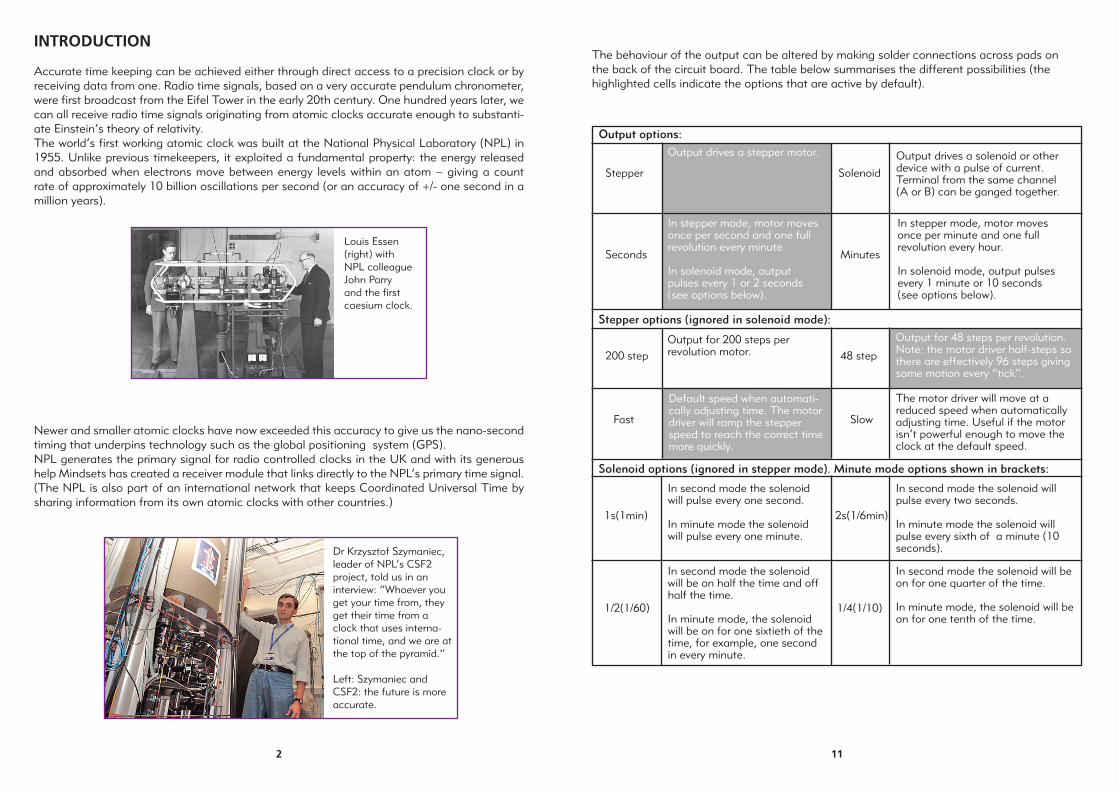
Louis Essen (right) with NPL colleague John Parry and the fi rst caesium clock.
Dr Krzysztof Szymaniec, leader of NPL’s CSF2 project, told us in an interview: “Whoever you get your time from, they get their time from a clock that uses interna-tional time, and we are at the top of the pyramid.”
Left: Szymaniec and CSF2: the future is more accurate.
11
Output options:
Stepper
Output drives a stepper motor.
Solenoid
Output drives a solenoid or other device with a pulse of current. Terminal from the same channel (A or B) can be ganged together.
Seconds
In stepper mode, motor moves once per second and one full revolution every minute.
In solenoid mode, output pulses every 1 or 2 seconds (see options below).
Minutes
In stepper mode, motor moves once per minute and one full revolution every hour.
In solenoid mode, output pulses every 1 minute or 10 seconds (see options below).
Stepper options (ignored in solenoid mode):
200 step Output for 200 steps per revolution motor. 48 step
Output for 48 steps per revolution. Note: the motor driver half-steps so there are effectively 96 steps giving some motion every “tick”.
Fast
Default speed when automati-cally adjusting time. The motor driver will ramp the stepper speed to reach the correct time more quickly.
Slow
The motor driver will move at a reduced speed when automatically adjusting time. Useful if the motor isn’t powerful enough to move the clock at the default speed.
Solenoid options (ignored in stepper mode). Minute mode options shown in brackets:
1s(1min)
In second mode the solenoid will pulse every one second.
In minute mode the solenoid will pulse every one minute.
2s(1/6min)
In second mode the solenoid will pulse every two seconds.
In minute mode the solenoid will pulse every sixth of a minute (10 seconds).
1/2(1/60)
In second mode the solenoid will be on half the time and off half the time.
In minute mode, the solenoid will be on for one sixtieth of the time, for example, one second in every minute.
1/4(1/10)
In second mode the solenoid will be on for one quarter of the time.
In minute mode, the solenoid will be on for one tenth of the time.
The behaviour of the output can be altered by making solder connections across pads on the back of the circuit board. The table below summarises the different possibilities (the highlighted cells indicate the options that are active by default).

10
OPTIONS
By default, the pads for the stepper type are bridged to control the 48-step motor provided.If a 200 step motor is to be used then the bridge should be removed (de-soldered) using a soldering iron.
3
THE ATOMIC CLOCK MODULE (RECEIVER)
The atomic clock receiver picks up the time signal from the NPL using a ferrite rod aerial similar to one in an older transistor radio. It also contains its own very accurate crystal-controlled clock to maintain continuity if, for example, the NPL signal is lost for a short time. The receiver drives a stepper motor one revolution per minute – whose spindle can then drive a gear train to indicate minutes, hours etc. You can download the fi les for cutting these geared wheels from www.mindsetsonline.co.uk. It is important to remember that a fi nished clock - like the fantastic skeleton clocks of the nineteenth century - can take many different forms. The example shown is a second laser-cut version of the clock keeping atomic time at East Barnet School in North London.
The clock also offers many other options such as pulsing a solenoid rather than driving a motor, providing an auto re-set function, working with a different type of aerial etc. All these are described on the following pages.

4
GETTING STARTED
1. Connect the aerial/Antenna (Ferrite rod)
There may be two coils on the ferrite rod provided. If so, use the coil which has the greatest number of turns (the fatter, less-tidy looking coil), you can slide off the unused coil and discard it. The remaining coil has 4 wires (there are actually two coils on the bobbin), connect the black and pink wires to the screw terminals marked ANT.
Alternatively, any ferrite rod designed for use in a LW radio can be adapted. If there are four wires present, use a multimeter to fi nd the pair of wires that has the highest resistance (this is the longer coil).
Usually, in a LW/MW radio receiver the ferrite rod forms a tuned circuit with a capacitor to select the desired frequency. The TEP Atomic Clock receiver works in a different way. The incoming signal is fi rst digitised, then mathematically analysed to pick out the MSF signal at 60 kHz. The antenna is loaded so it can pick up a wide range of frequencies, hence, the tuning of the antenna is not critical.
The ferrite rod antenna has a null along its axis. This means if the rod is pointing straight at the transmitter, no signal will be received. The MSF transmitter is located at Anthorn, Cumbria, in the North West of England. If you are in the South of England you should have the ferrite rod aligned roughly East-West. If you are in Newcastle, for example, the ferrite rod should be aligned North-South.
Power
Ferrite Rod (Aerial)
12 o’ clock switch(optional)
Solenoid / Stepper motor(Red, Yellow, Orange, Black)
9
In our simplifi ed example, the stepper motor is fi rst fi xed to the base and the pinion fi tted. The hour wheel is then held against the motor pinion and its axle position marked through the centre hole. A 2.9mm interference fi t hole is drilled in the base at this point and the stub axle fi tted. The wheel is slipped onto this axle and supported at the correct distance from the base with a cut length of tubing or washers.
The wheel must mesh freely with the motor pinion gear. If it is tight, simply drill another axle hole (at a slightly increased distance) above or below the original.When you are satisfi ed with the position, slip over the second pinion gear and glue in place. This procedure is repeated for the next and any subsequent wheels.
The designs for a set of acrylic gears is available from Mindsets that can be downloaded from our website free of charge if you have a laser cutter. These fi les can be scaled to give teeth of any size.

8
SETTING OUT A GEAR TRAIN
Adding a train of gears to the stepper motor is the really creative aspect of the clock’s design since an infi nite number of interpretations are possible – including, for example, additional wheels to denote longer period of time or notable events. Because of the compound nature of the gearing, adding just a few more wheels can easily provide - in principle at least - a thousand year indicator !
In the example shown, a 6 tooth pinion gear, laser cut from acrylic, has been tightly fi tted to the stepper spindle. This drives a 360 tooth wheel to give a 60:1 reduction – indicating one hour per revolution. A second 8 tooth pinion gear fi tted to the hour wheel then drives a 192 tooth wheel to give a 24 hour display.
The gears rotate on 3mm diameter roller pin stub axles (stock no. 131-022A) which are force fi tted into a base board of any material – e.g., acrylic or MDF. Small lengths of tubing or washers can be used for both spacing and as retaining bushes. The smaller pinions can be fi xed at the centres of the larger gears with a super glue or equivalent.
It is important that the gears mesh or ‘depth’ to turn without jamming together. In clock making a depthing tool – a type of beam compass - is used to mark out the positions for the gearwheel centres.
5
2. Connect the Output
Bipolar Stepper Motor (included)
Any small, bipolar, 48 steps/revolution stepper motor is ideal, as by default, this is what the receiver is set to control. 200 step motors can also be used (see the Options section).A bipolar stepper motor will have four leads (the plug can be cut off and disposed of): two pairs each connected to an internal coil. Each of the two coils should be connected to a channel of the output (A or B; in the sequence shown on page 4). If you fi nd the stepper motor moves backwards, swap which coil is connected to A and B over. You can use a multimeter to fi nd which wires are from the same coil (there will be continuity between them).
Unipolar Stepper Motor
A 6-lead unipolar motor can be used by connecting the centre taps to the + power terminal or by ignoring the centre taps and using the motor as a bipolar stepper. If your motor has fi ve leads, it must be used as a unipolar motor. You may need to experiment with the order of connections if you don’t have information for your stepper motor.
Hybrid Stepper Motor
If you have a stepper motor with eight leads (a hybrid stepper motor), you should be able to confi gure it as a bipolar motor with series or parallel windings (choose the best for your power supply). If you don’t have information for you motor, you can fi nd the leads for the four inter-nal coils by testing for continuity with a multimeter. To confi gure the motor as bipolar series, connect pairs of coils in series, then treat the series coils as one coil and connect to channel A and B. You may need to swap which coils are connected in series if the motor doesn’t step properly.
Solenoid
The receiver can be confi gured to pulse a solenoid at regular intervals (see the Options section). To connect a solenoid, wire one lead to both channel A terminals, and the other lead to both channel B terminals. By connecting the channel A terminals together and the channel B terminals together, the maximum current can be delivered to the solenoid (about 2A).

6
3. Connect the 12 O’Clock Switch - If required
The 12:00 input provides a method for the physical clock and the receiver to stay in sync. When a switch connected to the 12:00 input is closed, the receiver interprets this as the clock being physically in the 12 o’clock position. If there is a discrepancy (i.e. it is not 12 o’clock), the clock hands will rapidly move to the show the correct time (if a stepper motor is being used). The table below shows the different ways of using the input.
12:00 Input Behaviour of Clock
Unconnected If nothing is connected to the 12:00 input, the receiver assumes the hands have been manually adjusted to the correct time. The receiver will adjust the clock to refl ect time changes, for example, daylight savings.
Permanently shorted (before power applied) If the 12:00 input is permanently short- circuited (for example with a piece of wire). The receiver will assume the clock hands read 12 o’clock when power was applied. Once the receiver has locked on to a valid time signal, the clock will rapidly move to show the correct time.
Switch which closes when hands are If the 12:00 input is connected, for example,in 12:00 position to a reed switch that closes when the hands read 12 ‘o’clock. The receiver will adjust the clock hands if there is a discrepancy.
12 o’ clock switch(optional)
7
4. Connect the Power
The circuit can run from 5V to 24V. The voltage is internally reduced for the receiver and decoder circuit, however, the motor driver chip is powered at the full voltage. In other words if you want to use a 12V stepper motor, simply run the board on 12V (this is the only power source needed).The motor driver can handle up to 1A of current per channel (A and B), therefore, it can use 2A in total. Ensure your power source can supply enough current for the stepper motor or solenoid used. The circuit can be powered using batteries or a regulated PSU. Be aware that stepper motors and solenoids can use a lot of current, so batteries may not last.
Once you have a power supply connected you should see the red RX LED fl ashing every second. Sometimes you will see a double fl ash, or the LED will seem to stay on a little longer, this is how the data is encoded on the signal. You may need to slide the coil along the rod to get a better signal. Once the receiver has locked on to the time signal the green LOCK LED will fl ash once every second. It will usually take 2 to 3 minutes to lock on to a valid signal.
Finally, instead of a ferrite rod it is possible to use an antenna formed by winding an 11m length of insulat-ed wire in 16 circular loops. The diameter of the loops should be 19.5cm. Keep the loops tight, for example, with some insulation tape. The pair of wires, from the loop antenna to the ANT terminals also need to be kept together.
Not locking on to time signal/erratic RX LED
The RX LED should fl ash (or double fl ash) once per second. If the RX LED appears erratic, it is mostly likely not receiving a signal and responding to local interference. The following checks might be helpful:It can sometimes be tricky to get a good connection to the thin wire of the coil. You can check this by measuring the resistance between the screw heads on the ANT terminal block (with the coil connected). You should get a reading around 40 ohms. If not, scrape the end of the coil wire with a knife to expose more copper. You can also try tinning the ends with solder.To ensure the correct coil is connected, measure the resistance between the four wires from the ferrite rod. Choose one wire and measure the resistance to the other three wires. You should only get a resis-tance reading from one other wire. These two wires are the ends of one coil. Measure the resistance of the remaining pair. Now connect the pair that had the highest resistance to the ANT terminal block. For example, if one pair of wire gives a reading of 39 ohms and the other pair 3 ohms, use the fi rst pair.Try changing the position of the coil on the ferrite rod and the orientation of the rod.Change location. Some buildings attenuate the time signal and there may also be a source of interfer-ence nearby.The circuit may need several minutes to lock. If the RX LED appears to fl ash once per second, try leaving the board for an hour to see if a lock is obtained. Also, a better signal is often available at night.
Clock ticking backwards
Swap the wires round for one coil of the stepper motor.
Stepper motor ticking but not revolving
This is most likely caused by incorrect connections. Use a multimeter to establish which wires connect to the same coil and reconnect to the circuit.
Troubleshooting