atmospheric neutral density experiment risk reduction ... · atmospheric neutral density experiment...
TRANSCRIPT

Atmospheric Neutral Density Experiment Risk Reduction
(ANDE-RR) Flight Hardware Details
Andrew C. Nicholas, ∗
Ted Finne, †
Mark A. Davis, ‡
January 26, 2007
Overview
The ILRS community has requested particular documentation for all missions that the laser stations supports.The main purpose of this document is to be the repository of the raw measurements supporting this requestfor the ANDERR mission (Figure 1). These encompasses both the technical requirements for the laser basedtracking and the target corrections to full exploit the data accuracy, precision, signature to further the sciencebenefit of the field measurements. Using the example document from Appleby for the GIOVA mission as atemplate the following sections are provided to answer the 16 required questions that were formed in 2006by the missions working group. Additionally, the inclusion and annotation of design, measured, and deriveddata has been attempted, so that collaborative assessment of performance will be possible. Further detailscan be found in the referenced documents, however if information is gathered outside this work, the authorsrequest that it be requested to appear in updates to this document so as to further the template work byexample of information needed to support the full ANDE and other ILRS supported missions.
Summary of LRA information and ILRS MWG questions
QUESTION 1) Array type (spherical, hexagonal, planar,etc.), to include a diagram or photograph.ANSWER 1) Arrays are 19.0 inch and 17.5 inch diameter spherical objects with photos shown in
Figure 2, 4 and 5. Each spacecraft is fitted with a set of thirty 12.7 mm diameteroptical retro reflectors for SLR located along latitudianl bands at + / - 90 deg,+ / - 52.5 deg, and + / - 15 deg with one, six and eight retroreflectors perband respectively.
QUESTION 2) Array manufacturer.ANSWER 2) Array is an US Naval Research Laboratory custom design by the Naval Center for Space
Technology and with Implementation and fabrication by the NRL Space Sciences Division.
QUESTION 3) Link (URL or reference) to any ground-tests that were carried out on the array.ANSWER 3) Ground testing on the array was not performed but the array is very similar that
of Starshine3. Surface measurement details in the references.
∗Naval Research Laboratory, Code 7607, Thermospheric and Ionospheric Research and Applications Group, WashingtonD.C. 20375
†Naval Research Laboratory, Code 7607, Praxis Inc, Alexandria, VA 22303‡Naval Research Laboratory, Code 8123, Electro-Optics Technology Sections, Honeywell Technology Solutions, Inc., Wash-
ington D.C. 20375
1

26-Jan-2007
26-Jan-2007
2
Figure 1: The ANDE Risk Reduction LOGO
QUESTION 4) The LRA design and/or type of cubes was previously used on the following mission:ANSWER 4) The LRA design and type of cubes is similar to that used on the Starshine 1
and 3 Missions. See reference [Kessel], Figure 16 and details following.Analytically derived mean cross section is from 0.1 e6 + / - 0.05 e6 meters^2
QUESTION 5) The 3-D location (possibly time-dependant) of the satellite’s mass centre relative toa satellite-based origin.
ANSWER 5) The 3D location of the center of mass is shown in Tables 1 and 2 and is boundedby 1.1 millimeter
QUESTION 6) The 3-D location of thte phase centre of the LRA relative to a satellite-based origin.ANSWER 6) The optical phase center to satellite origin is 224.7 mm for the MAA (Active) and
205.2 mm for the FCAL (Passive). Relationship to origin will require attitude.
QUESTION 7) The position and orientation of the LRA reference point (LRA mass-centre or marker onLRA assembly) relative to a satellite-based origin.
ANSWER 7) The position of the LRA reference to the satellite origin is not needed for a sphereThe mass properties have been included for long term spin vector determination.

26-Jan-2007
26-Jan-2007
3
QUESTION 8) The position (xyz) of either the vertex or the centre of the front face of eachcorner cube within the LRA assembly, with respect to the LRA reference point andincluding information of amount of recession of the front faces of cubes.
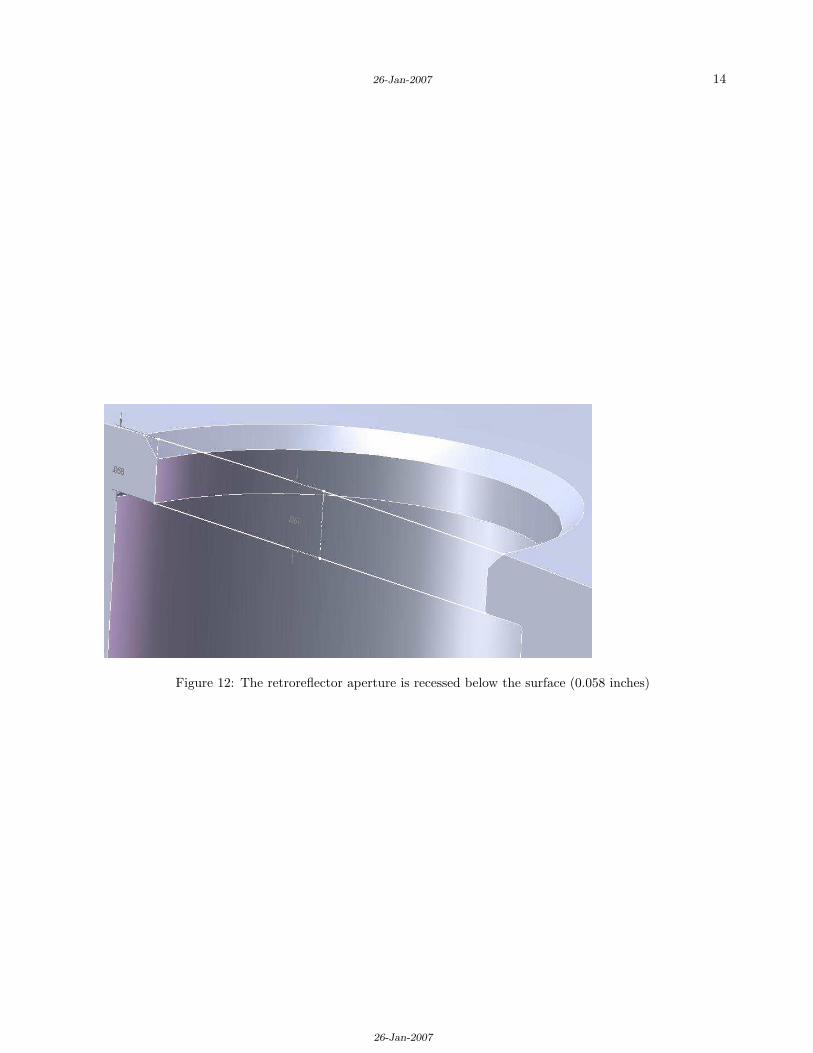
ANSWER 8) The vertex of each reflector is shown in Tables 1 and 2.The recession is shown in Figure 12 and 15. The diameter of the hole exposingthe aperture is 10.67 millimeters centered about the vertex aperture axis.
QUESTION 9) The orientation of each cube within the LRA assembly (three angles for each cube).ANSWER 9) The orientation for each cube is radially outward. These are constructed so that
the aperture is normal to the tangent of the sphere at each location. Thetolerance is XXXX degrees.
QUESTION 10) The shape and size of each corner cube, especially the height.ANSWER 10) The size and shape of each corner cube is shown in Figure 6 is Edmund NT45-202.
The height of these 10.2 mm COTS retro reflectors is measured to be 10.16 mmwith + or - 0.25 mm uncertainty.
QUESTION 11) The material from which the cubes are manufactured (e.g. quaratz);ANSWER 11) The Material for each corner cube is BK7.
QUESTION 12) The refractive index of the cube material, at a range of wavelengths.ANSWER 12) The refractive index of the cube material BK7 is 1.53815 for 355 nm, 1.52805
for 423.5 nm 1.51947 for 532 nm, 1.50991 for 847 nm, 1.50663 for 1064 nm,1.50059 for 1555 nm. For reference the commonly used fused silica index
variation would be 1.47607, 1.46782, 1.46071, 1.45256, 1.44963 and 1.44396respectively.
QUESTION 13) Dihedral angle offset(s) and the manufacturing tolerance.ANSWER 13) The Dihedral angle offsets are zero with a manufacture tolerance such that the
beam deviation is less than + or - 3 arc seconds. These were not confirmed byindependent quality control process beyond industry practice at Edmund.
QUESTION 14) Radius of curvature of the front surfaces of cubes if applicable.ANSWER 14) The radius of curvature of the aperture of the cubes is infinity. There is no
intended power from the aperture on these retroreflecotrs.
QUESTION 15) Flatness of cubes surfaces (as a fraction of wavelenth);ANSWER 15) The flatness of the cubes surfaces (as a function of 633 nm light) is such that
after the three back faces and two aperture crossings the beam remains lambda / 8.
QUESTION 16) Whether or not the cubes are coated and with what material.ANSWER 16) The aperture of the cubes are coated with the Edmund Custom V2 (532 and 1064) Anti
reflection coating. The back faces have vacuum deposited silver.
26-Jan-2007
26-Jan-2007
4
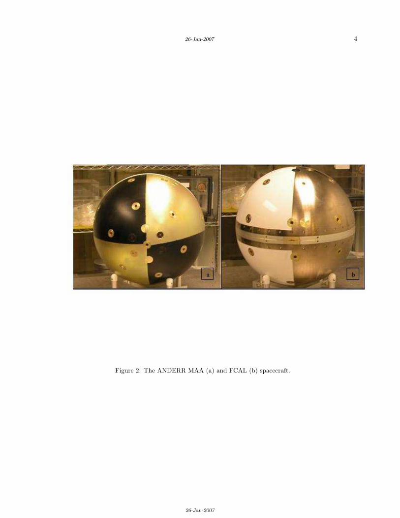
Figure 2: The ANDERR MAA (a) and FCAL (b) spacecraft.
26-Jan-2007
26-Jan-2007
5
Flight Hardware Overview of the ANDERR (Questions 1,2,3)
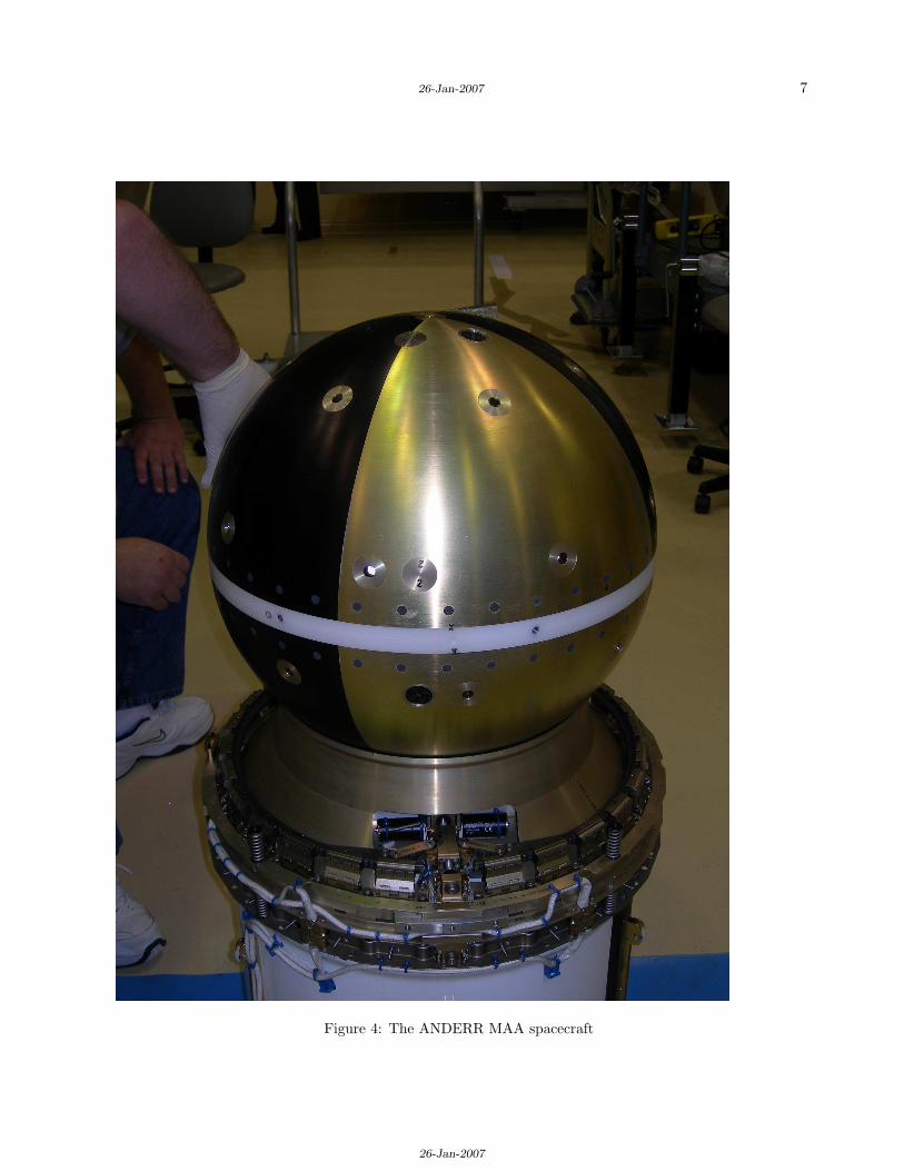
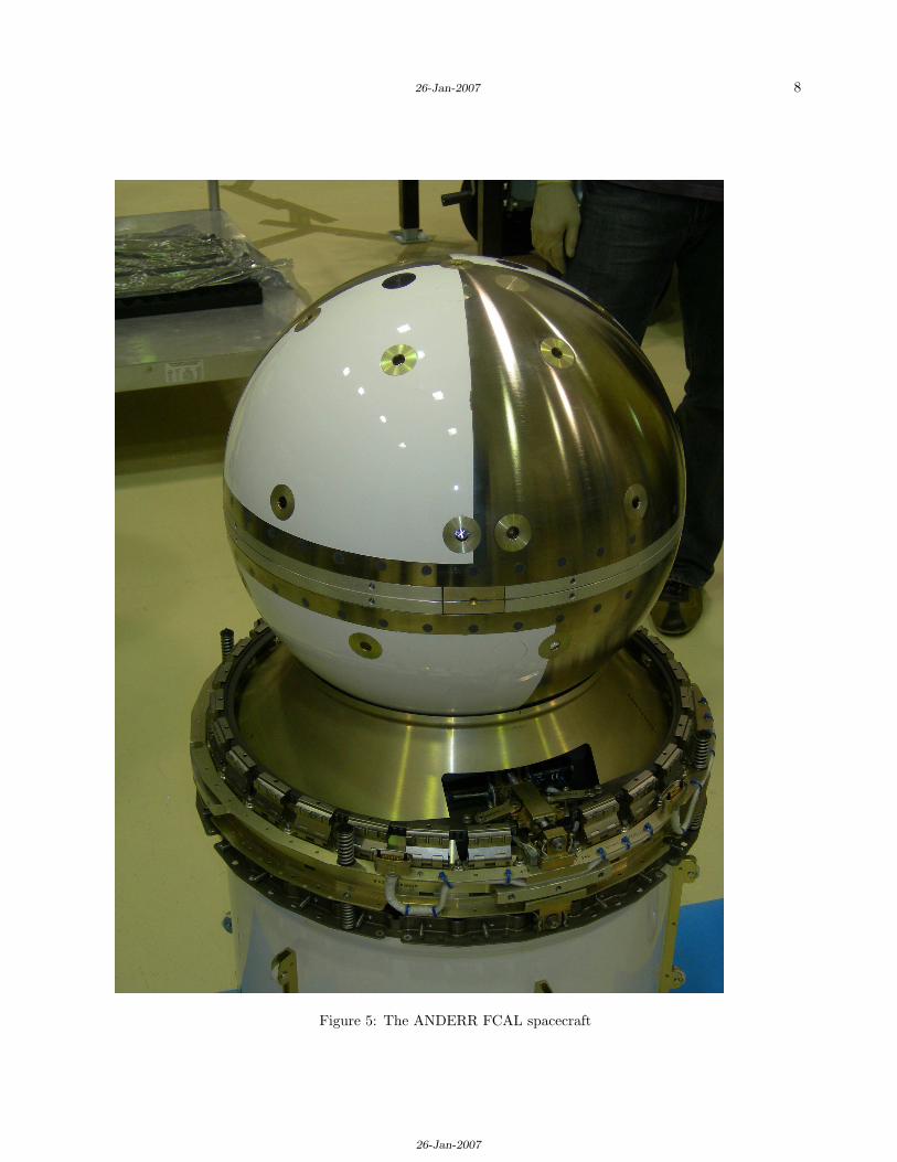
There were a total of 5 components deployed as an Internal Cargo Unit (ICU) from the NASA STS-116Discovery Flight shown in Figure 3. This deployment object will not be spinning about the long axis ofthe cylinder (ICU) and is separated from the Cargo Bay with delta-V in the range 0.45 to 0.61 meters persecond. The ICU system of 5 components will separate approximately 40 seconds later into componentsCylinder1, MAA, Disk1, FCAL, Cylinder2, under spring forces using a light band deployment systems asshown in Figure 3. Only the spherical objects MAA (Figure 4) and FCAL (Figure 5) have retro reflectorsin a spherical configuration of these five objects. These were manufactured and assembled at NRL using avariety of custom and cots components. The surface finish on the MAA is aluminum with black anodizedand gold irridited. The surface finish on the FCAL is white paint and nickel coated brass. Under a nominaldeployment the MAA will be spinning a 5 revolutions per minute and the FCAL will be negligible, howeverthe deployment resulted in a negligable spin to both spacecraft.. Confirmation using ground techniques willbe desired days after deployment. There will be high definition video for the first few minutes for accuratecomparison. The spin is required on the follow-on ANDE flight for the accurate sensing of the speciesconstituents and the thermal control for the modulators and other hardware. The ILRS nomenclature forthe MAA and FCAL will be ANDERRA (Active) and ANDERRP (Passive) for the CPF prediction names.While both have active RF transmitters sending measurements to the ground, this naming convention isconsistent with the laser diode sources on the MAA. The MAA sphere has COSPAR 0605506, catalog 29664,and SIC 1071. The FCAL sphere has COSPAR 0605510, catalog 29667, and SIC 1072.

26-Jan-2007
26-Jan-2007
6
Figure 3: The ANDERR deployer from the Space Shuttle
26-Jan-2007
26-Jan-2007
7
Figure 4: The ANDERR MAA spacecraft
26-Jan-2007
26-Jan-2007
8
Figure 5: The ANDERR FCAL spacecraft
26-Jan-2007
26-Jan-2007
9
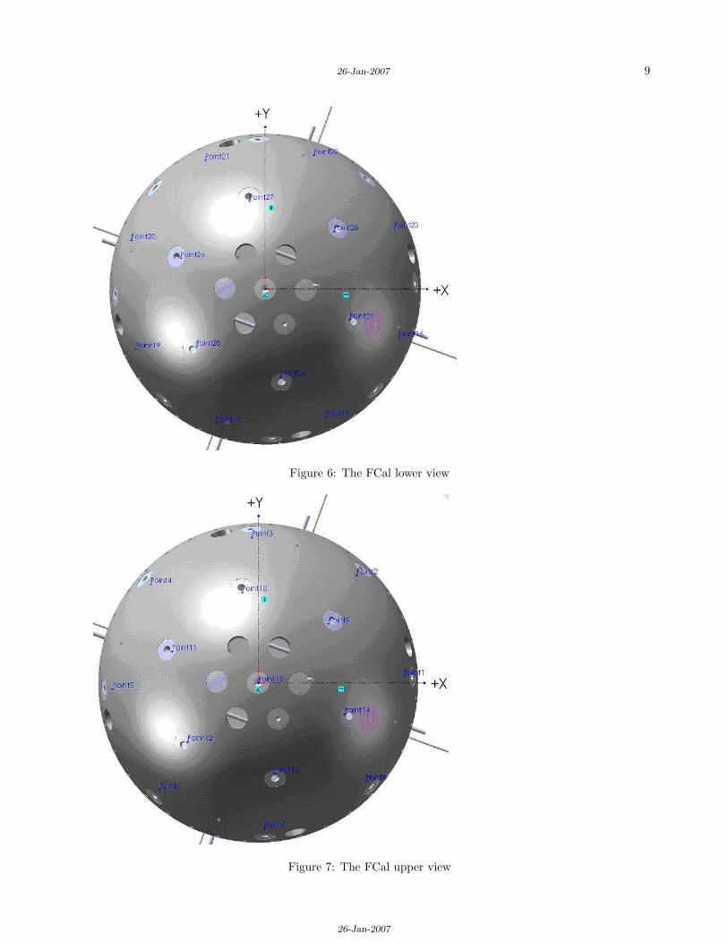
Figure 6: The FCal lower view
Figure 7: The FCal upper view

26-Jan-2007
26-Jan-2007
10
Figure 8: The MAA lower view
Figure 9: The MAA upper view

26-Jan-2007
26-Jan-2007
11
Retro Reflectors and corrections the ANDERR MAA (Active) andFCAL (Passive) (Questions 4 through 16)
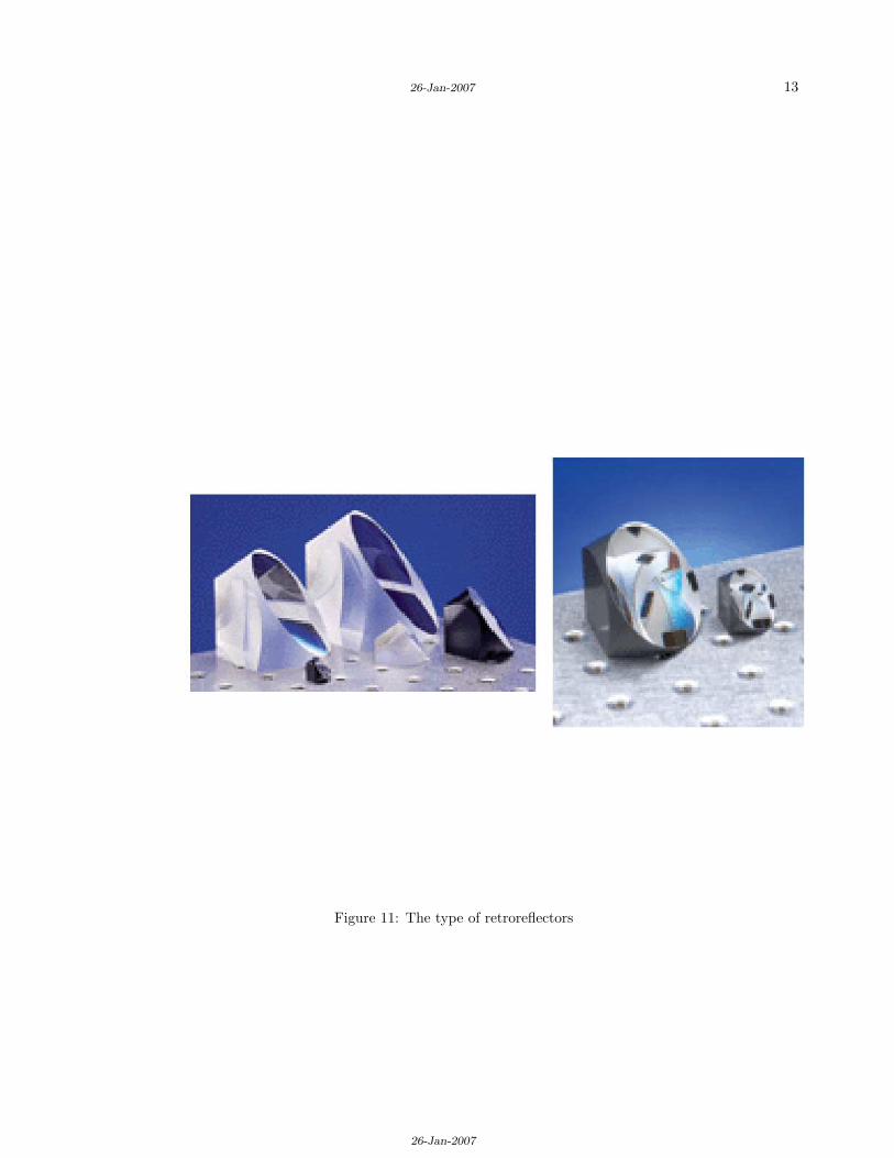
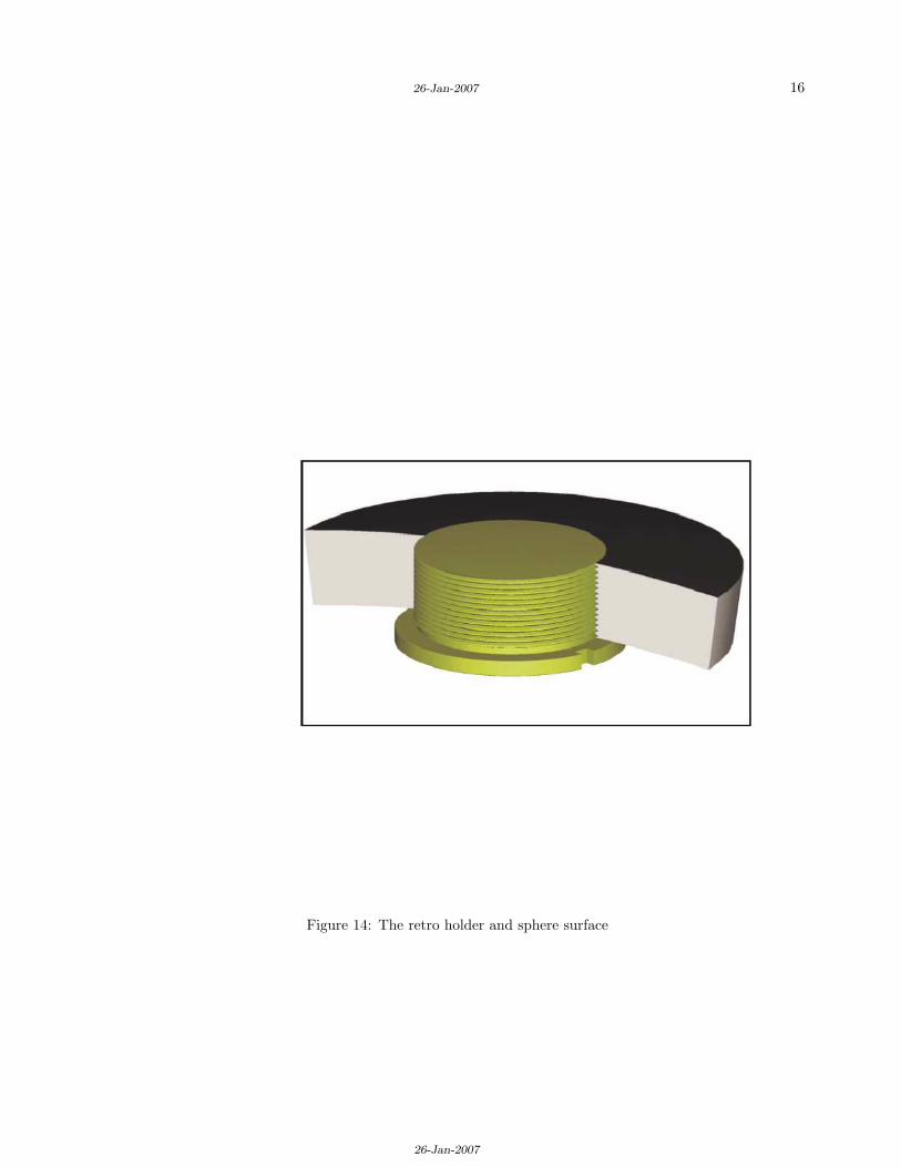
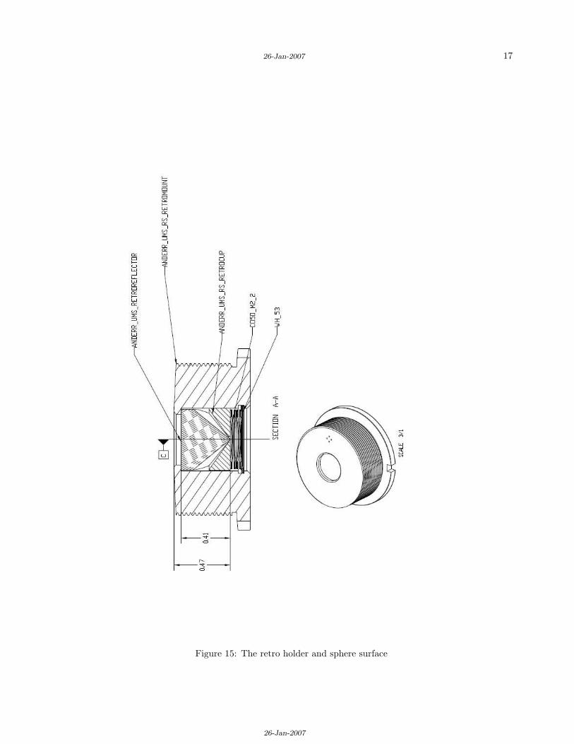
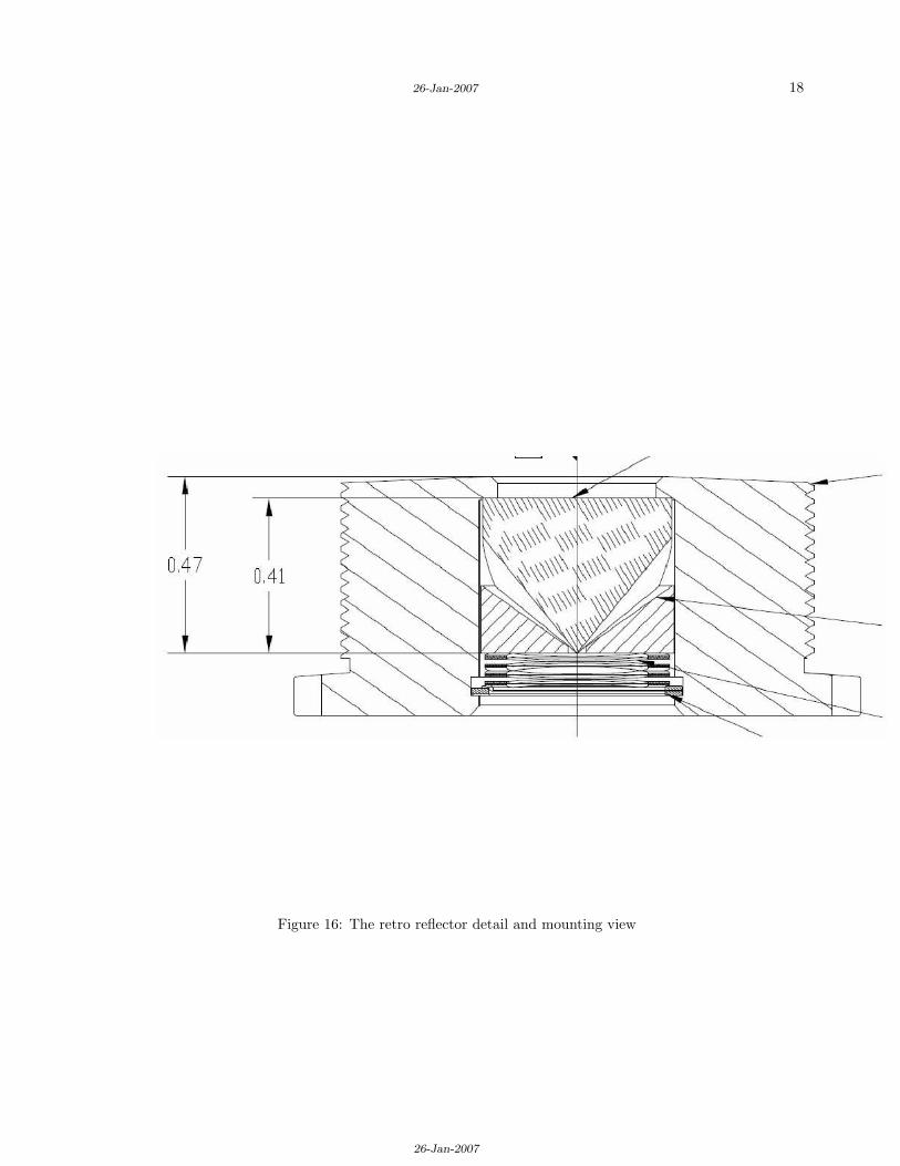
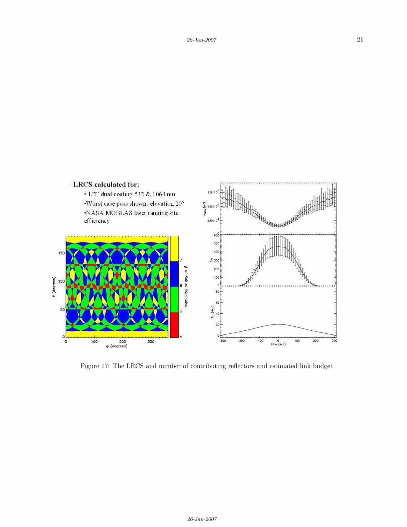
There are thirty retro reflectors on each sphere in an orientation of + / - 90, 52.5 and 15 degrees fromthe equator, with one, six and eight retroreflectors per band respectively. The retro reflectors are EdmundOptics NT45-202 12.7 mm prism corner cubes as shown in Figure 11. These have aperture to vertex (height)distances for 10.16 mm as shown in Figure 10. The exposed aperture is 0.42 inches (10.67 mm) diameters asshown in Figure 13. After mounting in the universal holder shown in Figure 14, the optical testing did notinclude metric performance testing. These holders then threaded from the inside of the sphere. The apertureof each reflector is (0.058 inches) 1.52 mm below the holder lip as shown in Figure 12, which has negligibleimpact on the theoretical incidence angle functionality and cross section. Details of the mounting are shownin expanded view Figures 16 and 15. The retroreflector spatial design (number and orientation) is a reuse ofthat used on the Starshine flights and consists of 30 reflectors on a sphere providing overlap and cross sectionshown in Figure 17. Estimates of the 532nm optical cross section of this design exceed 0.05 Million squaremeters in the worst orientation with more typical values near 0.12. The use of the COTS retro reflectors hasbeen used successfully by NRL on other very LEO missions and the tolerancing and non-rad-hard substratesare a research area but not expected to degrade over the short lifespan of these satellites.
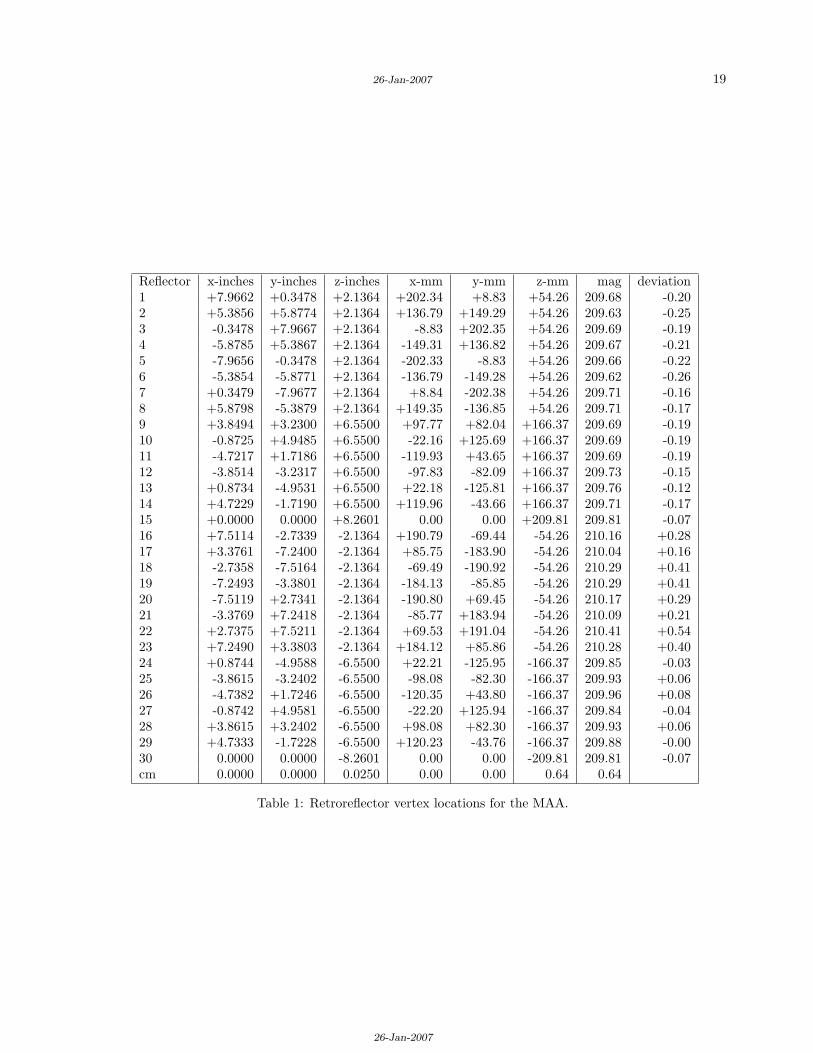
The aperture coatings on each reflector is the 2V (532 and 1064 nm) COTS antireflective product fromEdmunds. The back faces are vacuum deposited silver with inconel and black over paint. The orientation ofeach reflector is radially outward, with vertex of each reflector located at positions shown in Tables 1 and 2.The number of significant digits in the inches columns is directly from the 3-d modeling software. The metricand computed radius and dispersion are numerically derived from the inches measurements. The as-builthardware generally agrees with the design model to + / - 0.015 inches or + / - 0.38 mm. These have meanvalues of 229.41 (stdev 0.64) and 209.88 ( stdev 0.23) mm for MAA and FCAL respectively. Given that theaperture to vertex distance is 10.16 and index of the BK7 material at 532 nm being 1.51947, the opticalphase center will be 5.28 mm inside the sphere of vertex locations. The center of mass correction for theMAA (ACTIVE) is 224.1 mm and for FCAL (PASSIVE) is 204.6 mm. It should be noted that the center ofmass of each object is slightly offset from the frame used for measuring the vertex locations by at most 1.1millimeter and that spin rate and orientation would need to be modeled for any improvements. Some of thisorientation data will be in the experimental data that is downlinked and available from the web link [10].
The aperture of each retroreflector has a small recession below the satellite surface as shown in Figure12. This has been measured to be less than 1.55 mm at the center of the aperture. Due to the curvatureover the size of the aperture this is 0.061 in the center and 0.058 inches. This was chosen to minimize theoverall surface deviations and retain the average curvature of the outer sphere diameter.
Most of the design was done using English units with mechanical tolerancing being + / - 15 mils. Themetric equivalent (0.38 mm) have been included for the reader and were in most all cases derived.

26-Jan-2007
26-Jan-2007
12
Figure 10: The retro reflectors vendor basic components
26-Jan-2007
26-Jan-2007
13
Figure 11: The type of retroreflectors
26-Jan-2007
26-Jan-2007
14
Figure 12: The retroreflector aperture is recessed below the surface (0.058 inches)

26-Jan-2007
26-Jan-2007
15
Figure 13: The retro reflector detail mounting with diameter of exposure
26-Jan-2007
26-Jan-2007
16
Figure 14: The retro holder and sphere surface
26-Jan-2007
26-Jan-2007
17
Figure 15: The retro holder and sphere surface
26-Jan-2007
26-Jan-2007
18
Figure 16: The retro reflector detail and mounting view
26-Jan-2007
26-Jan-2007
19
Reflector x-inches y-inches z-inches x-mm y-mm z-mm mag deviation1 +7.9662 +0.3478 +2.1364 +202.34 +8.83 +54.26 209.68 -0.202 +5.3856 +5.8774 +2.1364 +136.79 +149.29 +54.26 209.63 -0.253 -0.3478 +7.9667 +2.1364 -8.83 +202.35 +54.26 209.69 -0.194 -5.8785 +5.3867 +2.1364 -149.31 +136.82 +54.26 209.67 -0.215 -7.9656 -0.3478 +2.1364 -202.33 -8.83 +54.26 209.66 -0.226 -5.3854 -5.8771 +2.1364 -136.79 -149.28 +54.26 209.62 -0.267 +0.3479 -7.9677 +2.1364 +8.84 -202.38 +54.26 209.71 -0.168 +5.8798 -5.3879 +2.1364 +149.35 -136.85 +54.26 209.71 -0.179 +3.8494 +3.2300 +6.5500 +97.77 +82.04 +166.37 209.69 -0.1910 -0.8725 +4.9485 +6.5500 -22.16 +125.69 +166.37 209.69 -0.1911 -4.7217 +1.7186 +6.5500 -119.93 +43.65 +166.37 209.69 -0.1912 -3.8514 -3.2317 +6.5500 -97.83 -82.09 +166.37 209.73 -0.1513 +0.8734 -4.9531 +6.5500 +22.18 -125.81 +166.37 209.76 -0.1214 +4.7229 -1.7190 +6.5500 +119.96 -43.66 +166.37 209.71 -0.1715 +0.0000 0.0000 +8.2601 0.00 0.00 +209.81 209.81 -0.0716 +7.5114 -2.7339 -2.1364 +190.79 -69.44 -54.26 210.16 +0.2817 +3.3761 -7.2400 -2.1364 +85.75 -183.90 -54.26 210.04 +0.1618 -2.7358 -7.5164 -2.1364 -69.49 -190.92 -54.26 210.29 +0.4119 -7.2493 -3.3801 -2.1364 -184.13 -85.85 -54.26 210.29 +0.4120 -7.5119 +2.7341 -2.1364 -190.80 +69.45 -54.26 210.17 +0.2921 -3.3769 +7.2418 -2.1364 -85.77 +183.94 -54.26 210.09 +0.2122 +2.7375 +7.5211 -2.1364 +69.53 +191.04 -54.26 210.41 +0.5423 +7.2490 +3.3803 -2.1364 +184.12 +85.86 -54.26 210.28 +0.4024 +0.8744 -4.9588 -6.5500 +22.21 -125.95 -166.37 209.85 -0.0325 -3.8615 -3.2402 -6.5500 -98.08 -82.30 -166.37 209.93 +0.0626 -4.7382 +1.7246 -6.5500 -120.35 +43.80 -166.37 209.96 +0.0827 -0.8742 +4.9581 -6.5500 -22.20 +125.94 -166.37 209.84 -0.0428 +3.8615 +3.2402 -6.5500 +98.08 +82.30 -166.37 209.93 +0.0629 +4.7333 -1.7228 -6.5500 +120.23 -43.76 -166.37 209.88 -0.0030 0.0000 0.0000 -8.2601 0.00 0.00 -209.81 209.81 -0.07cm 0.0000 0.0000 0.0250 0.00 0.00 0.64 0.64
Table 1: Retroreflector vertex locations for the MAA.

26-Jan-2007
26-Jan-2007
20
Reflector x-inches y-inches z-inches x-mm y-mm z-mm mag deviation1 +8.6577 +1.1741 +2.3484 +219.91 +29.82 +59.65 229.80 +0.392 +5.3187 +6.9573 +2.3484 +135.09 +176.72 +59.65 230.30 +0.893 -1.1316 +8.6857 +2.3484 -28.74 +220.62 +59.65 230.34 +0.934 -6.9148 +5.3467 +2.3484 -175.64 +135.81 +59.65 229.89 +0.485 -8.6432 -1.1036 +2.3484 -219.54 -28.03 +59.65 229.22 -0.196 -5.3042 -6.8868 +2.3484 -134.73 -174.92 +59.65 228.71 -0.707 +1.1461 -8.6152 +2.3484 +29.11 -218.83 +59.65 228.67 -0.738 +6.9293 -5.2762 +2.3484 +176.00 -134.02 +59.65 229.12 -0.299 +3.8956 +3.9236 +7.1768 +98.95 +99.66 +182.29 230.11 +0.7110 -1.4169 +5.3501 +7.1768 -35.99 +135.89 +182.29 230.20 +0.7911 -5.3054 +1.4588 +7.1768 -134.76 +37.05 +182.29 229.70 +0.2912 -3.8808 -3.8528 +7.1768 -98.57 -97.86 +182.29 229.18 -0.2313 +1.4306 -5.2768 +7.1768 +36.34 -134.03 +182.29 229.16 -0.2514 +5.3191 -1.3881 +7.1768 +135.11 -35.26 +182.29 229.62 +0.2215 0.0000 0.0000 +9.0434 0.00 0.00 +229.70 229.70 +0.3016 +8.4128 -2.2170 -2.3484 +213.69 -56.31 -59.65 228.89 -0.5217 +4.3551 -7.4954 -2.3484 +110.62 -190.38 -59.65 228.12 -1.2818 -2.2440 -8.3665 -2.3484 -57.00 -212.51 -59.65 227.96 -1.4419 -7.5234 -4.3126 -2.3484 -191.09 -109.54 -59.65 228.20 -1.2120 -8.3992 +2.2878 -2.3484 -213.34 +58.11 -59.65 229.02 -0.3921 -4.3406 +7.5659 -2.3484 -110.25 +192.17 -59.65 229.44 +0.0422 +2.2595 +8.4408 -2.3484 +57.39 +214.40 -59.65 229.82 +0.4223 +7.5379 +4.3831 -2.3484 +191.46 +111.33 -59.65 229.37 -0.0424 +5.3209 -1.3885 -7.1768 +135.15 -35.27 -182.29 229.65 +0.2525 +1.4305 -5.2762 -7.1768 +36.33 -134.02 -182.29 229.15 -0.2526 -3.8810 -3.8530 -7.1768 -98.58 -97.87 -182.29 229.18 -0.2227 -5.3042 +1.4585 -7.1768 -134.73 +37.05 -182.29 229.68 +0.2828 -1.4160 +5.3467 -7.1768 -35.97 +135.81 -182.29 230.15 +0.7429 +3.8955 +3.9235 -7.1768 +98.95 +99.66 -182.29 230.11 +0.7130 0.0000 0.0000 -9.0434 0.00 0.00 -229.70 229.70 +0.30cm -0.0250 -0.0250 0.0250 -0.64 -0.64 0.64 1.10
Table 2: Retroreflector vertex locations for the FCAL.
26-Jan-2007
26-Jan-2007
21
Figure 17: The LRCS and number of contributing reflectors and estimated link budget

26-Jan-2007
26-Jan-2007
22
Solar Reflection Details
The paint scheme of 8 quadrants of two varieties permits the measurement of solar flux variability. The plotsin Figure 20 and 21 show the expected reflectance ratios for observing with the non-ranging bands on someof the SLR observatories. Details of these measurements were made and described in Abercrombie [4].
Radio and Optical Transmissions and Thermal Details
The US Naval Academy has designed and built the 2 Watt ERP downlink system for the MAA spacecraftwhich will transmit payload data at 145.825 MHz at nominally 2 minute intervals. This signal will have 20MHz bandwidth. Much of the detail is described on the web site [9] and [8].
There are experiments planned for MAA which require known optical flux and as such there are laserdiodes which will emit thru the universal mounting ports adjacent to the retro reflectors. These are operatednominally over Hawaii and will degrade the battery life (and hence the RF transmissions of payload data)late in the mission if used often over other areas. There are 6 output ports for the 810 nm laser firing atdifferent rates each at 100 msec duration as shown in Figure 18. This system is actived by RF uplink andwill function for 300 seconds. Proposals and details for activation on other geographic are being consideredfor research purposes.
The FCal transmitter operates at 436.81 MHz. The transmitter is an FM transmitter consisting of anexiter and power amplifier. The exciter is crystal controlled adn has a modulation input port for an audiosignal or AFSK signal. The output level of the exciter is 10 mW. The exciter output is connected to theamplifier circuit. The amplifier is a singal IC device capable of a maximum of 800 milliwatts output. Theoutput level is adjustable and has been set to 250 milliwats. The output of the amplifier is single endedwith a low pass filter. It is routed to splitters with a 180 degree phase shift between the two outputs. Theoutputs are routed vias coaxial cable to two antenna boards on opposite sides of the FCAL.
The web site [10] has the most current realtime telemetry packets decoded. There are numerious plotsavailable for the sensors at the web links [7]. Additionally the site [11] has details on the decomming ofobservations.
Mass Properties
The outer shell diameter for the MAA and FCAL are 19 inches and 17.5 inches respectively. The mass ofthe MAA is 114.73 lpb or 52.04 kg. The mass of the FCAL is 138.23 lbs or 62.70 kg. The MAA CG inthe satellite xyz frame is at (0.025, 0.025, 0.025) inches. This is (-0.025, -0.025, 0.025) from the geometriccenter. The FCAL CG is at (0.000, 0.000, 0.025) inches.
The diagonal elements (off axis terms are zero) of the MAA Mass moment of Inertia are 14146.72,14146.74, 14340.11 inlbm-in2̂. The equivlanent for the FCAL are 15598.61, 15598.61, 15968.71 lbm-in2̂.
Acknowledgment
The success of the results depend upon the observations and products of all the ILRS stations and coordi-nators. The support of all the contributions is gratefully acknowledged.
References
[1] Andrew C. Nicholas, et. al, “The Atmospheric Neutral Density Experiment (ANDE)”, Proceedings ofthe 2002 AMOS Technical Conference, Maui HI, Sept 2002.
[2] Andrew C. Nicholas, S. Tonnard, I Galysh, P. Kalmanson, B. Bruninga, S. Ritterhouse, J. Englehardt,K. Doherty, J. McGuire, D. Niemi, H. Heidt, M. Hallada, “ANDE Risk Reduction Flight ObservingOpportunities and Mission Update”, Proceedings of the 2005 AMOS Technical Conference, Maui, HI,Sept 2005.

26-Jan-2007
26-Jan-2007
23
Board A1.75 Hz2.75 Hz3.77 Hz
Laser diode output is 500 mW, in 100 msecpulses, at 810 nmPulse repetition varies between 1.5 and 4.25 HzBeam from each of 6 diodes is transmitted through 45 cm, 50 micron core fiber to 6 output apertures, formed by cleaved fibers
Board B1.51 Hz2.26 Hz4.27 Hz
Figure 18: The ACTIVE sphere laser diodes and parameters

26-Jan-2007
26-Jan-2007
24
Figure 19: The ACTVIE sphere (MAA) details with both retroreflectors and laser output ports
[3] Andy Nicholas, “Atmospheric Neutral Density Experiment (ANDE) Risk Reduction Mission”, Posterat the ILRS 15th Workshop, Canberra Australia, Oct 2006.
[4] Kira Abercromby, “Comparisons of Ground Truth and Remote Spectral Measurements of the FOR-MOSAT and ANDE Spacecraft”, Proceedings of the 2006 AMOS Technical Conference, Maui HI, Sept2006, pages 728 to 737.
[5] Robert Kessel, William Braun, Mark Davis, Amey Peltzer, Anne Reed, Ilene Sokolsky, John Vasquez,Paul Wright, “Development and on-orbit performance of moderate-cost spherical retroreflector arraysfor the Starshine program”, 13th ILRS workshop Proceedings, Washington D.C.
[6] Andrew Nicholas, G. C. Gilbreath, S. Thonnard, R. Kessel, R. Lucke, and C. P. Sillman, “The At-mospheric Neutral Density Experiment (ANDE) and Modulating Retroreflector In Space (MODRAS):Combined Flight Experiments for the Space Test Program”, Proceedings of the SPIE Remote SensingConference, Agia Peligia, Crete, Greece, September 23-27 2002, Volume 4884, p49-58.
[7] http://web.usna.navy.mil/b̃runinga/ande-raft-ops.html
[8] http://web.usna.navy.mil/b̃runinga/fcal.html
[9] http://web.usna.navy.mil/b̃runinga/ande.html
[10] http://www.g4dpz.me.uk/ANDE/home.do
[11] http://www.ne.jp/asahi/hamradio/je9pel/anderaft.html

26-Jan-2007
26-Jan-2007
25
Figure 20: The spectral response of the MAA from Reference [4]

26-Jan-2007
26-Jan-2007
26
Figure 21: The spectral response of the FCAL from Reference [4]