atm over xdsl
DESCRIPTION
DSL and ATM technologiesTRANSCRIPT

Chapter 10
ATM over xDSL
Introduction ................................................................................................. 10-3Digital Subscriber Line Technologies ............................................................. 10-3ADSL ........................................................................................................... 10-6SHDSL ......................................................................................................... 10-8
Embedded Operations Channel ........................................................... 10-10ATM .......................................................................................................... 10-11
ATM Call Admission Control (CAC) ..................................................... 10-13Typical settings for ATM over ADSL and SHDSL .................................... 10-15
Data Layers above ATM ............................................................................. 10-16Connection Types Used over ATM ........................................................ 10-16RFC 1483 Multiprotocol Encapsulation ................................................ 10-17
Support on the Router ............................................................................... 10-19Configuration Procedures and Examples .................................................... 10-20
Configure PPPoE over ATM .................................................................. 10-21Configure PPP over ATM (PPPoA) ......................................................... 10-24Configure IP over ATM (IPoA) .............................................................. 10-27Configure ATM RFC 1483 Routed ....................................................... 10-29After configuring ATM ........................................................................ 10-30
Command Reference ................................................................................. 10-31activate atm channel oamfunction ....................................................... 10-31activate shdsl eoccmd .......................................................................... 10-32add atm channel ................................................................................. 10-34create atm ........................................................................................... 10-36deactivate shdsl eoccmd ...................................................................... 10-37delete atm channel .............................................................................. 10-38destroy atm ......................................................................................... 10-38disable adsl ......................................................................................... 10-39disable adsl debug ............................................................................... 10-39disable atm cac ................................................................................... 10-40disable atm channel ............................................................................ 10-40disable shdsl ........................................................................................ 10-41disable shdsl bert ................................................................................. 10-41disable shdsl debug ............................................................................. 10-42enable adsl .......................................................................................... 10-42enable adsl debug ............................................................................... 10-43enable atm cac .................................................................................... 10-43enable atm channel ............................................................................. 10-44enable shdsl ........................................................................................ 10-44enable shdsl bert ................................................................................. 10-45enable shdsl debug ............................................................................. 10-46reset adsl ............................................................................................. 10-48

10-2 AlliedWare OS Software Reference
reset adsl counter ................................................................................ 10-48reset atm channel counter ................................................................... 10-49reset atm counter ................................................................................ 10-49reset shdsl ........................................................................................... 10-49reset shdsl counter .............................................................................. 10-50set adsl ................................................................................................ 10-51set atm cac .......................................................................................... 10-52set atm channel ................................................................................... 10-53set shdsl .............................................................................................. 10-55set system country ............................................................................... 10-59show adsl ............................................................................................ 10-60show adsl counter ............................................................................... 10-62show atm ............................................................................................ 10-66show atm channel ............................................................................... 10-69show atm counter ............................................................................... 10-71show shdsl .......................................................................................... 10-74show shdsl counter ............................................................................. 10-78show shdsl linedetails .......................................................................... 10-82
Software Version 2.9.1C613-03124-00 REV A

ATM over xDSL 10-3
Introduction
This chapter describes:
■ “Digital Subscriber Line Technologies” and some of their common features
■ ADSL (Asymmetric Digital Subscriber Line) technology, available on AR440S and AR441S ADSL routers (“ADSL” on page 10-6)
■ SHDSL (Symmetrical High-speed Digital Subscriber Line) technology, available on AR442S SHDSL routers (“SHDSL” on page 10-8)
■ ATM (Asymmetric Transfer Mode), which can be configured to run over ADSL or SHDSL interfaces (“ATM” on page 10-11)
■ how to configure ATM over ADSL or SHDSL on your router (“Configuration Procedures and Examples” on page 10-20)
■ detailed descriptions of the commands used to configure ADSL, SHDSL and ATM on the router (“Command Reference” on page 10-31)
Digital Subscriber Line Technologies
ADSL and SHDSL are two of a range of Digital Subscriber Line technologies collectively known as xDSL. xDSL uses existing twisted-pair telephone lines (Plain Old Telephony System, or POTS) to transport high-bandwidth data, such as multimedia and video, to service subscribers. For definitions of xDSL, ADSL and SHDSL see “Definitions” below.
xDSL can deliver high-bandwidth data rates to dispersed locations with relatively small changes to the existing telecommunications infrastructure. xDSL services provide dedicated, point-to-point, public network access over twisted-pair copper wire. This occurs either on the local loop (also known as the "last mile") between a network service provider’s (NSP) central office and the customer’s site, or it occurs on local loops that are created either intra-building or intra-campus.
Copper-pair lines can typically transmit usable signals up to approximately 1Mhz in frequency, but voice telephony signals only use signals below 4kHz. DSL transmission technology, including ADSL and SHDSL, takes advantage of the whole of the frequency spectrum. ADSL uses the copper line frequency spectrum from above the voice frequencies up to 1.1 Mhz. SHDSL does not share the line with telephony signals, so it can use the lower voice frequencies as well, for longer reach.
Definitions xDSL is
■ x—represents the distinct variants of DSLs
■ Digital—even voice and video are digitised before they are transmitted as modulated analogue representations of digital data
■ Subscriber Line—data is carried over a single twisted pair copper ‘loop’ to the subscriber’s premises
ADSL is:
■ Asymmetric—data transmission is faster downstream to the subscriber than upstream from the subscriber
■ Digital
■ Subscriber Line
Software Version 2.9.1C613-03124-00 REV A

10-4 AlliedWare OS Software Reference
SHDSL, sometimes referred to as G.shdsl, is defined by ITU-T Recommendation G.991.2, and is:
■ Symmetrical—data transmission occurs at the same speed for both upstream and downstream traffic
SHDSL is sometimes called Single-pair High bit-rate Digital Subscriber Loop, because SHDSL can be used to transfer data over the single pair (two wires) common in existing telephone networks. It can also transmit data at double the speed over dual pairs when these are available.
■ High-speed—significantly faster than the earlier HDSL, HDSL2 and SDSL
■ Digital
■ Subscriber Line
Why useADSL or SHDSL?
Typically, Web browsing involves downloading five times as much data as it transmits, so ADSL users who mainly use their connection for Web browsing do not need a high bi-directional transmission speed. ADSL also allows service providers to limit web hosting on subscriber lines, or sell it separately; a web server cannot run effectively over ADSL.
The symmetry of upstream and downstream data rates makes SHDSL more suitable than ADSL for organisations with significant two-way traffic, such as for Virtual Private Networks (VPN) or public servers.
xDSL in theOSI Model
In the seven layer OSI Model, ADSL, SHDSL and other xDSL variants are at the Physical Layer (Layer 1), encoding technology over which may be deployed higher layer protocols, such as ATM. The Physical Layer handles the basic ADSL or SHDSL encoding and data rates, and offers compatibility with other technologies in the subscriber line. For example, SHDSL can share a binder with a POTS service, or with an ADSL service.
Line conditions andperformance
There are a number of factors that can affect frequencies in the DSL band differently to reduce available bandwidth. Each copper line has different impairment characteristics resulting from:
■ the length and gauge of the line. The greater the line length, the greater the attenuation. The narrower the gauge, the greater the attenuation.
■ bridge taps on the line causing reflections and noise.
■ crosstalk from other wires in the same bundle, for instance other T1 lines, depending on their relative position.
■ RF (radio frequency) interference from AM radio, amateur radio bands, and other sources.
Most xDSL variants, including ADSL and SHDSL, cannot be transmitted on a line with load coils or Digital Loop Carriers (DLCs).
Software Version 2.9.1C613-03124-00 REV A

ATM over xDSL 10-5
xDSL networkconnection process
When an ADSL or SHDSL modem/router connects to a DSL network, it goes through an initialisation process. This process identifies and qualifies the capabilities of both the network equipment and of the underlying physical infrastructure. The initialisation process consists of major phases, shown in the following table.
Dying Gasp If the ADSL or SHDSL device at the subscriber premises supports Dying Gasp, it sends a signal to the DSLAM when it is disabled or powered down. The DSLAM can record this message, so that a network administrator can use it for diagnostic purposes, or so that the DSLAM can free up allocated resources. The dying gasp message shows that the connection went down because of loss of power at the customer premises, and not because the cable was accidentally cut between the subscriber and the service provider.
Phase Name What happens ...
1 Activation and AcknowledgementorHandshaking
Power on takes the modem into activation and acknowlegment stage, also known as handshaking. The goals of initialisation are to determine which tones can be used and to assign bits to each tone. Initialisation uses two pilot tones to start the activation. Normally the modem initiates the process when it is turned on and connected to the DSL line. Messsages are sent using the pilot tones to ensure that both ends are ready for transceiver training.
2 Training During transceiver training the Central Office interface—the ATU-C (“ADSL network components” on page 10-6) or STU-C (“SHDSL network components” on page 10-8) in a DSLAM— measures and adjusts power output and how it equalises the circuit. Unless it is configured otherwise, it negotiates the fastest possible speed for the local loop.
3 Channel Analysis During channel analysis, the Central Office interface tells the subscriber modem which options are configured and sends a predefined medley of tones so the modem can report its signal-to-noise ratio.
4 Exchange During the exchange phase, the Central Office interface sends the minimum signal-to-noise ratio and decides on the power output per tone.
5 DataorShow Time
Initialisation concludes with the Data state (SHDSL), called Show Time in ADSL, in which the line is active and higher layer protocols such as ATM can begin negotiation to transfer data over the connection.
Software Version 2.9.1C613-03124-00 REV A

10-6 AlliedWare OS Software Reference
ADSL
ADSL networkcomponents
The main hardware components, shown in the following figure and listed below, are required for a typical ADSL network connection.
■ ADSL Modem (ADSL Transmission Unit Remote, ATU-R)
The ADSL modem at the customer premises, also known as ADSL Transmission Unit Remote (ATU-R), provides local loop termination on the customer side. It may also operate as either a router or a bridge. The AR440S and AR441S ADSL routers have a built-in ADSL modem.
■ ADSL Transmission Unit Central Office (ATU-C)
The ADSL modem at the central office, or ATU-C, terminates the ADSL local loop at the central office premises. Many ATU-Cs can be inserted into a DSLAM.
■ DSL Access Multiplexor (DSLAM)
The ATU-C units are collected together in a chassis unit called a DSLAM. The DSLAM may also incorporate a splitter. The DSLAM can connect through an ATM or Ethernet access network to the Internet.
■ ADSL Splitter
A device called an ADSL splitter separates the voice frequencies (analogue voice or ISDN signal) from the data frequencies when they get to the subscriber premises. For outgoing traffic, it combines the voice and data frequencies onto one line when they are transmitted from the subscriber premises. This allows a POTS phone connection to operate at the same time as ADSL digital data is transmitted or received on the same line. The ADSL splitter uses passive filters, requiring no power, so the voice line remains available even if the ADSL system fails. The splitter at the central office may be incorporated into the DSLAM, or may be a separate device.
ADSL data rates Downstream data rates can be as high as 12Mbps, while upstream rates are typically around 1Mbps, depending on line conditions (“Line conditions and performance” on page 10-4).
adsl1
Internet
ATM or Ethernet Network
DSLAM (ATU-Cs)
ADSL Modem (ATU-R)
ISP
Central Office Subscriber Premises
Telephone
SplitterSplitter
DSL
PSTN
Voice Switch
Software Version 2.9.1C613-03124-00 REV A
ATM over xDSL 10-7
DMT modulation ADSL transmitters use Discrete MultiTone modulation (DMT), rather than its earlier competitor Carrierless Amplitude Phase modulation (CAP). DMT splits the available frequency range up into sub-bands. There are nominally 224 downstream frequency bins, or carriers (each occupying about 4 kHz of spectrum) and 32 upstream frequency bins (also each occupying approximately 4 kHz of spectrum). If the line is of good quality, up to 15 bits per signal can be encoded on each carrier frequency.
DMT has a number of advantages over CAP:
■ Adapting to impairments
Because DMT is able to individually tune the throughput at many different frequencies, it can optimally adapt to impairments affecting different frequencies differently. The ADSL we use today, based on DMT, is sometimes referred to as Rate-Adaptive DSL because the data rate being transmitted can be adapted to the quality of the line.
■ Reduce RF interference
To prevent RF interference from the DSL at amateur radio frequencies, a DMT ADSL transmitter turns off certain sub-channels in the spectral region used by amateur radio.
■ Impulse Noise Handling
Impulse noise, a common problem in copper access networks, is generally caused by switching transients from ring generator relays in central offices or electric motors on the customer premise. DMT helps diminish impulse noise. An impulse may wipe out the receive signal for 5 µs (microseconds) or more, but a DMT symbol spans 250 µs. An impulse will therefore destroy only some of the sample.
ADSL frames andsuperframes
A single ADSL frame contains as many bits as can be sent onto the line in a single time-slice. The bits are distributed across all the active DMT frequencies, in accordance with the number of bits-per-signal being used on each frequency.
After 68 such frames have been sent, a special synchronisation frame is always sent. This combination of 68 normal frames and one sync frame is referred to as an ADSL superframe.
The data in the ADSL transport is organized into the following items:
■ Frames - where each frame starts on a 250µs time boundary. While the timing of the frames remains constant, the actual size and contents of the frames can vary on the basis of the prevailing transport mode.
■ Superframes - these represent the highest level of data presentation and repeat every 17 ms. Each superframe contains sixty-eight ADSL frames, one of which is used to provide superframe synchronization, identifying the start of a superframe. Some of the remaining frames are also used for special functions.
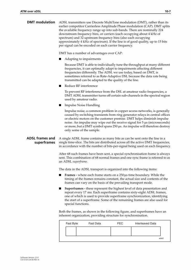
Both the frames, as shown in the following figure, and superframes have an inherent organization, providing structure for synchronisation.
adsl2
Fast Byte Fast Data FEC Interleaved Data
Software Version 2.9.1C613-03124-00 REV A
10-8 AlliedWare OS Software Reference
Each frame contains:
■ The Fast Byte is used for special superframe-related processing functions.
■ The Fast Data transmits time-sensitive information such as audio, and is not retransmitted. This can vary in length.
■ Forward Error Correction (FEC) is used to ensure the accuracy of the fast data.
■ Interleaved Data is the user data that the ADSL interface transmits, typically data network payload such as Internet data. This can vary in length.
FDM or EC ADSL can use either Echo Cancellation (EC) or Frequency Division Multiplexing (FDM) on the DSL subcarrier channels. Upstream data uses 25 subcarriers in both methods. FDM separates the upstream and downstream subcarriers, using 224 subcarriers for downstream data, while EC overlaps some of the upstream and downstream carriers to use 249 subcarriers for downstream data. EC is defined as optional in ITU-T Recommendation G.992.1 and may not be implemented by certain DSLAMs.
SHDSL
SHDSL networkcomponents
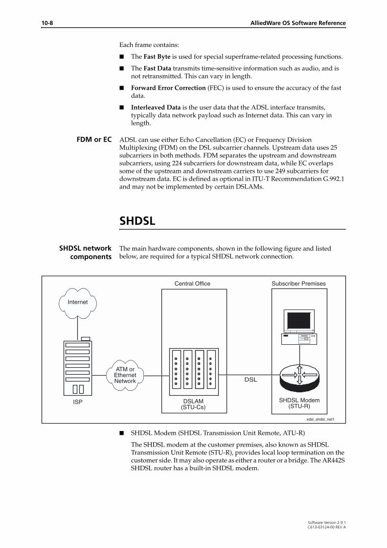
The main hardware components, shown in the following figure and listed below, are required for a typical SHDSL network connection.
■ SHDSL Modem (SHDSL Transmission Unit Remote, ATU-R)
The SHDSL modem at the customer premises, also known as SHDSL Transmission Unit Remote (STU-R), provides local loop termination on the customer side. It may also operate as either a router or a bridge. The AR442S SHDSL router has a built-in SHDSL modem.
xdsl_shdsl_net1
Internet
ATM or Ethernet Network
DSLAM (STU-Cs)
SHDSL Modem (STU-R)
ISP
Central Office Subscriber Premises
DSL
Software Version 2.9.1C613-03124-00 REV A
ATM over xDSL 10-9
■ SHDSL Transmission Unit Central Office (STU-C)
The SHDSL modem at the central office, or STU-C, terminates the SHDSL local loop at the central office premises. Many STU-Cs can be inserted into a DSLAM. The AR442S SHDSL router can operate in Central Office mode, as an STU-C.
■ DSL Access Multiplexor (DSLAM)
The STU-C units are collected together in a chassis unit called a DSLAM. The DSLAM can connect through an ATM or Ethernet access network to the Internet.
1-pair and2-pair modes
By default, the AR442S router’s SHDSL interface operates in 1-pair (2-wire) mode (using pins 3 and 4 only). This enables it to transmit over the single-pair cable commonly available in established telephone networks.
For increased speed, connect the router in 2-pair (4-wire) mode, using pins 3 and 4 for pair one, and pins 2 and 5 for pair two. Because the payload is equally divided between the two pairs, with equal data rates on each, data throughput is approximately doubled. From an application point of view, the 2-pair mode appears as a single interface.
Standard andEnhanced 2-pair
modes
On the AR442S router, the SHDSL interface offers both standards-based, and enhanced 2-pair, modes of operation. The standards-based 2-pair mode is compatible with ITU standard G.991.2 (12/2003). The Enhanced 2-pair mode was initially developed prior to the finalization of the standard, and is therefore not compatible with standards-based DSLAMs. Standards-based 2-pair mode is advisable for most installations, but enhanced mode may be useful in circumstances where it is compatible with the DSLAM.
SHDSL data rates Upstream data rates are the same as downstream rates for SHDSL. In single-pair mode data rates can be set to fixed speeds from 192 kbps (up to 6 km) to 2.3 Mbps (up to 3 km), in 16kbps intervals. 2-pair mode provides greater data rates (384kbps to 4.6 Mbps). On the AR442S router, you can set the data rate to a fixed rate (Table 10-4 on page 10-57), or set it to adapt to find the best rate available as conditions on the line vary. The two SHDSL frequency profiles are designed for optimal performance on slightly different wire gauges: Annex A for 26 AWG (American Wire Gauge), and Annex B for 0.4 mm gauge. The speeds that can be achieved in a particular situation also depend on line conditions (“Line conditions and performance” on page 10-4.)
Using Power Measurement Modulation Sessions (PMMS), also called Line Probes, SHDSL interfaces estimate the (signal-to-noise ratio (SNR) on the line, and assess whether they can provide particular data rates within a specified PMMS target margin. The interfaces on a line can then communicate to each other the data rates they can support under the real conditions of the line, either to confirm a fixed data rate, or to allow them to negotiate an adaptive rate.
Power Backoff During training, the SHDSL interfaces determine the power of the signals the two ends of the line transmit to each other. At longer distances, both ends transmit at full power. At shorter distances, they reduce the power of the signals they transmit, by 0 to 6dB.
Software Version 2.9.1C613-03124-00 REV A

10-10 AlliedWare OS Software Reference
Modulation SHDSL uses the Trellis Coded Pulse Amplitude Modulation (TC-PAM) format to provide rate adaptive performance over longer links. This format uses a frequency spectrum that makes SHDSL compatible with other DSL traffic, such as ADSL, in the same binder. The shape of the waveforms it transmits allows it to use relatively low power.
SHDSL frames SHDSL usually operates in synchronous mode, although it can also operate in plesiochronous (near-synchronous) mode. The following figure shows the format of SHDSL frames.
■ The frame synchronisation word (FSW) beginning each SHDSL frame is used to align frames.
■ The overhead between the FSW and payload blocks includes bits for the Embedded Operations Channel (EOC) for maintenance, error checking by Cyclic Redundancy Check (CRC), and further synchronisation.
■ The four payload blocks in an SHDSL frame are used to carry user data. These are each divided into 12 sub-blocks. If the SHDSL interface is operating in a 2-pair mode, the data is interleaved across the 12 sub-blocks on the two cable-pairs.
■ The stuffing bits at the end of each frame also support synchronisation.
Embedded Operations ChannelSTU-Cs and STU-Rs use the Embedded Operations Channel (EOC) channel for line management. When an SHDSL line is activated, the EOC detects and stores on both the STU-C and STU-R the address and location of the STU at the other end of the connection, and of any SHDSL Regenerator Units (SRUs) in between. The STU-C also configures other operational parameters, such as alarm thresholds and signal characteristics on the STU-R and SRUs.
On some SHDSL devices network administrators can send EOC commands to control aspects of the SHDSL line, primarily for diagnostic purposes. On the AR442S SHDSL router, use the activate shdsl eoccmd command on page 10-32 and the deactivate shdsl eoccmd command on page 10-37.
xdsl_shdsl_frame
Framesync
Payload block
StuffbitsOverhead
Payload block
Payload block
Payload block
12 Payload sub-blocks
OverheadOverheadOverhead
Software Version 2.9.1C613-03124-00 REV A
ATM over xDSL 10-11
ATM
Asynchronous Transfer Mode (ATM) is a high speed Link Layer (Layer 2) network protocol. ATM can be used to provide access to the physical layer, such as ADSL, for higher layer protocols such as PPP and TCP/IP. ATM is one of the key technologies for enabling broadband on ADSL, and is well suited to such purposes as realtime voice and video.
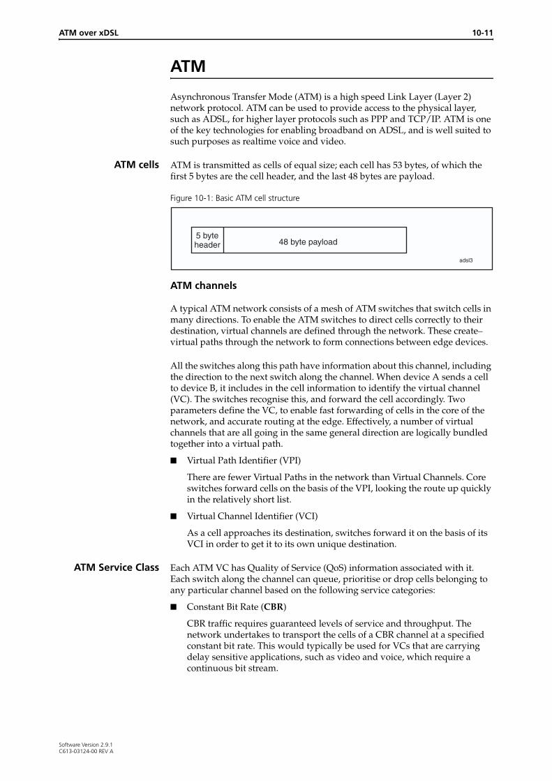
ATM cells ATM is transmitted as cells of equal size; each cell has 53 bytes, of which the first 5 bytes are the cell header, and the last 48 bytes are payload.
Figure 10-1: Basic ATM cell structure
ATM channels
A typical ATM network consists of a mesh of ATM switches that switch cells in many directions. To enable the ATM switches to direct cells correctly to their destination, virtual channels are defined through the network. These create virtual paths through the network to form connections between edge devices.
All the switches along this path have information about this channel, including the direction to the next switch along the channel. When device A sends a cell to device B, it includes in the cell information to identify the virtual channel (VC). The switches recognise this, and forward the cell accordingly. Two parameters define the VC, to enable fast forwarding of cells in the core of the network, and accurate routing at the edge. Effectively, a number of virtual channels that are all going in the same general direction are logically bundled together into a virtual path.
■ Virtual Path Identifier (VPI)
There are fewer Virtual Paths in the network than Virtual Channels. Core switches forward cells on the basis of the VPI, looking the route up quickly in the relatively short list.
■ Virtual Channel Identifier (VCI)
As a cell approaches its destination, switches forward it on the basis of its VCI in order to get it to its own unique destination.
ATM Service Class Each ATM VC has Quality of Service (QoS) information associated with it. Each switch along the channel can queue, prioritise or drop cells belonging to any particular channel based on the following service categories:
■ Constant Bit Rate (CBR)
CBR traffic requires guaranteed levels of service and throughput. The network undertakes to transport the cells of a CBR channel at a specified constant bit rate. This would typically be used for VCs that are carrying delay sensitive applications, such as video and voice, which require a continuous bit stream.
adsl3
5 byteheader 48 byte payload
Software Version 2.9.1C613-03124-00 REV A
10-12 AlliedWare OS Software Reference
■ Variable Bit Rate (VBR)
There are two variable bit rate service categories:
• Variable Bit Rate–non-real time (VBR-nrt) is used by applications that produce traffic of varying bit rates, which produce varying throughput rates, and which are able to tolerate delay (for example, email).
• Variable Bit Rate–real time (VBR-rt) is used by applications that produce traffic of varying bit rates, which produce varying throughput rates, and which are intolerant of delay. The network allows such a VC some leeway in its throughput rate, and undertakes to minimize latency in forwarding its cells.
■ Unspecified Bit Rate (UBR)
The UBR service category does not specify traffic related service guarantees. Specifically, UBR does not include a per-connection negotiated bandwidth. The network makes no numerical commitments about the cell loss ratio or the cell transfer delay for cells on a UBR VC.
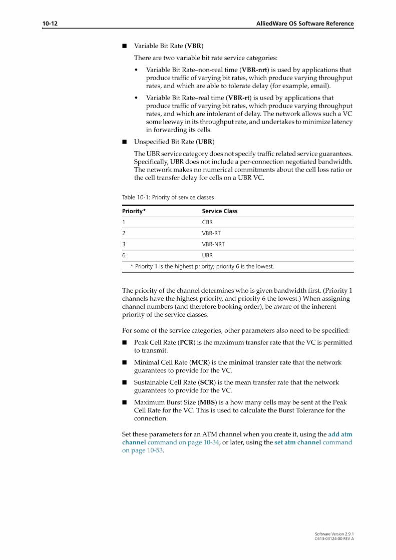
The priority of the channel determines who is given bandwidth first. (Priority 1 channels have the highest priority, and priority 6 the lowest.) When assigning channel numbers (and therefore booking order), be aware of the inherent priority of the service classes.
For some of the service categories, other parameters also need to be specified:
■ Peak Cell Rate (PCR) is the maximum transfer rate that the VC is permitted to transmit.
■ Minimal Cell Rate (MCR) is the minimal transfer rate that the network guarantees to provide for the VC.
■ Sustainable Cell Rate (SCR) is the mean transfer rate that the network guarantees to provide for the VC.
■ Maximum Burst Size (MBS) is a how many cells may be sent at the Peak Cell Rate for the VC. This is used to calculate the Burst Tolerance for the connection.
Set these parameters for an ATM channel when you create it, using the add atm channel command on page 10-34, or later, using the set atm channel command on page 10-53.
Table 10-1: Priority of service classes
Priority* Service Class
1 CBR
2 VBR-RT
3 VBR-NRT
6 UBR
* Priority 1 is the highest priority; priority 6 is the lowest.
Software Version 2.9.1C613-03124-00 REV A

ATM over xDSL 10-13
ATM Call Admission Control (CAC)Call Admission Control (CAC) stops oversubscription of bandwidth for an ATM interface and can prevent QOS service contract violations.
ATM CAC is available on the AR442S router only.
Without CAC, the router uses bandwidth on a link in the priority order of their service classes. Table 10-1 on page 10-12 shows the standard priority scheduling of service classes. The ATM channels with higher priority (for example, CBR) use the available bandwidth before channels with lower priority (for example UBR).
With CAC, the router books bandwidth for ATM channels in the order of their channel numbers. For example, it books bandwidth for ATM channel 1 first, then channel 2, then channel 3 and so on. If there is not enough bandwidth available for a channel, then the router does not book any bandwidth for it, the channel stays down, and the router tries to allocate bandwidth for the following channel. The channels that are booked use the available bandwidth according to their service class priority. So when you create ATM channels that will be controlled by CAC, you may want to give the higher priority channels lower channel numbers.
CAC books or rebooks all the channels on an ATM interface when:
■ the ATM instance comes up, if CAC is already enabled
■ CAC is enabled, if the ATM instance is already up
■ the available bandwidth changes because of line conditions
Enabling CAC To apply CAC to an ATM interface, use the command:
enable atm=0..9 CAC
To disable CAC on the interface, use the command:
disable atm=0..9 CAC
UBR allocation ATM channels with service class UBR have the lowest priority of all the service classes. How CAC books UBR channels depends on how you specify Peak Cell Rates (PCR):
■ If you specify a PCR, CAC books the channel the bandwidth specified by the PCR.
■ If you do not specify a PCR, by default CAC books the channel 32 kbps, for the purpose of calculating whether there is enough bandwidth for the channel to come up, and for calculating how much bandwidth is left to book further channels. These UBR channels then use as much bandwidth as is available, which may be more than the 32 kbps booked, up to the maximum bandwidth for the link. If there are two or more of these channels, they use equal shares of the available bandwidth.
■ If you specify a PCR for some UBR channels, and not for others, CAC books them as above. Then they use the available bandwidth according to the ratio of PCRs. When it comes to using the bandwidth, those with no PCR specified are counted as having a PCR of maximum bandwidth. For example, if three UBR channels have PCRs: 100, 200 and unspecified on a 400 Mbps link, then CAC books them at: 100, 200 and 32 kbps, and they use all available bandwidth in the ratio 1:2:4.
Software Version 2.9.1C613-03124-00 REV A

10-14 AlliedWare OS Software Reference
The default setting for CAC UBR allocation of 32 kbps suits most situations. To change it, use the command:
set atm=0..9 ubrallocation=32..8192
Overbooking By default, CAC books 100% of the available bandwidth on an interface. This default (100) suits most situations. You can change this setting to force CAC to book more than the currently available bandwidth; this is called overbooking. In some cases, overbooking may give statistically higher performance for VBR channels, because they can use all idle ATM cells for a link; it is unlikely to give higher performance for CBR or UBR channels, because they do not use such idle cells.
Caution Only use overbooking if you are certain of its effects. Overbooking inappropriately can violate QoS contracts for all channels on an ATM interface.
To force CAC to book more than the available bandwidth on a link, set the percentage booking by using the command:
set atm=0..9 overbooking=1..1000
For example, to book 1.1 Mbps on a 1 Mbps link (110%), set overbooking to 110 using the command:
set atm=0 overbooking=110
Example:Simple CBR and UBR
The following table shows a simple example of bandwidth allocation for two CBR and two UBR channels on a 1.5 Mbps link with CAC enabled or disabled.
Example:UBR bandwidth
sharing
The following table shows an example of bandwidth allocation for four UBR channels sharing bandwidth on a 1.2 Mbps link with CAC enabled or disabled. Two of the channels have a Peak Cell Rate (PCR) specified, and two have a default PCR, which is the maximum bandwidth for the link.
ATM channel
Service class
PCR Bandwidth used with CAC disabled
Bandwidth booked with CAC enabled
Bandwidth used with CAC enabled
1 CBR 500 500 500 500
2 CBR 500 500 500 500
3 UBR default 250 500 500
4 UBR default 250 0 0
ATM channel
Service class
PCR Bandwidth used with CAC disabled
Bandwidth booked with CAC enabled
Bandwidth used with CAC enabled
1 UBR 500 176 500 176
2 UBR 500 176 500 176
3 UBR default: max bandwidth: 1200
423 32 423
4 UBR default: max bandwidth: 1200
423 32 423
Software Version 2.9.1C613-03124-00 REV A
ATM over xDSL 10-15
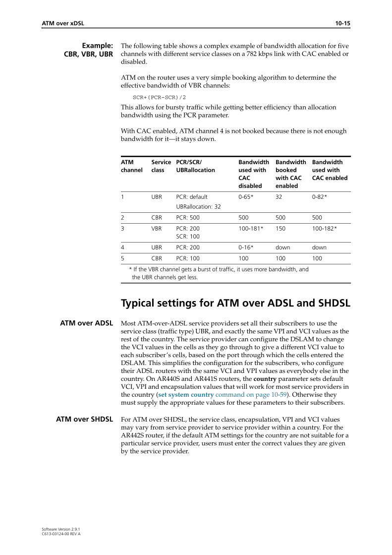
Example:CBR, VBR, UBR
The following table shows a complex example of bandwidth allocation for five channels with different service classes on a 782 kbps link with CAC enabled or disabled.
ATM on the router uses a very simple booking algorithm to determine the effective bandwidth of VBR channels:
SCR+(PCR-SCR)/2
This allows for bursty traffic while getting better efficiency than allocation bandwidth using the PCR parameter.
With CAC enabled, ATM channel 4 is not booked because there is not enough bandwidth for it—it stays down.
Typical settings for ATM over ADSL and SHDSL
ATM over ADSL Most ATM-over-ADSL service providers set all their subscribers to use the service class (traffic type) UBR, and exactly the same VPI and VCI values as the rest of the country. The service provider can configure the DSLAM to change the VCI values in the cells as they go through to give a different VCI value to each subscriber’s cells, based on the port through which the cells entered the DSLAM. This simplifies the configuration for the subscribers, who configure their ADSL routers with the same VCI and VPI values as everybody else in the country. On AR440S and AR441S routers, the country parameter sets default VCI, VPI and encapsulation values that will work for most service providers in the country (set system country command on page 10-59). Otherwise they must supply the appropriate values for these parameters to their subscribers.
ATM over SHDSL For ATM over SHDSL, the service class, encapsulation, VPI and VCI values may vary from service provider to service provider within a country. For the AR442S router, if the default ATM settings for the country are not suitable for a particular service provider, users must enter the correct values they are given by the service provider.
ATM channel
Service class
PCR/SCR/UBRallocation
Bandwidth used with CAC disabled
Bandwidth booked with CAC enabled
Bandwidth used with CAC enabled
1 UBR PCR: default
UBRallocation: 32
0-65* 32 0-82*
2 CBR PCR: 500 500 500 500
3 VBR PCR: 200 SCR: 100
100-181* 150 100-182*
4 UBR PCR: 200 0-16* down down
5 CBR PCR: 100 100 100 100
* If the VBR channel gets a burst of traffic, it uses more bandwidth, and the UBR channels get less.
Software Version 2.9.1C613-03124-00 REV A

10-16 AlliedWare OS Software Reference
Data Layers above ATM
ATM Application Layer 5 (AAL5) splits higher layer packets up and puts them into ATM cells for transmission, adding padding as necessary to form good ATM cells. At the receiving end of the link, it extracts the data from cells received, and passes them up to the higher layer.
Implementations of ATM commonly use one of the definitions in RFC 1483 for encapsulating different protocols in ATM cells, so that the receiving end can correctly identify the protocol:
■ Virtual Channel Multiplexing (VCMux): Using this method, multiple VCs are created on an ADSL link, and a different protocol can be sent over each VC. Then, the receiver knows that all the packets arriving on a particular VC belong to a particular protocol. Because the AAL5 frame contains information about which protocol it is carrying, more bandwidth is available for data.
■ LLC/SNAP encapsulation: In this method, only one VC is used. Extra headers are put into the front of data packets before they are passed to the AAL5 process to be cut up into ATM cells. The main purpose of these headers is to hold a field that specifies the protocol type of the enclosed data packet. RFC 1483 also defines two different types of LLC/SNAP headers: ‘RFC 1483 Routed’ and ‘RFC 1483 Bridged’. Because the AAL5 frames contain information about the protocol they are carrying, they are larger, and may provide slightly lower performance. This encapsulation is useful if more than one protocol, for example IP, PPP and ARP, are to be carried over a single channel.
On this router, the default encapsulation depends on the country setting (set system country command on page 10-59), and you can change it using the set atm channel command on page 10-53.
Connection Types Used over ATMThe DSLAM to which an ADSL modem connects may have either an ATM uplink port to an established ATM based network, or an Ethernet uplink port to connect to an Ethernet-based ADSL network. The following table shows how protocols can be combined and sent over AAL5 over ATM to suit different network architecture.
Type Description
PPPoA The logical choice for enabling individual clients to gain internet access over an ATM-based network. The PPP layer is introduced in order to make use of the already very popular features of PPP, such as authentication, link monitoring, IP address assignment, DNS address assignment. The exact format of the RFC 1483 header put onto the PPP packets is defined in RFC 2364.
PPPoE The logical choice for enabling individual clients to gain internet access over an Ethernet-based network (but it is sometimes used over ATM-based networks). As with PPPoA, it gets all the advantages of PPP, but at the cost of some extra packet overhead. The PPPoE packets are encapsulated using the RFC 1483 Bridged method.
Software Version 2.9.1C613-03124-00 REV A

ATM over xDSL 10-17
RFC 1483 Multiprotocol Encapsulation
As mentioned at the beginning of this section, RFC 1483 defines two basic encapsulations for carrying multiple protocols across an ATM network:
■ VC Based Multiplexing
■ LLC Encapsulation
VC Based MultiplexingUsing this method each higher level protocol is assigned a separate ATM virtual circuit (VC). This enables the router to identify which protocol each packet carries by reference to its VC number.
LLC EncapsulationUsing this method all protocols share the same ATM virtual circuit. The router identifies each protocol from fields within the AAL5 payload portion of the frame.
Interpretations of RFC 1483 Bridging and RoutingThe terms Routed and Bridged as used in RFC 1483 can be interpreted in different ways. An understanding of these interpretations will make it easier to find an ATM configuration that matches your requirements.
RFC 1483 defines formats for encapsulating protocols that are ‘bridged’, and protocols that are ‘routed’. The routed format encapsulates the layer-3 information directly within a specific RFC 1483 (LLC) header; whereas the bridged format also prepends a protocol specific field before encapsulating the layer-3 information within an RFC 1483 (LLC) header.
IPoA Designed in an attempt to make IP subnets map directly onto ATM networks in the same way that IP subnets map onto VLANs. So, an ATM address resolution protocol was introduced that enabled the IP stack to obtain the IP address for another IP host connected to its local ATM subnet (RFC 2225). The structure required to make this kind of network operate is rather complex, mostly because trying to make a channel-oriented transport like ATM appear like a broadcast domain is not a very natural fit.
RFC 1483 Bridged The whole Ethernet packet that arrives on the Ethernet side of the ADSL or SHDSL modem is encapsulated into AAL5 using the 'bridged-data' format defined in RFC 1483, and sent on the ADSL or SHDSL line. The modem forwards packets based on their MAC addresses, that is, it bridges the packets. (See also the definition in “RFC 1483 Multiprotocol Encapsulation”.)
RFC 1483 Routed Only the Layer 3 protocol frame is encapsulated with an RFC 1483 header in the AAL5 frame. The modem forwards packets based on their IP addresses; that is, it routes the packets. (See also the definition in “RFC 1483 Multiprotocol Encapsulation”.)
Type Description
Software Version 2.9.1C613-03124-00 REV A

10-18 AlliedWare OS Software Reference
Software Version 2.9.1
“RFC 1483 Routed”:Example
In this example, an AR440S router is configured for routing over an ATM/ADSL connection that is using RFC 1483 routed encapsulation. Its IP address is directly configured onto the ATM channel, using commands sequences such as:
enable adsl=0
create atm=0 over=adsl0
add atm=0 channel=1
enable ip
add ip interface=atm0.1 ipaddress=<address> mask=<subnetmask>
add ip route=0.0.0.0 int=atm0.1...next hop...
“IP Routed overRFC 1483 Bridged”:
Example
In this example an AR440S router is configured for routing over an ATM/ADSL connection that is using RFC 1483 bridged encapsulation. An IP address is configured over a virtual Ethernet interface on the subscriber’s ADSL port. This virtual ethernet interface informs the router to perform RFC 1483 bridged encapsulation as the frames are passed to the ATM layer.
enable adsl=0
create atm=0 over=adsl0
add atm=0 channel=1
create eth=0 over=atm0.1
enable ip
add ip interface=eth0 ipaddress=<address> mask=<subnet-mask>
add ip route=0.0.0.0 int=eth0...next hop...
“RFC 1483 Bridged”:Example
This example shows bridging over an ATM/ADSL connection that is using RFC 1483 bridged encapsulation. The virtual eth port is not explicitly configured because when an ATM channel is configured as a bridge port, the router automatically uses RFC 1483 bridged encapsulation on that interface.
ena adsl=0
create atm=0 over adsl0
add atm channel=1
ena bridge
add bridge port=1 int=vlan1
add bridge port=2 int=atm0.1
add bridge prot=ip type=0800
add bridge prot=arp type=0806
C613-03124-00 REV A

ATM over xDSL 10-19
Support on the Router
ADSL The AR440S ADSL router supports ADSL Annex A for connection to a POTS line. The AR441S ADSL router supports ADSL Annex B for connection to an ISDN line. The routers can be configured to use Frequency Division Multiplexing or Echo Cancellation. When an ADSL port is disabled or powered down, it sends a last Dying Gasp signal to indicate to the DSLAM that it is shutting down.
SHDSL The AR442S SHDSL router supports SHDSL variants ITU-T Recommendation G.991.2 Annex A (for 26AWG) and Annex B (for 0.4mm wire gauge), with or without an Access Network Frequency Plan (ANFP) PSD mask.
ATM The routers support ATM permanent virtual channels (PVCs), AAL5, and a number of higher layer protocols that can be configured over ATM and ADSL or SHDSL on the router as shown in Figure 10-2, and described in “Connection Types Used over ATM” on page 10-16:
■ PPPoE
■ PPPoA
■ IPoA
■ RFC 1483 Routed*
■ RFC 1483 Bridged*
* As defined in “RFC 1483 Multiprotocol Encapsulation” on page 10-17.
The router supports the following service categories:
■ Unspecified Bit Rate (UBR).
■ Constant Bit Rate (CBR).
■ Variable Bit Rate (VBR-rt and VBR-nrt). Of the two Cell Loss Priority algorithms that can be used for VBR, the router supports Type 1.
Software Version 2.9.1C613-03124-00 REV A

10-20 AlliedWare OS Software Reference
Figure 10-2: Protocols configured over ATM and ADSL
Virtual ETHinterfaces
You can create a virtual ETH interfaces in order to add an Ethernet header to packets before bridging the resulting Ethernet frames over a lower layer interface, such as an ATM channel over an ADSL or SHDSL port. Virtual ETH interfaces must not use an ETH instance number that is used by any of the physical ETH interfaces on the router.
Configuration Procedures and Examples
This section gives step by step procedures and simple configuration examples for configuring ATM over an ADSL port or an SHDSL port in CPE mode on the router.
■ “Configure PPPoE over ATM” on page 10-21
■ “Configure PPP over ATM (PPPoA)” on page 10-24
■ “Configure IP over ATM (IPoA)” on page 10-27
■ “Configure ATM RFC 1483 Routed” on page 10-29
Before youconfigure
Before you configure, you need the following information from your network service provider:
■ VPI (Virtual Path Identifier) and VCI (Virtual Circuit Identifier)
■ encapsulation mode—VCMUX (Virtual Circuit Multiplex) or LLCSNAP (also called AAL5SNAP)
■ access method, for example PPPoA, PPPoE, or IPoA
■ username and password, if using PPP
■ IP address assignment method—dynamic or static, if using PPP
Virtual Eth
RFC1483 Encapsulation
AAL5
ATM
ADSL
Bridge PPPoA
PPPoE
RFC1483 Routed
(no inverse ARP)
RFC1483 Bridged
Bridged Routed
IP IPoA (with
inverse ARP)
SHDSL
Software Version 2.9.1C613-03124-00 REV A

ATM over xDSL 10-21
Configure PPPoE over ATM
Procedure To configure PPPoE over ATM over ADSL or SHDSL, use the steps in the following table.
Step Commands Description
1 set system country={australia|austria|belgium|canada|denmark|eire|finland|france|germany|iceland|italy|netherlands|newzealand|norway|portugal|singapore|spain|switzerland|sweden|turkey|uae|uk|usa|none}
Set the country your router connects in, or omit this command to leave it at the default, none. The country setting determines default values for ATM channel parameters (vpi, vci, encapsulation).
2 set adsl=interface [autoretrain={on|off}] [standard={automatic|t1.413|g.dmt|g.lite}]
enable adsl={interface|all}
set shdsl=interface [mode={cpe|co}] [pairmode={1pair|2pairenhanced|2pairstandard}] [standard={annexa|annexb|both|annexbanfp|bothanfp}] [psdmask={symmetric|asymetric}] [autoretrain={on|off}] [bitratemode=adaptive|fixed] [minbitrate=72..4624] [maxbitrate=72..4624] [attenuationthreshold=0..31] [snrmarginthreshold=0..15]
enable shdsl={interface}
Configure and enable ADSL or SHDSL.
The default settings for ADSL and SHDSL allow it to automatically detect the ADSL or SHDSL standard to use, and to automatically retrain to make best use of the available bandwidth. Use the set adsl or set shdsl commands if you need to change from the default settings.
For SHDSL, the pairmode setting must be the same at both ends of the SHDSL link. For 4wire (2pair) mode, we also recommend setting the maxbitrate to the same value at both ends.
3 create atm=0..9 over=phys-interface Create an ATM instance to run over the ADSL or SHDSL interface. You can only configure one ATM instance on an ADSL or SHDSL interface.
4 add atm channel
add atm=0..9 channel=1..30 [serviceclass=ubr] [description=description] [pcr=32..155000] [encapsulation={aal5snap|llc|vcmux}][vpi=0..255 vci=32..1023]
add atm=0..9 channel=1..30 serviceclass=cbr pcr=32..155000 [description=description] [encapsulation={aal5snap|llc|vcmux}] [vpi=0..255 vci=32..1023]
add atm=0..9 channel=1..30 serviceclass={vbrnrt|vbrrt} pcr=32..155000 scr=32..155000 mbs=2..10000 [description=description] [encapsulation={aal5snap|llc|vcmux}] [vpi=0..255 vci=32..1023]
Add an ATM channel to the ATM instance. Change the defaults for the ATM channel if necessary.
5 create eth=0..7 over=interface Create a virtual Ethernet interface to encapsulate traffic over the ATM channel in Ethernet frames.
Software Version 2.9.1C613-03124-00 REV A

10-22 AlliedWare OS Software Reference
6 create ppp=ppp-interface over=physical-interface [iprequest={on|off}] [username=username] password=password] [other-ppp-parameters]
Create a PPP interface over the virtual Ethernet interface.Set PPP parameters as required. For instance:
To allow the IP address for the PPP link to be dynamically allocated, set iprequest to on.
Set the username and password for that will be used to respond to authentication requests.
7 enable ip
add ip interface=interface ipaddress={ipadd|dhcp} [other-ip-parameters]
Enable IP, and assign an IP address to the PPP interface, or set it to accept a dynamically allocated IP address.
Then continue with other configuration as required (“After configuring ATM” on page 10-30).
Step Commands Description
Software Version 2.9.1C613-03124-00 REV A

ATM over xDSL 10-23
Example The following figure shows a simple script for configuring PPPoE over ATM over ADSL. Modify it to suit your ATM network requirements, or to run over SHDSL.
# PPPoE over ATM over xDSL
# Enable the ADSL or SHDSL port.enable adsl=0
# Set the country for ATM default parameters.set system country=italy
# Create an ATM instance and channel over the ADSL port. create atm=0 over=adsl0add atm=0 channel=1
# Create a virtual Ethernet interface over the ATM channel.create eth=2 over=atm0.1
# Create a PPP interface over the virtual Eth interface, and # set it to accept a dynamically allocated IP address.cre ppp=0 over=eth2-any bap=off iprequest=on user="myname" pass="mypassword" lqr=off
# Enable IP and add an IP interface with remote IP address # assignment to the PPP interface.enable ipenable ip remoteadd ip interface=ppp0 ipaddress=0.0.0.0
# Add a local IP address to the default VLAN.add ip interface=vlan1 ipaddress=192.168.1.1
# Add a default IP route to the PPP interface.add ip route=0.0.0.0 interface=ppp0 next=0.0.0.0
Software Version 2.9.1C613-03124-00 REV A

10-24 AlliedWare OS Software Reference
Configure PPP over ATM (PPPoA)
Procedure To configure PPPoE over ATM (PPPoA) over ADSL or SHDSL, use the steps in the following table.
Step Commands Description
1 set system country={australia|austria|belgium|canada|denmark|eire|finland|france|germany|iceland|italy|netherlands|newzealand|norway|portugal|singapore|spain|switzerland|sweden|turkey|uae|uk|usa|none}
Set the country your router connects in, or omit this command to leave it at the default, none. The country setting determines default values for ATM channel parameters (vpi, vci, encapsulation).
2 set adsl=interface [autoretrain={on|off}] [standard={automatic|t1.413|g.dmt|g.lite}]
enable adsl={interface|all}
set shdsl=interface [mode={cpe|co}] [pairmode={1pair|2pairenhanced|2pairstandard}] [standard={annexa|annexb|both|annexbanfp|bothanfp}] [psdmask={symmetric|asymetric}] [autoretrain={on|off}] [bitratemode=adaptive|fixed] [minbitrate=72..4624] [maxbitrate=72..4624] [attenuationthreshold=0..31] [snrmarginthreshold=0..15]
enable shdsl={interface}
Configure and enable ADSL or SHDSL.
The default settings for ADSL and SHDSL allow it to automatically detect the ADSL or SHDSL standard to use, and to automatically retrain to make best use of the available bandwidth. Use the set adsl or set shdsl command if you need to change from the default settings.
For SHDSL, the pairmode setting must be the same at both ends of the SHDSL link. For 4wire (2pair) mode, we also recommend setting the maxbitrate to the same value at both ends.
3 create atm=0..9 over=phys-interface Create an ATM instance to run over the ADSL or SHDSL interface. You can only configure one ATM instance on an ADSL or SHDSL interface.
4 add atm channel
add atm=0..9 channel=1..30 [serviceclass=ubr] [description=description] [pcr=32..155000] [encapsulation={aal5snap|llc|vcmux}] [vpi=0..255 vci=32..1023]
add atm=0..9 channel=1..30 serviceclass=cbr pcr=32..155000 [description=description] [encapsulation={aal5snap|llc|vcmux}] [vpi=0..255 vci=32..1023]
add atm=0..9 channel=1..30 serviceclass={vbrnrt|vbrrt} pcr=32..155000 scr=32..155000 mbs=2..10000 [description=description] [encapsulation={aal5snap|llc|vcmux} [vpi=0..255 vci=32..1023]
Add an ATM channel to the ATM instance. Change the defaults for the ATM channel if necessary.
Software Version 2.9.1C613-03124-00 REV A
ATM over xDSL 10-25
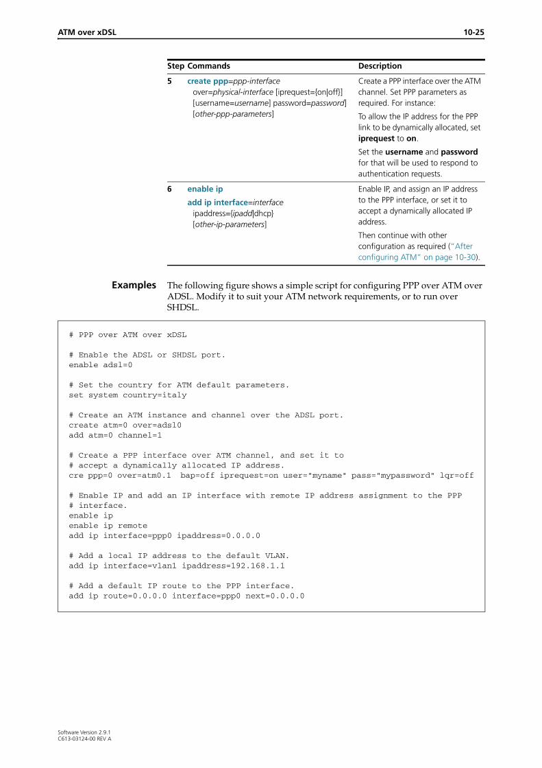
Examples The following figure shows a simple script for configuring PPP over ATM over ADSL. Modify it to suit your ATM network requirements, or to run over SHDSL.
5 create ppp=ppp-interface over=physical-interface [iprequest={on|off}] [username=username] password=password] [other-ppp-parameters]
Create a PPP interface over the ATM channel. Set PPP parameters as required. For instance:
To allow the IP address for the PPP link to be dynamically allocated, set iprequest to on.
Set the username and password for that will be used to respond to authentication requests.
6 enable ip
add ip interface=interface ipaddress={ipadd|dhcp} [other-ip-parameters]
Enable IP, and assign an IP address to the PPP interface, or set it to accept a dynamically allocated IP address.
Then continue with other configuration as required (“After configuring ATM” on page 10-30).
Step Commands Description
# PPP over ATM over xDSL
# Enable the ADSL or SHDSL port.enable adsl=0
# Set the country for ATM default parameters.set system country=italy
# Create an ATM instance and channel over the ADSL port. create atm=0 over=adsl0add atm=0 channel=1
# Create a PPP interface over ATM channel, and set it to # accept a dynamically allocated IP address.cre ppp=0 over=atm0.1 bap=off iprequest=on user="myname" pass="mypassword" lqr=off
# Enable IP and add an IP interface with remote IP address assignment to the PPP # interface.enable ipenable ip remoteadd ip interface=ppp0 ipaddress=0.0.0.0
# Add a local IP address to the default VLAN.add ip interface=vlan1 ipaddress=192.168.1.1
# Add a default IP route to the PPP interface.add ip route=0.0.0.0 interface=ppp0 next=0.0.0.0
Software Version 2.9.1C613-03124-00 REV A

10-26 AlliedWare OS Software Reference
The following figure shows a simple script for configuring PPP over ATM over SHDSL for two AR442S routers with their SHDSL ports connected to each other (back-to-back). Modify it to suit your ATM network requirements.
# PPP over ATM over SHDSL
# On one of the two routers, set the SHDSL port to CO (central office) mode; on the # other, leave the SHDSL port in the default CPE (customer premises equipment) mode. set shdsl=0 mode=co
# Enable the SHDSL port.enable shdsl=0
# Set the country for ATM default parameters.set system country=italy
# Create an ATM instance and channel over the ADSL port. create atm=0 over=adsl0add atm=0 channel=1
# Create a PPP interface over the atm channelcreate ppp=0 over=atm0.1
# Enable IP and add an IP interface to the PPP interface.enable ipadd ip interface=ppp0 ipaddress=10.10.10.1
# Add a local IP address to the default VLAN.add ip interface=vlan1 ipaddress=192.168.1.1
# Add a default IP route to the PPP interface.add ip route=0.0.0.0 int=ppp0 next=10.10.10.2
Software Version 2.9.1C613-03124-00 REV A

ATM over xDSL 10-27
Configure IP over ATM (IPoA)
Procedure To configure IP over ATM (IPoA) over ADSL or SHDSL, use the steps in the following table.
Step Command Description
1 set system country={australia|austria|belgium|canada|denmark|eire|finland|france|germany|iceland|italy|netherlands|newzealand|norway|portugal|singapore|spain|switzerland|sweden|turkey|uae|uk|usa|none}
Set the country your router connects in, or omit this command to leave it at the default, none. The country setting determines default values for ATM channel parameters (vpi, vci, encapsulation).
2 set adsl=interface [autoretrain={on|off}] [standard={automatic|t1.413|g.dmt|g.lite}]
enable adsl={interface|all}
set shdsl=interface [mode={cpe|co}] [pairmode={1pair|2pairestandard|2pairenhanced] [standard={annexa|annexb|both|annexbanfp|bothanfp}] [psdmask={symmetric|asymetric}] [autoretrain={on|off}] [bitratemode=adaptive|fixed] [minbitrate=72..4624] [maxbitrate=72..4624] [attenuationthreshold=0..31] [snrmarginthreshold=0..15]
enable shdsl={interface}
Configure and enable ADSL or SHDSL.
The default settings for ADSL and SHDSL allow it to automatically detect the ADSL or SHDSL standard to use, and to automatically retrain to make best use of the available bandwidth. Use the set adsl or set shdsl command if you need to change from the default settings.
For SHDSL, the pairmode setting must be the same at both ends of the SHDSL link. For 4wire (2pair) mode, we also recommend setting the maxbitrate to the same value at both ends.
3 create atm=0..9 over=phys-interface Create an ATM instance to run over the ADSL or SHDSL interface. You can only configure one ATM instance on an ADSL or SHDSL interface.
4 add atm channel
add atm=0..9 channel=1..30 [serviceclass=ubr] [description=description] [pcr=32..155000] [encapsulation={aal5snap|llc|vcmux}][vpi=0..255 vci=32..1023]
add atm=0..9 channel=1..30 serviceclass=cbr pcr=32..155000 [description=description] [encapsulation={aal5snap|llc|vcmux}] [vpi=0..255 vci=32..1023]
add atm=0..9 channel=1..30 serviceclass={vbrnrt|vbrrt} pcr=32..155000 scr=32..155000 mbs=2..10000 [description=description] [encapsulation={aal5snap|llc|vcmux}] [vpi=0..255 vci=32..1023]
Add an ATM channel to the ATM instance.
Software Version 2.9.1C613-03124-00 REV A

10-28 AlliedWare OS Software Reference
Example The following figure shows a simple script for configuring IP over ATM over ADSL (IPoA). Modify it to suit your ATM network requirements, or to run over SHDSL.
5 enable ip
add ip interface=interface ipaddress={ipadd|dhcp} inversearp=on [other-ip-parameters]
Enable IP, assign a static IP address to the ATM channel, and enable Inverse ARP on the IP interface.
Then continue with other configuration as required (“After configuring ATM” on page 10-30).
Step Command Description
# IP over ATM over xDSL
# Enable the ADSL or SHDSL port.enable adsl=0
# Set the country for ATM default parameters.set system country=denmark
# Create an ATM instance and channel over the ADSL port. create atm=0 over=adsl0add atm=0 channel=1
# Enable IP and add an IP interface with inverse ARP enabled # to the ATM channel.enable ipadd ip interface=atm0.1 ipaddress=203.36.10.12 inversearp=on
# Add a local IP address to the default VLAN.add ip interface=vlan1 ipaddress=192.168.1.1
# Add a default IP route to the ATM channel.add ip route=0.0.0.0 interface=atm0.1 next=203.36.10.24
Software Version 2.9.1C613-03124-00 REV A

ATM over xDSL 10-29
Configure ATM RFC 1483 Routed
ProcedureTable 10-2: RFC 1483 Routed ATM over xDSL configuration procedure
Step Command Description
1 set system country={australia|austria|belgium|canada|denmark|eire|finland|france|germany|iceland|italy|netherlands|newzealand|norway|portugal|singapore|spain|switzerland|sweden|turkey|uae|uk|usa|none}
Set the country your router connects in, or omit this command to leave it at the default, none. The country setting determines default values for ATM channel parameters (vpi, vci, encapsulation).
2 set adsl=interface [autoretrain={on|off}] [standard={automatic|t1.413|g.dmt|g.lite}]
enable adsl={interface|all}
set shdsl=interface [mode={cpe|co}] [pairmode={1pair|2pair|2pairstandard|2pairenhanced}] [standard={annexa|annexb|both|annexbanfp|bothanfp}] [psdmask={symmetric|asymetric}] [autoretrain={on|off}] [bitratemode=adaptive|fixed] [minbitrate=72..4624] [maxbitrate=72..4624] [attenuationthreshold=0..31] [snrmarginthreshold=0..15]
enable shdsl={interface}
Configure and enable ADSL or SHDSL.
The default settings for ADSL and SHDSL allow it to automatically detect the ADSL or SHDSL standard to use, and to automatically retrain to make best use of the available bandwidth. Use the set adsl or set shdsl command if you need to change from the default settings.
For SHDSL, the pairmode setting must be the same at both ends of the SHDSL link. For 4wire (2pair) mode, we also recommend setting the maxbitrate to the same value at both ends.
3 create atm=0..9 over=phys-interface Create an ATM instance to run over the ADSL or SHDSL interface. You can only configure one ATM instance on an ADSL or SHDSL interface.
4 add atm channel
add atm=0..9 channel=1..30 [serviceclass=ubr] [description=description] [pcr=32..155000] [encapsulation={aal5snap|llc|vcmux}] [vpi=0..255 vci=32..1023]
add atm=0..9 channel=1..30 serviceclass=cbr pcr=32..155000 [description=description] [encapsulation={aal5snap|llc|vcmux}] [vpi=0..255 vci=32..1023]
add atm=0..9 channel=1..30 serviceclass={vbrnrt|vbrrt} pcr=32..155000 scr=32..155000 mbs=2..10000 [description=description] [encapsulation={aal5snap|llc|vcmux}] [vpi=0..255 vci=32..1023]
Add an ATM channel to the ATM instance.
Software Version 2.9.1C613-03124-00 REV A

10-30 AlliedWare OS Software Reference
Example The following figure shows a simple script for configuring RFC 1483 Routed ATM over ADSL with DHCP. Modify it to suit your ATM network requirements, or to run over SHDSL.
Figure 10-3: RFC 1483 Routed ATM over ADSL with DHCP configuration example
After configuring ATM
Once you have configured ATM over xDSL, you may need to configure other aspects of the router, for instance:
■ PPP backup link on ISDN (see Chapter 11, Integrated Services Digital Network (ISDN), Chapter 15, Point-to-Point Protocol (PPP))
■ Switch ports and VLANs (see Chapter 8, Switching)
■ IP routes, local VLAN IP addresses, and DNS Relay (see Chapter 22, Internet Protocol (IP))
■ IP Security for a Virtual Private Network (VPN) (see Chapter 48, IP Security (IPsec))
■ Firewall and Network Address Translation (NAT) (see Chapter 46, Firewall)
■ SNMP Community (see Chapter 55, Simple Network Management Protocol (SNMP))
■ DHCP server for local VLANs (see Chapter 23, Dynamic Host Configuration Protocol (DHCP))
5 enable ip
add ip interface=interface ipaddress={ipadd|dhcp} [other-ip-parameters]
Enable IP and assign an IP address to the ATM virtual channel interface.
Then continue with other configuration as required (“After configuring ATM” on page 10-30).
Table 10-2: RFC 1483 Routed ATM over xDSL configuration procedure (cont.)
Step Command Description
# RFC 1483 Routed ATM over xDSL
# Enable the ADSL or SHDSL port.enable adsl=0
# Set the country for ATM default parameters.set system country=denmark
# Create an ATM instance and channel over the ADSL port. create atm=0 over=adsl0add atm=0 channel=1
# Enable IP and add an IP interface with DHCP assigned IP # address to the ATM interface.enable ipenable ip remoteadd ip interface=atm0.1 ipaddress=192.168.2.1
# Add a local IP address to the default VLAN.add ip interface=vlan1 ipaddress=192.168.1.1
Software Version 2.9.1C613-03124-00 REV A

ATM over xDSL activate atm channel oamfunction 10-31
Command Reference
This section describes the commands available for configuring and monitoring ADSL, SHDSL and ATM on the router.
The shortest valid command is denoted by capital letters in the Syntax section. See “Conventions” on page lxv of About this Software Reference for additional conventions used to describe command syntax. See Appendix A, Messages for a complete list of messages and meanings.
activate atm channel oamfunction
Syntax ACTivate ATM=instance CHANnel=channel OAMfunction=LOopback TYpe=[F4Ete|F4Seg|F5Ete|F5Seg]
Description This command activates or initiates an OAM (operation and maintenance) function.
Examples To loopback a cell at the end of the channel, use the command:
act atm=0 chan=1 oam=lo ty=f5e
Related Commands delete atm channeldisable atm channelenable atm channelset atm channelshow atm channel
Parameter Description
ATM The ATM instance to use for OAM, in the range 0 to 9.
CHANnel The virtual channel to use for OAM, in the range 1 to 30.
OAMfunction The OAM function to activate.
LOopback Loopback is normally considered to be the ATM equivalent of PING and is sometimes called "ATM ping".
TYpe The maintenance plane for the loopback.
F4Ete F4 (path) end to end loopback: cells travel to the end of the path, then loopback to the originator.
F4Seg F4 (path) segment loopback: cells travel to the end of the closest path segment, usually the next connection point for the ATM network, then loopback to the originator.
F5Ete F5 (channel) end to end loopback: cells travel to the end of the channel, then loopback to the originator.
F5Seg F5 (channel) segment loopback: cells travel to the end of the closest channel segment, usually the next connection point for the ATM network, then loopback to the originator.
Software Version 2.9.1C613-03124-00 REV A

10-32 activate shdsl eoccmd AlliedWare OS Software Reference
activate shdsl eoccmd
Syntax ACTivate SHDsl=interface EOCcmd={LOOPback|SOFTrestart|MAPping} DEStination={1..A|F|ALL|CO|CPE} [LOOPbacktype={CUSTomer|NETwork|BOTH}] [TIMEOut={NONE|1..4095}]
Description This command sends an EOC command to one or more SHDSL connection points on the line.
Parameter Description
SHDsl The number of the SHDSL interface to send the command from.
EOCcmd The EOC command to send.
LOOPback The router instructs units on the line to enter the loopback mode determined by the loopbacktype parameter. If you specify loopback, you must also specify the loopbacktype and timeout parameters.
If the destination is all, the SHDSL interface sends a system loopback message (G.991.2 section 9.5.5.7.18); otherwise it sends an element loopback message (G.991.2 section 9.5.5.7.19).
SOFTRestart The router instructs units on the line to soft restart the SHDSL interface. The receiving units wait 5 seconds before restarting the interface.
MAPping The router sends a mapping request to units on the line. The mapping response message sent to the console shows which pair is connected to which DSLAM port.
DEStination The destination for the EOC command. (The source address is determined by the mode the unit is set to: 1 (CO) or 2 (CPE).)
CO, 1 The CO end.
CPE, 2 The CPE end.
3..A Repeaters 1 to 8 on the line, in hexadecimal format (3,4,5,6,7,8,9,10, or A).
All, F Broadcast to all units.
LOOPbacktype The type of loopback to configure.
The router cannot loopback in both directions at once.
Caution If you enable an internal loopback on another device, that is, a customer loopback on a CPE or a network loopback on a CO, then the device cannot receive or transmit on the EOC channel. This means that you cannot deactivate the loopback and must wait for the timeout.
CUSTomer The router instructs the units to configure the loopback towards the customer.
NETwork The router instructs the units to configure the loopback towards the network.
BOTH The router instructs the units to configure the loopback in both directions.
Software Version 2.9.1C613-03124-00 REV A
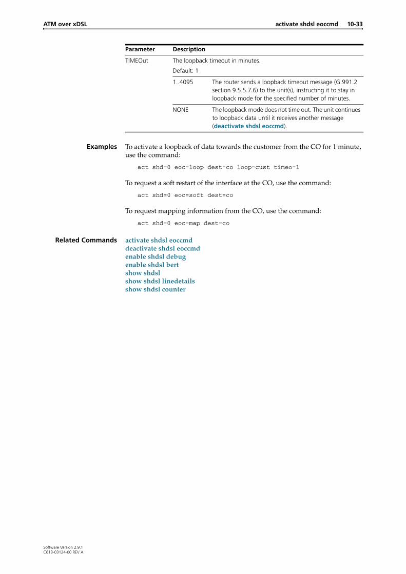
ATM over xDSL activate shdsl eoccmd 10-33
Examples To activate a loopback of data towards the customer from the CO for 1 minute, use the command:
act shd=0 eoc=loop dest=co loop=cust timeo=1
To request a soft restart of the interface at the CO, use the command:
act shd=0 eoc=soft dest=co
To request mapping information from the CO, use the command:
act shd=0 eoc=map dest=co
Related Commands activate shdsl eoccmddeactivate shdsl eoccmdenable shdsl debugenable shdsl bertshow shdslshow shdsl linedetailsshow shdsl counter
TIMEOut The loopback timeout in minutes.
Default: 1
1..4095 The router sends a loopback timeout message (G.991.2 section 9.5.5.7.6) to the unit(s), instructing it to stay in loopback mode for the specified number of minutes.
NONE The loopback mode does not time out. The unit continues to loopback data until it receives another message (deactivate shdsl eoccmd).
Parameter Description
Software Version 2.9.1C613-03124-00 REV A

10-34 add atm channel AlliedWare OS Software Reference
add atm channel
Syntax ADD ATM=instance CHANnel=channel [SERViceclass=UBR] [PCR=0|32..155000] [DESCription=description] [ENCapsulation={AAL5Snap|LLC|VCMux}] [VPI=0..15 VCI=32..1023]
ADD ATM=0..9 CHANnel=1..30 SERViceclass=CBR PCR=1..155000 [DESCription=description] [ENCapsulation={AAL5Snap|LLC|VCMux}] [VPI=0..15 VCI=32..1023]
ADD ATM=0..9 CHANnel=1..30 SERViceclass={VBRNrt|VBRRt} PCR=1..155000 SCR=1..155000 MBS=2..10000 [DESCription=description] [ENCapsulation={AAL5Snap|LLC|VCMux}] [VPI=0..15 VCI=32..1023]
Description This command creates an ATM (AAL5) virtual channel for the ATM instance. This channel can be referred to as atminstance.channel in other commands, for example, atm0.1 is virtual channel 1 on ATM instance 0.
Parameter Description
ATM The ATM instance to create the virtual channel on, in the range 0 to 9.
CHANnel The virtual channel to create, in the range 1 to 30.
DESCription Description of the channel for administration, up to 62 characters long. It has no effect on the operation of the channel.
ENCapsulation The RFC 1483 encapsulation mode to be used by the instance.
Default is determined by the country parameter set using the set system country command on page 10-59. If the country parameter has the default value of none, then the default for encapsulation is llc.
LLC, AAL5Snap
Logical Link Control mode; a single virtual channel can be used by different protocols.
VCMux Virtual Channel Multiplex mode; each protocol uses a separate virtual channel.
MBS The Maximum Burst Size for the channel, used to calculate the Burst Tolerance for the channel, in the range 2 to 10000. It is required if serviceclass is vbrrt or vbrnrt; otherwise not valid.
PCR The VC Peak Cell Rate in kbps.
Valid values are from 32 to Max Tx VC bit rate, as displayed using the show atm command on page 10-66, up to a maximum of 155000.
Required if serviceclass is cbr, vbrrt or vbrnrt (from service provider contract). Optional if serviceclass is ubr.
Default: maximum channel bandwidth (changes dynamically with the bandwidth)
To restore the channel’s UBR behaviour after pcr has been set, either:
• delete the channel and add it with no pcr value,
• disable the channel and specify pcr=0 using the set atm channel command on page 10-53.
SCR The VC Sustainable Cell Rate, in kbps.
In the range 32..155000.
Required if serviceclass is vbrnrt or vbrrt; otherwise not valid.
Software Version 2.9.1C613-03124-00 REV A

ATM over xDSL add atm channel 10-35
Examples To add virtual channel 1 to ATM instance 0 use the command:
add atm=0 chan=1
To add virtual channel 1 to ATM instance 0 with a VPI of 1, a VCI of 35, and real-time variable bit rate with Peak Cell Rate of 1Mb and Sustainable Cell Rate of 1Mb, use the command:
add atm=0 chan=1 vpi=1 vci=35 serv=vbrr pcr=1000 scr=1000
To add virtual channel 20 to ATM instance 0 with a VPI of 15, a VCI of 40, a Virtual Channel Multiplexed encapsulation, an Unspecified Bit Rate (default) with Peak Cell Rate of 10Mb, use the command:
add atm=0 chan=20 vpi=15 vci=40 encap=vcm pcr=10000
Related Commands create eth in Chapter 9, Interfacesdelete atm channeldisable atm channelenable atm channelset atm channelset system countryshow atm channel
SERViceclass Specifies the service category for the channel.
Default: ubr
CBR Constant Bit Rate.
UBR Unspecified Bit Rate.
VBRNrt Variable Bit Rate non-realtime.
VBRRt Variable Bit Rate realtime.
VCI The Virtual Channel Identification number.
In the range 32 to 1023.
Default is determined by the set system country command on page 10-59. If country is none, the default is 32.
VPI The Virtual Path Identification number.
In the range 0 to 15.
Default is determined by the set system country command on page 10-59. If country is none, the default is 0.
Parameter Description
Software Version 2.9.1C613-03124-00 REV A

10-36 create atm AlliedWare OS Software Reference
create atm
Syntax CREate ATM=0..9 OVer=phys-interface
Description This command creates an ATM instance running over a physical interface. One ATM instance can be created over an ADSL or SHDSL interface.
Examples To create ATM interface 0 over ADSL interface 0, use the command:
cre atm=0 ov=adsl0
Related Commands add atm channeldestroy atmshow atm
Parameter Description
ATM The number of the ATM instance to create, in the range 0 to 9. There can only be one ATM instance on a physical interface. (For instance, on the AR440S there can only be one ATM instance over the one ADSL interface.)
OVer The name of physical interface to create the ATM instance over, formed by concatenating the physical interface type with an interface instance (e.g. adsl0). Valid interface types are ADSL or SHDSL.
Software Version 2.9.1C613-03124-00 REV A

ATM over xDSL deactivate shdsl eoccmd 10-37
deactivate shdsl eoccmd
Syntax DEACTivate SHDsl=interface EOCcmd=LOOPback DEStination={1..A|F|ALL|CO|CPE} LOOPbacktype={CUSTomer|NETwork|BOTH}
Description This command sends an EOC command on the specified SHDSL interface to one or more connection points attached to the line to terminate loopback mode.
Examples To stop the loopback in the customer direction at the central office, use the command:
deact shd=0 eoc=loop dest=co loop=cust
Related Commands activate shdsl eoccmd
Parameter Description
SHDsl The number of the SHDSL interface to send the command from.
EOCcmd The EOC command to send:
LOOPback Instructs units on the line to exit a loopback determined by the loopbacktype parameter.
If the destination is all, the SHDSL interface sends a system loopback message; otherwise it sends an element loopback message (G.991.2 section 9.5.5.7).
DEStination The destination for the EOC command. (The source address is determined by the mode the unit is set to: 1 (CO) or 2 (CPE).)
CO, 1 The Central Office end.
CPE, 2 The Customer Premises Equipment end.
3..A Repeaters 1-8 in on the line, in hexadecimal format (3,4,5,6,7,8,9,10 or A).
All, F Broadcast to all units.
LOOPbacktype The type of loopback to terminate.
CUSTomer Instructs the unit to terminate the loopback towards the customer.
NETwork Instructs the unit to terminate the loopback towards the network.
BOTH Instructs the unit to terminate the loopback in both directions.
Software Version 2.9.1C613-03124-00 REV A

10-38 delete atm channel AlliedWare OS Software Reference
delete atm channel
Syntax DELete ATM=0..9 CHANnel=1..30
Description This command deletes an ATM virtual channel from the ATM instance. The instance must exist and is no longer be available after it is deleted. A channel cannot be deleted when a higher layer protocol is attached to it.
Examples To delete virtual channel 1 on ATM instance 0, use the command:
del atm=0 chan=1
Related Commands add atm channeldisable atm channelenable atm channelshow atm channel
destroy atm
Syntax DESTroy ATM=0..9
Description This command destroys an ATM instance. The instance must already exist. The instance is no longer available for use by routing modules. The ATM instance can only be destroyed if there are no virtual channels present on the instance. Virtual channels can be deleted using the delete atm channel command.
The ATM parameter specifies which ATM instance number to destroy, in the range 0 to 9.
Examples To destroy ATM instance 0, use the command:
dest atm=0
Related Commands create atmdelete atm channelset atm channelshow atm
Parameter Description
ATM The ATM instance the channel is on, in the range 0 to 9.
CHANnel The virtual channel to delete, in the range 1 to 30.
Software Version 2.9.1C613-03124-00 REV A
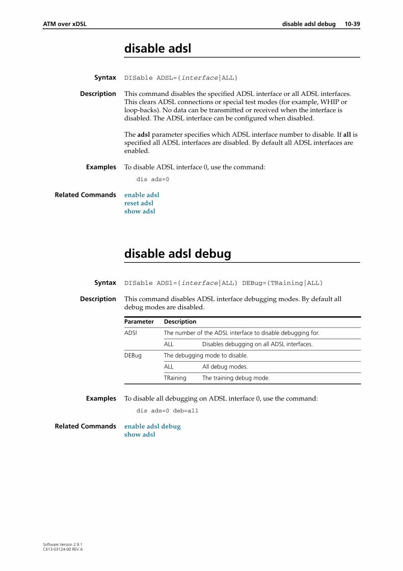
ATM over xDSL disable adsl debug 10-39
disable adsl
Syntax DISable ADSL={interface|ALL}
Description This command disables the specified ADSL interface or all ADSL interfaces. This clears ADSL connections or special test modes (for example, WHIP or loop-backs). No data can be transmitted or received when the interface is disabled. The ADSL interface can be configured when disabled.
The adsl parameter specifies which ADSL interface number to disable. If all is specified all ADSL interfaces are disabled. By default all ADSL interfaces are enabled.
Examples To disable ADSL interface 0, use the command:
dis ads=0
Related Commands enable adslreset adslshow adsl
disable adsl debug
Syntax DISable ADSl={interface|ALL} DEBug={TRaining|ALL}
Description This command disables ADSL interface debugging modes. By default all debug modes are disabled.
Examples To disable all debugging on ADSL interface 0, use the command:
dis ads=0 deb=all
Related Commands enable adsl debugshow adsl
Parameter Description
ADSl The number of the ADSL interface to disable debugging for.
ALL Disables debugging on all ADSL interfaces.
DEBug The debugging mode to disable.
ALL All debug modes.
TRaining The training debug mode.
Software Version 2.9.1C613-03124-00 REV A

10-40 disable atm cac AlliedWare OS Software Reference
disable atm cac
Syntax DISable ATM=0..9 CAC
Description This command disables ATM Call Admission Control (CAC) on the specified ATM instance. By default CAC is disabled on an instance.
Examples To disable call admission control for ATM instance 0, use the command:
dis atm=0 cac
Related Commands enable atm cacset atm cac
disable atm channel
Syntax DISable ATM=0..9 CHANnel={1..30|ALL}
Description This command disables an ATM virtual channel. No data is transmitted or received on the channel. By default an ATM channel is enabled when it is added.
Examples To disable virtual channel 1 in ATM instance 0, use the command:
dis atm=2 chan=1
Related Commands delete atm channelenable atm channelshow atm channel
Parameter Description
ATM The number of the ATM instance, in the range 0 to 9.
CHANnel The number of the ATM virtual channel to disable, in the range 1 to 30.
Software Version 2.9.1C613-03124-00 REV A

ATM over xDSL disable shdsl bert 10-41
disable shdsl
Syntax DISable SHDsl=interface
Description This command disables the specified SHDSL interface, and clears any SHDSL connection or special mode (for example, loop-backs). No data can be transmitted or received when the interface is disabled. The SHDSL interface can only be configured (set shdsl) when disabled. The default for an SHDSL interface is disabled.
Examples To disable SHDSL interface 0, use the command:
dis shd=0
Related Commands enable shdslreset shdslset shdslshow shdsl
disable shdsl bert
Syntax DISable SHDsl=interface BERT
Description This command disables a bit error rate test (BERT) on the specified SHDSL instance. Stopping a BERT session may desynchronise the SHDSL framer; we recommend setting autoretrain to off at both ends of the test, using the set shdsl command on page 10-55.
Examples To disable a BERT on SHDSL interface 0, use the command:
dis shd=0 bert
Related Commands enable shdsl bertshow shdsl
Software Version 2.9.1C613-03124-00 REV A

10-42 disable shdsl debug AlliedWare OS Software Reference
disable shdsl debug
Syntax DISable SHDsl=interface DEBug={ALARM|EOC|TRAINing|ALL}
Description This command disables SHDSL interface debug modes on the specified SHDSL interface. By default all debug modes are disabled.
Examples To disable all debug modes on SHDSL interface 0, use the command:
dis shd=0 deb=all
Related Commands enable shdsl debug
enable adsl
Syntax ENAble ADSl={interface|ALL}
Description This command enables a previously disabled ADSL interface, so that data can be transmitted or received on the interface. By default ADSL interfaces are disabled.
The adsl parameter specifies which ADSL interface to enable. If all is specified, all ADSL interfaces are enabled.
Examples To enable ADSL interface 0, use the command:
ena ads=0
Related Commands create atmdisable adslreset adslshow adsl
Parameter Description
SHDsl The SHDSL interface on which to disable debugging.
DEBug The debugging mode to disable.
ALARM Disables SHDSL alarm messages to the console.
EOC Disables embedded operations channel (EOC) debug information.
TRAINing Disables training debug information.
ALL Disables all SHDSL debugging.
Software Version 2.9.1C613-03124-00 REV A

ATM over xDSL enable atm cac 10-43
enable adsl debug
Syntax ENAble ADSl={interface|ALL} DEBug={ALL|TRaining} [TTy=tty-num]
Description This command enables ADSL interface debugging on an ADSL interface, or on all ADSL interfaces. By default all debugging modes are disabled.
Examples To enable all debugging modes on ADSL interface 0, use the command:
ena ads=0 deb=all
Related Commands disable adsl debug
enable atm cac
Syntax ENAble ATM=0..9 CAC
Description This command enables ATM Call Admission Control (CAC) on the specified ATM instance immediately. By default CAC is disabled on an instance. For more information about CAC, see “ATM Call Admission Control (CAC)” on page 10-13.
ATM CAC is available on the AR442S router only.
Examples To enable call admission control for ATM instance 0, use the command:
ena atm=0 cac
Related Commands disable atm cacset atm cac
Parameter Description
ADSl The number of the ADSL interface on which to enable debugging.
ALL Enables debugging on all ADSL interfaces.
DEBug The debugging mode to enable.
ALL All debug modes.
TRaining Displays the current ADSL connection status.
TTy The TTY instance number of the ASYN port or telnet session (terminal device) to send the debug output to. This enables debugging to be enabled in a script. To display the TTY instance number of the terminal device that is currently being used, use the show tty command on page 61-30 of Chapter 61, Terminal Server.
Default: the terminal or Telnet session from which the command was executed.
Software Version 2.9.1C613-03124-00 REV A

10-44 enable atm channel AlliedWare OS Software Reference
enable atm channel
Syntax ENAble ATM=instance CHANnel={1..30|ALL}
Description This command enables a previously disabled ATM virtual channel, or all channels on an ATM instance. Data can be transmitted or received on the channel. By default an ATM channel is enabled.
Examples To enable all virtual channels on ATM instance 0, use the command:
ena atm=0 chan=all
Related Commands add atm channeldelete atm channeldisable atm channelenable adslset atm channelshow atm channel
enable shdsl
Syntax ENAble SHDsl=interface
Description This command enables the specified SHDSL interface. The default is disabled.
Examples To enable SHDSL interface 0, use the command:
ena shd=0
Related Commands disable shdslreset shdslset shdslshow shdsl
Parameter Description
ATM The number of the ATM instance, in the range 0 to 9.
CHANnel The number of the ATM virtual channel to enable, in the range 1 to 30.
Software Version 2.9.1C613-03124-00 REV A

ATM over xDSL enable shdsl bert 10-45
enable shdsl bert
Syntax ENAble SHDsl=interface BERT
Description This command enables a bit error rate test (BERT) on the specified SHDSL interface. Before a BERT can be conducted the SHDSL interface must have successfully trained in data, analogloopback or digitalloopback modes.
If a BERT is to be conducted in data mode, the remote unit must also be performing a BERT. Starting a BERT session may desynchronise the SHDSL framer; we recommend setting autoretrain to off at both ends of the test, using the set shdsl command on page 10-55.
Examples To enable a BERT on SHDSL interface 0, use the command:
ena shd=0 bert
Related Commands disable shdsl bertshow shdsl
Software Version 2.9.1C613-03124-00 REV A
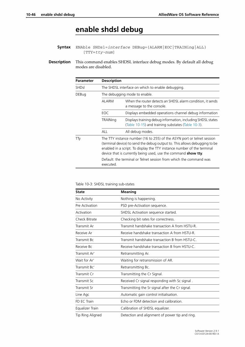
10-46 enable shdsl debug AlliedWare OS Software Reference
enable shdsl debug
Syntax ENAble SHDsl=interface DEBug={ALARM|EOC|TRAINing|ALL} [TTY=tty-num]
Description This command enables SHDSL interface debug modes. By default all debug modes are disabled.
Parameter Description
SHDsl The SHDSL interface on which to enable debugging.
DEBug The debugging mode to enable.
ALARM When the router detects an SHDSL alarm condition, it sends a message to the console.
EOC Displays embedded operations channel debug information
TRAINing Displays training debug information, including SHDSL states (Table 10-15) and training substates (Table 10-3).
ALL All debug modes.
TTy The TTY instance number (16 to 255) of the ASYN port or telnet session (terminal device) to send the debug output to. This allows debugging to be enabled in a script. To display the TTY instance number of the terminal device that is currently being used, use the command show tty.
Default: the terminal or Telnet session from which the command was executed.
Table 10-3: SHDSL training sub-states
State Meaning
No Activity Nothing is happening.
Pre Activation PSD pre-Activation sequence.
Activation SHDSL Activation sequence started.
Check Bitrate Checking bit rates for correctness.
Transmit Ar Transmit handshake transaction A from HSTU-R.
Receive Ar Receive handshake transaction A from HSTU-R.
Transmit Bc Transmit handshake transaction B from HSTU-C.
Receive Bc Receive handshake transaction B from HSTU-C.
Transmit Ar' Retransmitting Ar.
Wait for Ar' Waiting for retransmission of AR.
Transmit Bc' Retransmitting Bc.
Transmit Cr Transmitting the Cr Signal.
Transmit Sc Received Cr signal responding with Sc signal .
Transmit Sr Transmitting the Sr signal after the Cr signal.
Line Agc Automatic gain control initialisation.
FD EC Train Echo or FDM detection and calibration.
Equalizer Train Calibration of SHDSL equalizer.
Tip Ring Aligned Detection and alignment of power tip and ring.
Software Version 2.9.1C613-03124-00 REV A

ATM over xDSL enable shdsl debug 10-47
Examples To enable all debug modes on SHDSL interface 0 use the command:
ena shd=0 deb=all
Related Commands disable shdsldisable shdsl debugshow shdslshow shdsl linedetailsshow shdsl counter
Transmit Tc Receiver converged and now progressing on Tc signal and waiting for the Tr signal.
Receive Tr Tc signal detected responding with Tr signal.
Transmit Fc1 Tr signal received. Sending first Fc frame.
Transmit Fc2 Sent first Fc frame sending second Fc frame.
Receive Fc Received both FC frames OK.
Framer Sync Synchronising the ATM Framer with the incoming framed cells.
Spect Test OK Line testing.
Alb Test OK Analog loopback activation OK.
Dlb Test OK Digital loopback activation OK.
Load cppa Loading code onto interface hardware.
Load cptrain Loading code onto interface hardware.
Load cptom Loading code onto interface hardware.
Load cpdm Loading code onto interface hardware.
Load copa Loading code onto interface hardware.
Load cotrain Loading code onto interface hardware.
Load cotom Loading code onto interface hardware.
Load codm Loading code onto interface hardware.
Table 10-3: SHDSL training sub-states (cont.)
State Meaning
Software Version 2.9.1C613-03124-00 REV A

10-48 reset adsl AlliedWare OS Software Reference
reset adsl
Syntax RESET ADSl={interface|ALL}
Description This command brings down the specified ADSL link and restarts the interface. If all is specified, it resets all ADSL interfaces and reapplies ADSL configuration settings.
Examples To reset ADSL interface 0, use the command:
reset ads=0
Related Commands disable adslenable adslreset adsl counterset adslshow adsl
reset adsl counter
Syntax RESET ADSl={interface|ALL} COUnter
Description This command resets the counters for the specified ADSL interfaces to 0. If all is specified, counters for all ADSL interfaces are set to 0.
Examples To reset ADSL interface 0 counters, use the command:
reset ads=0 cou
Related Commands reset adslshow atm counter
Software Version 2.9.1C613-03124-00 REV A

ATM over xDSL reset shdsl 10-49
reset atm channel counter
Syntax RESET ATM=0..9 CHANnel=1..30 COUnter
Description This command resets the ATM counters for an ATM channel to 0 (zero).
Examples To reset counters on channel 1 on instance 0.
reset atm=0 ch=1 cou
Related Commands reset atm countershow atm counter
reset atm counter
Syntax RESET ATM=0..9 COUnter
Description This command resets the ATM counters for the specified an ATM instance to 0 (zero).
Examples To reset the counters on instance 0
reset atm=0 cou
Related Commands reset atm channel countershow atm counter
reset shdsl
Syntax RESET SHDsl=interface
Description This command brings the SHDSL link down and restarts the interface.
Examples To reset SHDSL interface 0, use the command:
reset shd=0
Related Commands disable shdslenable shdslset shdslshow shdsl
Parameter Description
ATM The number of the ATM instance on which to reset the channel counters.
CHannel The channel number on the instance.
Software Version 2.9.1C613-03124-00 REV A

10-50 reset shdsl counter AlliedWare OS Software Reference
reset shdsl counter
Syntax RESET SHDsl=interface COUnter
Description This command resets the counters for the specified SHDSL interface to zero.
Examples To reset the counters for SHDSL interface 0, use the command:
reset shd=0 cou
Related Commands show shdsl counter
Software Version 2.9.1C613-03124-00 REV A

ATM over xDSL set adsl 10-51
set adsl
Syntax SET ADSl=interface [AUtoretrain={ON|OFF}] [CARRier=EC|FDM] [MODe={ANAlogloopback|CELlloopback|DIGitalloopback|NORMal}] STandard={AUtomatic|T1.413|G.Dmt|G.Lite}]
Description This command changes the operational parameters of an ADSL interface. The ADSL interface must be disabled. It is disabled by default (disable adsl command on page 10-39).
Examples To set ADSL interface 0 to digitalloopback testing mode using the T1.413 standard, with automatic retraining on, use the command:
set ads=0 mod=dig st=T1.413 au=on
Parameter Description
ADSl The ADSL interface to configure.
CARRier How ADSL uses the frequency-based subcarriers on the DSL for upstream and downstream traffic.
Default: fdm
EC The Echo Cancellation method.
FDM The Frequency Division Multiplexing method.
MODe The operational mode for the ADSL interface.
Default: normal
NORMal For standard operation. Data is passed normally through the ADSL hardware.
DIGitalloopback For hardware testing only. Loops data back at in the digital component of the ADSL hardware.
ANAlogloopback For hardware testing only. Loops data back at the interface to the analogue front end of the ADSL hardware.
CELlloopback For hardware testing only. Loops back data at the interface between the CPU and the ADSL hardware.
STandard The ADSL standard that the interface attempts to connect on. The possibility of setting the standard manually exists so that if there is a particular problem with the auto-detection the operating standard can be manually set.
Default: automatic
AUtomatic Automatically detects and uses the relevant standard for operation.
T1.413 Uses the T1.413 DSL forum standard
G.Dmt Uses G.DMT, the ITU-T Recommendation G.992.3
G.Lite Uses G.LITE, the ITU-T Recommendation G.992.4
AUtoretrain Whether automatic retraining is on or off.
Default: on
ON The interface retrains and resets its operational conditions when the link conditions change enough to warrant this.
OFF Disables automatic retraining on the ADSL interface.
Software Version 2.9.1C613-03124-00 REV A

10-52 set atm cac AlliedWare OS Software Reference
To set ADSL interface 0 back to normal operation after testing, with automatic standard selection and automatic retraining, use the command:
set ads=0 au=on mod=norm st=au
Related Commands disable adslenable adslenable adsl debugreset adslreset adsl countershow adslshow adsl counter
set atm cac
Syntax SET ATM=0..9 CAC [UBRAllocation=32..8192] [OVERBooking=1..1000]
Description This command sets the parameters for Call Admission Control (CAC) on an ATM instance, and rebooks all channels on the ATM instance. For more information about CAC, see “ATM Call Admission Control (CAC)” on page 10-13.
Examples To set the default effective bandwidth for UBR channels that do not have a PCR (Peak Cell Rate) configured on ATM instance 0 to 128kbps, use the command:
set atm=0 cac ubra=128
To overbook ATM instance 0 by 10 percent, use the command:
set atm=0 cac overb=110
Related Commands disable atm cacenable atm cacset atm cac
Parameter Description
ATM The number (0 to 9) of the ATM instance on which to set CAC parameters
UBRAllocation The bandwidth (32 to 8192) in kbps to allocate a PVC UBR channel that does not have a PCR specified. If the entered value is not a multiple of 32, it will be rounded up to the nearest 32kbps. The value cannot be higher than the maximum bandwidth for the instance. To display the maximum bandwidth, use the command show atm=instance.
Default: 32
OVERBooking The percentage (1 to 1000) that CAC will attempt to book the channel at. This is a percentage of the total bandwidth of the underlying interface (the train-up bitrate).
Caution Only use this parameter for overbooking if you are certain of its effects. Overbooking inappropriately can violate QoS contracts for all channels on an ATM interface.
Default:100
Software Version 2.9.1C613-03124-00 REV A

ATM over xDSL set atm channel 10-53
set atm channel
Syntax SET ATM=instance CHANnel=channel [SERViceclass=UBR] [PCR=0|32..155000] [DESCription=description] [ENCapsulation={AAL5Snap|LLC|VCMux}] [VPI=0..15 VCI=32..1023]
SET ATM=instance CHANnel=channel [SERViceclass=CBR] [PCR=32..155000] [DESCription=description] [ENCapsulation={AAL5Snap|LLC|VCMux}] [VPI=0..15 VCI=32..1023]
SET ATM=instance CHANnel=channel [SERViceclass={VBRNrt|VBRRt}] [PCR=32..155000] [SCR=32..155000] [MBS=2..10000] [DESCription=description] [ENCapsulation={AAL5Snap|LLC|VCMux}] [VPI=0..15 VCI=32..1023]
Description This command changes the operational parameters of an ATM (AAL5) virtual channel for the ATM instance. The channel must already have been added to the ATM instance using the add atm channel, and disabled using the disable atm channel.
Parameter Description
ATM The ATM instance to create the virtual channel on, in the range 0 to 9.
CHANnel The virtual channel to create., in the range 1 to 30.
DESCription Description of the channel for administration, up to 62 characters long. Has no effect on the operation of the channel.
ENCapsulation The RFC 1483 encapsulation mode to be used by the instance.
Default is determined by the country parameter set using the set system country command on page 10-59. If the country parameter has the default value of none, then the default for encapsulation is llc.
LLC,AAL5Snap
Logical Link Control mode; a single virtual channel can be used by different protocols.
VCMux Virtual Channel Multiplex mode; each protocol uses a separate virtual channel.
MBS The Maximum Burst Size for the channel.
In the range 1 to 1000.
Valid if serviceclass is vbrrt or vbrnrt; otherwise not valid.
PCR The VC Peak Cell Rate, in kbps.
Default: maximum channel bandwidth (changes dynamically with the bandwidth)
32..155000 Valid values are from 32 to Max Tx VC bit rate, as displayed using the show atm command on page 10-66.
0 Restores the default after pcr has been set to another value, for serviceclass=ubr only.
SCR 1..155000 The VC Sustainable Cell Rate, in kbps.
Valid if serviceclass is vbrnrt or vbrrt; otherwise not valid.
Software Version 2.9.1C613-03124-00 REV A

10-54 set atm channel AlliedWare OS Software Reference
Examples To set ATM instance 0 virtual channel 1 to have a VPI of 1, a VCI of 35 and a real-time variable bit rate with Peak Cell Rate of 1Mb and Sustainable Cell Rate of 1Mb, use the command:
set atm=0 chan=1 vpi=1 vci=35 serv=vbrr pcr=1000 scr=1000
To set ATM instance 0 virtual channel 2 to have VPI=15, VCI=40 a VC Multiplexed Encapsulation, an Unspecified Bit Rate (default) with Peak Cell Rate of 10Mb and Minimum Cell Rate of 1Mb, use the command:
set atm=0 chan=2 vpi=15 vci=40 enc=vcm pcr=10000 mcr=1000
Related Commands add atm channelcreate eth in Chapter 9, Interfacesdelete atm channeldisable atm channelenable atm channelset system countryshow atm channel
SERViceclass Specifies the service category for the channel.
Default: ubr
CBR Constant Bit Rate.
UBR Unspecified Bit Rate.
VBRNrt Variable Bit Rate non-realtime.
VBRRt Variable Bit Rate realtime.
VCI The Virtual Channel Identification number.
In the range 32..1023.
Default is determined by the set system country command on page 10-59. If country is none, the default is 32.
VPI The Virtual Path Identification number.
In the range 0 to 15.
Default is determined by the set system country command on page 10-59. If country is none, the default is 0.
Parameter Description
Software Version 2.9.1C613-03124-00 REV A

ATM over xDSL set shdsl 10-55
set shdsl
Syntax SET SHDsl=interface [MOde={CPE|CO}] [PAIRmode={2Wire|4WIREStandard|4WIREEnhanced|1Pair|2PAIRStandard|2PAIREnhanced}] [STAndard={ANNEXA|ANNEXB|BOTH|ANNEXBAnfp|BOTHAnfp}] [PSDmask={SYMmetric|ASYMetric}] [AUTOretrain={ON|OFF}] [BITratemode=ADAptive|FIXed] [MINbitrate=72..4624] [MAXbitrate=72..4624] [ATTENuationthreshold=0..31] [SNRmarginthreshold=0..15]
Description This command configures the SHDSL interface. The SHDSL interface must be disabled (disable shdsl) before any parameters can be configured on the interface.
Parameter Description
SHDsl The SHDSL interface to configure.
MODe The operating mode of the SHDSL interface. For back-to-back operation of SHDSL equipment (one SHDSL port connected to another), one side must be set to cpe mode and the other to co mode. This way one side initiates the connection and the other listens for the initiation.
Default: cpe
CPE Customer Premise Equipment mode. This mode initiates the SHDSL handshake to the CO equipment.
CO Central Office mode for equipment on the central office side of the SHDSL connection. In this mode the interface waits for CPE equipment to start the handshake.
PAIRmode Selects whether the SHDSL interface attempts to transmit data over 1 pair or 2 pairs (2 wires or 4 wires). For 2 pair operation the parameter also selects either a standards-based mode, or a non-standards based enhanced mode.
Default: 1Pair mode
1Pair, 2Wire
A single pair of wires (2 wires).
2PAIRStandard, 4WIREStandard
Two pairs of wires (4 wires) operating in standards based mode (ITU standard G.991.2). In this mode, the bitratemode parameter must be set to fixed. Automatic fallback to single-pair mode is NOT supported.
2PAIREnhanced, 4WIREEnhanced
Two pairs of wires (4 wires) operating in non standards based, enhanced mode. In this mode, the bitratemode parameter must be set to fixed. Automatic fallback to single-pair mode IS supported by compatible DSLAMs.
Software Version 2.9.1C613-03124-00 REV A

10-56 set shdsl AlliedWare OS Software Reference
STAndard The SHDSL standard that should be used. These are defined in ITU-T Recommendation G.991.2 Annex A and Annex B.
Default: both
ANNEXA The ANSI standard operation—optimal for 26AWG.
ANNEXB The local STU supports Annex B—optimal for 0.4mm wire gauge.
BOTH The SHDSL interface detects whether the other end of the SHDSL line is set up to use Annex A or Annex B, and uses this.
ANNEXBAnfp Annex B with Access Network Frequency Plan (ANFP) PSD mask.
BOTHAnfp The SHDSL interface detects whether the other end of the SHDSL line is set up to use Annex A or Annex B with ANFP PSD mask, and uses this.
PSDMask The PSD mask to be used as defined in ITU-T Recommendation G.991.2 Annex A section 4 or Annex B section 4.
Default: symmetric
SYMmetric The SHDSL interface uses a symmetric PSD mask.
ASYMmetric The SHDSL interface uses an asymmetric PSD mask.
AUtoretrain Whether automatic retraining is enabled.
Default: on
ON Enables automatic retraining on the SHDSL interface. The interface retrains and comes up again if the link is dropped due to link conditions.
OFF Disables automatic retraining on the SHDSL interface. (To bring the link back up if it goes down, use the command enable shdsl.)
BITratemode Whether the SHDSL port uses a fixed or adaptive bit rate. If the pairmode is either 2PAIRStandard or 2PAIREnhanced, the bitratemode must be fixed.
Default: adaptive
ADAptive The SHDSL interface negotiates with the remote end to select the highest possible rate between minbitrate and maxbitrate.
FIXed The SHDSL interface links at the maxbitrate or not at all. The remote end must be able to support the specified maxbitrate. If bitratemode is set to fixed the minbitrate parameter is invalid.
Parameter Description
Software Version 2.9.1C613-03124-00 REV A

ATM over xDSL set shdsl 10-57
MINbitrate The minimum supported bit rate for rate adaptation, when bitratemode=adaptive. Certain bitrates in the range 72 to 4624 are supported on the SHDSL interface, as shown in Table 10-4. If you enter a number that is not supported, the router rounds it down to the nearest supported bitrate. Rates above 2312 are only available if the pairmode parameter is set to 2PAIREnhanced or 2PAIRStandard.
Default: 72
MAXbitrate The maximum bit rate for rate adaption or the bit rate for fixed rate mode. Certain bitrates in the range 72 to 4624 are supported on the SHDSL interface, as shown in Table 10-4. If you enter a number that is not supported, the router rounds it down to the nearest supported bitrate. Rates above 2312 are only available if the pairmode parameter is set to 4wire or 2pair. Set the maxbitrate to the same value at both ends of the connection. If bitratemode is fixed and the link does not train up, you may need to reduce the maxbitrate value.
Default: 2312
SNRmarginthreshold The threshold SNR (signal-to-noise ratio) margin for the interface.
Default: 0 (off)
1..15 The SNR margin threshold in decibels for the SHDSL interface. If the measured SNR margin rises above this threshold, the router sends an alarm message. To forward SHDSL alarm messages to the console when they occur, use the command enable shdsl debug with the alarm parameter. To display current alarm states, use the command show shdsl linedetails.
0 Off. No alarms are sent.
ATTENuationthreshold The attenuation threshold for the selected SHDSL interface.
Default: 0 (off)
1..127 The attenuation threshold in decibels. If the measured attenuation (loss of signal power) rises above the threshold, an alarm will be sent. To forward SHDSL alarm messages to the console when they occur, use the command enable shdsl debug with the alarm parameter. To display current alarm states, use the command show shdsl linedetails.
0 Off. No alarms are sent.
Table 10-4: Supported bit rates on SHDSL interfaces
Pair mode Supported bit rates
1pair 72 136 200 264 328 392 456 520 584 648 712 776 840 904 968 1032
1096 1160 1224 1288 1352 1416 1480 1544 1608 1672 1736 1800 1864 1928 1992 2056 2120 2184 2248 2312
Parameter Description
Software Version 2.9.1C613-03124-00 REV A

10-58 set shdsl AlliedWare OS Software Reference
Examples To set SHDSL interface 0 to Central Office mode, use the command:
set shdsl=0 mode=co
To set SHDSL interface 0 to 2pairstandard mode, use the command:
set shdsl=0 pairmode=2pairstandard bitrate=fixed maxbitrate=4624
Related Commands disable shdslenable shdslshow shdsl
2pairstandard,2pairenhanced
144 272 400 528 656 784 912 10401168 1296 1424 1552 1680 1808 1936 20642192 2320 2448 2576 2704 2832 2960 30883216 3344 3472 3600 3728 3856 3984 41124240 4368 4496 4624
Table 10-4: Supported bit rates on SHDSL interfaces (cont.)
Pair mode Supported bit rates
Software Version 2.9.1C613-03124-00 REV A

ATM over xDSL set system country 10-59
set system country
Syntax SET SYStem COUntry={AUSTRAlia|AUSTRIa|BELgium|CANada|DENMark|EIRE|FINLand|FRAnce|GERmany|ICELand|ITAly|NETHerlands|NEWZealand|NORWay|PORTUgal|SINGapore|SPAIn|SWITZerland|SWEden|TURkey|UAE|UK|USA|NONE}
Description This command sets the country identifier for the router, and sets corresponding defaults for ATM.
Example To set the county to Australia use the command.
set sys cou=austra
Related Commands add atm channelset atm channelshow system in Chapter 4, Configuring and Monitoring the System
Parameter Description
COUntry Which country to set the ATM defaults for.
Default: none
Country option Default VPI Default VCI Default encapsulation mode
NONE 0 35 LLC
AUSTRAlia 8 35 LLC
AUSTRIa 8 48 VCMux
BELgium 8 35 VCMux
CANada 0 35 LLC
DENMark 0 35 LLC
EIRE 0 38 VCMux
FINLand 0 40 LLC
FRAnce 8 35 VCMux
GERmany 1 32 LLC
GREece 8 35 VCMux
ICELand 0 35 VCMux
ITAly 8 35 VCMux
NETHerlands 0 48 VCMux
NEWZealand 0 100 VCMux
NORWay 8 35 LLC
PORTUgal 8 32 LLC
SINGapore 0 100 VCMux
SPAIn 8 32 LLC
SWITZerland 8 48 VCMux
SWEden 8 35 LLC
TURKey 8 35 LLC
UAE 0 100 VCMux
UK 0 38 VCMux
USA 0 35 LLC
Software Version 2.9.1C613-03124-00 REV A
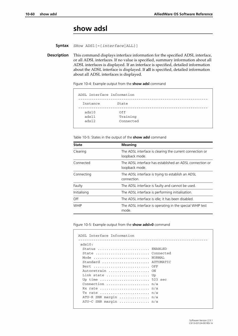
10-60 show adsl AlliedWare OS Software Reference
show adsl
Syntax SHow ADSl[={interface|ALL}]
Description This command displays interface information for the specified ADSL interface, or all ADSL interfaces. If no value is specified, summary information about all ADSL interfaces is displayed. If an interface is specified, detailed information about the ADSL interface is displayed. If all is specified, detailed information about all ADSL interfaces is displayed.
Figure 10-4: Example output from the show adsl command
Figure 10-5: Example output from the show adsl=0 command
ADSL Interface Information------------------------------------------------------------ Instance State------------------------------------------------------------ adsl0 Off adsl1 Training adsl2 Connected
Table 10-5: States in the output of the show adsl command
State Meaning
Clearing The ADSL interface is clearing the current connection or loopback mode.
Connected The ADSL interface has established an ADSL connection or loopback mode.
Connecting The ADSL interface is trying to establish an ADSL connection.
Faulty The ADSL interface is faulty and cannot be used.
Initialising The ADSL interface is performing initialisation.
Off The ADSL interface is idle; it has been disabled.
WHIP The ADSL interface is operating in the special WHIP test mode.
ADSL Interface Information------------------------------------------------------------ adsl0: Status ........................ ENABLED State ......................... Connected Mode .......................... NORMAL Standard ...................... AUTOMATIC Bert .......................... OFF Autoretrain ................... ON Link state .................... Up Up time ....................... 523 sec Connection .................... n/a Rx rate ....................... n/a Tx rate ....................... n/a ATU-R SNR margin .............. n/a ATU-C SNR margin .............. n/a
Software Version 2.9.1C613-03124-00 REV A

ATM over xDSL show adsl 10-61
Examples To display a summary of all ADSL interfaces, use the command:
sh ads
To display detailed information on ADSL interface 5, use the command:
sh ads=0
To display detailed information on all ADSL interfaces, use the command:
sh ads=all
Related Commands create atmdisable adslenable adslreset adslreset adsl counterset adslshow adsl counter
Table 10-6: Parameters in the output of the show adsl=0 command
Parameter Meaning
Status Whether or not the ADSL interface is enabled.
State The current ADSL interface state (see Table 11).
Mode The configured ADSL operating mode setting.
Standard The configured ADSL standard setting.
Bert The configured ADSL BERT setting.
Autoretrain The configured ADSL auto-retrain setting.
Link state Whether the data link is up or down.
Up time The length of time that the link has currently been up.
Signal to noise The local signal to noise margin.
Rx rate The downstream (receive) ADSL bit rate. This is the raw figure including ATM/protocol overheads.
Tx rate The upstream (transmit) ADSL bit rate. This is the raw figure including ATM/protocol overheads.
Software Version 2.9.1C613-03124-00 REV A

10-62 show adsl counter AlliedWare OS Software Reference
show adsl counter
Syntax SHow ADSl[={interface|ALL}] COUnter
where interface is the number of the ADSL interface.
Description This command displays counter information for the specified one or more ADSL interfaces.
The adsl parameter specifies which ADSL interface to show counter information about. If all is specified then counters for all ADSL interfaces are displayed.
Figure 10-6: Example output from the show adsl=0 counter command.
ADSL Interface Counter Information--------------------------------------------------------------------------- adsl0: Tx Cell ......................... 110324386 Rx Cell ......................... 110323598 Connections ..................... 1 Failed to connect ............... 0 Retrains ........................ 0 Fault recovers total ............ 0 Fault recovers current .......... 0 Last Up time .................... 0 Sec Total Up time ................... 58472 Sec Current Down time ............... 0 Sec Last Down time .................. 29 Sec Total Down time ................. 29 Sec
BERT errors ..................... 0
DMT counter info: ATU-R FEC-I ..................... 0 ATU-C FFEC-I .................... 0 ATU-R FEC-F ..................... 0 ATU-C FFEC-F .................... 0 ATU-R CRC-I ..................... 0 ATU-C FEBE-I .................... 0 ATU-R CRC-F ..................... 0 ATU-C FEBE-F .................... 0 ATU-R SEF ....................... 0 ATU-C RDI ....................... 0 ATU-R LOS ....................... 0 ATU-C LOS ....................... 0 ATU-R NCD-I ..................... 0 ATU-C FNCD-I .................... 0 ATU-R NCD-F ..................... 0 ATU-C FNCD-F .................... 0 ATU-R HEC-I ..................... 0 ATU-C FHEC-I .................... 0 ATU-R HEC-F ..................... 0 ATU-C FHEC-F .................... 0 ATU-R OCD-I ..................... 0 ATU-R OCD-F ..................... 0
Failures: Overall ......................... 0 ATU-R LOS ....................... 0 ATU-C LOS ....................... 0 ATU-R SEF ....................... 0 ATU-C RDI ....................... 0 ATU-R NCD-I ..................... 0 ATU-C FNCD-I .................... 0 ATU-R NCD-F ..................... 0 ATU-C FNCD-F .................... 0 ATU-R LCD-I ..................... 0 ATU-C FLCD-I .................... 0 ATU-R LCD-F ..................... 0 ATU-C FLCD-F .................... 0
Other: utopiaDrop ...................... 0
Software Version 2.9.1C613-03124-00 REV A

ATM over xDSL show adsl counter 10-63
Table 10-7: Parameters in the output of the show adsl=0 counter command
Parameter Meaning
Tx Cell Number of transmitted ATM cells.
Rx Cell Number of received ATM cells.
Connections Number of times the ADSL connection has been established.
Failed to Connect Number of times the ADSL connection has failed to connect.
Retrains Number of times the ADSL connection has spontaneously retrained.
Fault Recovers Total Total number of fault recovers attempted.
Fault Recovers Current Current number of fault recovers. This is automatically reset to zero when a fault is successfully recovered. If this counter reaches five recovery is abandoned.
Last Up time Time that the last (previous) link remained up.
Total Uptime Total time the link has been up (including current period if currently up).
Current Down time Time the link has currently been down (or zero if currently up).
Last Down time Length of the previous link down time.
Total Down time Total time the link has been down (including current period if currently down).
BERT errors Number of Bit Error Ratio Test errors when running in loop back mode with BERT on. N/a will be shown if the remote and local ends are out of sync.
DMT counter info
ATU-R FEC-I Count of near-end Reed-Solomon forward error correction anomalies for the interleaved data-stream.
ATU-C FFEC-I Count of far-end Reed-Solomon forward error correction anomalies for the interleaved data-stream.
ATU-R FEC-F Count of near-end CRC anomalies for the fast data stream.
ATU-C FFEC-F Count of far-end CRC anomalies for the fast data stream.
ATU-R CRC-I Count of near-end CRC anomalies for the interleaved data stream.
ATU-C FEBE-I Count of far-end CRC anomalies for the interleaved data stream.
ATU-R CRC-F Count of near-end CRC anomalies for the fast data stream
ATU-C FEBE-F Count of far-end CRC anomalies for the fast data stream
ATU-R SEF Count of near-end Severely Errored Frame defects.
ATU-C RDI Count of far-end Severely Errored Frame defects.
ATU-R LOS Count of near-end Loss of Signal defects.
ATU-C LOS Count of far-end Loss of Signal defects.
ATU-R NCD-I Count of near-end No Cell Delineation anomalies for the interleaved data stream.
ATU-C FNCD-I Count of far-end No Cell Delineation anomalies for the interleaved data stream.
Software Version 2.9.1C613-03124-00 REV A
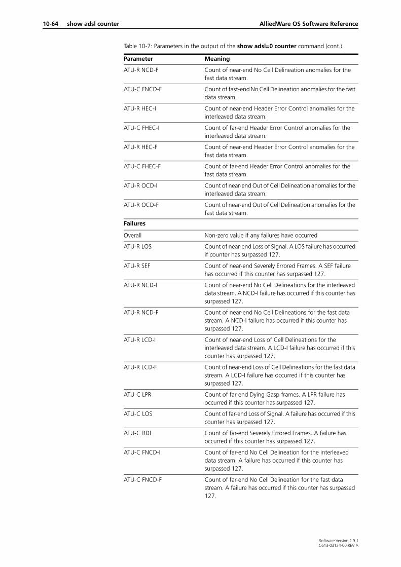
10-64 show adsl counter AlliedWare OS Software Reference
ATU-R NCD-F Count of near-end No Cell Delineation anomalies for the fast data stream.
ATU-C FNCD-F Count of fast-end No Cell Delineation anomalies for the fast data stream.
ATU-R HEC-I Count of near-end Header Error Control anomalies for the interleaved data stream.
ATU-C FHEC-I Count of far-end Header Error Control anomalies for the interleaved data stream.
ATU-R HEC-F Count of near-end Header Error Control anomalies for the fast data stream.
ATU-C FHEC-F Count of far-end Header Error Control anomalies for the fast data stream.
ATU-R OCD-I Count of near-end Out of Cell Delineation anomalies for the interleaved data stream.
ATU-R OCD-F Count of near-end Out of Cell Delineation anomalies for the fast data stream.
Failures
Overall Non-zero value if any failures have occurred
ATU-R LOS Count of near-end Loss of Signal. A LOS failure has occurred if counter has surpassed 127.
ATU-R SEF Count of near-end Severely Errored Frames. A SEF failure has occurred if this counter has surpassed 127.
ATU-R NCD-I Count of near-end No Cell Delineations for the interleaved data stream. A NCD-I failure has occurred if this counter has surpassed 127.
ATU-R NCD-F Count of near-end No Cell Delineations for the fast data stream. A NCD-I failure has occurred if this counter has surpassed 127.
ATU-R LCD-I Count of near-end Loss of Cell Delineations for the interleaved data stream. A LCD-I failure has occurred if this counter has surpassed 127.
ATU-R LCD-F Count of near-end Loss of Cell Delineations for the fast data stream. A LCD-I failure has occurred if this counter has surpassed 127.
ATU-C LPR Count of far-end Dying Gasp frames. A LPR failure has occurred if this counter has surpassed 127.
ATU-C LOS Count of far-end Loss of Signal. A failure has occurred if this counter has surpassed 127.
ATU-C RDI Count of far-end Severely Errored Frames. A failure has occurred if this counter has surpassed 127.
ATU-C FNCD-I Count of far-end No Cell Delineation for the interleaved data stream. A failure has occurred if this counter has surpassed 127.
ATU-C FNCD-F Count of far-end No Cell Delineation for the fast data stream. A failure has occurred if this counter has surpassed 127.
Table 10-7: Parameters in the output of the show adsl=0 counter command (cont.)
Parameter Meaning
Software Version 2.9.1C613-03124-00 REV A

ATM over xDSL show adsl counter 10-65
Example To show the counters for ADSL interface 0 use the command:
sh ads=0 cou
Related Commands reset adsl countershow adsl
ATU-C FLCD-I Count of far-end Loss of Cell Delineations for the interleaved data stream. A LCD-I failure has occurred if this counter has surpassed 127.
ATU-C FLCD-F Count of far-end Loss of Cell Delineations for the fast data stream. A LCD-I failure has occurred if this counter has surpassed 127.
Other
UtopiaDropped The number of cells dropped on the utopia bus in the transmit direction because of errors in timing or signalling. This is a hardware counter that indicates a possible faulty unit.
Table 10-7: Parameters in the output of the show adsl=0 counter command (cont.)
Parameter Meaning
Software Version 2.9.1C613-03124-00 REV A

10-66 show atm AlliedWare OS Software Reference
show atm
Syntax SHow ATM[=0..9]
Description This command displays information about the general ATM configuration, or the specified ATM instance.
Figure 10-7: Example output from the show atm command
ATM Module configuration----------------------------------------------------Number of instances............... 1
Table of instances------------------------------------------------------------Instance L1 interface No. VCs Status CAC------------------------------------------------------------0 adsl0 3 Up Enabled------------------------------------------------------------
Table 10-8: Parameters in the output from the show atm command
Parameter Meaning
Number of instances The number of ATM instances.
Instance The number of the ATM instance.
L1 interface The Layer 1 interface that the instance is attached to: the ADSL interface.
No. VCs The number of ATM virtual channels added to this ATM instance.
Status The status of the instance; either Up or Down.
CAC Whether Call Admission Control (CAC) is enabled or disabled on the instance.
Software Version 2.9.1C613-03124-00 REV A

ATM over xDSL show atm 10-67
Figure 10-8: Example output from the show atm=0 command
ATM instance 0-----------------------------------------------------------Status ........................ ENABLEDOver .......................... adsl0L1 Link status ................ UpL1 Link Rx rate ............... 10016 KbpsL1 Link Tx rate ............... 1024 KbpsMax Tx VC bit Rate ............ 1024 KbpsMin Tx VC bit Rate ............ 32 KbpsMax number of Channels ........ 30Number of Channels ............ 2
CAC Status ...................... Enabled Overbooking percent ......... 110 UBR booking allocation ...... 32 kbps CAC bandwidth ............... 1126 Kbps Booked Bandwidth ............ 864 kbps Available Bandwidth ......... 262 kbps
Utilisation Information Tx max data rate ............ 4173283 bps Tx current throughput ....... 0.0 bps Tx utilisation .............. 0.0 % Rx max data rate ............ 4173283 bps Rx current throughput ....... 0.0 bps Rx utilisation .............. 0.0 %
Channel Table-----------------------------------------------------------Channel Encap. VPI/VCI Status Class Description-----------------------------------------------------------
1 LLCSNAP 0/35 Enabled VBR-RT None 2 LLCSNAP 0/101 Disabled UBR UBRtoISP-----------------------------------------------------------
Table 10-9: Parameters in the output of the show atm=0 command
Parameter Meaning
Status Status of the instance
Over The Layer 1 interface that the ATM is sent over
Max bit rate The maximum bit rate that a CHANNEL can be configured to use
L1 Link status The physical layer connection link status.
L1 Link Rx rate The receive rate that the Layer 1 interface reported to ATM.
L1 Link Tx rate The transmit rate that the Layer 1 interface reported to ATM.
Max Tx VC bit Rate The maximum transmit bit rate allowed for a given channel. I.e The maximum PCR allowed.
Min Tx VC bit Rate The minimum transmit bit rate that a CHANNEL can be scheduled to use, that is, the minimum mcr or scr bit rate
Max number of Channels The maximum number of channels that can be configured on this instance.
Number of channels The number of channel's added to the instance
Software Version 2.9.1C613-03124-00 REV A

10-68 show atm AlliedWare OS Software Reference
Software Version 2.9.1
Examples To display a summary of all ATM instances, use the command:
sh atm
To display detailed information on ATM instance 0, use the command:
sh atm=0
Related Commands add atm channelcreate atmdelete atm channeldestroy atmdisable atm channelenable atm channelset atm channelshow atm channelshow atm counter
CAC
Status The status of Call Admission Control (CAC) on the instance
Overbooking percent The overbooking percentage of the interface.
UBR Booking allocation The amount of bandwidth that is used to allocate to a UBR Channel if no PCR is specified for the UBR connection.
CAC bandwidth The total bandwidth that CAC uses CAC to book channels. This includes the calculation of the overbooking percentage.
Booked bandwidth The amount of bandwidth that has been booked to existing channels.
Available bandwidth The bandwidth that has not been allocated. Note that UBR channels without a PCR will use all available bandwidth but only be booked at the UBR booking rate.
Channel Table Parameters for individual channels on the ATM instance.
Number The channel number
Encap. The channel's configured encapsulation
VPI/VCI The VCI and VPI pair for the PVC
Status The user configured status of the channel. Enabled or disabled.
Link The Link status of the Instance.
Class The traffic class of the channel
Description The user description given to the VC.
Table 10-9: Parameters in the output of the show atm=0 command (cont.)
Parameter Meaning
C613-03124-00 REV A

ATM over xDSL show atm channel 10-69
show atm channel
Syntax SHow ATM=0..9 CHANnel={1..30|ALL}
Description This command displays information about the specified ATM virtual channel, or all ATM channels.
Figure 10-9: Example output from the show atm=0 channel=1 command
ATM interface atm0.2-------------------------------------------------- Channel Number ............. 1 Channel Description ........ description of channel Channel Type ............... PVC VPI ........................ 0 VCI ........................ 102 Encapsulation .............. LLCSNAP Service Class ................. VBRRT Configured pcr ....................... 350 Kbps mcr ....................... 0 Kbps scr ....................... 200 Kbps mbs ....................... 100 Cells bt ....................... 978 Cells (calculated) Actual pcr ....................... 349 Kbps (825 cps) mcr ....................... 0 Kbps (0 cps) scr ....................... 200 Kbps (471 cps) bt ....................... 977 Cells
Utilisation Information Tx max data rate ......... 249056 bps Tx current throughput .... 115264.0 bps Tx utilisation ........... 46.28 % Rx max data rate ......... 2086641 bps Rx current throughput .... 1175687.4 bps Rx utilisation ........... 56.3 %
Attached User Modules ...... PPP IP ETH L1 interface ............... adsl0 Configured Status .......... Enabled Link Status ................ Up----------------------------------------------------
Table 10-10: Parameters in the output of the show atm=0 channel=1 command
Parameter Meaning
ATM interface The ATM instance that the virtual channel belongs to.
Channel Number The channel number
Channel Description The description of the channel
Channel Type The type of channel; PVC.
VPI The virtual path identifier.
VCI The virtual channel identifier.
Encapsulation The encapsulation, either VCMux or LLCSNAP
Software Version 2.9.1C613-03124-00 REV A

10-70 show atm channel AlliedWare OS Software Reference
Software Version 2.9.1
Examples To display detailed information about virtual channel 1 on ATM instance 0, use the command:
sh atm=0 chan=1
Related Commands add atm channelcreate atmdelete atm channeldestroy atmdisable atm channelenable atm channelset atm channelshow atmshow atm counter
Service Class Service category (serviceclass) for the channel; one of CBR, UBR, VBRRT or VBRNRT.
PCR Peak Cell Rate.
MCR Minimum Cell Rate.
SCR Sustain Cell Rate.
MBS Maximum Burst Size.
BT VBR burst tolerance. This is calculated from the pcr, scr, and mbs. The number in the parentheses is the actual rate the VC is running at. The actual BT and the requested BT may be different because some Layer 1 ports can change their rates dynamically and because of rounding factors. If the configured rate is given before the Layer 1 port (e.g., ADSL or SHDSL) is trained up, or the rate changes while up, then the parameters may change.
Tx max data rate The maximum bits per second that can be transmitted on this channel. For a VBR channel, this is:
scr + ((pcr - scr)/2)
For other channels it is pcr.
This excludes the ATM overhead, that is, it counts 48 bytes of data per cell.
Tx current throughput Current data throughput transmitted on the ATM channel.
Tx utilisation Utilisation as a percentage of the maximum bit rate for the transmit direction.
Rx max data rate The maximum bits per second that can be received on this Layer 1 interface.This excludes the ATM overhead, that is, it counts 48 bytes of data per cell.
Rx current throughput Current data throughput received on the ATM channel.
Rx utilization Utilisation as a percentage of the maximum bit rate for the receive direction.
Attached User modules Other modules (e.g. protocols) attached to this channel.
L1 Interface The layer 1 physical interface over which the ATM channel is configured.
Configured Status The user configured status of the channel; either Enabled or Disabled.
Link status The status of the instance link for this channel; either Up or Down.
Table 10-10: Parameters in the output of the show atm=0 channel=1 command (cont.)
Parameter Meaning
C613-03124-00 REV A

ATM over xDSL show atm counter 10-71
show atm counter
Syntax SHOW ATM=0..9 [CHANnel={1..30|ALL}] COUnter
Description This command displays ATM counters.
Figure 10-10: Example output from the show atm=0 counter command
Parameter Description
ATM The number of the ATM instance, in the range 0 to 9.
CHANnel The virtual channel number on the ATM instance to display counters for.
Default: No channel specific counters are displayed.
1..30 The number of the ATM virtual channel to display.
ALL All the channels on the ATM instance are displayed one after the other
ATM instance 0--------------------------------------------------UTOPIA dropped cells .......... 9CRC 10 error .................. 90Mis-inserted cells ............ 10Total packet queue length ..... 0Interface MIB Counters ifInOctets ...................... 0 ifOutOctets ..................... 0 ifInUcastPkts ................... 0 ifOutUcastPkts .................. 0 ifInErrors ...................... 0 ifOutErrors ..................... 0 ifInUnknownProtos ............... 0 ................................. ifInDiscards .................... 0 ifOutDiscards ................... 0 ifInMulticastPkts ............... 0 ifOutMulticastPkts .............. 0 ifInMulticastPkts ............... 0 ifOutMulticastPkts .............. 0 ifInBroadcastPkts ............... 0 ifOutBroadcastPkts .............. 0--------------------------------------------------
Table 10-11: Parameters in the output of the show atm=0 counter command
Parameter Meaning
Utopia dropped Cells Cells dropped due UTOPIA bus errors. This is internal communication with the PHY.
CRC 10 Errors Cells dropped due to CRC10 checksums. These are for ATM operation cells present in OAM and RM functions.
Misinserted cells This counter shows the number of cells dropped due to addressing errors. This means that either the VPI or VCI does not match any active channels or the cell is corrupted.
Out packet Queue Length The total current packet queue length of the instance’s channels.
Interface MIB Counters These are defined in RFC 2515 section 5.2.1
ifInOctets The number of received octets over the interface, i.e., the number of received, assigned cells multiplied by 53.
ifOutOctets The number of transmitted octets over the interface, i.e., the number of transmitted, assigned cells multiplied by 53.
ifInErrors The number of cells dropped due to uncorrectable HEC errors.
Software Version 2.9.1C613-03124-00 REV A

10-72 show atm counter AlliedWare OS Software Reference
Figure 10-11: Example output from the show atm=0 channel=1 counter command
ifOutErrors The number of cells packets that could not be transmitted because of errors
ifInUnknownProtos The number of received cells discarded during cell header validation, including cells with unrecognized VPI/VCI values, and cells with invalid cell header patterns.
Table 10-11: Parameters in the output of the show atm=0 counter command (cont.)
Parameter Meaning
ATM instance 0 channel 1 (atm0.1)--------------------------------------------------------------------------------Output queue length .......... 0Interface MIB Counters ifInOctets ...................... 0 ifOutOctets ..................... 0 ifInUcastPkts ................... 0 ifOutUcastPkts .................. 0 ifInErrors ...................... 0 ifOutErrors ..................... 0 ifInUnknownProtos .............. 0 ................................. ifInDiscards .................... 0 ifOutDiscards ................... 0 ifInMulticastPkts ............... 0 ifOutMulticastPkts .............. 0 ifInBroadcastPkts ............... 0 ifOutBroadcastPkts .............. 0Miscellaneous counters InCongestionSet ................. 0 InCLPSet ........................ 0 InCRCErrors ..................... 0 InAbortedPdu .................... 0 InChainedPdu .................... 0 InLengthError ................... 0 InOversizedSDU .................. 0 InLLCUnsupported ................ 0 InLLCInvalid .................... 0 ................................ 0 outFragmentDiscard .............. 0 outFrameToolong ................. 0--------------------------------------------------------------------------------
Table 10-12: Parameters in the output of the show atm=0 channel=1 counter command
Parameter Meaning
Output queue length The current packet queue length on the interface.
Interface MIB counters These are defined in RFC 2515 section 7.3
ifInOctets The number of received AAL5 CPCS PDU octets.
ifOutOctets The number of AAL5 CPCS PDU octets transmitted.
ifInUcastPkts The number of received AAL5 CPCS PDUs passed to a higher-layer.
ifOutUcastPkts The number of AAL5 CPCS PDUs received from a higher-layer for transmission. [Note: The number of AAL5 PDUs actually transmitted is the number received from a higher-layer for transmission minus any which are counted by ifOutErrors and ifOutDiscards.]
ifInErrors Number of errors in AAL5 CPCS PDUs received. The types of errors counted include CRC-32 errors, SAR time-out errors, and oversized SDU errors.
ifInUnknownProtos Always set to 0. As defined by the MIB
ifInDiscards Number of received AAL5 CPCS PDUs discarded. Possible reason may be input buffer overflow.
ifOutErrors Number of AAL5 CPCS PDUs that could not be transmitted due to errors.
Software Version 2.9.1C613-03124-00 REV A

ATM over xDSL show atm counter 10-73
Examples To display the counters for ATM instance 0, use the command:
sh atm=0 cou
Related Commands add atm channelcreate atmdelete atm channeldestroy atmdisable atm channelenable atm channelset atm channelshow atmshow atm channel
ifOutDiscards Number of AAL5 CPCS PDUs received for transmission that are discarded. Possible reason may be output buffer overflow.
ifInMulticastPkts Always set to 0. As defined by the MIB
ifInBroadcastPkts Always set to 0. As defined by the MIB
IfOutMulticastPkts Always set to 0. As defined by the MIB
IfOutBroadcastPkts Always set to 0. As defined by the MIB
InCongestionSet The number of AAL5 frames received with the congestion bit set.
InCLPSet The number of AAL5 frames received with the cell loss priority (CLP) set.
InCRCErrors The number of AAL5 frames dropped due to CRC 32 errors.
InAbortedPdu The number of AAL5 frames aborted with a zero cell.
InChainedPdu The number of AAL5 frames that were internally chained (larger than 1600 bytes)
InLengthError The number of AAL5 frames that were dropped due to ATM length reporting errors (dropped cells etc.)
InOversizedSDU The number of AAL5 frames that are over the 1600 byte internal size
InLLCUnsupported The number of AAL5 frames received that had an LLC type that is not supported
InLLCInvalid The number of AAL5 frames received with invalid or corrupt LLC headers
OutFragmentDiscard The number of Frames discarded from transmitting because they had too many fragments
OutFrameToolong The number of frames discarded from transmitting because they exceed the internal frame size limit.
Table 10-12: Parameters in the output of the show atm=0 channel=1 counter command (cont.)
Parameter Meaning
Software Version 2.9.1C613-03124-00 REV A
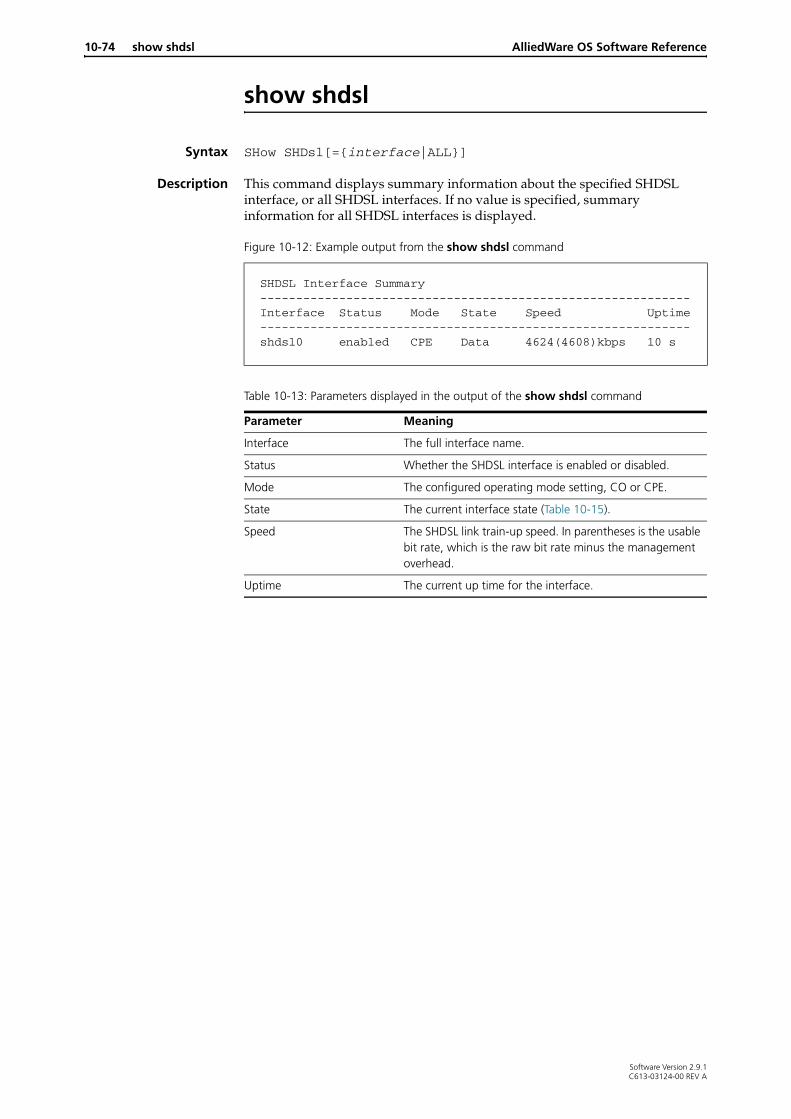
10-74 show shdsl AlliedWare OS Software Reference
show shdsl
Syntax SHow SHDsl[={interface|ALL}]
Description This command displays summary information about the specified SHDSL interface, or all SHDSL interfaces. If no value is specified, summary information for all SHDSL interfaces is displayed.
Figure 10-12: Example output from the show shdsl command
SHDSL Interface Summary------------------------------------------------------------Interface Status Mode State Speed Uptime------------------------------------------------------------ shdsl0 enabled CPE Data 4624(4608)kbps 10 s
Table 10-13: Parameters displayed in the output of the show shdsl command
Parameter Meaning
Interface The full interface name.
Status Whether the SHDSL interface is enabled or disabled.
Mode The configured operating mode setting, CO or CPE.
State The current interface state (Table 10-15).
Speed The SHDSL link train-up speed. In parentheses is the usable bit rate, which is the raw bit rate minus the management overhead.
Uptime The current up time for the interface.
Software Version 2.9.1C613-03124-00 REV A

ATM over xDSL show shdsl 10-75
Figure 10-13: Example output from the show shdsl=0 command
SHDSL Interface Information-----------------------------------------------------------shdsl0: Status ..................... Enabled Up time .................... 118 sec Link state ................. Up
Pair 1 Pair 2 ------ ------ State ...................... Data Data Last failed state .......... no_startup no_startup Speed ...................... 2312(2304) kbps 2312(2304) kbps Standard .................... Annex A Annex A
Line settings: Mode ....................... CPE Bert ....................... OFF Auto-retrain ............... ON Pair mode .................. 4WIRESTANDARD Annex standard ............. BOTH Bit rate mode .............. FIXED Minimum bit rate ........... 144 kbps Maximum bit rate ........... 4624 kbps SNR margin threshold ....... 0 dB Attenuation threshold ...... 0 dB PSD mask type .............. SYMMETRIC
Table 10-14: Parameters displayed in the output of the show shdsl=0 command
Parameter Meaning
Status Whether or not the SHDSL interface is enabled.
State The current interface state (Table 10-15).
Link State The current reported MIB operation state.
Last failed state The last state reached in the training state before start-up failed (Table 10-16 on page 10-76).
Mode The operating mode, either CO or CPE.
Speed The raw SHDSL link train-up speed. In parentheses is the usable bit rate, which is the raw bit rate minus the management overhead.
BERT The current BERT configuration.
Auto-Retrain The configuration of the Auto-Retrain feature.
Standard The configured annex standard setting.
Pair mode The current configuration of the interfaces pair mode.
Uptime The current up time for the interface
Software Version 2.9.1C613-03124-00 REV A

10-76 show shdsl AlliedWare OS Software Reference
Table 10-15: SHDSL interface states
State Meaning
Idle Waiting for commands to enable it or change configuration.
Data The connection settings were successfully negotiated and the connection is now able to send data.
Handshake Waiting for or sending handshakes from the other side.
PMMS Power Measurement Modulation Session (Line Probe). Determining the possible data rates given the line conditions.
Training Received a handshake or response from a handshake and proceeding to negotiate the connection settings.
Table 10-16: Last failed state (during training) for an SHDSL interface
Name Meaning
No Startup No reported startup failures.
Preactivation PMD pre-activation failure. Pre-activation sequence was not detected or caused an exception. C991.2 section 6.3
Activation SHDSL Activation sequence started
Check Bit rate Checking bit rates for correctness
CPE Transmit Ar Transmit handshake transaction A from HSTU-R
CO Receive Ar Receive handshake transaction A from HSTU-R
CPE Transmit Bc Transmit handshake transaction B from HSTU-C
CO Receive Bc Receive handshake transaction B from HSTU-C
CPE Transmit Ar' Retransmitting Ar
CO Wait for Ar' Waiting for retransmission of AR
CPE Transmit Bc' Retransmitting Bc
CPE Transmit Cr Transmitting the Cr Signal
CO Transmit Sc Received Cr signal responding with Sc signal
CPE Transmit Sr Transmitting the Sr signal after the Cr signal.
CO Line AGC Automatic gain control initialisation.
CPE Line AGC Automatic gain control initialisation.
FD EC Training Echo or FDM detection and calibration.
Equalizer Training Calibration of SHDSL equalizer
Tip Ring Aligned Detection and alignment of power tip and ring.
CO Transmit Tc Receiver converged and now progressing on Tc signal and waiting for the Tr signal.
CO Receive Tr Tc signal detected responding with Tr signal.
CO Transmit Fc1 Tr signal received. Sending first Fc frame.
CO Transmit Fc2 Sent first Fc frame sending second Fc frame.
CPE Receive Tc Tc signal detected responding with Tr signal.
CPE Transmit Tr Tr signal received. Waiting for FC frames.
CPE Receive Fc Received both FC frames OK.
Load cppa Loading code onto interface hardware.
Load cptrain Loading code onto interface hardware.
Software Version 2.9.1C613-03124-00 REV A

ATM over xDSL show shdsl 10-77
Examples To display summary information about SHDSL interfaces use the command:
sh shd
To display detailed information about SHDSL interface 0 use the command
sh shd=0
Related Commands disable shdslenable shdslset shdslshow shdslshow shdsl linedetailsshow shdsl counter
Load cptom Loading code onto interface hardware.
Load cpdm Loading code onto interface hardware.
Load copa Loading code onto interface hardware.
Load cotrain Loading code onto interface hardware.
Load cotom Loading code onto interface hardware.
Load codm Loading code onto interface hardware.
Load corate Loading code onto interface hardware.
Load coregfilt Loading code onto interface hardware.
Load cprate Loading code onto interface hardware.
Load cpregfilt Loading code onto interface hardware.
Table 10-16: Last failed state (during training) for an SHDSL interface (cont.)
Name Meaning
Software Version 2.9.1C613-03124-00 REV A

10-78 show shdsl counter AlliedWare OS Software Reference
show shdsl counter
Syntax SHow SHDsl={interface|ALL} COUnter
Description This command displays counter information for the specified SHDSL interface, or all SHDSL interfaces.
Figure 10-14: Example output from the show shdsl=0 counter command
SHDSL Counter Information------------------------------------------------------------shdsl0: Tx cells .................... 4417785 Rx cells .................... 12 Dropped cells ............... 0 HEC errors .................. 0 Cell deliniation ............ 01 Trains ...................... 1 Train failures .............. 0 Retrains .................... 1 Up time current ............. 2 days 23:00:32 Up time prevous ............. 01:00:10 Up time total ............... 3 days 00:00:42 Down time current ........... 00:00:00 Down time previous .......... 00:00:17 Down time total ............. 00:00:17
Local(CPE): Pair 1 Current 15 min 24 hours CRC .......... 5 0 5 SEGA ......... 6 0 6 LOSW ......... 4 0 4 CV ........... 0 0 0 ES ........... 1 0 1 SES .......... 1 0 1 UAS .......... 0 0 0
Pair 2 Current 15 min 24 hours CRC .......... 6 0 6 SEGA ......... 10 0 10 LOSW ......... 4 0 4 CV ........... 0 0 0 ES ........... 1 0 1 SES .......... 1 0 1 UAS .......... 0 0 0
Remote(CO): Pair 1 Current 15 min 24 hours CRC .......... 0 0 0 SEGA ......... 0 0 0 LOSW ......... 0 0 0 CV ........... 0 0 0 ES ........... 0 0 0 SES .......... 0 0 0 UAS .......... 0 0 0
Software Version 2.9.1C613-03124-00 REV A

ATM over xDSL show shdsl counter 10-79
Pair 2 Current 15 min 24 hours CRC .......... 0 0 0 SEGA ......... 0 0 0 LOSW ......... 0 0 0 CV ........... 0 0 0 ES ........... 0 0 0 SES .......... 0 0 0 UAS .......... 0 0 0
BERT counters Pair 1 Pair 2 ------ ------ Status .................... Enabled Enabled Sync ...................... Framed Framed BERT errors ............... 0 2 Seconds ................... 289 289
EOC counters Rx QueueDiscard ........... 0 Rx CRCError ............... 1 Rx UnknownType ............ 0 Rx InvalidAddress ......... 0 Rx ReadError .............. 0 Rx Messages ............... 2122
Tx QueueDiscard ........... 0 Tx WriteError ............. 0 Tx Messages ............... 2122
Table 10-17: Parameters displayed in the output of the show shdsl=0 counter command
Parameter Meaning
TX cells The number of cells transmitted on the line.
Rx cells The number of user cells received on the line
Dropped cells The number of ATM cells dropped by the SHDSL interface.
HEC errors The number of ATM cell errors encountered by the SHDSL interface.
Cell delineation The current state of the ATM cell delineation on the SHDSL interface. Under normal operation the value for this is always 01.
Trains The number of times the SHDSL interface has needed to train up.
Train failures The number of times the SHDSL interface has begun training an not proceeded through to the Data state.
Retrains The number of times the SHDSL interface has retrained due to line conditions.
Up time current The current length of time the interface has been in the connected state.
Up time previous The length of time the interface was in the connected state before the last loss of connection.
Up time total The length of time the interface has spent in the connected state since booting and enabling the interface.
Down time current The length of time the interface has spent out of the connected state since the interface was last connected or enabled.
Figure 10-14: Example output from the show shdsl=0 counter command (cont.)
Software Version 2.9.1C613-03124-00 REV A

10-80 show shdsl counter AlliedWare OS Software Reference
Down Time previous The length of time the interface spent out of the connected state since the last connected state.
Down time total The length of time the interface has spent out of the connected state since the interface was enabled and the device was started.
Local (CPE) and Remote (CO)
Counters for each end of the SHDSL connection. For definitions, see ITU-T Recommendation G.991.2.
CRC The number of CRC anomalies on the STU since the STU was last restarted.
SEGA The number of Segment Anomalies on the STU since the STU was last restarted.
LOSW The number of Loss of Sync Word (LOSW) Seconds on this endpoint since the STU was last restarted.
CV The number of Code Violations on the STU since the STU was last restarted.
ES The number of Errored Seconds (ES) on the STU since the STU was last restarted.
SES The number of Severely Errored Seconds (SES) on the STU since the STU was last restarted.
UAS The number of Unavailable Seconds (UAS) on the STU since the STU was last restarted.
BERT counters Bit-rate error test results for the current or most recent BERT.
Status Whether there is a BERT running:Enabled if a BERT has been startedDisabled if no BERT is running
Sync Whether the BERT has begun successfully:
Framed, if the BERT test has successfully begunNo sync, if the BERT has not successfully been able to start. This usually indicates that the remote end is not conducting a BERT.
Bert errors The number of errors for the current BERT.
Overflow, if more than 255 BERT errors have been encountered in the last second. Once the counter has overflowed, you must stop the BERT and start it again.
Seconds The number of seconds the BERT has been running for.
EOC counters Counters for the SHDSL Embedded Operation Channel (EOC).
Rx QueueDiscard The number of EOC messages that were discarded due to a full receive queue.
Rx CRCError The number of received EOC messages that were discarded due to CRC errors in the message.
Rx CRCError The number of received EOC messages that were discarded due to errors in the message detected by checking the CRC.
Rx UnknownType The number of received EOC messages that had either a corrupted second byte or a message ID that the router did not recognise.
Rx InvalidAddress The number of received EOC messages that were discarded because the destination address was neither the router address, the broadcast address nor the next hop address.
Rx ReadError The number of errors due to the software not being able to read the received EOC messages from the hardware.
Table 10-17: Parameters displayed in the output of the show shdsl=0 counter command (cont.)
Parameter Meaning
Software Version 2.9.1C613-03124-00 REV A
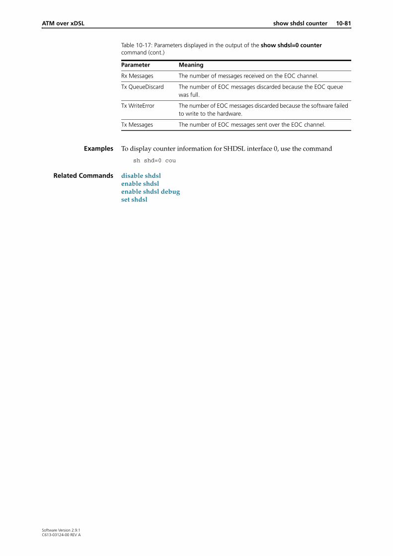
ATM over xDSL show shdsl counter 10-81
Examples To display counter information for SHDSL interface 0, use the command
sh shd=0 cou
Related Commands disable shdslenable shdslenable shdsl debugset shdsl
Rx Messages The number of messages received on the EOC channel.
Tx QueueDiscard The number of EOC messages discarded because the EOC queue was full.
Tx WriteError The number of EOC messages discarded because the software failed to write to the hardware.
Tx Messages The number of EOC messages sent over the EOC channel.
Table 10-17: Parameters displayed in the output of the show shdsl=0 counter command (cont.)
Parameter Meaning
Software Version 2.9.1C613-03124-00 REV A

10-82 show shdsl linedetails AlliedWare OS Software Reference
show shdsl linedetails
Syntax SHow SHDsl={interface|ALL} LINEdetails
Description This command displays the current negotiated configuration information for the specified SHDSL interface or all SHDSL interfaces. If the SHDSL interface is not in the data state, the parameters displayed in the output are the last received or known parameters for the connection.
Figure 10-15: Example output from the show shdsl=0 linedetails command for an SHDSL interface in data state
SHDSL Line Details-------------------------------------------------------------------------------shdsl0: Pair 1 Pair 2 ------ ------ Standard .................... Annex A Annex A Pair mode ................... 2 pair standard 2 pair standard Loop status ................. slave master Line swapped(4wire) ......... unswapped unswapped Pmms mode ................... Remote Remote Transmit power .............. 8.5 dB 8.5 dB Bit rate mode ............... Fixed Fixed Current data rate ........... 2312(2304) kbps 2312(2304) kbps Tip & ring status ........... reversed reversed Remote country code ......... United States United States Remote provider code ........ NPSG(4e505347) NPSG(4e505347) Remote encoder coeff A ...... 6e010000 6e010000 Remote encoder coeff B ...... 31030000 31030000
Signal information: Pair 1 Pair 2 ------ ------ Local(CPE): SNR ....................... 39.83 dB 40.07 dB SNR Margin ................ 17.13 dB 17.37 dB Attenuation ............... 0 dB 0 dB Remote(CO): SNR Margin ................ 18 dB 17 dB Attenuation ............... 0 dB 0 dB
Remote unit information:
Remote(CO) VendorID ......... 0x4154490000000000 (ATI.....) Remote(CO) Model ............ 0x41542d415234343253000000 (AT-AR442S...) Remote(CO) SerialNumber ..... 0x363136383134363300000000 (61681463....) Remote(CO) SoftwareVersion .. 0x332e302e3500 (3.0.5.) Remote(CO) SHDSLVersion ..... 8 Remote(CO) CLEI ............. 0x00000000000000000000 (..........) Remote(CO) VendorList ....... 0x000000 (..........) Remote(CO) VendorIssue ...... 0x0000 (..) Remote(CO) VendorOther ...... 0x322e392e312d303000000000 (2.9.1-00....)
Software Version 2.9.1C613-03124-00 REV A

ATM over xDSL show shdsl linedetails 10-83
Alarm information: Pair 1 Pair 2 ------ ------ Local(CPE): LOSW fail alarm ........... No alarm No alarm SNR Margin alarm .......... No alarm No alarm Attenuation alarm ......... No alarm No alarm Remote(CO): LOSW fail alarm ........... No alarm No alarm SNR margin alarm .......... No alarm No alarm Attenuation alarm ......... No alarm No alarm
Handshake status: Pair 1 Pair 2 ------ ------ Frame result ................ Ok Ok Message result .............. Ok Ok Session result .............. Sent ok Sent ok
Local handshake details (Pair 1):
4 Wire Support ........................... YesAnnex support ............................ A, B
TransmitSymmetric bitrates supported (kbps) ...... 64, 128, 192, 256, 320, 384 448, 512, 576, 640, 704, 768 832, 896, 960, 1024, 1088, 1152 1216, 1280, 1344, 1408, 1472, 1536 1600, 1664, 1728, 1792, 1856, 1920 1984, 2048, 2112, 2176, 2240, 2304Asymmetric support (kbps) ................ n/aSub rate support (kbps) .................. 0Power backoff (dB) ....................... n/a
ReceiveSymmetric bitrates supported (kbps) ...... 64, 128, 192, 256, 320, 384 448, 512, 576, 640, 704, 768 832, 896, 960, 1024, 1088, 1152 1216, 1280, 1344, 1408, 1472, 1536 1600, 1664, 1728, 1792, 1856, 1920 1984, 2048, 2112, 2176, 2240, 2304Asymmetric support (kbps) ................ n/aSub rate support (kbps) .................. 0Power backoff (dB) ....................... n/a
Local handshake details (Pair 2):
4 Wire Support ........................... YesAnnex support ............................ A, B
TransmitSymmetric bitrates supported (kbps) ...... 64, 128, 192, 256, 320, 384 448, 512, 576, 640, 704, 768 832, 896, 960, 1024, 1088, 1152 1216, 1280, 1344, 1408, 1472, 1536 1600, 1664, 1728, 1792, 1856, 1920 1984, 2048, 2112, 2176, 2240, 2304Asymmetric support (kbps) ................ n/aSub rate support (kbps) .................. 0Power backoff (dB) ....................... n/a
Figure 10-15: Example output from the show shdsl=0 linedetails command for an SHDSL interface in data state (cont.)
Software Version 2.9.1C613-03124-00 REV A

10-84 show shdsl linedetails AlliedWare OS Software Reference
ReceiveSymmetric bitrates supported (kbps) ...... 64, 128, 192, 256, 320, 384 448, 512, 576, 640, 704, 768 832, 896, 960, 1024, 1088, 1152 1216, 1280, 1344, 1408, 1472, 1536 1600, 1664, 1728, 1792, 1856, 1920 1984, 2048, 2112, 2176, 2240, 2304Asymmetric support (kbps) ................ n/aSub rate support (kbps) .................. 0Power backoff (dB) ....................... n/a
Remote handshake details (Pair 1):
Not master pair
Remote handshake details (Pair 2):
4 Wire Support ........................... YesAnnex support ............................ A, B
TransmitSymmetric bitrates supported (kbps) ...... 64, 128, 192, 256, 320, 384 448, 512, 576, 640, 704, 768 832, 896, 960, 1024, 1088, 1152 1216, 1280, 1344, 1408, 1472, 1536 1600, 1664, 1728, 1792, 1856, 1920 1984, 2048, 2112, 2176, 2240, 2304Asymmetric support (kbps) ................ n/aSub rate support (kbps) .................. 0Power backoff (dB) ....................... n/a
ReceiveSymmetric bitrates supported (kbps) ...... 64, 128, 192, 256, 320, 384 448, 512, 576, 640, 704, 768 832, 896, 960, 1024, 1088, 1152 1216, 1280, 1344, 1408, 1472, 1536 1600, 1664, 1728, 1792, 1856, 1920 1984, 2048, 2112, 2176, 2240, 2304Asymmetric support (kbps) ................ n/aSub rate support (kbps) .................. 0Power backoff (dB) ....................... n/a
Handshake result (Pair 1):
4 Wire Support ........................... YesAnnex support ............................ A
TransmitSymmetric bitrates supported (kbps) ...... 2304Asymmetric support (kbps) ................ n/aSub rate support (kbps) .................. 0Power backoff (dB) ....................... 6
ReceiveSymmetric bitrates supported (kbps) ...... 2304Asymmetric support (kbps) ................ n/aSub rate support (kbps) .................. 0Power backoff (dB) ....................... 6
Figure 10-15: Example output from the show shdsl=0 linedetails command for an SHDSL interface in data state (cont.)
Software Version 2.9.1C613-03124-00 REV A

ATM over xDSL show shdsl linedetails 10-85
Handshake result (Pair 2):
4 Wire Support ........................... YesAnnex support ............................ A
TransmitSymmetric bitrates supported (kbps) ...... 2304Asymmetric support (kbps) ................ n/aSub rate support (kbps) .................. 0Power backoff (dB) ....................... 6
ReceiveSymmetric bitrates supported (kbps) ...... 2304Asymmetric support (kbps) ................ n/aSub rate support (kbps) .................. 0Power backoff (dB) ....................... 6-------------------------------------------------------------------------------
Figure 10-15: Example output from the show shdsl=0 linedetails command for an SHDSL interface in data state (cont.)
Table 10-18: Parameters displayed in the output of the show shdsl=0 linedetails command
Parameter Meaning
Standard The SHDSL G.991.2 standard being used on the line; either Annex A or Annex B.
Pair Mode Whether the SHDSL line is operating in 1-pair or 2-pair mode, and if in 2-pair mode whether it is in standards-based or enhanced mode.
Loop status For standards-based 2-pair mode only, whether the pair is the master pair or the slave pair.
Line swapped Whether the pairs used in a 2-pair (4-wire) mode are swapped (pair 1 at the CPE connected to pair 2 at the CO) or unswapped.
PmmsMode Power measurement modulation session: either Local or Remote.
Transmit Power The local STU transmit power. This value is determined during training—it is not monitored.
Bit Rate Mode Indicates if the unit adapts its rate at start-up or uses a fixed rate: either Adaptive or Fixed.
Current data rate The current raw data rate that the line is operating at. In parentheses is the usable bit rate, which is the raw bit rate minus the management overhead.
Tip and ring status Whether the line polarity of the tip and ring wires is normal or reversed.
Remote country code Country code for the remote end of the SHDSL link.
Remote provider code The service provider code for the remote end of the SHDSL link.
Remote encoder coeff A Encoding coefficient A for the remote end of the SHDSL link.
Remote encoder coeff B Encoding coefficient B for the remote end of the SHDSL link.
Software Version 2.9.1C613-03124-00 REV A

10-86 show shdsl linedetails AlliedWare OS Software Reference
Signal information For Pair 1 and Pair 2.
Local (CO|CPE) SNR Local SNR calculated for the line.
Local (CO|CPE) SNR Margin The current Margin calculated to maintain 10E-7 BER.
Local (CO|CPE) Attenuation The local calculated loop attenuation.
Remote (CO|CPE) SNR margin Reported SNR margin from the remote side CPE or CO.
Remote (CO|CPE) attenuation threshold
Reported attenuation threshold.
Remote unit information
Remote (CO|CPE) VendorID Vendor ID (system integrator) as reported in an Inventory Response message.
Remote (CO|CPE) Model Vendor model number as reported in an Inventory Response message.
Remote (CO|CPE) SerialNumber
Vendor serial number as reported in an Inventory Response message.
Remote (CO|CPE) SoftwareVersion
Vendor software version as reported in an Inventory Response message.
Remote (CO|CPE) SHDSLVersion
Version of the SHDSL standard implemented, as reported in an Inventory Response message.
Remote (CO|CPE) CLEI The unique Common Language Equipment Code (CLEI), as reported in an Inventory Response message.
Remote (CO|CPE) VendorList The modem hardware version as reported in an Inventory Response message.
Remote (CO|CPE) VendorIssue The modem issue number as reported in an Inventory Response message.
Remote (CO|CPE) VendorOther Other vendor information as reported in an Inventory Response message.
Alarm information For Pair 1 and Pair 2.
Local (CO|CPE) LOSW fail alarm
The status of the local LOSW alarm; either “No alarm” or “***Alarm***”.
Local (CO|CPE) SNR Margin alarm
The status of the local SNR margin alarm; either “No alarm” or “***Alarm***”.
Local (CO|CPE) Attenuation alarm
The status of the local attenuation alarm; either “No alarm” or “***Alarm***”.
Remote (CO|CPE) LOSW fail alarm
The status of the remote LOSW alarm; either “No alarm” or “***Alarm***”.
Remote (CO|CPE) SNR Margin alarm
The status of the remote SNR margin alarm; either “No alarm” or “***Alarm***”.
Remote (CO|CPE) Attenuation alarm
The status of the remote attenuation alarm; either “No alarm” or “***Alarm***”.
Handshake status For Pair 1 and Pair 2.
Frame Result The result of frame reception during handshake.
Message Result The result of message parsing during handshake.
Session Result The result of the handshake session.
Table 10-18: Parameters displayed in the output of the show shdsl=0 linedetails command (cont.)
Parameter Meaning
Software Version 2.9.1C613-03124-00 REV A
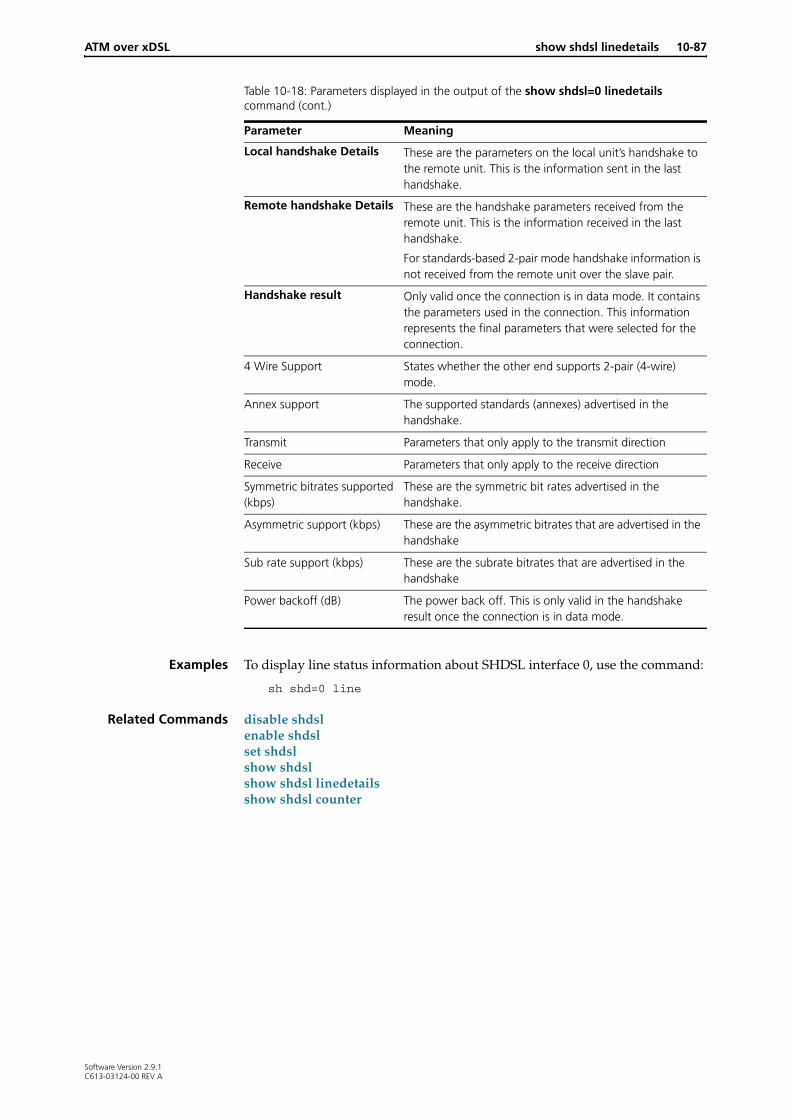
ATM over xDSL show shdsl linedetails 10-87
Examples To display line status information about SHDSL interface 0, use the command:
sh shd=0 line
Related Commands disable shdslenable shdslset shdslshow shdslshow shdsl linedetailsshow shdsl counter
Local handshake Details These are the parameters on the local unit’s handshake to the remote unit. This is the information sent in the last handshake.
Remote handshake Details These are the handshake parameters received from the remote unit. This is the information received in the last handshake.
For standards-based 2-pair mode handshake information is not received from the remote unit over the slave pair.
Handshake result Only valid once the connection is in data mode. It contains the parameters used in the connection. This information represents the final parameters that were selected for the connection.
4 Wire Support States whether the other end supports 2-pair (4-wire) mode.
Annex support The supported standards (annexes) advertised in the handshake.
Transmit Parameters that only apply to the transmit direction
Receive Parameters that only apply to the receive direction
Symmetric bitrates supported (kbps)
These are the symmetric bit rates advertised in the handshake.
Asymmetric support (kbps) These are the asymmetric bitrates that are advertised in the handshake
Sub rate support (kbps) These are the subrate bitrates that are advertised in the handshake
Power backoff (dB) The power back off. This is only valid in the handshake result once the connection is in data mode.
Table 10-18: Parameters displayed in the output of the show shdsl=0 linedetails command (cont.)
Parameter Meaning
Software Version 2.9.1C613-03124-00 REV A

10-88 show shdsl linedetails AlliedWare OS Software Reference
Software Version 2.9.1C613-03124-00 REV A