atlas engineering handbook
TRANSCRIPT

At
las
Sp
ec
ialt
y M
et
als
– T
ec
hn
ica
l Ha
nd
bo
ok
of
Ba
r P
ro
du
ct
s
The Atlas Specialty Metals
Technical Handbook
of
Bar Products
www.atlasmetals.com.au
ATLAS SPECIALTY METALSTECHNICAL SERVICES DEPARTMENT
Copyright © Atlas Specialty Metals Technical Assistance: Freecall 1800 818 599 Revised: January 2005 Email: [email protected]
www.atlasmetals.com.auTECHNICAL SERVICES 1800 818 599 Email: [email protected]
PROJECT SERVICES (03) 9272 9999 Email: [email protected]
ATLAS SPECIALTY METALS

PRINTED: JANUARY 2005 – EDITION #1
LIMITATION OF LIABILITY
The information contained in this Handbook is not intended to be an exhaustive statement of all relevant data applicable to special and general steel products. It has been designed as a guide for customers of Atlas Specialty Metals. No responsibility is implied or accepted for or in conjunction with quality or standard of any product or its suitability for any purpose or use.
It is the responsibility of the user to ensure product specified is fit for the purpose intended.
All conditions, warranties, obligations and liabilities of any kind which are or may be implied or imposed to the contrary by any statute, rule or regulation or under the general law and whether arising from the negligence of the Company, its servants or otherwise are hereby excluded except to the extent that the Company may be prevented by any statute, rule or regulation from doing so.
Published by Atlas Specialty Metals Technical Services Department
Copyright © Atlas Specialty Metals
“….you know mate, developing and innovating my products is ongoing; so is the support of my supplier” Nat Prendergast
Prendergast Fasteners Pty LtdQueensland

TABLE OF CONTENTS
1 PRODUCT PROGRAM 3
1.1 COMPANY PROFILE 5
1.2 PROCESSING SERVICES 5
1.3 TECHNICAL SERVICES 5
1.4 WEBSITE 6
1.5 FREE MACHINING CARBON STEELS 6
1.6 CARBON STEELS 7
1.7 THROUGH-HARDENING ALLOY STEELS 7
1.8 CASE-HARDENING ALLOY STEELS 8
1.9 STAINLESS STEELS 9
1.10 HOLLOW BAR 12
1.11 CAST IRON AND HYDRAULIC PRODUCTS 13
1.12 ALUMINIUM MACHINING BAR 13
2 STOCK RANGE 15
3 PROPERTIES OF STEEL GRADES COMPARED 19
3.1 CHEMICAL COMPOSITION OF THE VARIOUS STEEL GRADES 21
3.2 GRADE QUICK REFERENCE CHART 22
3.3 THE STRENGTH OF THE VARIOUS STEEL GRADES 23
3.4 STRENGTH AND TOUGHNESS 24
3.5 PROPERTIES OF CASE–HARDENING STEELS 25
4 PRODUCT DATASHEETS 27
4.1 ATLAS M1020: CARBON STEEL BRIGHT BAR 29
4.2 ATLAS M1030: CARBON STEEL BRIGHT BAR 31
4.3 ATLAS 1045: MEDIUM-TENSILE CARBON STEEL BAR 33
4.4 ATLAS 1214FM: FREE MACHINING STEEL BRIGHT CARBON BAR 36
4.5 ATLAS 12L14FM: FREE MACHINING STEEL BRIGHT CARBON BAR 38
4.6 ATLAS 4140: THROUGH–HARDENING LOW ALLOY STEEL BAR 40
4.7 ATLAS 6582: THROUGH–HARDENING LOW ALLOY STEEL BAR 43
4.8 ATLAS 4340: THROUGH–HARDENING LOW ALLOY STEEL BAR 46
4.9 ATLAS 6580: THROUGH–HARDENING LOW ALLOY STEEL BAR 49
4.10 ATLAS 8620H: CASE–HARDENING STEEL BAR 52
4.11 ATLAS 6587: CASE–HARDENING ALLOY STEEL BAR 54
4.12 ATLAS 6657: CASE–HARDENING ALLOY STEEL BAR 56
4.13 ATLAS MICRO900: HIGH-TENSILE MICRO-ALLOY STEEL BAR 58

4.14 ATLAS 303: FREE MACHINING STAINLESS STEEL BAR 60
4.15 ATLAS 304: STAINLESS STEEL BAR 63
4.16 ATLAS 316: STAINLESS STEEL BAR 65
4.17 ATLAS 420: STAINLESS STEEL BAR 68
4.18 ATLAS 431: STAINLESS STEEL BAR 70
4.19 ATLAS 2205: DUPLEX STAINLESS STEEL BAR 73
4.20 ATLAS UR52N+: DUPLEX STAINLESS STEEL BAR 75
4.21 ATLAS 2011: ALUMINIUM MACHINING BAR 77
4.22 ATLAS 6262: ALUMINIUM MACHINING BAR 80
5 NON DESTRUCTIVE TESTING OF ATLAS BAR PRODUCTS 83
5.1 HOW DOES ULTRASONIC INSPECTION WORK? 83
5.2 WHY IS ULTRASONIC INSPECTION AN ISSUE? 85
5.3 ULTRASONIC INSPECTION OF ATLAS ALLOY BAR 86
6 HEAT TREATMENT AND SURFACE TREATMENT OF STEELS 87
6.1 AS ROLLED & AS FORGED 89
6.2 ANNEALING 89
6.3 NORMALISING 89
6.4 HARDENING & TEMPERING 90
6.5 SURFACE HARDENING OF STEELS 93
6.6 CASE HARDENING – CARBURISING 93
6.7 NITRIDING 94
6.8 SELECTIVE SURFACE HARDENING 95
6.9 FLAME HARDENING 95
6.10 INDUCTION HARDENING 95
7 MACHINABILITY AND MACHINABILITY DATASHEETS 97
7.1 MACHINING AND MACHINABILITY 99
7.2 MACHINING OF CARBON AND ALLOY STEEL 100
7.3 MACHINING OF STAINLESS STEEL 110
7.4 MACHININING OF ALUMINIUM ALLOYS 124
8 TECHNICAL DATA 127
8.1 DIMENSIONAL TOLERANCES 129
8.2 METRIC – IMPERIAL CONVERSION CHART 130
8.3 HARDNESS CONVERSION TABLE 132

1. PRODUCT PROGRAM1. PRODUCT PROGRAM 2. STOCK RANGE2. STOCK RANGE


1.1 COMPANY PROFILE
Atlas Specialty Metals is synonymous with stainless and specialty metals and traces its heritage to Canada where the company began the manufacture of special metals in 1918. In 1939, Atlas Specialty Metals was established in Australia as a supplier of special metals for the Australian war effort. More than 60 years later, Atlas is an Australian owned company and still leads the way in stainless and selected specialty metals with a distribution warehousing and metal processing network that encompasses more than 20 major cities and towns across Australia and New Zealand.
1.2 PROCESSING SERVICES
Atlas branches operate automated bandsaw and hacksaw facilities offering a complete cutting service for your bar requirements. The local markets and regional centres are supported by the nearest capital city when required.
1.3 TECHNICAL SERVICES
Atlas Specialty Metals has for many years taken a leadership role in the stainless and special steels market by providing technical service support to users through our qualified and experienced staff at our distribution and processing operations.
The Atlas Specialty Metals Technical Department supports customers and sales personnel in order to:
assist with grade selection and metallurgical properties of our products assist with product selection to meet specific needs assist with the nomination and interpretation of specifications recommend fabrication procedures investigate problems when they occur and train staff and those of our customers in the use of stainless and specialty steels
The Technical Department has a fully equipped metallurgical laboratory, which is accredited by NATA for tensile testing and hardness testing. It also has facilities for conducting metallographic examinations.
The Department establishes and maintains the quality standards for product supply from mills and conducts a testing program to ensure product sold by Atlas Specialty Metals meets those standards.
Customers are invited to take advantage of the technical service provided by Atlas Specialty Metals; all enquiries can be directed to:
Freecall: 1800 818 599 Email: [email protected]
••••••
Kalgoorlie
MelbourneWodonga
Nowra
Gladstone
Mackay
Shepparton
ATLAS SPECIALTY METALS ♦ TECHNICAL HANDBOOK OF BAR PRODUCTS
5

1.4 WEBSITE
www.atlasmetals.com.au has a lot to offer, including more information about our company, products and services, however it is the quantity and quality of our technical and product information that makes our site unique. As it contains some of the information from this technical manual, we believe there is no other Australian website that contains such detailed and practical information for Engineering Products.
1.5 FREE MACHINING CARBON STEELS
1.5.1 MAIN GRADES STOCKEDAtlas 1214FMIs a low carbon free-machining steel with excellent machinability for non-critical engineering applications.
Atlas 12L14FMIs a low carbon free-machining steel with lead addition. Machinability superior to 1214FM in high-speed machining. Application in non-critical engineering applications. Cannot be welded.
1.5.2 SOME FACTS ON FREE MACHINING STEELS
Free machining steels are designed to optimise the results of machining by:
• the use of high cutting speeds and feedrates (low cycle times) • high tool life • good chip form, good chipability • high surface finish in the minimum of operations • low energy consumption • accurate dimensional control • consistency of performance.
Free machining steels are steels to which Sulphur and Phosphorus are added, hence they are called resulphurised and rephosphorised steels. The role of adding Sulphur is to create manganese sulphide inclusions which are very soft and act as an internal lubrication during the machining operation. The role of rephosphorising is to create embrittlement of the ferritic matrix in order to give rise to “micro-cracking” which improves chip breakability and dimensional stability during machining. Lead is also added to some free machining steel as lead particles in steel also act as an internal lubricant. It must be mentioned that additions of sulphur and lead have detrimental effects on hot workability, weldability, and formability. Elongated manganese sulphide inclusions also impair transverse ductility and toughness. Therefore, the use of machinability enhancers (especially sulphur) may have to be restricted for safety critical applications of engineering steels where functionality is the primary consideration.
The addition and combination of sulphur and lead in a low carbon free machining steel is very effective in reducing the cutting loads. The lead addition to free machining steels also contributes to reducing the height of the ‘built-up-edge’ on the tool while maintaining its effectiveness in protecting a high speed steel cutting edge. Leaded free-machining steels are very suitable for machining at extremely high speeds (surface speed > 400 m/min).
ATLAS SPECIALTY METALS ♦ TECHNICAL HANDBOOK OF BAR PRODUCTS
6

1.6 CARBON STEELS
1.6.1 MAIN GRADES STOCKEDAtlas M1020:All-purpose low carbon steel with good ductility and weldability. Application in non-critical engineering applications.
Atlas M1030:All-purpose medium carbon steel with intermediate strength, good ductility and weldability. Application in low-stress engineering applications.
Atlas 1045:Carbon steel for low to medium stress mechanical and automotive components. Can be heat treated by hardening and tempering (recommended for small and medium sections only) and surface-hardened.
1.6.2 SOME FACTS ON CARBON STEELS
A plain carbon steel is essentially an iron and carbon alloy which also contains minor amounts of manganese and a number of residual elements. Two relevant groups of carbon steels are low carbon steels with C-content lower than 0.30% and medium carbon steels with C-content in the range 0.30-0.60%. Low carbon steels like M1020 have essentially a ferritic micro-structure which is soft. Medium carbon steel have a ferritic-pearlitic micro-structure and have therefore higher hardness. Low carbon steels are quite tough but have low tensile strength and wear resistance. Medium carbon steels can be heat treated in order to create a martensitic structure that has a good combination of strength and toughness after tempering. The response of medium carbon steels to a quench and temper heat treatment is very limited and the depth of hardening is low. Carbon steels are successfully used where strength requirements are not too critical. For large sections, higher required material strengths and critical applications low-alloy steels would normally be suggested.
1.7 THROUGH-HARDENING ALLOY STEELS
1.7.1 MAIN GRADES STOCKEDAtlas 4140:General purpose CrMo-alloyed heat-treatable steel with high toughness, for mechanical engineering and mining applications, such as fasteners, connecting rods and pins. The grade is generally used for lighter cross-sections. It is also suitable for components for certain low-temperature applications.
Atlas 4340:CrNiMo-alloyed heat-treatable steel for highly-stressed parts in general mechanical engineering with large cross-sections and high toughness requirements, such as axles, pins, fasteners, shafts and gear components.
Atlas 6582:CrNiMo-alloyed heat-treatable steel with very high hardenability for highly-stressed parts in general mechanical engineering applications where large cross-sections and very high toughness are the requirements, such as axles, pins, fasteners, shafts and gear components.
Atlas 6580:CrNiMo-alloyed heat-treatable steel for components under high dynamic stress in mining and general engineering applications. Especially suited for medium and large cross-sections where high and uniform toughness requirements over the cross-section exist, such pinions, gear parts and drive shafts.
ATLAS SPECIALTY METALS ♦ TECHNICAL HANDBOOK OF BAR PRODUCTS
7

1.7.2 SOME FACTS ON THROUGH-HARDENING STEELS
Through-hardening steels are engineering steels that, because of their chemical composition, are suitable for hardening. They have good toughness at a given tensile strength in the quenched and tempered condition.
From the perspective of component manufacture, it is usually desirable that the steel assumes roughly the same mechanical properties over the component cross-section after heat treatment. For small sections this can be achieved with unalloyed steels (like 1045), for medium sized sections Cr-Mo steel are required (like 4140) and for very large sections only Cr-Ni-Mo can give the desired properties.
The combination of high strength and high toughness in through-hardening steels is the result of achieving a 100% martensitic structure in the steel after quenching. This structure is very hard and will be tempered by reheating the steel again to a lower temperature in order to decrease hardness and improve ductility and impact properties of the steel. The final strength and ductility of a through-hardening steel depend on the tempering temperature and time chosen. Generally through-hardening steels are tempered in the range 500 – 700°C. With a higher tempering temperature, the final strength decreases and the final ductility of the steel increases. These effects are shown in the tempering diagram for each steel grade.
A nearly 100% martensitic structure can be achieved with 4140 steels up to approximately 120mm diameter bar. For larger sections Atlas 6582, 4340 or Atlas 6580 are required to achieve a near 100% martensitic structure. It should be noted that if unalloyed steels like M1030 and 1045 are heat treated, they cannot transform into a near 100% martensitic structure. The ductility and impact properties of the retained pearlitic-ferritic micro-structure will greatly deteriorate when increasing the tensile strength of these steels by heat treatment.
Good through-hardening steels exhibit a high degree of cleanliness, particularly in regards to non-metallic inclusions and need careful balancing of chemical composition in order to react uniformly to heat treatment.
1.8 CASE-HARDENING ALLOY STEELS
1.8.1 MAIN GRADES STOCKEDAtlas 8620H:NiCrMo-alloyed case-hardening steel primarily for small components in mechanical and automotive applications where only intermediate core strength is required, such as gears, spiders and shafts.
Atlas 6587:CrNiMo-alloyed case-hardening steel for heavy-duty and highly stressed transmission components in mechanical engineering and mining applications with high demands on toughness, such as gears, pinion gears and large shafts.
Atlas 6657:NiCrMo-alloyed case-hardening steel with exceptional impact and fracture-toughness characteristics in the core. Application in mining and mechanical engineering in areas requiring resistance to high wear and high dynamic stresses.
1.8.2 SOME FACTS ON CASE–HARDENING STEELSCase-hardening steels are essentially alloy steels with low carbon content in which a high hardness in the surface zone (or “case”) is developed by altering the chemical composition of the surface zone through absorption and diffusion of carbon into the steel. This is performed during a treatment called carburising. Case hardening is the complete heat treatment which involves carburising,
8
ATLAS SPECIALTY METALS ♦ TECHNICAL HANDBOOK OF BAR PRODUCTS

holding the steel at the appropriate temperature and then quenching the steel and subsequently tempering it at a low temperature. After case hardening a component is characterised by a surface with high hardness and a relatively soft core zone which has good toughness. Typically surface hardness of 57 – 63 HRC can be achieved, whilst the carbon content in the surface layer has increased to approximately 0.7%.Case hardening of plain carbon steels is possible, but such steels have poor core strength and the application is limited to low-stressed and small components.If a component is subject to high stresses, then apart from a high surface hardness for wear resistance purpose, strength of the core is also needed. For such applications alloyed case-hardening steels are needed. Alloyed case-hardening steels have better through-hardening properties and hence as a result of the heat treatment the core areas will also be affected. In order to maintain the toughness of the core, thus avoiding the risk of brittle fracture at the higher tensile strength levels, Nickel is added as an alloying element. Nickel also contributes to retaining toughness in the surface area after carburising. Cr-Ni-Mo case-hardening steels, like Atlas 6587 and Atlas 6657, have been developed to ensure good wear resisting properties in the case whilst have high strength and toughness in the core area even in very large cross-sections.Good case-hardening steels exhibit a high degree of cleanliness, particularly in regards to non-metallic inclusions, and need careful balancing of chemical composition in order to react uniformly to heat treatment. The quality of case-hardening steels shows also in their fine-grain stability. Fine-grain stability results in low distortion of the component after the case hardening process. Good mills achieve fine-grain stability through control of aluminium and nitrogen content.
1.9 STAINLESS STEELS
1.9.1 MAIN GRADES STOCKEDAtlas 303:Atlas 303 represents the optimum in machinability among the austenitic stainless steels. It is primarily used when production involves extensive machining. Atlas 303 is generally available as a UGIMA® and new generation UGIMA®2 with machinability significantly higher than that of the standard 303.
Atlas 304:Atlas 304 is dual certified as grades 304 and 304L. Grade 304 is the standard “18/8” stainless. It has excellent forming and welding characteristics. Grade 304L, the low carbon version of 304, does not require post-weld annealing and so is extensively used in heavy gauge components. Atlas 304 is generally available as a UGIMA® and new generation UGIMA®2 with machinability significantly higher than that of the standard 304.
Atlas 316:Atlas 316 is dual certified as grades 316 and 316L. Atlas 316 is the standard molybdenum-bearing stainless steel, second in importance to 304 amongst the austenitic stainless steels. The molybdenum gives 316 better overall corrosion resistant properties than Grade 304, particularly higher resistance to pitting and crevice corrosion in chloride environments. It has excellent forming and welding characteristics. Atlas 316 is generally available as a UGIMA® and new generation UGIMA®2 with machinability significantly higher than that of the standard 316. 9
ATLAS SPECIALTY METALS ♦ TECHNICAL HANDBOOK OF BAR PRODUCTS

Atlas 420:Atlas 420 stainless steel can be hardened by quench-and-temper heat treatment. It contains a minimum of 12 per cent chromium, just sufficient to give corrosion resistance properties. It has good ductility in the annealed condition but is capable of being hardened up to Rockwell Hardness 50HRC, the highest hardness of the 12 per cent chromium grades. Like all martensitic stainless steels its best corrosion resistance is achieved when the metal is hardened and surface ground or polished. Variants of grade 420 are available with different carbon contents; these are designated as 420A, 420B, etc.Atlas 420 is generally available as a UGIMA® with machinability significantly higher than that of the standard 420.
Atlas 431:A heat treatable martensitic, nickel-bearing grade with the best corrosion resistance properties of all the martensitic grades. It has excellent tensile and torque strength, and good toughness, making it ideally suited to shafting and bolt applications. It can be hardened to approximately 40HRC. Atlas 431 is generally available as a new generation UGIMA® with machinability significantly higher than that of the standard 431.
Atlas 2205:Atlas 2205 is the most widely used duplex (ferritic/austenitic) stainless steel grade. It finds applications due to both excellent corrosion resistance and high strength, which is about double of that of the austenitic grades 304 and 316. The duplex structure also results in excellent resistance to stress corrosion cracking.
Atlas UR52N+:Atlas UR52N+ is one of a group of “super duplex” grades, combining high strength with exceptional corrosion resistance. The addition of copper to this grade gives it greatly improved resistance to strong reducing acids, particularly sulphuric acid. UR52N+ is also very highly resistant to pitting/crevice corrosion in high chloride, hot environments. Its duplex structure also results in excellent resistance to stress corrosion cracking.
Atlas 630:Atlas 630 is a precipitation-hardening steel that has a combination of high hardness and strength after suitable heat treatment. It has corrosion resistance similar to Atlas 304. Grade 630 is often referred to as 17/4 PH.
1.9.2 SOME FACTS ON STAINLESS STEELSStainless steels are iron based alloys containing a minimum of about 10.5% chromium; this forms a protective self-healing chromium-oxide film, which is the reason why this group of steels have their characteristic “stainlessness” or corrosion resistance. The ability of the oxide layer to heal itself means that the steel is corrosion resistant, no matter how much of the surface is removed. Although all stainless steels depend on the presence of chromium, other alloying elements are often added to enhance their properties. The categorisation of stainless steels is unusual amongst metals in that it is based upon the nature of their metallurgical structure.
1.9.2.1 Austenitic Stainless SteelsThis group contain at least 16% chromium and 6% nickel (the basic grade 304 is sometimes referred to as 18/8) and range through to the high alloy or “super austenitics” such as 904L and 6% molybdenum grades. Additional elements can be added such as molybdenum, titanium or copper, to modify or improve their properties, making them suitable for many critical applications involving high temperature as well as corrosion resistance. This group of steels is also suitable for cryogenic applications because the effect of the nickel content in making the steel austenitic avoids the problems of brittleness at low temperatures, which is a characteristic of other types of steel.
10
ATLAS SPECIALTY METALS ♦ TECHNICAL HANDBOOK OF BAR PRODUCTS

1.9.2.2 Ferritic Stainless SteelsThese are plain chromium (10.5 to 18%) grades such as Grade 430 and 409. Their moderate corrosion resistance and poor fabrication properties are improved in the higher alloyed grades such as 434 and 439. Resistance to stress-corrosion cracking is the most obvious advantage of the ferritic stainless steels. Ferritic steels resist chloride and caustic stress corrosion cracking very well.
1.9.2.3 Martensitic Stainless SteelsMartensitic stainless steels are also based on the addition of chromium as the major alloying element but with a higher carbon and generally lower chromium content (eg 12% in Grade 420) than the ferritic types; Grade 431 has a chromium content of about 16%, but the microstructure is still martensite despite this high chromium level because this grade also contains 2% nickel.
1.9.2.4 Duplex Stainless SteelsDuplex stainless steels such as 2205 and 2507 (these designations indicate compositions of 22% chromium, 5% nickel and 25% chromium, 7% nickel but both grades contain further minor alloying additions) have microstructures comprising a mixture of austenite and ferrite. Duplex ferritic - austenitic steels combine some of the features of each class: they are resistant to stress corrosion cracking, albeit not quite as resistant as the ferritic steels; their toughness is superior to that of the ferritic steels but inferior to that of the austenitic steels, and their strength is greater than that of the (annealed) austenitic steels, by a factor of about two. In addition the duplex steels have general corrosion resistances equal to or better than 304 and 316, and in general their pitting corrosion resistances are superior to 316. They suffer reduced toughness below about -50°C and after exposure above 300°C, so are only used between these temperatures.
1.9.2.5 Precipitation Hardening Stainless SteelsThese are chromium and nickel containing steels which can develop very high tensile strengths. The most common grade in this group is “17-4 PH”; also known as Grade 630, with the composition of 17% chromium, 4% nickel, 4% copper and 0.3% niobium. The great advantage of these steels is that they can be supplied in the “solution treated” condition; in this condition the steel is just machinable. Following machining, forming etc. the steel can be hardened by a single, fairly low temperature “ageing” heat treatment which causes no distortion of the component.
1.9.2.6 General characteristics of Stainless Steels
NOTES:1) Attraction of the steel to a magnet. Note some austenitic grades can be attracted to a magnet
if cold worked.2) Varies significantly between grades within each group. e.g. free machining grades have lower
corrosion resistances, those grades higher in molybdenum have higher resistances.3) Measured by toughness and ductility at sub-zero temperatures. Austenitic grades retain ductility to
cryogenic temperatures.
ALLOY GROUP
MagneticResponse(note 1)
Work Hardening
Rate
Corrosion Resistance
(note2)Hardenable Ductility
High Temperature Resistance
Low Temperature Resistance
(note 3)Weldability
Austenitic Generally No Very High High By Cold Work Very High Very High Very High Very High
Duplex Yes Medium Very High No Medium Low Medium High
Ferritic Yes Medium Medium No Medium High Low Low
Martensitic Yes Medium Medium Quench & Temper Low Low Low Low
Precipitation Hardening Yes Medium Medium Age
HardeningMedium to Low Low Low Low
ATLAS SPECIALTY METALS ♦ TECHNICAL HANDBOOK OF BAR PRODUCTS
11

1.10 HOLLOW BAR
1.10.1 MAIN PRODUCTS STOCKEDAtlas Carbon Steel Hollow Bar:Atlas Carbon Steel Hollow Bar is supplied in two grades. Grade 20MnVS6 (WNr 1.5217) for sizes 32-250mm and Grade St 52.0 or E355 in new nomenclature (WNr 1.0421) for all sizes 250-457mm.
20MnVS6 is a micro-alloy steel with improved mechanical properties and with controlled sulphur content to improve machinability. St52.0 is a plain carbon steel defined by specific mechanical properties. Atlas carbon steel hollow bar is an all-purpose mechanical tube suited for low and medium-stress applications.
Atlas 4140 Hollow Bar:Atlas 4140 Hollow Bar is a low-alloy through-hardening steel hollow bar, generally supplied in the hardened and tempered condition. It is used in mining and general engineering for medium and high stress applications.
Atlas 316 Hollow Bar:Atlas 316 Hollow Bar is a stainless steel Grade 316L hollow bar. It possesses good corrosion resisting properties, particularly higher resistance to pitting and crevice corrosion in chloride environments compared to grade 304. It has excellent forming and welding characteristics. Atlas 316 Hollow Bar is generally available in VALIMA® improved machinability which is produced from stainless steel 316 UGIMA® billets.
12
ATLAS SPECIALTY METALS ♦ TECHNICAL HANDBOOK OF BAR PRODUCTS

1.11 CAST IRON AND HYDRAULIC PRODUCTS
1.11.1 MAIN PRODUCTS STOCKEDAtlas Chrome Bar:Atlas Chrome Bar is a hard chromium-plated centreless ground bar supplied in Grade 1045 or in Grade 4140 heat treated. The standard 1045 Chrome Bar is supplied in the normalised condition but it is also available in an induction hardened condition.
Chrome bar is primarily used as piston rod material in all standard applications in hydraulics and pneumatics. Standard 1045 chrome bar is used for low to medium stress applications.
Chrome bar 4140 HT is used when high yield strength for medium to high stress applications is the dominant design parameter. Chrome bar 1045 induction-hardened is used when surface hardness (55-65 HRC) is the primary design criterion and lower strength of the core is acceptable.
Atlas Hydraulic Line Tube:Atlas Hydraulic Line Tube is a cold drawn seamless, low carbon steel tube supplied in the normalised condition. It is characterised by excellent weldability and formability ensuring ease of bending and flaring. Hydraulic line tube is applied in the hydraulic and pneumatic industries, as well as in general engineering.
Atlas U250 Cast Iron:Ferritic-Pearlitic flake-graphite cast iron grade. This is a cast iron product of medium hardness (180 – 220 HB) and is therefore recommended for uses where a balance is required between mechanical properties and machinability.
Atlas U300 Cast Iron:Pearlitic flake-graphite cast iron grade. This is one of the hardest qualities in flake or grey iron with hardness range 200 – 250 HB. It is therefore used when high tensile strength and/or wear-resistance is required, because of its pearlitic structure. Its surface finish is excellent because of its superior structural cohesion. This grade can be surface hardened.
Atlas U400 Cast Iron:Spheroidal-graphite ferritic cast iron grade, also referred to as ductile or “SG” cast iron. It is applied when higher strength, machinability and a good surface finish are the required characteristics. Because of its ferritic structure it is recommended for uses requiring high heat and/or electrical conductivity, as well as good magnetic permeability. It possesses high ductility and reasonable toughness.
1.12 ALUMINIUM MACHINING BAR
1.12.1 MAIN GRADES STOCKEDAtlas 2011This aluminium alloy has superior machining performance, it is especially suitable for high-speed machining. It is a short-chipping aluminium alloy due to additions of Lead and Bismuth and can be applied to minimize machining costs. It has limited corrosion resistance and anodizing properties and is generally not recommended for welding and/or brazing. Aluminium alloy 2011 has strength that is comparable to that of a mild steel.
Atlas 6262This is contemporary aluminium alloy that combines very good machinability with excellent corrosion resistance and anodizing properties. It is has good weldability and can be brazed as well. The machinability of this alloy is significantly higher than that of comparable alloys like 6061 and 6082. 13
ATLAS SPECIALTY METALS ♦ TECHNICAL HANDBOOK OF BAR PRODUCTS

1.12.2 SOME FACTS ON ALUMINIUM ALLOYS
Aluminium alloys are classified by composition using a 4 digit number, where the first digit specifies the major alloying element(s). The table below gives an overview over the different groups of aluminium alloys and their designation.
1xxx Super- or commercial-purity aluminium Non-heat-treatable 2xxx Al-Cu(-Mg) Heat-treatable 3xxx Al-Mn(-Mg) Non-heat-treatable 4xxx Al-Si Non-heat-treatable 5xxx Al-Mg Non-heat-treatable 6xxx Al-Mg-Si Heat-treatable 7xxx Al-Zn-Mg(-Cu) Heat-treatable 8xxx Other alloys
As aluminium is naturally a very soft metal, some aluminium alloys can be subjected to a heat treatment process in order to increase the final mechanical properties. This heat treatment is called precipitation hardening or age hardening: 2xxx, 6xxx and 7xxx alloys can be strengthened by precipitation hardening, or ‘ageing’. Small, finely dispersed precipitates are formed during this heat treatment, which significantly increase the strength of the alloy. Temper designations are used to indicate whether an alloy has undergone any heat treatment. Temper designations are also used to indicate whether the alloy has been subjected to cold-working after extrusion.
ATLAS SPECIALTY METALS ♦ TECHNICAL HANDBOOK OF BAR PRODUCTS
14

1. PRODUCT PROGRAM1. PRODUCT PROGRAM 2. STOCK RANGE2. STOCK RANGE


Product Section Finish Condition Size Range Metric Imperial # of Sizes
U1004 Flat CD 16.0x3.0mm – 100.0x5.0mm x x 20
M1020
Round CD/SMTP 4.76 - 152.40mm 9.52x4.76mm – x x 65
Flat CD/SMTP 152.40x25.40mm x x 40
Square CD/SMTP 25.40 - 101.60mm x x 10
M1030 Round CD/SMTP 6.0mm - 130mm x x 60
1214FM
Round CD/SMTP 4.76 - 152.40mm x x 85
Hex CD/SMTP 6.35 - 76.20mm x x 50
Square CD/SMTP 4.76 - 100.0mm x x 30
12L14FM
Round CD/SMTP 3.97mm - 90.0mm x x 60
Hex CD/SMTP 7.94 - 55.00mm x x 55
Square CD/SMTP 12.70 - 70.0mm x x 15
1045 Round BLK AR/NOR 36 - 455mm x 60
1040/1045Round SMTP AR 10 - 110mm x x 65
Round CG AR 25.40 - 130.0mm x x 15
4140
Round BLK H&T 16 - 220mm x 35
Round CD/SMTP/PLD H&T 6.35 - 450mm x x 100
Round CG H&T 12.70 - 110.0mm x x 25
Hex CD H&T 24 - 55mm x x 10
4340 Round BLK/PLD H&T 38 - 320mm x 55
Atlas 6582 Round PLD H&T 80 - 380mm x 25
Atlas 6580 Round BLK H&T 40 - 200mm x 30
Atlas 8620H Round CD/PLD ANN 35 - 90mm x 10
Atlas 6587 Round BLK/PLD ANN 50 - 360mm x 40
Atlas 6657 Round PLD ANN 30 - 185mm x 25
EN39B Round PLD ANN 90 - 200mm x 10
20MnVS6 Hollow CD/BLK AR 32x16mm - 419x319mm x 160
4140 Hollow CD/BLK H&T 45x32mm - 200x140mm x 40
316 Hollow CD/PLD ANN 32x16mm - 250x200mm x 40
303Round CD/SMTP ANN 4.76 - 63.50mm x x 40
Hex CD ANN 9.53 - 31.75mm x 15
304 Round CD/STP/PLD ANN 4.76 - 203.20mm x x 80
316 Round CD/STP/PLD ANN 4.76 - 350.0mm x x 110
316 Hex CD ANN 9.35 - 57.15mm x 35
316 Square CD ANN 6.35 - 40.0mm x x 15
431 Round CD/SMTP/CG H&T 6.35 - 116.0mm x x 35
2205 Round CD/CG ANN 12.0 - 101.60mm x x 25
Cast IronU250,U300 Hollow RM AC 60x40mm – 300x180mm x 55
Cast Iron U250, U400, U500 Round BLK AC 40-400 x 36
Chrome Bar 1045 CG/CR IND HARD 19.05 - 101.60mm x x 10
Chrome Bar 4140 CG/CR H&T 25.00 - 101.60mm x x 35
Hydraulic Line Tube Hollow ASTM A179 6.40x0.90-50.80x4.88mm x 55
Alloy 2011 Round, Hex and Square in CD/EX 10 – 200mm x x 45
Alloy 6262 Round, Hex and Square in CD/EX 10 – 120mm x 30
Finish: CD = cold drawn, SMTP = smooth turned and polished, PLD = peeled, CG = centreless ground, BLK = black, RM = rough machined, CR = hard chrome plated, EX = extruded
Condition: AR = as rolled, AC = as cast, ANN = annealed, H&T = hardened and tempered, IND HARD = induction hardened, NOR=normalised
Atlas Specialty Metals stock 1700 different bar products. The table gives an overview of the stocking program.
ATLAS SPECIALTY METALS ♦ TECHNICAL HANDBOOK OF BAR PRODUCTS
17

3. PROPERTIES OF STEEL GRADES COMPARED3. PROPERTIES OF STEEL GRADES COMPARED 4. PRODUCT DATASHEETS4. PRODUCT DATASHEETS


Product C Mn Si S P Cr Ni Mo Other
M1020 0.15-0.25 0.30-0.90 ≤ 0.35 ≤ 0.050 ≤ 0.050
M1030 0.25-0.35 0.30-0.90 ≤ 0.35 ≤ 0.050 ≤ 0.050
1045 0.43-0.50 0.30-0.90 0.10-0.35 ≤ 0.040 ≤ 0.040
1214FM ≤ 0.15 0.70-1.20 ≤ 0.10 0.24-0.40 0.04-0.12
12L14FM ≤ 0.15 0.80-1.50 ≤ 0.10 0.25-0.40 0.04-0.11 Pb: 0.15-0.35
4140 0.37-0.44 0.65-1.10 0.10-0.35 ≤ 0.040 ≤ 0.040 0.75-1.20 0.15-0.30
4340 0.37-0.44 0.55-0.90 0.10-0.35 ≤ 0.040 ≤ 0.040 0.65-0.95 1.55-2.00 0.20-0.35
6582 0.30-0.38 0.50-0.80 ≤ 0.40 ≤ 0.035 ≤ 0.035 1.30-1.70 1.30-1.70 0.15-0.30
6580 0.26-0.34 0.30-0.60 ≤ 0.40 ≤ 0.035 ≤ 0.035 1.80-2.20 1.80-2.20 0.30-0.50
8620H 0.17-0.23 0.60-0.95 0.10-0.40 ≤ 0.040 ≤ 0.040 0.35-0.70 0.35-0.75 0.15-0.25
6587 0.15-0.21 0.50-0.90 ≤ 0.40 ≤ 0.035 ≤ 0.035 1.50-1.80 1.40-1.70 0.25-0.35
6657 0.11-0.17 0.30-0.60 ≤ 0.40 ≤ 0.035 ≤ 0.035 0.80-1.10 3.00-3.50 0.10-0.25
En25 0.27-0.35 0.45-0.70 0.10-0.40 ≤ 0.040 ≤ 0.035 0.50-0.80 2.30-2.80 0.45-0.65
En26 0.36-0.44 0.45-0.70 0.10-0.40 ≤ 0.040 ≤ 0.035 0.50-0.80 2.30-2.80 0.45-0.65
En36A 0.10-0.16 0.35-0.60 ≤ 0.35 ≤ 0.040 ≤ 0.040 0.70-1.00 3.00-3.75
En39B 0.12-0.18 0.25-0.50 0.10-0.35 ≤ 0.040 ≤ 0.035 1.00-1.40 3.90-4.30 0.15-0.30
Micro900 0.35-0.40 1.20-1.50 0.50-0.70 0.04-0.07 ≤ 0.025
Al: 0.015-0.030
Ti: 0.010-0.016
V: 0.08-0.13
XP1600 0.25 1.60 2.00 Cu,Nb,Ti
Hy-Tuf 0.25 1.35 1.50 0.30 1.80 0.40
303 ≤ 0.15 ≤ 2.00 ≤ 1.00 ≥ 0.15 ≤ 0.20 17.0-19.0 8.0-10.0
304 ≤ 0.03 ≤ 2.00 ≤ 1.00 ≤ 0.030 ≤ 0.045 18.0-20.0 8.0-12.0
316 ≤ 0.03 ≤ 2.00 ≤ 1.00 ≤ 0.030 ≤ 0.045 16.0-18.0 10.0-14.0 2.0-3.0
420 ≤ 0.15 ≤ 1.00 ≤ 1.00 ≤ 0.030 ≤ 0.040 12.0-14.0
431 ≤ 0.20 ≤ 1.00 ≤ 1.00 ≤ 0.030 ≤ 0.040 15.0-17.0 1.25-2.50
329 ≤ 0.08 ≤ 1.00 ≤ 0.75 ≤ 0.030 ≤ 0.040 23.0-28.0 2.0-5.0 1.0-2.0
2205 ≤ 0.03 ≤ 2.00 ≤ 1.00 ≤ 0.020 ≤ 0.30 21.0-23.0 4.5-6.5 2.5-3.5 N: 0.08-0.20
UR52N+ ≤ 0.03 ≤ 1.50 ≤ 0.80 ≤ 0.020 ≤ 0.035 24.0-26.0 5.5-8.0 3.0-4.0Cu: 0.5-3.0
N: 0.20-0.35
3.1 CHEMICAL COMPOSITION OF THE VARIOUS STEEL GRADES
Typical composition in % of weight
ATLAS SPECIALTY METALS ♦ TECHNICAL HANDBOOK OF BAR PRODUCTS
21

3.2 GRADE QUICK REFERENCE CHART
AAAATTTT
LLLLAAAA
SSSS SSSS
PPPPEEEE
CCCCIIII AAAA
LLLLTTTT
YYYY MMMM
EEEETTTT
AAAALLLL
SSSS ����
Tec
hnic
al H
andb
ook
of B
ar P
rodu
cts
Page
22
tlt
l
3.2
G
RA
DE
QU
ICK
RE
FER
EN
CE
CH
AR
T
CM
nC
rN
iM
oO
ther
Typ
e o
f S
teel
Typ
ical
Ap
plic
atio
ns
M1
02
00.
200.
60Lo
w C
arbo
nLo
w s
tren
gth
stee
l for
non
-crit
ical
app
licat
ions
M1
03
00.
300.
60M
ediu
m C
arbo
nF
or n
on-c
ritic
al a
pplic
atio
ns w
ith h
ighe
r st
reng
th th
an M
1020
10
45
0.45
0.60
Med
ium
Car
bon
Med
ium
str
engt
h st
eel w
hich
can
be
thro
ugh
hard
ened
(sm
all s
ectio
ns)
12
14
FM≤
0.15
0.95
S =
0.3
2, P
= 0
.08
Fre
e M
achi
ning
Low
-str
engt
h bu
t hig
hly
mac
hina
ble
stee
l for
rep
etiti
on e
ngin
eerin
g
12
L14
FM≤
0.15
1.15
S =
0.3
2, P
= 0
.08,
Pb
= 0
.25
Fre
e M
achi
ning
Low
-str
engt
h st
eel s
uita
ble
for
high
-spe
ed m
achi
ning
in r
epet
ition
eng
inee
ring
envi
ronm
ent
CARBON
Mic
ro9
00
0.38
1.35
Al =
0.0
22,
Ti =
0.0
13, V
= 0
.11
Mic
ro-a
lloy
Med
ium
-hig
h st
ress
, aaaallll tttt e
eeerrrr nnnn
aaaatttt iiii v
vvv eeee tttt
oooo 1111
00004444
5555 aaaa
nnnndddd
44441111
44440000
, ver
y go
od w
elda
bilit
y an
dm
achi
nabi
lity
41
40
0.40
0.90
0.90
0.25
Thr
ough
Har
deni
ngM
ediu
m-h
igh
stre
ss in
sm
alle
r cr
oss-
sect
ions
, has
goo
d fa
tigue
pro
pert
ies
43
40
0.40
0.75
0.80
1.80
0.30
Thr
ough
Har
deni
ngP
erm
anen
t/flu
ctua
ting
stre
ss, l
arge
r cr
oss-
sect
ions
65
82
0.34
0.65
1.50
1.60
0.25
Thr
ough
Har
deni
ngP
erm
anen
t/flu
ctua
ting
stre
ss, l
arge
r cr
oss-
sect
ions
with
hig
h co
re s
tren
gth;
pppprrrr eeee
ffff eeeerrrr rrrr
eeeedddd
aaaallll tttt e
eeerrrr nnnn
aaaatttt iiii v
vvv eeee tttt
oooo 4444
33334444
0000
65
80
0.30
0.45
2.00
2.00
0.40
Thr
ough
Har
deni
ngH
ighe
st d
ynam
ic s
tres
ses,
exc
elle
nt fa
tigue
pro
pert
ies,,,,
pppprrrr eeee
ffff eeeerrrr rrrr
eeeedddd
aaaallll tttt e
eeerrrr nnnn
aaaatttt iiii v
vvv eeee tttt
ooooEEEE
nnnn2222
5555//// EEEE
nnnn2222
6666
Hy-
Tu
f0.
251.
350.
301.
800.
40S
i =
1.5
0T
hrou
gh H
arde
ning
Med
ium
str
esse
s co
mbi
ned
with
hig
h du
ctili
ty r
equi
rem
ent
En
25
0.30
0.60
0.65
2.55
0.55
Thr
ough
Har
deni
ngH
ighe
st d
ynam
ic s
tres
ses
En
26
0.40
0.60
0.65
2.55
0.55
Thr
ough
Har
deni
ngH
ighe
st d
ynam
ic s
tres
ses
86
20
H0.
200.
750.
550.
550.
20C
ase
Har
deni
ngS
mal
l dia
met
er tr
ansm
issi
on p
arts
, med
ium
-low
str
ess
expo
sure
65
87
0.18
0.65
1.65
1.55
0.30
Cas
e H
arde
ning
Tra
nsm
issi
on p
arts
sub
ject
to h
ighe
st s
tres
ses
and
wea
r co
nditi
ons
66
57
0.14
0.45
0.95
3.25
0.20
Cas
e H
arde
ning
Par
ts s
ubje
ct to
hig
hest
str
esse
s an
d w
ear
cond
ition
s, h
igh
core
str
engt
h an
d to
ughn
ess
requ
ired,
pre
ferr
ed a
ltern
ativ
e to
En3
6A, c
an re
plac
e En
39B
in c
erta
in a
pplic
atio
nsE
n3
6A
0.13
0.50
0.85
3.35
Cas
e H
arde
ning
Tra
nsm
issi
on p
arts
sub
ject
to h
ighe
st s
tres
ses
and
wea
r co
nditi
ons
En
39
B0.
150.
401.
204.
100.
20C
ase
Har
deni
ngP
arts
sub
ject
to h
ighe
st s
tres
ses,
hig
h co
re s
tren
gth
and
toug
hnes
s re
quire
d
LOW-ALLOY
XP
16
00
0.25
1.60
2.00
Cu,
Nb,
Ti
Wea
r R
esis
tant
Hig
hest
dyn
amic
str
esse
s co
mbi
ned
with
abr
asiv
e w
ear
envi
ronm
ent
30
30.
07≤
2.00
18.0
8.0
Fre
e M
achi
ning
Aus
teni
ticR
epet
ition
eng
inee
ring
for
gene
ral p
arts
man
ufac
ture
30
40.
05≤
2.00
19.0
8.0
Aus
teni
tic S
tain
less
Foo
d pr
oces
sing
, fas
tene
rs a
nd s
prin
gs
31
60.
05≤
2.00
17.0
10.0
2.0
Aus
teni
tic S
tain
less
Mor
e co
rros
ion
resi
stan
ce r
equi
red
than
304
in s
imila
r ap
plic
atio
ns
42
00.
2≤
1.00
13.0
Mar
tens
itic
Hig
h-st
reng
th c
ompo
nent
s in
flui
d ap
plic
atio
ns li
ke s
hafts
and
sle
eves
43
10.
15≤
1.00
16.0
1.9
Mar
tens
itic
Hig
h-st
reng
th s
hafts
, fas
tene
rs w
ith h
ighe
r co
rros
ion
resi
stan
ce th
an 4
20
32
90.
03≤
1.00
25.0
3.5
1.5
Dup
lex
Med
ium
str
ess
with
exc
elle
nt c
orro
sion
res
ista
nce
requ
ired
22
05
0.02
≤ 2.
0022
.05.
53.
0N
= 0
.15
Dup
lex
Med
ium
str
ess
with
exc
elle
nt c
orro
sion
res
ista
nce
requ
ired
STAINLESS
UR
52
N+
0.02
≤ 1.
5025
.06.
83.
5C
u =
1.8
, N =
0.3
0S
uper
-Dup
lex
Hig
h-st
ress
with
exc
elle
nt c
orro
sion
res
ista
nce
requ
ired
Ple
ase
no
te t
hat
th
is c
har
t g
ives
a s
um
mar
y o
nly
. Ref
er t
o t
he
ind
ivid
ual
Atl
as d
atas
hee
ts f
or
furt
her
det
ails
.
ATLAS SPECIALTY METALS ♦ TECHNICAL HANDBOOK OF BAR PRODUCTS
22
0.2% Proof Stress for various Steel Gradesindicative values for typical stock products in small and large diameter
431 Q
&T
410/
416 Q
&T
Atlas6
580 Q
&T
Atlas6
582/
4340
Q&T
4140
Q&T
1045
Q&T
1045
Blac
k
M1030
Cold
Draw
n
M1020
Cold
Draw
n
303/
304/
316/
321 A
nn
2205
Ann
ealed
UR 52N
+ Ann
ealed
1200
1000
800
600
400
200
0
MPa
min
.
40mm diam.
250mm diam.
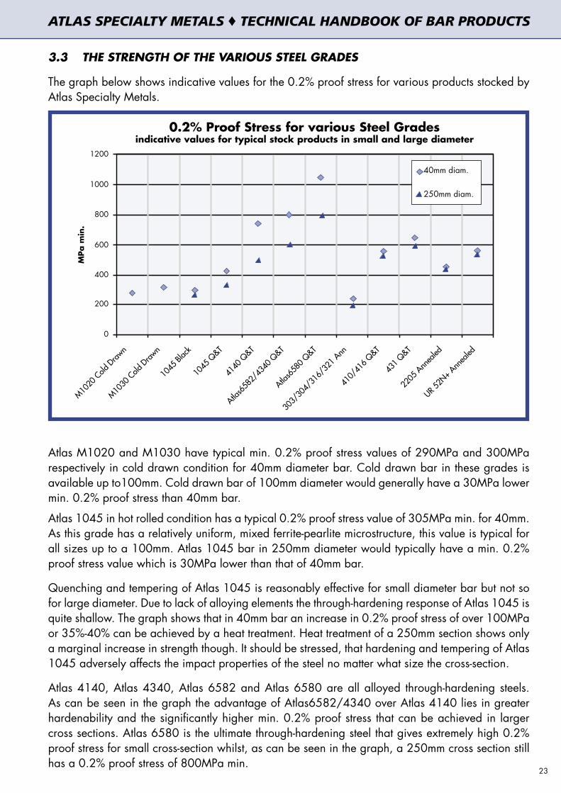
3.3 THE STRENGTH OF THE VARIOUS STEEL GRADES
The graph below shows indicative values for the 0.2% proof stress for various products stocked by Atlas Specialty Metals.
Atlas M1020 and M1030 have typical min. 0.2% proof stress values of 290MPa and 300MPa respectively in cold drawn condition for 40mm diameter bar. Cold drawn bar in these grades is available up to100mm. Cold drawn bar of 100mm diameter would generally have a 30MPa lower min. 0.2% proof stress than 40mm bar.
Atlas 1045 in hot rolled condition has a typical 0.2% proof stress value of 305MPa min. for 40mm. As this grade has a relatively uniform, mixed ferrite-pearlite microstructure, this value is typical for all sizes up to a 100mm. Atlas 1045 bar in 250mm diameter would typically have a min. 0.2% proof stress value which is 30MPa lower than that of 40mm bar.
Quenching and tempering of Atlas 1045 is reasonably effective for small diameter bar but not so for large diameter. Due to lack of alloying elements the through-hardening response of Atlas 1045 is quite shallow. The graph shows that in 40mm bar an increase in 0.2% proof stress of over 100MPa or 35%-40% can be achieved by a heat treatment. Heat treatment of a 250mm section shows only a marginal increase in strength though. It should be stressed, that hardening and tempering of Atlas 1045 adversely affects the impact properties of the steel no matter what size the cross-section.
Atlas 4140, Atlas 4340, Atlas 6582 and Atlas 6580 are all alloyed through-hardening steels. As can be seen in the graph the advantage of Atlas6582/4340 over Atlas 4140 lies in greater hardenability and the significantly higher min. 0.2% proof stress that can be achieved in larger cross sections. Atlas 6580 is the ultimate through-hardening steel that gives extremely high 0.2% proof stress for small cross-section whilst, as can be seen in the graph, a 250mm cross section still has a 0.2% proof stress of 800MPa min.
23
ATLAS SPECIALTY METALS ♦ TECHNICAL HANDBOOK OF BAR PRODUCTS

Austenitic stainless steels, like Atlas 303, 304, 316 and 321 have the lowest 0.2% proof stress of all the steels shown in the graph. The values shown in the graph are for hot rolled and/or turned product in the annealed condition. The low 0.2% proof stress should be seen in connection with the extremely high ductility of stainless steels. The tensile strength of these stainless steel products would be comparable to that of Atlas M1030.It should be noted that for all austenitic grades, annealed cold drawn bar (normally up to 25.4mm diameter) has a 0.2% proof stress that is considerably higher and typically is at 380MPa minimum, but can be significantly higher than this.Martensitic stainless steels like Atlas 410/416 and Atlas 431 have the highest strength of all stainless steels, particular Atlas 431 for which the 0.2% proof stress is almost three times as high as that of Atlas 304/316. This is particularly interesting as Atlas 431 also possesses reasonable corrosion resistance properties and good toughness. As can be seen in the graph, unlike the alloy through-hardening steels, the 0.2% proof stress of martensitic stainless steels does not drop substantially as the diameter of the cross-section increases. This is because the martensitic stainless steels have a hardenability that is exceptionally high, which is shown by the shape of the Jominy curves.If a combination of very high corrosion resistance and higher strength is required one has to revert to duplex stainless steels. Again, duplex stainless steels are very uniform in their strength regardless the diameter of the cross-section. Atlas UR52N+ is a high-strength duplex grade with a 0.2% proof stress of 530MPa min.In case a strength even higher than this is required it may be necessary to use a precipitation-hardening stainless steel such as Atlas 630, but this implies a sacrifice in corrosion resistance as compared to a duplex or a super-duplex stainless steel.
3.4 STRENGTH AND TOUGHNESS
Often and mistakenly, the tensile strength of a material is taken as the sole indication of its performance capability. A combination of strength and toughness is the true characteristic of a good steel. This is particularly true when the properties of carbon and alloy through-hardening steels are compared. Toughness is a major design criterion when semi-brittle or brittle fracture needs to be avoided.The graph below shows the minimum 0.2% proof stress and the minimum impact values for grades Atlas 1045, Atlas 4140 and Atlas 6582.It can be seen that with Atlas 1045 only limited strength levels can be achieved and the impact
Strength and Toughness:the differences for Atlas 1045, Atlas 4140 and Atlas 6582
60
55
50
45
40
35
30
25
20
min
. Ch
arp
y Im
pact
Valu
e (J
)
200 300 400 500 600 700 800 900 1000
minimum 0.2% proof stress (MPa)
values are indicativefor bars 40-100mmm
Atlas 1045
Atlas 4140
Atlas 6582
24
ATLAS SPECIALTY METALS ♦ TECHNICAL HANDBOOK OF BAR PRODUCTS

properties of this grade greatly deteriorate when hardened to higher strength. At comparable strength levels the minimum toughness of Atlas 4140 is about three times higher than that of Atlas 1045. This means that Atlas 4140 can absorb three times the impact needed to fracture Atlas 1045.The graph shows that the toughness of Atlas 4140 decreases when hardening the steel to a greater strength, but still remains at a reasonable level. If good toughness is required at higher strength levels the application of Atlas 6582 or Atlas 6580 needs to be considered. With Atlas 6582 an approximately 50% higher strength can be achieved whilst maintaining the toughness of the material.
3.5 PROPERTIES OF CASE–HARDENING STEELS
The strength and toughness of the core after case hardening are among the most important properties of engineering steels. For case-hardening steels that are applied in low stress situations the case hardness and depth of the case is the most important criterion. Once the component operates in an environment of substantial static stresses, core strength also becomes an important variable. If in addition, dynamic stresses are present, the toughness of the core then also becomes important.The core strength of a case-hardening steel depends, just like a through-hardening steel, on the hardenability of the steel as expressed in the Jominy diagram (see product datasheets contained in this handbook). After carburising of the surface layer the steel is quenched and subsequently tempered. A major difference between case-hardening steels and through-hardening steels is the tempering temperature. Case-hardening steels must be tempered at very low temperatures (150 – 200°) in order to retain the high hardness of the carburised layer achieved after quenching the steel. Because of the low carbon content in the core section, the steel maintains some ductility even at such low tempering temperatures.As for alloyed through-hardening steels, a higher alloy content is needed to ensure a deeper hardening. The following graph shows the tensile strength after the case hardening operation for Atlas 8620H, Atlas 6587 and Atlas 6657. It shows that Atlas 8620H can achieve high core strength in small cross-sections, but the core strength quickly drops off as the cross-section gets bigger. Atlas 6582 and Atlas 6657 have excellent hardenability response and can achieve high core strength at larger diameters.
If a component is applied in an environment of high dynamic stresses and has to be able to
Tensile Strength for Case Hardening Steelsin core after case hardening at various diameters
Tensile Strength (MPa)
63m
m30m
m11
mm
Atlas 6587
Atlas 6657
Atlas 8620H
Atlas 6657
Atlas 6587
Atlas 8620H
Atlas 6657
Atlas 6587
Atlas 8620H
600 700 800 900 1000 1100 1200 1300 1400 1500
25
ATLAS SPECIALTY METALS ♦ TECHNICAL HANDBOOK OF BAR PRODUCTS

withstand sudden impact and fluctuating stresses in various directions, the toughness of the steel becomes a significant parameter. The toughness of the case-hardening steel is related to the ability to withstand sudden high impact and to the level of fatigue strength.
The graph below shows the ductility of the core after the case-hardening operation for Atlas 8620H, Atlas 6587 and Atlas 6657 in various diameters. It shows that Atlas 8620H and Atlas 6657 generally have a higher ductility than Atlas 6587.
If a high core strength is required and toughness also needs to be maximised, then Atlas 6657 needs to be considered. Atlas 6657 is a tougher steel than Atlas 6587 due to its higher nickel content. The nickel content also increases the toughness of the case layer.
Elon
gatio
n (%
)
0
2
4
6
8
10
12
Atlas8620H
Atlas6587
Atlas6657
11mm
Atlas8620H
Atlas6587
Atlas6657
30mm
Atlas8620H
Atlas6587
Atlas6657
63mm
Core Ductility of Case Hardening Steelsafter case hardening for various diameters
ATLAS SPECIALTY METALS ♦ TECHNICAL HANDBOOK OF BAR PRODUCTS
26
3. PROPERTIES OF STEEL GRADES COMPARED3. PROPERTIES OF STEEL GRADES COMPARED 4. PRODUCT DATASHEETS4. PRODUCT DATASHEETS


4.1 ATLAS M1020: CARBON STEEL BRIGHT BAR
Colour Code: Yellow
4.1.1 INTRODUCTION
Atlas M1020 carbon steel bar is a merchant grade plain carbon steel bar containing nominally 0.20% carbon. Atlas M1020 has wider chemical composition limits than grade 1020. Grade M1020 is supplied based on it meeting specified chemical composition requirements only.
4.1.2 RELATED SPECIFICATIONS
Bar in grade M1020 is supplied in accordance with the requirements of AS1443 Grade M1020
4.1.3 CHEMICAL COMPOSITION
Specification values in %
C Si Mn P S
0.15-0.25 ≤ 0.35 0.30-0.90 ≤ 0.050 ≤ 0.050
4.1.4 CONDITIONS OF SUPPLY – TYPICAL MECHANICAL PROPERTIES
Atlas M1020 is not guaranteed to meet any specified minimum mechanical properties and the values in the table below reflect typical properties only. These values reflect grade D3 (AS 1443) for cold drawn sections and grade T3 (AS 1443) for turned and polished sections. Brinell Hardness (HB) limits are not specified in AS 1443.
Condition (mm) Diameter (mm) Tensile Strength (MPa)
Yield Stress (MPa)
Elongation (% in 50mm)
Hardness (HB)
Cold Drawn
Up to 16mm inclusive 480 min 380 min 12 min 142 min>16mm to 38mm inclusive 460 min 370 min 12 min 135 min>38mm to 100mm inclusive 430 min 340 min 13 min 126 min
Cold Finished / Turned and Polished
To 50mm inclusive 410 min 250 min 22 min 119 min>50mm to 250mm inclusive 410 min 230 min 22 min 119 min
M1020 can be supplied as D3 or T3 (or equivalent) with guaranteed mechanical properties on special order request.
4.1.5 CONDITIONS OF SUPPLY – FINISH, DIMENSIONS AND TOLERANCES
4.1.5.1 Surface Finish
Bright round bar up to 63.5mm diameter is all cold drawn. Bright round bars 63.5-100mm diameter are cold drawn or smooth-turned and polished. Bright round bars over 100mm diameter are all smooth-turned and polished. All hexagon bar and all square bar is cold drawn. Flat Bar is cold drawn and supplied sharp-edged or round edged.
4.1.5.2 Diameter and A/F tolerances
Round Bar: Cold drawn h10; Smooth-turned and Polished h11 or h10, Ground h8 Square Bar: h11 Hex Bar: h11 Flat Bar: h11.
4.1.5.3 Straightness – maximum deviation from a straight line
Round Bar: 1 in 1000mm
Other tolerances may be supplied for more critical applications upon enquiry.
ATLAS SPECIALTY METALS ♦ TECHNICAL HANDBOOK OF BAR PRODUCTS
29
4.1.5.4 Length Tolerance
Mill Lengths (3.5 to 6.0m): ± 250mm max.Set Lengths (3.0 to 7.0m): -0/+40mm max. tolerance is possible subject to enquiry
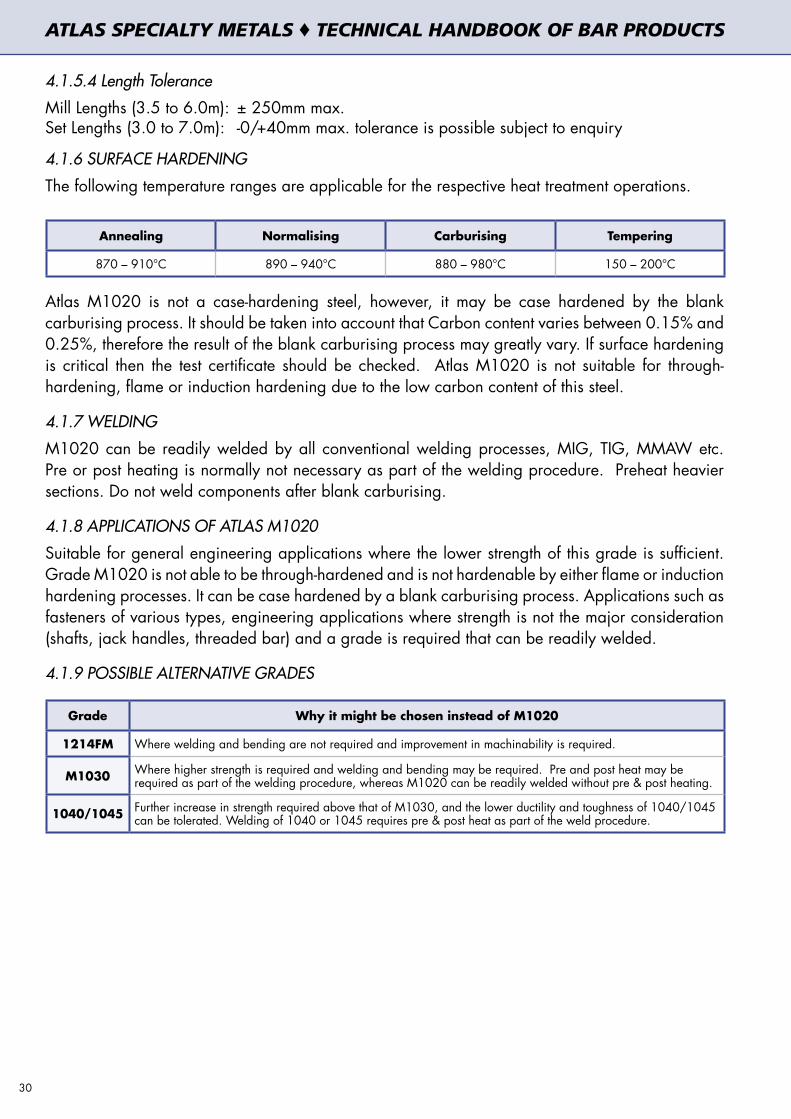
4.1.6 SURFACE HARDENING
The following temperature ranges are applicable for the respective heat treatment operations.
Annealing Normalising Carburising Tempering
870 – 910°C 890 – 940°C 880 – 980°C 150 – 200°C
Atlas M1020 is not a case-hardening steel, however, it may be case hardened by the blank carburising process. It should be taken into account that Carbon content varies between 0.15% and 0.25%, therefore the result of the blank carburising process may greatly vary. If surface hardening is critical then the test certificate should be checked. Atlas M1020 is not suitable for through-hardening, flame or induction hardening due to the low carbon content of this steel.
4.1.7 WELDING
M1020 can be readily welded by all conventional welding processes, MIG, TIG, MMAW etc. Pre or post heating is normally not necessary as part of the welding procedure. Preheat heavier sections. Do not weld components after blank carburising.
4.1.8 APPLICATIONS OF ATLAS M1020
Suitable for general engineering applications where the lower strength of this grade is sufficient. Grade M1020 is not able to be through-hardened and is not hardenable by either flame or induction hardening processes. It can be case hardened by a blank carburising process. Applications such as fasteners of various types, engineering applications where strength is not the major consideration (shafts, jack handles, threaded bar) and a grade is required that can be readily welded.
4.1.9 POSSIBLE ALTERNATIVE GRADES
Grade Why it might be chosen instead of M1020
1214FM Where welding and bending are not required and improvement in machinability is required.
M1030 Where higher strength is required and welding and bending may be required. Pre and post heat may be required as part of the welding procedure, whereas M1020 can be readily welded without pre & post heating.
1040/1045 Further increase in strength required above that of M1030, and the lower ductility and toughness of 1040/1045 can be tolerated. Welding of 1040 or 1045 requires pre & post heat as part of the weld procedure.
30
ATLAS SPECIALTY METALS ♦ TECHNICAL HANDBOOK OF BAR PRODUCTS

4.2 ATLAS M1030: CARBON STEEL BRIGHT BAR
Colour Code: White
4.2.1 INTRODUCTION
Atlas M1030 carbon bar is a merchant grade plain carbon steel product containing nominally 0.30% carbon. Atlas M1030 is supplied based on it meeting specified chemical composition requirements only.
4.2.2 RELATED SPECIFICATIONS
Bar in grade M1030 is supplied in accordance with the requirements of AS1443 Grade M1030.
4.2.3 CHEMICAL COMPOSITION
Specification values in %
C Si Mn P S
0.25-0.35 ≤ 0.35 0.30-0.90 ≤ 0.050 ≤ 0.050
4.2.4 CONDITIONS OF SUPPLY – TYPICAL MECHANICAL PROPERTIES
Atlas M1030 is not guaranteed to meet any specified minimum mechanical properties and the values in the table below reflect typical properties only. These values reflect grade D4 (AS 1443) for cold drawn sections and grade T4 (AS 1443) for turned and polished sections. Brinell Hardness (HB) limits are not specified in AS 1443.
Condition Diameter (mm) Tensile Strength (MPa)
Yield Stress (MPa)
Elongation (% in 50mm) Hardness (HB)
Cold Drawn
Up to 16mm inclusive 560 min 440 min 10 min 164 min
>16mm to 38mm inclusive 540 min 430 min 11 min 160 min
>38mm to 100mm inclusive 520 min 410 min 12 min 154 min
Hot Finished or Turned
and PolishedAll sizes to 260mm 500 min 250 min 20 min 147 min
M1030 can be supplied as D4 or T4 (or equivalent) with guaranteed mechanical properties as above on special order request.
4.2.5 CONDITIONS OF SUPPLY – FINISH, DIMENSIONS AND TOLERANCES
4.2.5.1 Surface Finish
Bright round bar up to 63.5mm diameter is all cold drawn. Bright round bars of 63.5-100mm diameter are cold drawn or smooth-turned and polished. Bright round bars over 100mm diameter are all smooth-turned and polished. All hexagonal bar and all square bar is cold drawn. Flat Bar is cold drawn and supplied sharp-edged. As rolled (black) bars available upon enquiry.
4.2.5.2 Diameter and A/F tolerances
Round Bar: Drawn h10; Smooth-turned and polished h11 or h10; Ground h8 Square Bar: h11 Hex Bar: h11 Flat Bar: h11 31
ATLAS SPECIALTY METALS ♦ TECHNICAL HANDBOOK OF BAR PRODUCTS

4.2.5.3 Straightness – maximum deviation from a straight line
Round Bar: 1 in 500mm Squares, Flats and Hexagon: 1 in 375mm
Other tolerances may be supplied for more critical applications upon enquiry.
4.2.5.4 Length Tolerance
Mill Lengths (3.5 to 6.0m): ± 250mm max. Set Lengths (3.0 to 7.0m): -0/+40mm max. tolerance is possible subject to
enquiry
4.2.6 HEAT TREATMENT
The following temperature ranges are applicable for the respective heat treatment operations.
Annealing Normalising Quenching Quenching medium Tempering
850 - 900°C 870 - 920°C 850 - 890°C Water or Brine 550 - 660°C
The tempering temperature range in the table refers to tempering after quenching. For tempering after a blank carburising process a temperature range of 150-250°C is appropriate.
4.2.7 SURFACE HARDENING
Atlas M1030 is not a dedicated case-hardening steel, nor is it a dedicated through-hardening steel. If Carbon content is below 0.30% (check test certificate) it may be case hardened by the blank carburising process, though this procedure is not generally recommended. If Carbon is above 0.30% (check test certificate) Atlas M1030 may be quenched and tempered although only a limited and shallow (up to 5mm from surface) hardening response will be achieved.
4.2.8 WELDING
M1030 can be welded by all conventional welding processes, MIG, TIG, MMAW etc. Pre and Post heating may be required as part of the welding process so as to avoid cracking, particularly in heavier sectional sizes
4.2.9 APPLICATIONS OF ATLAS M1030
Grade M1030 is used in general engineering applications. It offers an improvement in tensile strength and yield strength as compared to grade M1020 (when equivalent sectional sizes and metallurgical condition are compared). Applications such as fasteners of various types, engineering applications where strength is not the major consideration (shaft, threaded bar) and a grade is required that can be welded.
4.2.10 POSSIBLE ALTERNATIVE GRADES
Grade Why it might be chosen instead of Atlas M1030
M1020 Where a lower tensile and yield strength grade is acceptable. Pre and Post heating can not be used but would be required if M1030 is used.
1214 Where lower strength is acceptable and welding and/or bending are not required. Substantial improvement in machinability required over that offered by either grades M1030 or M1020.
1045Further increase in strength required above that of M1030 and the lower ductility and toughness of 1045 can be tolerated. Pre and post heat recommended as part of the welding procedure if grade 1045 is used and it is to be welded
32
ATLAS SPECIALTY METALS ♦ TECHNICAL HANDBOOK OF BAR PRODUCTS

4.3 ATLAS 1045: MEDIUM-TENSILE CARBON STEEL BAR
Colour Code: Jade Green
4.3.1 INTRODUCTION
Atlas 1045 is a fully killed plain carbon steel product containing nominally 0.45% carbon. This grade was formerly designated as K1045. Atlas 1045 is supplied based on it meeting specified chemical composition requirements only.
4.3.2 RELATED SPECIFICATIONS
Bar in grade 1045 is supplied in accordance with the requirements of JIS J4051 grade S45C and/or AS1442 grade 1045 in the case of black bar, and AS1443 grade 1045 in the case of bright (cold finished) bar.
4.3.3 CHEMICAL COMPOSITION
Specification values in %
C Si Mn P S
0.43-0.50 0.10 - 0.35 0.30-0.90 ≤ 0.040 ≤ 0.040
4.3.4 CONDITIONS OF SUPPLY – TYPICAL MECHANICAL PROPERTIES
Atlas 1045 is not guaranteed to meet any specified minimum mechanical properties and the values in the table below reflect typical properties only. These values reflect grade D6 (AS 1443) for cold drawn sections, grade T6 (AS 1443) for turned and polished and grade 6 (AS 1442) for rolled (black) sections. Brinell Hardness (HB) is not specified in these standards.
Condition Diameter (mm) Tensile Strength (MPa)
Yield Stress (MPa)
Elongation (% in 50mm) Hardness (HB)
Cold Drawn
Up to 16mm inclusive 690 min 540 min 8 min 207 min
>16mm to 38mm inclusive 650 min 510 min 8 min 195 min
>38mm to 80mm inclusive 640 min 500 min 9 min 190 min
As rolled/Turned and Polished All sizes to 260mm 600 min 300 min 14 min 179 min
Atlas 1045 Bright Bar can be supplied as D6 or T6 (or equivalent) with guaranteed mechanical properties on special order request. Atlas 1045 Black Bar can be supplied in the normalised condition with guaranteed mechanical properties on special order request.
4.3.5 CONDITIONS OF SUPPLY – FINISH, DIMENSIONS AND TOLERANCES
4.3.5.1 Finish
Atlas 1045 is stocked and supplied in three different surface finish classes:
as rolled/forged (black) cold drawn or smooth-turned and polished centreless ground
4.3.5.2 Diameter and A/F tolerancesAtlas 1045 black round bar is supplied with max. dimensional tolerance on diameter of ±1.5% (min. 0.4mm). Atlas 1045 cold drawn/turned round bar is supplied in tolerance h10 or h9. Atlas 1045 centreless ground round bar is supplied in tolerance h8 or better.Atlas 1045 square bar, hexagonal bar and flat bar are supplied in tolerance h11. 33
ATLAS SPECIALTY METALS ♦ TECHNICAL HANDBOOK OF BAR PRODUCTS

4.3.5.3 Straightness – maximum deviation from a straight line
As rolled (black) round bar: 3mm in 1000mmBright round bar: 2mm in 1000mmCentreless ground: 0.3mm in 1000mmSquare, flat and hexagonal bar: 1mm in 375mm
Other tolerances may be supplied for more critical applications upon enquiry.
4.3.5.4 Length Tolerance for Bright Bars
Mill Lengths (3.5 to 6.0m): ± 250mm max.Set Lengths (3.0 to 7.0m): -0/+100mm max, better tolerance subject to enquiry
4.3.6 MACHINING ALLOWANCES FOR ATLAS 1045 ROUND BAR (MM ON DIAMETER)
Bar diameter (mm)
Black (hot rolled or forged) Bright (drawn or peeled bar)
Part length <120mm Part length >120mm Part length <120mm Part length >120mm
Up to 50 incl. 2.8mm 2.8 + 6mm/m 1.0mm 1.0 + 4mm/m>50 to 100 incl. 4.5mm 4.5 + 6mm/m 1.0mm 1.0 + 4mm/m>100 to 150 incl. 5.3mm 5.3 + 6mm/m 1.0mm 1.0 + 4mm/m>150 to 200 incl. 9.0mm 9.0 + 6mm/m 1.5mm 1.5 + 4mm/m>200 to 500 incl. - - 1.5mm 1.5 + 6mm/m
Hot-rolling surface defects are retained in cold drawing. For bright bar in the range of cold drawing (up to 50mm) it is essential to take machining allowance into account. Peeled bar is generally free of surface defects. A certain allowance for surface defects is recommended however, as minor defects are permitted by the various national standards (AS, JIS, EN etc.).
4.3.7 HEAT TREATMENT
The following temperature ranges are applicable for the respective heat treatment operations.
Full Annealing Normalising Hardening Quenching medium Tempering
800 - 850°C 840 – 880°C 820 – 860°C Water or Oil 550 – 660°C
4.3.8 TYPICAL MECHANICAL PROPERTIES IN HEAT TREATED CONDITION
After quenching and tempering Atlas 1045 achieves typically the following mechanical properties.
Diameter (mm) Tensile Strength (MPa)
0.2% proof stress (MPa) Elongation (% ) Reduction of
Area (% )Impact 4.3.8.1
Charpy (J)
up to 40 incl 650 – 800 430 min 16 min 40 min 25 min>40 to 100 incl 630 – 780 370 min 17 min 45 min 25 min>100 to 250 incl 590 - 740 340 min 18 min - 22 min >250 to 500 incl 590 - 740 320 min 17 min - 20 min
34
ATLAS SPECIALTY METALS ♦ TECHNICAL HANDBOOK OF BAR PRODUCTS

4.3.10 SURFACE HARDENING
Atlas 1045 is suitable for induction hardening and flame hardening.
4.3.11 WELDING
Atlas 1045 can be welded by all conventional welding processes, MIG, TIG, MMAW etc. Pre and Post heating (also in light sections) are required as part of the welding procedure so as to avoid cracking.
4.3.12 APPLICATIONS OF ATLAS 1045
Grade 1045 is used in general engineering applications. This grade is used in engineering applications where better strength that that offered by either M1020 or M1030 is a requirement. Typical applications include hydraulic rams, shafts and medium to higher strength threaded fasteners. Atlas 1045 is generally not recommended for critical applications, particularly those where high strength is required in combination with ductility or toughness. For these application low-alloy steels are generally recommended (or in certain cases micro-alloy steels).
4.3.13 POSSIBLE ALTERNATIVE GRADES
Grade Why it might be chosen instead of 1045
M1030 Where a lower tensile and yield strength grade is acceptable. If grade M1030 is used as an alternative then pre and post heat would normally still need to be used, particularly in heavier sections.
4140
Further increase in strength required, plus guaranteed tensile properties are a requirement. Better impact properties are required. Higher core strength required. Welding of grade 4140 would not normally be recommended. In case of attempting to weld this grade guidance from an experienced and qualified welding engineer must be sought.
Roc
kw
ell H
ard
ness
(H
RC)
Hardenability of 1045Typical Jominy Test Results
10
20
30
40
50
60
max
min
distance from quenched end (mm)
0 1 2 3 4 5 6 7 8 9 10 11 13 15 20 25 30 40
4.3.9 HARDENABILITY DIAGRAM
35
ATLAS SPECIALTY METALS ♦ TECHNICAL HANDBOOK OF BAR PRODUCTS

4.4 ATLAS 1214FM: FREE MACHINING BRIGHT CARBON STEEL BAR
Colour Code: Rose Pink
4.4.1 INTRODUCTION
Atlas 1214FM is a free machining, resulphurised carbon steel bar containing nominally 0.14% carbon. Atlas 1214FM has similar chemical composition as the grade 1214. Atlas 1214FM is supplied based on it meeting specified chemical composition requirements only.
4.4.2 RELATED SPECIFICATIONS
Free machining bar Atlas 1214FM is supplied as per one of the following alternative standards.
AS1443 grade 1214,
ASTM A108 grade 1213 or grade 1215,
Euronorm EN 10087 grade 11SMn30 (1.0715) or grade 11SMn37 (1.0736).
4.4.3 CHEMICAL COMPOSITION
Specification values in %
Grade C Si Mn P S
AS 1214 ≤ 0.15 ≤ 0.10 0.80–1.20 0.04–0.09 0.25–0.35
ASTM 1213 ≤ 0.13 -- 0.70–1.00 0.07–0.12 0.24–0.33
ASTM 1215 ≤ 0.09 -- 0.75–1.05 0.07–0.12 0.26–0.35
11SMn30 ≤ 0.14 ≤ 0.05 0.90-1.30 ≤ 0.11 0.27-0.33
11SMn37 ≤ 0.14 ≤ 0.05 1.00-1.50 ≤ 0.11 0.34-0.40
The grades are characterised by high and consistent machinability and the ability to be electroplated. Grades can be interchanged without problems and no marked changes are to be expected by the user. Grade 11SMn37 has the highest machinability of these alternatives.
4.4.4 CONDITIONS OF SUPPLY – TYPICAL MECHANICAL PROPERTIES
Atlas 1214FM is not tensile tested therefore it is not guaranteed to meet any specified minimum tensile property requirements. The mechanical properties stated below (except HB values) are specified in AS1443 grade D12 (cold drawn) and AS1443 grade T12 (peeled and polished). Grades D12 and T12 are grade 1214 with guaranteed mechanical properties.
Condition Diameter (mm) Tensile Strength (MPa)
Yield Stress (MPa)
Elongation (% in 50mm)
Hardness (HB)
Cold Drawn
Up to 16mm inclusive 480 min 350 min 7 min 142 – 226
>16mm to 38mm inclusive 430 min 330 min 8 min 126 – 210
>38mm to 100mm inclusive 400 min 290 min 9 min 119 – 200
Cold Finished/Turned and polished
To 260mm inclusive 370 min 230 min 17 min 105 - 154
Atlas 1214FM can be supplied with guaranteed mechanical properties on special order request.
36
ATLAS SPECIALTY METALS ♦ TECHNICAL HANDBOOK OF BAR PRODUCTS

4.4.5 CONDITIONS OF SUPPLY – FINISH, DIMENSIONS AND TOLERANCES
4.4.5.1 Surface Finish
Bright round bar up to 63.5mm diameter is all cold drawn. Bright round bars 63.5-100mm diameter are cold drawn or smooth-turned and polished. Bright round bars over 100mm diameter are all smooth-turned and polished.
All hexagon bar and all square bar is cold drawn. Flat Bar is cold drawn and supplied sharp-edged.
4.4.5.2 Diameter and A/F tolerances
Round Bar: Drawn h10; Smooth-turned and polished h11 or h10; Square Bar: h11; Hex Bar; h11; Flat Bar: h11.
4.4.5.3 Straightness – maximum deviation from a straight line
Round Bar: 1 in 1000mmSquares, Flats and Hexagon: 1 in 375mm
Other tolerances may be supplied for more critical applications upon enquiry.
4.4.5.4 Length Tolerance Bright Bar
Mill Lengths (3.5 to 6.0m): ± 250mm max.Set Lengths (3.0 to 7.0m): -0/+40mm max. tolerance is possible subject to enquiry
4.4.6 WELDING
Atlas 1214 can be welded by all conventional welding processes, MIG, TIG, MMAW etc, however this grade is rich in manganese sulphide inclusions and when welded a low strength poor quality weld normally results. Unless such a weld can be tolerated in the intended application, then welding of this grade should not be attempted.
4.4.7 APPLICATIONS OF ATLAS 1214FM
General repetition engineering applications where the lower strength and ductility are acceptable. Atlas 1214FM cannot be through hardened and is not hardenable by either flame or induction hardening processes. It can be case hardened by a blank carburising process. Typical applications are domestic bin axles, concrete anchors, padlock shackles (case hardened), hydraulic fittings. 1214FM has low ductility, so it is unsuitable for applications requiring extensive bending or forming.
4.4.8 POSSIBLE ALTERNATIVE GRADES
Grade Why it might be chosen instead of 1214FM
12L14FM12L14FM might be used where better tool life and a slight improvement in machinability over that of grade 1214FM is a requirement.
M1020Where welding and/or bending are required and machinability is a secondary requirement. Also where the finally machined components are to be electroplated and a better quality plated finish is a requirement. Where higher ductility is needed than offered by 1214FM because of significant bending or forming operations.
M1030Where higher strength is required and welding and bending may be required. Pre and post heat may be required as part of the welding procedure for M1030.
37
ATLAS SPECIALTY METALS ♦ TECHNICAL HANDBOOK OF BAR PRODUCTS

4.5 ATLAS 12L14FM: FREE MACHINING STEEL BRIGHT CARBON BAR
Colour Code: Violet
4.5.1 INTRODUCTION
Atlas 12L14FM is a free machining carbon steel bar containing maximum 0.15% Carbon. Due to the addition of Lead (Pb) this grade has the highest machinability and is suitable for high-volume ultra-high speed machining.
4.5.2 RELATED SPECIFICATIONS
Free machining bar Atlas 12L14FM is supplied as per the following alternative standards.
AS1443 grade 12L14, ASTM A108 grade 12L14, Euronorm EN 10087 grade 11SMnPb37 (1.0737).
4.5.3 CHEMICAL COMPOSITION
Specification values in %
Grade C Si Mn P S Pb
12L14 ≤ 0.15 ≤ 0.10 0.80–1.20 0.04–0.09 0.25–0.35 0.15-0.35
11SMnPb37 ≤ 0.14 ≤ 0.05 1.00-1.50 ≤ 0.11 0.34-0.40 0.20-0.35
The grades are equally characterised by very high and consistent machinability and the ability to be electroplated. Grades can be interchanged without problems and no marked changes in machinability are to be expected.
4.5.4 CONDITIONS OF SUPPLY – TYPICAL MECHANICAL PROPERTIES
Atlas 12L14FM is not guaranteed to meet any specified minimum tensile property requirements. The values in the table below reflect typical properties only. These mechanical properties (except for HB values) are specified in AS1443 grade D13 (cold drawn) and AS1443 grade T13 (peeled and polished). Grades D13 and T13 are essentially grade 12L14FM with guaranteed mechanical properties.
Condition Diameter (mm) Tensile Strength (MPa)
Yield Stress (MPa)
Elongation (% in 50mm)
Hardness (HB)
Cold Drawn
Up to 16mm inclusive 480 min 350 min 7 min 142 – 226
>16mm to 38mm inclusive 430 min 330 min 8 min 126 – 210
>38mm to 100mm inclusive 400 min 290 min 9 min 119 – 200
Cold Finished/Turned and polished To 260mm inclusive 370 min 230 min 17 min 105 - 154
Atlas 12L14FM can be supplied with guaranteed mechanical properties on special order request.
4.5.5 CONDITIONS OF SUPPLY – FINISH, DIMENSIONS AND TOLERANCES
4.5.5.1 Surface Finish
Bright round bar up to 63.5mm diameter is all cold drawn. Bright round bars of 63.5-100mm diameter are cold drawn or smooth-turned and polished. Bright round bars over 100mm diameter are all smooth-turned and polished.All hexagon bar and all square bar is cold drawn. Flat Bar is cold drawn and supplied sharp-edged.
••
38
ATLAS SPECIALTY METALS ♦ TECHNICAL HANDBOOK OF BAR PRODUCTS

4.5.5.2 Diameter and A/F tolerances Round Bar: Drawn h10; Smooth-turned and polished h10 or h11; Square Bar: h11; Hex Bar: h11; Flat Bar: h11.
4.5.5.3 Straightness – maximum deviation from a straight lineRound Bar: 1 in 1000mmSquares, Flats and Hexagon: 1 in 375mm
Other tolerances may be supplied for more critical applications upon enquiry.
4.5.5.4 Length ToleranceMill Lengths (3.5 to 6.0m): ± 250mm max.Set Lengths (3.0 to 7.0m): -0/+40mm max. tolerance is possible subject to enquiry
4.5.6 WELDINGAtlas 12L14FM is not suitable for any welding. Lead fumes originating during the welding operation constitute a health hazard.
4.5.7 APPLICATIONS OF ATLAS 12L14FM
General repetition engineering applications where the lower strength of this product is acceptable. Atlas 12L14FM is not capable of being through hardened and is not hardenable by either flame or induction hardening processes. It can be case hardened by a blank carburising process. Applications such as domestic bin axles, concrete anchors, padlock shackles (case hardened), hydraulic fittings, vice jaws (case hardened). Ductility of Atlas 12L14FM is low, so it is not suitable for applications requiring significant bending or forming.
4.5.8 POSSIBLE ALTERNATIVE GRADES
Grade Why it might be chosen instead of Atlas 12L14FM
Atlas 1214FM
Slightly lower machinability than 12L14FM. Recommended in case the use of leaded steels is a factor of concern, such as in welding or general environmental concern.
M1020Where welding is required and machinability is a secondary requirement. Also where the finally machined components are to be electroplated and a better quality plated finish is a requirement. Where higher ductility is required because of significant bending and forming.
M1030 Where higher strength is required and welding and bending may be required. Pre and post heat may be required as part of the welding procedure, whereas M1020 is readily welded without pre & post heating.
39
ATLAS SPECIALTY METALS ♦ TECHNICAL HANDBOOK OF BAR PRODUCTS

4.6 ATLAS 4140: THROUGH-HARDENING LOW ALLOY STEEL BAR
Colour Coding: Jade (band) - Bluebell
4.6.1 INTRODUCTIONAtlas 4140 is a Chromium-Molybdenum through-hardening steel of medium hardenability. It is a general purpose high-tensile steel with medium strength level and good impact properties.
4.6.2 RELATED SPECIFICATIONSMaterial stocked by Atlas complies with grade AS1444 Grade 4140 and/or ASTM A434 (A29) Grade 4140 and/or Euronorm EN 10083 grade 42CrMo4 (Material Number 1.7225/17227).
4.6.3 CHEMICAL COMPOSITION
Specification values in %
C Si Mn P S Cr Mo Ni
0.37-0.44 0.10-0.35 0.65-1.10 ≤ 0.040 ≤ 0.040 0.75-1.20 0.15-0.30 --
4.6.4 CONDITIONS OF SUPPLY – MECHANICAL PROPERTIES Atlas 4140 is supplied in the hardened and tempered condition. The level of hardness is selected to give useful strength while still maintaining the ability to machine the material into finished components.
Diameter (mm)
Heat Treated Condition
Tensile Strength (MPa)
0.2% proof stress (MPa)
Elongation (% in
50mm)
Impact Izod (J) or Charpy (J)
Hardness (HB)
up to 180 incl AS1444 Condition U 930 – 1080 740 min 12 min 47 min 42 min 269 - 331>180 to 250 incl AS1444 Condition T 850 – 1000 665 min 13 min 54 min 50 min 248 – 302>250 to 450 incl AS1444 Condition T 850 – 1000 665 min 13 min not guaranteed 248 – 302
Atlas 4140 can be re-heat-treated to higher strength or tempered back to lower strength levels than those supplied as standard. Assistance with heat treatment should be sought from reputable heat treatment companies
4.6.5 CONDITIONS OF SUPPLY – SURFACE FINISH AND MACHINING ALLOWANCEAtlas 4140 Black is supplied with +/– tolerances according to DIN 1013 or better. Atlas 4140 Bright is supplied cold drawn with h10 tolerance for bar diameters up to 25mm; bars with diameters 25 to 75mm are supplied as cold drawn with h10 tolerance or peeled with k12 tolerance, diameters 75-220mm are supplied peeled to k12, sizes over 210mm are supplied peeled to -0/+2mm.
4.6.6 MACHINING ALLOWANCES FOR ATLAS 4140 ROUND BAR (MM ON DIAMETER)
Bar diameter (mm)Black (hot rolled or forged) Bright (drawn or peeled bar)
part length <120mm part length >120mm part length <120mm part length >120mm
0-50 1.5mm 1.5 + 6mm/m 1.0mm 1.0 + 4mm/m
50-100 2.3mm 2.3 + 6mm/m 1.0mm 1.0 + 4mm/m
100-150 4.5mm 4.5 + 6mm/m 1.0mm 1.0 + 4mm/m
150-210 6.5mm 6.5 + 6mm/m 1.5mm 1.5 + 4mm/m
210-450 - - 1.5mm 1.5 + 6mm/m
Hot-rolling surface defects are retained in cold drawing. For bright bar in the range of cold drawing (up to 50mm) it is essential to take machining allowance into account. Peeled bar is generally free of surface defects. A certain allowance for surface defects is recommended however, as minor defects are permitted by the various national standards (AS, EN, etc.).40
ATLAS SPECIALTY METALS ♦ TECHNICAL HANDBOOK OF BAR PRODUCTS

Hardening Components should be heated slowly to 850 to 860°C, held until uniform, then quenched vigorously in oil (or polymer with an equivalent quench rate to between 80 to 110°C). Polymer quenchants have similar cooling capacities to oil, while having the advantage of a being less likely to ignite.
Tempering While still warm, re-heat to tempering temperature, hold one hour per 25mm of section (2 hours minimum) and cool in air. Select tempering temperatures according to the required mechanical properties (refer to tempering curve).Holding in the temperature range 230 to 370°C should be avoided due to possible temper embrittlement (“Blue Brittleness”). For yield strengths above 1380MPa: temper 1/2 to 2 hours at between 175 and 230°C, while for yield strengths below 1380MPa temper in the temperature range 500 to 680°C, then air cool or water quench.
600
800
1000
1200
1400
1600
400 500 600 7000
10
20
30
40
50
60
70
80
90
100
ProofStress Reduction
of Area
Elongation
Tempering Temp (˚ C)
Izodimpact
TensileStrength
Elon
gatio
n (A
%),
Red
uctio
n of
Are
a (
Z%
)and
Izod
Impact
(J)
Tens
ile S
tren
gth
and
0.2
% P
roof
Str
ess
(MPa
)
Tempering Diagram 4140typical values for 30mm section
4.6.7 HEAT TREATMENT
Annealing Normalising Hardening Quenching medium Tempering
850°C 850 – 920°C 850 – 860°C Oil 500 – 680°C
4.6.8 SURFACE HARDENINGNitriding: Nitride at approximately 510°C for 10 to 60 hours, depending upon required case depth. Surface hardness achievable is 600 to 650HV.Induction or Flame Hardening: Atlas 4140 can be surface hardened to 58HRC (typical value).
4.6.9 WELDINGWelding is not recommended because of the likelihood of quench cracking occurring. If welding must be carried out, pre-heat to 200 to 300°C and maintain this while welding. Immediately after welding stress relieve at 500 to 600°C.
41
ATLAS SPECIALTY METALS ♦ TECHNICAL HANDBOOK OF BAR PRODUCTS

4.6.10 APPLICATIONS OF ATLAS 4140Medium-high stressed shafts and components where the use of carbon steel 1045 would not be appropriate. Reasons for using 4140 are the higher yield and fatigue strength, better through hardening of the material and superior impact properties compared to plain carbon steels like 1045. These advantages are only achieved when 4140 is used in the heat treated condition. Typical components include transmission shafts, spindles and small gears, threaded fasteners such as bolts, nuts and studs.
4.6.11 HARDENABILITY DIAGRAM
4.6.12 POSSIBLE ALTERNATIVE GRADES
Grade Why it might be chosen instead of Atlas 4140
Atlas 6582 or 4340
Higher core strength required, especially in sections larger than 100mm. These grades also have better impact properties and ductility (in all sections).
Roc
kw
ell H
ard
ness
(H
RC)
Hardenability of 4140Typical values according to AS 1444
max
min
distance from quenched end (mm)
25
30
35
40
45
50
55
60
65
0 1.5 3 5 7 9 11 13 15 20 25 30 35 40 45 50
42
ATLAS SPECIALTY METALS ♦ TECHNICAL HANDBOOK OF BAR PRODUCTS

4.7 ATLAS 6582: THROUGH – HARDENING LOW ALLOY STEEL BAR
Colour coding: Jade (band) – Rose Pink4.7.1 INTRODUCTIONAtlas 6582 alloy bar is a high performance through-hardening steel that offers high yield and tensile strength after heat treatment whilst maintaining good toughness and ductility. This product is a close equivalent to ASTM 4340 and outperforms 4340 in its through-hardening and impact properties.
4.7.2 RELATED SPECIFICATIONSAtlas 6582 low-alloy steel bar complies with grade 34CrNiMo6 (Euronorm EN 10083) described under Material Number 1.6582.
4.7.3 CHEMICAL COMPOSITION
Specification values in %
C Si Mn P S Cr Ni Mo
0.30-0.38 ≤ 0.40 0.50-0.80 ≤ 0.035 ≤ 0.035 1.30-1.70 1.30-1.70 0.15-0.30
4.7.4 CONDITIONS OF SUPPLY – MECHANICAL PROPERTIESNormally supplied in the quenched and tempered condition, with strength levels varying according to diameter in order to optimise the strength-toughness balance.
Diameter (mm)
Tensile Strength (MPa min)
Approx. mechanical Condition
0.2% proof stress (MPa)
Elongation (A%)
Reduction of area (Z%)
Impact value (ISO-V) (J) KV
≤ 40 1100 – 1300 W/X 900 min 10 min 45 min 45 min> 40 ≤ 100 1000 – 1200 V/W 800 min 11 min 50 min 45 min> 100 ≤ 160 900 – 1100 U/V 700 min 12 min 55 min 45 min> 160 ≤ 250 800 – 950 T 600 min 13 min 55 min 45 min> 250 ≤ 500 750 – 900 S 540 min 14 min -- 45 min
The third column in the table above shows the mechanical properties of Atlas 6582 and the closest mechanical properties designation according to AS 1444-1996 for reference purposes.
4.7.5 CONDITIONS OF SUPPLY – TOLERANCES AND INSPECTIONAtlas 6582 is supplied hot rolled (black) or cold finished in the as heat treated condition. Atlas 6582 Black is supplied with very tight tolerances in order to reduce machining allowances to a minimum. Dimensional tolerance better than 1/2 DIN 1013 (up to 210mm, DIN 1013 for sizes over 210mm). Depth of surface defects max. 0.50mm (all sizes). Out of straightness tolerance: 40 - 100mm diameter 2mm/m; 100 - 210mm diameter 2.5mm/m. Atlas 6582 Bright is supplied cold drawn with tolerance h10 for sizes up to 25mm. Bars with diameters 25 to 75mm are supplied cold drawn to h10 or peeled to k12. Bar diameters 76mm to 210mm are supplied peeled to k12 and sizes over 210mm are peeled to a -0/+2mm tolerance.
43
ATLAS SPECIALTY METALS ♦ TECHNICAL HANDBOOK OF BAR PRODUCTS

ProofStress
Reduction of Area
Elongation
Tempering Temp (˚C)
TensileStrength
Elon
gatio
n (A
%),
Red
uctio
n of
Are
a (
Z%
)
Tens
ile S
tren
gth
and
0.2
% P
roof
Str
ess
(MPa
)
Tempering Diagram 34CrNiMo6(1.6582)
typical values for 60mm section
600
800
1000
1200
1400
1600
400 500 600 7000
10
20
30
40
50
60
70
80
4.7.6 MACHINING ALLOWANCES FOR ATLAS 6582 ROUND BAR (MM ON DIAMETER)
Bar diameter (mm)Black (hot rolled or forged) Bright (drawn or peeled bar)
part length <120mm part length >120mm part length <120mm part length <120mm
≤ 50 1.4mm 1.4 + 4mm/m 1.0mm 1.0 + 4mm/m> 50 ≤ 100 1.7mm 1.7 + 4mm/m 1.0mm 1.0 + 4mm/m> 100 ≤ 160 2.0mm 2.0 + 5mm/m 1.0mm 1.0 + 4mm/m> 160 ≤ 210 2.3mm 2.3 + 5mm/m 1.5mm 1.5 + 4mm/m> 210 ≤ 450 - - 1.5mm 1.5 + 6mm/m
e.g. an Atlas 6582 Black 180mm diameter bar with a length of 500mm requires a machining allowance of 2.3mm + 0.5x5mm = 4.8mm and therefore cleans up to 175.2mm.All bars have been subject to ultrasonic inspection (to AS1065 level 2).
4.7.7 APPLICATIONS
Parts exposed to high permanent or fluctuating stresses. Applications where excellent fatigue and toughness properties of the material are required. Typical components include gears, planetary gears, pinions, crankshafts, eccentric shafts, axles, bushes and sleeves.
4.7.8 HEAT TREATMENT
Normalising Hardening Quenching medium Tempering
850 – 880°C 830 – 860°C Oil 540 – 660°C
4.7.9 TEMPERING DIAGRAM
44
ATLAS SPECIALTY METALS ♦ TECHNICAL HANDBOOK OF BAR PRODUCTS

4.7.10 WELDINGWelding is not recommended because of the high hardenability of this steel and hence the likelihood of embrittlement in the heat affected zone and connected danger of quench cracking. If welding must be carried out, pre-heat to 200 to 300°C and maintain this while welding. Immediately after welding stress relieve at 550 to 650°C.
4.7.11 HARDENABILITY DIAGRAM
4.7.12 POSSIBLE ALTERNATIVE GRADES
Grade Why it might be chosen instead of Atlas 6582
Atlas 4340 Similar strength properties as Atlas 6582. Through-hardening response in larger sections not as good as that of Atlas 6582. Impact properties of Atlas 6582 are superior to 4340.
Atlas 4140Lower cost and good availability in a range of sizes. However, in general significantly lower impact properties characteristically apply when heat-treated to similar strength levels as Atlas 6582. Through-hardening response substantially lower in large sections than Atlas 6582.
Atlas 6580 Higher yield strength and fatigue achievable, especially in larger sections, when heat treated to similar impact properties as 6582. Higher toughness is also achieved in Atlas 6580.
40
45
50
55
60
65
0 1.5 3 5 7 9 11 13 15 20 25 30 35 40 45 50
Hardenability of 34CrNimo6 (1.6582)Jominy Test requirement according to EN 10083
Roc
kw
ell H
ard
ness
(H
RC)
distance from quenched end (mm)
max
min
45
ATLAS SPECIALTY METALS ♦ TECHNICAL HANDBOOK OF BAR PRODUCTS

4.8 ATLAS 4340: THROUGH-HARDENING LOW ALLOY STEEL BAR
Colour Coding: Jade (band) - Marigold4.8.1 INTRODUCTIONAtlas 4340 is a nominally 1.8 percent Nickel Chromium Molybdenum low alloy steel of high hardenability, with high strength and toughness in relatively large sections achieved with a “quench-and-temper” heat treatment. A contemporary alternative to 4340 is Atlas 6582 through-hardening steel that has improved through-hardening characteristics and offers superior impact properties to 4340 at equivalent strength levels.
4.8.2 RELATED SPECIFICATIONSAtlas 4340 low-alloy steel bar complies with grade AS1444, Grade 4340 and/or ASTM A434(A29) Grade 4340. Atlas 4340 is an alternative to Atlas 6582 through-hardening steel and to JIS SCNM447.
4.8.3 CHEMICAL COMPOSITIONSpecification values in %
C Si Mn P S Cr Mo Ni
0.37-0.44 0.10-0.35 0.55-0.90 ≤ 0.040 ≤ 0.040 0.65-0.95 0.20-0.35 1.55-2.00
4.8.4 CONDITIONS OF SUPPLY – MECHANICAL PROPERTIESAtlas 4340 is supplied in the hardened and tempered condition. The level of hardness is selected to give useful strength while still maintaining the ability to machine the material into finished components.
Diameter (mm) Tensile Strength (MPa)
Approx. Mechanical condition AS1444
0.2% proof stress (MPa) Elongation (A%) Impact value
Charpy (J)
≤ 60 1000 – 1150 V 835 min 12 min 42 min> 60 ≤ 100 930 – 1080 U 740 min 12 min 42 min > 100 ≤ 178 930 – 1080 U 720 min 14 min 50 min> 178 ≤ 240 900 – 1000 T 690 min 14 min 35 min
The third column in the table above shows the mechanical properties of Atlas 4340 and the closest mechanical properties designation according to AS 1444-1996 for reference purposes.
4.8.5 CONDITIONS OF SUPPLY – SURFACE FINISH AND MACHINING ALLOWANCEAtlas 4340 Black is supplied with +/– tolerance according to DIN 1013 or better. Atlas 4340 Bright is supplied cold drawn with h10 tolerance for bars up to 25mm diameter. Bars with diameters 25 to 75mm are supplied cold drawn to h10 or peeled to k12. Bars 75 to 210mm are supplied peeled to k12 and sizes over 210mm are peeled to a -0/+2mm tolerance.
4.8.6 MACHINING ALLOWANCES FOR ATLAS 4340 ROUND BAR (MM ON DIAMETER)
Bar diameter (mm)Black (hot rolled or forged) Bright (drawn or peeled bar)
part length <120mm part length >120mm part length <120mm part length >120mm
0-50 1.5mm 1.5 + 6mm/m 1.0mm 1.0 + 4mm/m50-100 2.3mm 2.3 + 6mm/m 1.0mm 1.0 + 4mm/m
100-150 4.5mm 4.5 + 6mm/m 1.0mm 1.0 + 4mm/m150-210 6.5mm 6.5 + 6mm/m 1.5mm 1.5 + 4mm/m210-450 - - 1.5mm 1.5 + 6mm/m
Hot-rolling surface defects are retained in cold drawing. For bright bar in the range of cold drawing (up to 50mm) it is essential to take machining allowance into account. Peeled bar is generally free of surface defects. A certain allowance for surface defects is recommended however, as minor defects are permitted by the various national standards (AS, EN, etc.).
46
ATLAS SPECIALTY METALS ♦ TECHNICAL HANDBOOK OF BAR PRODUCTS

HARDENINGHeat components slowly to 850°C, hold until uniform then quench vigorously in oil (or polymer with an equivalent quench rate) to between 80 and 110°C.TEMPERINGWhile still warm, re-heat to 450 to 650°C, hold one hour per 25mm of section (2 hours minimum) and cool in air. Select tempering temperatures according to the required mechanical properties – refer to tempering curve.STRESS RELIEVINGFor pre-hardened steel stress relieving is achieved by heating to between 500 to 550°C. Re-treated bars or forgings heat to 25°C below tempering temperature. Annealed components, heat to 600 to 650°C. Hold in this temperature range for 1 to 2 hours, furnace cool to 450°C, then air cool.
Reduction of Area
Elongation
Tempering Temp (˚C)
Izodimpact
Elon
gatio
n (A
%),
Red
uctio
n of
Are
a (
Z%
) and
Izo
d Im
pact
(J)
Tens
ile S
tren
gth
(M
Pa)
Tempering Diagram 4340typical values for 30mm section
600
800
1000
1200
1400
1600
400 500 600 7000
10
20
30
40
50
60
70
80
90
100
TensileStrength
4.8.8 SURFACE HARDENINGNitriding: Nitride at approximately 510°C for 10 to 60 hours, depending upon required case. Surface hardness achievable is 600 to 650HV.Induction or Flame Hardening: Atlas 4340 can be surface hardened to 58HRC (water quench) or surface hardened to between 53 to 55HRC (oil quench). Tempering at 200°C.
4.8.9 WELDINGWelding is not recommended because of the danger of quench cracking. If welding must be carried out, pre-heat to 200 to 300°C and maintain this while welding. Immediately after welding stress relieve at 550 to 650°C.
4.8.10 APPLICATIONS OF ATLAS 4340Parts exposed to high permanent and fluctuating stresses. Applications where excellent fatigue and toughness properties of the material are required. Typical components include gears, planetary gears, axles, pinions, shafts, bushes and sleeves. 47
4.8.7 HEAT TREATMENT
Annealing Normalising Hardening Quenching medium Tempering
850°C 850 – 920°C 850 – 860°C Oil 450 – 650°C
ATLAS SPECIALTY METALS ♦ TECHNICAL HANDBOOK OF BAR PRODUCTS

Hardenability of 4340Typical Jominy Test Results according to AS 1444
Roc
kw
ell H
ard
ness
(H
RC)
distance from quenched end (mm)
max
min
40
45
50
55
60
65
0 1.5 3 5 7 9 11 13 15 20 25 30 35 40 45
4.8.12 POSSIBLE ALTERNATIVE GRADESGrade Why it might be chosen instead of Atlas 4340
Atlas 4140Lower cost and better availability in a range of sizes. However, in general slightly lower impact properties achieved when heat-treated to similar strength levels as 4340.
Atlas 6582 Superior impact properties and through-hardening when heat-treated to similar strength levels as 4340.
Atlas 6580Substantially higher yield strength achievable, especially in larger sections, when heat treated to similar impact properties as 4340. Higher toughness is also achieved in Atlas 6580.
4.8.11 HARDENABILITY DIAGRAM
48
ATLAS SPECIALTY METALS ♦ TECHNICAL HANDBOOK OF BAR PRODUCTS

4.9 ATLAS 6580: THROUGH – HARDENING LOW ALLOY STEEL BARColour code: Jade (band) - Lime
4.9.1 INTRODUCTIONAtlas 6580 alloy bar is the ultimate through-hardening steel that offers exceptional yield and tensile strengths whilst maintaining good toughness and ductility. The grade is a contemporary alternative to En25 and En26 is and outperforms these grades in terms of achievable strength, hardenability and toughness-strength ratio. It enjoys increasing popularity due to its versatility and its price/performance ratio.
4.9.2 RELATED SPECIFICATIONSAtlas 6580 alloy bar complies with grade 30CrNiMo8 (Euronorm EN 10083) described under Material Number 1.6580.
4.9.3 CHEMICAL COMPOSITIONSpecification values in %
C Si Mn P S Cr Ni Mo
0.26-0.34 ≤ 0.40 0.30-0.60 ≤ 0.035 ≤ 0.035 1.80-2.20 1.80-2.20 0.30-0.50
4.9.4 CONDITIONS OF SUPPLY – MECHANICAL PROPERTIESNormally supplied in the quenched and tempered condition, with strength levels varying according to diameter in order to optimise the strength-toughness balance.
Diameter (mm)
Tensile Strength (MPa)
Approx. mechanical condition
0.2% proof stress (MPa)
Elongation (A%)
Reduction of area (Z%)
Impact value (ISO-V) (J) KV
≤ 40 1300 – 1450 Y 1100 min 9 min 40 min 30 min> 40 ≤ 100 1200 – 1300 X 1020 min 10 min 45 min 35 min> 100 ≤ 160 1100 – 1200 W 925 min 11 min 50 min 45 min> 160 ≤ 250 1000 – 1100 V 820 min 12 min 50 min 45 min> 250 ≤ 500 900 - 1000 U 700 min 12 min -- 45 min
The third column in the table above shows the mechanical properties of Atlas 6580 and the closest mechanical properties designation according to AS 1444-1996 for reference purposes.
4.9.5 CONDITIONS OF SUPPLY – TOLERANCES AND INSPECTIONAtlas 6580 is supplied hot rolled or forged (black) in the as heat treated condition. The product is supplied with very tight tolerances in order to reduce machining allowances to a minimum.Dimensional tolerance better than 1/2 DIN 1013 (up to 210mm). Depth of surface defects max. 0.50mm (up to 210mm).Out of straightness tolerance: 40 - 100mm diameter 2mm/m; 100 - 210mm diameter 2.5mm/m. Bars over 210mm diameter are supplied peeled to -0/+2mm tolerance.All bars have been subject to ultrasonic inspection according to AS1065 level 2.
4.9.6 MACHINING ALLOWANCE CHART
Bar diameter (mm)Machining Allowance (mm on total diameter)
Part length <120mm Part length >120mm
≤ 50 1.4mm 1.4 + 4mm/m> 50 ≤ 100 1.7mm 1.7 + 4mm/m> 100 ≤ 160 2.0mm 2.0 + 5mm/m> 160 ≤ 210 2.3mm 2.3 + 5mm/m
e.g. a 180mm diameter bar with a length of 500mm requires a machining allowance of 2.3mm+0.5x5mm = 4.8mm and therefore cleans up to 175.2mm. 49
ATLAS SPECIALTY METALS ♦ TECHNICAL HANDBOOK OF BAR PRODUCTS

4.9.7 HEAT TREATMENT
Normalising Hardening Quenching medium Tempering
850 – 880°C 830 – 860°C Oil 540 – 660°C
4.9.8 HARDENABILITY DIAGRAM
Hardness Limits for Jominy testEN 10083 for 30CrNiMo8 (1.6580)
Roc
kw
ell H
ard
ness
(H
RC)
distance from quenched end (mm)
max
min
40
42
44
46
48
50
52
54
56
58
0 1.5 3 5 7 9 11 13 15 20 25 30 35 40 45 50
4.9.9 WELDING
Welding Atlas 6580 would normally be avoided as this grade has a very high hardenability and therefore embrittlement in the heat affected zone will occur. If welding is unavoidable pre-heat to between 200 to 300°C, maintain this temperature during the welding operation and stress relieve at 550 to 600°C immediately after welding.
50
ATLAS SPECIALTY METALS ♦ TECHNICAL HANDBOOK OF BAR PRODUCTS

4.9.10 TEMPERING DIAGRAM
4.9.11 APPLICATIONS
Parts exposed to highest dynamic stresses. Applications where excellent fatigue properties of the material are required. Typical components include gears, planetary gears, drive pinions, shafts, bushes and sleeves. Bars with diameters up to 40mm have hardness of 44/45 HRC in the rim area and given the high toughness of the material Atlas 6580 will perform well in applications where currently induction hardened components in grades 4140 or 4340 are being used.
600
700
800
900
1000
1100
1200
1300
1400
1500
500 550 600 6500
10
20
30
40
50
60
Reduction of Area
TensileStrength
ProofStress
Elongation
Elon
gatio
n (A
%),
Red
uctio
n of
Are
a (
Z%
)
Tens
ile S
tren
gth
and
0.2
% P
roof
Str
ess
(MPa
)
Tempering Diagram 30CrNiMo8 (1.6580)typical values for 60mm section
Tempering Temp (˚C)
51
ATLAS SPECIALTY METALS ♦ TECHNICAL HANDBOOK OF BAR PRODUCTS

4.10 ATLAS 8620H: CASE–HARDENING STEEL BAR
Colour Code: Red (Band) - White
4.10.1 INTRODUCTION
Atlas 8620H is a low Nickel Chromium Molybdenum case-hardening steel of medium hardenability used principally for relatively lightly stressed components. Atlas 8620H can be carburised and subsequently hardened by a quenching and tempering operation. The “H” designation of 8620H indicates guaranteed hardenability according to the hardenability diagram on the following page.
4.10.2 RELATED SPECIFICATIONS
Atlas 8620H complies with AS1444 Grade 8620H and/or ASTM A29 Grade 8620. Alternatively Atlas 8620H can be supplied as Euronorm grade 20NiCrMo2-2+HH (Material Number 1.6523/1.6526 under EN 10084).
4.10.3 CHEMICAL COMPOSITION
Specification values in %
Grade C Si Mn P S Cr Ni Mo
8620H 0.17-0.23 0.10-0.35 0.60-0.95 ≤ 0.040 ≤ 0.040 0.35-0.65 0.35-0.75 0.15-0.25
1.6523 0.17-0.23 ≤ 0.40 0.65-0.95 ≤ 0.035 ≤ 0.035 0.35-0.70 0.40-0.70 0.15-0.25
4.10.4 CONDITIONS OF SUPPLYNormally supplied in the annealed condition with hardness max 212 HB, with typical hardness being in the range 170-200 HB. Bars are cold finished (peeled) and supplied to k12 tolerance for all bar diameters. All bars are ultrasonically inspected to AS1065 level 2.
4.10.5 HEAT TREATMENTS
Treatment Temperature Range (°C) Cooling
Carburising 880 - 960Oil (water), hot quench 160-250°C,
Salt bath 580-650°C, Case-hardening box, Air*
Intermediate annealing 630 - 650 Air, Furnace
Core hardening 860 – 900 Oil (water), hot quench 160-250°C*
Case hardening 780 – 820 Oil (water), hot quench 160-250°C*
Tempering 150 - 200 Air
* the choice of cooling medium depends on the desired final properties and geometry of the section to be case hardened and the effect of the cooling medium, given the hardenability of the steel.
After final machining, heat in carburising atmosphere (blank carburise) to 880 to 960°C and hold for sufficient time at temperature to produce the required case depth. The time at temperature during the blank carburising process determines the depth of case achieved.After completion of blank carburisation treatment, re-heat to 860-900°C, hold until uniform and then quench in oil as rapidly as practical.A refining treatment is necessary to improve the structure of the case and its hardness. Heat slowly to 780-820°C, hold until uniform and then quench in oil.Single quench treatment may also be possible where components are quenched directly from 820 to 840°C.Minimum tempering time is 1 hour, but a tempering period of 1 hour per 25mm of section is recommended. If the steel is to be direct hardened, in general, a carburising temperature of 950°C should not be exceeded. After case hardening a typical case hardness of 61 HRC can be achieved.
52
ATLAS SPECIALTY METALS ♦ TECHNICAL HANDBOOK OF BAR PRODUCTS

Roc
kw
ell H
ard
ness
(H
RC)
distance from quenched end (mm)
max
min
15
20
25
30
35
40
45
50
0 1.5 3 5 7 9 11 13 15 20 25 30 35 40
Hardness Limits for Jominy testAS 1444 requirement for 8620H
Roc
kw
ell H
ard
ness
(H
RC)
distance from quenched end (mm)
max
min
15
20
25
30
35
40
45
50
0 1.5 3 5 7 9 11 13 15 20 25 30 35 40
Hardness Limits for Jominy testEN 10084 for 20NiCrMo2-2 HH (1.6523)
4.10.8 WELDING
Pre-heat welding area to 250-450°C and maintain this temperature while welding with a low hydrogen electrode. Cool at a maximum rate of 100°C per hour. Weld before carburising.
4.10.9 APPLICATIONS
Small diameter gear parts exposed to low-medium stress. Typical components include gears, planet wheels, drive pinions, shafts.
4.10.6 MECHANICAL PROPERTIES AFTER CASE HARDENING
The following table shows the typical mechanical properties achievable in the core of a test section after carburizing, hardening and tempering.
Diameter (mm) Yield Strength (MPa)
Tensile Strength (MPa) Elongation (A%) Impact Value DVM
(J)
11 785 min 980 – 1270 9 min 41 min30 590 min 780 – 1080 10 min 41 min63 490 min 690 – 930 11 min --
4.10.7 HARDENABILITY DIAGRAM
53
ATLAS SPECIALTY METALS ♦ TECHNICAL HANDBOOK OF BAR PRODUCTS

4.11 ATLAS 6587: CASE–HARDENING ALLOY STEEL BAR
Colour coding: Signal Red (band) - Black
4.11.1 INTRODUCTIONSteel grade 17CrNiMo6 was registered as a grade in 1991 and is therefore one of the most contemporary grades in the alloy bar market. It is characterised by high case hardness and depth combined with excellent core strength. Recently the grade has been developed further by slightly increasing Carbon and Manganese content and this led to the new designation 18CrNiMo7-6, which is the current official designation for this steel under Euronorm EN 10084, which supersedes DIN17210.
4.11.2 RELATED SPECIFICATIONSAtlas 6587 low-alloy steel bar complies with both 17CrNiMo6 (DIN17210) and 18CrNiMo7-6 (EN 10084) both described under Material Number 1.6587. The specification of 17CrNiMo6 is practically equivalent to grade X4317 under AS 1444.
4.11.3 CHEMICAL COMPOSITIONSpecification values in %
C Si Mn P S Cr Ni Mo
0.15-0.21 ≤ 0.40 0.50-0.90 ≤ 0.035 ≤ 0.035 1.50-1.80 1.40-1.70 0.25-0.35
4.11.4 CONDITIONS OF SUPPLYNormally supplied in the annealed condition with hardness max 229 HB, with typical hardness being in the range 170-200 HB. Bars are supplied peeled to k12 tolerance for bar diameters up to 210mm and peeled to -0/+2mm tolerance for larger diameters. All bars are ultrasonically inspected to AS1065 level 2.
4.11.5 HEAT TREATMENTTreatment Temperature Range (°C) Cooling
Carburizing 880 - 980 Oil (water), hot quench 160-250°C,Salt bath 580-680°C, Case-hardening box, Air*
Intermediate annealing 630 - 650 Air, Furnace
Core hardening 830 – 870 Oil (water), hot quench 160-250°C*
Case hardening 780 – 820 Oil (water), hot quench 160-250°C*
Tempering 150 - 200 Air
* the choice of cooling medium depends on the desired final properties and geometry of the section to be case hardened and the effect of the cooling medium, given the hardenability of the steelThe minimum tempering time is 1 hour, but a tempering period of 1 hour per 25mm of section is recommended. If the steel is to be direct hardened, then in general, a carburizing temperature of 950°C is not to be exceeded. After case hardening a typical surface (case) hardness of 62 HRC can be achieved. Gas carburizing for 2 hours at 925°C results in 0.8mm case depth, whilst carburizing for 24 hours at 925°C results in 3.1mm case depth.
4.11.6 MECHANICAL PROPERTIES AFTER CASE HARDENING
The following table shows the typical mechanical properties achievable in the core section of various diameters after carburizing, hardening and tempering.
Diameter (mm) Yield Strength (MPa)
Tensile Strength (MPa) Elongation (A%) Impact Value (DVM)
(J) min.
11 835 min 1180 - 1420 7 min 4130 785 min 1080 - 1320 8 min 4163 685 min 980 - 1270 8 min
54
ATLAS SPECIALTY METALS ♦ TECHNICAL HANDBOOK OF BAR PRODUCTS

4.11.7 WELDING
Pre-heat welding area to 250-450°C and maintain this temperature while welding with a low hydrogen electrode. Cool at a maximum rate of 100°C per hour. Weld before carburising.
4.11.8 HARDENABILITY DIAGRAM
25
30
35
40
45
50
0 1.5 3 5 7 9 11 13 15 20 25 30 35 40
Hardness Limits for Jominy testEN 10084 specification for 18CrNiMo7-6 (1.6587)
Roc
kw
ell H
ard
ness
(H
RC)
maxmin
distance from quenched end (mm)
4.11.9 APPLICATIONSGear parts exposed to highest stresses and wear conditions. Typical components include gears, planetary gears, plate wheels, drive pinions and shafts.
55
ATLAS SPECIALTY METALS ♦ TECHNICAL HANDBOOK OF BAR PRODUCTS

4.12 ATLAS 6657: CASE–HARDENING ALLOY STEEL BAR
Colour Coding: Signal Red (band) – Signal Red (White stripe)
4.12.1 INTRODUCTION
Atlas 6657 is a 3.25% Nickel-Chromium case-hardening steel of high hardenability used principally for intermediately to highly stressed components. Atlas 6657 can be carburised and subsequently hardened by a quenching and tempering operation. Atlas 6657 is superior to case-hardening steel En36A due to the addition of Molybdenum to this grade, which results in higher strength and hardenability. It can also be considered as an alternative to EN39B
4.12.2 RELATED SPECIFICATIONS
Atlas 6657 complies with Euronorm steel grade 14NiCrMo13-4 (Material Number 1.6657 under Euronorm EN 10084).
4.12.3 CHEMICAL COMPOSITION
Specification values in %
Grade C Si Mn P S Cr Ni Mo
En36A 0.10-0.16 ≤ 0.35 0.35-0.60 ≤ 0.040 ≤ 0.040 0.70-1.00 3.00-3.75 --
6657 0.11-0.17 ≤ 0.40 0.30-0.60 ≤ 0.035 ≤ 0.035 0.80-1.10 3.00-3.50 0.10-0.25
4.12.4 CONDITIONS OF SUPPLY
Normally supplied in the annealed condition with hardness max 241 HB, with typical hardness being in the range 190-230 HB. Bars are peeled and are supplied in k12 tolerance for bar diameters up to 210mm and peeled to -0/+2mm tolerance for larger diameters. All bars are ultrasonically inspected in accordance with AS 1065 level 2.
4.12.5 HEAT TREATMENT
Treatment Temperature Range (°C) Cooling
Carburising 890 - 960Oil (water), hot quench 160-250°C, Salt bath 580-
680°C, Case-hardening box, Air*
Intermediate annealing 630 - 650 Air, Furnace
Core hardening 835 – 865 Oil (water), hot quench 160-250°C*
Case hardening 780 – 810 Oil (water), hot quench 160-250°C*
Tempering 150 - 200 Air
* the choice of cooling medium depends on the desired final properties and geometry of the section to be case hardened and the effect of the cooling medium, given the hardenability of the steelGas or pack carburise at 900 to 950°C to ensure the correct depth of hardening. Ideal carbon potential is 0.9%. When pack carburising, use a mixture of old and new crystals to avoid over carburising.After carburising, cool to 830°C and direct quench or cool to ambient temperature, reheat to 830°C and quench. Components may be quenched in oil or equivalent polymer or mar-quenched into neutral salts at 150°C to 250°C, then air-cooled. There is no advantage in double quenching, but if required core refine by oil quenching from 835 to 865°C. A refining treatment is then necessary to improve the structure of the case and its hardness. Heat slowly to 780 to 810°C, hold until uniform and then quench in oil.The minimum tempering time is 1 hour, but a tempering period of 1 hour per 25mm of section is recommended. If the steel is to be direct hardened, then in general, a carburizing temperature of 950°C should not be exceeded.
56
ATLAS SPECIALTY METALS ♦ TECHNICAL HANDBOOK OF BAR PRODUCTS

4.12.6 MECHANICAL PROPERTIES AFTER CASE HARDENING
The following table shows the typical mechanical properties of Atlas 6657 achievable in the core section of test sections after carburizing, hardening and tempering. For reference purposes they are compared to En36A.
Grade Diameter (mm) Tensile Strength (MPa) Elongation (A%) Impact value
Charpy (V)
En36A 19 1000 min 9 min 35 min
Atlas 6657 11 1230 -1480 9 min 35 min
Atlas 6657 30 1030 -1330 10 min 35 min
Atlas 6657 63 880 -1180 11 min 43 min
With 6657 a typical case hardness of 62-63 HRC can be achieved.
4.12.7 HARDENABILITY DIAGRAM
Hardness Limits for Jominy testTypical values for En36A according to AS 1444 (X3312H)
Hardness Limits for Jominy testEN 10084 specification for 14NiCrMo13-4 (1.6657)
Roc
kw
ell H
ard
ness
(H
RC)
Roc
kw
ell H
ard
ness
(H
RC)
maxmin
maxmin
distance from quenched end (mm)
distance from quenched end (mm)
20
25
30
35
40
45
0 1.5 3 5 7 9 11 13 15 20 25 30 35 40
20
25
30
35
40
45
50
0 1.5 3 5 7 9 11 13 15 20 25 30 35 40
4.12.8 WELDING
Pre-heat welding area to 250-450°C and maintain this temperature while welding with a low hydrogen electrode. Cool at a maximum rate of 100°C per hour. Do not weld after carburising.
4.12.9 APPLICATIONS
Gear parts exposed to highest stresses and wear conditions. Typical components include gears, planet wheels, drive pinions, shafts, bushes and sleeves. Results in high core strength and excellent toughness in the components and is very suitable for parts with large diameter.
57
ATLAS SPECIALTY METALS ♦ TECHNICAL HANDBOOK OF BAR PRODUCTS
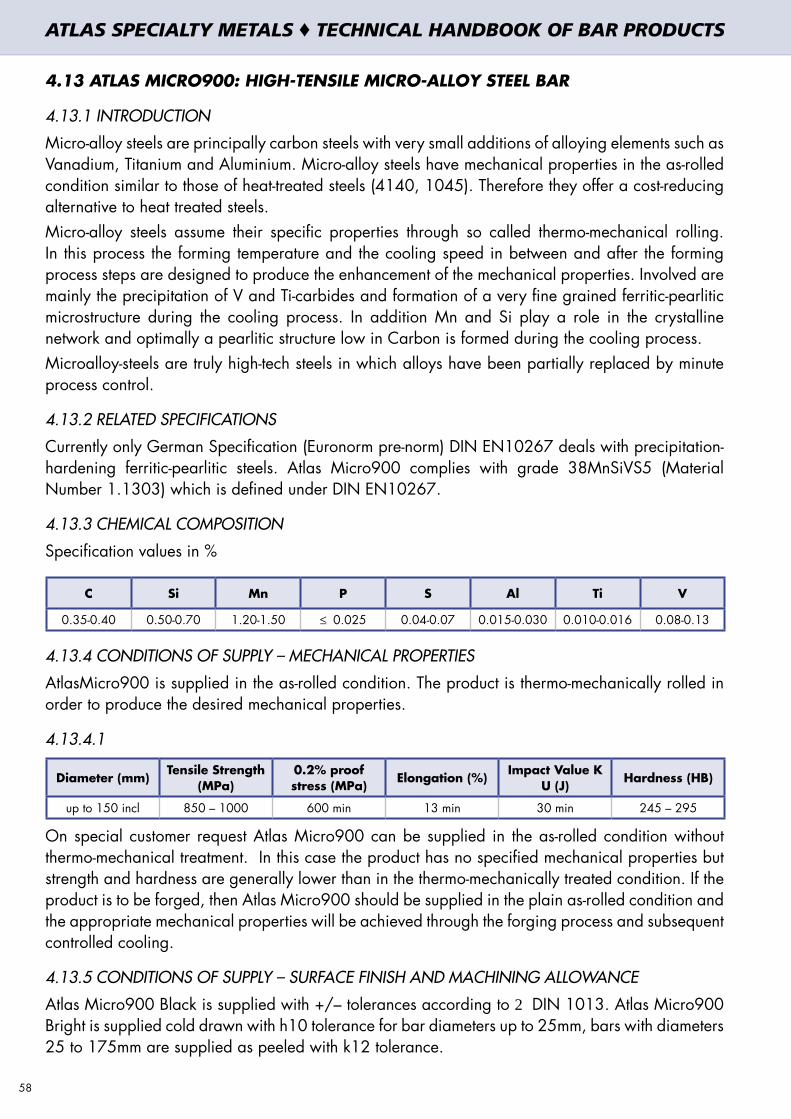
4.13 ATLAS MICRO900: HIGH-TENSILE MICRO-ALLOY STEEL BAR
4.13.1 INTRODUCTION
Micro-alloy steels are principally carbon steels with very small additions of alloying elements such as Vanadium, Titanium and Aluminium. Micro-alloy steels have mechanical properties in the as-rolled condition similar to those of heat-treated steels (4140, 1045). Therefore they offer a cost-reducing alternative to heat treated steels.Micro-alloy steels assume their specific properties through so called thermo-mechanical rolling. In this process the forming temperature and the cooling speed in between and after the forming process steps are designed to produce the enhancement of the mechanical properties. Involved are mainly the precipitation of V and Ti-carbides and formation of a very fine grained ferritic-pearlitic microstructure during the cooling process. In addition Mn and Si play a role in the crystalline network and optimally a pearlitic structure low in Carbon is formed during the cooling process.Microalloy-steels are truly high-tech steels in which alloys have been partially replaced by minute process control.
4.13.2 RELATED SPECIFICATIONS
Currently only German Specification (Euronorm pre-norm) DIN EN10267 deals with precipitation-hardening ferritic-pearlitic steels. Atlas Micro900 complies with grade 38MnSiVS5 (Material Number 1.1303) which is defined under DIN EN10267.
4.13.3 CHEMICAL COMPOSITION
Specification values in %
C Si Mn P S Al Ti V
0.35-0.40 0.50-0.70 1.20-1.50 ≤ 0.025 0.04-0.07 0.015-0.030 0.010-0.016 0.08-0.13
4.13.4 CONDITIONS OF SUPPLY – MECHANICAL PROPERTIES
AtlasMicro900 is supplied in the as-rolled condition. The product is thermo-mechanically rolled in order to produce the desired mechanical properties.
4.13.4.1
Diameter (mm) Tensile Strength (MPa)
0.2% proof stress (MPa) Elongation (%) Impact Value K
U (J) Hardness (HB)
up to 150 incl 850 – 1000 600 min 13 min 30 min 245 – 295
On special customer request Atlas Micro900 can be supplied in the as-rolled condition without thermo-mechanical treatment. In this case the product has no specified mechanical properties but strength and hardness are generally lower than in the thermo-mechanically treated condition. If the product is to be forged, then Atlas Micro900 should be supplied in the plain as-rolled condition and the appropriate mechanical properties will be achieved through the forging process and subsequent controlled cooling.
4.13.5 CONDITIONS OF SUPPLY – SURFACE FINISH AND MACHINING ALLOWANCE
Atlas Micro900 Black is supplied with +/– tolerances according to 2 DIN 1013. Atlas Micro900 Bright is supplied cold drawn with h10 tolerance for bar diameters up to 25mm, bars with diameters 25 to 175mm are supplied as peeled with k12 tolerance.
58
ATLAS SPECIALTY METALS ♦ TECHNICAL HANDBOOK OF BAR PRODUCTS

4.13.6 MACHINING ALLOWANCES FOR ATLAS MICRO900 ROUND BAR (MM ON DIAMETER)
Bar diameter (mm)Black (hot rolled) Bright (drawn or peeled bar)
part length <120mm part length >120mm part length <120mm part length >120mm
0-50 1.4mm 1.4 + 4mm/m 1.0mm 1.0 + 4mm/m
50-100 1.7mm 1.7 + 4mm/m 1.0mm 1.0 + 4mm/m
100-150 2.0mm 2.0 + 5mm/m 1.0mm 1.0 + 4mm/m
150-210 2.3mm 2.3 + 5mm/m 1.5mm 1.5 + 4mm/m
Hot-rolling surface defects are retained in cold drawing. For bright bar in the range of cold drawing (up to 25mm) it is essential to take machining allowance into account. Peeled bar is generally free of surface defects. A certain allowance for surface defects is recommended however, as minor defects are permitted by the various national standards (AS, EN, etc.). A minor sulphur addition to this grade gives significantly improved machinability.
4.13.7 FORGING
Components are to be forged at 1200°C ± 30°C. Forging finish temperature of the part should be in the range of 1000 – 1100°C. Down to a temperature of 600 – 650°C a controlled cooling is to be applied depending on the weight of the part as shown in the table.
Cooling speed
Weight of part (kg) ≤ 1.5 1.5 – 3.5 3.5 – 7.5 7.5 – 15.0 15.0 – 25.0
°C/min surface 120 90 70 55 46
°C/min core 90 80 60 47 40
Final cooling to room temperature should occur in a container.
4.13.8 SURFACE HARDENING
Atlas Micro900 can be induction hardened and when tempered at 150 – 200°C it achieves a surface hardness of 52-55 HRC.
4.13.9 WELDING
Under certain conditions the material can be fusion welded. It is recommended to consult a welding expert concerning the most suitable welding procedure.
4.13.10 APPLICATIONS OF ATLAS MICRO900
Medium-high stressed shafts and components where the use of carbon steel 1045 would not be appropriate. Reasons for using Atlas Micro900 are the higher yield and fatigue strength, better through hardening of the material and superior impact properties compared to plain carbon steels like 1045. Machinability of Micro900 is also significantly better than that of 1045 steel. Substitution of 1045 is particularly attractive if a 1045 steel component is to be heat treated.
Medium-high stressed components where currently 4140 steel is used. Atlas Micro900 offers mechanical properties similar to those of 4140, though its impact properties are generally not as good as those of 4140 steel. Substitution of 4140 by Atlas Micro900 offers a significant cost saving potential both in material costs and machining cost, as the machinability of Micro900 is substantially better than that of 4140 steel.
59
ATLAS SPECIALTY METALS ♦ TECHNICAL HANDBOOK OF BAR PRODUCTS
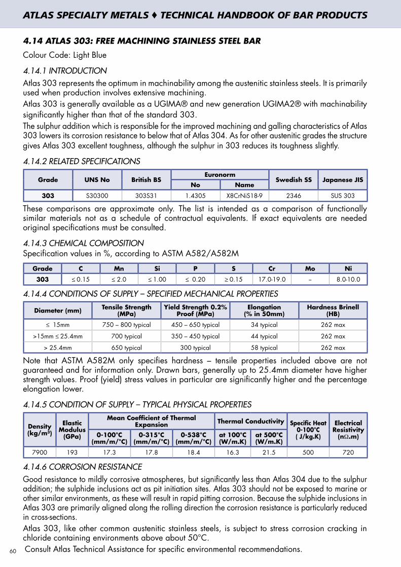
4.14 ATLAS 303: FREE MACHINING STAINLESS STEEL BAR
Colour Code: Light Blue
4.14.1 INTRODUCTIONAtlas 303 represents the optimum in machinability among the austenitic stainless steels. It is primarily used when production involves extensive machining. Atlas 303 is generally available as a UGIMA® and new generation UGIMA2® with machinability significantly higher than that of the standard 303.The sulphur addition which is responsible for the improved machining and galling characteristics of Atlas 303 lowers its corrosion resistance to below that of Atlas 304. As for other austenitic grades the structure gives Atlas 303 excellent toughness, although the sulphur in 303 reduces its toughness slightly.
4.14.2 RELATED SPECIFICATIONS
Grade UNS No British BSEuronorm
Swedish SS Japanese JISNo Name
303 S30300 303S31 1.4305 X8CrNiS18-9 2346 SUS 303
These comparisons are approximate only. The list is intended as a comparison of functionally similar materials not as a schedule of contractual equivalents. If exact equivalents are needed original specifications must be consulted.
4.14.3 CHEMICAL COMPOSITIONSpecification values in %, according to ASTM A582/A582M
Grade C Mn Si P S Cr Mo Ni
303 ≤ 0.15 ≤ 2.0 ≤ 1.00 ≤ 0.20 ≥ 0.15 17.0-19.0 -- 8.0-10.0
4.14.4 CONDITIONS OF SUPPLY – SPECIFIED MECHANICAL PROPERTIES
Diameter (mm) Tensile Strength (MPa)
Yield Strength 0.2% Proof (MPa)
Elongation (% in 50mm)
Hardness Brinell (HB)
≤ 15mm 750 – 800 typical 450 – 650 typical 34 typical 262 max
>15mm ≤ 25.4mm 700 typical 350 – 450 typical 44 typical 262 max
> 25.4mm 650 typical 300 typical 58 typical 262 max
Note that ASTM A582M only specifies hardness – tensile properties included above are not guaranteed and for information only. Drawn bars, generally up to 25.4mm diameter have higher strength values. Proof (yield) stress values in particular are significantly higher and the percentage elongation lower.
4.14.5 CONDITION OF SUPPLY – TYPICAL PHYSICAL PROPERTIES
Density (kg/m³)
Elastic Modulus
(GPa)
Mean Coefficient of Thermal Expansion Thermal Conductivity Specific Heat
0-100°C ( J/kg.K)
Electrical Resistivity
(nΩ.m)0-100°C (mm/m/°C)
0-315°C (mm/m/°C)
0-538°C (mm/m/°C)
at 100°C (W/m.K)
at 500°C (W/m.K)
7900 193 17.3 17.8 18.4 16.3 21.5 500 720
4.14.6 CORROSION RESISTANCEGood resistance to mildly corrosive atmospheres, but significantly less than Atlas 304 due to the sulphur addition; the sulphide inclusions act as pit initiation sites. Atlas 303 should not be exposed to marine or other similar environments, as these will result in rapid pitting corrosion. Because the sulphide inclusions in Atlas 303 are primarily aligned along the rolling direction the corrosion resistance is particularly reduced in cross-sections.Atlas 303, like other common austenitic stainless steels, is subject to stress corrosion cracking in chloride containing environments above about 50°C. Consult Atlas Technical Assistance for specific environmental recommendations.60
ATLAS SPECIALTY METALS ♦ TECHNICAL HANDBOOK OF BAR PRODUCTS

4.14.7 HEAT RESISTANCE
Good oxidation resistance in intermittent service to 760°C and in continuous service to 870°C. Continuous use in the 425-860°C range is not usually recommended due to carbide precipitation – Atlas 303 usually does not have a low carbon content so is susceptible to sensitisation, which can lead to intergranular corrosion.
4.14.8 PROCESSINGAs well as reducing the corrosion resistance, the sulphur additions in 303 also result in poor weldability and reduced formability compared to Grade 304. Sharp bends should not be attempted in 303. A practical compromise alternative may be a 304 Ugima Improved Machinability grade - this does not machine as readily as 303, but does offer better formability (as well as excellent weldability and significantly better corrosion resistance).
4.14.9 CONDITIONS OF SUPPLY – FINISH, DIMENSIONS AND TOLERANCES
4.14.9.1 Surface Finish
Round bar up to 25.4mm diameter is all cold drawn. Round bars over 25.4 and up to 127.00mm diameter are smooth-turned and polished. Round bars over 127.00mm diameter are all peeled.
All hexagon bar and all square bar is cold drawn.
4.14.9.2 Diameter and A/F tolerances
Round Bar: Cold drawn h9; Smooth-turned and Polished h10; Peeled up to 160mm k12; Peeled over 160mm +1.5mm/-0; Centreless ground h9 or h8
Square Bar: h11; Hex Bar: h11.
4.14.9.3 Straightness – maximum deviation from a straight line
Round Bar: 1.5mm in 1500mm and may not exceed: 1.5mm x length in mm / 1500mm Squares and Hexagon: 1.5mm in 1500mm and may not exceed: 1.5mm x length in mm / 1500mm
Other tolerances may be supplied for more critical applications upon enquiry.
4.14.9.4 Length Tolerance
Sizes up to 25.4mm: Mill Lengths and Set Lengths, +50mm/-0Sizes up from 25.4mm to 50.8mm: Mill Lengths and Set Lengths, +100mm/-0Sizes over 50.8mm: Mill Lengths and Set Lengths, ± 300mm (varies depending on size)
4.14.10 UGIMA® 303 AND UGIMA2® 303 FOR TOP PERFORMANCE IN MACHINING
A UGIMA® improved machinability version of grade 303 is available in round, hexagon and square bar. UGIMA® 303 machines significantly better than standard 303, enabling a higher rate of metal removal and lower tool wear in many operations. Surface quality and reliability of machining results will improve too when using UGIMA® 303. UGIMA2® 303, is the new generation product offering further benefits of improved chip-breakability, substantially longer tool life and productivity benefits also in the low machining speed range.
For UGIMA® 303 and UGIMA2® 303 detailed set-up tables are available on request, specifying machining parameters (surface speed, feed rate, depth of cut and type of tool) for high-speed steel tooling and carbide insert tooling for the most common machining operations (roughing, finishing, drilling, parting-off etc.). Machinability assistance is available for optimal set-up and problem-solving for specific machining jobs.
61
ATLAS SPECIALTY METALS ♦ TECHNICAL HANDBOOK OF BAR PRODUCTS

4.14.11 HEAT TREATMENT
The following temperature ranges are applicable for the respective heat treatment operations.
Forging Annealing
900 – 1200°C 1010 – 1120°C
Cool rapidly after annealing. Atlas 303 cannot be hardened by thermal treatment.
4.14.12 WELDINGNot generally recommended but, if unavoidable use Grade 308L or 309 electrodes. AS 1554.6 does not pre-qualify welding of 303. Welds must be annealed for maximum corrosion resistance, but even then poor mechanical and corrosion properties will result.
4.14.13 APPLICATIONS OF ATLAS 303 Nuts and bolts. Bushings. Shafts. Electrical switchgear components. Gears. In general any component that is heavily machined and where the corrosion resistance and fabrication properties of 303 are viable.
4.14.14 POSSIBLE ALTERNATIVE GRADES
Grade Why it may be chosen instead of Atlas 303
303UX UGIMA® 303UX offers the highest machinability for long run repetition machining.
304Better corrosion resistance, formability or weldability are needed, at the expense of lower machinability. Consider UGIMA® 304 or UGIMA® 304Cu
316Higher resistance to pitting and crevice corrosion is required, in chloride environments. A lower machinability can be accepted.
416Even higher machinability than 303 is needed, and a lower corrosion resistance can be tolerated. Or hardening by thermal treatment is required, while maintaining a high machinability.
62
ATLAS SPECIALTY METALS ♦ TECHNICAL HANDBOOK OF BAR PRODUCTS

4.15 ATLAS 304: STAINLESS STEEL BAR
Colour Code: Lilac/Turquoise4.15.1 INTRODUCTIONGrade 304 is the standard “18/8” stainless. It has excellent forming and welding characteristics. Grade 304L, the low carbon version of 304, does not require post-weld annealing and so is extensively used in heavy gauge components. The austenitic structure also gives these grades excellent toughness, even down to cryogenic temperatures.
4.15.2 RELATED SPECIFICATIONS
Grade UNS No British BSEuronorm
Swedish SS Japanese JISNo Name
304 S30400 304S31 1.4301 X5CrNi18-10 2332 SUS 304
304L S30403 304S11 1.4306 X2CrNi19-11 2352 SUS 304L
These comparisons are approximate only. The list is intended as a comparison of functionally similar materials not as a schedule of contractual equivalents. If exact equivalents are needed original specifications must be consulted.
4.15.3 CHEMICAL COMPOSITIONSpecification values in %, according to ASTM A276
Grade C Mn Si P S Cr Mo Ni N
304 ≤ 0.08 ≤ 2.0 ≤ 1.00 ≤ 0.045 ≤ 0.030 18.0-20.0 8.0-11.0
304L ≤ 0.03 ≤ 2.0 ≤ 1.00 ≤ 0.045 ≤ 0.030 18.0-20.0 8.0-12.0
Atlas304 bar is generally stocked in “Dual Certified” form. These products have chemical and mechanical properties complying with both 304 and 304L specifications. Such dual certified product does not meet 304H specifications and may be unacceptable for high temperature (over about 500°C) applications.
4.15.4 CONDITIONS OF SUPPLY – SPECIFIED MECHANICAL PROPERTIESValues below are specified values according to ASTM A276, condition A, for cold finished 304 bars.
Diameter (mm) Tensile Strength (MPa) min
0.2% proof stress (MPa) min
Elongation (% in 50mm) min
Reduction of Area (%) min
≤ 12.70 520 310 30 40
>12.70 515 205 30 40
4.15.5 CONDITION OF SUPPLY – TYPICAL PHYSICAL PROPERTIES
Density (kg/m³)
Elastic Modulus
(GPa)
Mean Coefficient of Thermal Expansion Thermal Conductivity Specific Heat 0-100°C (J/kg.K)
Electrical Resistivity
(nΩ.m)0-100°C (mm/m/°C)
0-315°C (mm/m/°C)
0-538°C (mm/m/°C)
at 100°C (W/m.K)
at 500°C (W/m.K)
7900 193 17.2 17.8 18.4 16.3 21.5 500 720
4.15.6 CORROSION RESISTANCEExcellent in a wide range of atmospheric environments and many corrosive media. Subject to pitting and crevice corrosion in warm chloride environments, and to stress corrosion cracking above about 50°C. Considered resistant to potable water with up to about 200mg/L chlorides at ambient temperatures, reducing to about 150mg/L at 60°C. Consult Atlas Technical Assistance for specific environmental recommendations.
4.15.7 HEAT RESISTANCEGood oxidation resistance in intermittent service to 870°C and in continuous service to 925°C. Continuous use of 304 in the 425-860°C range is not recommended if subsequent aqueous corrosion resistance is important, but 304L and dual certified product 304/304L does not suffer from this problem. For temperatures above 500°C specific high-temperature grades would normally be chosen such as 304H, 321H, 310 or S30815. 63
ATLAS SPECIALTY METALS ♦ TECHNICAL HANDBOOK OF BAR PRODUCTS

4.15.8 CONDITIONS OF SUPPLY – FINISH, DIMENSIONS AND TOLERANCES
4.15.8.1 Surface Finish Round bar up to 25.4mm diameter is all cold drawn. Round bars over 25.4 and up to 127.00mm diameter are smooth-turned and polished. Round bars over 127.00mm diameter are all peeled. All hexagon bar and all square bar is cold drawn.
4.15.8.2 Diameter and A/F tolerances Round Bar: Cold drawn h9; Smooth-turned and Polished h10; Peeled up to 160mm k12; Peeled
over 160mm +1.5mm/-0; Centreless ground h9 or h8Square Bar: h11; Hex Bar: h11.4.15.8.3 Straightness – maximum deviation from a straight lineRound Bar: 1.5mm in 1500mm and may not exceed: 1.5mm x length in mm / 1500mm Squares and Hexagon: 1.5mm in 1500mm and may not exceed: 1.5mm x length in mm / 1500mmOther tolerances may be supplied for more critical applications upon enquiry.4.15.8.4 Length Tolerance Sizes up to 25.4mm: Mill Lengths and Set Lengths, +50mm/-0Sizes up from 25.4mm to 50.8mm: Mill Lengths and Set Lengths, +100mm/-0Sizes over 50.8mm: Mill Lengths and Set Lengths, +300mm (varies depending on size)
4.15.9 UGIMA® 304 FOR TOP PERFORMANCE IN MACHININGA UGIMA® improved machinability version of grade 304 is available in round, hexagon and square bar. UGIMA® 304 machines significantly better than standard 304 or 304L, enabling a higher rate of metal removal and lower tool wear in many operations. Surface quality and reliability of machining results will improve too when using UGIMA® 304. For UGIMA® 304 detailed set-up table are available on request, specifying machining parameters (surface speed, feed rate, depth of cut and type of tool) for high-speed steel tooling and carbide insert tooling for the most common machining operations (roughing, finishing, drilling, parting-off etc.). Machinability assistance is available for optimal set-up and problem-solving for specific machining jobs.4.15.10 HEAT TREATMENTThe following temperature ranges are applicable for the respective heat treatment operations.
Forging Annealing
900 – 1200°C 1010 – 1120°C
Cool rapidly after annealing. Atlas 304 cannot be hardened by thermal treatment.
4.15.11 WELDINGExcellent weldability by all standard fusion methods, both with and without filler metals. AS 1554.6 pre-qualifies welding of 304 with Grade 308 and 304L with 308L rods or electrodes (and with their high silicon equivalents). Heavy welded sections in Grade 304 may require post-weld annealing for maximum corrosion resistance. This is not required for Grade 304L.
4.15.12 APPLICATIONS OF ATLAS 304 Food processing equipment, particularly in beer brewing, milk processing & wine making. Kitchen appliances and equipment. Heat exchanger components. Threaded fasteners. Springs.
4.15.13 POSSIBLE ALTERNATIVE GRADES
Grade Why it may be chosen instead of 304/L
304Cu Lower work hardening rate is needed for cold forging of screws, bolts and rivets. Higher machinability than 304/L.
303 Higher machinability needed, and the lower corrosion resistance, formability and weldability are acceptable.
316 Higher resistance to pitting and crevice corrosion is required, in chloride environments.
430 A lower cost is required, and the reduced corrosion resistance and fabrication characteristics are acceptable.64
ATLAS SPECIALTY METALS ♦ TECHNICAL HANDBOOK OF BAR PRODUCTS

4.16 ATLAS 316: STAINLESS STEEL BARColour Code: Bottle Green/Marigold4.16.1 INTRODUCTIONAtlas 316 is the standard molybdenum-bearing stainless steel, second in importance to 304 amongst the austenitic stainless steels. The molybdenum gives 316 better overall corrosion resistant properties than Grade 304, particularly higher resistance to pitting and crevice corrosion in chloride environments. It has excellent forming and welding characteristics. Post-weld annealing is not required when welding thin sections. Atlas 316L is immune from sensitisation (grain boundary carbide precipitation) and so is extensively used in heavy gauge welded components (over about 6mm). The austenitic structure also gives these grades excellent toughness, even down to cryogenic temperatures.
4.16.2 RELATED SPECIFICATIONS
Grade UNS No British BSEuronorm
Swedish SS Japanese JISNo Name
316 S31600 316S31 1.4401 X5CrNiMo17-12-2 2347 SUS 316
316L S31603 316S11 1.4404 X2CrNiMo17-12-2 2348 SUS 316L
These comparisons are approximate only. The list is intended as a comparison of functionally similar materials not as a schedule of contractual equivalents. If exact equivalents are needed original specifications must be consulted.
4.16.3 CHEMICAL COMPOSITIONSpecification values in %, according to ASTM A276
Grade C Mn Si P S Cr Mo Ni
316 ≤ 0.08 ≤ 2.0 ≤ 1.00 ≤ 0.045 ≤ 0.030 16.0-18.0 2.0-3.0 10.0-14.0
316L ≤ 0.03 ≤ 2.0 ≤ 1.00 ≤ 0.045 ≤ 0.030 16.0-18.0 2.0-3.0 10.0-14.0
Atlas316 bar is generally stocked in “Dual Certified” form. These products have chemical and mechanical properties complying with both 316 and 316L specifications. Such dual certified product does not meet 316H specifications and may be unacceptable for high temperature (over about 500°C) applications.
4.16.4 CONDITIONS OF SUPPLY – SPECIFIED MECHANICAL PROPERTIESValues below are specified values according to ASTM A276, condition A, for cold finished bars.
Diameter (mm) Tensile Strength (MPa) min
0.2% proof stress (MPa) min
Elongation (% in 50mm) min
Reduction of Area (%) min
≤ 12.70 620 310 30 40
>12.70 515 205 30 40
4.16.5 CONDITION OF SUPPLY – TYPICAL PHYSICAL PROPERTIES
Density (kg/m³)
Elastic Modulus
(GPa)
Mean Coefficient of Thermal Expansion Thermal Conductivity Specific Heat 0-100°C (J/kg.K)
Electrical Resistivity
(nΩ.m)0-100°C
(mm/m/°C)0-315°C
(mm/m/°C)0-538°C
(mm/m/°C)at 100°C (W/m.K)
at 500°C (W/m.K)
8000 193 15.9 16.2 17.5 16.3 21.5 500 740
4.16.6 CORROSION RESISTANCEExcellent in a range of atmospheric environments and many corrosive media - generally more resistant than 304. Subject to pitting and crevice corrosion in warm chloride environments, and to stress corrosion cracking above about 50°C. Considered resistant to potable water with up to about 1000mg/L chlorides at ambient temperatures, reducing to about 500mg/L at 60°C. 316 is usually regarded as the standard “marine grade stainless steel”, but it is not resistant to warm sea water. In many marine environments Atlas 316 does exhibit surface corrosion, usually visible as brown staining. This is particularly associated with crevices and rough surface finish. Consult Atlas Technical Assistance for specific environmental recommendations. 65
ATLAS SPECIALTY METALS ♦ TECHNICAL HANDBOOK OF BAR PRODUCTS
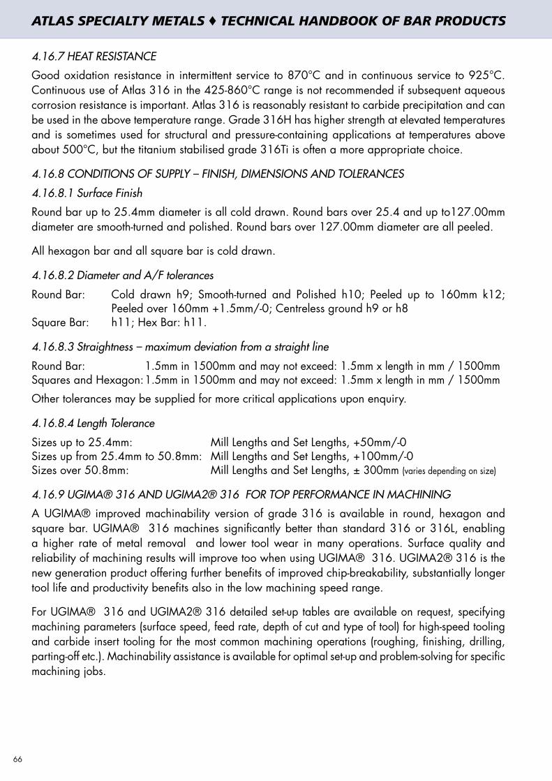
4.16.7 HEAT RESISTANCE
Good oxidation resistance in intermittent service to 870°C and in continuous service to 925°C. Continuous use of Atlas 316 in the 425-860°C range is not recommended if subsequent aqueous corrosion resistance is important. Atlas 316 is reasonably resistant to carbide precipitation and can be used in the above temperature range. Grade 316H has higher strength at elevated temperatures and is sometimes used for structural and pressure-containing applications at temperatures above about 500°C, but the titanium stabilised grade 316Ti is often a more appropriate choice.
4.16.8 CONDITIONS OF SUPPLY – FINISH, DIMENSIONS AND TOLERANCES
4.16.8.1 Surface Finish
Round bar up to 25.4mm diameter is all cold drawn. Round bars over 25.4 and up to127.00mm diameter are smooth-turned and polished. Round bars over 127.00mm diameter are all peeled.
All hexagon bar and all square bar is cold drawn.
4.16.8.2 Diameter and A/F tolerances
Round Bar: Cold drawn h9; Smooth-turned and Polished h10; Peeled up to 160mm k12; Peeled over 160mm +1.5mm/-0; Centreless ground h9 or h8
Square Bar: h11; Hex Bar: h11.
4.16.8.3 Straightness – maximum deviation from a straight line
Round Bar: 1.5mm in 1500mm and may not exceed: 1.5mm x length in mm / 1500mm Squares and Hexagon: 1.5mm in 1500mm and may not exceed: 1.5mm x length in mm / 1500mm
Other tolerances may be supplied for more critical applications upon enquiry.
4.16.8.4 Length Tolerance
Sizes up to 25.4mm: Mill Lengths and Set Lengths, +50mm/-0Sizes up from 25.4mm to 50.8mm: Mill Lengths and Set Lengths, +100mm/-0Sizes over 50.8mm: Mill Lengths and Set Lengths, ± 300mm (varies depending on size)
4.16.9 UGIMA® 316 AND UGIMA2® 316 FOR TOP PERFORMANCE IN MACHINING
A UGIMA® improved machinability version of grade 316 is available in round, hexagon and square bar. UGIMA® 316 machines significantly better than standard 316 or 316L, enabling a higher rate of metal removal and lower tool wear in many operations. Surface quality and reliability of machining results will improve too when using UGIMA® 316. UGIMA2® 316 is the new generation product offering further benefits of improved chip-breakability, substantially longer tool life and productivity benefits also in the low machining speed range.
For UGIMA® 316 and UGIMA2® 316 detailed set-up tables are available on request, specifying machining parameters (surface speed, feed rate, depth of cut and type of tool) for high-speed tooling and carbide insert tooling for the most common machining operations (roughing, finishing, drilling, parting-off etc.). Machinability assistance is available for optimal set-up and problem-solving for specific machining jobs.
66
ATLAS SPECIALTY METALS ♦ TECHNICAL HANDBOOK OF BAR PRODUCTS

4.16.10 HEAT TREATMENT
The following temperature ranges are applicable for the respective heat treatment operations.
Forging Annealing
900 – 1200°C 1010 – 1120°C
Cool rapidly after annealing. Atlas 316 cannot be hardened by thermal treatment.
4.16.11 WELDING
Excellent weldability by all standard fusion methods, both with and without filler metals. AS 1554.6 pre-qualifies welding of 316 with Grade 316 and 316L with Grade 316L rods or electrodes (or their high silicon equivalents). Both can be applied for Atlas 316. Heavy welded sections do not require post-weld annealing for maximum corrosion resistance. Grade 316Ti may also be used as an alternative to Atlas 316 for heavy section welding.
4.16.12 APPLICATIONS OF ATLAS 316
Food processing equipment. Laboratory equipment. Architectural panelling, railings & trim. Boat fittings. Heat exchangers. Components for mining, quarrying & water filtration. Threaded fasteners. Springs.
4.16.13 POSSIBLE ALTERNATIVE GRADES
Grade Why it may be chosen instead of Atlas 316/316L
316Ti Better resistance to temperatures of around 600-900°C is needed.
904L Much higher resistance to chlorides at elevated temperatures, with good formability
2205 Much higher resistance to chlorides at elevated temperatures, and higher strength than 316
67
ATLAS SPECIALTY METALS ♦ TECHNICAL HANDBOOK OF BAR PRODUCTS

4.17 ATLAS 420: STAINLESS STEEL BARColour Code: Rose Pink4.17.1 INTRODUCTIONGrade 420 stainless steel is a higher carbon version of 410 which can be hardened by a quench-and-temper heat treatment. It contains a minimum of 12 per cent chromium, just sufficient to give corrosion resistance in fairly mild environment. It has good ductility in the annealed condition but is capable of being hardened up to Rockwell Hardness 50HRC, the highest hardness of the 12 per cent chromium grades. Its best corrosion resistance is achieved when the metal is hardened and surface ground or polished. This datasheet describes the standard Atlas 420. Variants with carbon content controlled within particular ranges are also available, usually designated 420A (lowest carbon) and increasing through 420B and 420C. Consult Atlas for details.Martensitic stainless steels are optimised for high hardness, and other properties are to some degree compromised. Fabrication must be by methods that allow for poor weldability and usually also allow for a final harden and temper heat treatment. Corrosion resistance is lower than the common austenitic grades, and their useful operating temperature range is limited by their loss of ductility at sub-zero temperatures and loss of strength by over-tempering at elevated temperatures.
4.17.2 RELATED SPECIFICATIONS
Grade UNS No British BSEuronorm
Swedish SS Japanese JISNo Name
420 S42000 420S37 1.4021 X20Cr13 2303 SUS 420J1
These comparisons are approximate only. The list is intended as a comparison of functionally similar materials not as a schedule of contractual equivalents. If exact equivalents are needed original specifications must be consulted.
4.17.3 CHEMICAL COMPOSITION
Specification values in %, according to ASTM A276Grade C Mn Si P S Cr Mo Ni
420 ≤ 0.15 ≤ 1.0 ≤ 1.0 ≤ 0.040 ≤ 0.030 12.0-14.0 -- --
4.17.4 CONDITIONS OF SUPPLY – SPECIFIED MECHANICAL PROPERTIES Diameter
(mm) Condition Tensile Strength (MPa)
0.2% proof stress (MPa) min
Elongation (% in 50mm) min
Reduction of Area (%) min
Hardness (HB 30)
all Annealed ≤ 230
Up to 160 Hardened & Tempered 850 – 1000 600 12 50
4.17.5 CONDITION OF SUPPLY – TYPICAL PHYSICAL PROPERTIES
Density (kg/m³)
Elastic Modulus
(GPa)
Mean Coefficient of Thermal Expansion Thermal Conductivity Specific Heat 0-100°C (J/kg.K)
Electrical Resistivity
(nΩ.m)0-100°C
(mm/m/°C)0-315°C
(mm/m/°C)0-538°C
(mm/m/°C)at 100°C (W/m.K)
at 500°C (W/m.K)
7700 200 10.3 10.8 11.7 24.9 - 460 550
4.17.6 CORROSION RESISTANCEGrade 420 has good resistance in the hardened condition to the atmosphere, foods, fresh water and mild alkalies or acids. Corrosion resistance is lower in the annealed condition.Performance is best with a centreless ground surface finish. Less corrosion resistant than the austenitic grades and also less than 17% chromium ferritic alloys such as Grade 430; 420 also has slightly lower resistance than grade 410.Consult Atlas Technical Assistance for specific environmental recommendations.
4.17.7 HEAT RESISTANCENot recommended for use in temperatures above the relevant tempering temperature, because of reduction in mechanical properties. The scaling temperature is approximately 650°C.68
ATLAS SPECIALTY METALS ♦ TECHNICAL HANDBOOK OF BAR PRODUCTS

4.17.8 CONDITIONS OF SUPPLY – FINISH, DIMENSIONS AND TOLERANCES
4.17.8.1 Surface Finish Round bar up to 25.4mm diameter is all cold drawn. Round bars over 25.4 and up to 127.00mm diameter are smooth-turned and polished. Round bars over 127.00mm diameter are all peeled. All hexagon bar and all square bar is cold drawn.
4.17.8.2 Diameter and A/F tolerances Round Bar: Cold drawn h9; Smooth-turned and Polished h10; Peeled up to 160mm k12; Peeled
over 160mm +1.5mm/-0; Centreless ground h9 or h8Square Bar: h11; Hex Bar: h11.
4.17.8.3 Straightness – maximum deviation from a straight lineRound Bar: 1.5mm in 1500mm and may not exceed: 1.5mm x length in mm / 1500mm Squares and Hexagon: 1.5mm in 1500mm and may not exceed: 1.5mm x length in mm / 1500mmOther tolerances may be supplied for more critical applications upon enquiry.
4.17.8.4 Length Tolerance Sizes up to 25.4mm: Mill Lengths and Set Lengths, +50mm/-0Sizes up from 25.4mm to 50.8mm: Mill Lengths and Set Lengths, +100mm/-0Sizes over 50.8mm: Mill Lengths and Set Lengths, ± 300mm (varies depending on size)
4.17.9 UGIMA® 420 FOR TOP PERFORMANCE IN MACHININGA UGIMA® improved machinability version of grade 420 is available in round, hexagon and square bar. UGIMA®420 machines significantly better than standard 420, enabling a higher rate of metal removal and lower tool wear in many operations. Surface quality and reliability of machining results will improve too when using UGIMA®420. For UGIMA®420 detailed set-up tables are available on request, specifying machining parameters (surface speed, feed rate, depth of cut and type of tool) for high-speed steel tooling and carbide insert tooling for the most common machining operations (roughing, finishing, drilling, parting-off etc.). Machinability assistance is available for optimal set-up and problem-solving for specific machining jobs.
4.17.10 HEAT TREATMENTThe following temperature ranges are applicable for the respective heat treatment operations.
Forging Annealing Hardening Tempering
800 – 1100°C 840 – 900°C 980 – 1035°C 600 – 750°C
After annealing execute a slow furnace cool to 600°C and then air cool.The tempering range 425 – 600°C should be avoided.
4.17.11 WELDINGPre-heat to 150-320°C and post-heat at 610-760°C. Grade 420 coated welding rods are recommended for high strength joints, where a post-weld hardening and tempering heat treatment is to be carried out. If parts are to be used in the “as welded” condition, a ductile joint can be achieved by using Grade 309 filler rod. AS 1554.6 pre-qualifies welding of 420 with Grade 309 rods or electrodes.
4.17.12 APPLICATIONS OF ATLAS420 Shafts and axles, pump components. Valve cones. Surgical instruments. Needle valves. Shear blades.
4.17.13 POSSIBLE ALTERNATIVE GRADESGrade Why it may be chosen instead of Atlas420
410 Only a lower hardened strength is needed.
416 High machinability is required, and the lower hardened strength and lower corrosion resistance of 416 is acceptable.
440C A higher hardened strength or hardness than can be obtained from 420 is needed.
“specials” Variations of 420 are available to special order often identified as 420A, 420B etc. These offer higher hardness, corrosion resistance and machinability for particular applications. 69
ATLAS SPECIALTY METALS ♦ TECHNICAL HANDBOOK OF BAR PRODUCTS

4.18 ATLAS 431: STAINLESS STEEL BAR
Colour Code: Signal Red
4.18.1 INTRODUCTION
This heat treatable martensitic, nickel-bearing grade has the best corrosion resistance properties of all the martensitic grades. It has excellent tensile and torque strength, and good toughness, making it ideally suited to shafting and bolt applications. It can be hardened to approximately 40HRC. Because of its high yield strength, this grade is not readily cold worked and is therefore not recommended for use in operations such as cold heading, bending, deep drawing or spinning.
Martensitic stainless steels are optimised for high hardness, and other properties are to some degree compromised. Fabrication must be by methods that allow for poor weldability and usually also allow for a final harden and temper heat treatment. Corrosion resistance is generally lower than the common austenitic grades, and their useful operating temperature range is limited by their loss of ductility at sub-zero temperatures and loss of strength by over-tempering at elevated temperatures.
4.18.2 RELATED SPECIFICATIONS
Grade UNS No British BSEuronorm
Swedish SS Japanese JISNo Name
431 S43100 431S29 1.4057 X17CrNi16-2 2321 SUS 431
These comparisons are approximate only. The list is intended as a comparison of functionally similar materials not as a schedule of contractual equivalents. If exact equivalents are needed original specifications must be consulted.
4.18.3 CHEMICAL COMPOSITION
Specification values in %, according to ASTM A276
Grade C Mn Si P S Cr Mo Ni
431 ≤ 0.20 ≤ 1.00 ≤ 1.00 ≤ 0.040 ≤ 0.030 15.0 – 17.0 -- 1.25 – 2.50
4.18.4 CONDITIONS OF SUPPLY – SPECIFIED MECHANICAL PROPERTIES
Condition Tensile Strength (MPa) min
0.2% proof stress (MPa) min
Elongation (% in 50mm) min Hardness (HB)
Annealed -- -- -- 285 max
Hardened & Tempered 850 - 1000 665 min. 12 min. 248 - 302
Atlas 431 is generally stocked and supplied in “Condition T” to AS 1444 or BS 970, with specified tensile strength of 850 - 1000MPa. Yield and elongation are typically in conformance with the limits listed above.
ASTM A276 only lists a Condition A version of Grade 431; the annealed hardness listed above is the specified maximum. Atlas 431 is only rarely stocked in annealed Condition A.
4.18.5 CONDITION OF SUPPLY – TYPICAL PHYSICAL PROPERTIES
Density (kg/m³)
Elastic Modulus
(GPa)
Mean Coefficient of Thermal Expansion Thermal Conductivity Specific Heat 0-100°C (J/kg.K)
Electrical Resistivity
(nΩ.m)0-100°C
(mm/m/°C)0-315°C
(mm/m/°C)0-538°C
(mm/m/°C)at 100°C (W/m.K)
at 500°C (W/m.K)
7700 200 10.2 12.1 - 20.2 - 460 720
70
ATLAS SPECIALTY METALS ♦ TECHNICAL HANDBOOK OF BAR PRODUCTS

4.18.6 CORROSION RESISTANCE
Grade 431 has excellent resistance to a wide variety of corrosive media. It has reasonable resistance to salt water in cold southern waters but is unlikely to be successful in warmer tropical waters. Overall the corrosion resistance of 431 is approximately the same as or slightly below that of Grade 304.
Performance is best with a smooth surface finish, in the hardened and tempered condition.
Consult Atlas Technical Assistance for specific environmental recommendations.
4.18.7 HEAT RESISTANCE
Resists scaling in intermittent service to 925°C and in continuous service to 870°C, but is generally not recommended for use in temperatures above the relevant tempering temperature, because of reduction in mechanical properties.
4.18.8 CONDITIONS OF SUPPLY – FINISH, DIMENSIONS AND TOLERANCES
4.18.8.1 Surface Finish
Round bar up to 25.4mm diameter is all cold drawn. Round bars over 25.4 and up to127.00mm diameter are smooth-turned and polished. Round bars over 127.00mm diameter are all peeled.
All hexagon bar and all square bar is cold drawn.
4.18.8.2 Diameter and A/F tolerances
Round Bar: Cold drawn h9; Smooth-turned and Polished h10; Peeled up to 160mm k12; Peeled over 160mm +1.5mm/-0; Centreless ground h9 or h8
Square Bar: h11; Hex Bar: h11.
4.18.8.3 Straightness – maximum deviation from a straight line
Round Bar: 1.5mm in 1500mm and may not exceed: 1.5mm x length in mm / 1500mm Squares and Hexagon: 1.5mm in 1500mm and may not exceed: 1.5mm x length in mm / 1500mm
Other tolerances may be supplied for more critical applications upon enquiry.
4.18.8.4 Length Tolerance
Sizes up to 25.4mm: Mill Lengths and Set Lengths, +50mm/-0Sizes up from 25.4mm to 50.8mm: Mill Lengths and Set Lengths, +100mm/-0Sizes over 50.8mm: Mill Lengths and Set Lengths, ± 300mm (varies depending on size)
4.18.9 UGIMA® 431 FOR TOP PERFORMANCE IN MACHINING
A UGIMA® improved machinability version of grade 431 is available in round, hexagon and square bar. UGIMA® 431 machines significantly better than standard 431, enabling a higher rate of metal removal and lower tool wear in many operations. Surface quality and reliability of machining results will improve too when using UGIMA® 431. For UGIMA® 431 detailed set-up tables are available on request, specifying machining parameters (surface speed, feed rate, depth of cut and type of tool) for high-speed steel tooling and carbide insert tooling for the most common machining operations (roughing, finishing, drilling, parting-off etc.). Machinability assistance is available for optimal set-up and problem-solving for specific machining jobs.
71
ATLAS SPECIALTY METALS ♦ TECHNICAL HANDBOOK OF BAR PRODUCTS

4.18.10 HEAT TREATMENT
The following temperature ranges are applicable for the respective heat treatment operations.
Forging Annealing Hardening Tempering
900 – 1200°C 620 – 660°C 980 – 1065°C 600 – 800°C
Process Anneal - heat to 620-660°C and subsequently air cool. Full annealed is not a practical option.
Hardened by heating to 980-1065°C, holding for about 1/2 hour then quenching in air or oil. Pre-heating at 760-790°C may be useful for complex parts or those already hardened. Temper to suit mechanical requirements, at temperatures as indicated in the table.
The tempering range 425-600°C should be avoided due to reduced impact toughness, although the effect is less marked than in most other martensitic grades.
Refer to the following table for mechanical properties achieved at various tempering temperatures.
Tempering Temperature (°C)
Tensile Strength (MPa)
0.2% Proof Stress (MPa)
Elongation (% in 50mm)
Hardness Brinell (HB) Impact Izod (J)
300 1320 1020 20 380 75
400 1310 1010 22 395 80
500 1350 1030 20 395 55
600 1030 800 20 310 45
700 920 700 20 290 70
4.18.11 WELDING
Welding is difficult due to the risk of cracking. A pre-heat of 200-300°C is recommended prior to welding. Grade 410 filler rod can be used, but Grades 308L, 309 or 310 will provide more ductile welds, so long as matching properties are not required. Post-weld heat treat at 650°C.
4.18.12 APPLICATIONS OF ATLAS 431
Nuts and bolts. Propeller shafting. Pump shafts. Beater bars. Marine hardware.
4.18.13 POSSIBLE ALTERNATIVE GRADES
Grade Why it may be chosen instead of Atlas431
410 Only a lower hardened strength is needed.
416 High machinability is required, and the lower strength and lower corrosion resistance of 416 is acceptable.
440C A higher hardened strength or hardness than can be obtained from 431 is needed.
72
ATLAS SPECIALTY METALS ♦ TECHNICAL HANDBOOK OF BAR PRODUCTS
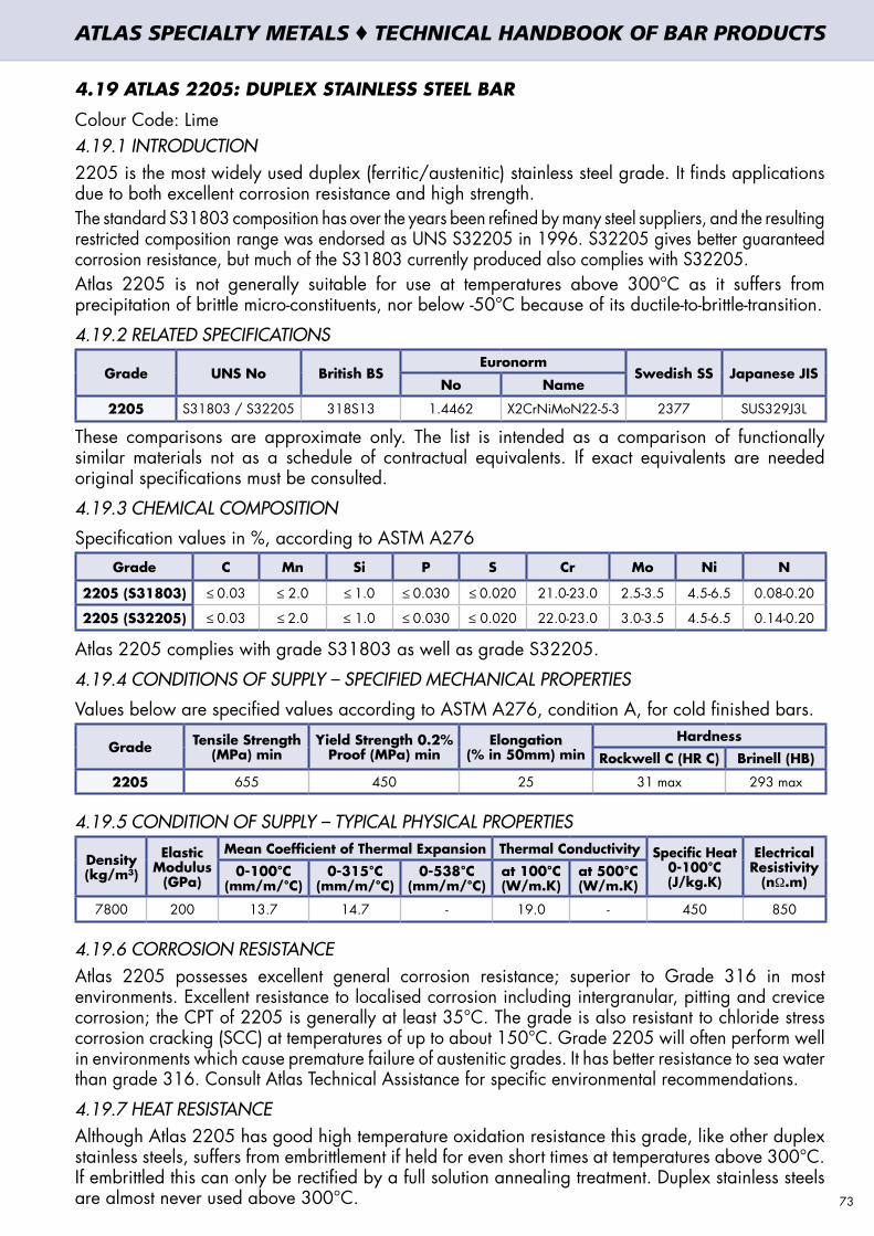
4.19 ATLAS 2205: DUPLEX STAINLESS STEEL BAR
Colour Code: Lime4.19.1 INTRODUCTION2205 is the most widely used duplex (ferritic/austenitic) stainless steel grade. It finds applications due to both excellent corrosion resistance and high strength. The standard S31803 composition has over the years been refined by many steel suppliers, and the resulting restricted composition range was endorsed as UNS S32205 in 1996. S32205 gives better guaranteed corrosion resistance, but much of the S31803 currently produced also complies with S32205.Atlas 2205 is not generally suitable for use at temperatures above 300°C as it suffers from precipitation of brittle micro-constituents, nor below -50°C because of its ductile-to-brittle-transition.
4.19.2 RELATED SPECIFICATIONS
Grade UNS No British BSEuronorm
Swedish SS Japanese JISNo Name
2205 S31803 / S32205 318S13 1.4462 X2CrNiMoN22-5-3 2377 SUS329J3L
These comparisons are approximate only. The list is intended as a comparison of functionally similar materials not as a schedule of contractual equivalents. If exact equivalents are needed original specifications must be consulted.
4.19.3 CHEMICAL COMPOSITION
Specification values in %, according to ASTM A276Grade C Mn Si P S Cr Mo Ni N
2205 (S31803) ≤ 0.03 ≤ 2.0 ≤ 1.0 ≤ 0.030 ≤ 0.020 21.0-23.0 2.5-3.5 4.5-6.5 0.08-0.20
2205 (S32205) ≤ 0.03 ≤ 2.0 ≤ 1.0 ≤ 0.030 ≤ 0.020 22.0-23.0 3.0-3.5 4.5-6.5 0.14-0.20
Atlas 2205 complies with grade S31803 as well as grade S32205.
4.19.4 CONDITIONS OF SUPPLY – SPECIFIED MECHANICAL PROPERTIES
Values below are specified values according to ASTM A276, condition A, for cold finished bars.
Grade Tensile Strength (MPa) min
Yield Strength 0.2% Proof (MPa) min
Elongation (% in 50mm) min
Hardness
Rockwell C (HR C) Brinell (HB)
2205 655 450 25 31 max 293 max
4.19.5 CONDITION OF SUPPLY – TYPICAL PHYSICAL PROPERTIES
Density (kg/m³)
Elastic Modulus
(GPa)
Mean Coefficient of Thermal Expansion Thermal Conductivity Specific Heat 0-100°C (J/kg.K)
Electrical Resistivity
(nΩ.m)0-100°C
(mm/m/°C)0-315°C
(mm/m/°C)0-538°C
(mm/m/°C)at 100°C (W/m.K)
at 500°C (W/m.K)
7800 200 13.7 14.7 - 19.0 - 450 850
4.19.6 CORROSION RESISTANCEAtlas 2205 possesses excellent general corrosion resistance; superior to Grade 316 in most environments. Excellent resistance to localised corrosion including intergranular, pitting and crevice corrosion; the CPT of 2205 is generally at least 35°C. The grade is also resistant to chloride stress corrosion cracking (SCC) at temperatures of up to about 150°C. Grade 2205 will often perform well in environments which cause premature failure of austenitic grades. It has better resistance to sea water than grade 316. Consult Atlas Technical Assistance for specific environmental recommendations.
4.19.7 HEAT RESISTANCEAlthough Atlas 2205 has good high temperature oxidation resistance this grade, like other duplex stainless steels, suffers from embrittlement if held for even short times at temperatures above 300°C. If embrittled this can only be rectified by a full solution annealing treatment. Duplex stainless steels are almost never used above 300°C. 73
ATLAS SPECIALTY METALS ♦ TECHNICAL HANDBOOK OF BAR PRODUCTS

4.19.8 CONDITIONS OF SUPPLY – FINISH, DIMENSIONS AND TOLERANCES4.19.8.1 Surface Finish Round bar up to 25.4mm diameter is all cold drawn. Round bars over 25.4 and up to 127.00mm diameter are smooth-turned and polished. Round bars over 127.00mm diameter are all peeled. All hexagon bar and all square bar is cold drawn.
4.19.8.2 Diameter and A/F tolerances Round Bar: Cold drawn h9; Smooth-turned and Polished h10; Peeled up to 160mm k12; Peeled
over 160mm +1.5mm/-0; Centreless ground h9 or h8Square Bar: h11; Hex Bar: h11.
4.19.8.3 Straightness – maximum deviation from a straight lineRound Bar: 1.5mm in 1500mm and may not exceed: 1.5mm x length in mm / 1500mm Squares and Hexagon: 1.5mm in 1500mm and may not exceed: 1.5mm x length in mm / 1500mmOther tolerances may be supplied for more critical applications upon enquiry.
4.19.8.4 Length Tolerance Sizes up to 25.4mm: Mill Lengths and Set Lengths, +50mm/-0Sizes up from 25.4mm to 50.8mm: Mill Lengths and Set Lengths, +100mm/-0Sizes over 50.8mm: Mill Lengths and Set Lengths, ± 300mm (varies depending on size)
4.19.9 HEAT TREATMENTThe following temperature ranges are applicable for the respective heat treatment operations.
Forging Annealing
900 – 1200°C 1010 – 1120°C
Cool rapidly after annealing. Atlas 2205 cannot be hardened by thermal treatment.4.19.10 PROCESSINGThe high strength that makes 2205 useful in many applications also reduces its machinability. The high work-hardening rate further decreases the machinability of 2205. Cutting speeds are approximately 20% slower than for a standard grade 304.The high strength of 2205 also makes bending and forming more difficult; these operations will require larger capacity equipment than would be required for austenitic stainless steels. The ductility of 2205 is less than that of an austenitic grade (but is not low when compared to most other structural materials), so severe forming operations, such as cold heading, are not generally possible. If severe cold working is required it is recommended that intermediate annealing be carried out.
4.19.11 WELDINGWeldable by all standard methods, but should not generally be welded without filler metal as this may result in excessive ferrite. AS 1554.6 pre-qualifies welding of 2205 with 2209 rods or electrodes to ensure that deposited metal has the correctly balanced duplex structure. Nitrogen added to the shielding gas will also assist in ensuring adequate austenite in the structure. Heat input must be kept low and no pre- or post-heat should be used. The lower co-efficient of thermal expansion of all duplex stainless steels compared with austenitic grades reduces distortion and associated stresses.
4.19.12 APPLICATIONS OF ATLAS 2205Chemical processing, transport and storage. Oil and gas exploration and processing equipment. Marine and other high chloride environments. Pulp & Paper digesters, liquor tanks and paper machines.
4.19.13 POSSIBLE ALTERNATIVE GRADESGrade Why it may be chosen instead of Atlas 2205
904L Better formability is needed, with similar corrosion resistance and lower strength.
UR52N+ Higher resistance to corrosion is required, eg resistance to higher temperature seawater.
6%Mo Higher corrosion resistance is required, but with lower strength and better formability.
316L The high corrosion resistance and strength of 2205 are not needed… 316L is lower cost.
329 Similar corrosion resistance and mechanical properties but higher machinability.74
ATLAS SPECIALTY METALS ♦ TECHNICAL HANDBOOK OF BAR PRODUCTS

4.20 ATLAS UR52N+: DUPLEX STAINLESS STEEL BARColour Code: Violet4.20.1 INTRODUCTIONGrade UR52N+ is a registered trade name of the Arcelor group, produced in a range of products, and certified as compliant with EN10088-3 Grade 1.4507. UR52N+ retains the older designation UNS S32550 for bar (in ASTM A276) despite the same grade in plate being designated (in ASTM A240M) by the more appropriate UNS S32520. It is anticipated that in the future UR52N+ bar will be re-classified as S32520.UR52N+ is one of a group of “super duplex” grades, combining high strength with exceptional corrosion resistance. Like other duplex (ferritic/austenitic) grades the super duplex grades are not suitable for high or low temperature service. UR52N+ is not recommended for temperatures below-50°C or above +270°C, because of reduced toughness outside this range. The addition of copper to this grade gives it greatly improved resistance to strong reducing acids, particularly sulphuric acid. UR52N+ is also very highly resistant to pitting/crevice corrosion in high chloride, hot environments. Its duplex structure also results in excellent resistance to stress corrosion cracking.
4.20.2 RELATED SPECIFICATIONS
Grade UNS No British BSEuronorm
Swedish SS Japanese JISNo Name
UR52N+ S32520 / S32550 - 1.4507 X2CrNiMoCuN25-6-3 - -
These comparisons are approximate only. The list is intended as a comparison of functionally similar materials not as a schedule of contractual equivalents. If exact equivalents are needed original specifications must be consulted.
4.20.3 CHEMICAL COMPOSITIONSpecification values in %, according to EN10088-3, 1.4507
Grade C Mn Si P S Cr Mo Ni Cu N
UR52N+ 1.4507 ≤ ≤ ≤ ≤ ≤ 24.0-26.0 2.7-4.00 5.5-7.5 1.00-2.50 0.15-0.30
4.20.4 CONDITIONS OF SUPPLY – SPECIFIED MECHANICAL PROPERTIESValues below are specified in EN10088-3,1.4507.
GradeTensile Strength
(MPa) minYield Strength 0.2%
Proof (MPa) minElongation
(% in 50mm) minHardness
Rockwell C (HR C) Brinell (HB)
UR52N+ 1.4507 700-900 500 25 - 270
4.20.5 CONDITION OF SUPPLY – TYPICAL PHYSICAL PROPERTIES
Density (kg/m³)
Elastic Modulus
(GPa)
Mean Coefficient of Thermal Expansion Thermal Conductivity Specific Heat 0-100°C (J/kg.K)
Electrical Resistivity
(nΩ.m)0-100°C
(mm/m/°C)0-315°C
(mm/m/°C)0-538°C
(mm/m/°C)at 100°C (W/m.K)
at 500°C (W/m.K)
7800 205 13.5 14.0 14.5 17.0 - 450 850
4.20.6 CORROSION RESISTANCEUR52N+ has excellent general corrosion resistance, superior to virtually all other stainless steels. It has high resistance to intergranular corrosion and very high resistance to stress corrosion cracking in both chloride and sulphide environments. A PRE guaranteed to be at least 40 indicates that the material has good pitting and crevice corrosion resistance to warm sea water and other high chloride environments; it is rated as more resistant than grade 904L and approaching that of the 6% Molybdenum “super austenitic” grades. The crevice corrosion resistance of UR52N+ can be in excess of that of the 6% Mo grades in some cases. Copper adds resistance to sulphuric and other reducing acids, particularly in the very aggressive “mid concentration” range.The grade of choice for severe high temperature marine environments and for chemical and petrochemical processing, including strong acids.Consult Atlas Technical Assistance for specific environmental recommendations. 75
ATLAS SPECIALTY METALS ♦ TECHNICAL HANDBOOK OF BAR PRODUCTS
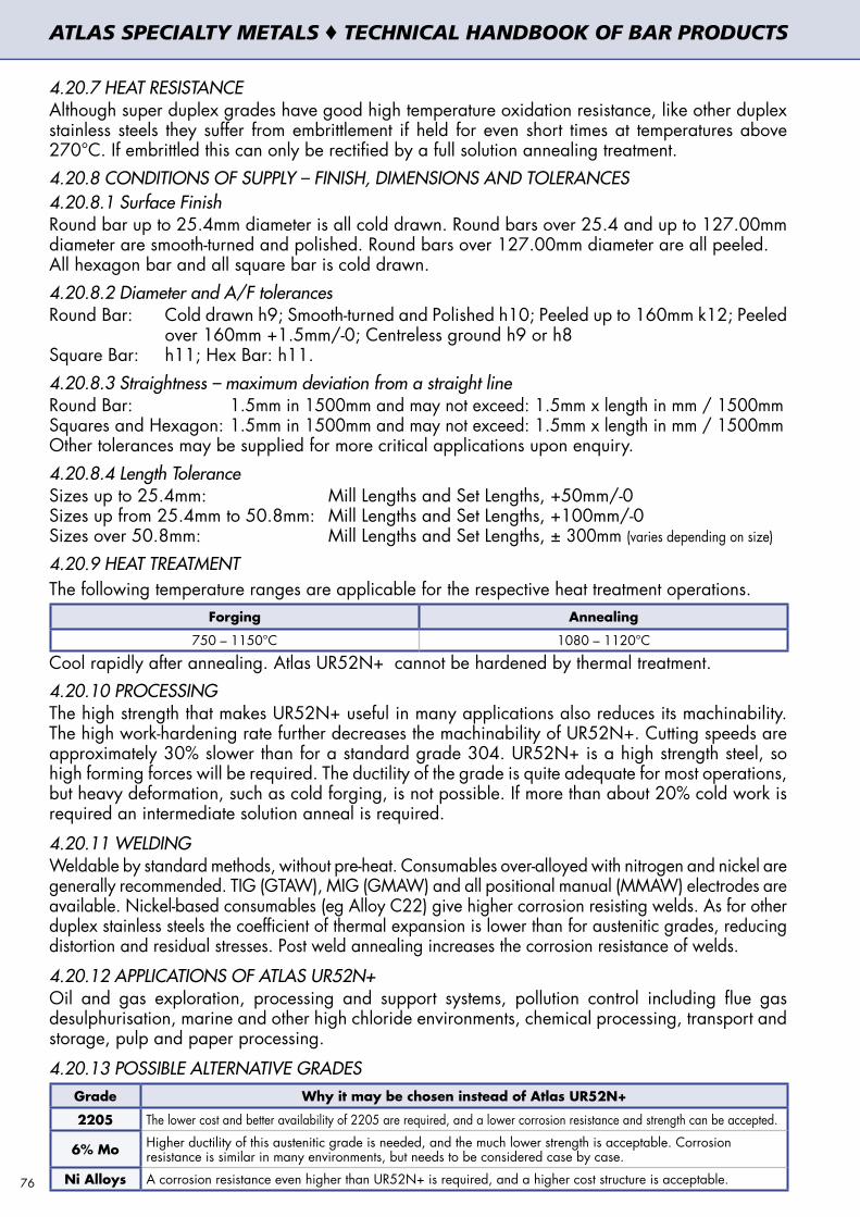
4.20.7 HEAT RESISTANCEAlthough super duplex grades have good high temperature oxidation resistance, like other duplex stainless steels they suffer from embrittlement if held for even short times at temperatures above 270°C. If embrittled this can only be rectified by a full solution annealing treatment. 4.20.8 CONDITIONS OF SUPPLY – FINISH, DIMENSIONS AND TOLERANCES4.20.8.1 Surface Finish Round bar up to 25.4mm diameter is all cold drawn. Round bars over 25.4 and up to 127.00mm diameter are smooth-turned and polished. Round bars over 127.00mm diameter are all peeled. All hexagon bar and all square bar is cold drawn. 4.20.8.2 Diameter and A/F tolerances Round Bar: Cold drawn h9; Smooth-turned and Polished h10; Peeled up to 160mm k12; Peeled
over 160mm +1.5mm/-0; Centreless ground h9 or h8Square Bar: h11; Hex Bar: h11.4.20.8.3 Straightness – maximum deviation from a straight lineRound Bar: 1.5mm in 1500mm and may not exceed: 1.5mm x length in mm / 1500mm Squares and Hexagon: 1.5mm in 1500mm and may not exceed: 1.5mm x length in mm / 1500mmOther tolerances may be supplied for more critical applications upon enquiry.4.20.8.4 Length Tolerance Sizes up to 25.4mm: Mill Lengths and Set Lengths, +50mm/-0Sizes up from 25.4mm to 50.8mm: Mill Lengths and Set Lengths, +100mm/-0Sizes over 50.8mm: Mill Lengths and Set Lengths, ± 300mm (varies depending on size)
4.20.9 HEAT TREATMENTThe following temperature ranges are applicable for the respective heat treatment operations.
Forging Annealing
750 – 1150°C 1080 – 1120°C
Cool rapidly after annealing. Atlas UR52N+ cannot be hardened by thermal treatment. 4.20.10 PROCESSINGThe high strength that makes UR52N+ useful in many applications also reduces its machinability. The high work-hardening rate further decreases the machinability of UR52N+. Cutting speeds are approximately 30% slower than for a standard grade 304. UR52N+ is a high strength steel, so high forming forces will be required. The ductility of the grade is quite adequate for most operations, but heavy deformation, such as cold forging, is not possible. If more than about 20% cold work is required an intermediate solution anneal is required.
4.20.11 WELDINGWeldable by standard methods, without pre-heat. Consumables over-alloyed with nitrogen and nickel are generally recommended. TIG (GTAW), MIG (GMAW) and all positional manual (MMAW) electrodes are available. Nickel-based consumables (eg Alloy C22) give higher corrosion resisting welds. As for other duplex stainless steels the coefficient of thermal expansion is lower than for austenitic grades, reducing distortion and residual stresses. Post weld annealing increases the corrosion resistance of welds.
4.20.12 APPLICATIONS OF ATLAS UR52N+Oil and gas exploration, processing and support systems, pollution control including flue gas desulphurisation, marine and other high chloride environments, chemical processing, transport and storage, pulp and paper processing.
4.20.13 POSSIBLE ALTERNATIVE GRADESGrade Why it may be chosen instead of Atlas UR52N+
2205 The lower cost and better availability of 2205 are required, and a lower corrosion resistance and strength can be accepted.
6% Mo Higher ductility of this austenitic grade is needed, and the much lower strength is acceptable. Corrosion resistance is similar in many environments, but needs to be considered case by case.
Ni Alloys A corrosion resistance even higher than UR52N+ is required, and a higher cost structure is acceptable.76
ATLAS SPECIALTY METALS ♦ TECHNICAL HANDBOOK OF BAR PRODUCTS

4.21 ATLAS 2011: ALUMINIUM MACHINING BAR
4.21.1 INTRODUCTION
Atlas 2011 is an aluminium alloy designed for high-speed machining with highest chipability of all aluminium alloys due to the addition of lead and bismuth. 2011 can be hard anodised but is not recommended for decorative anodising. Alloy 2011 is interchangeable with alloys 2017 and 2030. Alloy 2011 is heat treatable and has a high fatigue strength.
4.21.2 RELATED SPECIFICATIONS
Alloy UNS No AS 1865 / 1866
Euronorm 754 / 755 ASTM B211 / B221No Name
2011 A92011 2011 3.1655 EN AW-2011 / AlCu6BiPb 2011
These comparisons are approximate only. The list is intended as a comparison of functionally similar materials not as a schedule of contractual equivalents. If exact equivalents are needed original specifications must be consulted.
4.21.3 CHEMICAL COMPOSITIONSpecification values in %, according to AS1865/1866
Alloy 2011 Si Fe Cu Zn Pb Bi Others
min 5.0 0.2 0.2 each ≤ 0.05, total ≤ 0.15
max 0.4 0.7 6.0 0.30 0.6 0.6 each ≤ 0.05, total ≤ 0.15
4.21.4 TEMPER DESIGNATIONS AND DEFINITIONS
Product Temper Designation Definition
2011 Cold drawn
T3 Solution heat-treated, cold worked and naturally aged
T8Solution heat-treated, cold worked and artificially aged to
improve mechanical properties
2011 Extruded T6 Solution heat-treated and artificially aged
Atlas 2011 is stocked cold-drawn in temper T8 for sizes 5 – 9 mm diameter.Atlas 2011 is stocked cold-drawn in temper T3 for sizes 10 – 55 mm diameter.Atlas 2011 is stocked extruded in temper T6 for sizes over 55mm diameter.
4.21.5 SPECIFIED MECHANICAL PROPERTIES
Temper Size range Tensile Strength (MPa) min
0.2% Proof Stress (MPa) min
Elongation (% in 50mm) min
Typical Hardness (HB)
T3
> 5 ≤ 40mm 320 270 10 115
> 40 ≤ 50mm 300 250 10 110
> 50 ≤ 55mm 290 210 10 110
T6> 55 ≤ 125mm 310 230 8 110
>125 ≤ 200mm 295 195 6 110
Tensile strength, proof stress and elongation are guaranteed values as specified by EN 754-2 for cold drawn bar, resp. EN 755-2 for extruded bar. The requirements as per AS1865/1866 are within the limits of EN 754/755. Typical hardness is quoted for indication purposes only.
77
ATLAS SPECIALTY METALS ♦ TECHNICAL HANDBOOK OF BAR PRODUCTS

4.21.6 TYPICAL PHYSICAL PROPERTIES
Temper Density (kg/m³)
Elastic Modulus
(GPa)
Mean Coefficient of Thermal Expansion (mm/m/°C)
Thermal Conductivity
(W/m·K)
Specific Heat (J/kg·K)
Electrical Resistivity
(nΩ·m)
T3 2840 72.5 23 152 863 44
T6 2840 72.5 23 172 863 38
4.21.7 CORROSION RESISTANCE AND ANODISING
Atlas 2011 is generally not recommended for applications involving corrosion without hard or protective anodising. Corrosion performance in rural atmosphere is acceptable. Resistance to exfoliation corrosion is acceptable for T3 and good T6.Atlas 2011 is not recommended for bright or colour anodising. The product is suitable for protective anodising and performs well with hard anodising.
4.21.8 CONDITIONS OF SUPPLY – FINISH, DIMENSIONS AND TOLERANCES
4.21.8.1 Surface Finish Bars up to 55mm diameter are cold drawn. Bars with greater diameters are extruded.
4.21.8.2 Diameter and A/F tolerances Product Temper Range Tolerance
Round bar
T3
> 6 ≤ 10mm -0.09/+nil
> 10 ≤ 18mm -0.11/+nil
> 18 ≤ 30mm -0.13/+nil
> 30 ≤ 50mm -0.16/+nil
> 50 ≤ 55mm -0.19/+nil
T6
> 55 ≤ 65mm ± 0.40
> 65 ≤ 80mm ± 0.45
> 80 ≤ 100mm ± 0.55
>100 ≤ 120mm ± 0.65
>120 ≤ 150mm ± 0.80
>150 ≤ 180mm ± 1.00
>180 ≤ 220mm ± 1.15
Hexagonal bar T3
> 6 ≤ 10mm -0.09/+nil
>10 ≤ 18mm -0.11/+nil
>18 ≤ 30mm -0.13/+nil
>30 ≤ 50mm -0.16/+nil
Square bar
T3
> 6 ≤ 10mm -0.09/+nil
> 10 ≤ 18mm -0.11/+nil
> 18 ≤ 30mm -0.13/+nil
> 30 ≤ 50mm -0.16/+nil
> 50 ≤ 55mm -0.19/+nil
T6
> 55 ≤ 65mm ± 0.50
> 65 ≤ 80mm ± 0.70
> 80 ≤ 100mm ± 0.90
>100 ≤ 120mm ± 1.00
4.21.8.3 Straightness – maximum deviation from a straight line
Round, square and hexagonal cold-drawn bar and extruded bar up to 80mm: 0.6mm in any 300mm and may not exceed over total bar length: 2mm x length in metres.Round, square and hexagonal extruded bar over 80mm up to 120mm: 1.0mm in any 300mm and may not exceed over total bar length: 2mm x length in metres.Round, square and hexagonal extruded bar over 120mm up to 200mm: 1.5mm in any 300mm and may not exceed over total bar length: 3mm x length in metres.78
ATLAS SPECIALTY METALS ♦ TECHNICAL HANDBOOK OF BAR PRODUCTS

4.21.8.4 Length Tolerance
Round, square and hexagonal bar:
Size up to 55mm (drawn): ± 7mm for bar length up to 5000mmSize 60-100mm (extruded): + 7mm/-0 for bar length up to 5000mmSize 100-200mm (extruded): + 9mm/-0 for bar length up to 5000mm
4.21.9 WELDING AND COLD FORMING
Atlas 2011 is not suitable for welding processes such as oxy-gas welding, MIG/TIG welding or resistance welding. It cannot be brazed. It has acceptable soldering properties.Atlas 2011 is not recommended to undergo any cold forming operations.
4.21.10 APPLICATIONS OF ATLAS 2011
General components such as screws, bolts, fittings, nuts, automatic lathe products. Auto fuel systems, clock parts, gears and machine parts, pipe stems, TV fittings, camera parts, meter shafts, ordnance, industrial connectors. Applications where good machinability and strength are required.
4.21.11 POSSIBLE ALTERNATIVE ALLOYS
Alloys Why it may be chosen instead of Atlas 2011
2030 When free machining alloy is required and better mechanical properties are needed than 2011 offers.
6262When alloy is needed with good machinability and similar mechanical properties as 2011, but good corrosions resistance and/or anodising properties and/or weldability are required as well.
79
ATLAS SPECIALTY METALS ♦ TECHNICAL HANDBOOK OF BAR PRODUCTS

4.22 ATLAS 6262: ALUMINIUM MACHINING BAR4.22.1 INTRODUCTIONAtlas 6262 is an aluminium alloy designed for offering high machinability, good mechanical properties and high corrosion resistance. Machinability of 6262 is significantly higher than that of other 6000 series alloys like 6061 or 6082 and approaches the machinability of alloys like 2011 or 2030. Machined pieces easily obtain a smooth and bright finish. The mechanical, corrosion and anodising properties are comparable to alloy 6061 and alloy 6082. Atlas 6262 can be protective or hard anodised. It is also available in the 6262-ECO version with reduced lead content.
4.22.2 RELATED SPECIFICATIONS
Alloy UNS No AS 1865/1866Euronorm ASTM B211 /
B221No Name
6262 A96262 6262 EN AW-6262 AlMg1SiPb 6262
These comparisons are approximate only. The list is intended as a comparison of functionally similar materials not as a schedule of contractual equivalents. If exact equivalents are needed original specifications must be consulted.
4.22.3 CHEMICAL COMPOSITIONSpecification values in %, according to AS1865/1866Alloy 6262 Si Fe Cu Mn Mg Cr Zn Ti Pb Bi Others
Min 0.4 0.15 0.8 0.04 0.4 0.4 each ≤ 0.05, total ≤ 0.15
Max 0.8 0.7 0.40 0.15 1.2 0.14 0.25 0.15 0.7 0.7 each ≤ 0.05, total ≤ 0.15
Alloy 6262-ECO Si Fe Cu Mn Mg Cr Zn Ti Pb Bi Others
Min 0.6 0.2 0.6 0.4 each ≤ 0.05, total ≤ 0.15
Max 1.4 0.7 0.50 1.2 1.2 0.30 0.30 0.20 0.4 2.0 each ≤ 0.05, total ≤ 0.15
There is no difference in the mechanical properties, corrosion resistance, anodising properties and weldability of Atlas 6262 and Atlas 6262-ECO. The machinability of Atlas 6262-ECO is slightly better than that of Atlas 6262.
4.22.4 TEMPER DESIGNATIONS AND DEFINITIONSProduct Temper Designation Definition
6262 Cold drawn
T9 Solution heat-treated, artificially aged and cold worked
T91 Solution heat-treated, artificially aged and cold worked
T8 Solution heat-treated, cold worked and artificially aged
6262 Extruded T6 Solution heat-treated and artificially aged
Atlas 6262/6262-ECO is stocked in temper T9 for sizes 5 – 55mm diameter.Atlas 6262/6262-ECO is stocked in temper T6 for sizes over 55mm diameter.
4.22.5 SPECIFIED MECHANICAL PROPERTIES FOR ATLAS 6262 AND ATLAS 6262-ECOTensile strength, proof stress and elongation are guaranteed values as specified by EN 754-2 (drawn bar) and EN 755-2 (extruded bar). Typical hardness is quoted for indication purposes only. The mechanical properties as required by AS1865/1866 are within the limits of EN 754/755.
Temper Size range Tensile Strength (MPa) min
0.2% Proof Stress (MPa) min
Elongation (% in 50mm) min Typical Hardness (HB)
T9 > 5 ≤ 50mm 360 330 4 110
T9 > 50 ≤ 55mm 345 310 4
T6 > 55mm 260 240 8
4.22.6 TYPICAL PHYSICAL PROPERTIES
Temper Density (kg/m³)
Elastic Mod-ulus (GPa)
Mean Coefficient of Thermal Expansion (mm/m/°C)
Thermal Cond-uctivity (W/m·K)
Specific Heat (J/kg·K)
Electrical Resi -stivity (nΩ·m)
T9 2840 69.0 23.4 172 825 39
T6 2840 69.0 23.4 82580
ATLAS SPECIALTY METALS ♦ TECHNICAL HANDBOOK OF BAR PRODUCTS

4.22.7 CORROSION RESISTANCE AND ANODISINGAtlas 6262 is one of the most corrosion resistant aluminium alloys. Susceptibility to stress-corrosion cracking and exfoliation is negligible. Galvanic corrosion can occur in the course of direct contact with dissimilar metals and this should therefore be avoided. It has acceptable corrosion-resistance performance in marine environments too. Atlas 6262 is excellent for protective anodising, whilst it has good properties for hard and decorative anodising.
4.22.8 CONDITIONS OF SUPPLY – FINISH, DIMENSIONS AND TOLERANCES4.22.8.1 Surface Finish Bars up to 55mm diameter are cold drawn. Bars with greater diameters are extruded.4.22.8.2 Diameter and A/F tolerances
Product Temper Range Tolerance
Round bar
T9
> 6 ≤ 10mm -0.09/+nil
> 10 ≤ 18mm -0.11/+nil
> 18 ≤ 30mm -0.13/+nil
> 30 ≤ 50mm -0.16/+nil
> 50 ≤ 55mm -0.19/+nil
T6
> 55 ≤ 65mm ± 0.40
> 65 ≤ 80mm ± 0.45
> 80 ≤ 100mm ± 0.55
>100 ≤ 120mm ± 0.65
>120 ≤ 150mm ± 0.80
>150 ≤ 180mm ± 1.00
>180 ≤ 220mm ± 1.15
Hexagonal bar T9
> 6 ≤ 10mm -0.09/+nil
> 10 ≤ 18mm -0.11/+nil
> 18 ≤ 30mm -0.13/+nil
> 30 ≤ 50mm -0.16/+nil
Square bar
T9
> 6 ≤ 10mm -0.09/+nil
> 10 ≤ 18mm -0.11/+nil
> 18 ≤ 30mm -0.13/+nil
> 30 ≤ 50mm -0.16/+nil
> 50 ≤ 55mm -0.19/+nil
T6
> 55 ≤ 65mm ± 0.50
> 65 ≤ 80mm ± 0.70
> 80 ≤ 100mm ± 0.90
>100 ≤ 120mm ± 1.00
4.22.8.3 Straightness – maximum deviation from a straight lineRound, square and hexagonal bar: 0.6mm in any 300mm and may not exceed over total bar length: 0.7mm x length in metres.4.22.8.4 Length Tolerance Round, square and hexagonal bar:Diameter up to 55mm (drawn): ± 3mm for bar length up to 4000mmDiameter 60-75mm (extruded): + 3mm/-0 for bar length up to 4000mmDiameter over 75mm (extruded): + 5mm/-0 for bar length up to 4000mm
4.22.9 WELDING AND COLD FORMINGAtlas 6262 has excellent weldability and is suitable for all conventional welding processes. Best results are achieved with MIG, TIG or resistance welding. It can be brazed very well.
4.22.10 APPLICATIONS OF ATLAS 6262General components for automotive industry, such as transmission valves, brake pistons or air conditioners, CATV connectors, camera parts, tripod fittings.
4.22.11 POSSIBLE ALTERNATIVE GRADESGrade Why it may be chosen instead of Atlas 6262
6082 When machining properties can be sacrificed in return for further improved corrosion resistance
2011 When alloy is needed with even better machinability and similar mechanical properties as 6262, and sacrifices are possible in corrosion resistance and/or anodising properties and/or weldability. 81
ATLAS SPECIALTY METALS ♦ TECHNICAL HANDBOOK OF BAR PRODUCTS


5. NON-DESTRUCTIVE TESTING OF ATLAS BAR PRODUCTS5. NON-DESTRUCTIVE TESTING OF ATLAS BAR PRODUCTS
5.1 HOW DOES ULTRASONIC INSPECTION WORK?
Ultrasonic inspection normally involves the use of a piezo electric transducer which is both a transmitter and receiver of ultrasound. The transducer must be coupled to the item to be inspected, as ultrasound at the frequency used is not transmitted in air. Coupling of the transducer to the item under inspection may be achieved in two main ways: In the case of the contact inspection method a coupling medium (oil or wall paper paste, or similar) is used. The other common process used is immersion testing where the component or material under inspection is immersed in a water bath and ultrasound is transmitted through the water and into the component. (Corrosion inhibitors are normally added to the water bath where immersion testing is involved).
Illustration of ultrasonic detection ofimpurities in a steel bar
Back wall
Defect
Back Wall EchoInitialPulse
Flaw Echo
Back Wall EchoInitialPulse
Flaw Echo


A proportion of the ultrasound is reflected back at interfaces such as the coupling medium / material interface, but the majority of the ultrasound should ideally be transmitted into the material / steel under inspection. Ultrasound is reflected from the back surface (back wall) of the item under inspection and off any planar discontinuities that may be present in the steel. (Note: to be able to detect any the discontinuities present in the steel matrix the acoustic properties of the discontinuity must be different to those of the defect free steel). The transducer (as described above) comprises of a piezo electric crystal. Initially, the piezo crystal converts electrical energy to ultrasound which is transmitted into the item under inspection. Ultrasound reflected back to the crystal is then converted to electrical energy and this signal is amplified, and in turn the signal is monitored on a cathode ray tube or digital display screen. The time base can be calibrated providing information on the location of defects in relation to their position between the front and back wall of the item under inspection. Also using relative reflectivity (at known gain setting and beam path lengths) it is possible to determine the size of discontinuities present. An experienced ultrasonic technician can accurately map the location, size and shape of discontinuities that may be present. Based on the location, size, shape / geometry of a discontinuity it may then be categorised as a defectAn analogy is sometimes used to help describe the ultrasonic test method. Imagine being in a darkened room and a torch light producing a diverging beam of light is allowed to shine on a sheet of A4 paper. Where the sheet of paper is presented at right angles to the diverging beam of light more light energy is reflected backwards. If on the other hand the sheet of paper is placed in the light beam and placed parallel to the diverging beam of light (i.e. edge on) then very little light is reflected backwards. Similar principles apply to ultrasonic testing in that a diverging beam of ultrasound is used and discontinuities that present themselves at right angles to the ultrasonic beam may be detected (assuming a large enough reflectivity applies), while those that present themselves with their plane parallel to the ultrasonic beam are very difficult or impossible to detect.Therefore, scanning methods may involve the use of normal and / or shear wave probes. A normal “0°” probe essentially directs ultrasound into the component under inspection normal to the surface (i.e. at right angles to the surface). A shear wave probe on the other hand directs ultrasound into the component at an angle. Common angles might be in the range 30° through to around 60°. Ultrasound may be diffracted and bent as it moves between material having differing acoustic attenuations, (this is similar to light through a prism). Also ultrasound changes velocity depending on the material through which it is travelling. The formula V=fl, where V=velocity, f = frequency and l = wavelength may be used by an ultrasonic technician. Ultrasonic probes are normally identified with the following basic information: Frequency (MHz), Diameter and Angle. Please note that the information provided above is not meant to be exhaustive, rather it is an introduction to the some of the major principles of the ultrasonic test method.
5.2 WHY IS ULTRASONIC INSPECTION AN ISSUE?
All rolled and forged steel products contain microscopic discontinuities, such as non-metallic inclusions. Volumetric discontinuities such as voids or cavities may also be present, originating from shrinkage or gas porosity. In addition, surface discontinuities or defects such as cracks or seams may be present, remnant from hot processing of billets or created during heat treatment.The issue is: when does a discontinuity become a defect? Discontinuity size and shape, frequency of occurrence, distribution and location all need to be considered. Rejection or acceptance of discontinuities also depends on the application of the component. The loss of effective cross-section due to the presence of any discontinuity, loss of strength due to fatigue, and implications of sudden impact are all relevant considerations.Ultrasonic inspection is a non-destructive testing method used to locate volumetric discontinuities and to determine their size, geometry and frequency of occurrence.
ATLAS SPECIALTY METALS ♦ TECHNICAL HANDBOOK OF BAR PRODUCTS
85

5.3 ULTRASONIC INSPECTION OF ATLAS ALLOY BAR
Products benefiting from inspection: Atlas 4140, Atlas 4340, Atlas 6582, Atlas 6580, Atlas 6587, Atlas 6657 and Atlas 8620H.
5.3.1 WHAT DOES IT MEAN?
All alloy steel bar products that are sold from Atlas stock are ultrasonic inspected. Ultrasonic inspection has been performed in accordance with a defined standard. The inspection standard is explicit and transparent: AS 1065 to Level 2. AS1065 is the Australian Standard for “Non-Destructive Testing of Carbon and Low Alloy
Steel Forgings”. Level 2 refers to the precise inspection criteria.
5.3.2 WHY AS1065 LEVEL 2?
AS1065 defines the method of ultrasonic inspection. There are three inspection levels. The higher the level (i.e. Level 1 is higher than Level 2 which in turn is higher than Level 3), the lower the frequency and the smaller the size of the discontinuities allowed to be found by the ultrasonic inspection.If a product meets AS1065 Level 2 it will be suitable for most general engineering applications. A small number of applications will call for an even more stringent specification regarding ultrasonic inspection; this can be carried out if requested.
5.3.3 WHAT ARE THE BENEFITS TO THE CUSTOMER?
End user Quality of the Product is Guaranteed. Mill certificate based on test results is available, which can be submitted to the end user. The
mill certificate will state the Ultrasonic Test Method and Acceptance Criteria used. Reduction in the likelihood of incurring costs and loss of time where defects are found to be
present at the time of machining. Reduction in the likelihood of production time losses and the associated costs if a component
fails in service.
••••
•
••
•
•
ATLAS SPECIALTY METALS ♦ TECHNICAL HANDBOOK OF BAR PRODUCTS
86

6. HEAT AND SURFACE TREATMENT OF STEELS6. HEAT AND SURFACE TREATMENT OF STEELS 7. MACHINABILITY AND MACHINABILITY DATASHEETS7. MACHINABILITY AND MACHINABILITY DATASHEETS


A large variety of heat treatments can be applied to steels - this feature is one of the reasons that steels are such versatile engineering materials. The most common heat treatments are:
6.1 AS ROLLED & AS FORGED
Steel produced by hot rolling, and allowed to cool from the rolling temperature without strict control. No separate heat treatment operation is applied, but this approximates a normalised condition. Bars larger than about 250mm (it varies between steel mills) cannot be hot rolled to final size; these are hot forged in a large forging press. Again the bars are shipped without subsequent heat treatment. This condition is only used for steels destined for fairly non-critical applications.
6.2 ANNEALING
Full annealing:
- consists of heating the steel to its austenitizing temperature (approx 890°C for 0.2% carbon steel, and 840°C for 0.4% carbon), holding it until temperature uniformity is achieved, and then cooling slowly to a low temperature. The cooling rate is most critical through the transformation range (around 850°C for a 0.2% carbon steel, and 815°C for 0.4%C). Cooling is usually in the furnace and so the heat treatment cycle time is quite long.
Sub-critical annealing: - (or stress-relief annealing) uses a lower temperature (typically 550 – 650°C) and shorter cycle time. This operation is used when the heat treated component does not have to be in softest condition. This treatment is to remove residual stresses remnant from heavy machining or other cold work.
Spheroidise annealing: - is a treatment where the steel is held just below the lower critical temperature (around 700°C) for a prolonged period, or alternatively heated and cooled to just above and just below the lower critical temperature. This treatment is only used for steels requiring maximum ductility, such as those for cold heading to make bolts.
Solution Treatment: - The annealing process carried out on austenitic stainless steels; solution of all phases in the material at a very high temperature (generally about 1050°C), followed by rapid cooling to prevent precipitation.
Stabilisation Treatment: - is an optional secondary treatment of stabilised austenitic stainless steels (grades 321, 347 and 316Ti) to ensure all carbon is precipitated as titanium or niobium carbides. The temperature is about 820 – 900°C.
6.3 NORMALISING
Normalising is achieved by heating to a slightly higher temperature than annealing, and then cooling a little quicker - generally in still air. The microstructure produced is a fine, fairly soft structure of pearlite, and (depending upon carbon content) probably some ferrite. The result is a slightly stronger and harder steel compared with the annealed alternative. In low carbon steels normalising also results in a better machining steel compared with annealed.
ATLAS SPECIALTY METALS ♦ TECHNICAL HANDBOOK OF BAR PRODUCTS
89

6.4 HARDENING & TEMPERING
6.4.1 HARDENING
Hardening of steel is achieved by cooling quickly from the austenitising temperature (around 850°C – 900°C). At this temperature the structure of most a steels is pure austenite. Most steels transform to some other structure (or “phase”) when cooled from this temperature, depending upon the cooling rate, and it is these phase changes that generate the various heat treated conditions. Only austenitic stainless steels and austenitic manganese steels retain their austenitic structures when cooled down to room temperature. They cannot be hardened by quenching.
The result of fast quenching of low alloy steels is a metallurgical structure called martensite, a very hard but brittle phase. The hardness of a martensitic steel depends upon the alloy content – the most significant element is the carbon content, with higher carbon content steels being able to be made much harder, as shown in the graph below. Very low carbon martensites (less than about 0.1% C) are relatively low hardness and quite tough. It follows that mild steel, or other low carbon steels, cannot be hardened to high hardnesses. A medium carbon steel such as 4140 results in a hardness of up to about Rockwell C 60 (60 HRC) in the fully hardened condition. Higher carbon contents – up to about 1.0% C will result in as-quenched hardnesses of up to about 70 HRC. Cutting and metal working tools are almost always made from high carbon steels, so that the required high hardness can be achieved in heat treatment.
The cooling (also called “quenching”) is carried out in various cooling media, with various cooling rates achievable. Quenching into brine (salty water) results in a very fast cool, plain fresh water gives a slightly slower cooling rate, and quenching into oil gives a slower rate again. Simply removing the hot steel from the furnace and cooling it by blowing air past it is slower still. A polymer quench is a synthetic water mix, with various cooling rates available.
“Hardenability” is the ability of a steel to be hardened through a section thickness. The graph above assumes that the resulting microstructure is 100% martensite, but for each steel composition there is a critical cooling rate which must be achieved if the structure is to be fully martensitic.
0
10
20
30
40
50
60
70
80
0.00 0.20 0.40 0.60 0.80 1.00 1.20
Hardness of Martensite
Roc
kw
ell H
ard
ness
C
Carbon (%)
90
ATLAS SPECIALTY METALS ♦ TECHNICAL HANDBOOK OF BAR PRODUCTS
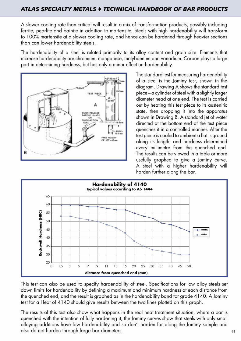
A slower cooling rate than critical will result in a mix of transformation products, possibly including ferrite, pearlite and bainite in addition to martensite. Steels with high hardenability will transform to 100% martensite at a slower cooling rate, and hence can be hardened through heavier sections than can lower hardenability steels.
The hardenability of a steel is related primarily to its alloy content and grain size. Elements that increase hardenability are chromium, manganese, molybdenum and vanadium. Carbon plays a large part in determining hardness, but has only a minor effect on hardenability.
The standard test for measuring hardenability of a steel is the Jominy test, shown in the diagram. Drawing A shows the standard test piece – a cylinder of steel with a slightly larger diameter head at one end. The test is carried out by heating this test piece to its austenitic state, then dropping it into the apparatus shown in Drawing B. A standard jet of water directed at the bottom end of the test piece quenches it in a controlled manner. After the test piece is cooled to ambient a flat is ground along its length, and hardness determined every millimetre from the quenched end. The results can be viewed in a table or more usefully graphed to give a Jominy curve. A steel with a higher hardenability will harden further along the bar.
This test can also be used to specify hardenability of steel. Specifications for low alloy steels set down limits for hardenability by defining a maximum and minimum hardness at each distance from the quenched end, and the result is graphed as in the hardenability band for grade 4140. A Jominy test for a Heat of 4140 should give results between the two lines plotted on this graph.
The results of this test also show what happens in the real heat treatment situation, where a bar is quenched with the intention of fully hardening it; the Jominy curves show that steels with only small alloying additions have low hardenability and so don’t harden far along the Jominy sample and also do not harden through large bar diameters.
Roc
kw
ell H
ard
ness
(H
RC)
Hardenability of 4140Typical values according to AS 1444
max
min
distance from quenched end (mm)
25
30
35
40
45
50
55
60
65
0 1.5 3 5 7 9 11 13 15 20 25 30 35 40 45 50
91
ATLAS SPECIALTY METALS ♦ TECHNICAL HANDBOOK OF BAR PRODUCTS

6.4.2 TEMPERINGAlthough as-quenched martensite is hard it is also quite brittle. The brittleness can be reduced (and toughness increased) by “tempering” - a second heat treatment involving heating the hardened steel to an intermediate temperature. This results in a trade-off between strength and toughness. Tempering is almost always an essential second step … as-quenched martensite is usually too brittle for practical service applications. The response of a quenched (fully martensitic) steel to tempering is quite predictable; the higher the tempering temperature the more the hardness, tensile strength and proof stress are reduced, and the more the toughness (impact), elongation and reduction of area properties are increased. A tempering curve for low alloy steel 4140 is shown below.
This diagram indicates the typical mechanical properties (tensile strength, yield point or proof stress, elongation, reduction of area and Izod or Charpy impact resistance) to be expected when the steel is quenched from the correct hardening temperature and then tempered at the nominated temperature. This diagram is typical for grade 4140, but compositional variations between individual heats will have some influence on the outcome. Other conditions such as hardening (austenitising) time and temperature and sample size also have an influence on the properties of the tempered product. For many steels (including 4140) there is a substantial drop in Izod impact strength in the range 200 to 450°C so this tempering range is usually avoided.
This data assumes that the steel is fully hardened, i.e. that it was quenched in the hardening heat treatment sufficiently fast that the structure was converted to martensite right through to the centre. A steel which is not cooled sufficiently fast transforms to some other products, in addition to martensite, towards the bar centre. Such a structure is said to be “slack quenched”, and although it may exhibit the same strength or hardness as a correctly hardened and tempered structure its toughness and ductility will be inferior. If the component being produced is not able to be fully hardened through the required section thickness, then another steel grade, with higher hardenability, should usually be selected.
600
800
1000
1200
1400
1600
400 500 600 7000
10
20
30
40
50
60
70
80
90
100
ProofStress Reduction
of Area
Elongation
∞Tempering Temp ( C)
Izodimpact
TensileStrength
Elon
gatio
n (A
%),
Red
uctio
n of
Are
a (
Z%
)and
Izod
Impact
(J)
Tens
ile S
tren
gth
and
0.2
% P
roof
Str
ess
(MPa
)
Tempering Diagram 4140typical values for 30mm section
92
ATLAS SPECIALTY METALS ♦ TECHNICAL HANDBOOK OF BAR PRODUCTS

6.5 SURFACE HARDENING OF STEELS
A good combination for many high duty engineering components is a hard outside skin (case) while still retaining a slightly softer, tougher inside (core). One of the main benefits of steel as an engineering material is its capacity for surface hardening to give this combination of desirable properties.
Induction and flame hardening of medium carbon steels are selective surface hardening processes that result in a localised harden-and-temper; heat input is restricted to just the outer layer of the steel. There is no change to the composition and no diffusion required. The processes can therefore be very rapid.
Case hardening by contrast is a group of diffusion-based operations that change the composition of the external component layer. Steels subjected to carburising, nitriding or similar processes have increased carbon or nitrogen in their surfaces, and in fact are different steels at the surface compared to the underlying core.
6.6 CASE HARDENING - CARBURISING
The hardness achievable by hardening and tempering a steel is very largely determined by its carbon content (see previous graph). One way of achieving this mixture of properties is therefore to add carbon to the case, usually by putting the steel in a furnace containing a high carbon content gas, and then to harden and temper the component. The two operations – carburising and hardening & tempering – should be seen as distinct, although in some instances the heat treatment is carried out directly from the carburising temperature. Very high surface hardnesses (in excess of 60 HRC) can be achieved by this carburising treatment.
This treatment is very widely used for gears. Steels used have low carbon content (typically 0.15 - 0.20%), and medium to high alloy content (eg Atlas 6587, 6657, 8620, En36A, En39B).
Carburising of the steel surface is most commonly carried out by pack or gas processes, although liquid (salt bath), vacuum and plasma processes are also used. In any carburisation process the aim is to drive carbon into the surface of a steel with originally a low carbon content, usually less than 0.25%, and to increase this to approximately 0.8 – 1.0% at the surface. The depth of this carburised layer will depend upon the temperature, time of carburising, type of carburising cycle, carbon concentration at the surface of the specimen and original composition of the steel. This is a diffusion process, driven by concentration differences and very much time dependent. The processes achieve a thin carburised layer very quickly, but because diffusion is the controlling mechanism it becomes increasingly slow to achieve deeper cases.
6.6.1 PACK CARBURISINGIn this process, the part that is to be carburised is packed in a steel container so that it is completely surrounded by granules of charcoal. The charcoal is treated with an activating chemical such as barium carbonate that promotes the formation of carbon dioxide. This gas in turn reacts with the excess carbon in the charcoal to produce carbon monoxide, which reacts with the low-carbon steel surface to form atomic carbon, able to diffuse into the steel. This carburising process does not harden the steel, it only increases the carbon content to some depth below the surface, so that when subsequent quenching is carried out the surface will achieve a high hardness.
It is difficult to quench components directly from the pack, as the sealed container has to be opened and the parts extracted. It is more usual to slow cool the entire pack at the end of the carburisation time and remove the part for separate hardening and tempering. This technique lends itself to jobbing work, requires only basic heat treatment equipment and can carburise to a depth of up to about 1.3mm. It is unsuitable for continuous production work, or for thin or closely controlled case depths.
93
ATLAS SPECIALTY METALS ♦ TECHNICAL HANDBOOK OF BAR PRODUCTS
6.6.2 GAS CARBURISINGThis process is commonly used for production carburising, and is well suited to continuous furnace lines. The components are heated above the upper critical temperature (Ac3) in a furnace with an atmosphere of carbon-containing gas such as methane, ethane, propane, natural gas, acetylene, manufactured gas or mixed hydrocarbon gases. Most carburising gases are flammable and controls are needed to keep this carburising gas at approximately 925°C from contacting oxygen. The carburising gases are often diluted with an endothermic carrier gas, mainly nitrogen and carbon monoxide along with smaller amounts of carbon dioxide, hydrogen and water vapour. The carrier gas serves to control the amount of carbon supplied to the steel surface and prevents the formation of soot residue. Control of the process is often by measurement of the dew point, related to the water vapour content of the gas mixture.
As for pack carburising, the carbon monoxide (dissociated from the carbon-containing gas such as methane) decomposes to atomic carbon which is able to diffuse into the steel.
Gas carburising allows more accurate control of the composition and depth of the case than does pack carburising, and is more suited to continuous production. The equipment required however is more sophisticated and specialised, and requires highly skilled operators. There are also safety issues associated with the carburising gases – these can be explosive mixtures.
6.6.3 CARBURISING – HEAT TREATMENTThe second step of the case hardening process is heat treatment – a harden-and-temper operation designed to produce the desired combination of properties in both the case and core.
Because the case and core have widely different carbon contents, they also have different austenitising (“Ac3”) temperatures for hardening – ideally about 880°C for the core and 760°C for the case. The ideal treatment is firstly to heat the steel to grain refine the core, followed by a water quench and then a second heating to about 760°C followed by a second quench. The result of this treatment is a case of fine-grained martensite surrounding a core of fine ferrite and bainite. A final low temperature temper (160 – 220°C) will relieve any quenching stresses in the case.
A more economical heat treatment cycle is so-called direct hardening. This is particularly appropriate for thin cases (up to 0.5mm) because the relatively short carburising time will not have produced excessive grain growth. Here the components are quenched directly from the end of the carburisation treatment, followed only by the temper.
An intermediate approach, suitable for intermediate depth cases, is to cool slowly from the carburising temperature and then to re-heat to a compromise temperature of around 820°C, followed by a water quench and then temper. This treatment results in slightly coarse-grained case and core, but the properties are satisfactory for many applications.
6.7 NITRIDING
In this process atomic nitrogen is diffused into the steel surface, similar to the carbon diffusion of carburising. The treatment temperature is much lower than for carburising, in the range 500 – 600°C, but for generally longer times – up to 100 hours, depending on the steel being treated and the desired case depth. Under these conditions very hard nitrides form at and near the steel surface. Steels suitable for nitriding contain the nitride-forming elements aluminium, chromium, molybdenum or vanadium. Steels containing aluminium will form very hard but thin cases, while those with chromium will form slightly softer and deeper nitrided cases. Plain carbon steels do not respond well to nitriding.
As the nitriding temperature is comparatively low this treatment results in less distortion, and volume changes are low because there is no phase transformation. The normal process is to harden and temper the component first to achieve the required core properties, followed by machining and finally nitriding.
94
ATLAS SPECIALTY METALS ♦ TECHNICAL HANDBOOK OF BAR PRODUCTS

Gas nitriding is usually carried out in an atmosphere of ammonia, which dissociates to nitrogen and hydrogen at the treatment temperature. Over-nitriding results in a thick layer of iron nitrides on the steel surface – called the “white layer” because of its appearance through a microscope. The white layer has a detrimental effect on fatigue life so is usually either removed or the nitriding process controlled to prevent its formation. Some proprietary nitriding processes have become available, offering precise control over case depth and hardness and freedom from white layer.
6.7.1 CARBONITRIDINGThis process involves the diffusion of both carbon and nitrogen into a steel surface, so combines carburising and nitriding treatments. The process is performed in a gas furnace using a carburising gas such as propane or methane, mixed with several percent of ammonia, which is a source of nitrogen. The process is well suited to continuous furnace operation, and results in case hardnesses of 60 – 65 HRC and depths of about 0.08 – 0.8mm. Carbonitriding is performed at 700 – 800°C, followed by a quench into oil or by gas. Distortion is likely to be less than for carburisation but more than nitriding. Unlike nitriding this process can be applied to plain carbon steels.
6.8 SELECTIVE SURFACE HARDENING
These processes do not change the surface composition but are in fact heat treatments confined to local areas of the component. The surface – and usually only a small section of the component’s overall surface – is austenitised and then rapidly quenched to produce martensite. The basic requirement is that the steel have sufficient carbon and hardenability to achieve the required hardness at the surface. Medium carbon steels are usually used. The processes are classified according to heat source – the most commonly used are flame hardening and induction hardening, but there are also applications using lasers and electron beams. In addition to increased wear resistance the surface hardening also induces residual compressive stresses that result in improved bending and torsional strength as well as increased fatigue properties. The component is first hardened and tempered (or normalised) to achieve the required core properties, and the selected areas of the surface are then austenitised and quenched. The final result is a core structure of tempered martensite (or ferrite / pearlite if normalised) with a surface case of untempered martensite. The case is not as hard as in a carburised steel because the carbon content of the surface is not as high.
6.9 FLAME HARDENING
The selected surface area is quickly heated by a gas flame. When the outside layer is heated above its transformation temperature (austenitised) the component is quenched. The result is re-hardening of the outer surface. Manually operated torches are useful for small areas such as the cutting edge of a tool. The process can be automated for repetitive components, with torches arranged according to the component shape. Symmetrical parts such as gears and shafts can be spun between centres within a ring burner; the work piece rotates slowly and as soon as the surface has reached the required austenitic state it is quenched either by complete immersion or by water jets adjacent to the burner ring. Quenching of the surface layer is also assisted by “self quenching” – the inner core of the component remains cold throughout, and its mass will quickly conduct heat from the outer surface.
6.10 INDUCTION HARDENING
This process is the same as flame hardening except that an induction coil provides the heat to the steel surface. The pattern of the heated region can be very precisely controlled by the shape of the coil and also by the frequency of the alternating current in the coil; the higher the frequency the shallower is the depth of penetration of the heating. Induction heating is highly suited to large production runs of similar parts. Its advantages compared to flame hardening are rapid heating rate, less component scaling, high production rate, very precise control over hardening location and depth and low energy consumption.
95
ATLAS SPECIALTY METALS ♦ TECHNICAL HANDBOOK OF BAR PRODUCTS


6. HEAT AND SURFACE TREATMENT OF STEELS6. HEAT AND SURFACE TREATMENT OF STEELS 7. MACHINABILITY AND MACHINABILITY DATASHEETS7. MACHINABILITY AND MACHINABILITY DATASHEETS


7.1 MACHINING AND MACHINABILITY
In this section general guidelines are given for the machining of the bar product stocked and marketed by Atlas Specialty Metals. This concerns carbon and alloy steels (section 7.2), stainless steels (section 7.3) and aluminium alloys (section 7.4).
The term machinability includes all those properties which are relevant for the machining and cutting process:
• the wear of tools • the necessary cutting force • the resulting form of the chips • the quality of the surface produced
Machinability should not be regarded as a material property which can be expressed in a number or a single parameter. It is a very complex technological construct. The machinability depends both on the general physical and chemical properties of the material used, as well on the fabrication process used to produce the material itself, hence we talk about IM or improved machinability products that are produced in a way to make them more machinable.The parameters influencing machinability and the outcome of the machining process are shown in the figure below.
MACHINABILITY PARAMETERS
MACHINING INPUT PARAMETER CHIP FORM SURFACE WEAR CUTTING FORCE
PROCESS *** *** *** ***
MATERIAL *** ** *** **CUTTING PARAMETERS AND TOOL GEOMETRY ** *** *** **
MACHINE * *** ** *
TOOL MATERIAL * ** *** *
* = NOT SIGNIFICANT, ** = SIGNIFICANT, *** = VERY SIGNIFICANT
Process relates to the type of machining process (turning, milling, etc.) and the kinematical arrangement of the tools, this is the most important element governing the outcome of a machining operation. As mentioned, different materials vary in their machinability and the way they behave under different cutting conditions. For example, stainless steels should be machined with high feed rate and depth of cut in order to counter work-hardening that occurs. Aluminium alloys should generally be machined with maximised surface speed in order to counter the tendency for build-up on the cutting edge. Guidelines for “feeds and speeds” are given in the following sections. Tool materials should carefully selected, matching the material that is to be machined. Here again important differences exist between materials: coated carbide inserts work very well for carbon and stainless steels but are not recommended for aluminium, as titanium (coating layer usually being titanium nitride) has a chemical affinity for aluminium and will hence quickly dissipate and make the tool surface softer.
ATLAS SPECIALTY METALS ♦ TECHNICAL HANDBOOK OF BAR PRODUCTS
99

7.2 MACHINING OF CARBON AND ALLOY STEEL
The cutting parameters given in this section are recommended ranges which have to be adapted to the specific operating conditions which include factors like tool geometry, machine condition, length and stability of the workpiece and coolant.
7.2.1 SPECIFIC CUTTING FORCEThe following table gives the specific cutting force for the various Atlas bar grades. Given the horsepower of the machining equipment, specific cutting force can be used to determine the maximum depth of cut or maximum feed rate that is achievable.
Product Specific Cutting Force (MPa)
Atlas M1020
2000 – 2200 Atlas M1030
Atlas 1045
Atlas 1214FM
1800 – 2000Atlas 12L14FM
Atlas 4140
Atlas 65822600 – 2800
Atlas 4340
Atlas 6580 2800 – 3000
Atlas 8620H
2100 – 2300Atlas 6587
Atlas 6657
Atlas U250 1100 – 1200
Atlas U400 1200 – 1400
7.2.2 TURNING
7.2.2.1 General InformationThe main parameters of any turning operation and their interaction are shown in the diagram below.
Rate of metal removal (productivity): Q = Vc . ap . f (mm3/min)
100
f : feed (mm/rev)
V : cutting speed (m/min)
tool
Rotatingspeed
a : depthof cut (mm)
p
ATLAS SPECIALTY METALS ♦ TECHNICAL HANDBOOK OF BAR PRODUCTS

The rate of metal removal is one of the principal variables influencing overall productivity of the turning operation.
The achievable rate of metal removal is limited by the amount of heat generated during the turning operation. Research has shown that 99% of the energy that is put into the cutter, feed and speed is transformed into the form of heat, mainly through deformation of the chip and friction between the chip and the face of the tool. Therefore, the more energy that is put into the cut, the more heat is produced. Generally coolants are used to dissipate the heat generated. Chips are cut from the material which is slightly ahead of the front of the tool and this area is the primary shear zone. The forces exerted by the cutter on to the workpiece create plastic deformation in this area, which allows the material to yield to the cutter. Then there is a secondary shear zone that forms where the chip slides up the face or front side of the cutting tool. This is the hottest area of the machining operation and temperature in this area can rise to 1,200°C. A third shear zone is located under the leading edge of the cutter. This zone is formed by springback material at the bottom of the cut that was depressed as the primary shear zone yielded. These three areas of heat generation are shown in the drawing below.
Cutting tool
Tool-chip interface
Heat Source Q
workpiece
heat generation chip
: heat dissipation V
Shear plane
Optimising the metal removal rate therefore needs to be balanced against the negative aspects of excessive heat generation: shorter tool life and break-down of the tool. Generally, for carbon and alloy steels this is less of an issue than for stainless steels, which have a very low thermal conductivity and more heat tends to build up around the tool.
Contemporary tool making companies offer multi-layered inserts for improving its heat resistance. Usually there is a top-layer of TiN (titanium-nitride) which enhances the frictional properties of the insert surface. The second coating is made of aluminium-oxide (Al²O³). This coating protects against excessive thermal overload.
Nickel and Molybdenum-containing alloy steels like Atlas 6582, Atlas 6587, Atlas 6580, Atlas 6657 and Atlas En39B, tends to show some work-hardening. This work-hardening is quite small when compared to the work-hardening of austenitic stainless steels. Still, it is seen as advantageous to select a depth of cut and feed rate to ensure that the actual cutting edge penetrates the material past the hard zone. This should especially be borne in mind when machining alloy steels with relatively high nickel content such as Atlas 6657 and Atlas En39B. 101
ATLAS SPECIALTY METALS ♦ TECHNICAL HANDBOOK OF BAR PRODUCTS
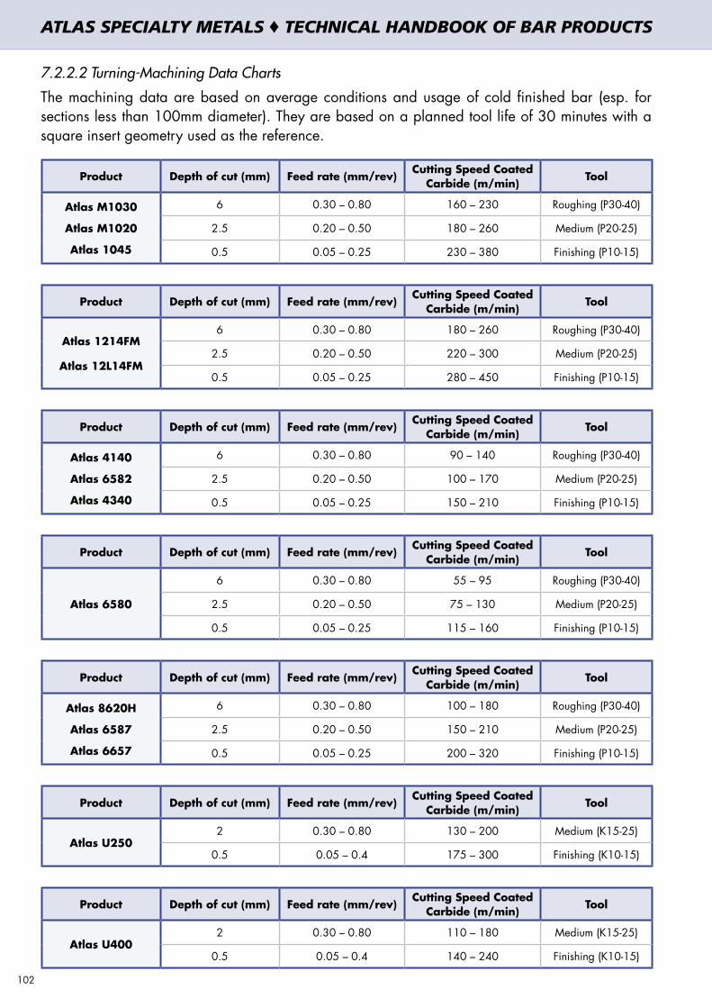
7.2.2.2 Turning-Machining Data Charts
The machining data are based on average conditions and usage of cold finished bar (esp. for sections less than 100mm diameter). They are based on a planned tool life of 30 minutes with a square insert geometry used as the reference.
Product Depth of cut (mm) Feed rate (mm/rev) Cutting Speed Coated Carbide (m/min) Tool
Atlas M1030
Atlas M1020
Atlas 1045
6 0.30 – 0.80 160 – 230 Roughing (P30-40)
2.5 0.20 – 0.50 180 – 260 Medium (P20-25)
0.5 0.05 – 0.25 230 – 380 Finishing (P10-15)
Product Depth of cut (mm) Feed rate (mm/rev) Cutting Speed Coated Carbide (m/min) Tool
Atlas 1214FM
Atlas 12L14FM
6 0.30 – 0.80 180 – 260 Roughing (P30-40)
2.5 0.20 – 0.50 220 – 300 Medium (P20-25)
0.5 0.05 – 0.25 280 – 450 Finishing (P10-15)
Product Depth of cut (mm) Feed rate (mm/rev) Cutting Speed Coated Carbide (m/min) Tool
Atlas 4140
Atlas 6582
Atlas 4340
6 0.30 – 0.80 90 – 140 Roughing (P30-40)
2.5 0.20 – 0.50 100 – 170 Medium (P20-25)
0.5 0.05 – 0.25 150 – 210 Finishing (P10-15)
Product Depth of cut (mm) Feed rate (mm/rev) Cutting Speed Coated Carbide (m/min) Tool
Atlas 6580
6 0.30 – 0.80 55 – 95 Roughing (P30-40)
2.5 0.20 – 0.50 75 – 130 Medium (P20-25)
0.5 0.05 – 0.25 115 – 160 Finishing (P10-15)
Product Depth of cut (mm) Feed rate (mm/rev) Cutting Speed Coated Carbide (m/min) Tool
Atlas 8620H
Atlas 6587
Atlas 6657
6 0.30 – 0.80 100 – 180 Roughing (P30-40)
2.5 0.20 – 0.50 150 – 210 Medium (P20-25)
0.5 0.05 – 0.25 200 – 320 Finishing (P10-15)
Product Depth of cut (mm) Feed rate (mm/rev) Cutting Speed Coated Carbide (m/min) Tool
Atlas U2502 0.30 – 0.80 130 – 200 Medium (K15-25)
0.5 0.05 – 0.4 175 – 300 Finishing (K10-15)
Product Depth of cut (mm) Feed rate (mm/rev) Cutting Speed Coated Carbide (m/min) Tool
Atlas U4002 0.30 – 0.80 110 – 180 Medium (K15-25)
0.5 0.05 – 0.4 140 – 240 Finishing (K10-15)
102
ATLAS SPECIALTY METALS ♦ TECHNICAL HANDBOOK OF BAR PRODUCTS

7.2.3 MILLING
7.2.3.1 General Information:
The following formula are applicable to milling operations.
AAAATTTTLLLLAAAASSSS SSSSPPPPEEEECCCCIIIIAAAALLLLTTTTYYYY MMMMEEEETTTTAAAALLLLSSSS ���� Technical Handbook of Bar Products
Page 103www.atlasmetals.com.au
7777....2222....3333 MMMMIIIILLLLLLLLIIIINNNNGGGG
7.2.3.1 General Information:
The following formula are applicable to milling operations.
Metal removal rate
Cutting speed
Feed speed (or Table travel speed)
Feed per revolution
vf = n · z · fz (mm/min)
n = RPM (rev/min)z = number of teethfz = feed per tooth (mm)
Q = ae · ap · vf (mm3/min)
ae = radial depth of cut (mm)ap = axial depth of cut (mm)vf = table travel (mm/min)
vc =
n = revolutions per minute (rev/min)D = diameter of the cutter (mm)
n · D318
(m/min)
f = z · fz (mm/rev)
z = number of teethfz = feed per tooth (mm)
Cutting speed
Feed speed (or Table travel speed)
Feed per revolution
Metal removal rate
103
ATLAS SPECIALTY METALS ♦ TECHNICAL HANDBOOK OF BAR PRODUCTS

7.2.3.2 Milling - Machining Data Charts
For cutters with indexable carbide inserts.
Product Operation Feed per tooth (mm/rev) Cutting Speed Coated Carbide (m/min) Tool
Atlas M1030
Atlas M1020
Atlas 1045
Roughing 0.15 – 0.5 120 – 180 Roughing (P20-35)
Finishing 0.05 – 0.20 160 – 260 Finishing (P10-15)
Product Operation Feed per tooth (mm/rev) Cutting Speed Coated Carbide (m/min) Tool
Atlas 1214FM
Atlas 12L14FM
Roughing 0.15 – 0.5 140 – 220 Roughing (P20-35)
Finishing 0.05 – 0.20 190 – 310 Finishing (P10-15)
Product Operation Feed per tooth (mm/rev) Cutting Speed Coated Carbide (m/min) Tool
Atlas 4140
Atlas 6582
Atlas 4340
Roughing 0.15 – 0.5 90 – 140 Roughing (P20-35)
Finishing 0.05 – 0.20 110 – 180 Finishing (P10-15)
Product Operation Feed per tooth (mm/rev) Cutting Speed Coated Carbide (m/min) Tool
Atlas 6580Roughing 0.15 – 0.5 60 – 80 Roughing (P20-35)
Finishing 0.05 – 0.20 90 – 150 Finishing (P10-15)
Product Operation Feed per tooth (mm/rev) Cutting Speed Coated Carbide (m/min) Tool
Atlas 8620H
Atlas 6587
Atlas 6657
Roughing 0.15 – 0.5 100 – 170 Roughing (P20-35)
Finishing 0.05 – 0.20 150 – 240 Finishing (P10-15)
Product Operation Feed per tooth (mm/rev) Cutting Speed Coated Carbide (m/min) Tool
Atlas U250Roughing 0.20 – 0.5 130 – 170 Roughing (K15-25)
Finishing 0.05 – 0.20 170 – 250 Finishing (K10-15)
Product Operation Feed per tooth (mm/rev) Cutting Speed Coated Carbide (m/min) Tool
Atlas U400Roughing 0.20 – 0.5 120 – 150 Roughing (K15-25)
Finishing 0.05 – 0.20 140 – 220 Finishing (K10-15)104
ATLAS SPECIALTY METALS ♦ TECHNICAL HANDBOOK OF BAR PRODUCTS

7.2.4 DRILLING
7.2.4.1 General Information
The main formulas for drilling operations are the following:
AAAATTTTLLLLAAAASSSS SSSSPPPPEEEECCCCIIIIAAAALLLLTTTTYYYY MMMMEEEETTTTAAAALLLLSSSS ���� Technical Handbook of Bar Products
Page 105www.atlasmetals.com.au
7777....2222....4444 DDDDRRRRIIIILLLLLLLLIIIINNNNGGGG
7.2.4.1 General Information
The main formulas for drilling operations are the following:
Cutting speed
Feed speed
Metal Removal Rate
Q = 250 · D · f · vc (mm3/min)
D = diameter of the drill (mm)f = feed per rev. (mm/rev)vc = cutting speed (m/min)
vc =
n = revolutions per minute (rev/min)D = diameter of the drill (mm)
n · D318
(m/min)
vf = n · f (mm/min)
n = RPM (rev/min)f = feed per rev. (mm/rev)
Feed speed
Metal Removal Rate
Cutting speed
AAAATTTTLLLLAAAASSSS SSSSPPPPEEEECCCCIIIIAAAALLLLTTTTYYYY MMMMEEEETTTTAAAALLLLSSSS ���� Technical Handbook of Bar Products
Page 105www.atlasmetals.com.au
7777....2222....4444 DDDDRRRRIIIILLLLLLLLIIIINNNNGGGG
7.2.4.1 General Information
The main formulas for drilling operations are the following:
Cutting speed
Feed speed
Metal Removal Rate
Q = 250 · D · f · vc (mm3/min)
D = diameter of the drill (mm)f = feed per rev. (mm/rev)vc = cutting speed (m/min)
vc =
n = revolutions per minute (rev/min)D = diameter of the drill (mm)
n · D318
(m/min)
vf = n · f (mm/min)
n = RPM (rev/min)f = feed per rev. (mm/rev)
105
ATLAS SPECIALTY METALS ♦ TECHNICAL HANDBOOK OF BAR PRODUCTS

7.2.4.2 Drilling – Machining Data Charts
Standard drilling parameters for SOLID CARBIDE drills, for drilling with internal coolant supply and P25-P40/K40 type tool. Feed rates for drill diameter 7-10mm and up represent the middle of a range.
Product Cutting Speed (m/min)
Feed Rate (mm/rev) for various drill diameters (mm)
2-3 4-6 7-10 11-15 16-20 21-32
Atlas M1020
Atlas M1030
Atlas 1045
70 – 90 0.03 – 0.06 0.10 – 0.15 0.20 0.30 0.35 0.40
Atlas 1214FM
Atlas 12L14FM90 – 110 0.03 – 0.06 0.10 – 0.15 0.20 0.30 0.35 0.40
Atlas 4140
Atlas 6582
Atlas 4340
50 – 60 0.03– 0.06 0.05 – 0.11 0.16 0.22 0.25 0.28
Atlas 6580 35 – 45 0.03– 0.06 0.04 – 0.10 0.14 0.20 0.23 0.28
Atlas 8620H
Atlas 6587
Atlas 6657
60 – 80 0.03– 0.06 0.06 – 0.13 0.18 0.25 0.30 0.35
Atlas U250 80 – 100 0.08– 0.12 0.18 – 0.25 0.30 0.35 0.40 0.50
Atlas U400 60 – 80 0.08– 0.12 0.18 – 0.25 0.25 0.30 0.35 0.45
Standard drilling parameters for INDEXABLE CARBIDE INSERT drills, for drilling with external coolant supply and P25-P40/K40 type tool.
Product Cutting Speed (m/min)Feed Rate (mm/rev) for various drill diameters (mm)
< 25 25 – 40 > 40
Atlas M1020
Atlas M1030
Atlas 1045
150 – 270 0.05 – 0.10 0.08 – 0.18 0.10 – 0.20
Atlas 1214FM
Atlas 12L14FM180 – 330 0.05 – 0.10 0.08 – 0.18 0.10 – 0.20
Atlas 4140
Atlas 6582
Atlas 4340
110 – 210 0.05 – 0.10 0.08 – 0.15 0.10 – 0.20
Atlas 6580 110 – 180 0.05 – 0.10 0.08 – 0.15 0.10 – 0.20
Atlas 8620H
Atlas 6587
Atlas 6657
130 – 240 0.05 – 0.12 0.08 – 0.16 0.10 – 0.20
Atlas U250 80 – 180 0.09 – 0.15 0.14 – 0.25 0.18 – 0.30
Atlas U400 80 – 180 0.09 – 0.15 0.14 – 0.24 0.15 – 0.28
106
ATLAS SPECIALTY METALS ♦ TECHNICAL HANDBOOK OF BAR PRODUCTS

Deviation of surface shape from a straight line can be classified into two groups: • Waviness • RoughnessWaviness refers to a low frequency wave-like pattern in the surface as shown in the picture above. Once the wave pattern is filtered out surface roughness is the deviation of the actual surface from a reference line. The so called cut-off length is used to discriminate between waviness and roughness, a common cut-off length for industrial purposes is 0.8mm.
7.2.5 PARTING-OFF
ProductSurface Speed (m/min) for various feed rates (mm/rev)
0.05 – 0.10 0.10 – 0.25
Atlas M1020
Atlas M1030
Atlas 1045
140 – 180 110 – 150
Atlas 1214FM
Atlas 12L14FM160 – 220 130 - 170
Atlas 4140
Atlas 6582
Atlas 4340
90 – 120 80 – 100
Atlas 6580 70 – 90 60 – 80
Atlas 8620H
Atlas 6587
Atlas 6657
120 – 150 100 - 140
Atlas U250 120 – 160 100 – 140
Atlas U400 110 – 150 90 – 130
7.2.6 SURFACE FINISHSurface finish is a characteristic of any machined surface. It is sometimes called surface texture or roughness. What the surface finish of a work piece should be, is based on what the component is supposed to do. The surface finish specification is relevant for the following considerations:Good surface finishes achieve high efficiency. High quality surface finishes coupled with micron fit will produce less friction. For example a 75HP piston engine can loose up to 5HP to the friction of the connecting rods, crank, and piston unless high quality finishes are applied. Good surface finishes increase the wear resistance of two work pieces in an assembly. Good surface finishes reduce the friction between two work pieces in an assembly. Good surface finishes have a cosmetic effect and make parts “look good”. Good surface finish permits the proper function of static and dynamic o-ring seals in
hydraulic and pneumatic equipment.
The following graph shows the meaning of surface roughness as the primary, measurable indicator for surface finish.
••••
107
WAVINESS HEIGHT
ROUGHNESS HEIGHT
ROUGHNESS SPACING
WAVINESS SPACING
CUTOFF LENGTH
ATLAS SPECIALTY METALS ♦ TECHNICAL HANDBOOK OF BAR PRODUCTS

Theoretical surface finish for turning operations:
Ra = surface roughness in µm r = nose radius of the tool in mm f = feed rate in mm/revNote: to convert micrometer into microinch, multiply by 39.4; to convert microinch into micrometer multiply by 0.0254.
The following table gives some reference values Ra for milling and turning operations at various feed rates and nose radiuses.
Theoretical Surface Finish Ra (µm)
Feed rate (mm/rev)
Turning Operation Milling Operation
Nose radius (mm) Nose radius (mm)
0.4 0.8 1.2 1.6 0.4 0.8 1.2 1.6
0.05 0.26 0.13 0.09 0.07 0.39 0.20 0.13 0.10
0.10 1.04 0.52 0.35 0.26 1.57 0.78 0.52 0.39
0.15 2.34 1.17 0.78 0.59 3.55 1.76 1.17 0.88
0.20 4.17 2.08 1.39 1.04 6.35 3.14 2.09 1.56
0.25 3.26 2.17 1.63 4.91 3.26 2.45
0.30 4.69 3.13 2.34 7.09 4.71 3.52
0.40 8.33 5.56 4.17 12.70 8.39 6.27
0.50 8.68 6.51 13.17 9.83
Surface roughness is most commonly measured as ARITHMETIC AVERAGE ROUGHNESS or Ra. Ra is calculated by taking the average of a large number of measured distances from the reference line.
In machining the theoretically achievable surface finish is determined by the nose radius of the tool and the feed rate. In machining practice, many other factors will influence the achieved surface finish, all related to the vibrations that are generated in the workpiece and the tool during the finish machining operation. For carbon and alloy steels (low cold-work hardening), the general rules are the following:
the larger the nose radius, the better the surface finish
the lower the feed rate, the better the surface finish
Generally, feed rate should not be higher than 1/2 of the nose radius and for a very good surface finish 1/4 of the nose radius is recommended. The effect of increasing feed rate is stronger than the effect of increasing nose radius. In other words, the adverse effect on surface finish of doubling the feed rate will not be offset by using a tool with a double nose radius.
The following formulas show how the theoretical surface finish can be calculated.
Theoretical surface finish for milling operations:
AAAATTTTLLLLAAAASSSS SSSSPPPPEEEECCCCIIIIAAAALLLLTTTTYYYY MMMMEEEETTTTAAAALLLLSSSS ���� Technical Handbook of Bar Products
Page 108www.atlasmetals.com.au
7.2.6.1 Theoretical surface finish for milling operations:
2
10002
22 ×
−−
=
frr
Ra
Ra = surface roughness in µm (micrometers or microns)r = nose radius of the tool in mmf = feed rate in mm/rev
7.2.6.2 Theoretical surface finish for turning operations:
( )rf
Ra×
×=
241000
2
Ra = surface roughness in µmr = nose radius of the tool in mmf = feed rate in mm/rev
Note: to convert micrometer into microinch, multiply by 39.4; to convert microinch into micrometer multiplyby 0.0254.
The following table gives some reference values Ra for milling and turning operations at various feed ratesand nose radiuses.
TTTThhhheeeeoooorrrreeeettttiiiiccccaaaallll SSSSuuuurrrrffffaaaacccceeee FFFFiiiinnnniiiisssshhhh RRRRaaaa ((((µµµµmmmm))))
Turning Operation Milling Operation
Nose radius (mm) Nose radius (mm)FFFFeeeeeeeedddd rrrraaaatttteeee((((mmmmmmmm////rrrreeeevvvv))))
0.4 0.8 1.2 1.6 0.4 0.8 1.2 1.6
0.05 0.26 0.13 0.09 0.07 0.39 0.20 0.13 0.10
0.10 1.04 0.52 0.35 0.26 1.57 0.78 0.52 0.39
0.15 2.34 1.17 0.78 0.59 3.55 1.76 1.17 0.88
0.20 4.17 2.08 1.39 1.04 6.35 3.14 2.09 1.56
0.25 3.26 2.17 1.63 4.91 3.26 2.45
0.30 4.69 3.13 2.34 7.09 4.71 3.52
0.40 8.33 5.56 4.17 12.70 8.39 6.27
0.50 8.68 6.51 13.17 9.83
Ra = surface roughness in µm r = nose radius of the tool in mm f = feed rate in mm/rev (micrometers or microns)
••
108
AAAATTTTLLLLAAAASSSS SSSSPPPPEEEECCCCIIIIAAAALLLLTTTTYYYY MMMMEEEETTTTAAAALLLLSSSS ���� Technical Handbook of Bar Products
Page 108www.atlasmetals.com.au
7.2.6.1 Theoretical surface finish for milling operations:
2
10002
22 ×
−−
=
frr
Ra
Ra = surface roughness in µm (micrometers or microns)r = nose radius of the tool in mmf = feed rate in mm/rev
7.2.6.2 Theoretical surface finish for turning operations:
( )rf
Ra×
×=
241000
2
Ra = surface roughness in µmr = nose radius of the tool in mmf = feed rate in mm/rev
Note: to convert micrometer into microinch, multiply by 39.4; to convert microinch into micrometer multiplyby 0.0254.
The following table gives some reference values Ra for milling and turning operations at various feed ratesand nose radiuses.
TTTThhhheeeeoooorrrreeeettttiiiiccccaaaallll SSSSuuuurrrrffffaaaacccceeee FFFFiiiinnnniiiisssshhhh RRRRaaaa ((((µµµµmmmm))))
Turning Operation Milling Operation
Nose radius (mm) Nose radius (mm)FFFFeeeeeeeedddd rrrraaaatttteeee((((mmmmmmmm////rrrreeeevvvv))))
0.4 0.8 1.2 1.6 0.4 0.8 1.2 1.6
0.05 0.26 0.13 0.09 0.07 0.39 0.20 0.13 0.10
0.10 1.04 0.52 0.35 0.26 1.57 0.78 0.52 0.39
0.15 2.34 1.17 0.78 0.59 3.55 1.76 1.17 0.88
0.20 4.17 2.08 1.39 1.04 6.35 3.14 2.09 1.56
0.25 3.26 2.17 1.63 4.91 3.26 2.45
0.30 4.69 3.13 2.34 7.09 4.71 3.52
0.40 8.33 5.56 4.17 12.70 8.39 6.27
0.50 8.68 6.51 13.17 9.83
(24 x r)
ATLAS SPECIALTY METALS ♦ TECHNICAL HANDBOOK OF BAR PRODUCTS
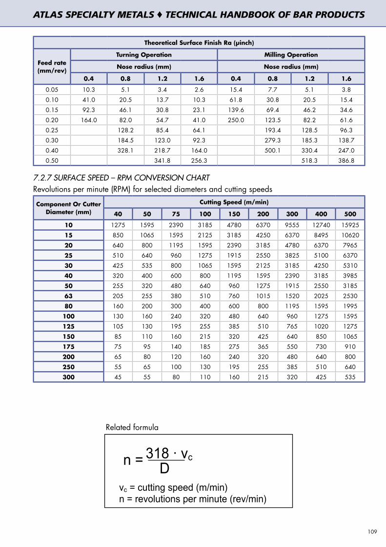
Theoretical Surface Finish Ra (µinch)
Feed rate (mm/rev)
Turning Operation Milling Operation
Nose radius (mm) Nose radius (mm)
0.4 0.8 1.2 1.6 0.4 0.8 1.2 1.6
0.05 10.3 5.1 3.4 2.6 15.4 7.7 5.1 3.8
0.10 41.0 20.5 13.7 10.3 61.8 30.8 20.5 15.4
0.15 92.3 46.1 30.8 23.1 139.6 69.4 46.2 34.6
0.20 164.0 82.0 54.7 41.0 250.0 123.5 82.2 61.6
0.25 128.2 85.4 64.1 193.4 128.5 96.3
0.30 184.5 123.0 92.3 279.3 185.3 138.7
0.40 328.1 218.7 164.0 500.1 330.4 247.0
0.50 341.8 256.3 518.3 386.8
7.2.7 SURFACE SPEED – RPM CONVERSION CHARTRevolutions per minute (RPM) for selected diameters and cutting speeds
Component Or Cutter Diameter (mm)
Cutting Speed (m/min)
40 50 75 100 150 200 300 400 500
10 1275 1595 2390 3185 4780 6370 9555 12740 15925
15 850 1065 1595 2125 3185 4250 6370 8495 10620
20 640 800 1195 1595 2390 3185 4780 6370 7965
25 510 640 960 1275 1915 2550 3825 5100 6370
30 425 535 800 1065 1595 2125 3185 4250 5310
40 320 400 600 800 1195 1595 2390 3185 3985
50 255 320 480 640 960 1275 1915 2550 3185
63 205 255 380 510 760 1015 1520 2025 2530
80 160 200 300 400 600 800 1195 1595 1995
100 130 160 240 320 480 640 960 1275 1595
125 105 130 195 255 385 510 765 1020 1275
150 85 110 160 215 320 425 640 850 1065
175 75 95 140 185 275 365 550 730 910
200 65 80 120 160 240 320 480 640 800
250 55 65 100 130 195 255 385 510 640
300 45 55 80 110 160 215 320 425 535
Related formula
AAAATTTTLLLLAAAASSSS SSSSPPPPEEEECCCCIIIIAAAALLLLTTTTYYYY MMMMEEEETTTTAAAALLLLSSSS ���� Technical Handbook of Bar Products
Page 109www.atlasmetals.com.au
TTTThhhheeeeoooorrrreeeettttiiiiccccaaaallll SSSSuuuurrrrffffaaaacccceeee FFFFiiiinnnniiiisssshhhh RRRRaaaa ((((µµµµiiiinnnncccchhhh))))
Turning Operation Milling Operation
Nose radius (mm) Nose radius (mm)FFFFeeeeeeeedddd rrrraaaatttteeee((((mmmmmmmm////rrrreeeevvvv))))
0.4 0.8 1.2 1.6 0.4 0.8 1.2 1.6
0.05 10.3 5.1 3.4 2.6 15.4 7.7 5.1 3.8
0.10 41.0 20.5 13.7 10.3 61.8 30.8 20.5 15.4
0.15 92.3 46.1 30.8 23.1 139.6 69.4 46.2 34.6
0.20 164.0 82.0 54.7 41.0 250.0 123.5 82.2 61.6
0.25 128.2 85.4 64.1 193.4 128.5 96.3
0.30 184.5 123.0 92.3 279.3 185.3 138.7
0.40 328.1 218.7 164.0 500.1 330.4 247.0
0.50 341.8 256.3 518.3 386.8
7777....2222....7777 SSSSUUUURRRRFFFFAAAACCCCEEEE SSSSPPPPEEEEEEEEDDDD –––– RRRRPPPPMMMM CCCCOOOONNNNVVVVEEEERRRRSSSSIIIIOOOONNNN CCCCHHHHAAAARRRRTTTT
Revolutions per minute (RPM) for selected diameters and cutting speeds
CCCCuuuuttttttttiiiinnnngggg SSSSppppeeeeeeeedddd ((((mmmm////mmmmiiiinnnn))))CCCCoooommmmppppoooonnnneeeennnntttt
OOOOrrrr CCCCuuuutttttttteeeerrrr DDDDiiiiaaaammmmeeeetttteeeerrrr((((mmmmmmmm)))) 44440000 55550000 77775555 111100000000 111155550000 222200000000 333300000000 444400000000 555500000000
11110000 1275 1595 2390 3185 4780 6370 9555 12740 15925
11115555 850 1065 1595 2125 3185 4250 6370 8495 10620
22220000 640 800 1195 1595 2390 3185 4780 6370 7965
22225555 510 640 960 1275 1915 2550 3825 5100 6370
33330000 425 535 800 1065 1595 2125 3185 4250 5310
44440000 320 400 600 800 1195 1595 2390 3185 3985
55550000 255 320 480 640 960 1275 1915 2550 3185
66663333 205 255 380 510 760 1015 1520 2025 2530
88880000 160 200 300 400 600 800 1195 1595 1995
111100000000 130 160 240 320 480 640 960 1275 1595
111122225555 105 130 195 255 385 510 765 1020 1275
111155550000 85 110 160 215 320 425 640 850 1065
111177775555 75 95 140 185 275 365 550 730 910
222200000000 65 80 120 160 240 320 480 640 800
222255550000 55 65 100 130 195 255 385 510 640
333300000000 45 55 80 110 160 215 320 425 535
Related formula
n =
vc = cutting speed (m/min)n = revolutions per minute (rev/min)
318 · vc
D
109
ATLAS SPECIALTY METALS ♦ TECHNICAL HANDBOOK OF BAR PRODUCTS

7.3 MACHINING OF STAINLESS STEEL
7.3.1 UGIMA® 303UGIMA® 303 = UGIMA®NSU = UGIMA®4305
C = 0.10 % max Cr = 17.0 – 19.0 % Ni = 8.0 – 10.0 % Mn = 2 % max S = 0.25 – 0.35 %
Conforms to standards: ASTM A276 Grade 303 – EN 10088–3 : 1.4305 X8CrNiS18–9 – AISI 303 7.3.1.1 Cutting parameters for classical machines, multi–spindle, single–spindle screw machine:* Second choice possible HSS Tools Carbide tool
Machining operation
Depth of cut or width (mm)
Cutting speed (m/min)
Feed (mm/rev)
Type of tool
Cutting speed (m/min)
Feed (mm/rev)
Type of tool
Ø Bar ≤
25.4mm
TURNING
Ø Bar > 25.4mm
123
45.5 – 55.539.5 – 45.533.5 – 42.5
0.13–0.20.15–0.250.17–0.30 S4–S5
(S9)
145 – 215120 – 155120 – 145
0.13–0.20.15–0.250.17–0.30
P10-M10P20-M20P25-M20
123
48.5 – 57.542.5 – 51.536.5 – 45.5
0.13–0.20.15–0.250.17–0.30
160 – 275140 – 250130 – 225
0.13–0.20.15–0.250.17–0.30
P10-M10P20-M20P25-M20
Ø Bar ≤
25.4mm
FORMING–
GROOVING
Ø Bar > 25.4mm
26
12.72551
42.5 – 54.539.5 – 51.539.5 – 48.539.5 – 48.539.5 – 48.5
0.08 – 0.100.08 – 0.100.07 – 0.090.07 – 0.090.065–0.085 S4–S5
(S9)
130 – 140105 – 130105 – 130105 – 130105 – 120
0.08 – 0.100.08 – 0.100.07 – 0.090.07 – 0.09
0.065–0.085
P20-M20P20-M20P25-M20P25-M20P25-M20
26
12.72551
45.5 – 57.542.5 – 54.542.5 – 51.542.5 – 51.542.5 – 51.5
0.09 – 0.110.09 – 0.110.08 – 0.100.08 – 0.100.07 – 0.09
135 –170120 – 140120 – 130115 – 130115 – 130
0.09 – 0.110.09 – 0.110.08 – 0.100.08 – 0.100.07 – 0.09
P20-M20P20-M20P25-M20P25-M20P25-M20
Ø Bar ≤
25.4mm
SHAVING–
SKIVING
Ø Bar > 25.4mm
26
12.72551
42.5 – 54.539.5 – 51.539.5 – 48.539.5 – 48.539.5 – 48.5
0.03 – 0.0450.04 – 0.060.045–0.0650.045–0.0650.04 – 0.06 S4–S5
(S9)
130 – 140105 – 130105 – 130105 – 130105 – 120
0.03 – 0.0450.04 – 0.06
0.045–0.0650.045–0.0650.04 – 0.06
P20-M20P20-M20P25-M20P25-M20P25-M20
26
12.72551
45.5 – 57.542.5 – 54.542.5 – 51.542.5 – 51.542.5 – 51.5
0.03 – 0.0450.04 – 0.060.045–0.0650.045–0.0650.04 – 0.06
135 –170120 – 140120 – 130115 – 130115 – 130
0.03 – 0.0450.04 – 0.06
0.045–0.0650.045–0.0650.04 – 0.06
P20-M20P20-M20P25-M20P25-M20P25-M20
Ø Bar ≤
25.4mm
CUT–OFF or
PART–OFF
123
39.5 – 45.639.5 – 45.636.5 – 42.5
0.04 – 0.060.045–0.0650.065–0.085 S4–S9
(S11)
100 – 12095 – 12090 – 110
0.045–0.0650.065–0.0850.09 – 0.11
P25-M20P25-M20P25-M20
2 36
42.5 – 48.544 – 45.5
36.5 – 42.5
0.045–0.0650.065–0.0850.09 – 0.11
110 – 130100 – 13090 – 110
0.065–0.0850.09–0.110.10–0.15
P25-M20P25-M20P25-M20
DRILLING
136121520
25–35
0.025 – 0.050.12 – 0.200.19 – 0.270.25 – 0.320.28 – 0.350.32 – 0.40
S4 100–220
0.025 – 0.050.05 – 0.150.07 – 0.20.10 – 0.250.13 – 0.270.15 – 0.30
P20-P40 or K40
TiN coated
REMARKS ON TOOLING:The use of coated tools (tips or insert) increases the tool life by 20% to 50% using the same cutting parameters, or it increases the cutting conditions (speed) by 10% to 15% using the same tool wear. We recommended a TiN coating (PVD or CVD).
110
ATLAS SPECIALTY METALS ♦ TECHNICAL HANDBOOK OF BAR PRODUCTS

7.3.1.2 Cutting conditions for CNC machinery:
Brazed Carbide
Uncoated Carbide Insert
Coated Carbide Insert
Machining Operation
Depth of cut or Width (mm)
Cutting Speed (m/min)
Cutting Speed (m/min)
Cutting Speed (m/min)
Feed (mm/rev)
Type of Tool
Ø Bar ≤ 25.4mm
TURNING
Ø Bar > 25.4mm
1
2
3
130 - 200
120 - 155
100 - 135
165 - 245
165 - 230
130 - 195
180 - 450
165 - 400
165 - 355
0.15 - 0.2
0.2 - 0.3
0.3 - 0.4
P10-M10
P20-M20
P25-M251
3
6
150 - 275
120 - 180
100 - 150
210 - 395
150 - 320
140 - 260
300 - 550
220 - 450
180 - 335
0.15 - 0.2
0.3 - 0.4
0.4 - 0.5
P10-M10
P20-M20
P25-M25
Ø Bar ≤ 25.4mm
GROOVING
Ø Bar > 25.4mm
1
3
6
110 - 140
100 - 130
90 - 120
130 - 170
120 - 150
110 - 140
140 - 200
130 - 180
130 -160
0.05 - 0.07
0.07 - 0.10
0.08 - 0.10
P20-M20
P20-M20
P25-M252
3
6
120 - 170
110 - 150
100 - 140
120 - 180
120 - 180
110 - 160
150 - 220
140 - 210
130 - 170
0.06 - 0.08
0.08 -0.10
0.09 - 0.11
P20-M20
P20-M20
P25-M25
Ø Bar ≤ 25.4mm
CUT-OFF or
PART OFF
Ø Bar > 25.4mm
1
2
3
95 - 115
80 - 100
75 - 85
105 - 145
95 - 130
85 - 110
135 - 185
120 - 170
105 - 145
0.05 - 0.07
0.06 - 0.08
0.07 - 0.09
P25-M25
P25-M25
P25-M252
3
6
105 - 125
95 - 115
85 - 95
120 - 160
105 - 140
90 - 120
150 - 200
135 - 190
120 - 160
0.07 - 0.09
0.08 - 0.10
0.09 - 0.15
P25-M25
P25-M25
P25-M25
HSS Drill type N Plain Carbide Drill
Machining Operation
Diameter (mm)
Cutting speed (m/min)
Feed (mm/rev)
Type of tool
Cutting Speed (m/min)
Feed (mm/rev)
Type of tool
DRILLING
1
3
6
12
15
20
25-35
0.025 - 0.05
0.12 - 0.20
0.19 - 0.27
0.25 - 0.32
0.28 - 0.35
0.32 - 0.40
S4 100-220
0.025 - 0.05
0.05 - 0.15
0.07 - 0.2
0.10 – 0.25
0.13 – 0.27
0.15 – 0.30
P20-P40 or
K40TiN coated
DRILLING: 1. The quality of the cutting lubricant is important. There must be a large quantity (pressure+steady flow) coming
through regularly. On the large drills, it is recommended to use drills with oil holes (internal lubrication).2. The cutting conditions recommended are valid for a depth of drilling equal to 4 x f maximum.3. We would advise you use drills with a pointed angle of approximately 118°.
LUBRICANT: We recommend lubricant with extreme pressure additives.
REMARKS ON THE TOOLING: For the type of coating of the coated carbide tips (inserts), we recommend those with a final visible layer of TiN, generally gold colour.
111
ATLAS SPECIALTY METALS ♦ TECHNICAL HANDBOOK OF BAR PRODUCTS

7.3.2 UGIMA® 303XL
C = 0.07 % max Cr = 17.0 - 18.0 % Ni = 8.2 – 9.5 % Mn = 1.5 – 2.0 % S = 0.35 – 0.40%
Conforms to standards: ASTM A276 Grade 303 - AISI 303
7.3.2.1 Cutting parameters for classical machines, multi-spindle, single-spindle screw machine:
* Second choice possible HSS Tools Carbide Tool
Machining Operation
Depth of cut or width (mm)
Cutting speed (m/min)
Feed (mm/rev)
Type of tool
Cutting speed (m/min)
Feed (mm/rev)
Type of tool
Ø Bar ≤ 25.4mm
TURNING
Ø Bar > 25.4mm
123
40 – 60 35 – 5028 – 48
0.13 – 0.300.15 – 0.350.17 – 0.40 S4–S5
(S9)
140 – 160115 – 220100 – 190
0.13 – 0.300.15 – 0.370.17 – 0.45
P10-M10P20-M20P25-M20
123
48– 6237– 5734 – 52
0.13 – 0.300.15 – 0.350.17 – 0.40
150 – 340120 – 290100 – 260
0.13 – 0.300.15 – 0.370.17 – 0.45
P10-M10P20-M20 P25-M20
Ø Bar ≤ 25.4mm
FORMING
–GROOVING
Ø Bar > 25.4mm
26
12.72551
38 – 6036 – 5634 – 5428 – 5226 – 52
0.07 – 0.120.07 – 0.120.06 – 0.110.05 – 0.100.04 – 0.09 S4–S5
(S9)
100 – 170100 – 16090 – 15580 – 15070 – 145
0.07 – 0.120.07 – 0.120.06 – 0.110.05 – 0.09
0.04 – 0.085
P20-M20P20-M20P25-M20P25-M20P25-M20
26
12.72551
41 – 6339 – 5937 – 5731 – 5529 – 55
0.07 – 0.120.07 – 0.120.06 – 0.110.05 – 0.100.04 – 0.09
110 – 195100 – 17595 – 16590 – 15575 – 150
0.07 – 0.120.07 – 0.120.06 – 0.110.05 – 0.09
0.04 – 0.085
P20-M20P20-M20P25-M20P25-M20P25-M20
Ø Bar ≤ 25.4mm
SHAVING–
SKIVING
Ø Bar > 25.4mm
26
12.72551
38 – 6036 – 5634 – 5428 – 5226 – 52
0.04 – 0.0700.04 – 0.0750.045 – 0.0750.045 – 0.0750.04 – 0.08 S4–S5
(S9)
100 – 170100 – 16090 – 15580 – 15070 – 145
0.04 – 0.0700.04 – 0.0750.045 – 0.0750.045 – 0.075
0.04 – 0.08
P20-M20P20-M20P25-M20P25-M20P25-M20
26
12.72551
41 – 6339 – 5937 – 5731 – 5529 – 55
0.04 – 0.0700.04 – 0.0750.045 – 0.0750.045 – 0.0750.04 – 0.08
110 – 195100 – 17595 – 16590 – 15575 – 150
0.04 – 0.0700.04 – 0.0750.045 – 0.0750.045 – 0.075
0.04 – 0.08
P20-M20P20-M20P25-M20P25-M20P25-M20
Ø Bar ≤ 25.4mm
CUT–OFF or
PART–OFF
Ø Bar > 25.4mm
123
37 – 5235 – 5034 – 48
0.03 – 0.0650.04 – 0.080.05 – 0.09 S4–S9
(S11)
90 – 16075 – 15060 – 145
0.03 – 0.070.04 – 0.090.05 – 0.12
P25-M20P25-M20P25-M20
2 36
40 – 5538 – 5336 – 51
0.04– 0.070.05– 0.0850.06 – 0.11
90 – 17075 – 16060 – 150
0.04 – 0.090.05 – 0.120.10 – 0.15
P25-M20P25-M20P25-M20
DRILLING
136121520
15-45
0.025 – 0.060.08 – 0.270.15 – 0.320.20 – 0.370.25 – 0.420.30 – 0.47
S4 50 – 250
0.025 – 0.0550.05 – 0.220.07 – 0.270.10 – 0.320.13 – 0.370.15 – 0.40
P20–P40 or K40
TiN coated
REMARKS ON TOOLING: The use of coated tools (tips or insert) increases the tool life by 20% to 50% using the same cutting parameters, or it increases the cutting conditions (speed) by 10% to 15% using the same tool wear. We recommended a TiN coating (PVD or CVD).
112
ATLAS SPECIALTY METALS ♦ TECHNICAL HANDBOOK OF BAR PRODUCTS

7.3.2.2 Cutting conditions for CNC machinery:
Brazed Carbide
Uncoated Carbide Insert
Coated Carbide Insert
Machining Operation
Depth of cut or Width (mm)
Cutting Speed (m/min)
Cutting Speed (m/min)
Cutting Speed (m/min)
Feed (mm/rev)
Type of Tool
Ø Bar ≤ 25.4mm
TURNING
Ø Bar > 25.4mm
1
2
3
110 – 240
100 – 200
80 – 170
165 – 245
165 – 230
130 – 195
180 – 490
165 – 440
155 – 390
0.13 – 0.27
0.15 – 0.37
0.17 – 0.47
P10 – M10
P20 – M20
P25 – M251
3
6
130 – 320
100 – 230
80 – 185
180 – 440
130 – 365
120 – 295
260 – 590
210 – 485
160 – 370
0.13 – 0.27
0.25 – 0.47
0.27 – 0.57
P10 – M10
P20 – M20
P25 – M25
Ø Bar ≤ 25.4mm
GROOVING
Ø Bar > 25.4mm
1
3
6
90 – 170
75 – 160
60 – 150
110 – 200
95 – 180
80 –170
120 – 230
105 – 210
100 – 190
0.04 – 0.12
0.06 – 0.11
0.07 – 0.10
P20 – M20
P20 – M20
P25 – M252
3
6
100 – 200
85 – 180
70 – 175
100 – 210
120 – 200
110 – 190
130 – 255
115 – 240
110 – 200
0.07 – 0.12
0.07 – 0.11
0.07 – 0.11
P20 – M20
P20 – M20
P25 – M25
Ø Bar ≤ 25.4mm
CUT-OFF or
PART OFF
Ø Bar > 25.4mm
1
2
3
75 – 145
60 – 130
55 – 155
105 – 145
95 – 130
85 – 110
115 – 215
100 – 200
85 – 175
0.04 – 0.07
0.05 – 0.085
0.06 – 0.11
P25 – M25
P25 – M25
P25 – M252
3
6
85 – 155
75 – 145
65 – 125
100 – 190
85 – 170
70 – 150
130 – 230
115 – 220
100 – 190
0.04 – 0.07
0.05 – 0.085
0.06 – 0.11
P25 – M25
P25 – M25
P25 – M25
HSS Drill type N Plain Carbide Drill
Machining Operation
Diameter (mm)
Cutting speed (m/min)
Feed (mm/rev)
Type of tool
Cutting Speed (m/min)
Feed (mm/rev)
Type of tool
DRILLING
136121520
15 – 45
0.025 – 0.060.08 – 0.270.15 – 0.320.20 – 0.370.25 – 0.420.30 – 0.47
S4 50 – 250
0.025 – 0.0550.05 – 0.220.07 – 0.270.10 – 0.320.13 – 0.370.15 – 0.40
P20-P40
or K40TiN coated
DRILLING: 1. The quality of the cutting lubricant is important. There must be a large quantity (pressure+steady flow) coming
through regularly. On the large drills, it is recommended to use drills with oil holes (internal lubrication).2. The cutting conditions recommended are valid for a depth of drilling equal to 4 x f maximum.3. We would advise you use drills with a pointed angle of approximately 118°.
LUBRICANT: We recommend lubricant with extreme pressure additives.
REMARKS ON THE TOOLING: For the type of coating of the coated carbide tips (inserts), we recommend those with a final visible layer of TiN, generally gold colour.
113
ATLAS SPECIALTY METALS ♦ TECHNICAL HANDBOOK OF BAR PRODUCTS

7.3.3 UGIMA® 304/304L
C = 0.03 % max Cr = 18.0 – 20.0 % Ni = 8 – 12 %
Conforms to standards: ASTM A276 Grade 304/304L, EN 10088-3 grade 1.4301/1.4307 X5CrNi18-10/X2CrNi18-9, AISI 304/304L
7.3.3.1 Cutting parameters for classical machines, multi-spindle, single-spindle screw machine:
* Second choice possible HSS Tools Carbide Tool
Machining Operation
Depth of cut or width (mm)
Cutting speed (m/min)
Feed (mm/rev)
Type of tool
Cutting speed (m/min)
Feed (mm/rev)
Type of tool
Ø Bar ≤ 25.4mm
TURNING
Ø Bar > 25.4mm
123
30 – 3827 – 3525 – 31
0.13 – 0.20.15 – 0.250.17 – 0.30 S4–S5
(S9)*
100 – 15590 – 13080 – 115
0.13 – 0.20.15 – 0.250.17 – 0.30
P10 - M10P20 - M20P25 - M20
123
32 – 4029 – 3827 – 33
0.13 – 0.20.15 – 0.250.17 – 0.30
110 – 190100 – 16090 – 135
0.13 – 0.20.15 – 0.250.17 – 0.30
P10 - M10P20 - M20P25 - M20
Ø Bar ≤ 25.4mm
FORMING
–GROOVING
Ø Bar > 25.4mm
26
12.72551
31 – 3831 – 3729 – 3629 – 3629 – 36
0.07 – 0.080.075 – 0.085
0.07 – 0.080.06 – 0.070.05 – 0.06 S4–S5
(S9)
80 – 10075 – 9075 – 9070 – 8565 – 80
0.07 – 0.080.075 – 0.0850.07 – 0.080.06 – 0.070.05 – 0.06
P20 - M20P20 - M20P25 - M20P25 - M20P25 - M20
26
12.72551
35 – 4133 – 3832 – 3831 – 3831 – 38
0.075 – 0.0850.08 – 0.09
0.075 – 0.0850.065 – 0.0750.055 – 0.065
90 –11085 – 10080 – 9580 – 9075 – 85
0.075 – 0.0850.08 – 0.09
0.075 – 0.0850.065 – 0.0750.055 – 0.065
P20 - M20P20 - M20P25 - M20P25 - M20P25 - M20
Ø Bar ≤ 25.4mm
SHAVING–
SKIVING
Ø Bar > 25.4mm
26
12.72551
31 – 3831 – 3729 – 3629 – 3629 – 36
0.045 – 0.0550.05 – 0.06
0.055 – 0.0650.06 – 0.070.07 – 0.08 S4–S5
(S9)*
80 – 10075 – 9075 – 9070 – 8565 – 80
0.045 – 0.0550.05 – 0.06
0.055 – 0.0650.06 – 0.070.07 – 0.08
P20 - M20P20 - M20P25 - M20P25 - M20P25 - M20
26
12.72551
35 – 4133 – 3832 – 3831 – 3831 – 38
0.045 – 0.0550.05 – 0.06
0.055 – 0.0650.06 – 0.070.07 – 0.08
90 –11085 – 10080 – 9580 – 9075 – 85
0.045 – 0.0550.05 – 0.06
0.055 – 0.0650.06 – 0.070.07 – 0.08
P20 - M20P20 - M20P25 - M20P25 - M20P25 - M20
Ø Bar ≤ 25.4mm
CUT–OFF or
PART–OFF
Ø Bar > 25.4mm
123
31 – 3529 – 3422 – 26
0.05 – 0.060.07 – 0.0750.075 – 0.08 S11
(S9)*
75 – 9570 – 8560 – 75
0.05 – 0.060.07 – 0.0750.075 – 0.08
P25 - M20P25 - M20P25 - M20
2 36
32 – 3829 – 3324 – 29
0.07 – 0.0750.075 – 0.085
0.08 – 0.09
80 – 10070 – 9065 – 80
0.07 – 0.0750.075 – 0.0850.08 – 0.09
P25 - M20P25 - M20P25 - M20
DRILLING
136121520
17 – 25
0.02 – 0.040.06 – 0.100.09 – 0.14
0.13 – 0.220.16 – 0.260.20 – 0.30
S4 30 – 65
0.02 – 0.040.05 – 0.090.07 – 0.120.10 – 0.160.13 – 0.200.16 – 0.23
P20–P40 or K40
TiN coated
REMARKS ON TOOLING:The use of coated tools (tips or insert) increases the tool life by 20% to 50% using the same cutting parameters, or it increases the cutting conditions (speed) by 10% to 15% using the same tool wear. We recommended a TiN coating (PVD or CVD).
114
ATLAS SPECIALTY METALS ♦ TECHNICAL HANDBOOK OF BAR PRODUCTS
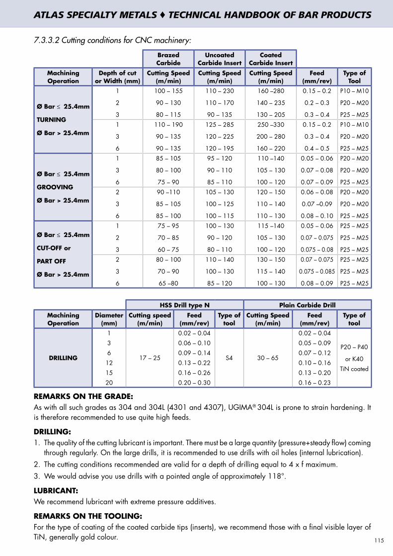
7.3.3.2 Cutting conditions for CNC machinery:
Brazed Carbide
Uncoated Carbide Insert
Coated Carbide Insert
Machining Operation
Depth of cut or Width (mm)
Cutting Speed (m/min)
Cutting Speed (m/min)
Cutting Speed (m/min)
Feed (mm/rev)
Type of Tool
Ø Bar ≤ 25.4mm
TURNING
Ø Bar > 25.4mm
1
2
3
100 – 155
90 – 130
80 – 115
110 – 230
110 – 170
90 – 135
160 –280
140 – 235
130 – 205
0.15 – 0.2
0.2 – 0.3
0.3 – 0.4
P10 – M10
P20 – M20
P25 – M251
3
6
110 – 190
90 – 135
90 – 135
125 – 285
120 – 225
120 – 195
250 –330
200 – 280
160 – 220
0.15 – 0.2
0.3 – 0.4
0.4 – 0.5
P10 – M10
P20 – M20
P25 – M25
Ø Bar ≤ 25.4mm
GROOVING
Ø Bar > 25.4mm
1
3
6
85 – 105
80 – 100
75 – 90
95 – 120
90 – 110
85 – 110
110 –140
105 – 130
100 – 120
0.05 – 0.06
0.07 – 0.08
0.07 – 0.09
P20 – M20
P20 – M20
P25 – M252
3
6
90 –110
85 – 105
85 – 100
105 – 130
100 – 125
100 – 115
120 – 150
110 – 140
110 – 130
0.06 – 0.08
0.07 –0.09
0.08 – 0.10
P20 – M20
P20 – M20
P25 – M25
Ø Bar ≤ 25.4mm
CUT-OFF or
PART OFF
Ø Bar > 25.4mm
1
2
3
75 – 95
70 – 85
60 – 75
100 – 130
90 – 120
80 – 110
115 –140
105 – 130
100 – 120
0.05 – 0.06
0.07 – 0.075
0.075 – 0.08
P25 – M25
P25 – M25
P25 – M252
3
6
80 – 100
70 – 90
65 –80
110 – 140
100 – 130
85 – 120
130 – 150
115 – 140
100 – 130
0.07 – 0.075
0.075 – 0.085
0.08 – 0.09
P25 – M25
P25 – M25
P25 – M25
HSS Drill type N Plain Carbide Drill
Machining Operation
Diameter (mm)
Cutting speed (m/min)
Feed (mm/rev)
Type of tool
Cutting Speed (m/min)
Feed (mm/rev)
Type of tool
DRILLING
136121520
17 – 25
0.02 – 0.040.06 – 0.100.09 – 0.140.13 – 0.220.16 – 0.260.20 – 0.30
S4 30 – 65
0.02 – 0.040.05 – 0.090.07 – 0.120.10 – 0.160.13 – 0.200.16 – 0.23
P20 – P40
or K40TiN coated
REMARKS ON THE GRADE: As with all such grades as 304 and 304L (4301 and 4307), UGIMA® 304L is prone to strain hardening. It is therefore recommended to use quite high feeds.
DRILLING: 1. The quality of the cutting lubricant is important. There must be a large quantity (pressure+steady flow) coming
through regularly. On the large drills, it is recommended to use drills with oil holes (internal lubrication).2. The cutting conditions recommended are valid for a depth of drilling equal to 4 x f maximum.3. We would advise you use drills with a pointed angle of approximately 118°.
LUBRICANT: We recommend lubricant with extreme pressure additives.
REMARKS ON THE TOOLING: For the type of coating of the coated carbide tips (inserts), we recommend those with a final visible layer of TiN, generally gold colour. 115
ATLAS SPECIALTY METALS ♦ TECHNICAL HANDBOOK OF BAR PRODUCTS

7.3.4 ATLAS UGIMA® 316/316L
C = 0.03 % max Cr = 16.5 – 18.5 % Ni = 10 – 13 % Mo = 2.0 – 2.5 %
Conforms to standards: ASTM A276 Grade 316/316L, EN 10088-3 grade 1.4401/1.4404, X5CrNiMo17-12-2/X2CrNiMo17-12-2, AISI grade 316/316L
7.3.4.1 Cutting parameters for classical machines, multi-spindle, single-spindle screw machine:
* Second choice possible HSS Tools Carbide Tool
Machining Operation
Depth of cut or width (mm)
Cutting speed (m/min)
Feed (mm/rev)
Type of tool
Cutting speed (m/min)
Feed (mm/rev)
Type of tool
Ø Bar ≤ 25.4mm
TURNING
Ø Bar > 25.4mm
123
28 – 3625 – 3324 – 29
0.13 – 0.20.15 – 0.250.17 – 0.30 S4–S5
(S9)*
90 – 14080 – 12575 – 105
0.13 – 0.20.15 – 0.250.17 – 0.30
P10 - M10P20 - M20P25 - M20
123
30 – 38 27 – 3626 – 31
0.13 – 0.20.15 – 0.250.17 – 0.30
100 – 17090 – 12080 – 110
0.13 – 0.20.15 – 0.250.17 – 0.30
P10 - M10P20 - M20P25 - M20
Ø Bar ≤ 25.4mm
FORMING
–GROOVING
Ø Bar > 25.4mm
26
12.72551
31 – 3630 – 3529 – 3429 – 3429 – 34
0.07 – 0.080.07 – 0.08
0.065 – 0.0750.055 – 0.0650.045 – 0.055 S4–S5
(S9)
75 – 9070 – 8570 – 8565 – 8060 – 70
0.07 – 0.080.07 – 0.08
0.065 – 0.0750.055 – 0.0650.045 – 0.055
P20 - M20P20 - M20P25 - M20P25 - M20P25 - M20
26
12.72551
33 – 3832 – 3631 – 3531 – 3531 – 35
0.075 – 0.0850.075 – 0.085
0.07 – 0.080.06 – 0.070.05 – 0.06
80 – 9575 – 9075 – 9070 – 8565 – 75
0.075 – 0.0850.075 – 0.0850.07 – 0.080.06 – 0.070.05 – 0.06
P20 - M20P20 - M20P25 - M20P25 - M20P25 - M20
Ø Bar ≤ 25.4mm
SHAVING–
SKIVING
Ø Bar > 25.4mm
26
12.72551
31 – 3630 – 3529 – 3429 – 3429 – 34
0.040.05
0.0550.0550.075 S4–S5
(S9)*
75 – 9070 – 8570 – 8565 – 8060 – 70
0.040.050.0550.0550.075
P20 - M20P20 - M20P25 - M20P25 - M20P25 - M20
26
12.72551
33 – 3832 – 3631 – 3531 – 3531 – 35
0.040.05
0.0550.0550.075
80 – 9575 – 9075 – 9070 – 8565 – 75
0.040.050.0550.0550.075
P20 - M20P20 - M20P25 - M20P25 - M20P25 - M20
Ø Bar ≤ 25.4mm
CUT–OFF or
PART–OFF
Ø Bar > 25.4mm
123
29 – 3226 – 3020 – 24
0.05 – 0.060.07 – 0.0750.075 – 0.08 S11
(S9)*
65 – 8560 – 7555 – 65
0.05 – 0.060.07 – 0.0750.075 – 0.08
P25 - M20P25 - M20P25 - M20
2 36
30 – 3626 – 3022 – 26
0.055 – 0.0650.075 – 0.085
0.08 – 0.09
70 – 9065 – 8060 – 70
0.055 – 0.0650.075 – 0.0850.08 – 0.09
P25 - M20P25 - M20P25 - M20
DRILLING
136121520
15 – 22
0.02 – 0.040.06 – 0.100.09 – 0.140.13 – 0.220.16 – 0.260.20 - 0.30
S4 30 – 60
0.02 – 0.040.05 – 0.090.07 – 0.120.10 – 0.160.13 – 0.200.16 – 0.23
P20 – P40 or K40
TiN coated
REMARKS ON TOOLING: The use of coated tools (tips or insert) increases the tool life by 20% to 50% using the same cutting parameters, or it increases the cutting conditions (speed) by 10% to 15% using the same tool wear. We recommended a TiN coating (PVD or CVD).
116
ATLAS SPECIALTY METALS ♦ TECHNICAL HANDBOOK OF BAR PRODUCTS

7.3.4.2 Cutting conditions for CNC machinery:
Brazed Carbide
Uncoated Carbide Insert
Coated Carbide Insert
Machining Operation
Depth of cut or Width (mm)
Cutting Speed (m/min)
Cutting Speed (m/min)
Cutting Speed (m/min)
Feed (mm/rev)
Type of Tool
Ø Bar ≤ 25.4mm
TURNING
Ø Bar > 25.4mm
1
2
3
90 – 150
80 – 125
75 – 105
105 – 220
100 – 160
90 – 150
140 – 260
130 – 210
120 – 180
0.15 – 0.2
0.2 – 0.3
0.3 – 0.4
P10 – M10
P20 – M20
P25 – M251
3
6
100 – 170
80 – 110
75 – 110
115 –230
105 – 170
105 – 150
230 – 310
185 – 230
155 – 200
0.15 – 0.2
0.3 – 0.4
0.4 – 0.5
P10 – M10
P20 – M20
P25 – M25
Ø Bar ≤ 25.4mm
GROOVING
Ø Bar > 25.4mm
1
3
6
80 – 95
75 – 90
70 – 85
85 – 120
80 – 110
75 – 100
105 –130
95 – 120
90 – 110
0.05 – 0.06
0.07 – 0.08
0.07 – 0.09
P20 – M20
P20 – M20
P25 – M252
3
6
85 – 100
80 – 95
75 – 90
100 – 130
90 – 120
85 – 110
120 – 140
105 – 130
100 – 120
0.06 – 0.08
0.07 – 0.09
0.08 – 0.10
P20 – M20
P20 – M20
P25 – M25
Ø Bar ≤ 25.4mm
CUT-OFF or
PART OFF
Ø Bar > 25.4mm
1
2
3
65 – 85
60 – 75
55 – 65
75 – 120
75 – 110
70 – 105
105 – 130
95 – 120
90 – 110
0.05 – 0.06
0.07 – 0.075
0.075 – 0.08
P25 – M25
P25 – M25
P25 – M252
3
6
70 – 90
65 – 80
60 – 70
105 – 125
90 – 120
75 – 110
120 – 140
105 – 130
90 – 120
0.055 – 0.065
0.075 – 0.085
0.08 – 0.09
P25 – M25
P25 – M25
P25 – M25
HSS Drill type N Plain Carbide Drill
Machining Operation
Diameter (mm)
Cutting speed (m/min)
Feed (mm/rev)
Type of tool
Cutting Speed (m/min)
Feed (mm/rev)
Type of tool
DRILLING
136121520
15 – 22
0.02 – 0.040.06 – 0.100.09 – 0.140.13 – 0.220.16 – 0.260.20 – 0.30
S4 30 – 60
0.02 – 0.040.05 – 0.090.07 – 0.120.10 – 0.160.13 – 0.200.16 – 0.23
P20 – P40
or K40TiN coated
REMARKS ON THE GRADE: As with all such grades as 304 and 304L (4301 and 4307), UGIMA® 304L is prone to strain hardening. It is therefore recommended to use quite high feeds.
DRILLING:
1. The quality of the cutting lubricant is important. There must be a large quantity (pressure+steady flow) coming through regularly. On the large drills, it is recommended to use drills with oil holes (internal lubrication).
2. The cutting conditions recommended are valid for a depth of drilling equal to 4 x f maximum.3. We would advise you use drills with a pointed angle of approximately 118°.
LUBRICANT: We recommend lubricant with extreme pressure additives.
REMARKS ON THE TOOLING: For the type of coating of the coated carbide tips (inserts), we recommend those with a final visible layer of TiN, generally gold colour. 117
ATLAS SPECIALTY METALS ♦ TECHNICAL HANDBOOK OF BAR PRODUCTS

7.3.5 ATLAS UGIMA® 329
UGIMA® 4460 OR 4460X2 UGIMA® 4460 = UGIMA®329 – UGIMA®4460X2 = UGIMA®329X2
C = 0.05 % max Cr = 25.0 – 28.0 % Ni = 4.5 – 6.5 % Mo = 1.3 – 2.0 % N = 0.05 – 0.2 %
Conforms to standards: EN 10088-3 : 1.4460 X3CrNiMoN27-5-2 - AISI 329
7.3.5.1 Cutting parameters for classical machines, multi-spindle, single-spindle screw machine:* Second choice possible TiAlN Coated Carbide tool
Machining Operation Depth of cut or width (mm)
Cutting speed (m/min)
Feed (mm/rev)
Type of tool
Ø Bar ≤ 25.4mm
TURNING
Ø Bar > 25.4mm
1
2
3
70 – 120
60 – 100
50 – 80
0.15 – 0.25
0.20 – 0.35
0.20 – 0.40
P10 – M10
P20 – M20
P25 – M20
1
2
3
80 – 140
70 – 120
60 – 100
0.15 – 0.25
0.20 – 0.35
0.20 – 0.40
P10 – M10
P20 – M20
P25 – M20
Ø Bar ≤ 25.4mm
FORMING –GROOVING
Ø Bar > 25.4mm
2
6
12.7
50 – 100
40 – 80
35 – 65
0.07 – 0.08
0.07 – 0.08
0.065 – 0.075
P20 – M20
P20 – M20
P25 – M20
2
6
12.7
60 – 110
50 – 90
45 – 75
0.075 – 0.085
0.075 – 0.085
0.07 – 0.08
P20 – M20
P20 – M20
P25 – M20
Ø Bar ≤ 25.4mm
CUT–OFF or
PART–OFF
Ø Bar > 25.4mm
1
2
3
60 – 110
50 – 100
40 – 80
0.04 – 0.06
0.05 – 0.07
0.06 – 0.08
P25 – M20
P25 – M20
P25 – M20
2
3
6
60 – 110
50 – 90
35 – 60
0.055 – 0.065
0.06 – 0.085
0.07 – 0.09
P25 – M20
P25 – M20
P25 – M20
HSS Drill type N Plain Carbide Drill
Machining operation
Diameter (mm)
Cutting Speed (m/min)
Feed (mm/rev)
Type of tool
Cutting Speed (m/min)
Feed (mm/rev)
Type of tool
DRILLING
136121520
5 – 20
0.02 – 0.080.08 – 0.200.15 – 0.250.17 – 0.280.20 – 0.300.25 – 0.35
S4 40 – 120
0.02 – 0.040.05 – 0.090.075 – 0.150.10 – 0.160.13 – 0.200.16 – 0.23
P20 – P40or K40
TiN coated
REMARKS ON THE GRADE: The difference between UGIMA®4460 and UGIMA®4460X2 is the sulphur content. UGIMA®4460 is a grade for bars manufactured by drawing with a sulphur content which falls within 0.010 and 0.020%. UGIMA®4460X2 has a sulphur content between 0.020% and 0.030% in order to improve the machinability of the grade by strengthening the synergy of effects of sulphur and UGIMA® process.
REMARKS ON TOOLING: The use of coated tools (tips or insert) increases the tool life by 20% to 50% using the same cutting parameters, or it increases the cutting conditions (speed) by 10% to 15% using the same tool wear. We recommended a TiN coating (PVD or CVD). 118
ATLAS SPECIALTY METALS ♦ TECHNICAL HANDBOOK OF BAR PRODUCTS

7.3.5.2 Cutting conditions for CNC machinery:
TiN or TiAIN Coated Carbide Tool
Coated Carbide Insert (Tip)
Machining Operation
Depth of cut or Width (mm)
Cutting Speed (m/min)
Cutting Speed (m/min)
Feed (mm/rev) Type of Tool
Ø Bar ≤ 25.4mm
TURNING
Ø Bar > 25.4mm
1
2
3
70 – 120
60 – 100
50 – 80
110 – 160
100 – 145
90 – 120
0.15 – 0.25
0.20 – 0.35
0.20 – 0.40
P10 – M10
P20 – M20
P25 – M251
3
6
80 – 140
60 – 100
50 – 90
160 – 240
120 – 200
100 – 160
0.15 – 0.25
0.3 – 0.4
0.4 – 0.5
P10 – M10
P20 – M20
P25 – M25
Ø Bar ≤ 25.4mm
GROOVING
Ø Bar > 25.4mm
1
3
6
60 – 105
50 – 90
40 – 80
75 – 120
60 – 110
50 – 100
0.05 – 0.06
0.07 – 0.08
0.07 – 0.09
P20 – M20
P20 – M20
P25 – M252
3
6
65 – 110
60 – 100
50 – 90
100 – 120
95 – 110
80 – 100
0.06 – 0.08
0.07 – 0.09
0.08 – 0.10
P20 – M20
P20 – M20
P25 – M25
Ø Bar ≤ 25.4mm
CUT-OFF or
PART OFF
Ø Bar > 25.4mm
1
2
3
60 – 110
50 – 100
40 – 80
60 – 110
50 – 100
40 – 80
0.04 – 0.06
0.05 – 0.07
0.06 – 0.08
P25 – M25
P25 – M25
P25 – M252
3
6
60 – 110
50 – 90
35 – 60
60 – 110
50 – 90
35 – 60
0.055 – 0.065
0.06 – 0.085
0.07 – 0.09
P25 – M25
P25 – M25
P25 – M25
HSS Drill type N Plain Carbide Drill
Machining Operation
Diameter (mm)
Cutting speed (m/min)
Feed (mm/rev)
Type of tool
Cutting Speed (m/min)
Feed (mm/rev)
Type of tool
DRILLING
136121520
5 – 20
0.02 – 0.080.08 – 0.200.15 – 0.250.17 – 0.280.20 – 0.300.25 – 0.35
S4 40 – 120
0.02 – 0.040.05 – 0.090.075 – 0.150.10 – 0.160.13 – 0.200.16 – 0.23
P20 – P40
or K40TiN coated
DRILLING: 1. The quality of the cutting lubricant is important. There must be a large quantity (pressure+steady flow) coming
through regularly. On the large drills, it is recommended to use drills with oil holes (internal lubrication).2. The cutting conditions recommended are valid for a depth of drilling equal to 4 x f maximum.3. We would advise you use drills with a pointed angle of approximately 118°.
LUBRICANT: We recommend lubricant with extreme pressure additives.
REMARKS ON THE TOOLING: For the type of coating of the coated carbide tips (inserts), we recommend those with a final visible layer of TiN, generally gold colour.
119
ATLAS SPECIALTY METALS ♦ TECHNICAL HANDBOOK OF BAR PRODUCTS

7.3.6 ATLAS UGIMA® 420UGIMA® 420A = UGIMA® 4021
C = 0.16 – 0.25 % Cr = 12 .0 – 14.0 % S = 0.015 – 0.030 %
Conforms to standards: ASTM A276 Grade 420 - EN 10088-3 : 1.4021 X20Cr13 - AISI 420
7.3.6.1 Cutting parameters for classical machines, multi-spindle, single-spindle screw machine:* Second choice possible HSS Tools Carbide Tool
Machining Operation
Depth of cut or width (mm)
Metallurgical Conditions
Cutting speed (m/min)
Feed (mm/rev)
Type of tool
Cutting speed (m/min)
Feed (mm/rev)
Type of tool
Ø Bar ≤
25.4mm
TURNING
Ø Bar > 25.4mm
112233
Annealed–cold drawnTreated1–cold drawn
Annealed–cold drawnTreated–cold drawn
Annealed–cold drawnTreated–cold drawn
32 – 4030 – 3830 – 3827 – 3527 – 3524 – 32
0.08–0.20.08–0.2
0.09–0.250.09–0.250.10–0.300.10–0.30 S4–S5
(S9)*
85 – 165100 – 18075 – 15590 – 17065 – 13580 – 150
0.08–0.20.08–0.20.09–0.250.09–0.250.10–0.300.10–0.30
P10–M10P10–M10P20–M20P20–M20P25–M30P25–M30
113366
AnnealedTreated
AnnealedTreated
AnnealedTreated
40 – 5535 – 5035 – 5030 – 4530 – 4525 – 40
0.08–0.20.08–0.2
0.09–0.250.09–0.250.30–0.500.30–0.50
100 – 180140 – 20090 – 140130 – 19080 – 120110 – 150
0.08–0.20.08–0.20.09–0.250.09–0.250.30–0.500.30–0.50
P10–M10P10–M10P20–M20P20–M20P25–M30P25–M30
Ø Bar ≤
25.4mm
FORMING –
GROOVING
Ø Bar > 25.4mm
22661313
Annealed–cold drawnTreated–cold drawn
Annealed–cold drawnTreated–cold drawn
Annealed–cold drawnTreated–cold drawn
32 – 4030 – 3830 – 3827 – 3527 – 3524 – 32
0.05–0.080.05–0.080.08–0.120.08–0.120.06–0.100.06–0.10 S4–S5
(S9)
85 – 165100 – 18075 – 15590 – 17065 – 13580 – 150
0.05–0.080.05–0.080.08–0.120.08–0.120.06–0.100.06–0.10
P20–M20P20–M20P25–M30P25–M30P25–M30P25–M30
22661313
AnnealedTreated
AnnealedTreated
AnnealedTreated
40 – 5535 – 5035 – 5030 – 4530 – 4525 – 40
0.06–0.100.06–0.100.09–0.120.09–0.120.07–0.110.07–0.11
100 – 180140 – 20090 – 140100 – 18080 – 12090 – 160
0.06–0.100.06–0.100.09–0.120.09–0.120.07–0.110.07–0.11
P20–M20P20–M20P25–M30P25–M30P25–M30P25–M30
Ø Bar ≤
25.4mm
CUT OFF orPART OFF
Ø Bar > 25.4mm
112233
Annealed–cold drawnTreated–cold drawn
Annealed–cold drawnTreated–cold drawn
Annealed–cold drawnTreated–cold drawn
29 – 3627 – 3527 – 3525 – 3225 – 3223 – 29
0.01–0.030.01–0.030.02–0.050.02–0.050.03–0.060.03–0.06 S4–S9
(S11)
55 – 8560 – 9060 – 9065 – 9565 – 95
70 – 105
0.01–0.030.02–0.030.03–0.050.03–0.050.03–0.060.03–0.06
P25–M20P25–M20P25–M20P25–M20P25–M20P25–M20
2 23366
AnnealedTreated
AnnealedTreated
AnnealedTreated
35 – 5032 – 4532 – 4525 – 4025 – 4023 – 35
0.02–0.050.02–0.050.03–0.060.03–0.060.04–0.070.04–0.07
65 – 9570 – 10075 – 10080 – 11080 – 11085 – 120
0.02–0.060.02–0.060.03–0.080.03–0.080.04–0.120.04–0.12
P25–M20P25–M20P25–M30P25–M20P25–M20P25–M30
DRILLING
136121520
10 – 40
0.025–0.050.12–0.200.19–0.270.25–0.320.28–0.350.32–0.40
S4 TiN coated
80 – 180
0.025–0.050.05–0.120.05–0.150.10–0.250.13–0.270.15–0.30
P20 - P40 or K40
TiN coated
1 Hardened and tempered to tensile strength of 700 MPa ≤ Rm ≤ 950 MPa
REMARKS ON TOOLING: The use of coated tools (tips or insert) increases the tool life by 20% to 50% using the same cutting parameters, or it increases the cutting conditions (speed) by 10% to 15% using the same tool wear. We recommended a TiN coating (PVD or CVD). 120
ATLAS SPECIALTY METALS ♦ TECHNICAL HANDBOOK OF BAR PRODUCTS

7.3.6.2 Cutting conditions for CNC machinery:Brazed Carbide
Uncoated Carbide Insert
Coated Carbide Insert
Machining Operation
Depth of cut or width (mm)
Metallurgic conditions
Cutting Speed (m/min)
Cutting Speed (m/min)
Cutting Speed (m/min)
Feed (mm/rev)
Type of Tool
Ø Bar ≤
25.4mm
TURNING
Ø Bar > 25.4mm
112233
Annealed -cold drawnTreated2 -cold drawn
Annealed -cold drawnTreated -cold drawn
Annealed -cold drawnTreated -cold drawn
85 – 165100 – 18075 – 15590 – 17065 – 13580 – 150
150 – 210170 – 240140 – 200150 – 220120 – 180140 – 200
200 – 280220 – 330180 – 250200 – 300160 – 220180 – 280
0.08–0.20.08–0.20.09–0.250.09–0.250.10–0.300.10–0.30
P10-M10P10-M10P20-M20P20-M20P25-M30P25-M30
1 13366
AnnealedTreated
AnnealedTreated
AnnealedTreated
100 – 180140 – 20090 – 140130 – 19080 – 120110 – 150
170 – 240220 – 270130 – 200160 – 220100 – 170130 – 190
220 – 300270 – 350180 – 250230 – 325150 – 220200 – 270
0.08–0.20.08–0.20.09–0.250.09–0.250.30–0.500.30–0.50
P10-M10P10-M10P20-M20P20-M20P25-M30P25-M30
Ø Bar ≤
25.4mm
GROOVING
Ø Bar > 25.4mm
2266
Annealed -cold drawnTreated -cold drawn
Annealed -cold drawnTreated -cold drawn
85 – 165100 – 18075 – 15590 – 170
140 – 180160 – 220110 – 160150 – 210
170 – 210200 – 250140 – 190160 – 220
0.07–0.150.07–0.150.10–0.250.10–0.25
P20-M20P20-M20P25-M30P25-M30
2266
AnnealedTreated
AnnealedTreated
100 – 180140 – 20090 – 140100 – 180
160 – 200180 – 220110 – 160150 – 210
190 – 240220 – 270150 – 210180 – 250
0.08–0.170.06–0.170.12–0.250.12–0.25
P20-M20P20-M20P25-M30P25-M30
Ø Bar ≤
25.4mm
CUT-OFF or
PART OFF
Ø Bar > 25.4mm
112233
Annealed -cold drawnTreated -cold drawn
Annealed -cold drawnTreated -cold drawn
Annealed -cold drawnTreated -cold drawn
55 – 8560 – 9060 – 9065 – 9565 – 9570 – 105
80 – 12090 – 15090 – 130
100 – 160100 – 140120 – 180
100 – 160120 – 180110 – 170130 – 220120 – 180140 – 260
0.01–0.030.01–0.030.03–0.060.03–0.060.03–0.080.03–0.08
P25-M20P25-M20P25-M20P25-M20P25-M20P25-M20
2 23366
AnnealedTreated
AnnealedTreated
AnnealedTreated
65 – 9570 – 10075 – 10080 – 11080 – 11085 – 120
100 – 140110 – 180110 – 160130 – 200120 – 180140 – 220
120 – 180140 – 240130 – 200160 – 280140 – 210170 – 300
0.02–0.060.02–0.060.04–0.100.04–0.100.04–0.120.04–0.12
P25-M20P25-M20P25-M30P25-M20P25-M20P25-M30
2 Hardened and tempered to tensile strength of 700 MPa ≤ Rm ≤ 950 MPaHSS Drill type N Plain Carbide Drill
Machining Operation
Diameter (mm)
Cutting speed (m/min)
Feed (mm/rev)
Type of tool
Cutting Speed (m/min)
Feed (mm/rev)
Type of tool
DRILLING
136121520
10 – 40
0.025 – 0.050.12 – 0.200.19 – 0.270.25 – 0.320.28 – 0.350.32 – 0.40
S4 TiN Coated 80 – 180
0.025 – 0.050.05 – 0.120.05 – 0.150.10 – 0.250.13 – 0.270.15 – 0.30
P20 – P40 or K40
TiN coated
DRILLING: 1. The quality of the cutting lubricant is important. There must be a large quantity (pressure+steady flow) coming
through regularly. On the large drills, it is recommended to use drills with oil holes (internal lubrication).2. The cutting conditions recommended are valid for a depth of drilling equal to 4 x f maximum.3. We would advise you use drills with a pointed angle of approximately 118°.
LUBRICANT: We recommend lubricant with extreme pressure additives.
REMARKS ON THE TOOLING: For the type of coating of the coated carbide tips (inserts), we recommend those with a final visible layer of TiN, generally gold colour. 121
ATLAS SPECIALTY METALS ♦ TECHNICAL HANDBOOK OF BAR PRODUCTS
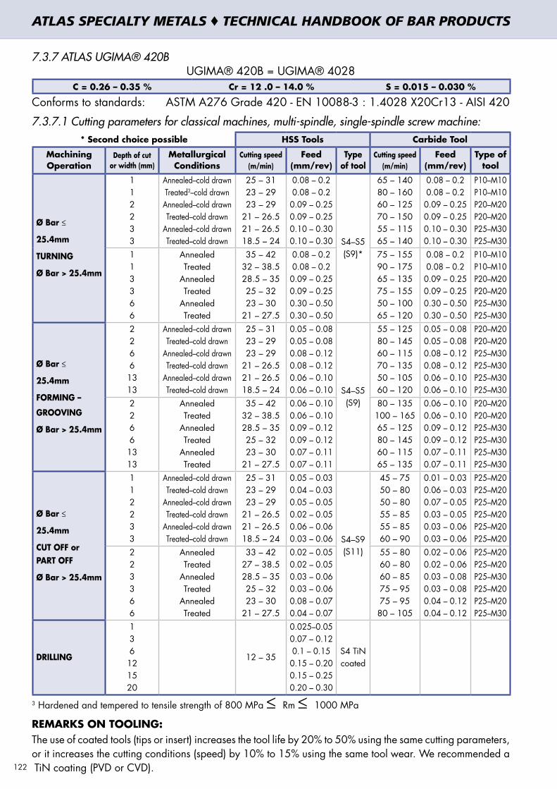
7.3.7 ATLAS UGIMA® 420BUGIMA® 420B = UGIMA® 4028
C = 0.26 – 0.35 % Cr = 12 .0 – 14.0 % S = 0.015 – 0.030 %
Conforms to standards: ASTM A276 Grade 420 - EN 10088-3 : 1.4028 X20Cr13 - AISI 420
7.3.7.1 Cutting parameters for classical machines, multi-spindle, single-spindle screw machine:* Second choice possible HSS Tools Carbide Tool
Machining Operation
Depth of cut or width (mm)
Metallurgical Conditions
Cutting speed (m/min)
Feed (mm/rev)
Type of tool
Cutting speed (m/min)
Feed (mm/rev)
Type of tool
Ø Bar ≤
25.4mm
TURNING
Ø Bar > 25.4mm
112233
Annealed–cold drawnTreated3–cold drawn
Annealed–cold drawnTreated–cold drawn
Annealed–cold drawnTreated–cold drawn
25 – 3123 – 2923 – 29
21 – 26.521 – 26.518.5 – 24
0.08 – 0.20.08 – 0.20.09 – 0.250.09 – 0.250.10 – 0.300.10 – 0.30 S4–S5
(S9)*
65 – 14080 – 16060 – 12570 – 15055 – 11565 – 140
0.08 – 0.20.08 – 0.20.09 – 0.250.09 – 0.250.10 – 0.300.10 – 0.30
P10–M10P10–M10P20–M20P20–M20P25–M30P25–M30
113366
AnnealedTreated
AnnealedTreated
AnnealedTreated
35 – 4232 – 38.528.5 – 3525 – 3223 – 30
21 – 27.5
0.08 – 0.20.08 – 0.20.09 – 0.250.09 – 0.250.30 – 0.500.30 – 0.50
75 – 15590 – 17565 – 13575 – 15550 – 10065 – 120
0.08 – 0.20.08 – 0.20.09 – 0.250.09 – 0.250.30 – 0.500.30 – 0.50
P10–M10P10–M10P20–M20P20–M20P25–M30P25–M30
Ø Bar ≤
25.4mm
FORMING –
GROOVING
Ø Bar > 25.4mm
22661313
Annealed–cold drawnTreated–cold drawn
Annealed–cold drawnTreated–cold drawn
Annealed–cold drawnTreated–cold drawn
25 – 3123 – 2923 – 29
21 – 26.521 – 26.518.5 – 24
0.05 – 0.080.05 – 0.080.08 – 0.120.08 – 0.120.06 – 0.100.06 – 0.10 S4–S5
(S9)
55 – 12580 – 14560 – 11570 – 13550 – 10560 – 120
0.05 – 0.080.05 – 0.080.08 – 0.120.08 – 0.120.06 – 0.100.06 – 0.10
P20–M20P20–M20P25–M30P25–M30P25–M30P25–M30
22661313
AnnealedTreated
AnnealedTreated
AnnealedTreated
35 – 4232 – 38.528.5 – 3525 – 3223 – 30
21 – 27.5
0.06 – 0.100.06 – 0.100.09 – 0.120.09 – 0.120.07 – 0.110.07 – 0.11
80 – 135100 – 16565 – 12580 – 14560 – 11565 – 135
0.06 – 0.100.06 – 0.100.09 – 0.120.09 – 0.120.07 – 0.110.07 – 0.11
P20–M20P20–M20P25–M30P25–M30P25–M30P25–M30
Ø Bar ≤
25.4mm
CUT OFF orPART OFF
Ø Bar > 25.4mm
112233
Annealed–cold drawnTreated–cold drawn
Annealed–cold drawnTreated–cold drawn
Annealed–cold drawnTreated–cold drawn
25 – 3123 – 2923 – 29
21 – 26.521 – 26.518.5 – 24
0.05 – 0.030.04 – 0.030.05 – 0.050.02 – 0.050.06 – 0.060.03 – 0.06 S4–S9
(S11)
45 – 7550 – 8050 – 8055 – 8555 – 8560 – 90
0.01 – 0.030.06 – 0.030.07 – 0.050.03 – 0.050.03 – 0.060.03 – 0.06
P25–M20P25–M20P25–M20P25–M20P25–M20P25–M20
2 23366
AnnealedTreated
AnnealedTreated
AnnealedTreated
33 – 4227 – 38.528.5 – 3525 – 3223 – 30
21 – 27.5
0.02 – 0.050.02 – 0.050.03 – 0.060.03 – 0.060.08 – 0.070.04 – 0.07
55 – 8060 – 8060 – 8575 – 9575 – 95
80 – 105
0.02 – 0.060.02 – 0.060.03 – 0.080.03 – 0.080.04 – 0.120.04 – 0.12
P25–M20P25–M20P25–M30P25–M20P25–M20P25–M30
DRILLING
136121520
12 – 35
0.025–0.050.07 – 0.120.1 – 0.150.15 – 0.200.15 – 0.250.20 – 0.30
S4 TiN coated
3 Hardened and tempered to tensile strength of 800 MPa ≤ Rm ≤ 1000 MPa
REMARKS ON TOOLING: The use of coated tools (tips or insert) increases the tool life by 20% to 50% using the same cutting parameters, or it increases the cutting conditions (speed) by 10% to 15% using the same tool wear. We recommended a TiN coating (PVD or CVD). 122
ATLAS SPECIALTY METALS ♦ TECHNICAL HANDBOOK OF BAR PRODUCTS

7.3.7.2 Cutting conditions for CNC machinery:Brazed Carbide
Uncoated Carbide Insert
Coated Carbide Insert
Machining Operation
Depth of cut or width (mm)
Metallurgic conditions
Cutting Speed (m/min)
Cutting Speed (m/min)
Cutting Speed (m/min)
Feed (mm/rev)
Type of Tool
Ø Bar ≤
25.4mm
TURNING
Ø Bar > 25.4mm
112233
Annealed -cold drawnTreated4 -cold drawn
Annealed -cold drawnTreated -cold drawn
Annealed -cold drawnTreated -cold drawn
65 – 14080 – 16060 – 12570 – 15055 – 11565 – 140
120 – 195145 – 205115 – 170125 – 185100 – 150120 – 170
140 – 195155 – 230125 – 175140 – 210115 – 155130 – 200
0.08 - 0.20.08 - 0.20.09–0.250.09–0.250.10–0.300.10–0.30
P10-M10P10-M10P20-M20P20-M20P25-M30P25-M30
1 13366
AnnealedTreated
AnnealedTreated
AnnealedTreated
75 – 15590 – 17565 – 13575 – 15550 – 10065 – 120
145 – 230185 – 240110 – 190130 – 20585 – 145
110 – 160
185 – 260230 – 325150 – 235190 – 270125 – 185170 – 230
0.08 - 0.20.08 - 0.20.09–0.250.09–0.250.30–0.500.30–0.50
P10-M10P10-M10P20-M20P20-M20P25-M30P25-M30
Ø Bar ≤
25.4mm
GROOVING
Ø Bar > 25.4mm
2266
Annealed -cold drawnTreated -cold drawn
Annealed -cold drawnTreated -cold drawn
55 – 12580 – 14560 – 11570 – 135
120 – 150130 – 18590 – 140
125 – 180
145 – 180170 – 210115 – 165130 – 185
0.07–0.150.07–0.150.10–0.250.10–0.25
P20-M20P20-M20P25-M30P25-M30
2266
AnnealedTreated
AnnealedTreated
80 – 135100 – 16565 – 12580 – 145
130 – 170150 – 18595 – 140
125 – 180
155 – 205180 – 230125 – 180150 – 210
0.08–0.170.06–0.170.12–0.250.12–0.25
P20-M20P20-M20P25-M30P25-M30
Ø Bar ≤
25.4mm
CUT-OFF or
PART OFF
Ø Bar > 25.4mm
112233
Annealed -cold drawnTreated -cold drawn
Annealed -cold drawnTreated -cold drawn
Annealed -cold drawnTreated -cold drawn
45 – 7550 – 8050 – 8055 – 8555 – 8560 – 90
65 – 10575 – 12575 – 12085 – 14085 – 120
105 – 150
70 – 11585 – 12575 – 12090 – 15585 – 12595 – 180
0.01–0.030.01–0.030.03–0.060.03–0.060.03–0.080.03–0.08
P25-M20P25-M20P25-M20P25-M20P25-M20P25-M20
2 23366
AnnealedTreated
AnnealedTreated
AnnealedTreated
55 – 8060 – 8060 – 8575 – 9575 – 9580 – 105
85 – 12090 – 15090 – 140
110 – 17095 – 150
115 – 185
95 – 150115 – 200110 – 170135 – 235115 – 175145 – 250
0.02–0.060.02–0.060.04–0.100.04–0.100.04–0.120.04–0.12
P25-M20P25-M20P25-M30P25-M20P25-M20P25-M30
4 Hardened and tempered to tensile strength of 700 MPa ≤ Rm ≤ 950 MPaHSS Drill type N Plain Carbide Drill
Machining Operation
Diameter (mm)
Cutting speed (m/min)
Feed (mm/rev)
Type of tool
Cutting Speed (m/min)
Feed (mm/rev)
Type of tool
DRILLING
136121520
10 – 40
0.025 – 0.050.12 – 0.200.19 – 0.270.25 – 0.320.28 – 0.350.32 – 0.40
S4 TiN Coated 80 – 180
0.025 – 0.050.05 – 0.120.05 – 0.150.10 – 0.250.13 – 0.270.15 – 0.30
P20 – P40 or K40
TiN coated
DRILLING: 1. The quality of the cutting lubricant is important. There must be a large quantity (pressure+steady flow) coming
through regularly. On the large drills, it is recommended to use drills with oil holes (internal lubrication).2. The cutting conditions recommended are valid for a depth of drilling equal to 4 x f maximum.3. We would advise you use drills with a pointed angle of approximately 118°.
LUBRICANT: We recommend lubricant with extreme pressure additives.
REMARKS ON THE TOOLING: For the type of coating of the coated carbide tips (inserts), we recommend those with a final visible layer of TiN, generally gold colour. 123
ATLAS SPECIALTY METALS ♦ TECHNICAL HANDBOOK OF BAR PRODUCTS

7.4 MACHININING OF ALUMINIUM ALLOYS
7.4.1 GENERAL INFORMATION
Aluminium is generally easier to machine than steel, because it is a much softer material. The machining of aluminium, compared to a steel grade of similar strength, takes 2 to 3 times less energy. Whilst the specific cutting force of medium carbon steels like M1020 or M1030 is 2000 – 2200 MPa, the specific cutting force of aluminium alloys Atlas 2011 and Atlas 6262 is 800 – 900 MPa. The low machining costs of aluminium hence make it an attractive material.
The relative softness of aluminium also creates problems in machining, such as the low chipability – the tendency to form long stringers of chips – and the ‘sticky’ behaviour – the tendency of aluminium part to stick to the cutting tool.
This build-up phenomenon is mostly present at low cutting speeds, when a false cutting edge of the cutting tool is formed by material sticking on to the tool. The build-up can be reduced by:
• increasing the surface speed, aluminium is very suitable for high-speed machining due to its high thermal conductivity • increasing the cutting angle to its maximum • using a lubrication that is suitable for aluminium • increase the feed rate
Ceramic cutting materials (i.e. Cermet) are not recommended for machining aluminium since the matrix of this material has a chemical affinity for the aluminium thus making it difficult to achieve a satisfactory operating life.
Whilst uncoated carbide inserts in grades K01 and K10 are recommended for machining aluminium machining bar, coated carbide inserts have proved to be unsatisfactory. Titanium compounds (TiN) are mostly used as coating material and titanium has a chemical affinity with aluminium. Therefore, titanium diffuses out of the hard coating so that this soon loses its effectiveness.
Tools made out of high-speed steels offer the following advantages: high toughness, high bending strength, ease of working, low price. Toughness is important, especially since the slim form of the cutting tool typically used for cutting aluminium has a higher tendency to break than tools with a negative geometry (as are typical for cutting steel). HSS tools suitable to be used with aluminium machining bar and an acceptable tool operating life can be achieved.
Diamond tools have substantially longer operating lives compared to carbide-tipped tools, but also higher precision and better operating stability. Currently polycrystalline diamond (PCD) tools are widely used for machining aluminium alloys. PCD tools have cutting properties which are much superior to those of carbide tools. Diamond tools also allow for extremely high machining speeds (Vc > 1000m/min).
As for machinability, aluminium alloys have been classified into four groups. The standard stock alloys marketed by Atlas Specialty Metals – 2011 and 6262 – are all part of group 2.
Group 2 consists of hardened aluminium alloys with Silicon content lower than 10%. Generally these alloys are very machinable due to their high hardness compared to other alluminium alloys. Depending on the alloy machining speeds vary from medium to high. All the alloys of group 2 are short-chipping.
124
ATLAS SPECIALTY METALS ♦ TECHNICAL HANDBOOK OF BAR PRODUCTS
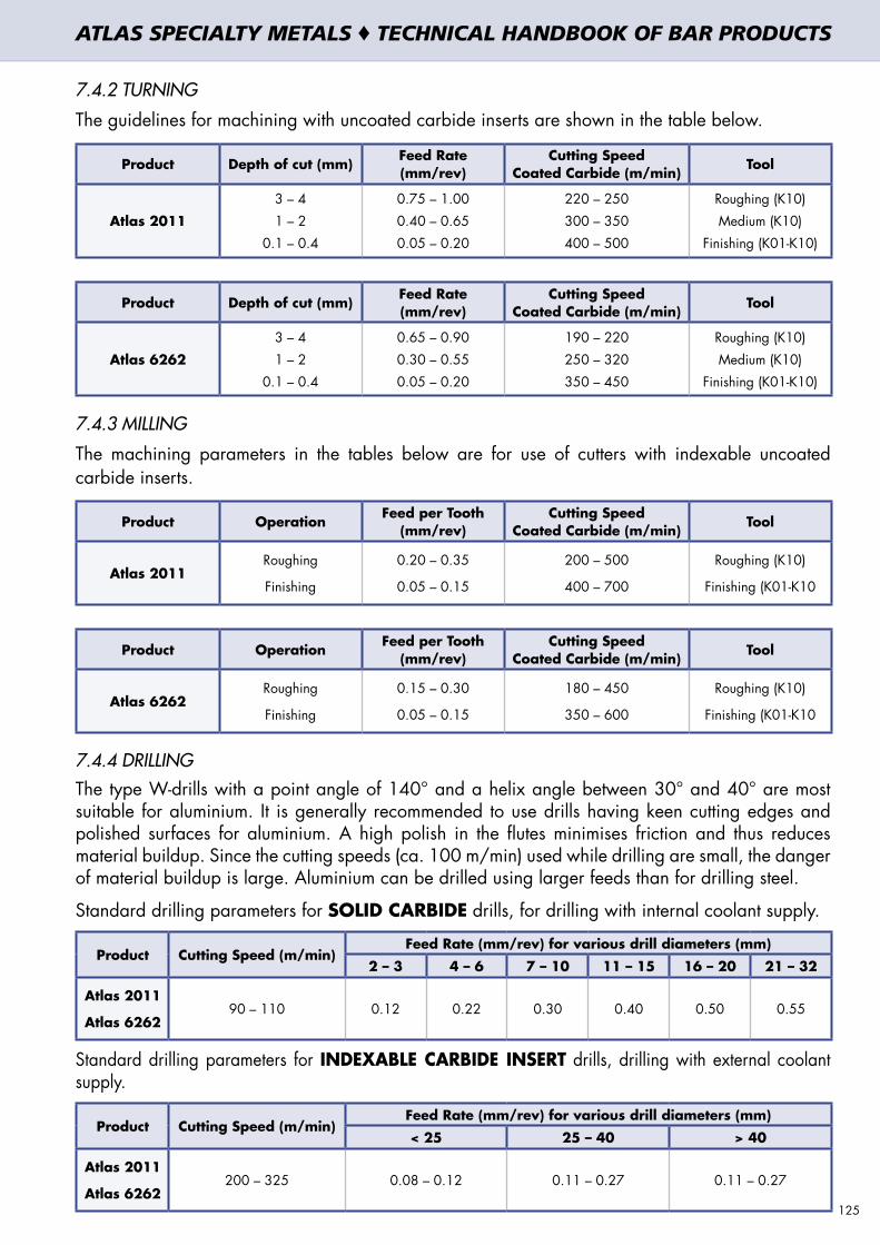
7.4.2 TURNING
The guidelines for machining with uncoated carbide inserts are shown in the table below.
Product Depth of cut (mm) Feed Rate (mm/rev)
Cutting SpeedCoated Carbide (m/min) Tool
Atlas 2011
3 – 4 1 – 2
0.1 – 0.4
0.75 – 1.000.40 – 0.650.05 – 0.20
220 – 250300 – 350400 – 500
Roughing (K10)Medium (K10)
Finishing (K01-K10)
Product Depth of cut (mm) Feed Rate (mm/rev)
Cutting SpeedCoated Carbide (m/min) Tool
Atlas 6262
3 – 41 – 2
0.1 – 0.4
0.65 – 0.900.30 – 0.550.05 – 0.20
190 – 220250 – 320350 – 450
Roughing (K10)Medium (K10)
Finishing (K01-K10)
7.4.3 MILLING
The machining parameters in the tables below are for use of cutters with indexable uncoated carbide inserts.
Product Operation Feed per Tooth (mm/rev)
Cutting SpeedCoated Carbide (m/min) Tool
Atlas 2011Roughing
Finishing
0.20 – 0.35
0.05 – 0.15
200 – 500
400 – 700
Roughing (K10)
Finishing (K01-K10
Product Operation Feed per Tooth (mm/rev)
Cutting SpeedCoated Carbide (m/min) Tool
Atlas 6262Roughing
Finishing
0.15 – 0.30
0.05 – 0.15
180 – 450
350 – 600
Roughing (K10)
Finishing (K01-K10
7.4.4 DRILLINGThe type W-drills with a point angle of 140° and a helix angle between 30° and 40° are most suitable for aluminium. It is generally recommended to use drills having keen cutting edges and polished surfaces for aluminium. A high polish in the flutes minimises friction and thus reduces material buildup. Since the cutting speeds (ca. 100 m/min) used while drilling are small, the danger of material buildup is large. Aluminium can be drilled using larger feeds than for drilling steel.
Standard drilling parameters for SOLID CARBIDE drills, for drilling with internal coolant supply.
Product Cutting Speed (m/min)Feed Rate (mm/rev) for various drill diameters (mm)
2 – 3 4 – 6 7 – 10 11 – 15 16 – 20 21 – 32
Atlas 2011
Atlas 626290 – 110 0.12 0.22 0.30 0.40 0.50 0.55
Standard drilling parameters for INDEXABLE CARBIDE INSERT drills, drilling with external coolant supply.
Product Cutting Speed (m/min)Feed Rate (mm/rev) for various drill diameters (mm)
< 25 25 – 40 > 40
Atlas 2011
Atlas 6262200 – 325 0.08 – 0.12 0.11 – 0.27 0.11 – 0.27
125
ATLAS SPECIALTY METALS ♦ TECHNICAL HANDBOOK OF BAR PRODUCTS


5. NON-DESTRUCTIVE TESTING OF ATLAS BAR PRODUCTS5. NON-DESTRUCTIVE TESTING OF ATLAS BAR PRODUCTS 8. TECHNICAL DATA8. TECHNICAL DATA


8.1 DIMENSIONAL TOLERANCES
AS 1654 / ISO 286 nominal size tolerances for round bar (µm)
Nominal Bar Diameter (mm)
Tolerance Grade
Over 3
Over 6
Over 10
Over 18
Over 30
Over 50
Over 80
Over 120
Over 180
Over 250
Over 315
Over 400
IT
Up To 3 Up To
6Up To
10Up To
18Up To
30Up To
50Up To
80Up To 120
Up To 180
Up To 250
Up To 315
Up To 400
Up To 500
5
6
7
4
6
10
5
8
12
6
9
15
8
11
18
9
13
21
11
16
25
13
19
30
15
22
35
18
25
40
20
29
46
23
32
52
25
36
57
27
40
63
8
9
10
14
25
40
18
30
48
22
36
58
27
43
70
33
52
84
39
62
100
46
74
120
54
87
140
63
100
160
72
115
185
81
130
210
89
140
230
97
155
250
11
12
13
60
100
140
75
120
180
90
150
220
110
180
270
130
210
330
160
250
390
190
300
460
220
350
540
250
400
630
290
460
720
320
520
810
360
570
890
400
630
970
14
15
16
250
400
600
300
480
750
360
580
900
430
700
1100
520
840
1300
620
1000
1600
740
1200
1900
870
1400
2200
1000
1600
2500
1150
1850
2900
1300
2100
3200
1400
2300
3600
1550
2500
4000
ATLAS SPECIALTY METALS ♦ TECHNICAL HANDBOOK OF BAR PRODUCTS
Example: Nominal Bar Diameter = 45mm
Note: k tolerances are according to the above table between k8 and k13 only.
"h" is a minus tolerance
"js" is an even tolerance
"k" is a plus tolerance
Example 1: 45mm h8Max. diameter = 45.000mmMin. diameter = 44.961mm
Example 2: 45mm js10Max. diameter = 45.050mmMin. diameter = 44.950mm
Example 3: 45mm k12Max. diameter = 45.25mmMin. diameter = 45.000mm
129

8.2 METRIC – IMPERIAL CONVERSION CHART
INCHES METRIC INCHES METRIC INCHES METRIC
FRACTIONAL DECIMAL mm FRACTIONAL DECIMAL mm FRACTIONAL DECIMAL mm
. 0.0039 0.1000 . 0.1969 5.0000 . 0.5512 14.0000
. 0.0079 0.2000 13/64 0.2031 5.1594 9/16 0.5625 14.2875
. 0.0118 0.3000 . 0.2165 5.5000 . 0.5709 14.5000
1/64 0.0156 0.3969 7/32 0.2188 5.5563 37/64 0.5781 14.6844. 0.0157 0.4000 15/64 0.2344 5.9531 . 0.5906 15.0000. 0.0197 0.5000 . 0.2362 6.0000 19/32 0.5938 15.0813. 0.0236 0.6000 . 0.2500 6.3500 39/64 0.6094 15.4781. 0.0276 0.7000 . 0.2559 6.5000 . 0.6102 15.5000
1/32 0.0313 0.7938 17/64 0.2656 6.7469 5/8 0.6250 15.8750. 0.0315 0.8000 . 0.2756 7.0000 . 0.6299 16.0000. 0.0354 0.9000 9/32 0.2813 7.1438 41/64 0.6406 16.2719. 0.0394 1.0000 . 0.2953 7.5000 . 0.6496 16.5000. 0.0433 1.1000 19/64 0.2969 7.5406 21/32 0.6563 16.6688
3/64 0.0469 1.1906 5/16 0.3125 7.9375 . 0.6693 17.0000. 0.0472 1.2000 . 0.3150 8.0000 43/64 0.6719 17.0656. 0.0512 1.3000 21/64 0.3281 8.3344 11/16 0.6875 17.4625. 0.0551 1.4000 . 0.3346 8.5000 . 0.6890 17.5000. 0.0591 1.5000 11/32 0.3438 8.7313 45/64 0.7031 17.8594
1/16 0.0625 1.5875 . 0.3543 9.0000 . 0.7087 18.0000. 0.0630 1.6000 23/64 0.3594 9.1281 23/32 0.7188 18.2563. 0.0669 1.7000 . 0.3740 9.5000 . 0.7283 18.5000. 0.0709 1.8000 3/8 0.3750 9.5250 47/64 0.7344 18.6531. 0.0748 1.9000 25/64 0.3906 9.9219 . 0.7480 19.0000
5/64 0.0781 1.9844 . 0.3937 10.0000 3/4 0.7500 19.0500. 0.0787 2.0000 13/32 0.4063 10.3188 49/64 0.7656 19.4469. 0.0827 2.1000 . 0.4134 10.5000 . 0.7677 19.5000. 0.0866 2.2000 27/64 0.4219 10.7156 25/32 0.7813 19.8438. 0.0906 2.3000 . 0.4331 11.0000 . 0.7874 20.0000
3/32 0.0938 2.3813 7/16 0.4375 11.1125 51/64 0.7969 20.2406. 0.0945 2.4000 . 0.4528 11.5000 . 0.8071 20.5000. 0.0984 2.5000 29/64 0.4531 11.5094 13/16 0.8125 20.6375
7/64 0.1094 2.7781 15/32 0.4688 11.9063 . 0.8268 21.0000. 0.1181 3.0000 . 0.4724 12.0000 53/64 0.8281 21.0344
1/8 0.1250 3.1750 31/64 0.4844 12.3031 27/32 0.8438 21.4313. 0.1378 3.5000 . 0.4921 12.5000 . 0.8465 21.5000
9/64 0.1406 3.5719 1/2 0.5000 12.7000 55/64 0.8594 21.8281
5/32 0.1563 3.9688 . 0.5118 13.0000 . 0.8661 22.0000. 0.1575 4.0000 33/64 0.5156 13.0969 7/8 0.8750 22.2250
11/64 0.1719 4.3656 17/32 0.5313 13.4938 . 0.8858 22.5000. 0.1772 4.5000 . 0.5315 13.5000 57/64 0.8906 22.6219
3/16 0.1875 4.7625 35/64 0.5469 13.8906 . 0.9055 23.0000130
ATLAS SPECIALTY METALS ♦ TECHNICAL HANDBOOK OF BAR PRODUCTS
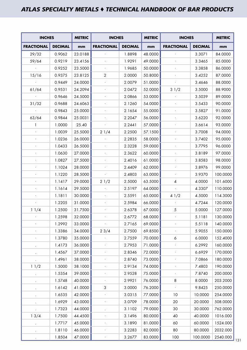
131
INCHES METRIC INCHES METRIC INCHES METRIC
FRACTIONAL DECIMAL mm FRACTIONAL DECIMAL mm FRACTIONAL DECIMAL mm
29/32 0.9062 23.0188 . 1.8898 48.0000 . 3.3071 84.0000
59/64 0.9219 23.4156 . 1.9291 49.0000 . 3.3465 85.0000. 0.9252 23.5000 . 1.9685 50.0000 . 3.3858 86.0000
15/16 0.9375 23.8125 2 2.0000 50.8000 . 3.4252 87.0000. 0.9449 24.0000 . 2.0079 51.0000 . 3.4646 88.0000
61/64 0.9531 24.2094 . 2.0472 52.0000 3 1/2 3.5000 88.9000. 0.9646 24.5000 . 2.0866 53.0000 . 3.5039 89.0000
31/32 0.9688 24.6063 . 2.1260 54.0000 . 3.5433 90.0000. 0.9843 25.0000 . 2.1654 55.0000 . 3.5827 91.0000
63/64 0.9844 25.0031 . 2.2047 56.0000 . 3.6220 92.0000
1 1.0000 25.40 . 2.2441 57.0000 . 3.6614 93.0000. 1.0039 25.5000 2 1/4 2.2500 57.1500 . 3.7008 94.0000. 1.0236 26.0000 . 2.2835 58.0000 . 3.7402 95.0000. 1.0433 26.5000 . 2.3228 59.0000 . 3.7795 96.0000. 1.0630 27.0000 . 2.3622 60.0000 . 3.8189 97.0000. 1.0827 27.5000 . 2.4016 61.0000 . 3.8583 98.0000. 1.1024 28.0000 . 2.4409 62.0000 . 3.8976 99.0000. 1.1220 28.5000 . 2.4803 63.0000 . 3.9370 100.0000. 1.1417 29.0000 2 1/2 2.5000 63.5000 4 4.0000 101.6000. 1.1614 29.5000 . 2.5197 64.0000 . 4.3307 110.0000. 1.1811 30.0000 . 2.5591 65.0000 4 1/2 4.5000 114.3000. 1.2205 31.0000 . 2.5984 66.0000 . 4.7244 120.0000
1 1/4 1.2500 31.7500 . 2.6378 67.0000 5 5.0000 127.0000. 1.2598 32.0000 . 2.6772 68.0000 . 5.1181 130.0000. 1.2992 33.0000 . 2.7165 69.0000 . 5.5118 140.0000. 1.3386 34.0000 2 3/4 2.7500 69.8500 . 5.9055 150.0000. 1.3780 35.0000 . 2.7559 70.0000 6 6.0000 152.4000
. 1.4173 36.0000 . 2.7953 71.0000 . 6.2992 160.0000
. 1.4567 37.0000 . 2.8346 72.0000 . 6.6929 170.0000
. 1.4961 38.0000 . 2.8740 73.0000 . 7.0866 180.0000
1 1/2 1.5000 38.1000 . 2.9134 74.0000 . 7.4803 190.0000
. 1.5354 39.0000 . 2.9528 75.0000 . 7.8740 200.0000
. 1.5748 40.0000 . 2.9921 76.0000 8 8.0000 203.2000
. 1.6142 41.0000 3 3.0000 76.2000 . 9.8425 250.0000
. 1.6535 42.0000 . 3.0315 77.0000 10 10.0000 254.0000
. 1.6929 43.0000 . 3.0709 78.0000 20 20.0000 508.0000
. 1.7323 44.0000 . 3.1102 79.0000 30 30.0000 762.0000
1 3/4 1.7500 44.4500 . 3.1496 80.0000 40 40.0000 1016.000
. 1.7717 45.0000 . 3.1890 81.0000 60 60.0000 1524.000
. 1.8110 46.0000 . 3.2283 82.0000 80 80.0000 2032.000
. 1.8504 47.0000 . 3.2677 83.0000 100 100.0000 2540.000
ATLAS SPECIALTY METALS ♦ TECHNICAL HANDBOOK OF BAR PRODUCTS

Brinell HB
Vickers HV
Rockwell HRC
Tensile Strength MPa
100 105 335
105 110 350
110 115 373
115 120 388
120 126 403
125 131 418
130 137 438
135 142 456
140 147 471
145 152 488
150 158 504
155 163 525
160 168 539
165 173 557
170 179 572
175 184 591
180 189 607
185 194 625
190 200 640
195 205 660
200 210 678
205 215 693
210 221 708
215 226 724
220 231 744
225 236 761
230 242 20.7 776
235 247 21.7 791
240 252 22.7 810
245 257 23.7 827
250 263 24.5 844
255 268 25.3 859
260 273 26.2 877
265 278 26.9 896
270 284 27.6 912
275 289 28.4 927
280 294 29.2 950
285 300 29.8 965
290 305 30.5 980
295 310 31.0 995
300 315 31.6 1015
305 321 32.3 1033
310 326 32.8 1048
315 331 33.4 1063
320 336 34.0 1083
325 341 34.6 1101
330 346 35.2 1116
335 352 35.7 1131
340 357 36.3 1149
Brinell HB
Vickers HV
Rockwell HRC
Tensile Strength MPa
340 357 36.3 1149
345 362 37.0 1165
350 367 37.5 1183
355 373 38.1 1201
360 378 38.7 1217
365 384 39.2 1234
370 389 39.7 1251
370 389 39.7 1251
375 394 40.2 1271
380 400 40.8 1290
385 405 41.3 1305
390 410 41.8 1320
395 415 42.3 1338
400 421 42.8 1353
405 426 43.3 1371
410 431 43.7 1389
415 436 44.2 1407
420 442 44.7 1427
425 447 45.1 1445
430 452 45.4 1461
435 457 45.9 1478
440 463 46.4 1494
445 468 46.7 1512
450 473 47.1 1532
455 478 47.6 1550
460 484 47.9 1571
465 489 48.3 1591
470 494 48.6 1611
475 500 49.1 1630
480 505 49.5 1644
485 510 49.8 1665
490 515 50.2 1685
495 521 50.5 1704
500 526 50.8 1724
505 531 51.1 1744
510 536 51.5 1764
515 542 51.8 1782
520 547 52.0 1801
525 552 52.4 1818
530 557 52.8 1838
535 563 53.1 1855
540 568 53.4 1873
545 573 53.7 1893
550 578 54.0 1916
555 584 54.3 1934
560 589 54.6 1952
565 594 54.9 1973
570 600 55.2 1995
575 605 55.4 2013
Brinell HB
Vickers HV
Rockwell HRC
Tensile Strength MPa
580 610 55.7 2030
585 615 55.9 2052
590 621 56.3 2073
595 626 56.6 2091
600 631 56.8 2109
605 636 57.1 2132
610 642 57.4 2152
615 647 57.6 2169
655 58.0
660 58.3
665 58.5
670 58.8
675 59.0
680 59.2
685 59.4
690 59.7
695 59.9
700 60.1
705 60.3
710 60.5
715 60.8
720 61.0
725 61.2
730 61.5
735 61.6
740 61.8
745 61.9
750 62.1
755 62.2
760 62.5
765 62.6
770 62.8
780 63.3
790 63.6
800 64.0
810 64.4
820 64.7
830 65.0
835 65.1
840 65.3
850 65.6
860 65.9
870 66.1
880 66.4
890 66.6
900 67.0
910 67.2
920 67.5
930 67.7
8.3 HARDNESS CONVERSION TABLE – CARBON & LOW ALLOY STEELS
ATLAS SPECIALTY METALS ♦ TECHNICAL HANDBOOK OF BAR PRODUCTS
132
Not
e: C
onve
rsio
ns b
etw
een
hard
ness
sca
les
and
parti
cula
ry c
onve
rsio
ns b
etw
een
hard
ness
and
tens
ile s
treng
th a
re a
ppro
xim
ate
only.
Th
ese
conv
ersio
ns s
houl
d no
t be
used
to d
eter
min
e co
mpl
ianc
e w
ith s
peci
ficat
ions
. Thi
s ta
ble
does
not
app
ly to
aus
teni
fic s
tain
less
ste
els.

PRINTED: JANUARY 2005 – EDITION #1
LIMITATION OF LIABILITY
The information contained in this Handbook is not intended to be an exhaustive statement of all relevant data applicable to special and general steel products. It has been designed as a guide for customers of Atlas Specialty Metals. No responsibility is implied or accepted for or in conjunction with quality or standard of any product or its suitability for any purpose or use.
It is the responsibility of the user to ensure product specified is fit for the purpose intended.
All conditions, warranties, obligations and liabilities of any kind which are or may be implied or imposed to the contrary by any statute, rule or regulation or under the general law and whether arising from the negligence of the Company, its servants or otherwise are hereby excluded except to the extent that the Company may be prevented by any statute, rule or regulation from doing so.
Published by Atlas Specialty Metals Technical Services Department
Copyright © Atlas Specialty Metals
“….you know mate, developing and innovating my products is ongoing; so is the support of my supplier” Nat Prendergast
Prendergast Fasteners Pty LtdQueensland

At
las
Sp
ec
ialt
y M
et
als
– T
ec
hn
ica
l Ha
nd
bo
ok
of
Ba
r P
ro
du
ct
s
The Atlas Specialty Metals
Technical Handbook
of
Bar Products
www.atlasmetals.com.au
ATLAS SPECIALTY METALSTECHNICAL SERVICES DEPARTMENT
Copyright © Atlas Specialty Metals Technical Assistance: Freecall 1800 818 599 Revised: January 2005 Email: [email protected]
www.atlasmetals.com.auTECHNICAL SERVICES 1800 818 599 Email: [email protected]
PROJECT SERVICES (03) 9272 9999 Email: [email protected]
ATLAS SPECIALTY METALS