atis/sip forum routing outline · web viewthe existing industry framework supports the evolution of...
TRANSCRIPT
IPNNI- 2014-00083R14
ContributionTITLE: IP Interconnection Routing Report
SOURCE*: Editor
_______________________________
ABSTRACTThis document provides a marked up version of the changes agreed to at the IP NNI Task Force 9/30/2014 Meeting.
Contributions Added:
IPNNI-2014-00097R000 IPNNI-2014-00100R001
NOTICE-------------------------------------------------------------------------------------------------------------------------------------------------------
This is a draft document and thus, is dynamic in nature. It does not reflect a consensus of the ATIS-SIP Forum IP-NNI Task Force and it may be changed or modified. Neither ATIS nor the SIP Forum makes any representation or warranty, express or implied, with respect to the sufficiency, accuracy or utility of the information or opinion contained or reflected in the material utilized. ATIS and the SIP Forum further expressly advise that any use of or reliance upon the material in question is at your risk and neither ATIS nor the SIP Forum shall be liable for any damage or injury, of whatever nature, incurred by any person arising out of any utilization of the material. It is possible that this material will at some future date be included in a copyrighted work by ATIS or the SIP Forum.
-------------------------------------------------------------------------------------------------------------------------------------------------------
* CONTACT:
Rebecca Goodman, [email protected], 202-434-8839
Gary Richenaker; email: [email protected]; Tel: +1 732-699-4705

ATIS-1000062
Technical Report on
IP Interconnection Routing
Alliance for Telecommunications Industry Solutions
Approved Month DD, YYYY
Abstract
As Service Providers introduce and expand IP-based service offerings, there is increasing interest in identifying the opportunities for the industry to facilitate IP routing of VoIP traffic using E.164 addresses. The ATIS/SIP Forum IP-NNI Task Force has taken on the initiative to develop a Technical Document and is publishing a draft report to describe the candidate proposals for circulation and comment. Recognizing that IP traffic exchange is developing as an overlay to existing TDM interconnection and will be implemented by different service providers with varying timelines, the purpose of this draft report is to:
1. Provide an overview of in-use and proposed architectures with the provisioning processes and calls flows to facilitate the exchange of VoIP traffic associated with IP-based services using E.164 addresses.
2. Present comparative characteristics that may be useful in understanding the approaches.3. Consider how such in use and proposed solution(s) may be adopted and/or coexist, and evolve for transition
to a future integrated registry envisioned at the FCC Numbering Testbed Workshop.

ATIS-1000062
ForewordThe Alliance for Telecommunications Industry Solutions (ATIS) serves the public through improved understanding between carriers, customers, and manufacturers. The [COMMITTEE NAME] Committee [INSERT MISSION]. [INSERT SCOPE].
The SIP Forum’s mission is to advance the adoption of products and services based on the Session Initiation Protocol and to maintain and serve a global community of commercial SIP based service and technology providers. The primary goals of the SIP Forum are to foster interoperability and adherence to standardization efforts, and provide educational resources and a platform for productive communication among industry participants.
This document was developed by the ATIS/SIP Forum IP-NNI Task Force
Suggestions for improvement of this document are welcome. They should be sent to the Alliance for Telecommunications Industry Solutions, [COMMITTEE NAME], 1200 G Street NW, Suite 500, Washington, DC 20005.
At the time of consensus on this document, [COMMITTEE NAME], which was responsible for its development, had the following leadership:
[LEADERSHIP LIST]
The [SUBCOMMITTEE NAME] Subcommittee was responsible for the development of this document.
i

ATIS-1000062
Table of Contents[INSERT]
Table of Figures[INSERT]
Table of Tables
[INSERT]
ii
TECHNICAL REPORT ATIS-1000062
Technical Report on –
IP Interconnection Routing
1 Scope, Purpose, & Application1.1 ScopeThis document was developed under a joint ATIS/SIP Forum collaboration. The document discusses existing in-use and proposed routing solutions to facilitate the exchange of traffic associated with IP-based services between North American service providers.
Many options and issues were previously investigated by an ATIS Inter-Carrier VoIP Call Routing Focus Group (IVCR-FG), which issued its final report in February 2008. At that time, the IVCR-FG report noted that a number of vendor proposals have been made, but no initiative exists to develop the necessary standards needed to enable VoIP call interconnectivity [1].
The initial objectives of the ATIS/SIP Forum IP-NNI Task Force as memorialized in the agreement between ATIS and the SIP Forum included defining “the architecture and requirements for a shared “Thin” registry of NNI interconnection data.” The Task Force was unable to reach consensus on a single registry architecture. Accordingly, this report summarizes the various proposals for IP interconnection routing that have been discussed by the Task Force, both registry and non-registry based, and how they may interoperate.
Subsequent to the formation of the ATIS/SIP Forum IP-NNI Task Force, the Federal Communications Commission authorized the creation of a Numbering Testbed to “spur the research and development of the next generation standards and protocols for number allocation, verification, and call routing.”[2] The Commission also held a workshop to initiate a Numbering Testbed on March 25, 2014. Discussion at the Workshop focused on ideas for a “future integrated registry” that would support number allocation, verification, and call routing across all types of NANP numbers in a post TDM environment.
It should be noted that this initial report of the ATIS/SIP Forum IP-NNI Task Force report does not address the development of such an integrated registry, but instead focuses on the identification of existing in-use and proposed solutions to facilitate call routing across IP interconnections between now and the deployment of the future integrated registry envisioned at the Workshop.
1.2 PurposeAs Service Providers introduce and expand IP-based service offerings, there is increasing interest in identifying the opportunities for the industry to facilitate IP routing of VoIP traffic using E.164 addresses. The ATIS/SIP Forum IP-NNI Task Force has taken on the initiative to develop a Technical Report and is publishing a draft report to describe the candidate proposals for circulation and comment. Recognizing that IP traffic exchange is developing as an overlay to existing TDM interconnection and will be implemented by different service providers with varying timelines, the purpose of this draft report is to:
1. Provide an overview of in-use and proposed architectures with the provisioning processes and calls flows to facilitate the exchange of VoIP traffic associated with IP-based services using E.164 addresses.
2. Present comparative characteristics that may be useful in understanding the approaches.3. Consider how such in use and proposed solution(s) may be adopted and/or coexist, and evolve for
transition to a future integrated registry envisioned at the FCC Workshop.
Based upon the output and feedback on this draft report, further analysis will be required including but not limited to:
1. Refine solution(s) that includes consideration of feedback obtained from the draft report.
1

ATIS-10000622. Detail how existing in-use and proposed interim solution(s) may be adopted and/or coexist, and evolve.3. Finalize comparative characteristics
1.3 ApplicationThis is a Technical Report.
2 ReferencesThe following standards contain provisions which, through reference in this text, constitute provisions of this Standard. At the time of publication, the editions indicated were valid. All standards are subject to revision, and parties to agreements based on this Standard are encouraged to investigate the possibility of applying the most recent editions of the standards indicated below.
[1] ATIS-I-0000017, ATIS Inter-Carrier VoIP Call Routing (IVCR) Assessment and Work Plan, February 2008
[X] FCC 14-5, January 2013
[2] ATIS-0x0000x, Technical Report.
[3] ATIS-0x0000x.201x, American National Standard.
[4] ATIS-1000039
[5] RFC 4904
[6] RFC 4694
[7] RFC 6116
[8] RFC 5067
3 Definitions, Acronyms, & AbbreviationsFor a list of common communications terms and definitions, please visit the ATIS Telecom Glossary, which is located at < http://www.atis.org/glossary >.
3.1 DefinitionsFor the purposes of this document the following descriptions apply
3.1.1 The Business Integrated Routing and Rating Database System (BIRRDS)- is a database system used for inputting service provider call routing/rating and interconnection information for all telephone numbers within the North American numbering plan. BIRRDS data is entered by Service Providers (SPs) and/or their agents. It consists of a collection of input databases from which the LERG™ Routing Guide is generated.
3.1.2 LERG™ Routing Guide - is the North American telecom industry's recognized, authoritative database used for the exchange of PSTN routing information that is obtained from BIRRDS.
3.1.3 Common Language® CLONES Database – is the authoritative database used for the development and exchange of Common Language Location Codes (CLLITM Codes) per ATIS-0300253, Identification of Location Entities for the North American Telecommunications System. CLONES reference data is used in BIRRDS/LERG for the identification of switch and interface locations.
3.1.4 NPAC –is the authoritative industry PSTN database for local number portability routing information as mandated by the FCC in 1996. It is currently administered by Neustar who was awarded the initial contract by the FCC. NPAC is governed by the NANC/LNPA Working Group which is a Federal Advisory Committee to the FCC.
2

ATIS-1000062
3.2 Acronyms & Abbreviations 3GPP 3rd Generation Partnership Project
ALG Application Level Gateway
ATCF Access Transfer Control Function
B2BUA Back to Back user agent
BIRRDS Business Integrated Routing and Rating Database System
BGCF Border Gateway Control Function
CSCF Call Session Control Function
GSM Global System for Mobile
IBCF Interconnection Border Control Function
I-BGF Interconnection Border Gateway Function
I-CSCF Interrogating-Call Session Control Function
ICSS IMS Centralized Services
II-NNI Inter-IMS Network to Network Interface
IM-CN IP Multimedia Core Networks
IMS IP Multimedia Subsystem
IMS-ALG Multimedia Subsystem Application Level Gateway
IP Internet Protocol
IPSec IP Security
IPv4 Internet Protocol Version 4
IPv6 Internet Protocol Version 6
LERG Local Exchange Routing Guide
LTE Long-Term Evolution
MGCF Media Gateway Control Function
MGF Media Gateway Function
MIME Multipurpose Internet Mail Extensions
MSC Mobile Switching Center
NAT Network Address Translation
NAT-PT Network Address Translation—Protocol Translation
NECA National Exchange Carriers Association
NNI Network to Network Interface
NPAC Number Portability Administration Center
OCN Operating Company Number
P-CSCF Proxy Call Session Control Function
PE Provider Edge
RTP Real-Time Protocol
SBC Session Border Controller3

ATIS-1000062S-CSCF Serving-Call Session Control Function
SCTP Stream Control Transmission Protocol
SDP Session Description Protocol
SGF Signalling Gateway Function
SIP Session Initiation Protocol
SIP URI SIP protocol Uniform Resource Identifier
SIP-I SIP with encapsulated ISUP
SIP-T SIP for Telephones
SLA Service Level Agreement
SPID Service Provider ID
SRVCC Single Radio Voice Call Continuity
TCP Transmission Control Protocol
tel-URI Telephone Uniform Resource Identifier
TRF Transit and Roaming Function
TrGw Transition Gateway
TLS Transport Layer Security
UA User Agent
UDP User Datagram Protocol
UMTS Universal Mobile Telecommunications System
URI Uniform Resource Identifier
VoIP Voice over IP
VoLTE Voice of LTE
4 Aggregate Approaches Based on Existing NANP Data Structures
Some service providers are already exchanging voice traffic over IP facilities. This section details how routing for such exchanges has been implemented based on existing data in the LERG and NPAC supplemented with the bilateral exchange of information to map LERG and/or NPAC identifiers to IP connection information.
Existing approaches to IP interconnection routing discussed in this Section rely on NANP constructs that already aggregate telephone numbers into groups and then associate a route (SBC URI or IP address) with the TN group. Common methods of aggregation are Location Routing Number (LRN) in the NPAC, and OCNs, CLLIs, and central office codes (NPA-NXXs) in the LERG.
4.1 In-Use Method Using Existing LERG & NPAC Data4.1.1 IntroductionThis section describes how some SPs have already implemented an internal IP routing service using data available from the LERG and NPAC. This is possible because when SPs obtain numbering resources they are associated with the SP’s OCN, the serving switch’s CLLI code, an NPA-NXX, as well as a 10-digit LRN for those TNs which are ported or pooled. These “identifiers” are shared among SPs through existing NPAC and LERG feeds and no new industry systems development or standards were required to implement this solution. Sometimes referred to as the “aggregation method,” the use of these existing identifiers to efficiently represent (or
4

ATIS-1000062aggregate) large groups of TNs significantly reduces the quantity of routing records, and avoids the need for SPs to provision multiple instances of the same routing data for each of its customers’ TNs. During the development of the interconnection agreement, SPs exchange these “identifiers” (aka “TN group identifiers”) and ingress SBC IP addresses to establish routes between their networks via an IP interconnection.
4.1.2 Use CasesThe makeup of an SP’s switching infrastructure and the degree to which customer TNs are served via IP will influence which identifier(s) may be used to represent the groups of TNs to which traffic should be sent via an IP interconnect. The following use case examples are not intended to serve as an exhaustive list of possible scenarios:
A SP may specify calls to all of their customers’ TNs on all of their switches should be sent over an IP interconnection. Here, the SP can simply specify their Operating Company Number (OCN) as the identifier since all the TNs associated in the LERG and NPAC with their switches are related to their OCN. This is likely attractive if the SP is a VoIP provider or a cable company if all of their customers are served via IP.
If an SP has specific switches to which calls should be sent via IP, they could simply identify those switches by their switch CLLI code. This is likely attractive for SPs with a mixed TDM and IP switching infrastructure that prefer traffic associated with certain or all of their IP switches be sent via an IP interconnect. Also, SPs transitioning their TDM interconnects to IP can manage the rate of transition by adding switch CLLI codes to the list of identifiers as it grows its IP interconnection capacity.
The 10-digit LRN is a flexible vehicle for identifying a subset of TNs associated with a particular switch that, for example, serves both TDM and IP customer endpoints. Although SPs are required to establish at least one LRN per switch per LATA, they can create additional 10-digit LRNs to uniquely identify those TNs to which calls should be sent over an IP interconnection. This is likely attractive where one IP switch is used to serve both TDM and IP customer endpoints where the SP establishes second unique LRN to identify those TNs served via IP for which traffic should be sent over the IP interconnection. For example, an LTE wireless carrier may choose to establish unique LRNs to identify TNs belonging to VoLTE customers. Another example is where a CLEC provides TNs to an OTT VoIP provider and creates a unique LRN to identify those TNs assigned to customers of the OTT VoIP provider (that should be sent via and IP interconnection).
Below is a table summarizing the group of TNs represented by a “group identifier” as described in the above examples:
Group Identifier Group of TNs Represented By the Identifier
OCN All TNs associated with all SP switches
Switch CLLI All TNs associated with an single SP’s switch
LRN A subset of TNs associated with a single switch
NPA-NXX A subset of TNs associated with a single switch
4.1.3 ImplementationMany SP core networks are IP based and utilize an internal “routing service” to determine how to forward service requests. SIP redirect and DNS capabilities common in IP core networks provide the basic building blocks to implement real-time call processing for external NNI routing applications using “group identifiers.” This solution can be accommodated by commercially available routing (DNS and ENUM) infrastructure and each SP is free to determine when and how to implement a "routing service” solution appropriate for their business and operational needs. SPs have options given vendors are actively engaged in providing solutions of this nature and the following general description is provided for illustrative purposes only.
5

ATIS-1000062
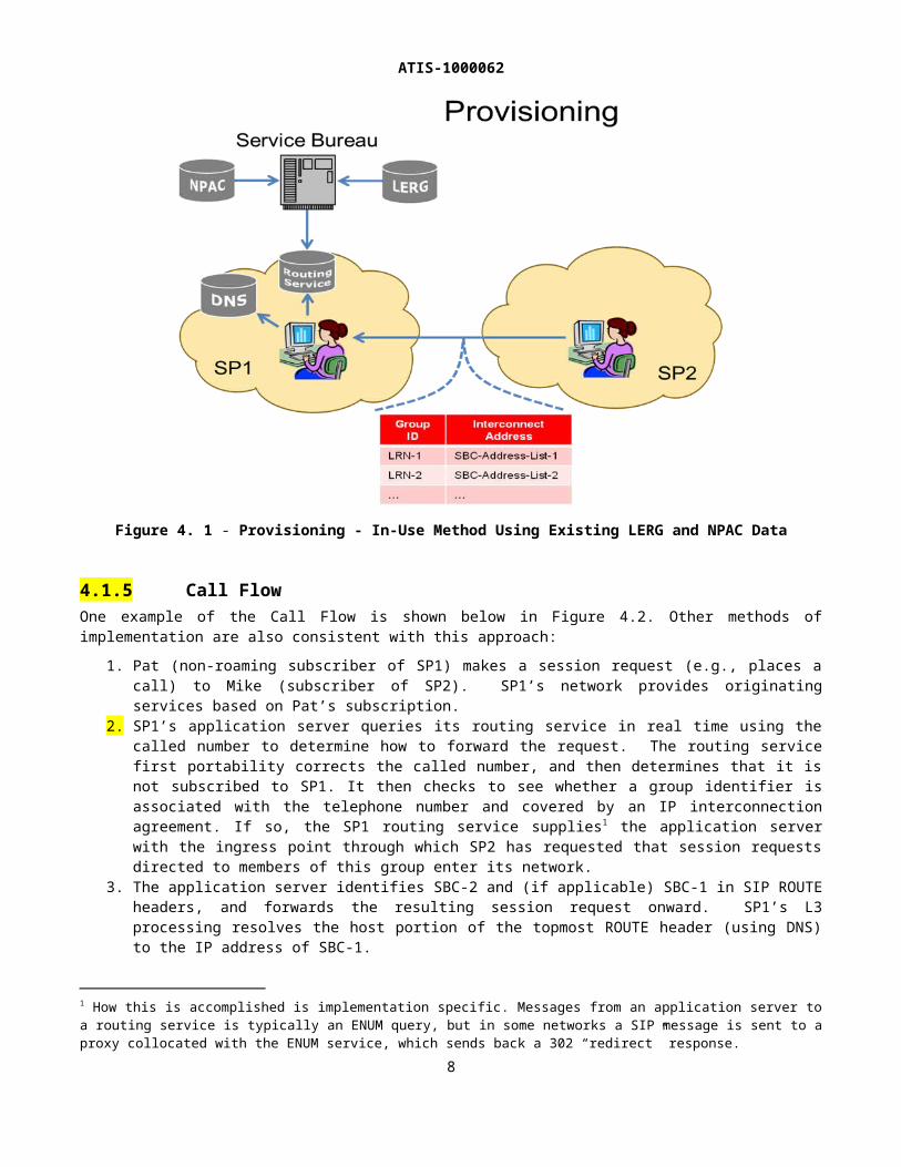
4.1.4 ProvisioningA Provisioning diagram is shown below in Figure 4.1:
In this provisioning example, SP1 provisions its Routing Service and DNS based upon information provided by SP2. In this example, group identifiers (LRNs) are correlated with SBC interconnect IP addresses and domain names provided by SP2.
Figure 4. 1 - Provisioning - In-Use Method Using Existing LERG and NPAC Data
4.1.5 Call FlowOne example of the Call Flow is shown below in Figure 4.2. Other methods of implementation are also consistent with this approach:
1. Pat (non-roaming subscriber of SP1) makes a session request (e.g., places a call) to Mike (subscriber of SP2). SP1’s network provides originating services based on Pat’s subscription.
2. SP1’s application server queries its routing service in real time using the called number to determine how to forward the request. The routing service first portability corrects the called number, and then determines that it is not subscribed to SP1. It then checks to see whether a group identifier is associated with the telephone number and covered by an IP interconnection agreement. If so, the SP1 routing service supplies1 the application server with the ingress point through which SP2 has requested that session requests directed to members of this group enter its network.
3. The application server identifies SBC-2 and (if applicable) SBC-1 in SIP ROUTE headers, and forwards the resulting session request onward. SP1’s L3 processing resolves the host portion of the topmost ROUTE header (using DNS) to the IP address of SBC-1.
1 How this is accomplished is implementation specific. Messages from an application server to a routing service is typically an ENUM query, but in some networks a SIP message is sent to a proxy collocated with the ENUM service, which sends back a 302 “redirect” response.
6

ATIS-10000624. SBC-1 removes the topmost ROUTE header (which identifies itself) and forwards the session request
based on the next one (which identifies SBC-2). To do so it resolves (using DNS) the host portion of that header, yielding the IP address of SBC-2.
5. SBC-2 removes the topmost ROUTE header (which identifies itself) and admits the message to SP2’s network, forwarding it to an application server, and eventually to Mike. How SP2 performs these functions is SP specific.
Figure 4. 2 - Call Flow -In-Use Method Using Existing LERG and NPAC Data
4.2 In-Use Method with LERG EnhancementsThis section describes the exchange of data for IP routing and interconnection using existing industry database systems, architectures and processes, with LERG enhancements as needed for routing of E.164 Addressed Communications over IP Network-to-Network Interconnection (NNI).
This approach would allow existing downstream systems and processes to be utilized and enhanced, as may be needed, with minimal impact to service providers. The LERG and NPAC have evolved since their inception to support new technologies and industry processes. These systems have embedded governance processes that allow the industry to facilitate system process enhancements as required by service providers. Consequently, a solution to utilize existing database systems would allow the industry to continue to manage process evolution as it pertains to IP routing and interconnection within established industry forums that are proven, efficient, cost effective, and are balanced across industry segments.
Utilizing LERG for support of IP interconnection could maintain consistency of data exchange across the multi-carrier ecosystem. Additionally, utilization of the LERG routing data allows the originating provider to retain control of egress route selection through management of its own translations and routing tables.
Service providers can continue to leverage NPAC and existing Local Number Portability (LNP) system processes, such as Service Order Administration (SOA) and the LSMS framework, with minimal impact to their business processes for ported and pooled numbers that are serviced by IP technology.
The existing industry framework supports the evolution of TDM to IP routing and interconnection, however, existing database systems would need to be enhanced according to the industry requirements. The following items require further study and are possible areas of enhancement to these industry databases in support of IP routing for both PSTN transition and all IP networks. Upon industry consensus, BIRRDS/LERG can be enhanced to support:
service provider exchange of Uniform Resource Identifier (URI) to identify I-SBCs (session border controllers) or other IP interconnect equipment.
7
ATIS-1000062 service provider exchange of location data for I-SBCs or other IP interconnect equipment. For example,
Session Border Controller Location Entities could still be specified per ATIS-0300253, Identification of Location Entities for the North American Telecommunications and exchanged between service providers.
a process for service providers to exchange service types and attribute parameters (e.g., Classes of Service, CODEC capabilities, Transcode Free Operation (TrFO), facsimile support, etc.) that are associated with a specific Session Border Controller (SBC)/IP interconnection point. This can be similar to the current process in BIRRDS/LERG to identify TDM switch attributes known as Switch Office Functionality indicators (SOFs).
a process for flagging specific LRNs, as defined by the service provider, to be “related to” IP interconnection.
a process to support service provider exchange of per service type (e.g., SIP, PSTN, mailto, etc.) Uniform Resource Identifier (URI) and parameter exchange.
a process to exchange potential PSTN and IP routes simultaneously. a process to retain policy control for selection of primary and alternate egress routes and all the
associated business processes. a process to validate Domain Names and potentially full URIs associated with an IP interconnection point
prior to accepting such routing information for exchange. a process to have routing/interconnection database systems support alternative number conservation
methods (e.g., use of 100 or other number block sizes); BIRRDS/LERG can be enhanced to meet this need, all while maintaining compatibility with routing on existing NPA/NXX and thousands blocks assignments. Support for a “Just In Time” number allocation model at a single TN level warrants further evaluation; however, in that case an industry requirement for coexistence with block level assignments should also be evaluated.
more frequent routing data exchanges than daily, then BIRRDS/LERG can be enhanced to meet this need.
8

ATIS-1000062
4.2.1 Call Flow
Figure 4. 3 - Call Flow – In-Use Method using LERG Enhancements
Session 1 – IP Session via PSTN Interconnection(1) A session is originated and sent to the Call Session Control Function (CSCF).
(2&3) The CSCF performs an internal query to its routing server to retrieve routing data for the called number.
(4) If the CSCF determines that the called number requires interconnection via the PSTN to Terminating Service Provider 1, then the session is routed to the appropriate trunk gateway where it is converted to TDM.
(5) The session is routed internally to the trunk gateway and point of interconnection for Terminating Service Provider 1. The call is converted back to IP within the terminating service provider network.
(6&7) Terminating Service Provider 1 then signals the terminating CSCF to complete the call. Terminating Service Provider 1 may be an IP network but the means of interconnection is still via the PSTN. It is probable, per the illustration, that the terminating service provider offers both media gateways and I-SBCs to accept sessions during the IP transition phase.
Session 2 – IP Session via IP-IP Interconnection(1) A session is originated and sent to the Call Session Control Function (CSCF).
(2) The CSCF performs an internal query to its routing server to retrieve routing data for the called number.
(3) The routing server returns a URI and the CSCF determines that the called number can accommodate an IP-NNI to the Terminating Service Provider,
(3a) The CSCF will then query its local DNS to resolve the URI to the IP address of the I-SBC of the terminating network.
(8) A SIP invite is sent to the egress I-SBC of the originating network that has connectivity to the ingress I-SBC of the terminating service provider.
9

ATIS-1000062(9) A SIP Invite is forwarded to the terminating service providers ingress I-SBC. Route selection is based on IP peering agreement between SPs as well as service attributes, least cost routing, etc.
(10&11) Terminating Service Provider 2 signals to the appropriate CSCF and the end-to-end session is established.
10

ATIS-1000062
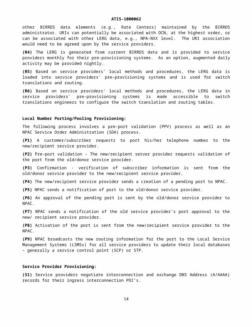
4.2.2 Provisioning
Figure 4. 4 - Provisioning – In-Use Method using LERG Enhancements
Routing Data Provisioning:(R1) Service provider develops a switch/point-of-interface (POI) CLLI Code and associated location attributes in the CLONES database.
(R2a) The CLONES database provides newly developed CLLI Code and location reference data to BIRRDS. The location reference information is used by service providers in support of developing new BIRRDS switch/POI records.
(R2b) The National Exchange Carrier Association (NECA), provides new Company Codes (a subset of Operating Company Numbers (OCNs)), as they are assigned, to BIRRDS.
(R2c) National CO Code (NXX) Administrators and the Thousands-Block Pooling Administrator (US only) establish base CO Code and block assignment records in BIRRDS.
(R3) Service provider updates BIRRDS with switch/POI information (e.g., actual switch, points of interface, trunk gateways, call agents, Signaling Transfer Points (STPs), etc.), homing arrangements, Location Routing Numbers (LRNs), and detailed information supporting the CO Code NPA/NXX, NPA/NXX-X. This data is integrated with other BIRRDS data elements (e.g., Rate Centers) maintained by the BIRRDS administrator. URIs can potentially be associated with OCN, at the highest order, or can be associated with other LERG data, e.g., NPA-NXX level. The URI association would need to be agreed upon by the service providers.
(R4) The LERG is generated from current BIRRDS data and is provided to service providers monthly for their pre-provisioning systems. As an option, augmented daily activity may be provided nightly.
11

ATIS-1000062(R5) Based on service providers’ local methods and procedures, the LERG data is loaded into service providers’ pre-provisioning systems and is used for switch translations and routing.
(R6) Based on service providers’ local methods and procedures, the LERG data in service providers’ pre-provisioning systems is made accessible to switch translations engineers to configure the switch translation and routing tables.
Local Number Porting/Pooling Provisioning: The following process involves a pre-port validation (PPV) process as well as an NPAC Service Order Administration (SOA) process.
(P1) A customer/subscriber requests to port his/her telephone number to the new/recipient service provider.
(P2) Pre-port validation - The new/recipient server provider requests validation of the port from the old/donor service provider.
(P3) Confirmation - verification of subscriber information is sent from the old/donor service provider to the new/recipient service provider.
(P4) The new/recipient service provider sends a creation of a pending port to NPAC.
(P5) NPAC sends a notification of port to the old/donor service provider.
(P6) An approval of the pending port is sent by the old/donor service provider to NPAC.
(P7) NPAC sends a notification of the old service provider’s port approval to the new/ recipient service provider.
(P8) Activation of the port is sent from the new/recipient service provider to the NPAC.
(P9) NPAC broadcasts the new routing information for the port to the Local Service Management Systems (LSMSs) for all service providers to update their local databases – generally a service control point (SCP) or STP.
Service Provider Provisioning:(S1) Service providers negotiate interconnection and exchange DNS Address (A/AAAA) records for their ingress interconnection POI’s.
(S1A) Each service provider provisions the records received from the other service provider in its internal DNS. These IP addresses correspond to the destination service provider’s I-SBCs that constitute the application layer POIs.
4.2.3 SummaryAs industry requirements develop, and if they direct a solution to utilize existing database systems to support IP routing and interconnection information exchange, the capabilities of BIRRDS/LERG and NPAC database systems and their existing processes can be leveraged and enhanced to meet this need. There are several advantages for utilizing the existing database systems and infrastructure to support IP routing and interconnection. In particular, and at a minimum, this approach:
Retains egress routing policy at the originating provider and allows QoS, least cost routing and other operational and commercial considerations to continue to play a role in determining primary and alternate routes for interconnection.
Provides simultaneous PSTN and IP routes in an efficient manner should both options be available for a particular session including resiliency during the transition phase should one method be unavailable at a given moment.
Leverages existing vehicles and processes for industry-wide routing information exchange of new IP parameters, URIs, and locations on a per service type basis.
Avoids additional carrier overhead and costs that would result from adding network gear (hardware, software, and associated engineering, provisioning, monitoring, and security processes) for external
12

ATIS-1000062queries (e.g., ENUM) in per call/session setup. Likewise it avoids additional points of network failure and potential performance degradation.
Can coexist with an ENUM approach to routing data exchange should that be adopted between two service providers who agree to do so.
Retains and leverages existing process management for the evolution of IP information exchange and is governed by established neutral industry forums and based on specific requirements developed by the industry.
BIRRDS/LERG and NPAC database systems and processes have efficiently evolved to support new network routing and interconnection data exchange for the past many years. These systems are likewise deeply imbedded into service provider operations and business processes for billing, reporting, network engineering, least cost routing, and service activation, among others. Such factors are equally as important to service providers as deploying IP interconnection technology itself. Utilizing existing industry database systems and processes for IP routing data exchange would minimize potentially broad impacts to service providers and will support a more cost effective, reliable, seamless, and accelerated transition from TDM to an all IP environment.
In addition, enhancements allowing SPs the option to mechanize the distribution of their list of IP group identifiers including OCNs, LRN, and NXXs using existing BIRRDS/LERG distribution capabilities is under consideration by the Common Interest Group on Routing and Rating (CIGRR).
4.3 Enhancing LERG to Provide a Tier 1 ENUM RegistryThis section describes how the LERG can be enhanced to support Tier 1 ENUM Registry information exchange for routing of E.164 Addressed Communications over IP Network-to-Network Interconnection (NNI). To accommodate this capability the existing LERG would need to be enhanced to include Tier 2 Name Server information.
The LERG was initially designed for routing of interLATA Time Division Multiplex (TDM) calls by interexchange carriers but has effectively evolved since its inception to support new networks and technologies. It continues to evolve with governance processes that allow the industry to facilitate system process enhancements as required by service providers. For example, the LERG has also evolved to provide support for information exchange between all types of service providers including Incumbent Local Exchange Carriers, Competitive Local Exchange Carriers, Wireless Service Providers, and Voice over IP (VoIP) Providers, etc. In addition, the LERG evolved to support the exchange of hybrid TDM/IP routing and interconnection architectures, Call Agent/Media Gateway homing arrangements and NPA/NXX assignments, to name a few.
Consequently, a solution to utilize LERG to provision Tier 2 Name Server information as well as any other IP data elements would allow the industry to continue to effectively manage process evolution as it pertains to IP routing and interconnection. This management would reside within interactive industry processes that have proven efficient, cost effective, and balanced in regards to all industry segments.
The LERG, functioning as a Tier 1 Registry, would also maintain consistency of data exchange across the multi-service provider ecosystem as opposed to a third party’s tiered solution that might be difficult to maintain a consistent quality of service benchmark across service providers.
4.3.1 Call FlowA high level reference architecture is provided below that illustrates how the ENUM Domain Name System (DNS) query sequence would function during a session. In this example a Session Initiation Protocol (SIP) session is depicted.
13
ATIS-1000062
Figure 4. 5 - Call Flow – Enhancing LERG to Provide Tier 1 ENUM Registry
1. A session is initiated2. The Call Session Control Function (CSCF) initiates a query to the Routing Server for a routing lookup
(potentially using ENUM) in its local database3. The local database returns an NS record with the host name of a Delegated Tier 2 Name Server where
specific VoIP routing information can be found. The number may need to be port corrected to get the authorized service provider of record. The NS record for that provider was pre-provisioned by the LERG download.
4. The originating Service Provider resolves the FQDN in the NS record to the IP address of the terminating service provider’s Tier 2 ENUM server
5. The Routing Server sends an ENUM query to the terminating network’s Tier 2 Name Server6. The terminating network’s Tier 2 Name Servicer returns interconnect information in the form of one or
more Naming Authority Pointer (NAPTR) records within the ENUM response.7. The originating Service Provider resolves a NAPTR to a SIP URI and thhen the hostname in the SIP URI
to obtain the IP address of an agreed upon terminating Service Provider’s ingress SBC8. Based in the information received, the originating network initiates a SIP invite to the terminating network
to initiate a SIP session
By implementing an ENUM approach, the network infrastructure needs to be enhanced to accommodate the additional queries as depicted in sequences 5-6.
Additionally, the network needs to standardize the information, content, and format in the Uniform Resource Identifier (URI). This includes standardizing the service parameters that are going to be supported for when the originating service provider receives the NAPTR records there is an agreed to and standardized process for how to use them for egress routing and session set up.
It should be pointed out that the initiation of a SIP session, sequence 8 above, has additional cross-network messages that are not depicted in this reference architecture but need to be supported by all service providers. From an originating service provider perspective, there are at least 1 additional ENUM query messages to accompany the 3 or 4 SIP set up messages, meaning the originating CSCF, and likely their I-SBC, must process more messaging in an ENUM architecture.
4.3.2 Provisioning FlowA high level reference architectures is proposed below that illustrates the provisioning sequence that could be implemented.
14
ATIS-1000062
Figure 4. 6 - Provisioning - Enhancing LERG to Provide Tier 1 ENUM Registry
As depicted in Figure 4.6, service providers would obtain the Tier 2 Name Server information from the LERG to enable a functional IP Network to Network Interconnection. This figure illustrates a logical view that may be realized by different operations systems.
Steps R1 and R2 provision Public Switched Telephone Network (PSTN) information while R3 through R6 includes both new IP information (i.e., the Name Server info) and existing PSTN data. Essentially, the current provisioning and routing data exchange systems and methodology for the PSTN can be applied directly to service provider Name Server data exchange. Also note that the number port provisioning flow is unchanged from today’s methodology.
Routing Data Provisioning:(R1) Service provider develops a switch/point-of-interface (POI) CLLI Code and associated location attributes in the Common Language® CLONES database.
(R2a) The CLONES database provides newly developed CLLI Code and location reference data to the Business Integrated Routing and Rating Database System (BIRRDS). The location reference information is used by service providers in support of developing new BIRRDS switch/POI records.
(R2b) The National Exchange Carrier Association (NECA), provides new Company Codes (a subset of Operating Company Numbers (OCNs)), as they are assigned, to BIRRDS.
15

ATIS-1000062(R2c) National CO Code (NXX) Administrators and the Thousands-Block Pooling Administrator (US only) establish base CO Code and block assignment records in BIRRDS.
(R3) Service provider updates BIRRDS with Tier 2 Name Server information, switch/POI information (e.g., actual switch, points of interface, trunk gateways, call agents, signaling transfer points (STPs), etc.), homing arrangements, Location Routing Numbers (LRNs), and detailed information supporting the CO Code NPA/NXX and Thousands-Blocks that they have been assigned. This data is integrated with other BIRRDS data elements (e.g., Rate Centers) maintained by the BIRRDS administrator. At this time, BIRRDS can perform domain validations to validate Tier 2 Name Server accuracy. Name Server records can potentially be associated with OCN, at the highest order, or can be associated with other LERG data, e.g., CO level. That Name Server association would need to be agreed upon by the service providers.
(R4) The LERG is generated from current BIRRDS data and is provided to service providers monthly for their pre-provisioning systems. As an option, augmented daily activity may be provided nightly.
(R5) Based on service providers’ local methods and procedures, the LERG data is loaded into service providers’ pre-provisioning systems and is used for both PSTN and IP interconnection and routing covering switch translations and routing.
(R6) Based on service providers’ local methods and procedures, the LERG data in service providers’ pre-provisioning systems is made accessible to switch translations engineers to configure the switch translation, routing tables and data elements used for both PSTN and IP interconnection and routing, e.g., Tier 2 Name Server information for IP.
Local Number Porting/Pooling Provisioning:The following process involves a pre-port validation (PPV) process as well as a Number Pooling Administration Center (NPAC) Service Order Administration (SOA) process
(P1) A customer/subscriber requests to port his/her telephone number to the new/recipient service provider.
(P2) Pre-port validation - The new/recipient server provider requests validation of the port from the old/donor service provider.
(P3) Confirmation - verification of subscriber information is sent from the old/donor service provider to the new/recipient service provider.
(P4) The new/recipient service provider sends a creation of a pending port to NPAC.
(P5) NPAC sends a notification of port to the old/donor service provider.
(P6) An approval of the pending port is sent by the old/donor service provider to NPAC.
(P7) NPAC sends a notification of the old service provider’s port approval to the new/ recipient service provider.
(P8) Activation of the port is sent from the new/recipient service provider to the NPAC.
(P9) NPAC broadcasts the new routing information for the port to the Local Service Management Systems (LSMSs) for all service providers to update their local databases likely a Routing Server.
Service Provider Provisioning:Service providers negotiate interconnection and exchange and provide Address records for their Tier 2 name servers (S1). In addition, address (A/AAAA) records for the hostname FQDNs in URIs derived from the NAPTR records that will be provided in the responses from their Tier 2 name servers. These IP addresses correspond to the destination service provider’s I-SBCs that constitute the application layer POIs. Each service provider provisions the records received from the other service provider in its internal DNS (S1A).
In this reference architecture, BIRRDS/LERG would need to be modified/enhanced to allow the administrators to provide the registration of the Tier 2 name server information.
16

ATIS-1000062
4.3.3 SummaryA solution that utilizes the LERG as the thin Tier 1 Registry would allow the industry to continue to leverage existing processes for data exchange of the ENUM Name Server records with caching in local databases to avoid external NS queries.
The existing industry framework supports the exchange of TDM and IP routing and interconnection, however, existing database systems would need to be enhanced according to the industry requirements in order to exchange Tier 2 NS records and other IP routing information. The following items are possible areas of enhancement to LERG functioning as the Tier 1 Registry for IP routing and interconnection:
Adopt an ENUM architecture but avoid the overhead and complexity of external NS queries by supporting service provider exchange (i.e., local downloads) of Tier 2 Name Server information.
Assign and exchange a single Name Server record for a given service provider (e.g., an OCN) or a set of Name Server Records depending on the NPA/NXX or other considerations (such as East vs. West). It is worth discussing what granularity a Name Server will need to support including what requirement would drive Name Servers at a full 10 digit TN level.
Validate Domain Names and potentially full URIs associated with a Name Server address prior to accepting such routing information for exchange.
Support more frequent routing data exchanges than daily. Global access to the NS information requires further evaluation.
5 Per-TN Overview & ApproachesA number of service providers have identified that they have a need for more molecular routing than that based on NANP aggregation elements as discussed in the previous section.
In general these needs arise where TNs may share common point of interconnection (PoI) for TDM interconnection (and are thus associated with the same LRN or CLLI) but need to be treated differently for IP interconnection.
For example, wireless SPs are migrating their existing 2G/3G subscribers to VoLTE – from TDM to IP based user equipment (UE). For VoLTE to VoLTE calls, IP interconnection makes sense for a number of reasons – support for high definition (HD) voice and other Rich Communication Services (RCS) features and elimination of needless IP-TDM and TDM-IP conversions as would be required for TDM interconnection. SPs must still offer TDM interconnection for VoLTE TNs since not all SPs are capable or willing to provide IP interconnection. And because the migration will be gated by customer adoption of VoLTE capable UE, SPs may want to maintain existing TDM PoIs for both 2G/3G and VoLTE TNs and maintain existing TDM routing to those PoIs. Moreover, it may be desirable not to use the IP interconnection serving VoLTE TNs for 2G/3G TNs. First, additional network equipment must be deployed sooner than if IP interconnection scales with VoLTE adoption and, second, 2G/3G calls will be forced to go through unnecessary TDM/IP and IP/TDM conversions. These issues can be avoided if an SP can specify IP interconnection routing for VoLTE TNs separately from the associated LRNs.
A related case cited during IP-NNI Task Force discussions occurs in the deployment of RCSe capabilities outside North America in situations where voice calls and sessions using other RCS features need to be routed differently. This may be particularly the case where number portability methods may not support aggregation via methods like porting to different LRNs.
There may be other use cases for TN routing as well. It has been suggested that per-TN routing could be used to either avoid routing calls to fax numbers over IP interconnections using incompatible compression or taking other measures to insure adequate transmission quality.
The remainder of this section discusses different approaches to providing per-TN routing information. The first three make use of an authoritative industry registry for the exchange of per-TN data while the fourth and fifth discusses the exchange of per-TN information on a bilateral basis or via ad hoc service bureaus without the use of shared industry infrastructure. Of the registry-based solutions, the first uses the registry to provide routing data (SIP URIs) directly while the other two are based on a tiered ENUM approach in which the registry provides name server (NS) records that direct the interconnect partner how to query the terminating service provider for specific
17

ATIS-1000062routing data (NAPTR records resolving to SIP URIs). Two of the registry solutions use the NPAC to perform the registry function while the other proposes an independent registry.
5.1 NPAC TN RegistryThis approach makes use of the existing Voice URI field in the NPAC subscription version, essentially as originally contemplated. This field provides a SIP URI that, in conjunction with bilaterally exchanged IP connection information as in the aggregate approaches discussed in section 4, resolves to the traffic exchange route(s) agreed to between the interconnection partners.
Service providers wishing to provide per-TN routing perform the following provisioning activities:
1. As part of bilateral traffic exchange negotiations provide mappings for SIP URI hostnames to SBC IP addresses.
2. Populate the Voice URI field in the NPAC subscription version for TNs available for IP interconnection with the appropriate SIP URI. The URI will be a full SIP URI (e.g., sip:[email protected];user=phone ) but without the tel URI number portability parameters as defined in RFC 4694..
NPAC provisioning is carried out through Change Orders 429 and 442, compliant SOAs. If a TN is not pooled or ported, the pseudo LRN capability is used to create a subscription version.
Service providers electing to use the per-TN routing information provided by their interconnect partner will:
1. Provision the hostname – IP address mappings into their internal DNS (A/ AAAA records). 2. Provision TN-URI mappings from the NPAC into their internal routing servers using Change Orders 429,
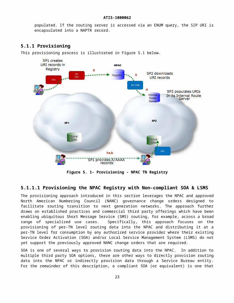
and 442 compliant LSMS to obtain the NPAC data. If the routing server is accessed via a SIP query, the SIP URI may be directly populated. If the routing server is accessed via an ENUM query, the SIP URI is encapsulated into a NAPTR record.
5.1.1 ProvisioningThis provisioning process is illustrated in Figure 5.1 below.
18

ATIS-1000062
Figure 5. 1- Provisioning - NPAC TN Registry
5.1.1.1 Provisioning the NPAC Registry with Non-compliant SOA & LSMS The provisioning approach introduced in this section leverages the NPAC and approved North American Numbering Council (NANC) governance change orders designed to facilitate routing transition to next generation networks. The approach further draws on established practices and commercial third party offerings which have been enabling ubiquitous Short Message Service (SMS) routing, for example, across a broad range of specialized use cases. Specifically, this approach focuses on the provisioning of per-TN level routing data into the NPAC and distributing it at a per-TN level for consumption by any authorized service provider where their existing Service Order Activation (SOA) and/or Local Service Management System (LSMS) do not yet support the previously approved NANC change orders that are required.
SOA is one of several ways to provision routing data into the NPAC. In addition to multiple third party SOA options, there are other ways to directly provision routing data into the NPAC or indirectly provision data through a Service Bureau entity. For the remainder of this description, a compliant SOA (or equivalent) is one that supports the following two previously approved NANC change orders: NANC 429, “Uniform Resource Identifier (URI) Field for Voice” and NANC 442, “Pseudo Location Routing Number (LRN)”.
LSMS is used to receive information from the NPAC and is the service provider’s database containing all information required for correct call routing when a customer changes from one service provider to another. In addition to multiple third party LSMS options, there are other ways to directly receive routing data from the NPAC or indirectly receive data through a Service Bureau entity. For the remainder of this description, a compliant LSMS (or equivalent) is one that supports NANC 429 and NANC 442.
It should be noted that NANC 372, “SOA/LSMS Interface Protocol Alternatives”, supports the addition of an XML-based interface along with the existing, but generally more complex CMIP-based interface. Implementations of NANC 372 could be one way for existing SOA/LSMS to address full industry compliance with NANC 429 and NANC 442. However, this is not assumed in the remainder of this description.
The following description does assume that certain one-time activities previously discussed have already taken place between service providers (e.g., IP connectivity established). It should further be noted that this provisioning approach can support the NPAC in the role of either a Tier 1 (i.e., routing data in a format that
19
ATIS-1000062identifies service provider Tier 2 servers – see also Section 5.2) or Tier 2 (i.e., routing data in a format that identifies an interconnect SBC, or I-SBC, domain, where the specific “trunk group” or “route” is ultimately designed through a bi-lateral service provider information exchange – this Section 5.1). The remainder of this description assumes a Tier 2 role, where the routing data to be exchanged in the NPAC is in the form of a SIP URI like “sip:<telephone number>@sbc1.sp1.com”. However, the approach doesn’t rely on just this specific URI format.
Generally, the NPAC Location Routing Number (LRN) for ported telephone numbers or NANP NPA-NXX for native telephone numbers is used to route calls between service providers. Similarly, the NPAC Service Provider IDentification (SPID) or NANP Operating Company Number (OCN) is typically used to route text messages between service providers. Over the past five years or so, multiple commercial wireless use cases have arose where the SPID or OCN associated with a particular telephone number in these recognized authoritative databases (after port-correction) was not sufficient for routing within the ecosystem. Further, these authoritative databases, at the time, were limited in their support of such use cases. Consequently, several commercial third party services were introduced to support these use cases while they work hand-in-hand with the recognized authoritative databases.
The key constraint in the NPAC has since been removed through NANC 442 that allows native telephone numbers and associated information to be stored in the NPAC. The PSTN to IP transition use case and others being discussed are analogous to those that have naturally evolved around text messaging where additional information beyond an NPAC LRN or NANP NPA-NXX is required in support of routing. The provisioning flow summarized below uses the NPAC in support of the use case(s) minimally discussed within this ATIS SIP Forum IP- NNI Task Force. Specifically, it proposes to use the industry-approved VOICE URI field (NANC 429) that is one field of many in the existing, standard NPAC database record. Further, it leverages at least one established commercial third party service to provision and distribute NPAC database records with URI field data.
Figure 5.2 below highlights the provisioning and distribution aspects of the approach. The routing data input is assumed to be in the form of an NPA-NXX-XXXX. Further, SP1 has both a compliant SOA and LSMS while SP2 does not.
Figure 5. 2 - Provisioning NPAC as a TN Registry for Non-compliant SOA and LSMS
20

ATIS-1000062
1. SP1 and SP2 negotiate bilateral IP interconnection and exchange. In support of routing data exchange, each provides an agreed to mapping of IP address records (A/AAAA records) to FQDNs (or URI domains) corresponding to their respective I-SBCs. Each SP then provisions these records into their respective local DNS. An example of such a mapping for one URI domain could be:
URI Domain IP Address
sbc1.sp1.com 138.34.23.3
sbc1.sp1.com 182.36.12.1
sbc1.sp1.com 58.23.12.90
2. SP1 populates the NPAC VOICE URI field in the associated subscription version (SV) record through its SOA (or equivalent) as new numbers are provisioned or existing numbers become available for IP interconnection. Again, the routing data to be exchanged is assumed, for this description, to be in the form of a SIP URI like “sip:<telephone number>@sbc1.sp1.com”.
3. SP1 downloads per-TN VOICE URI field data from SP2 (along with other existing NPAC data for number portability) through its LSMS (or equivalent).
4. SP1 extracts per-TN VOICE URI field data from SP2 (along with other existing NPAC data for number portability) and provisions it into their internal route server. Note that the details of how this routing data gets represented and used are specific to SP1.
5. SP2 shares per-TN VOICE URI routing data with an established third party service. For example,a. SP2 designates existing TN 508-332-2319 for IP interconnection.b. The associated ingress SBC domain is “sbc1.sp2.com”.c. SP2 establishes a Letter of Authorization (LOA) with the third party supporting this approach (if such
an LOA doesn’t already exist).d. The TN/ingress SBC domain/Action is then shared with the third party service over one of several
published APIs (e.g., a flat file with a row “5083322319,sbc1.sp2.com,A” where “A”=Add).6. The third party service for SP2 manages as per-TN VOICE URI field data in the NPAC on behalf of SP2.
For one example use case, a. Third party service interprets row “5083322319,sbc1.sp2.com,A” in a shared flat file and generates
the associated NPAC provisioning actions. For example,i. Modify action is generated to add sip:[email protected] to the VOICE URI field for
this existing SV record in the NPAC7. At a configured interval (e.g., every 15 minutes), the third party service checks for changes in SP1 VOICE
URI field data and distributes them over a pre-configured SP2 interface separate from the non-compliant LSMS interface which continues to receive existing NPAC data for number portability.
8. SP2 extracts per-TN VOICE URI field data from SP1 (along with other existing NPAC data for number portability) and provisions it into their internal route server. Note that the details of how this routing data gets represented and used are specific to SP2.
This sub-section expands on sections 5.1.1 (above) and 5.2.1 (to be discussed in the next section) where the NPAC is proposed for supporting per-TN routing. Specifically, it focuses on an approach for supporting the provisioning of per-TN level routing data into the NPAC and distributing it at a per-TN level for consumption by any authorized service provider where their existing SOA and/or LSMS may not yet be compliant with the previously approved NANC change orders that are required. The provisioning approach is transparent to service providers who have compliant SOA and LSMS. For service providers who do not, their per-TN level routing data can be shared through an established third party and provisioned (on their behalf) into the NPAC. This per-TN routing data can then be directly consumed by any participating service provider with a compliant LSMS or distributed through an established third party over a pre-configured interface.
21

ATIS-1000062
5.1.2 Call FlowOn call origination, the originating service provider will query their routing server and obtain the corresponding SIP URI for numbers available for IP interconnect. They will resolve the hostname from the URI in their internal DNS to obtain the IP address of the terminating provider’s ingress SBC.2 The call flow is shown in Figure 5.3 below:
Figure 5. 3 - Call Flow - NPAC TN Registry
1. SP2 Caller dials destination number2. SP2 S-CSCF queries internal route server and SP2 route server responds with a URI passed back to S-
CSCF3. SP2 S-CSCF resolves the hostname in the SIP URI to obtain the IP address of an agreed upon SP1
ingress SBC4. A SIP INVITE is sent to egress SBC of SP2 that has layer 3 connectivity to the ingress SBC of SP15. The SIP INVITE is forwarded to the SP1 ingress SBC.6. and 7. SP1 terminates the call to its end user.
Note that although the NPAC URI approach is proposed primarily in support of per-TN information exchange, the Voice URI can also be populated on thousands block level, thus providing some level of aggregation where appropriate.
5.2 The NPAC as a Tier 1 ENUM Registry Consistent with 3GPP IMS recommendations for inter-carrier routing, an ENUM-based architecture is proposed for routing across the IP NNI. The essence of this architecture is a query using the protocol described in RFC 6116. 3GPP recommendations do not specify, however, the details of the ENUM data repository to be queried nor the source of the data in that repository. This proposal includes recommendations for these matters, the corresponding data formats, and the manner in which the results of ENUM queries are processed to resolve
2 There may be alternate approaches to combining the bilaterally exchanged URI-IP address mappings and the TN-URI mappings obtained from the Registry and combining them in a routing server for session establishment.
22
ATIS-1000062responses to the IP address(es) toward which a SIP INVITE to the destination network Session Border Controller are to be directed.
The classic ENUM “golden tree” architecture assumed a tiered structure in which a Tier 0 registry (such as the one currently managed by RIPE for the e164.arpa user ENUM domain) contains name server (NS) records pointing to the Tier 1 name servers authoritative for individual E.164 country codes. The Tier 1 registries in turn consist of NS records pointing to the authoritative Tier 2 server for a specific E.164 number. The Tier 2 servers, maintained by or for the assignee of the number, contained NAPTR records that resolved to the URIs needed to establish communication to the number in question.
As the industry has yet to establish a universally recognized Tier 0 for infrastructure ENUM (RFC 5067) as opposed to user ENUM, a combined Tier 0/1 registry is proposed for the US portion of Country Code 1. 3 This Tier 0/1 registry is in principle extensible to other portions of Country Code 1 if desired by the competent authorities and may eventually be linked to registries for other country codes or to a global Tier 0 when and if consensus on such a Tier 0 emerges. In the interim the registry simply contains NS records for individual numbers in the US portion of CC1.
To speed deployment and leverage existing infrastructure it is proposed that the Number Portability Administration Center (NPAC), the local number portability database of record, serve as the Tier 0/1 registry. Unlike the Tier 0 and Tier 1 registries in the classic ENUM architecture, the NPAC is not a DNS name server and is not queried during call processing. It can however download data for NS records to service providers or service bureaus for them to provision in their name servers to be queried on call origination.
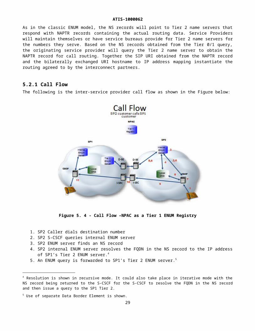
As in the classic ENUM model, the NS records will point to Tier 2 name servers that respond with NAPTR records containing the actual routing data. Service Providers will maintain themselves or have service bureaus provide for Tier 2 name servers for the numbers they serve. Based on the NS records obtained from the Tier 0/1 query, the originating service provider will query the Tier 2 name server to obtain the NAPTR record for call routing. Together the SIP URI obtained from the NAPTR record and the bilaterally exchanged URI hostname to IP address mapping instantiate the routing agreed to by the interconnect partners.
5.2.1 Call FlowThe following is the inter-service provider call flow as shown in the Figure below:
3 In infrastructure ENUM, the Tier 1 servers point to Tier 2 servers maintained by or for the service provider of record for the number.
23

ATIS-1000062
Figure 5. 4 - Call Flow –NPAC as a Tier 1 ENUM Registry
1. SP2 Caller dials destination number2. SP2 S-CSCF queries internal ENUM server3. SP2 ENUM server finds an NS record 4. SP2 internal ENUM server resolves the FQDN in the NS record to the IP address of SP1’s Tier 2 ENUM
server.4
5. An ENUM query is forwarded to SP1’s Tier 2 ENUM server.5
6. SP1’s Tier 2 ENUM server responds with a NAPTR record(s) passed back to S-CSCF7. SP2 S-CSCF processes the NAPTR record set returned resulting in a SIP URI8. SP2 S-CSCF resolves the hostname in the SIP URI to obtain the IP address of an agreed upon SP1
ingress SBC9. A SIP INVITE is sent to egress SBC of SP2 that has layer 3 connectivity to the ingress SBC of SP110. The SIP INVITE is forwarded to the SP1 ingress SBC.11. SP1 terminates the call to its end user.
5.2.2 ProvisioningProvisioning is shown in the Figure below:
4 Resolution is shown in recursive mode. It could also take place in iterative mode with the NS record being returned to the S-CSCF for the S-CSCF to resolve the FQDN in the NS record and then issue a query to the SP1 Tier 2.5 Use of separate Data Border Element is shown.
24

ATIS-1000062
Figure 5. 5 - Provisioning –NPAC as a Tier 1 ENUM Registry
1. Service providers negotiate interconnection and exchange, as part of the interconnect technical negotiation process,a. Address (A/AAAA) records for their Tier 2 name serversb. Address (A/AAAA) records for the hostname FQDNs in URIs derived from the NAPTR records that
will provided in the responses from their Tier 2 name servers. These IP addresses correspond to the destination service provider’s I-SBCs that constitute the application layer POIs.6
Each service provider provisions the records received from the other carrier in its internal DNS.
2. When new numbers are provisioned or existing numbers made available for IP interconnection by an SP, the SPa. Provisions NS record information for the number into the NPAC Voice URI field of the subscription
version (SV) of the number through its SOA. (If there is no existing subscription version one is added.)7
6 There are alternate approaches to the resolution of Tier 2 name servers and interconnection URI FQDNs. These include a)
exchange of SRV instead of A/AAAA records, b) resolution in the internet DNS, c) sharing through some controlled access industry system including but not necessarily limited to a private DNS.7 The VOICE URI field was originally defined to contain a URI that would be used to provide for IP routing of voice calls, but it is currently little used and has no explicit typing. It simply allows up to 255 characters.
It is proposed that NS record information be populated in the VOICEURI field in the form
tier2enum.serviceprovider.com
(i.e., just the nameserver name as an FQDN) as opposed to the full NS form:
3.8.0.0.6.9.2.3.6.4.1.e164enum.net IN NS tier2enum.serviceprovider.net
The full record form would be reconstituted by the service provider for provisioning in its ENUM server. Note that an NS record or records are generally provisioned for each individual number.
25

ATIS-1000062b. Provisions NAPTR records for number in its Tier 2 name server8.
c. Provisions internal NAPTR records in its internal ENUM server for use within network calls.3. Service providers download SVs from the NPAC, extract the NS information from the Voice URI field and
provision it as NS records into their internal ENUM server. Note that a record is provisioned for each TN.
Please note that the provisioning approach previously described in Section 5.1.1.1 can also support the proposed solution above where the NPAC is used as a Tier 1 ENUM Registry. Specifically, any authorized service provider whose SOA and/or LSMS does not support NANC Change Orders 429, and 442 can have their per-TN NS record information shared through an established third party and provisioned (on their behalf) into the NPAC. This per-TN NS record information can then be directly consumed by any participating service provider with a compliant LSMS or distributed through an established third party over a pre-configured interface.
5.2.3 SummaryA Tiered ENUM approach using the NPAC as the Tier 0/1 registry populates NS records into existing fields in the subscription version that already contains TDM routing elements. SVs are populated in the NPAC for each TN for which IP interconnection is offered. (If a TN is not otherwise ported or pooled an SV with a pseudo LRN is created). This approach simply enhances the existing interfaces (direct or via service bureaus) that all SPs have with the NPAC, requiring no new governance structures.
5.3 Independent ENUM RegistryThis section describes an independent ENUM Registry, for the exchange of data for IP routing and interconnection for routing of E.164 Addressed Communications over IP Network-to-Network Interconnection (NNI).
An ENUM Tier 1 Registry can enable authorized Service Providers to start directly exchanging routing information dynamically to enable session setup end-to-end over IP networks. Listed below are some requirement considerations and benefits of having a Registry:
The Tier 1 Registry could vastly reduce the NS record set by supporting policy-based NS provisioning. For example, an NS record value could be assigned to each Operating Company Number (OCN)/Service Provider ID (SPID) rather than to each telephone number, and/or NPA/NXX or Location Routing Number (LRN). This could also differ by TN and be at the discretion of the number holder.
The Tier 1 Registry needs to incorporate the existing NPAC Local Service Management System (LSMS) feed to provide Tier 2 NS records that are corrected for porting and pooled numbers when applicable.
Optimize session setup time; the Tier 1 ENUM query to the external registry could be avoided by using Zone Transfer protocol to download the NS records to local cache at each originating service provider. If this results in too many NS records for a simple Zone Transfer, then the NS data could be transferred in stages using a series of Zone Transfers.
Multiple NS records could be populated in the NPAC VOICEURI field through the use of some agreed upon separator character. This would allow for redundancy as it is expected that carriers would want to have multiple name server instances.
Note that an apex domain, for example, e164enum.net, needs to be agreed upon.8 The ENUM query may return multiple NAPTR records with different order, preference, and enumservice fields as defined in RFC 6116. Thus multiple options for interconnection can be provided including different gateways for different service types (e.g., voice versus video) where appropriate. A NAPTR for general SIP interconnection might look like
NAPTR 10 100 "u" "E2U+sip" "!^.*$!sip:\[email protected]; user=phone!" .
its resolution would result in the URI
sip:+14632963800@gw02. serviceprovider.net; user=phone
The querying service provider would then resolve the hostname
gw02.serviceprovider.net to obtain an IP address for the terminating provider’s ingress SBC.
26

ATIS-1000062 Support service providers who did not have the capability for locally caching the Tier 1 NS records, then
ENUM or another query protocol could be used by originating service providers to request the NS record from the Tier 1 Registry.
Optimize external queries whenever possible, then the Tier 0/1 Registry could optionally be used by service providers to capture and exchange NAPTR records instead of NS records thereby combining Tier 2 functionality in the Tier 1 Registry. This could be optional according to terminating service provider discretion and would be transparent to the originating service provider.
Allow for different NS records depending on the originating & terminating service provider combination, then the Tier 0/1 Registry could be configured with policy for source based resolution.. For example, some authorized Service Providers might input Name Server information for the same TN that in one case refers to the Tier 2 Name Server of a transit operator or IP eXchange (IPX) and in another case refers to their own terminating Tier 2 Name Server when they are peering or interconnecting directly with the originating service provider. While more powerful in the Tier 2 Name Server platform, this feature has potential application at the Tier 0/1 Registry level and could be used for either per session queries as well as to customize the data download to local cache.
Accommodate ENUM on a global basis, such as for incoming and outgoing international calls, then the Registry addresses for each country could be communicated to the global service provider community.
Support multiple Tier 0/1 Registries in order to avoid a sole supplier environment, then a mechanism, system processes and interfaces could be established to replicate data across participating registries. Technology exists to support such a requirement. Database peering has been formally endorsed by the FCC to support a competitive market of TV Whitespace geolocation databases.
Support source-based routing logic which can be used for services which require it.9
Support source-based routing logic which can use location to optimize physical transport path.9
5.3.1 Call FlowA session set-up is shown in Figure 5.6 that illustrates how the ENUM query sequence would function during a session. In this example a SIP session set up is depicted.
9 This could also be supported in other solutions that include an ENUM query to the terminating network.27

ATIS-1000062
Figure 5. 6 - Call Flow - Independent ENUM Registry
In Figure 5.6 a call is being initiated (1). The Call Session Control Function (CSCF) initiates a query to the Routing Server for a routing lookup (potentially using ENUM) in its local database (2). The local database returns an NS record with the host name of a Delegated Tier 2 Name Server where specific VoIP routing information can be found (3).
If not cached locally, the CSCF would initiate an ENUM DNS Query to the Tier 0/1 Registry (E1). The Tier 0/1 Registry returns an NS record (E2) for the service provider that holds the number. Steps (E1) and (E2) allow for the case where an originating service provider does not support receiving the Tier 0/1 Registry data in a local cache and must send a query to request the NS record at call setup.
The NS record indicates the host name of a Delegated Tier 2 Name Server where specific VoIP routing information can be found. The originating service provider resolves the FQDN in the NS record to the IP address of the terminating Service Provider’s Tier 2 ENUM server (4). This NS information is used by the originating network to send a query to the terminating network’s Tier 2 Name Server (5).
The terminating network’s Tier 2 Name Server returns specific routing information identifying the I-SBC in the form of one or more Naming Authority Pointer (NAPTR) records (6). The originating service provider resolves the domain name from the NAPTR URI to obtain the IP address of an agreed upon terminating network’s ingress I-SBC (7). Based on the information received, the originating network initiates a SIP invite (8) to the terminating network I-SBC in order to initiate a SIP session. .
By implementing an ENUM approach, the network infrastructure needs to be enhanced to accommodate the additional queries as depicted in sequences 2-6 as well as potentially E1 and E2. Additionally, the network needs to standardize the information, content, and format in the URI including what service parameters are going be supported so when the originating service provider receives the NAPTR records there is an agreed to and standardized process for how to use them for egress routing and session set up.
It should be pointed out that the initiation of a SIP session, sequence 8 above, has additional cross-network messages that are not depicted in this reference architecture but need to be supported by all service providers. A representative example of the message set, presuming the calling and called devices are SIP end-points, is shown in the Figure below.
28
ATIS-1000062
5.3.2 Provisioning FlowA high level provisioning reference architecture is shown in Figure 5.7 below to illustrate the high level process that would be required for service providers to configure the ENUM Tier 0/1 Registry to support routing data exchange.
Figure 5. 7 - Provisioning - Independent ENUM Registry
As depicted in Figure 5.7, the ENUM Tier 0/1 Registry can obtain data from all authorized Service Providers to enable routing data exchange for a functional IP Network to Network Interconnection service. One of the functions of the Registry is to allow authorized Service Providers to create, change, and/or modify ENUM domain name registrations in the Tier 0/1 Registry Database (1 and 1A).
Further it validates registrations via access to the authoritative LERG and Number Portability Administration Center (NPAC) data sources (2).
The NS records (Authoritative Name Server, DNS records), are sent via Zone Transfer protocol to local cache at all service providers (3). The local administration also provisions internal routing information into its own database (4). This includes providing the NS record resolution to an IP address. Service providers negotiate interconnection and exchange and provide Address (A/AAAA) records for their Tier 2 name servers (5). In addition, address records for the hostname FQDNs in URIs derived from the NAPTR records that will be provided in the responses from their Tier 2 name servers. These IP addresses correspond to the destination service provider’s I-SBCs that constitute the application layer POIs. Each service provider provisions the records received from the other service provider in its internal DNS (5A).
5.3.3 SummaryThis option proposes using a purpose-built ENUM solution as the data exchange mechanism for an IP routing industry framework. An ENUM Tier 1 Registry can enable authorized Service Providers to start directly exchanging routing information dynamically to enable session setup end-to-end over IP networks.
29

ATIS-1000062
5.4 Bulk Transfer using Independent Service Bureaus Some SPs have shown interest in the per-TN approach to exchanging routing data, whereas some others have plans to or have already implemented the Aggregation Method described in Section 4.1. Yet, there are many more SPs that have yet to determine what method best fits their operational capabilities and business interests. These varying needs among SPs are indicative of how the industry is still evolving, and why a per-TN solution SPs can implement without impacting other SPs is warranted. Three approaches allowing SPs to implement a per-TN solution independently and in cooperation with like-minded SPs is described in this section.
5.4.1 ImplementationNo new industry systems development or standards are required to implement this method. SPs can maintain their existing internal core network IP routing service, and develop/evolve their provisioning systems autonomously based upon their operational and business needs. In general, per-TN SPs can agree to correlate some or all of their TNs with routing data to create a per-TN database that is shared with other SPs, either directly or indirectly using one or more Service Bureaus.
Referring to Figure 5.8, each set of arrows lettered A thru C (and color coded) represent three possible per-TN implementations. The black arrows represent the manual exchange of domain names and IP address for use when resolving per-TN routing data, e.g., SIP URIs. Note that this manual bilateral exchange is required for t all the solutions discussed in this document.
The green arrows (lettered A) depict the direct exchange where each SP obtains a copy of the others per-TN routing database. This may be attractive to SPs having the operational capability that prefer not to outsource the data exchange functionality.
The blue arrows (lettered B) depict the use of a common Service Bureau to exchange per-TN routing data where both SPs have chosen the same Service Bureau to outsource data exchange functionality.
The red arrows (lettered C) depict how SPs may use a Service Bureau to exchange routing data on their behalf with SPs subscribed to a different Service Bureau. Here again, Service Bureaus may provide additional functionality based upon the needs of their SP subscribers.
5.4.2 ProvisioningA Provisioning diagram is shown below in Figure 5.8.
In this provisioning example, SP1 provisions (black arrows) its Routing Service and DNS based upon information provided by SP2. SIP URIs are correlated with SBC interconnect IP addresses and domain names provided by SP2.
The SP1 and SP2 exchange (either directly or via Service Bureaus as described above) its per-TN database and periodic updates based upon an agreed frequency. For example, TNs can be correlated with a URI that is a full SIP URI (e.g., sip:[email protected];user=phone ) but without the tel URI number portability parameters as defined in RFC 4694. How SP1 designs its routing service to use per-TN routing data is specific to SP1’s implementation.
30

ATIS-1000062
Figure 5. 8 - Provisioning- Bulk Transfer using Independent Service Bureaus
5.4.3 Call FlowAn example of the Call Flow is shown below in Figure 5.9:
1. Pat (non-roaming subscriber of SP1) makes a session request (e.g., places a call) to Mike (subscriber of SP2). SP1’s network provides originating services based on Pat’s subscription.
2. SP1’s application server queries its routing service in real time using the called number to determine how to forward the request. The routing service first portability corrects the called number, and then determines that it is not subscribed to SP1. It then checks to see whether the code holder associated with the telephone number10 is covered by an IP interconnection agreement. If so, the SP1 routing service supplies11 the application server with the ingress point through which SP2 has requested that session requests directed to this telephone number enter its network.
3. The application server identifies SBC-2 and (if applicable) SBC-1 in SIP ROUTE headers, and forwards the resulting session request onward. SP1’s L3 processing resolves the host portion of the topmost ROUTE header (using DNS) to the IP address of SBC-1.
4. SBC-1 removes the topmost ROUTE header (which identifies itself) and forwards the session request based on the next one (which identifies SBC-2). To do so it resolves (using DNS) the host portion of that header, yielding the IP address of SBC-2.
5. SBC-2 removes the topmost ROUTE header (which identifies itself) and admits the message to SP2’s network, forwarding it to an application server, and eventually to Mike. How SP2 performs these functions is SP specific.
10 The “code holder” is a term used to refer to the SP serving the TN, which can be identified in LERG data using the LRN or the NPA-NXX of the telephone number (if not shown in the NPAC, e.g., ported or pooled). 11 How this is accomplished is implementation specific. Messages from an application server to a routing service is typically an ENUM query, but in some networks a SIP message is sent to a proxy collocated with the ENUM service, which sends back a 302 “redirect” response.
31
ATIS-1000062
Figure 5. 9 - Call Flow - Bulk Transfer using Independent Service Bureaus
5.5 Query Using Independent Service BureausSome SPs have shown interest in the per-TN approach to exchanging routing data, whereas some others have plans to or have already implemented the Aggregation Method described in Section 4.1. Yet, there are many more SPs that have yet to determine what method best fits their operational capabilities and business needs. These varying needs among SPs are indicative of how the industry is still evolving a routing paradigm, and why a per-TN solution SPs can implement by “opting-in” without impacting other SPs is warranted.
Three approaches allowing SPs to implement a per-TN solution independently and in cooperation with like-minded SPs by “sharing copies of their per-TN database” is described in Section 5.4. This Section describes three additional per-TN approaches where SPs agreeing to employ the per-TN method do so by “querying an external database” hosted by a Service Bureau or directly with the interconnecting SP.
5.5.1 ImplementationSome SPs subscribe to products offered by Service Bureaus to facilitate IP routing. For example, a Service Bureau subscribing to the LERG and NPAC feeds can manipulate and format data based upon the needs of an SP’s internal routing service. SPs choosing the per-TN method can “opt-in” by sharing routing data with a Service Bureau, so that interconnecting SPs choosing to employ the per-TN method can perform a real-time per-TN query to obtain routing information. Alternatively, SPs may agree to query each others’ per-TN database directly, but this is expected to be the exception. It is expected that Service Bureaus will synchronize the routing data of their subscribing SPs so that each will have authoritative routing information.
These three solutions do not require the development of existing or new shared industry infrastructure, but the database and query /response protocol should be uniform to facilitate interoperability. Also, uniformity as to how multiple registry providers may synchronize with each other so they can offer the same authoritative data to their respective SPs is also warranted.
Referring to Figure 5.10, each set of arrows lettered A thru C (and color coded) represent three possible per-TN implementations. (The black arrows represent the manual bilateral exchange of URI and IP addresses to resolve SIP URIs obtained via query. Note that this manual exchange of a limited quantity of routing data is commonplace among per-TN and Aggregation methods describe elsewhere in this document.)
The green arrows (lettered A) depict the case where SPs directly query each other’s per-TN database. This may be attractive to SPs having the operational capability that prefer not to outsource the query functionality to a Service Bureau.
The blue arrows (lettered B) depict the case where SPs query a common Service Bureau, an example of where SPs have chosen the same Service Bureau to outsource query functionality.
32
ATIS-1000062 The red arrows (lettered C) depict the case where SPs do not use a common Service Bureaus, but allow
their chosen Service Bureaus to exchange routing data on their behalf for query by SPs (subscribed to a different Service Bureau).
Note that each of the below three cases may be implemented simultaneously, allowing SPs to selected a Service Bureau that best meets their operational needs. It is expected that SPs would gain access to multiple Service Bureaus for interconnection purposes and that an ecosystem of Service Bureaus may evolve. The ability for Service Bureaus to provide both a query and bulk transfer service as discussed in Section 5.4 – coupled with the synchronization of routing data among multiple registries – would provide SPs with a broad range of options.
Figure 5. 10 - Service Bureau Implementation Examples
5.5.2 ProvisioningA Provisioning diagram is shown below in Figure 5.11. Note that only the case where both SPs employ a common Service Bureau is shown for simplicity.
In this provisioning example, SP1 provisions (black arrows) its Routing Service and DNS based upon information provided by SP2. SIP URIs are correlated with SBC interconnect IP addresses provided by SP2.
The SP1 and SP2 query each other’s database or employ a Service Bureau to offer its per-TN database for query. For example, TNs can be correlated with a URI that is a full SIP URI (e.g., sip:[email protected];user=phone ) but without the tel URI number portability parameters as defined in RFC 4694. How SP1 designs its routing service to use per-TN routing data is specific to SP1’s implementation.
33
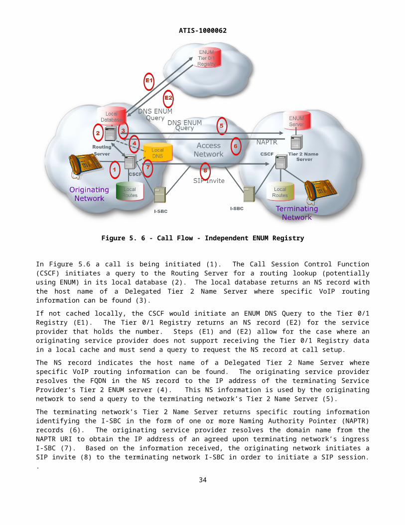
ATIS-1000062
Figure 5. 11 - Provisioning - Query using Independent Service Bureau Call Flow
5.5.3 Call FlowAn example of the Call Flow is shown below in Figure 5.12:
1. Pat (non-roaming subscriber of SP1) makes a session request (e.g., places a call) to Mike (subscriber of SP2). SP1’s network provides originating services based on Pat’s subscription.
2. SP1’s application server queries (2A) its routing service in real time using the called number to determine how to forward the request. The routing service first portability corrects the called number, and then determines that it is not subscribed to SP1. It then checks to see whether the code holder associated with the telephone number12 is covered by an IP interconnection agreement. If so, SP1 queries (2B) the Service Bureau specified by SP2, and the SP1 routing service (2A) supplies13 the application server with the ingress point through which SP2 has requested that session requests directed to this telephone number enter its network.
3. The application server identifies SBC-2 and (if applicable) SBC-1 in SIP ROUTE headers, and forwards the resulting session request onward. SP1’s L3 processing resolves the host portion of the topmost ROUTE header (using DNS) to the IP address of SBC-1.
4. SBC-1 removes the topmost ROUTE header (which identifies itself) and forwards the session request based on the next one (which identifies SBC-2). To do so it resolves (using DNS) the host portion of that header, yielding the IP address of SBC-2.
5. SBC-2 removes the topmost ROUTE header (which identifies itself) and admits the message to SP2’s network, forwarding it to an application server, and eventually to Mike. How SP2 performs these functions is SP specific.
12 The “code holder” is a term used to refer to the SP serving the TN, which can be identified in LERG data using the LRN or the NPA-NXX of the telephone number (if not shown in the NPAC, e.g., ported or pooled). 13 How this is accomplished is implementation specific. Messages from an application server to a routing service is typically an ENUM query, but in some networks a SIP message is sent to a proxy collocated with the ENUM service, which sends back a 302 “redirect” response.
34
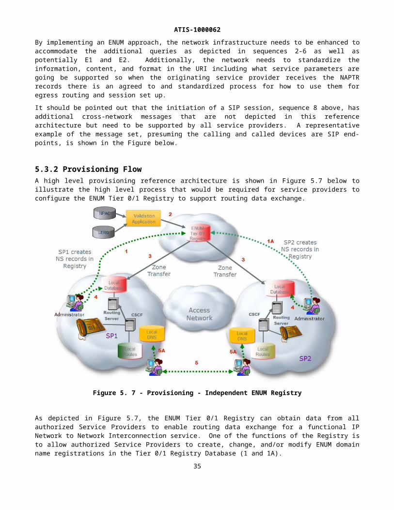
ATIS-1000062
Figure 5. 12 - Call Flow - Query using Independent Service Bureau
6 Interoperability Between Aggregate & Per-TN Routing Data Approaches
This section discusses how the two previously discussed carrier routing approaches can co-exist (or potentially interoperate) with each other.
When considering interoperating between carriers it is important to recognize that the interconnection process has a number of steps that are common. For example:
1. Interconnection agreements are formally negotiated between carriers on a bilateral basis. This negotiation process will lead to a formal agreement between the carriers on a number of key points related to the interconnection, including an agreed to mechanism for exchanging routing data. As a result, there is no need to define an approach where two carriers with arbitrary preferences interconnect and exchange data without first agreeing on the approach each will use.
2. Under all scenarios being considered, carriers will use data from a variety of sources as input to their internal BSS/OSS to build and maintain an internal database for routing calls/sessions. Each carrier uses their own system, with their own algorithm(s), for this, and it is therefore out of scope for this IP_ NNI Task Force. The routing data defined in this document is an important enabler for interconnection, but it is just one of the data sources used by the carrier to construct their own routing tables.
The key thing that differs between the proposed solutions is what specific data is to be exchanged between carriers as part of interconnection negotiation. This is an important aspect that has already been discussed in this document and it is assumed for this interoperability section.
Specifically, this section covers the case where carriers prefer to use different approaches and outlines a series of intermediate options that discuss potential industry “middle ground” positions.
35

ATIS-1000062
6.1 Routing Data From an Aggregate SP To a Per-TN SPThere are several possibilities for how the per-TN SP may arrange to route to the Aggregate SP.
First, the Per-TN SP may simply agree to implement aggregate-based routing as described in Section 4.
The second alternative is to transform the aggregate routing data into a per-TN representation. In the basic case, a per-TN SP receives the aggregate data and then creates individual TN records in its routing server based on that data. For example, if an OCN to SBC IP address mapping is provided, the per-TN SP uses associated industry data to map the OCN into the set of TNs the aggregate SP is offering for IP traffic exchange. This involves determining the set of NPA-NXXs and/or thousands blocks under the OCN, creating a record for each TN, and then continuously removing records for numbers that have ported or pooled away from the aggregate SP and adding records for numbers ported or pooled into an LRN that is associated with the OCN (i.e., has an NPA-NXX with the code holder OCN of the aggregate SP). Thus, it is the responsibility of the Per-TN SP to update the record set based on changes industry data. Note that the expanded data set may include records for unallocated numbers. Except for misdials, these records would not be accessed.
The expansion described above could also be performed by a third party, either on behalf of the per-TN SP or the aggregate SP depending on business arrangements.
In the third party case the aggregate data could be delivered to a service bureau by the aggregate provider. Because the service bureau could distribute data to multiple per-TN providers records would not include IP addresses as these would be target service provider specific. The records however could map TNs to a supplied SIP URI with a generic host name keyed to the aggregation element provided in the bilateral exchange. For example, a SIP URI containing the hostname OCN “<ocn>.<spname>”.net might be used in the service bureau records. The per-TN provider could then populate the TN records in its routing server as described in Section 5 and resolve the host name in its local DNS, with records that match the host name to the IP address associated with the corresponding OCN in the bilateral data exchange.
6.2 Routing Data From a Per-TN SP To an Aggregate SPThere are likewise several possibilities for how an aggregate SP may route to the per-TN SP.
First, the per-TN provider may simply agree to provide aggregate routing data. Aggregate data may include TNs beyond those for which the per-TN SP prefers for IP interconnection. For example, a wireless SP that has both VoLTE (IP) and GSM/UMTS (non-IP) subscribers that are not distinguished from a NANP data construct view may simply provide mappings from, for example, its OCNs to its SBC IP addresses. This will result in some VoLTE originated calls transiting the IP interconnection even though they are destined for GSM/UMTS subscribers.
A second possibility is that the aggregate SP will accept per-TN information to populate its routing server even though it prefers to provide routing information for its own TNs on an aggregate basis. The per-TN data could be provided through a service bureau.
6.3 Registry Supporting Both Aggregate & Expanded per-TN Routing Data In this case the aggregate input would map a NANP construct to a SIP URI rather than a set of IP addresses (as discussed in Section 6.1 above). Bilateral negotiation would then provide the URI to IP address mapping. A Registry could retain this aggregate input and make it available to SPs that prefer aggregate input via an interface to be defined. It could also expand this aggregate input and make it available to SPs that prefer per-TN data.
6.4 Using the NPAC to interoperate on a per-TN and aggregate basis6.4.1 OverviewThe solution introduced in this section assumes that some service providers will agree to use an aggregate routing data approach and others a per-TN routing data approach. The solution identifies just one potential
36

ATIS-1000062“middle ground” for industry consideration. It leverages the NPAC and approved North American Numbering Council (NANC) governance change orders designed to facilitate routing transition to next generation networks. The solution further draws on established practices and commercial third party offerings which have been enabling ubiquitous Short Message Service (SMS) routing, for example, across a broad range of specialized use cases. Specifically, this solution focuses on an approach for supporting the provisioning of both aggregate and per-TN level routing data into the NPAC and distributing it all at a per-TN level for consumption by any authorized service provider.
6.4.2 High Level DescriptionA key difference between the two currently proposed routing data approaches in Sections 4 and 5 is the granularity of information to be provisioned (shared) and managed by each service provider’s routing service. However, once some service providers agree to use a per-TN data approach, then all other participating service providers will most likely need the capability to manage the associated per-TN data in their respective routing services.
The following solution is just one way to support the provisioning of both per-TN and aggregate routing data in the NPAC and builds on various third party services and published APIs that primarily support ubiquitous industry SMS routing today. The following description assumes that certain one-time activities previously discussed and common across both proposed routing data approaches have already taken place between service providers (e.g., IP connectivity established). This solution supports both per-TN and aggregate routing data input and expands the latter for direct provisioning into the NPAC.
It should be noted that this solution can support the NPAC in the role of either a Tier 1 (i.e., routing data in a format that identifies service provider Tier 2 servers – see also Section 5.2) or Tier 2 (i.e., routing data in a format that identifies an interconnect SBC, or I-SBC, domain, where the specific “trunk group” or “route” is ultimately designed through a bi-lateral service provider information exchange – see also Section 5.1). The remainder of this solution description assumes a Tier 2 role, where the routing data to be exchanged in the NPAC is in the form of a SIP URI like “sip:<telephone number>@sbc1.sp1.com”. However, the solution doesn’t rely on just this specific URI format.
6.4.3 ProvisioningGenerally, the NPAC Location Routing Number (LRN) for ported telephone numbers or NANP NPA-NXX for native telephone numbers is used to route calls between service providers. Similarly, the NPAC Service Provider Identification (SPID) or NANP Operating Company Number (OCN) is typically used to route text messages between service providers. Over the past five years or so, multiple commercial wireless use cases have arose where the SPID or OCN associated with a particular telephone number in these recognized authoritative databases (after port-correction) was not sufficient for routing within the ecosystem. Further, these authoritative databases, at the time, were limited in their support of such use cases. Consequently, several commercial third party services were introduced to support these use cases while they work hand-in-hand with the recognized authoritative databases.
The key constraint in the NPAC has since been removed through one NANC governance change order that allows native telephone numbers and associated information to be stored in the NPAC. The PSTN to IP transition use case and others being discussed are analogous to those that have naturally evolved around text messaging where additional information beyond an NPAC LRN or NANP NPA-NXX is required in support of routing. The provisioning flow summarized below uses the NPAC in support of the use case(s) minimally discussed within this ATIS/SIP Forum IP-NNI Task Force. Specifically, it proposes to use the industry-approved VOICE URI field that is one field of many in the existing, standard NPAC database record. Further, it leverages at least one established commercial third party service to provision and maintain NPAC database records with URI field data inherently synchronized with aggregate routing data input.
Figure 6.1 below highlights the provisioning and distribution aspects of the solution. For illustrative purposes and in an attempt to just give the reader an introduction to how the solution can work, the aggregate routing data input is assumed to be in the form of an NPA-NXX (a native NANP 6-digit code or 6-digit LRN). Further, SP1 has agreed to use the per-TN routing data approach while SP2 wants to provision routing data at an aggregate level.
37
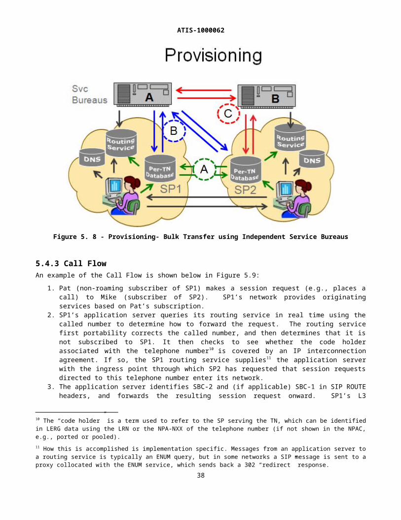
ATIS-1000062
-
Figure 6. 1 - Provisioning
Using the NPAC to Interoperate on a per-TN and Aggregate Basis1. SP1 and SP2 negotiate bilateral IP interconnection and exchange. In support of routing data exchange,
each provides an agreed to mapping of IP address records (A/AAAA records) to FQDNs (or URI domains) corresponding to their respective I-SBCs. Each SP then provisions these records into their respective local DNS. An example of such a mapping for one URI domain could be:
URI Domain IP Address
sbc1.sp1.com 138.34.23.3
sbc1.sp1.com 182.36.12.1
sbc1.sp1.com 58.23.12.90
2. SP1 populates the NPAC VOICE URI field in the associated subscription version (SV) record through its SOA (or equivalent) as new numbers are provisioned or existing numbers become available for IP interconnection. Again, the routing data to be exchanged is assumed, for this description, to be in the form of a SIP URI like “sip:<telephone number>@sbc1.sp1.com”.
3. SP2 shares aggregate routing data with an established third party service. For example,a. SP2 designates LRN 508-332 for IP interconnection.b. The associated ingress SBC domain is “sbc1.sp2.com”.
38

ATIS-1000062c. SP2 establishes a Letter of Authorization (LOA) with the third party supporting this solution (if
such an LOA doesn’t already exist).d. The LRN/ingress SBC domain/Action is then shared with the third party service over one of
several published APIs (e.g., a flat file with a row “508332,sbc1.sp2.com,A” where “A”=Add).4. The third party service for SP2 expands aggregate routing data input and manages as per-TN VOICE URI
field data in the NPAC on behalf of SP2. For one example use case, a. Third party service interprets row “508332,sbc1.sp2.com,A” in a shared flat file and generates the
associated NPAC provisioning actions. For example,i. 15 numbers (SV records) were found to exist in the NPAC with LRN 508332XXXXii. 15 Modify actions are then generated to add “sip:<telephone number>@sbc1.sp2.com” to
the VOICE URI field for these SV recordsb. At a configured interval (e.g., every 15 minutes), check for new numbers with LRN 508332XXXX
and generate associated Modify actions. Note that there is no action required for those numbers that are no longer associated with this LRN.
5. SP1 and SP2 download per-TN VOICE URI field data from each other (along with other existing NPAC data for number portability) through its LSMS (or equivalent).
6. SP1 and SP2 extract per-TN VOICE URI field data from each other (along with other existing NPAC data for number portability) and provision it into their respective internal route servers. Note that the details of how this routing data gets represented and used are specific to SP1 and SP2.
6.4.4 Call FlowFigure 6.2 below illustrates a call flow with the proposed solution. For illustrative purposes, SP2 initiates a call (session) to SP1:
Registry
InternalRouteServer
InternalRouteServer
SP2 customer calls SP1 customer
SP2 SP1
NPAC
4
2
LocalDNS
LocalDNS
1
CSCF
CSCF
657
I-SBCI-SBC
3
Figure 6. 2 - Call Flow - Using the NPAC to Interoperate on a per-TN and Aggregate Basis
1. SP2 customer dials destination number on SP1 network.2. SP2 S-CSCF queries internal route server and SP2 route server responds back to S-CSCF with a port-
corrected SIP URI containing the hostname of an agreed upon SP1 interconnect SBC.3. SP2 S-CSCF resolves this hostname in the SIP URI through its local DNS to obtain the IP address of the
SP1 interconnect SBC.4. A SIP INVITE is sent to SP2 interconnect SBC that has layer 3 connectivity to the SP1 interconnect SBC.
39
ATIS-10000625. The SIP INVITE is forwarded to the SP1 interconnect SBC.6. SP1 interconnect SBC forwards the SIP INVITE to the SP1 S-CSCF. 7. SP1 S-CSCF terminates the call to its customer.
6.4.5 SummaryThe solution proposed above is just one potential “middle ground” for industry consideration. It is instantiated over existing NPAC infrastructure and conforms to approved/adopted change orders. Using the NPAC to support the PSTN to IP transition use case (and others being discussed) also allows inherent data synchronization with number portability information. Further, the solution has built-in support for local downloads/caches of routing data. The solution is transparent to service providers who agree to use the per-TN routing data approach. For service providers who agree to use the aggregate routing data approach, the associated aggregate routing data (e.g., native NPA-NXX, LRN) can be shared through an established third party, expanded, provisioned and updated (on their behalf) as per-TN routing data in the NPAC. This per-TN routing data can then be directly consumed by any participating service provider.
40

ATIS-1000062
Appendix A - Comparative Characteristics MatrixThe ATIS SIP FORUM IP-NNI Task Force developed the following list of comparative characteristics that may be useful in understanding the approaches discussed in this document.
# Characteristics Group Characteristics Information
type
1 Performance Scalability List issues & quantify
2 Reliability List issues & quantify
3 Call setup time Value range & conditions
4 Impact on signaling traffic Quantify
5 Service requirements Ability to specify interconnection information with finer granularity than at the service provider level
Yes/No
6 Ability to specify different interconnection attributes for different groupings of a service providers’ numbers
Yes/No
7 Provides a mechanism for aggregation of routing information above the individual number level.
Yes/No
8 Provides a mechanism to get some insight into the service capabilities of destinations before routing a call.
Yes/No
9 Supports the ability to provide GETS. Yes/No
10 Provide a mechanism for interconnecting carriers to identify different interconnection points (for a given group of TNs) depending on the originating carrier.
Yes/No
11 Enables the service provider connecting to the terminating provider to select the interconnect point, consistent with the preferences identified by the terminating carrier.
Yes/No
12 Provides the ability to exchange routing data between carriers in bulk.
Yes/No
13 Provides the ability to query a locally cached copy within each carrier, rather than always having to query the terminating carrier.
Yes/No
14 Provides a clear path to a global solution Yes/No
15 Provides a good solution for the end-state all-IP network
Yes/No or degree?
16 Maintains backwards compatibility or method to interoperate during the transition to an all-IP network
Yes/No
41
ATIS-1000062
17 Ability to support non-E.164 public user identities Yes/No
18 Solution synchronized to number portability Yes/No
19 Solution not tied to historical geography of numbering plan
Yes/No
20 Support for open Internet routing Yes/No
21 Solution complexity Time to implement – common infrastructure Quantify
22 Impact on core network elements? Enumerate & quantify
23 Impact on existing service provider systems Enumerate & quantify
24 What external bodies are required to modify existing arrangements, systems, etc.?
Enumerate
25 Impact on existing industry systems Quantify
26 Level of dependence on “CO codes”, even during the transition?
Quantify
27 Need for additional industry systems & interfaces? Quantify
28 Security Increase in vulnerability Quantify
29 Support for secure tunnels Yes/No
42