athletics facilities master planning: introduction the louis s. madrid sports complex, ... planning...
TRANSCRIPT

Athletics Facilities Master Planning:
Introduction
University of Wyoming
FINAL March 28, 2012

University of Wyoming Sink Combs Dethlefs
Athletics Master Plan Sports Architecture Introduction.1
Background
As the University of Wyoming approached the 21st
century, Cowboy Athletics embarked on a
fundraising and building program that has significantly improved the facilities that support each
student-athlete’s quest to perform at their best. The Rochelle Athletics Center set a new standard
for facilities and expectations. Jonah Field, the new Indoor Practice Facility, the new Indoor Tennis
Facility, the Louis S. Madrid Sports Complex, and the recently completed Wildcatter Club & Suites
along with a variety of other venue improvements have continued Athletics’ development of
competitive facilities. Yet, the work is not complete. The Department of Athletics, Facilities
Planning, and Sink Combs Dethlefs have collaborated on the Athletics Facilities Master Plan, which
has focused on three primary facilities and the programs they serve.
The Arena-Auditorium (A-A) is notorious for its raucous home team atmosphere. But, from a fan
and revenue standpoint, it lacks the amenities needed to transform a great basketball setting into a
high-performing revenue producer for the program and the University. The new master plan will
help create the vision for this transformation.
Like the Women’s Tennis program, the golf programs are challenged by Laramie’s climate. Creating
a new indoor practice facility for the golf teams will add significantly to the quality practice and
training time available to the coaches and student-athletes.

University of Wyoming Sink Combs Dethlefs
Athletics Master Plan Sports Architecture Introduction.2
Finally, the Swimming and Diving teams require a highly specialized and competitive environment
for practice, training, and competition. Planning for state-of-the-art aquatics facilities is a must to
stay competitive within the conference and nationally.
UW is a unique university. The altitude, climate, and the passions of the entire state combine to
create a revered and cherished athletics program. To build on its great tradition of success, UW
Athletics must be prepared to address further challenges. Facilities will play a major role in many
of these challenges. Having the right environment in which to learn, train, coach, practice,
compete, and excel is absolutely essential. It is extremely important that we develop a plan for
facilities that truly fit the Pokes: quality facilities that support the culture and goals of the
University. Facilities must be:
• targeted yet adaptable
• efficient to build and to operate
• state-of-the-art with a reverence for the culture that distinguishes Wyoming Athletics
• highly functional to maximize student-athlete training and skill development
• effective for each student-athlete and for the broader communities of campus, Laramie,
and the state
The traditions of success at Wyoming seem best reflected in the traditional architecture in the core
of the campus near Prexy’s Pasture. Like many campuses, some of the athletic facilities, particularly
the Arena-Auditorium, do not reflect the same identity and architectural commitment to the iconic
“UW style.” As part of the Master Plan process, the analysis dealt with functional requirements of
size, relationships, and existing infrastructure and facilities. This study was also respectful of
campus planning and architectural design principles that can positively impact the campus
environment. The athletics facilities must continue to become an engaging part of campus.

University of Wyoming Sink Combs Dethlefs
Athletics Master Plan Sports Architecture Introduction.3
Master Planning Process
The University established a steering committee to direct the decision-making process for the
Master Plan. Members of the committee included:
• Tom Burman, Director of Athletics
• Matt Whisenant, Deputy Director of Athletics
• Randy Welniak, Sr. Associate AD, Development/Revenue Enhancement
• Bill Sparks, Sr. Associate AD, Business Operations
• Molly Moore, Sr. Associate AD for Internal Operations/SWA
• Bill Hamilton, Associate AD, Event Management
• Roger Baalman, Director of Planning
• Jim Scott, Director of Physical Plant
• Frosty Selmer, Deputy Director, Utilities Management
• Luke Ruff, Student Athlete
The consultant team for the primary; facilities of the arena auditorium, aquatics and golf included
Sink Combs Dethlefs, sports architects, Counsilman Hunsaker, aquatics consultants, WJHW,
audio/visual and IT consultants, ME Engineers, mechanical and electrical engineers, and
Martin/Martin, structural engineers.
Steering Committee meetings occurred roughly once per month from April to February 2012 The
master planning by the consultants focused specifically on three projects:
• Improvements to the Arena-Auditorium
• Improvements to Corbett Pool
• And a new indoor golf practice facility at Jacoby Golf Course
The process began with analysis of the existing facilities and a simultaneous series of stakeholder
interviews to develop programmatic needs. The needs were documented through the
development of outline programs for each of the projects, focusing primarily on the sizes of and
relationships between spaces needed to fulfill the program objectives. Site analysis played a critical
role in the development of the visions for each of the three projects, as did cost analysis.
The consultant team interviewed representatives from the following stakeholder groups:
• Men’s and Women’s Golf
• Men’s and Women’s Basketball
• Men’s and Women’s Swimming and Diving
• Sports Medicine
• Strength & Conditioning
• Equipment Services
• Media Relations
• Arena Operations
• Food Service/Concessionaire
• Facilities Planning
• Physical Plant
Meeting minutes of the interviews may be found within the appendix.
University of Wyoming Sink Combs Dethlefs
Athletics Master Plan Sports Architecture Introduction.4
Overall Master Planning Objectives
Essential to the successful completion of the master plan was early establishment of overall master
planning objectives. During the first work session in April, the Steering Committee established a
series of overall planning objectives for the consultants on the three projects and similar objectives
for the remaining projects within the master plan:
The master plan should reflect a planning horizon of ten to fifteen years. It must
be a guiding document that will facilitate UW’s continuing quest for excellence.
Funding is critical to the implementation of any of the athletic projects. This
Master Plan should not only outline the program and implementation vision for
each of the athletic projects, but deliverables should include illustrative images
that can be used to solicit University and legislative support as well as spur
private giving.
The National Collegiate Athletic Association (NCAA) Division I environment is
dynamic, as evidenced by the past two years’ reconfiguration of conferences
across the nation. As the University looks to the future, building a solid
foundation of facilities will assist Cowboy Athletics to remain competitive and to
generate the revenues required to consistently compete at a high level in all
sports.
Ultimately, the success of the Athletics program is defined by the success of the
student-athletes, individually and collectively. This master plan must envision
the facilities needed by coaches and student-athletes to consistently set and
achieve new standards of success. Greater success is instrumental in cultivating
the great relationship the Athletic Department has enjoyed with the people of
Wyoming.
Guided by the above objectives and using a collaborative, creative, and proactive process, a new
vision has been developed for specific athletics facilities that are tailored to UW’s campus,
traditions, and future.
Within the following pages, goals specific to each of the athletic projects are detailed as are the key
elements that define the visions and their ensuing implementation.

APPENDIX Pages
Stakeholder Interview Meeting Minutes 1-13
Dome Structural Report 14-16
Audio/Visual Narratives 17-49
MEP Narratives 50-54
Aquatics Narrative 55-65

University of Wyoming Sink Combs Dethlefs
Athletics Master Plan Sports Architecture Appendix.1
University of Wyoming Athletics Master Plan Needs Analysis Interview:
Academics:
To meet your longer term goals, what activities or facilities will be needed to support your program?
• No academic requirements. Provide a few work stations for brief work sessions, not
academic programming. Keep academic programming centralized.
• Include ADA access to all facilities, especially on the rehab side. Other teams may come in
and use the pool for other work-outs. Build the pool to handle swim lessons, recreational
uses, team uses.
• Alternate arena uses. Limited by scheduling, permanent floor.
Are there other needs you, your staff, or your student-athletes have that are reliant on facilities?
• No.
University of Wyoming Athletics Master Plan Needs Analysis Interview:
Joe Jensen, Head Coach M&W Golf
Name of Program/Department: M&W Golf, First Tee Program for Youth (200 participants), HS
teams, students, members. The “fruit salad” for everyone. A home for everyone.
Number of Student-athletes served (team size or number/gender of sports): 10 M, 10 W
Number of coaches/staff: 1 HC, 1 ass’t plus an ass’t mgr for the course. FT/PT/GA? All FT
How will you define success in 5-10 years? How does that compare to the current situation?
• Currently: weather issues have a strong impact on the ability to service all members of the
golf community. An indoor facility will provide revenue opportunities in terms of donor,
member, or community use. 28,000 rounds per year. Season starts in April, ends in late
October. An indoor facility will add 30-45 days on each end. Indoor hitting will provide
year-round use.
• The golf course is a self-sustaining facility. The new indoor facility should also be self-
sustaining. Potential need for an endowment. Naming opportunities for hitting bays, the
building, etc. Potential donors will expect a certain quality. Not a Taj Mahal, but consistent
with UW.
• Can move a green or trees to make it all work better. No capital funding, so Golf doesn’t do
much in the way of improvements. Original irrigation system still in place. Needs to be
replaced. The practice experience has become a significant part of the golf experience.
• For the team, being able to practice indoors will help immensely. Only school other than
San Diego State University without an indoor practice facility. Having the facility will likely
reduce the travel burden.

University of Wyoming Sink Combs Dethlefs
Athletics Master Plan Sports Architecture Appendix.2
To meet your longer term goals, what activities or facilities will be needed to support your program?
• Practice: Year-round hitting bays, 4-5. Indoor putting facility. Big, flat and square—30-40’
putts minimum. Chipping: create amenities around the building—artificial surfaces that
can be year round from hitting bays. Add a lot of storage. Lots of team practice, but also a
lot of individual practice/training. 20 hrs/week maximum coach/player contact. To
succeed, kids need more practice time than that.
• Strength & Conditioning: Access to the RAC. No need for weight training in the building.
• Sports Medicine/Practice Prep/Treatment: same philosophy as training.
• Meeting: Team room concept is important. Could also function for hospitality events—
cocktail parties, etc. Expose the building, program, services, and meet the kids. Classroom
for First Tee meetings/instruction.
• Coaching (offices, video analysis, etc.): space for Exec Dir of First Tee program, coaches’
work space (not a replacement of offices), 1 business manager office (would free up an
office in the clubhouse).
• Technology Integration: Cameras from four directions in two bays minimum, launch
monitor, flat screens for teaching. Golf simulator is useful—could create a winter league—
climate controlled separately from hitting bays; chairs behind for foursomes/spectators.
Allows the ability for training year round.
• Locker/Dressing Rooms: Bag storage for athletes. May be an opportunity for fundraising.
• Equipment Issue/Laundry/Repair: Club repair station would be used, but is not a high
priority. A “nook” space.
• Academics: Very important part of the golf program. Work stations within the Team Room.
• Recruiting: Team room. 3 academic All-Americans last year. Wireless technology. A place
where kids can go and study and lean on one another on the academic side. First
impression from exterior will be very important. Match the UW standard.
• Public use: create an area for members or others to enter and wait for hitting bays, etc.
Potential for bag storage. Golfers who will use this facility will pay more and will likely
expect access to instruction.
Are there other needs you, your staff, or your student-athletes have that are reliant on facilities?
• Potential for Nike sponsorship.
• Make it part of a complex of indoor and outdoor practice areas. Provide a tee surface just
outside the building.
• Hall of Fame component in lobby.
Examples: Texas A&M, Air Force, Troon Golf

University of Wyoming Sink Combs Dethlefs
Athletics Master Plan Sports Architecture Appendix.3
University of Wyoming Athletics Master Plan Needs Analysis Interviews:
Tom Burman, AD Men’s Basketball
Name of Program/Department: Men’s Basketball
Number of Student-athletes served (team size or number/gender of sports): 15 max.
Number of coaches/staff: 1 HC, 3 Ass’ts, all FT + FT FT/PT/GA? No GA’s
How do you define success for your program today?
• Better the comfort in their offices. Add an entryway. Sell some exposure to the court.
Offices, Strength and Conditioning, etc. Develop an entryway that is really first class.
Natural light, ticket office, hall of fame, etc. Arena scoring, lighting, video would be top
priority.
• Create a social club area.
• Develop a certain look. Like UNM, CU, etc. An entryway. Sex appeal of facilities is number
one, no questions. Link facilities visually. Locate coaches offices and club off an entryway.
Lifting in the RAC is preferable because of the light and views. Strength inside the arena
would be a big plus to prospective student-athletes.
• A dining facility could be of huge benefit. A centralized eating location with views to the
arena. Good nutrition. NCAA limits it to one meal per day. Open it up to the University for
breakfast and lunch?
How will you define success in 5-10 years? Will that change how your program operates or interacts
with other programs?
• Recruiting will be more challenging. Facilities will play a bigger role. Facilities are good.
Need all the new bells and whistles. Ribbon Board, etc.
• Create a dedicated video control room in the arena.
To meet your longer term goals, what activities or facilities will be needed to support your program?
• Competition: The portal is great.
• Practice: Create additional floor space for practice—highest priority. Very challenging as is.
More baskets. Allow full-court setting plus individual work to the side. 6 total baskets ideal.
• Training: Weight room should have a different look—modernization. Need splash . Make
larger. Keep consolidated with locker rooms. Ceiling height is an issue.
• Sports Medicine/Practice Prep/Treatment: Weight room should have a different look—
modernization. Make larger. Keep consolidated with locker rooms.
• Meeting: Coaching (offices, video analysis, etc.): Coaches need an area to go.
• Technology Integration: Game day: add another video board to serve west side seats.
Wants instant stuff—stats. Enhance the video. Ribbon board—good for stats, scores, as
well as advertising. Make it a more interactive fan experience. Have to compete with the
quality of broadcasting. Camera locations/angles: 6-8 typically for games. Show the fans
all the angles. Distribute cable permanently. Currently, everything is moved out to the
arena—laptops, etc. Immediate live carts not necessary. It’smore about day-to-day
efficiency.

University of Wyoming Sink Combs Dethlefs
Athletics Master Plan Sports Architecture Appendix.4
• Video/practice. Create a combined film room for men’s and women’s basketball (men’s
space is tight). Viewing area for the team. Locate everything as close to the same space as
possible. Proximity of coaches’ offices not important. Wire everything so it works
efficiently. Each coach does their own video currently.
• Locker/Dressing Rooms: Locker room structure works very well. Move soccer to a different
location.
• Equipment Issue/Laundry/Repair: Add a facility to the A-A. Shared use with other teams.
Currently hauling everything over to the RAC.
• Academics: Keep it in the RAC
• Recruiting: Light show, laser lights, spotlights, make it all about the recruits.
University of Wyoming Athletics Master Plan Needs Analysis Interview:
Joe Legerski, HC W Bball
Name of Program/Department: Women’s Basketball
Number of Student-athletes served (team size or number/gender of sports): 15 max.
Number of coaches/staff: 1 HC, 3 Ass’ts, all FT + FT web design FT/PT/GA? No GA
How do you define success for your program today?
• Win…graduate all kids. Recruit well. Recruiting competition… regionally, internationally..
CU, CSU, DU, etc.
• Facilities play a role in recruiting. Fan attendance is more important. Facilities make a
bigger difference to the fans. Draw 4-5,000.
• A high def center-hung scoreboard. Create something that make people get off the couch
and come here.
How will you define success in 5-10 years? Will that change how your program operates or interacts
with other programs?
• Recruiting will be more challenging. Facilities will play a bigger role. Facilities are good.
Need all the new bells and whistles. Ribbon board, etc.
• Reduce seating capacity to 8-10,000 to make the building look more full . Create a better
atmosphere. Would play in a 4,000 seat facility if possible. Add suite or club seating.
Brighten/enliven the concourse. Entryway to the arena: combine with a hall of fame. Walk
into a place that jogs your memories, rather than a sterile environment. Relocate ticket
office. “Front door” is currently on east side. Long-term parking will stay to the east of the
stadium. Parking structures in the long-term. A centralized ticket office would work for
Basketball and football.
• Add padded seats in a premium section. With cup holders. Make those seats wider, if
possible.

University of Wyoming Sink Combs Dethlefs
Athletics Master Plan Sports Architecture Appendix.5
To meet your longer term goals, what activities or facilities will be needed to support your program?
• Practice: Create additional floor space for practice—highest priority. Very challenging as is.
More baskets. Allow full-court setting plus individual work to the side. 6 total baskets ideal.
• Training: Weight room should have a different look—modernization. Need splash. Make
larger. Keep consolidated with locker rooms. Ceiling height is an issue.
• Sports Medicine/Practice Prep/Treatment: Weight room should have a different look—
modernization. Make larger. Keep consolidated with locker rooms.
• Coaching (offices, video analysis, etc.): a low priority. Very good set-up.
• Technology Integration: Game day: add another video board to serve west side seats.
Wants instant stuff—stats. Enhance the video. Ribbon board—good for stats, scores, as
well as advertising. Make it a more interactive fan experience. Have to compete with the
quality of broadcasting. Camera locations/angles: 6-8 typically for games. Show the fans
all the angles. Distribute cable permanently. Currently, everything is moved out to the
arena—laptops, etc. Immediate live carts not necessary. It’s more about day-to-day
efficiency.
• Video/practice. Create a combined film room for men’s and women’s basketball (men’s
space is tight). Viewing are for the team. Locate everything as close to the same space as
possible. Proximity of coaches’ offices not important. Wire everything so it works
efficiently. Each coach does their own video currently.
• Locker/Dressing Rooms: Move a locker room into the arena. Combined locker/lounge pace
works well. Use existing locker room as a model for master planning, without the separate
lounge space. No academic needs within the locker room.
• Equipment Issue/Laundry/Repair: Add a facility to the AA. Shared use with other teams.
Currently hauling everything over to the RAC.
• Academics:
• Recruiting: Office location not important. At other places, kids notice: ribbon boards, logos
flashing, clear identity, practice facility banners hanging, VT locker rooms (does it have
TV’s?).
University of Wyoming Athletics Master Plan Needs Analysis Interview:
Media Relations: Tim Harkins
Name of Program/Department: Media Relations
To meet your longer term goals, what activities or facilities will be needed to support your program?
• Competition: Pre-wire the arena for television. Currently they have to pull a lot of cable.
Wire it also for video board production people. Create a separate video control room to
eliminate the use of the trailer. Find a better spot than the press table for the video control
people (within the video control room). Post-game interview room: works fine. Does not
work well for the coaches’ show (currently have to locate the camera outside the door).
Combining those two functions is efficient for the TV production staff. Create a small room
for VT post-game interviews. Create a dedicated copy room (low priority). Scoreboards:
include stats. Press location is ideal and very functional. Good access to internet and
power.

University of Wyoming Sink Combs Dethlefs
Athletics Master Plan Sports Architecture Appendix.6
• Media hospitality:
• Increase size of door to better accommodate TV trucks. Trucks can stay outside once the
permanent wiring is in place. Park an ambulance inside the doors also. Treat the broadcast
needs well.
• Not yet fiber, but it will move that direction. Important if centralized control room.
Wireless access throughout is important (exists).
• All TV partners do games in HD. Need fiber lines from camera positions to the video control
room.
• Tournaments don’t present any extra issues.
Arena Operations:
Bill Atencio, Bill Sparks
To meet your longer term goals, what activities or facilities will be needed to support your program?
• Add storage: currently rent three bays of storage of site. Portable backstops.
• Events: Basketball. Commencements (UW, HS, and WyoTech) require floor covering, staging
areas, backdrops, plus trailer. 500 students on the floor plus 2-3,000 people in the stands.
• Increasing size of the floor: Look at a different type of goal. Current goals not designed for
great mobility.
• Slope of ramp is OK. Use vehicles to move equipment up and back. Clearance either side of
main backstops is challenging. Moving scorer’s tables and courtside tables is challenging.
• Groundwater: Only lost floor once over last 17 years. Sump pumps at four locations.
• Ticketing: Minimal office in arena at the west entrance. Would like a main entrance that
would work for both football and basketball. Five windows. Need satellite locations—add
technology for real-time seat sales. Use Paciolan software. Would like a separate recruit
entry zone. No AC currently. Need some. Southwest as secondary entrance. Staff:
currently 4 cubicles plus an office for ticket manager plus vault. Add a work room. Include a
count room for concessions—could be shared with work room.
• First aid room is dedicated. Separate security room (not in arena). Landmark event staff
works out of one concession stand currently. Doesn’t work for interviews etc. Does work
to use concourse as employee orientation. Also use arena for basketball training.
• Brown and Gold vendor: merchandising. Would like to have two locations within the arena.
Gameday sales only.
• Fire marshal prevents use of concourse.
• Concessions would like to do food carts: popcorn, lemonade, ice cream, etc.
• Cowboy Joe Club has a storage room under the seats. Concessions also, facilities, and ticket
office.
• Fixed display cases in concourse should be removed. ADA issue.
• Aesthetic uniformity is important. Started a renovation program for a timeline.
• Branding: Excellence. Pride. Tradition. Wayfinding, landmarking, etc. would help.
• Hallway entry is heavily used.
• Lighting of the concourse needs improvement.

University of Wyoming Sink Combs Dethlefs
Athletics Master Plan Sports Architecture Appendix.7
Collin Vickers, Concessions (part of Athletics):
• Ripped out walls to increase points of sale (adequate for now). Hot dogs, nachos, pretzels,
popcorn, and sausages are the only current menu items. Need more power. Space for
popcorn poppers. 11 concession stands plus one used for storage. Four are operated by
outside vendors (pizza, Mexican food, ice cream, shaved ice—all prepared off-site). Bring in
materials from Fieldhouse Kitchen. One stand has an auto-fryer—that’s it for the Arena.
Each concession does not include prep space. Popcorn is done inside the arena.
• At stadium, catering is provided by a separate entity.
• No beer. Could do beer and wine in the club. Sodas are both bottle and canisters, depends
on whether the concession stand has water.
• A central kitchen would serve the Arena very well. 32 events in the AA each year. Kettles,
grills, fryers, freezer and cooler space.
• Credit cards/registers are important throughout. All hard-wired.
• Cater food into the hospitality room. Concessions provide drink, hot dogs, and chips and
salsa. Would like a kitchen that would allow catering items to be done on-site.
University of Wyoming Athletics Master Plan Needs Analysis Interview:
Facilities Planning/Physical Plant
Roger Baalman, Frosty Selmer, Jim Scott
• Ben Nelson: Structural capacity of Arena Auditorium roof. Unbalanced snow loading is now
required by code. Not required when roof was originally designed. The connections at the
joints are more the problem than the member sizes.
• The ability for the roof to handle unbalanced loads would be problematic, creating a change
of use and code upgrade.
• A traditional video board of 20,000 to 40,000 pounds would be far more stressful than the
unbalanced snow load. Looked at distributing the load, but would require modification to
the entire dome structure. Ben’s opinion is that it is not economically feasible to reinforce
the entire dome. The wood system is not very adaptable.
• Lighting ring is estimated to be 15,000 lbs. To match this weight with a video board would
not have the impact desired.
• Options: Self-supporting steel arch constructed inside the dome. Design it with excess
capacity to handle future possibilities. Will require abutments at either end or orient them
to align with the existing abutment walls. Installed on the interior presents some challenges
for construction, but the finished project is a better solution than an exterior application.
• Could provide a rigging structure.

University of Wyoming Sink Combs Dethlefs
Athletics Master Plan Sports Architecture Appendix.8
Corbett:
• Junky HVAC—very little AC. Full system needs replacement. VAV with lots of outside air
and heat recovery. Salvaged a heat pipe unit that is now on the roof to control
humidification. Gyms are used very little. All systems are original. Get more energy
efficient. Mid to late ‘70’s. Evap cooling is OK. Women’s basketball uses the gym more
than any other user/time.
• Steam provides heat. Steam in good shape.
• Pool filtration equipment. In pretty good shape. Access around perimeter of pool is
definitely desirable. Unless inflow is all from the bottom. Filter room can be removed. Tile
finish has gotten worse, but it hasn’t been bad over the years. Want longest life materials.
Acoustics is a big issue.
• Likely chlorine + UV + muratic acid. If the filtration is downstairs, provide an elevator.
• Equipment needs to be accessible and maintainable.
• Limited groundwater problems.
• Lighting has been replaced within one of the gyms. Look to high efficiency.
• Electrical: 13.2 kvA service. Large unit built by GE includes transformer, switchgear, etc.
Replace transformer? Plenty of capacity. Small gen set. Look at a larger one that would
serve more buildings.
• Energy use: LEED Silver as a minimum. Windows have no R-value. Potential for solar
thermal system?
• Digital controls are needed.
• Needs new EST system.
• Add natural light in the pool and gyms.
• Hydraulic elevator: still functional
• Pool must be accessible for public use.
• Hazardous materials. Hasn’t been surveyed. Asbestos is likely.
Arena Auditorium:
• Mediocre system. Does have vfd’s, high duct velocities. Heating and ventilation only. Room
for cooling coils, but not needed. Replace pumps. Replace/clean the coils. Air handlers are
under digital control. Need digital control throughout. Concourse as return air system.
Smoke control issue? May need fire sprinklering of dome?
• Electrical: need more power:
• 125 lb. steam. Lines run through basement corridor. Fire alarm; likely not compliant. No
strobes. No voice evac. Upgrade IRC panel.
• Back-up electrical HW heating system? Needed due to steam shut downs.
• Replace plumbing fixtures. Fixture counts are undersized. Infrared sensors on flush valves.
• Concourse lighting needs to be replaced. Exterior lighting needs to be redone. Snow
removal damage. 480 V fixtures are not good in this application.
• Irrigation water.
• Water entry. Has sheared off a couple times due to poor compaction. Concession stands
were waterproofed 20 years ago.
• Two forty horse pumps dewater bball floor. Could they go into a cistern for irrigation? Do
they need back-up? More moisture bulbs in building control system.

University of Wyoming Sink Combs Dethlefs
Athletics Master Plan Sports Architecture Appendix.9
• Ramps and accessibility issues. Floor acclimation has been an issue previously due to dry
environment.
• No humidification.
• IT: Plenty of infrastructure. No problems with scoreboard feeds. Security cameras are being
installed on the concourse. Plan for future card access to building doors (hardwired). JCI
system. Make everything web-based. Cameras at any point of 24-hour access.
• Room 4 is the core access for all of east campus.
• Lighting: keep it simple, but with atmosphere in arena. Occupancy sensors with manual
override. Tie occupancy sensors to the VAV’s. Natural ventilation is ideal.
• Gen Set: includes sump pumps and some of the heating pumps. Emergency exit lighting
needs to be replaced.
• Roger to send MEP plans.
• Hazardous materials less likely.
Golf Course. Jim Scott, Physical Plant Director
• New power tap. Extend gas line. No IT campus lines. Qwest. Map controls back into
campus system. Windy area. Sealed combustion water heaters. Radiant heating. Battery
packs.
• Potential location for NASA wind turbine. Residential scale—appropriate to this use.
• Irrigation issue is a priority, at $1.5 million cost. Maintenance facility location creates
staffing inefficiencies. Also not large enough to store the full 50 carts (20 are stored
outside). Practice facility used to enhance public golf experience as well.
• Don’t locate far from clubhouse. People will park at the parking lot an have to walk during
the winter.
Long Range Development Plan:
• West end of Willett Drive will terminate in a parking lot. Day-to-day end of Willett would be
at Athletics’ Drive. On game day, it would extend west to Greek quadrangle.
• Long-term parking structure south or west of Corbett.
• Parking lot between Fine Arts and Fieldhouse will become primarily green space.
• Practice fields/detention will be green forever.
• Visitor-oriented mixed use east of stadium parking. Parking structure on north half of
stadium parking lot. 22nd and Grand will become a major public campus entry. 15th Street
will be diminished in terms of campus access.
• Recreation/athletics needs to occur east of 22nd.
• Potential for future interchange off of 30th st—will push a lot more traffic onto 22nd.
• West side of Fieldhouse as potential pool site?
• Food service at NW corner of stadium?

University of Wyoming Sink Combs Dethlefs
Athletics Master Plan Sports Architecture Appendix.10
University of Wyoming Athletics Master Plan
Steering Committee April 13, 2011
Review Expressed Needs:
Consistent themes:
• Functionality/Keep it real.
• Focus on today’s needs
• Quality/Meeting UW standards/Identity
• Consolidation of support services, particularly Academics, Coaches’ offices, Player or patron
centers?
• Energy Efficiency
• Hospitality/Donor outreach
• Recruiting: Facilities matter for males moreso than females.
Important Strategic Considerations:
• Arena: influence of scoreboard/loss of seats? Scoreboard, lighting and sound most
important for basketball. Rigging capacity is not a high priority. As a campus facility, it has
to be multi-functional: graduations, University assembly events. Strong emphasis as a
practice facility. Fan amenities also very important. Jim: concerns for operation:
unoccupied, practice, event.
• Pool: Significance of needs vs. the existing facility
• Golf: Year-round use; Golf Practice as a revenue source
Next steps:
• Long-term goals/objectives for Athletics
• Food service for training table and events; nutrition as a component?
• Value of Corbett in terms of Swimming program vision
• Arena as more of a revenue source? Storage, Bball Practice, suites
• Accelerated timeline for golf
• Schedule next meeting:
• Look at alternatives to center hung board.

University of Wyoming Sink Combs Dethlefs
Athletics Master Plan Sports Architecture Appendix.11
University of Wyoming Athletics Master Plan Needs Analysis Interview:
Name of Program/Department: Sports Medicine/Strength and Conditioning
Trent and Bob
What other Athletics programs/services do you interact with on a regular basis? How and why?
• Both programs interact with the sports programs on a daily basis.
• Year-round sports. Extended training and rehab time.
• AA: Largest effect on S&C. Corbett and Golf not really in play. Lots of limitations in current
facility. If basketball only facility? Primary, but other sports may use. Create a large square
room, no columns or obstructions, high ceilings (28’ clearance is ideal for medicine balls).
Large double door for equipment move-in, move-out. No direct locker room access.
• Create a gathering area immediately inside door. A place where recruits can immediately
understand what the program is about. Or for full team presentations. 20 people. Create a
coaches’ area—an open work station. With small counters for work-out storage areas, files,
etc. 2-3’ deep lockers for storage of loose materials. DF’s at either end of room. Include a
supplement area. Gatorade tower with supplement storage for up to 700 bottles. Counter
for blenders and trash/recycling. Flooring with inset platforms. Sound dampening for
Olympic lifts. Technology: high speed treadmills, etc. ..wiring.
• 2,500 SF target. Equip. 6 x 8 platforms (5), 9’ high multi-use racks (5), cardio (15),
dumbbells, utility benches (5), lat pulls, open area with absorbing floor for jump training—
an aerobics floor with a durable (athletic flooring) med ball wall area (5 work stations in
each). Technology: easy, fast lights, centralized control behind work station. Maximum air
flow with great control, including dehumidification. Flat screen, taping, feedback. Acoustics
are important in the room and for separation from other spaces. Put the weight room on
the ground. Visibility from above into the weight room would be great. Cardio could go
upstairs.
• Coaches’ change area. Small room. Share with sports medicine. Create men’s and
women’s staff locker rooms.
• Training Room: in conjunction with the weight room. Could share cardio space. Also need
to be close to the locker rooms. Information sharing, etc. is important. Rehab area,
treatment are, hydro area, offices (3 separate: M & W, physician office/exam room). Exam
room large enough for 6-8 people plus benches plus a C-arm machine (portable—5’x5’) with
its own storage room. Sink with lockable cabinets. Cold plunge and a warm plunge.
Underground or above ground. 6x6 for each. Potential Hydroworks pool sized for
basketball players. Separate hydro with glass walls with humidity control. 4-5 treatment
tables. Share the rehab component (cardio plus plyo area). If separated, duplicate size and
equipment). Ice and Water room with storage for 12+ coolers plus two ice machines. A
large storage closet. Joint staff locker rooms with shower/toilet. Two taping stations, 5’
wide each, separate from treatment area. No stairs.
• Corbett: a room 20’x20’with an ice machine. 2 treatment tables, work station for trainer,
upper extremity wall unit, one office, no physicians room. This would change if in a new
facility combined with the high school.
• Golf uses the RAC for everything they need.
• Storage is critical for both programs.

University of Wyoming Sink Combs Dethlefs
Athletics Master Plan Sports Architecture Appendix.12
University of Wyoming Athletics Master Plan Planning Team Meeting:
Meeting Minutes June 24, 2011
Tom Burman, Roger Baalman, Bill Atencio, Bill Sparks, Joe Jensen, Jim Scott
8:00 Golf Practice Facility
Site/Floor Plan: Relocate building to be sheltered by trees adjacent to 18 green. Adjust
cart path. Enlarge chipping green.
Preliminary Renderings: Look at faux stone on lower portion of the building. Understand
Cost—get Roen to price ASAP. Upgrade soft costs to 40%. Utilities: Water in street. Gas at
clubhouse. Power as a separate drop. IT from clubhouse. Pump sewage or do septic. LEED Silver
equivalent. Native landscaping. Look at option of standing seam metal roof as a lifetime issue.
9:00 Competition Pool
Investigation of Corbett Expansion Look at pushing pool to the north. Parking to the north
eventually goes away. Maintain only fire access between the pool and the Fieldhouse. Relocate
entry so that parking access is from the east, not south. Replace classrooms with same capacity,
character. Dry land training can occur on the deck--allow for 50 students-athletes. Deck space
preferred. Can also accommodate tip and rolls for on-deck competitors. Include a coaches’ work
station/home base in either case. Visiting teams can simply use general student locker rooms. If a
remote site, high schools would use the general locker room. A competition pool first. 500 seats
OK.
Discussion of Alternate Sites: Tom: Funding may be more available with a new site. $20
million from legislature must have high school access. Corbett Pool expansion would be less
favorable. Thornton Pool at $15 million. A similar pool is desirable. Target $20 million project cost.
Detention pond site is less desirable. Could be located north of baseball and east of tennis. Share
the existing parking to the north, specifically for events. Provide limited parking on-site. Preferred
over Harney. Utilities are readily accessible. No problem with groundwater. Sandy soils with some
clay.
**Roger would like firm numbers for Corbett by 7/15.
10:00 Arena Auditorium
Updated Concept Direction Training Table: May need to precede the AA improvements.
Keep the training table. Carry suites forward as long term improvements.
Build Commissary with Training Table above as a smaller first project? Include basement with
Training and Strength. Capture views to the arena floor and the stadium from the training table.
Strength/Sports Medicine: prefer to have them on the same floor as the lockers.
Phase 2 would be the lobbies, concourse, club and raising of floor for practice. Also include video
board/scoreboard as a high priority.

University of Wyoming Sink Combs Dethlefs
Athletics Master Plan Sports Architecture Appendix.13
Locate offices like Option 1. Potential to locate offices inside bowl at top of ring beam???
**Take a hard look at ADA access to the floor.
No student seating behind visiting team. Locate students close to floor and behind HT bench on
northwest court. Clamshell to fill portal at centerline.
Move Soccer to Women’s Basketball Locker Room.
Locate public restrooms and media in service portal area.
Club access through Hall of Fame.
Phase 1: South east addition including sports med/strength at lower level, commissary/tix at
concourse level, training table above. Potential space for bball coaches offices? Include raising of
basketball floor, ADA mod’s and lower level renovations.
Phase 2: Scoreboard/ribbon board options
Phase 3: Club with east concourse/lobby expansion and coaches offices above. Renovation of
other concourse level areas.
11:30 Discussion/Direction/Next Steps
****Next meeting? Roger out July 22-27. Try to meet before Roger leaves, if possible. Check with
Roen and send out potential meeting dates to Zoe.

University of Wyoming Sink Combs Dethlefs
Athletics Master Plan Sports Architecture Appendix.14
March 14, 2011
Mr. Andy Barnard
Sink Combs Dethlefs
475 Lincoln Street, Suite 100
Denver, Colorado 80203
Re: University of Wyoming Arena Auditorium Study
Martin/Martin, Inc. Project No: #19095.S.02
Dear Andy:
At your request, we completed a cursory qualitative and quantitative assessment of the existing roof
structure of the University of Wyoming Arena Auditorium to support a future video/scoreboard
weighing approximately 40,000 lbs. We understand that our study will be blended into your overall
Athletics Master Plan, currently underway. Our study was based on the following:
• Graduate Student Report: “Nonlinear Buckling Analysis of the Arena Auditorium Located in
Laramie, Wyoming,” by C.D. Stauffer, April 25, 1992.
• Interviews with Patrick McManus, PE, SE, PhD; Lecturer-University of Wyoming and
Structural Technical Director of Martin/Martin, Inc.
• Martin/Martin, Inc. numerical analysis.
1.0 Discussion
Results and conclusions from the 1992 numerical analysis were helpful, although not conclusive for
the current Athletics Master Plan because of three limitations:
1. The scope of the report was primarily focused only on the global failure mode of two
loading conditions: (1) balanced uniform snow load over the dome, and (2) unbalanced
snow load on one half of the dome only. The 1992 finite element numerical analysis
concluded the unbalanced load case was more critical compared to the balanced load case.
The study did not investigate the dome’s ability to support a singular large point load from
the apex of the dome.
2. The study investigated the failure mechanisms (i.e. buckling of the individual dome
members) using classical mechanics theory but did not specifically examine the dome
structure subjected to Building Code requirements in Chapter 23 of the International
Building Code.
3. A design check of key wood-to-wood framing connections within the dome was not within
the scope of the study.
Even with the cited limitations of the 1992 study, three key points are useful to consider. The first
point is that the exiting roof dome structure is more susceptible to failure from unbalanced loading
compared to a uniform and balanced loading. Although not considered in the study, a large point

University of Wyoming Sink Combs Dethlefs
Athletics Master Plan Sports Architecture Appendix.15
load from a future scoreboard would introduce considerable stresses in a concentrated region of the
existing dome structure. Such a concentration of load will overload the existing dome structure.
The second key point to consider is the importance of the base condition of the dome itself. The
report cited only one boundary condition was considered and the stress results within individual
dome members were highly sensitive to the boundary conditions investigated. Suspending a
considerable load from the apex of the dome will introduce forces at the base of the dome that will
require strengthening.
A third point made by the report is the observation that domes are generally robust in their ability
carry loads in an efficient manner but that the Wyoming Arena Auditorium is a relatively ‘flat’ dome
shape, reducing the ability to carry a majority of load in compression of the dome members. A
‘flatter’ dome shape means that more of the roof load is carried by a combination of bending and
arch action of the dome.
After reviewing the 1992 numerical analysis report as well as interviews with Dr. McManus, we
believe it is possible to strengthen the dome to support the concentrated weight of a video board,
but that it could likely involve significant cost to do so. Not only would many of the dome’s wood
beams require strengthening, but significant effort would also be required to upgrade wood-to-
wood connections as well as the base connections. The connections suspended from the dome to
the video/scoreboard would have to be sufficiently distributed (spread out) to minimize large
concentrated forces at any one joint.
Supporting the proposed equipment from new structure constructed independently of the domed
roof structure is feasible and would alleviate the need to strengthen much of the existing dome.
Steel arches are proposed as a starting point and would likely be more economical compared to
wood arches. The arches could be installed either inside or outside of the existing dome roof.
Consideration of thrust forces at the base of the arches would have be addressed and could be done
so with the use of concrete walls similar to the existing walls around the Concourse level.

University of Wyoming Sink Combs Dethlefs
Athletics Master Plan Sports Architecture Appendix.16
2.0 Summary and Conclusions:
A. The existing domed roof structure of the Arena Auditorium was not designed to support a
concentrated equipment weight of 40,000 lbs from the apex of the dome. Although dome-
type structures are inherently robust, a concentrated load at its apex would significantly
overstress individual members of the dome as well as member-to-member connections in
the vicinity of the support points and base connections of the dome.
B. Strengthening individual roof members and member-to-member connections to resist
increased member stresses is feasible, although likely not economically practical given the
numerous members that would likely require strengthening.
C. Supporting the 40,000 lb video board could be supported independently from the existing
roof structure using a pair of steel arches erected inside the existing dome structure as
conceptually shown in the attached sketches. The pair of arches could follow the profile of
the existing dome and be founded on concrete walls (to resist the thrust) similar to the
existing concrete walls around the perimeter of the Concourse.
D. Supporting the 40,000 lb video board could be supported independently from the existing
roof structure using a pair of steel arches erected outside the existing dome structure in a
manner similar to the attached sketches. The pair of arches could follow the profile of the
existing dome and be founded on concrete walls (to resist the thrust) similar to the existing
concrete walls around the perimeter of the Concourse.
We appreciate this opportunity to be of service. Please call if you have any questions regarding this
report or if we may be of further assistance.
Respectfully Submitted,
C. Ben Nelson, P.E., SECB
Principal
University of Wyoming Sink Combs Dethlefs
Athletics Master Plan Sports Architecture Appendix.17
Table of Contents of AV Program Narrative
8.0 AUDITORIUM ARENA AUDIO VISUAL
8.10 Phase 1
8.11 Audio Systems
8.12 Broadcast Cabling Provisions
8.13 Multi-Channel Television Distribution System
8.14 Scoreboard and Video Display Systems
8.15 Scoreboard Video Production System
8.16 Broadcast Cabling Provisions
8.17 Opinion of Probable Systems Cost for Phase 1
8.20 Phase 2
8.21 Audio Systems
8.22 Multi-Channel Television Distribution System
8.23 Opinion of Probable Systems Cost for Phase 2
8.30 General for All Phases
9.0 CORBETT POOL AUDIO VISUAL
9.01 Main Sound Reinforcement System
9.02 Control Location
9.03 Public Circulation Sound
9.04 Paging
9.05 Team Locker Rooms
9.06 Hearing Impaired and the ADA Requirements
9.07 Life Safety Interface
9.08 Conduit and Raceways
9.20 Multi-Channel Television Distribution System
9.21 Satellite Reception and Transmission
9.22 Concessions Televisions
9.23 Televisions in Concourses and other Areas
9.30 Scoreboard and Video Display Systems
9.40 Broadcast Cabling Provisions
9.41 Camera Locations
9.42 Broadcast Cabling System
9.43 TV Mobile Production Unit Access
9.44 Satellite Uplink Parking
9.45 Local Television Stations, ENG Broadcasting
9.46 Broadcast Feed Video Distribution
9.47 Video Replay / Internet Broadcasting
9.50 Opinion of Probable Systems Cost

University of Wyoming Sink Combs Dethlefs
Athletics Master Plan Sports Architecture Appendix.18
10.00 ACOUSTICAL PERFORMANCE DESIGN GUIDELINES AND CONSIDERATIONS
10.01 Auditorium Arena
10.02 Corbett Pool

University of Wyoming Sink Combs Dethlefs
Athletics Master Plan Sports Architecture Appendix.19
8.0 AUDITORIUM ARENA AUDIO VISUAL
Introduction
The purpose of this narrative is to describe the range of possibilities for modern arenas in regards to
acoustics and audio-video systems. This document is intended to be a starting point from which to
develop specific program recommendations and design direction for the Auditorium Arena
renovation.
8.10 PHASE 1
8.11 Audio Systems
The arena seating bowl speaker system will be a distributed cluster system using an array of
speaker cabinets to provide sound to the permanent seating areas. These speakers may be
located above and around a center hung scoreboard or potentially located at the existing
cluster location provided weight capacities can be met. Additional speakers will be located
to provide sound to the floor, or court, for house PA announcements, pre-recorded music
playback, or for pre-game events. “Fill” or “Delay” speakers will be installed to provide
more consistent sound coverage for the upper seating areas.
The system will be designed to allow clusters or groups of speakers to be selectively turned
on or off, depending on the event. For example, if an event such as a high school graduation
intends to use the permanent sound system, the speaker system can be configured to
provide the optimal sound coverage required for that type of event. In this case, end stage
presentation, audience and graduates on the floor, with the upper seating area speakers
turned off.
The speaker system is expected to provide a minimum sound pressure level (SPL) of 100 to
105 dBA.
PA Control Position
The audio control position serves as the operational center for almost all of the audio
related signals throughout the facility. A 24 to 32 channel mixing console will be included to
allow the operator to control all the audio signals. The sound system will be capable of using
compact discs and microphones. Two handheld wireless microphones will be included as
part of the system for use inside the seating bowl. This system will also include an isolation
interface to allow connection of a computer-based audio playback system such as Click
Effects® or Game Ops Commander®.
Panels located at center court, and at each entrance to the floor, will allow connection of
microphones and other audio signals to the sound system. The panel also provides a
connection point for multi-pair audio cables that connect groups of microphones used for an
“end stage” setup. These panels include connections for portable monitor speakers and for
4 channels of Production Intercom (to be used by the production staff of the Arena).
The control room racks or housings will include all of the equipment requiring adjustment by
the operator during an event. This includes audio patch panels, distribution amplifiers for
broadcast signals, source machines such as compact disc players, and any other
supplemental equipment.
University of Wyoming Sink Combs Dethlefs
Athletics Master Plan Sports Architecture Appendix.20
Amplifiers and digital signal processing equipment will be installed in equipment racks
preferably located on an upper level of the arena. Power requirements for the arena sound
system are estimated to be 50 – 60, dedicated 120 VAC, 20 amp, circuits terminating in the
sound equipment racks. These circuits should originate from a dedicated “K” series
transformer fed from the emergency power system. An additional 4 –10, 20 amp circuits
should also be located in the audio control position to provide isolated power for the sound
control equipment. All audio system power to be provided with isolated ground outlets or
terminations.
Intercom System
To allow coordination between technical crews, an intercommunication (intercom) system
must be provided. The system provides a minimum of four dedicated channels (more may
be required based on direction of arena management) for use by the major technical
groups, i.e.; lighting, sound, video, etc. This system allows hands free operation, requiring
little or no operator action to talk or listen to others on the system. At portable locations,
headsets with boom microphones will be used to ensure good listening conditions. A series
of intercom outlets will be included throughout the catwalk and at the spotlight positions to
coordinate lighting cues and instructions. An upgrade to include wireless intercom
equipment as part of the overall intercom system may be desired at additional cost.
Hearing Impaired and the ADA Requirements
To assist the hearing impaired, a dedicated RF wireless system will be provided for the
seating bowl. While the ADA requires a quantity of receivers based on the seating capacity
of the audience or spectator area, in practice it is best to start with12 – 16 receivers with the
understanding that more receivers can be purchased by the owner/operator as needed or
required by the ADA. 25 percent of the receivers must be hearing aid compatible using an
inductive loop “T” coil appropriate for the receivers.
Life Safety Interface
It is common for the Arena sound system to supplement the life safety/fire alarm systems in
new sports facilities. Based on the design direction for the sound system, it is
recommended that primary reliance on the sound system for voice evacuation be confined
to the seating bowl. All other public areas (including concourses and suites) receive
signaling and voice evacuation messages via traditional life safety annunciation devices
while the permanent sound systems in these areas will be muted during an emergency
message.
It is important to realize that the Arena’s seating bowl sound system utilizes components
that are not UL or NFPA listed for fire alarm use; nor is this system supervised as the NFPA
requires of dedicated fire alarm systems.
Broadcaster Accommodations
It is typical for the Arena sound system to share certain audio feeds with the broadcast
media. To accommodate this sharing of signals, dedicated “line-level” outlets providing
house PA along with tie-lines will be included in the:
• Broadcast camera locations.
• Main television broadcast panel (in the TV truck parking area).

University of Wyoming Sink Combs Dethlefs
Athletics Master Plan Sports Architecture Appendix.21
• Video Replay Production System.
• Announcer and operator positions.
These outlets will permit signals to be shared and routed between the audio control
position and the broadcasters.
Interview Room
This room will be used for press conferences or post game interviews. For that purpose, the
room will include a dedicated sound system and broadcast connection panels. The sound
system will consist of ceiling mounted speakers controlled from a wall mounted panel. This
panel will allow selection of one of five audio programs; Arena PA Announcer, Home Radio
Broadcast, TV Broadcast, an auxiliary channel, or the microphones located in this room.
A separate wall panel will provide microphone and line level audio signal to be connected to
the room sound system. The sound system will also provide local independently isolated
outputs for use by broadcasters recording the press conference. Program from this system
will also be sent to the PA control position to be patched into the arena seating bowl sound
system or other area(s), if required.
Team Locker Rooms
A room-wide sound system for locker rooms supporting events within the arena, (e.g. Men’s
Basketball, Women’s Basketball, Volleyball, Officials, etc.) consisting of several logical zones.
Each zone will have local volume controls, source selections, and local input for an iPod or
similar playback device. This system will have up to five possible audio program choices;
Arena PA, Home Radio broadcast, TV broadcast, Auxiliary channel from PA control, and a
local input. Each "zone" or locker room will have a wall mounted control panel with
dedicated volume control and program selection for the entire zone.
For locker rooms having a presentation room, an audio video system will be included to
provide large-format viewing of game or practice video. This may be accomplished with
either video projection or large-format LCD displays. The LCD displays are becoming more
common because of decreasing cost and they can be integrated with electronic white
boards and overlays. The system will include an integrated control system to help simplify
system operation through touch panels and logical graphical user interface pages.
Provisions to keep existing game clocks functional will need to be coordinated. Conduit
pathways to reinstall the existing game clocks, as well as, providing a pathway for new
clocks to be installed in Phase 2 should be planned.
Weight Training
A local equipment rack will house source equipment such as a CD Changer, AM/FM Tuner,
video sources, IPTV Tuner and also provide auxiliary inputs for iPod or similar devices. This
local rack will house control system equipment, digital signal processing devices and the
amplification dedicated for the system. The Weight Room will be provided with distributed
loudspeakers mounted at the ceiling or structure level. A Control system with touch panel
will control the AV system devices, TV Tuners and televisions within the space.

University of Wyoming Sink Combs Dethlefs
Athletics Master Plan Sports Architecture Appendix.22
8.12 Broadcast Cabling Provisions
Camera Locations
There are no formal guidelines to our knowledge for this facility. Seating bowl camera
positions are to be consistent with current basketball broadcast practice, as allowed by the
seating configuration and architectural design of the seating bowl.
Phase 1 camera or junction box locations to include (for reduced cost not all of these
locations may be wired in the initial construction):
• All four corners of the event floor.
• Each side at Center Count on event floor.
• End of court behind each goal.
Broadcast Cabling System
It is expected that the new arena will achieve a limited "pre-wired" status via a coordinated
system of cable tray, conduit, TV truck and camera platform breakout box access. The base
building design will include the access and pathways required for installation of a pre-wired
system. These pathways will include the requirements of network/play-by-play TV and
radio, as well as, local broadcasters. The location for the termination panels at the truck
dock should provide for a cable route to the trucks that does not cross any ingress or egress
pathways.
Cable System Types:
• Play-by-Play TV broadcasters. Runs from camera and announce locations to TV
truck dock parking. Cabling to be shared with in-house video production which will
limit number of locations/cameras that can be dedicated to in-house use when a
play-by-play broadcaster is in place.
• Radio cabling – Radio announcer position to telecommunications only (i.e.; ISDN
line).
• Local TV stations - No cable provided, limited live broadcasting expected.
• Coaching video cabling - To be integrated into broadcast cabling system, with
limited dedicated cabling.
• In-house production cabling - To be integrated into broadcast cabling system, with
limited dedicated cabling.
TV Mobile Production Unit Access
Sufficient TV Truck parking should be provided near the facility for TV crew events. A
minimum of two spaces is necessary. Minimum power required for each vehicle is (2) 200
amps, 120/208 volts, 3 phase.
Satellite Uplink Parking
Space for two mobile satellite uplinks with clear line-of-sight and no obstructions to the
southern horizon should be reserved near the broadcast truck parking area. This is expected
to occur in the service yard, adjacent to the broadcast vehicles. Minimum power required
for each vehicle is (1) 100 amps, 120/208 volts, 3 phase.

University of Wyoming Sink Combs Dethlefs
Athletics Master Plan Sports Architecture Appendix.23
Common Carrier/Fiber Optic System Access
The TV truck cable termination area/room should include space for telephone and fiber
optic (i.e.; Vyvx) termination/transmission equipment, should there be a need for this
service in the future. This allows for both network and local broadcasters to send their
signals out of the building without the use of satellite uplink or microwave units.
The utility providing the “last mile” cable for fiber optic broadcaster service, which is often
the local cable or phone company, should be coordinated with the site civil work to ensure
that ducts/conduit are placed from the arena to their location(s) in the street.
Local Television Stations, ENG Broadcasting
Parking is to be provided for a minimum of 3 SNG/ENG van type vehicles near the truck
dock, with a temporary cable pathway established to allow cabling to enter the building on
an infrequent basis. As noted above, permanent ENG cabling is not expected to be
required. It is anticipated that ENG vehicles will operate on internal generator power and
therefore no permanent power provisions are recommended.
Broadcast Feed Video Distribution
There are several areas within the arena that will regularly receive feeds from the event
broadcaster. These include the scoreboard video system, the distributed TV system and
coaching video. This system will accept multiple feeds from the broadcast facility or mobile
truck and distribute them to the locations mentioned above.
8.13 Multi-Channel Television Distribution System
This system will serve virtually all of the TV sets installed in the Arena during this and future
building phases. The processing or “head end” equipment will likely be located in the video
replay room and it is recommended the headend system be installed to accommodate all
phase 1 areas and provide expandability for future phases.
Sources for distributed TV channels include:
• A redistribution of the local cable television system’s signal. The rights for this service
will need to be negotiated by the Owner.
• Local over-the-air broadcast stations acquired through the cable television system.
• WJHW recommends retaining conventional off-air antennas at this time for two
reasons: in the event that cable discussions are not successful, and to be used in the
event of cable outages.
Additionally the following channels will be “added” to the cable television system:
• Local TV production from the broadcast truck.
• The Arena video and audio feeds (assumed as 4):
• Event broadcast video with radio-play-by-play.
• Event broadcast video with press-box announcer.
• Two aux or patchable channels.
• Down-linked satellite and DSS video signals (see section below).

University of Wyoming Sink Combs Dethlefs
Athletics Master Plan Sports Architecture Appendix.24
Broadband Coaxial Cable Distribution
The Distributed Television System (DTV, also known as MATV) system provides for
broadband coaxial cable distribution of television sources utilizing technology similar to that
used in conventional cable television systems and broadband local area networks. Systems
of this type may also be called Master Antenna Television (MATV) systems, broadband
distribution systems, CATV or simply cable TV.
The system is expected to have 8 - 12 channels, excluding cable channels, with at least an
860 MHz analog bandwidth, with cabling and passive devices rated to at least 1 GHz. Given
the current cost reductions in fiber optic systems and the increasing cost of copper cabling,
it is anticipated that the main “trunk” signal distribution system between the head end,
cable TV service demarcation point and the low voltage closets will be fiber optic. Copper
will be run from the closets to the TV set outlets.
IPTV Network Distribution
A recent trend for this type of facility is for IP Television systems (IPTV) to replace the coax
cable used by conventional Cable TV systems described above. These IPTV systems use
dedicated computer network cabling run back to riser closets and served by Ethernet
switches and specialized set top boxes at each television. This approach can be costly and is
estimated at $2,000 or more per display. Certain teams and facilities have found ample
benefit for IPTV systems in concessions, premium club and suite spaces where they are able
to sell additional sponsorships, branding and commercial opportunities.
These IPTV systems can also serve digital menu boards if there is desire for this type of
display at the concessions allowing a fluid transition between menu boards for the various
events hosted in the arena. These menu boards can also display advertising as well as the
menu selections.
If the ability to implement a full IPTV system is impractical then twisted-pair category cable
should be installed along with coax cabling to insure future upgradability.
Satellite Reception and Transmission
It is anticipated that satellite signals will serve two primary functions—Arena entertainment
(replay; lounges, etc.) and scouting (coaching) for any team that may have its offices in the
arena. The following satellite dishes and receivers will be provided to accommodate each
function:
• One, small 30 inch diameter digital (DSS) dish is planned with 4 receivers located
within the scoreboard control area of the Arena. This capability will allow channels
to be introduced into the Distributed television system and viewed anywhere this
system is connected.
The complement of dishes can be increased should more simultaneous programming
options be desired.

University of Wyoming Sink Combs Dethlefs
Athletics Master Plan Sports Architecture Appendix.25
8.14 Scoreboard and Video Display Systems
There are four major components to the video display and scoring systems. These include:
• Main Scoreboard Assembly, which typically includes:
• Video displays
• Game in Progress (GIP) functions, including score, clock, period, bonus, time outs
left, shots on goal, fouls, etc. This can be a fixed digit or “virtual” display as part of a
matrix or video display.
• Stats Information, either as a matrix or fixed digit display
• Advertising signs, fixed or electronic
• Building identification/naming rights signage
• Scoring and matrix control system, to create and manage non-video display content
• Auxiliary/supplementary scoring displays in the seating bowl (e.g.; auxiliary GIP displays
or fascia displays). This category can also include locker room and shot clocks, practice
court configuration, ticket window reader boards, etc.
• An in-house video production system, to generate signals for display on the scoreboard
video displays.
Scoreboard Video Display
This is where live game action video, video replays, animations, and commercials, etc. are
routinely shown.
For this facility, two typical designs, end wall and center hung, are potential configurations
for the displays. Each has unique advantages and disadvantages.
The first option is an end wall display assembly. This can be the less expensive solution as it
includes one or two medium sized video displays on the baseline ends of the building.
While larger displays are required, due to the longer average viewing distance, the total
square footage of displays is similar when compared to the center hung option. It is also
particularly well suited for use for end stage type events, such as convocations and
graduations. It does not require a hoist, with service normally being provided from a lift or
catwalks behind the display, accessed from the roof structure or from a stair or ladder
behind the end wall. Its location does require the sports fan to turn away from the action
to look at the end wall location.
A typical end wall display will be in the 10.5 ft x 18.5 ft to 14 ft x 25 ft. range or larger, based
on the desire for size vs. cost.
A center hung assembly, the second configuration, is located right over the playing surface
and does not require the viewer to look away from game action. Being four sided, each
surface is smaller than the end wall display, but multiplied by four, the total cost is generally
higher, especially when the more extensive structure and a hoist is added to the overall
cost. It is possible to service the center hung assembly from a lift, dispensing with the hoist;
however this prevents the assembly from being raised to create sightline or rigging
clearance for end or center stage events. We would expect the size of the center hung to be
determined by the 16:9 video display modules, which is expected to range in size from a 6 ft
x 11 ft. to 9 ft x 16 ft. or larger displays, based on the desire for size vs. cost.
University of Wyoming Sink Combs Dethlefs
Athletics Master Plan Sports Architecture Appendix.26
Both options are viable solutions, and the one that best fits the functional needs of the
arena and the project cost is the correct choice.
The 16:9 aspect ratio display size for the video screens is used as all content created by the
in-house system as well as sharing of TV signals and video programs will be in 16:9. We
would expect that the in-house video production system will be HD, due to continually
falling costs and lower price point products being introduced for HD production.
While the production system will likely be HD, the resolution of the video displays will not
be, due to size and cost. To be “true” HD, a video display must have a minimum of 720 lines
or pixels of resolution in height. With the conventional 10 mm pixel spacing for the video
display, this would require a display height of 23.5 ft, which would be overly large for the
space and costly. Increasing resolution by reducing the pixel spacing to 6 mm or 4 mm
would dramatically increase cost and is likely not affordable for the project. Even if the
display is not full HD resolution, the display processing system will accept an HD signal and it
has been routinely demonstrated that an HD signal on a non-HD LED display will result in a
superior image compared with a non-HD (or standard definition digital “SD”) signal.
Clock/Scoring Displays
It is essential for players, fans and coaches to be able to see the game clock, score and other
information such as time outs remaining, possession of jump balls, etc. This information is
generally shown separate from the video image, on fixed digit or matrix displays. These
displays can be color or less expensively, monochrome matrix displays. Matrix displays
allow for images other than just numbers to be shown for advertising or entertainment
purposes and for non-sporting events.
If the facility is to be routinely used for practice, or events not requiring the use of the video
display or staffing for the scoreboard control room, use of fixed digit display for basic Game
in Progress (GIP) information may be dictated. This allows the scoring and clock system to
be operated by simply plugging in the dedicated controller which saves on set up, personnel
and electrical power consumption costs.
The dedicated score/clock control consoles are anticipated to be located at the scorer’s
table court side for basketball and volleyball. Other statistical entry often occurs on a
computer connected to the system, either courtside or at the AV control position. Text and
graphic generation and control is almost always from a dedicated computer workstation at
the scoreboard/AV control psotion.
In addition to clock and score, typical information includes quarter/half, bonus, possession
arrow, time-outs left, penalty clocks, matches won (volleyball), etc. Other common
information are the numbers of the players for each team in the game and each player’s
current points, fouls and shots or saves.
Auxiliary Displays
Many arenas duplicate much of the same clock/scoring information on other displays in
addition to the main center hung or end wall assemblies. This is done for supplemental,
easier viewing from some seating locations and particularly the coaches’ bench seats. This is

University of Wyoming Sink Combs Dethlefs
Athletics Master Plan Sports Architecture Appendix.27
especially true if an end wall main assembly is installed. These displays, when included, are
typically small, inexpensive units, except when a portion of a color fascia display is used for
this purpose.
Other displays often used in this type of system include:
• Fascia displays on the face of pre-case seating risers or above the last row of seats, for
GIP, advertising, crowd prompts, and other information.
• Basketball goal shot clocks.
• Lacrosse and indoor football play clocks.
• Locker room clocks (show the game clock time, counting down to game time before the
game and during halftime). Usually placed in each team and officials’ locker rooms.
• Ticket window reader boards to provide information as to the function or open/closed
status of each window.
Ribbon Boards
Color LED animation displays are an obvious trend in recent facilities with long lengths of
sideline displays and in some occurrences encircling the entire seating bowl. The continuous
configuration greatly enhances sponsor, score display opportunities and closed captioning
now mandated by ADA requirements. Generally most arenas deploy displays that are 2-1/2
feet high with pixel spacing of 10mm to 16mm.
Electronic Scorer’s and Courtside Tables
If desired at additional cost, color LED animation displays are becoming more typical for use
as sideline advertising instead of the traditional scrolling signage. The programmability of
these displays greatly enhances sponsor and other display opportunities. These displays are
generally deployed with pixel spacing of 10mm.
Exterior Displays
There are three common categories of exterior displays.
• Entrance ribbon boards. These are typically color LED displays, either at the entrances
or above the ticket window area that provide the opportunity for advertising,
promotional messages, etc.
• Building ID, lighting effects, dynamic signage. This type of display can range from a full
video display to simply changeable lighting that provides an iconic exterior presence to
the building. Some of these items are only effective at night, depending on the type of
lighting or display used.
• Exterior or roadway marquee. This is usually directed at non-arena traffic and features
upcoming events, promotional and community messages, advertising, etc. It can be a
free standing sign assembly or attached to the building, depending on what road is
being serviced and what allows for good viewing sightlines. The type of message and its
duration may be dictated by transportation department rules.

University of Wyoming Sink Combs Dethlefs
Athletics Master Plan Sports Architecture Appendix.28
8.15 Scoreboard Video Production System
The Video Replay System will generate separate video signals to be displayed on each of the
sporting facility’s video displays. This system performs much the same function as a
broadcast TV truck, but on a smaller scale with less capability. It is anticipated that the
replay system will have full HD video capabilities.
The systems are typically composed of:
• Cameras (typically three) and accessories (tripods, viewfinders, etc.). In higher priced
systems, one camera might be wireless.
• Slow-motion, instant replay device(s).
• Clips/Character Generation.
• Video Player(s) and Recorder(s).
• Video production switcher.
• A matrix routing switcher within the video production system.
• Computers to be used for non-linear editing.
• Audio, video, fiber and camera patching between devices.
• Preview, program and confidence monitors.
• Miscellaneous distribution and equalization components.
• Equipment racks and furniture consoles.
• Audio mixing, routing and distribution.
Control Room
The main operating area for the Video Replay System is typically on the Event Floor Level
near the truck dock. There will also be very limited operations capability from the main AV
control position.
Audio and video tielines from the Video Replay Room will route to both the PA system and
the Broadcast Truck Dock.
Cameras
A number of video cameras are dedicated to the video production system. Cameras will
have the ability to be connected at broadcast enclosure locations throughout the arena and
patched through to the production system. Based on the camera location, the operator will
have the option of shooting in either a studio configuration (tripod) or handheld
configuration. It is anticipated that Triax will be the standard camera cabling with SMPTE
fiber being an upgrade at addition cost.
8.16 Broadcast Cabling Provisions
Camera Locations
There are no formal guidelines to our knowledge for this facility. Seating bowl camera
positions are to be consistent with current basketball broadcast practice, as allowed by the
seating configuration and architectural design of the seating bowl.
Camera or junction box locations to include during this phase are listed below (for reduced
cost not all of these locations may be wired in the initial construction):

University of Wyoming Sink Combs Dethlefs
Athletics Master Plan Sports Architecture Appendix.29
• All four corners of the event floor.
• Each side at Center Count on event floor.
• End of court behind each goal
• Main follow cameras, center court midway up the seating bowl, opposite team
benches.
• “Near side” (opposite from main follow) extended side line and/or diagonal corners.
• Ends, at rear of seating bowl.
• Catwalk, center hung scoreboard platform
8.17 OPINION OF PROBABLE SYSTEM COSTS FOR PHASE 1
Arena Sound Reinforcement System $600,000 - $900,000
Arena Sound System Upgrades (Interview Rm, Lockers, Weight Rm, etc.) $350,000 - $450,000
Arena SMATV System $250,000 - $300,000
Arena IPTV System (in addition to SMATV) $800,000 - $1,000,000
Arena Televisions (approximately 150 to 250 units) $150,000 - $275,000
Arena Broadcast Cable System $400,000 - $550,000
Arena Scoreboard (depends on configuration, size, resolution, etc.) $800,000 - $1,200,000
Arena Fascia / Ribbon Board Displays $1,100,000 - $1,600,000
Arena Video Replay System $400,000 - $1,200,000
These Opinion of Probable Cost (OPC) numbers include the technical systems equipment for the
auditorium arena and its installation. This opinion is preliminary and is based on recent projects of
similar scope/size and reflects our understanding of the level of technical sophistication as discussed
in our meetings. As concepts are refined, detailed design development begins and comments are
received from the University, these numbers may be revised.
This OPC does not include any electrical work or conduit infrastructure for the technical systems
described. This includes, but is not limited to, any outlet back boxes, in-wall, in-slab or underground
conduit, wall or floor coring or penetrations, or electrical power installation as provided by Division
16.
The building acoustical treatments will be provided under the architectural and finishes package.

University of Wyoming Sink Combs Dethlefs
Athletics Master Plan Sports Architecture Appendix.30
8.20 PHASE 2
8.21 Audio Systems
Private Club
This system will consist of distributed speakers mounted throughout the space in either a
ceiling, surface or pendant configuration depending of the architecture of the space.
Additional speakers and televisions may be located in front of the “drink rail” seats so that
people in that area can see the video and hear the seating bowl sound system program. A
wall mounted touch screen control panel will be used to control the sound system and the
televisions in this area. This control panel is usually located in or near the bar area and
selects from the various audio programs available and the TV program to be viewed on an
individual television or groups of televisions. This TV control can be eliminated for a
reduction in cost and the standard handheld infrared remote would provide control.
The audio system has provisions for local events not using the seating bowl, such as
luncheons or business meetings. To support this use, a separate wall mounted panel will
allow connection of microphones and other audio signals to this system.
Private Suite
Audio programs inside the suites will be heard over the suite television speakers. There are
a number of “channels” that can be dedicated for in-house video and audio. Examples of the
channels would be:
• Event broadcast video with event broadcast audio.
• Event broadcast video with radio-play-by-play.
• Event broadcast video with press announcer.
• In-house video with Arena PA.
Main Concourse
Speakers can be located in the vicinity of concession, merchandise, and other points of sale
to allow those waiting in line to stay in touch with the arena event.
Typically, each of these speakers will play the Home Radio broadcast for spectator sports
events, when available, optionally, the audio system operator can substitute any other
Arena program (such as the bowl announcements and music) as required. Concourse
volume and program selection occur from the audio control position.
It must be remembered, with open concourses, sound from concourse speakers can “bleed”
into the seating bowl. Level and adjustment of the concourse speakers must be controlled
independently of the seating bowl sound system to prevent this sound from being heard
within the seating bowl.
Public Restrooms
Speakers within each public restroom encourage event patrons to stay in touch with
game/event action. Ceiling or wall mounted speakers in the restrooms typically play the
radio broadcast if available; however, the audio operator will have the ability to substitute
other programs, as well as, adjust the volume.

University of Wyoming Sink Combs Dethlefs
Athletics Master Plan Sports Architecture Appendix.31
Ticket Windows
A dedicated speaker system can provide audio at the Ticket Booths. Typically this system
will provide audio from the Home Radio (or other signal selected in the audio control
position) through speakers mounted above the ticket booth windows or canopy. In
addition, a paging microphone will be provided to allow Ticket Window staff members to
make announcements to fans. A message playback device will also be included to allow
playback of pre-recorded messages and announcements.
To assist the hearing impaired, a dedicated RF wireless system will be provided for the ticket
windows. A wireless system similar to the transmitter/receiver combination or a hearing aid
compatible system using an inductive loop “T” coil loop is appropriate for this application.
Point of sale intercoms can be provided at each ticket window as part of the architectural
window design and are typically not part of the sound system specification.
Public Entrances and Exits
Speakers can be located at each major entrance to allow fans to hear the arena program as
they walk up to or leave the arena. Home radio broadcast is typically heard through these
speakers, especially for pre and post game. The sound system operator will be able to
control the overall loudness and program selection from the PA Control Room.
Life Safety Interface
It is common for the Arena sound system to supplement the life safety/fire alarm systems in
new sports facilities. Based on the design direction for the sound system, it is
recommended that primary reliance on the sound system for voice evacuation be confined
to the seating bowl only. All other public areas (including concourses and suites) receive
signaling and voice evacuation messages via traditional life safety annunciation devices
while the permanent sound systems in these areas will be muted during an emergency
message.
It is important to realize that the Arena’s seating bowl sound system utilizes components
that are not UL or NFPA listed for fire alarm use; nor is this system supervised as the NFPA
requires of dedicated fire alarm systems.
8.22 Multi-Channel Television Distribution System
Concession and Novelty Stand Televisions
Televisions are expected to be located at concession stands. These are typically located so
that concession personnel cannot watch the game or see replays. Most sporting facilities
locate televisions so that concession staff and often first patron in line do not see television;
this approach is believed by many to prevent delays in point of sale transactions. Electronic
menu boards may also be implemented at additional cost as described under the IPTV
section above.

University of Wyoming Sink Combs Dethlefs
Athletics Master Plan Sports Architecture Appendix.32
Suite Televisions
Number of TV sets per suite:
• One or two inside the flat floor area.
Club Televisions
Televisions are expected to be located throughout the club area. These televisions may be
positioned for both game activities and also non-game special events. Often video
presentation systems are installed to provide for multi-person viewing of an AV
presentation. This may be accomplished with either video projection or as cost decreases
large-format LCD displays are becoming more common. The system will include an
integrated control system to help simplify system operation through touch panels and
logical graphical user interface pages.
Televisions in Concourses and other Areas
Televisions potentially may be provided at the following locations:
• Main Entrances
• Elevator Lobbies
• Administration Areas
• Points of Interest or Fan Kiosks
• Outside of Restroom Areas
8.23 OPINION OF PROBABLE SYSTEM COSTS FOR PHASE 2
Sound System Upgrades (Restrooms, Concessions, Ticketing, etc.) $150,000 - $250,000
Club Audio Video System $75,000 - $150,000
SMATV System Extension $100,000 - $150,000
IPTV System with Menu Board Function (in addition to SMATV) $400,000 - $600,000
Televisions (approximately 100 to 150 units) $100,000 - $175,000
These Opinion of Probable Cost (OPC) numbers include the technical systems equipment for the
auditorium arena and its installation. This opinion is preliminary and is based on recent projects of
similar scope/size and reflects our understanding of the level of technical sophistication as discussed
in our meetings. As concepts are refined, detailed design development begins and comments are
received from the University, these numbers may be revised.
This OPC does not include any electrical work or conduit infrastructure for the technical systems
described. This includes, but is not limited to, any outlet back boxes, in-wall, in-slab or underground
conduit, wall or floor coring or penetrations, or electrical power installation as provided by Division
16.
The building acoustical treatments will be provided under the architectural and finishes package.

University of Wyoming Sink Combs Dethlefs
Athletics Master Plan Sports Architecture Appendix.33
8.30 General for All Phases
Conduit and Raceways
Low voltage cables should be segregated by the type of signal carried by the cable. Audio
tieline cables should be run in metallic conduit to protect the weak microphone signals from
interference due to other cables. These conduits will be routed from the wall panels or floor
boxes to the respective AV control position. Interim junction or pull boxes shall be provided
as required to facilitate cable installation. Splices are not permitted in microphone or line
level cabling. The minimum AV conduit size is 0.75 inches.
In open ceiling or accessible ceiling areas, video and touch panel control cables can be run in
cable tray, cable basket, or J-hooks. Where these cables traverse an inaccessible ceiling,
conduit is to be provided.
Speaker cable in open or accessible ceiling areas may be run with J-hooks. Where these
cables traverse an inaccessible ceiling, conduit is to be provided. Speaker cable should not
run with other low voltage wiring in cable trays or baskets.
Follow industry standards and guidelines for installation and routing of telecommunication,
data, fiber optic, and category network cables.

University of Wyoming Sink Combs Dethlefs
Athletics Master Plan Sports Architecture Appendix.34
AUDIO VIDEO SYSTEM – CORBETT POOL
9.01 MAIN SOUND REINFORCEMENT SYSTEM
The spectator seating and pool deck area sound system is expected to provide clear, intelligible
announcements. While speech is the most important program source, the system can deliver
acceptable musical quality considering the type of acoustical environment found within natatorium
spaces.
The spectator seating area speaker system will be a distributed system using multiple speaker
cabinets to provide sound to the permanent seating areas. Additional speakers will be located
around the pool to provide sound to the pool deck and dive pool areas and will allow for house PA
announcements, pre-recorded music playback, or for pre-meet events. No underwater speakers are
planned as part of the permanent facility sound system. For synchronized swimming, system
outputs on the pool deck level would provide audio signal to portable amplifiers feeding underwater
speakers.
The system will be designed to allow various groups of speakers to be selectively turned on or off,
depending on the event. All zones may be combined for a single large event or separated as follows:
• Dive pool deck
• Competition pool deck
• Spectator seating
The speaker system is expected to provide a sound pressure level (SPL) of between 95 to 100 dBA.
9.02 Control Location
The control location serves as the operational center for almost all of the audio related signals
throughout the facility. A simple mixing interface within the processing system or outboard device
will be included to allow the operator to control all the audio signals. The sound system will be
capable of using compact discs and microphones. Two handheld wireless microphones will be
included as part of the system for use inside the pool area. This system will also include an isolation
interface to allow connection of audio playback device such as an iPod or MP3 player.
Panels located at announcer locations will allow for connection of microphones and other audio
signals to the sound system.
The control location racks or housings will include all of the equipment requiring adjustment by an
operator during an event. This includes audio patch panels, distribution amplifiers for broadcast
signals, source machines such as compact disc players, and any other supplemental equipment.
Amplifiers and digital signal processing equipment will be installed in equipment racks located in a
centrally located storage room. Power requirements for the pool sound system are estimated to be
10 – 15, dedicated 120 VAC, 20 amp, circuits terminating in the amplifier equipment racks. These
circuits should originate from a dedicated “K” series transformer fed from the emergency power
system. An additional 4 – 6, 20 amp circuits should also be located in the control position to provide
isolated power for the sound located equipment at this position. All audio system power to be
provided with isolated ground outlets or terminations.

University of Wyoming Sink Combs Dethlefs
Athletics Master Plan Sports Architecture Appendix.35
9.03 Public Circulation
Main Concourse
Speakers can be located in the vicinity of concession, merchandise, and other points of sale
to allow those waiting in line to stay in touch with the event. Typically, each of these
speakers will play the pool audio from the event in progress. The audio operator will have
the ability to substitute other programs as well as adjust the volume.
Public Restrooms
Speakers within each public restroom encourage event patrons to stay in touch with
game/event action. Ceiling or wall mounted speakers in the restrooms typically play the
audio from the event in progress. The audio operator will have the ability to substitute
other programs as well as adjust the volume.
Ticket Window
A dedicated speaker system can provide audio at the Ticket Booth. Typically this system will
provide audio from the event in progress or other signal selected at the audio control
position through speakers mounted above the ticket booth windows. In addition, a paging
microphone will be provided to allow Ticket Window staff members to make
announcements to fans waiting in line. If desired, a compact disc player will also be
included to allow playback of pre-recorded messages. This will require staff to “burn” audio
CDs of the desired message. An increased cost upgrade would be to install a digital message
repeater which can record and store multiple messages and play them back on a timed
schedule.
Point of sale intercoms can be provided at each ticket window as part of the architectural
window design and are typically not part of the sound system specification.
Public Entrances and Exits
Speakers can be located at each major entrance to allow fans to hear event program as they
walk up to or leave the facility. The sound system operator will be able to control the
overall loudness and program selection from the PA control position. If desired this system
could be tied into the message playback system described under the ticket window
paragraph above.
9.04 Paging
The paging system will be configured into multiple zones such as; locker rooms, team rooms, offices,
pool area, dive area, spectator seating, and the building exterior. Ceiling speakers will be used
throughout the interior spaces and horn type devices implemented on the building exterior. An “all
page” button at each page location will route the page into all the paging zones simultaneously.
This paging will be separate from the other sources and will override or mute any other program
source for the duration of the page. Each page will be preceded by a chime tone to gain listeners
attention. Paging will originate from three locations with a dedicated paging microphone in each of
the following spaces:
• Managers Office
• Reception / Entry

University of Wyoming Sink Combs Dethlefs
Athletics Master Plan Sports Architecture Appendix.36
• Timing Room / Meet Management
9.05 Team Locker Rooms
A locker room-wide sound system is planned, consisting of several logical zones (e.g. Men’s,
Women’s, Visitors, etc.) with each zone having local volume control and source input for an iPod or
similar device.
9.06 Hearing Impaired and the ADA Requirements
To assist the hearing impaired, a dedicated RF wireless system will be provided for the seating bowl.
While the ADA requires a quantity of receivers based on the seating capacity of the audience or
spectator area, in practice it is best to start with 4 – 8 receivers and the understanding that more
receivers can be purchased by the owner/operator as needed or required by the ADA. 25 percent of
the receivers must be hearing aid compatible using an inductive loop “T” coil appropriate for the
receivers.
9.07 Life Safety Interface
All areas of the natatorium will receive signaling and voice evacuation messages via traditional life
safety annunciation devices. The permanent sound systems in all pool areas will be muted during an
emergency alarm and message.
9.08 Conduit and Raceways
Low voltage cables should be segregated by the type of signal carried by the cable. Audio tieline
cables should be run in metallic conduit to protect the weak microphone signals from interference
due to other cables. These conduits will be routed from the wall panels to the respective AV Control
position. Interim junction or pull boxes shall be provided as required to facilitate cable installation.
Splices are not permitted in microphone or line level cabling. The minimum AV conduit size is 0.75
inches.
In open ceiling or accessible ceiling areas, video and touch panel control cables can be run in cable
tray, cable basket, or J-hooks. Where these cables traverse an inaccessible ceiling, conduit is to be
provided.
Speaker cable in open or accessible ceiling areas may be run with J-hooks. Where these cables
traverse an inaccessible ceiling, conduit is to be provided. Speaker cable should not run with other
low voltage wiring in cable trays or baskets.
Follow industry standards and guidelines for installation and routing of telecommunication, data,
fiber optic, and category network cables.

University of Wyoming Sink Combs Dethlefs
Athletics Master Plan Sports Architecture Appendix.37
9.20 MULTI-CHANNEL TELEVISION DISTRIBUTION SYSTEM
The Distributed Television System (DTV, also known as MATV) system provides for broadband
coaxial cable distribution of television sources utilizing technology similar to that used in
conventional cable television systems and broadband local area networks. Systems of this type may
also be called Master Antenna Television (MATV) systems, broadband distribution systems,
CATV, or simply cable TV.
The system is expected to have 2 - 3 channels, excluding cable channels, with at least an 860 MHz
analog bandwidth, with cabling and passive devices rated to at least 1 GHz. Coax RG Type copper
cabling will be run throughout the facility.
This system will serve virtually all of the TV sets installed in the pool including offices, locker rooms,
concourse, lobby, concessions, etc.
The processing or “headend” equipment will be located in a storage room, preferably adjacent to
the audio amplifier enclosures or racks.
Sources for distributed TV channels include:
• A redistribution of the local cable television system’s signal. The rights for this service will
need to be negotiated by the Owner.
• Local over-the-air broadcast stations acquired through the cable television system.
• WJHW recommends retaining conventional off-air antennas at this time for two reasons: in
the event that cable discussions are not successful, and to be used in the event of cable
outages.
Additionally the following channels will be “added” to the cable television system:
• Local TV production from the broadcast truck.
• The pool video and audio feeds as described in 9.47 (Assumed as 1).
• Down-linked satellite and DSS video signals (see following section).
9.21 Satellite Reception and Transmission
It is anticipated that satellite signals will serve two primary functions—Pool entertainment and
scouting (coaching) for any team that may have its offices in the Pool. The following satellite dishes
and receivers will be provided to accommodate each function:
• One, small 30 inch diameter digital (DSS) dish is planned with 2 receivers located within the
headend control area of the Pool. This capability will allow channels to be introduced into
the Distributed television system and viewed anywhere this system is connected.
The complement of dishes can be increased should more simultaneous programming options be
desired.
9.22 Concession Stand Televisions
Televisions are expected to be located at concession stands. These are typically located so that
concession personnel cannot video the event or see replays. Most sporting facilities locate

University of Wyoming Sink Combs Dethlefs
Athletics Master Plan Sports Architecture Appendix.38
televisions so that concession staff and often the first patron in line do not see television; this
approach is believed by many to prevent delays in point of sale transactions.
9.23 Televisions in Concourses and other Areas
Televisions will be provided at the following locations:
• Entrances Lobbies
• Elevator Lobbies
• Administration Areas
• Locker Rooms
• Concessions
9.30 SCOREBOARD AND VIDEO DISPLAY SYSTEMS
Major Elements
It is characteristic that the scoreboard and control system for scoring be designed by the pool
engineer and installed by the pool contractor.
9.40 BROADCAST CABLING PROVISIONS
9.41 Camera Locations
There are no formal guidelines to our knowledge for this facility and a permanent, “pre-
wired” broadcast cabling system is not typically installed in these buildings.
Access to a TV truck parking location through access panels in various walls would allow for
convenient installation of temporary or portable cabling. Typical camera locations would
include:
• All four corners of the pool deck.
• Each side at the center of pool at deck level.
• Elevated main follow camera(s) at center, top of spectator seating area.
• “Near side” (same side as main follow) extended side line or diagonal corners.
• Catwalk or roof structure, each end of competition pool and at dive area.
9.42 Broadcast Cabling System
Broadcast cabling – No permanent broadcast cabling is typically installed in venues of similar
use.
Coaching video cabling - No coaching video cabling is known to be required at this point.

University of Wyoming Sink Combs Dethlefs
Athletics Master Plan Sports Architecture Appendix.39
9.43 TV Mobile Production Unit Access
Sufficient TV Truck parking should be provided near the facility for TV crew events. A
minimum of one space is necessary. Minimum power required for each vehicle is (2) 200
amps, 120/208 volts, 3 phase.
9.44 Satellite Uplink Parking
Space for one mobile satellite uplink truck with clear line-of-sight and no obstructions to the
southern horizon should be reserved near the broadcast truck parking area. This is expected
to occur in the truck parking area, adjacent to the broadcast vehicles.
9.45 Local Television Stations, ENG Broadcasting
Parking is to be provided for a minimum of 1 SNG/ENG van type vehicle at the truck parking
area, with a temporary cable pathway established to allow cabling to enter the building on
an infrequent basis. As noted above, permanent cabling is not expected to be required. It is
anticipated that ENG vehicles will operate on internal generator power and therefore no
permanent power provisions are recommended.
9.46 Broadcast Feed Video Distribution
There are areas within the pool that will regularly receive feeds from the event broadcaster.
These include the distributed TV system and potentially the coaching video system if
installed. These systems will accept feeds from the broadcast facility or mobile truck and
distributes them to the locations mentioned above.
9.47 Video Replay / Internet Broadcasting
If desired, one permanent camera could be installed and processed for video streaming of
an event over the internet or setup in a simple “Web Cam” fashion. The addition of more
cameras and routing equipment would provide a system that could provide multiple camera
angles and a better broadcast, but an operator would be required. If this type of premium
broadcast is desired for an athlete’s friends and family or for scouting and recruiting
purposes, addition programming is needed to determine the most appropriate design.

University of Wyoming Sink Combs Dethlefs
Athletics Master Plan Sports Architecture Appendix.40
9.50 OPINION OF PROBABLE SYSTEM COSTS
Natatorium Sound Reinforcement System $150,000 - $250,000
Natatorium Sound System Upgrades (restrooms, entrances, ticketing, etc.) $75,000 - $100,000
Natatorium SMATV System $75,000 - $100,000
Natatorium Televisions (approximately 30 to 40 units) $40,000 - $50,000
Natatorium Broadcast Cable System $150,000 - $300,000
Natatorium Video Replay / Internet Broadcast System $100,000 - $275,000
These Opinion of Probable Cost (OPC) numbers include the technical systems equipment for the
natatorium and its installation. This opinion is preliminary and is based on recent projects of similar
scope/size and reflects our understanding of the level of technical sophistication as discussed in our
meetings. As concepts are refined, detailed design development begins and comments are received
from the University, these numbers may be revised.
This OPC does not include any electrical work or conduit infrastructure for the technical systems
described. This includes, but is not limited to, any outlet back boxes, in-wall, in-slab or underground
conduit, wall or floor coring or penetrations, or electrical power installation as provided by Division
16.
The building acoustical treatments will be provided under the architectural and finishes package.

University of Wyoming Sink Combs Dethlefs
Athletics Master Plan Sports Architecture Appendix.41
10.00 ACOUSTICAL PERFORMANCE DESIGN GUIDELINES AND CONSIDERATIONS
10.01 Auditorium Arena
Modern arenas are multi-use facilities for reasons of economic necessity, even though a sports team
may be the primary user of the building. It is our understanding that the arena seating bowl
acoustical design should be optimized for true multi-purpose use, with superior acoustical
treatment. The goal is to provide an environment that supports good speech intelligibility and music
quality with little or no impact on crowd noise intensity.
Room Acoustics
In keeping with the multipurpose mission of the facility, the recommended acoustical treatments
are:
• Roof deck treatment should include acoustic-rated, lapendary baffles suspended from roof
joists/truss covering approximately 80% of exposed roof deck. Lapendaries should include a
cantenary design with a minimum 3 foot gap between the roof deck and lowest hanging
point of the banner.
• Providing low frequency absorption voids, “Bass Traps”, created by enclosing a cavity above
tile ceiling with vertical acoustical baffles extending from the front edge of the ceiling to the
roof deck. The bass trap is usually built in “found space” above suites or in corners, but can
be created using a halo ceiling system above the upper seating area.
• Vertical walls above the last row of seating completely around the arena, the front faces of
any control room/press areas, and any corners exposed to the bowl are to be treated with a
combination of perforated metal acoustical panels to a minimum height of 8 ft. above the
tread and backed by 2” thick insulation. Treatment should continue from tread height to
deck above. Insulation (typically colored black) should continue from 8 ft to the underside
of deck.
• Any large vertical surfaces lower in the bowl, such as behind Barrier Free accessible seating,
Loge seating faces, camera platforms, and faces of pre-cast seating risers (where electronic
signs or glass is not present) to be treated with perforated metal acoustical panels or
Tectum “finale”.
• All seating (with the possible exception of suite seating) to be fully upholstered with cloth or
acoustically porous material over open cell foam. High seat-back style chairs are
acoustically preferable. Plastic seats or seats covered with faux leather are not desirable.
• Installation of acoustically beneficial house reduction/masking and vomitory blackout
curtains.
• No glass walls, sliding doors, store front assemblies, etc. to be used for suite fronts. Where
security access to the suites is a concern, rolling grilles are recommended.
Noise Control
Environmental Noise - The site does not appear to be impacted by significant environmental noise
sources such as aircraft over flights, train noise and vibration, or roadway noise that would require
acoustically upgrading the building exterior isolation. Most noise heard inside the building will be
from arena utilities (air conditioning and circulation) and human activities. While space planning of
mechanical systems and noise sensitive spaces will help minimize environmental noise impact, the
building skin should be designed appropriately to limit noise intrusion due to weather or building
mechanical systems.

University of Wyoming Sink Combs Dethlefs
Athletics Master Plan Sports Architecture Appendix.42
Building Interior Noise Control
Isolation between locations in building – There are several noise producing activities in the
Auditorium Arena. Care must be taken so that one function and/or the mechanical system do not
adversely impact another activity.
Partition Considerations – All sound rated partitions surrounding or separating noise sensitive
rooms or spaces should extend to structure above and have an STC rating of at least 50 (likely higher
in some cases). In cases where the need for isolation is less critical, partitions can simply extend
above deck. Penetrations in sound rated walls should be avoided and when necessary sealed
around their entire perimeter, and the vertical and horizontal perimeter joints of the walls should be
sealed airtight. Air transfer grilles must not be installed in sound rated walls; should open plenums
be required, duct transfer boots should be specified.
Acoustically Sensitive Spaces
Team Areas – The entire perimeter partitions around team areas should be acoustically
rated and extend to structure above. This is also true of training rooms and coach’s offices.
Interview Rooms – Interview room partitions should extend to structure above. A fiberglass
ACT ceiling system is recommended along with carpet and 2” thick acoustical wall panels
above chair rail height on the back wall (opposite the talent) and the back 70% of the side
walls.
Meeting/Conference Rooms – Rooms intended to be used only for hospitality, and not
presentations, should have ACT ceilings. Meeting rooms that are used for presentations
should have fiberglass ACT and 1” thick acoustical wall panels on 50% of the wall surface
area above chair rail height. If the ceiling features gyp board coffers or other features, the
areas between the coffers should be ACT.
HVAC Noise Control - HVAC systems are to be designed and balanced to meet the criteria outlined
below.
WJHW recommend mechanical systems not exceed the following interior noise levels.
• Interview/Media Rooms NC30-35
• Press/Suites NC 35
• Offices, Conference Rooms, Locker Rooms NC 35
• Training Room NC 40
• Main Seating Bowl/Concourse NC 40-45
• Public Toilet Rooms NC 45
• Mechanical Rooms 85 dBA
Air Terminals - Air rushing through air terminals (diffusers or grilles, supply or return) can
add noise back into a system that is otherwise quiet. Select air terminals that under worst-
case field conditions have a manufacturer’s noise rating 5 NC points less than the required
NC level for the room being served. For example, a private office needing an NC/RC-30
should have diffusers rated at NC-25. This is necessary for two primary reasons:

University of Wyoming Sink Combs Dethlefs
Athletics Master Plan Sports Architecture Appendix.43
Manufacturers generally report the lab tested noise levels in terms of an NC value caused by
the diffuser in a specific room. The room where the diffuser will be installed may not be
anything like the room used in the manufacturer’s data. Most rooms have multiple diffusers.
The noise from each diffuser (supply and return) combines resulting in a louder noise level
in the room. Never install volume dampers at diffusers. Keep them far enough upstream
that laminar flow (or a smooth velocity profile) is obtained well before the air hits the
diffuser. Manufacturers rate their diffusers’ noise without obstructions that create turbulent
airflow at the blades. As an alternative to dampers, use Terminal Boxes with variable
frequency drives.
Air Velocities - To help keep air velocity noise within acceptable limits use the following
recommended maximum air velocities (fpm) based on the desired noise level for the room
served:
Our guidelines for duct velocities are shown below.
Velocity Initial 10 feet 10 to 20 feet 20 to 30 feet
at Air Terminal Before Terminal Before Terminal Before Terminal
NC 30 Supply 425 500 700 850
NC 30 Return 500 600 800 950
NC 35 Supply 500 600 800 1000
NC 35 Return 600 700 900 1150
NC 40 Supply 550 625 900 1250
NC 40 Return 650 750 1000 1350
Terminal Boxes - Terminal boxes (mixing boxes, VAV boxes, fan-powered boxes, etc.) have
two noise problems to be aware of: the discharge noise (inside the device) that is
transmitted down the inside of the ducts, and the radiated noise that comes from the
exterior housing of the box itself and travels through the room’s finished ceiling. Openings
such as ambient air intakes, particularly with fan-powered boxes, may require inlet silencing
to reduce radiated noise to an acceptable level. Minimize a box’s discharge noise by sizing it
to operate in the middle to lower region of its airflow range when at maximum design
airflow rate. Place all terminal boxes only in ceiling plenums over non-critical rooms such as
open office areas, corridors, toilets, or storage rooms. This will reduce the effects of their
radiated noise on the rooms adjacent to where they are located. If a terminal box must be
placed over a noise sensitive room, select a box with a radiated noise rating 5 NC points less
than the NC requirement for the room, and keep at least three feet clear between the
bottom of the box and the finished ceiling.
Duct Lining - Fiberglass duct liner board is one of the most cost-effective ways to reduce
noise traveling in duct systems. An acoustic benefit from duct liner is usually not seen until
the liner’s thickness reaches 1 inch. Therefore, ½-inch thick duct liner board should only be
used where acoustic concerns are not an issue. Concerns have been raised recently
regarding possible harmful health effects due to microbial growth or possibly carcinogenic
loose fibers. It is generally felt that properly installed duct liner board in a properly designed
HVAC system will not cause any adverse health effects. An overview of the available
research in this area and a brief discussion of the pros and cons can be found on page 43.32
of the American Society of Heating, Refrigerating and Air-Conditioning Engineers (ASHRAE)

University of Wyoming Sink Combs Dethlefs
Athletics Master Plan Sports Architecture Appendix.44
Handbook 1995 Applications. In light of the concerns over this product, the specifications for
it should require strict oversight and compliance with safe installation practices as defined
by the manufacturer and the Sheet Metal Association of Contractors North America
(SMACNA). Bacteriostatic linings are available which minimize opportunities for microbial
growth on duct lining which has become dirty and damp through poor filtration and
humidity control practices.
Sound Attenuators - When other attenuation methods are not effective enough, a sound
attenuator may be necessary. Generally, attenuators providing the most attenuation are
longer and cause a larger drop in system pressure. A number of things should be kept in
mind when selecting and locating an attenuator: To achieve an attenuator’s rated
performance, both the entrance and the exit of the attenuator must have a laminar flow
condition. Therefore, locate attenuators at least 5 duct diameters from the air-handler
(upstream or downstream) to a duct elbow. To keep mechanical noise from breaking back
into the duct downstream of an attenuator, place attenuators in the mechanical room wall,
abutting next to the wall if fire codes are an issue or use round duct between the attenuator
and the wall.
Air Handlers - The primary source of noise and vibration in air handlers is the fan. However,
the paths of this noise and vibration are numerous. A large portion of the airborne noise is
sent down the supply ducts; some goes back through the return ducts and the rest is
radiated through the unit’s walls. Much of the vibration is attenuated by the fan’s spring
supports. But a sizable amount of vibration is caused by the airborne low-frequency noise
incident on the unit’s walls. To isolate all the vibration and noise paths: Mount the entire air
handling unit on spring isolators rather than just mounting the fan motor assembly on
springs. Use open, stable spring mounts with appropriate static deflection, non-skid pads,
integral leveling and mounting bolts such as Mason Industries’ SLF. This will isolate both the
fan’s inherent vibrations and the vibrations caused by the excessive low-frequency noise
levels. Suspend connecting piping on spring isolating hangers. If piping must be rigidly
suspended from the building, use a flexible pipe connection fitting such as Mason Industries’
Super-Flex connectors. Attach electrical connections using flexible conduit with at least a 90
degree bend.
Return Path - Noise in the return path is often overlooked in a system design. Contrary to
popular myth, noise travels equally well with or against the airflow. Therefore, the rules for
the supply path also apply to the return path when it is ducted. In a non-ducted return
system the following items should be explored: The path from the air handler to the first
noise-sensitive room should be of sufficient length to adequately attenuate the noise from
the mechanical room or air chase. If a duct is employed to bring air from a ceiling plenum to
the air handler’s inlet, then a sound attenuator or duct lining may be employed. Return
grilles opening into ceiling plenums with excessive mechanical system noise should have a
sheet-metal duct “boot” or “hat” placed over the opening. When floor to roof partitions
obstruct the free flow of ceiling plenum air, use transfer ducts to avoid allowing sound in
one room being heard in the other:
Supply Path - Various aspects of the supply duct path affect noise attenuation. The supply
path between the air handler and the first diffuser take-off must be of sufficient length to
allow noise attenuation to occur. Duct lining is the most cost-effective attenuation method,

University of Wyoming Sink Combs Dethlefs
Athletics Master Plan Sports Architecture Appendix.45
but it needs adequate duct length to accomplish its task. Likewise, a sound attenuator also
needs an adequate amount of duct to accommodate its length and to provide laminar flow
at its entrance and exit. To avoid duct rumble, the duct geometry at the air handler should
not turn the air in a direction contrary to the rotation of the fan.
10.02 Corbett Pool
Modern aquatics buildings are multi-use or multi-user facilities for reasons of economic necessity. It
is our understanding that the pool acoustical design should be optimized for true multi-purpose use,
with superior acoustical treatment for both a competition environment as well as recreational use.
The goal is to provide an environment that supports good speech intelligibility and music quality in
key areas of the facility.
Indoor swimming pools, due to the requirement to be moisture, corrosion and mildew resistant are
often acoustically difficult spaces, which create an uncomfortable listening environment resulting in
poor speech intelligibility. The intent for the acoustical design, therefore, is to provide appropriate
treatments to limit noise buildup, reduce reverberation time (RT), and provide improved speech
intelligibility. The following elements are recommended to assist in these provisions should
providing a comfortable environment for coaches, participants, and spectators.
Room Acoustics
A Natatorium commonly consists of hard surfaces and a large room volume where the reverberation
time (RT) in the space is typically in excess of 5.0 seconds without acoustical treatment. This creates
a soundscape which results in excessive noise volume and poor speech intelligibility. To help
mitigate these acoustical issues, a large amount of acoustically absorptive material is required.
We recommend the material be concentrated on the ceiling, in particular, as well as upper vertical
wall surfaces. The placement of acoustical material in these locations maximizes the square footage
available and limits the possible abuse and water damage that could occur at lower elevations
.
In addition to the placement, the material selection is critical. Typical fabric wrapped acoustical wall
panel solutions do not hold up well in the high humidity environment of the Natatorium. Instead,
vinyl banner construction, slotted concrete block, and perforated metals are recommended. These
materials provide a more robust construction that can stand the abuse of wet, humid, and chemical
environments.
Roof Deck - We recommend acoustical treatment(s) be applied across a minimum 80% of
the gross ceiling area. This allows room for lighting, mechanical and structural penetrations
while maintaining a high concentration of acoustical material.
The following options are recommended and certified by their manufacturers for use in
natatoriums.
• Lapendary or Hanging acoustical vinyl baffles suspended under non-acoustical metal
deck; minimum 2-inch thick with an NRC rating of 1.0 or better. These materials are
excellent acoustical absorbers, but often are seen as less desirable architecturally as
they do not have clean edges and may show wrinkled fabric.
• Epic ER 2.5A acoustical metal deck or CSI Versadek; minimum NRC 0.90 rating.
These panels provide a clean ceiling look with good acoustical performance. Cost
University of Wyoming Sink Combs Dethlefs
Athletics Master Plan Sports Architecture Appendix.46
can be an issue. Due to the wet environment, fiberglass infill in the deck should be
bagged and the sheet metal should be galvanized after the perforations are made to
avoid rusting at the perforations.
• Fiberglass Lay-In Ceiling Panels; minimum NRC 0.80 – typically a 1 inch fiberglass
panel. The panel should be rated for high humidity areas. Placement of lay-in
panels is generally to concentrate them above the spectator seating area.
Vertical Wall Surface - Vertical wall treatments should be considered on walls starting
above 10 feet. The actual square footage required depends on room volume, ceiling
treatment, and available wall area; additional information will follow as design progresses.
However, for initial budget considerations, we recommend planning for 40-60% coverage of
the vertical surface.
The following acoustical wall treatments are recommended for use in natatoriums:
• Perforated Metal Wall Panels; minimum 2 inches thick with an NRC rating of 0.90 or
greater. Fiberglass infill should be bagged and perforated metal should be specified
to be galvanized after perforations are made to avoid rusting.
• Acoustical Concrete Block; 8 inch slotted block with fiberglass infill and an NRC
rating of 0.70 or greater. Slotted block can be painted, but care should be taken not
to fill the slots or cover the infill fiberglass with paint.
Noise Control
Environmental Noise - The site does not appear to be impacted by significant environmental noise
sources such as aircraft over flights, train noise and vibration, or roadway noise that would require
acoustically upgrading the building exterior isolation. Most noise heard inside the building will be
from arena utilities (air conditioning and circulation) and human activities.
Building Interior Noise Control
Isolation between locations in building – There are several noise producing activities in the
natatorium. Care must be taken so that one function or the mechanical system does not adversely
impact another activity.
Partition Considerations – All sound rated partitions surrounding or separating noise sensitive
rooms or spaces should extend to structure above and have an STC rating of at least 50 (likely higher
in some cases). In cases where the need for isolation is less critical, partitions can simply extend
above deck. Penetrations in sound rated walls should be avoided and when necessary sealed, as
with the top and bottom of the walls. Air transfer grilles must not be installed in sound rated walls.
Acoustically Sensitive Spaces
Team Areas – The entire perimeter partitions around team areas should be acoustically
rated and extend to structure above. This is also true of training rooms and coach’s offices.
Meeting/Conference Rooms – Rooms intended to be used only for hospitality, and not
presentations, should have ACT ceilings. Meeting rooms that are used for presentations
should have fiberglass ACT and 1” thick acoustical wall panels on 50% of the wall surface
area above chair rail height. If the ceiling features gyp board coffers or other features, the
areas between the coffers should be ACT.

University of Wyoming Sink Combs Dethlefs
Athletics Master Plan Sports Architecture Appendix.47
HVAC Noise Control - HVAC systems are to be designed and balanced to meet the criteria outlined
below.
WJHW recommend mechanical systems not exceed the following interior noise levels.
• Offices, Lobby, Conference Rooms, Locker Rooms NC 35
• Training Room NC 40
• Pool/Spectator Areas NC 40
• Public Toilet Rooms NC 45
• Mechanical Rooms 85 dBA
Air Terminals - Air rushing through air terminals (diffusers or grilles, supply or return) can
add noise back into a system that is otherwise quiet. Select air terminals that under worst-
case field conditions have a manufacturer’s noise rating 5 NC points less than the required
NC level for the room being served. For example, a private office needing an NC/RC-30
should have diffusers rated at NC-25. This is necessary for two primary reasons:
Manufacturers generally report the lab tested noise levels in terms of an NC value caused by
the diffuser in a specific room. The room where the diffuser will be installed may not be
anything like the room used in the manufacturer’s data. Most rooms have multiple diffusers.
The noise from each diffuser (supply and return) combines resulting in a louder noise level
in the room. Never install volume dampers at diffusers. Keep them far enough upstream
that laminar flow (or a smooth velocity profile) is obtained well before the air hits the
diffuser. Manufacturers rate their diffusers’ noise without obstructions that create turbulent
airflow at the blades. As an alternative to dampers, use Terminal Boxes with variable
frequency drives.
Air Velocities - To help keep air velocity noise within acceptable limits use the following
recommended maximum air velocities (fpm) based on the desired noise level for the room
served:
Our guidelines for duct velocities are shown below.
Velocity Initial 10 feet 10 to 20 feet 20 to 30 feet
at Air Terminal Before Terminal Before Terminal Before Terminal
NC 30 Supply 425 500 700 850
NC 30 Return 500 600 800 950
NC 35 Supply 500 600 800 1000
NC 35 Return 600 700 900 1150
NC 40 Supply 550 625 900 1250
NC 40 Return 650 750 1000 1350
Terminal Boxes - Terminal boxes (mixing boxes, VAV boxes, fan-powered boxes, etc.) have
two noise problems to be aware of: the discharge noise (inside the device) that is
transmitted down the inside of the ducts, and the radiated noise that comes from the
exterior housing of the box itself and travels through the room’s finished ceiling. Openings
such as ambient air intakes, particularly with fan-powered boxes, may require inlet silencing
to reduce radiated noise to an acceptable level. Minimize a box’s discharge noise by sizing it
to operate in the middle to lower region of its airflow range when at maximum design
airflow rate. Place all terminal boxes only in ceiling plenums over non-critical rooms such as

University of Wyoming Sink Combs Dethlefs
Athletics Master Plan Sports Architecture Appendix.48
open office areas, corridors, toilets, or storage rooms. This will reduce the effects of their
radiated noise on the rooms adjacent to where they are located. If a terminal box must be
placed over a noise sensitive room, select a box with a radiated noise rating 5 NC points less
than the NC requirement for the room, and keep at least three feet clear between the
bottom of the box and the finished ceiling.
Duct Lining - Fiberglass duct liner board is one of the most cost-effective ways to reduce
noise traveling in duct systems. An acoustic benefit from duct liner is usually not seen until
the liner’s thickness reaches 1 inch. Therefore, ½-inch thick duct liner board should only be
used where acoustic concerns are not an issue. Concerns have been raised recently
regarding possible harmful health effects due to microbial growth or possibly carcinogenic
loose fibers. It is generally felt that properly installed duct liner board in a properly designed
HVAC system will not cause any adverse health effects. An overview of the available
research in this area and a brief discussion of the pros and cons can be found on page 43.32
of the American Society of Heating, Refrigerating and Air-Conditioning Engineers (ASHRAE)
Handbook 1995 Applications. In light of the concerns over this product, the specifications for
it should require strict oversight and compliance with safe installation practices as defined
by the manufacturer and the Sheet Metal Association of Contractors North America
(SMACNA). Bacteriostatic linings are available which minimize opportunities for microbial
growth on duct lining which has become dirty and damp through poor filtration and
humidity control practices.
Sound Attenuators - When other attenuation methods are not effective enough, a sound
attenuator may be necessary. Generally, attenuators providing the most attenuation are
longer and cause a larger drop in system pressure. A number of things should be kept in
mind when selecting and locating an attenuator: To achieve an attenuator’s rated
performance, both the entrance and the exit of the attenuator must have a laminar flow
condition. Therefore, locate attenuators at least 5 duct diameters from the air-handler
(upstream or downstream) to a duct elbow. To keep mechanical noise from breaking back
into the duct downstream of an attenuator, place attenuators in the mechanical room wall,
abutting next to the wall if fire codes are an issue or use round duct between the attenuator
and the wall.
Air Handlers - The primary source of noise and vibration in air handlers is the fan. However,
the paths of this noise and vibration are numerous. A large portion of the airborne noise is
sent down the supply ducts; some goes back through the return ducts and the rest is
radiated through the unit’s walls. Much of the vibration is attenuated by the fan’s spring
supports. But a sizable amount of vibration is caused by the airborne low-frequency noise
incident on the unit’s walls. To isolate all the vibration and noise paths: Mount the entire air
handling unit on spring isolators rather than just mounting the fan motor assembly on
springs. Use open, stable spring mounts with appropriate static deflection, non-skid pads,
integral leveling and mounting bolts such as Mason Industries’ SLF. This will isolate both the
fan’s inherent vibrations and the vibrations caused by the excessive low-frequency noise
levels. Suspend connecting piping on spring isolating hangers. If piping must be rigidly
suspended from the building, use a flexible pipe connection fitting such as Mason Industries’
Super-Flex connectors. Attach electrical connections using flexible conduit with at least a 90
degree bend.

University of Wyoming Sink Combs Dethlefs
Athletics Master Plan Sports Architecture Appendix.49
Return Path - Noise in the return path is often overlooked in a system design. Contrary to
popular myth, noise travels equally well with or against the airflow. Therefore, the rules for
the supply path also apply to the return path when it is ducted. In a non-ducted return
system the following items should be explored: The path from the air handler to the first
noise-sensitive room should be of sufficient length to adequately attenuate the noise from
the mechanical room or air chase. If a duct is employed to bring air from a ceiling plenum to
the air handler’s inlet, then a sound attenuator or duct lining may be employed. Return
grilles opening into ceiling plenums with excessive mechanical system noise should have a
sheet-metal duct “boot” or “hat” placed over the opening. When floor to roof partitions
obstruct the free flow of ceiling plenum air, use transfer ducts to avoid allowing sound in
one room being heard in the other:
Supply Path - Various aspects of the supply duct path affect noise attenuation. The supply
path between the air handler and the first diffuser take-off must be of sufficient length to
allow noise attenuation to occur. Duct lining is the most cost-effective attenuation method,
but it needs adequate duct length to accomplish its task. Likewise, a sound attenuator also
needs an adequate amount of duct to accommodate its length and to provide laminar flow
at its entrance and exit. To avoid duct rumble, the duct geometry at the air handler should
not turn the air in a direction contrary to the rotation of the fan.

University of Wyoming Sink Combs Dethlefs
Athletics Master Plan Sports Architecture Appendix.50
MEP Analysis (prepared by ME Engineers)
ARENA AUDITORIUM MECHANICAL SYSTEM REQUIREMENTS
o A complete, functional mechanical system shall serve the arena renovation. The system shall be
reliable and constructed of quality, commercial grade equipment throughout to meet the state
and local codes. The following outlines the design parameters of the major system components:
o HVAC SYSTEMS
� New heating and ventilation units shall be provided to serve the remodels. Interior and
exterior mounted central handling system will be provided with the following
components:
• 100% Economizer Section.
• Hydronic heating coil with 2-way valve.
• 90% efficient direct evaporative cooling section
• 30% and 60% filters (for LEED credit)
• Return / outside air section
• Air Blender
• Variable volume supply fan(s)
• Appropriate access sections.
• Return air and low leakage outdoor air dampers.
• 4”double-wall construction.
• Internal spring isolation.
• Trane, Johnson Controls or equal.
� Heating will be provided via Campus Steam distribution system
� All spaces shall be provided with heating.
� Acoustic treatment will be applied as needed to meet sound levels in noted spaces as
defined by the sound level criteria. Each air handler will have supply duct silencers.
� All supply and return ducts will be lined.
� Areas of game day operation will be served by units separate from those serving areas
of year round operation.
� The controls will be set-up for variable outside airflow based on space pressurization
(maintain positive with respect to outside), CO2 concentration in the space, and 100%
outside air capability for economizer operation.
� Outside air and exhaust ducting to be coordinated and architecturally integrated into
the perimeter wall layout.
� Spaces with 24/7 process loads will be provided with transfer fans for ventilation.
o PLUMBING SYSTEMS
� Systems will be designed in accordance with applicable Local Building and Plumbing
Code standards and State requirements, using approved materials and installation
methods.
� Domestic water system upgrades shall be coordinated with existing systems to
minimize, or prevent if possible, any new water taps to the city mains.
� Provide reduced pressure backflow preventers at each entry.
� Cold water will be routed to all required fixtures and hose bibbs.

University of Wyoming Sink Combs Dethlefs
Athletics Master Plan Sports Architecture Appendix.51
� The domestic cold water pressure requirement is 40 psig at the most remote upper level
fixture.
� Interior cold water hose bibs with backflow preventers will be provided in toilet rooms.
� Freeze proof wall hydrants will be located along exterior wall for maintenance
personnel.
� High-capacity hose valves shall be located in the restroom plumbing chases (with access
doors for maintenance personnel).
� Provide trap primers or passive trap protection at all floor drains.
� Where piping penetrates fire separations, an approved fire stopping installation shall be
provided.
� Domestic hot water will be generated at local gas-fired heaters or steam to water
converters.
� Each concourse restroom group, or multiple adjacent groups will have a dedicated
water heater.
� Natural gas will be delivered at 5 psig to all cooking concession stands, gas-fired
domestic water heaters, (if applicable) and the main kitchen.
� Step down PRVs (with vents to the exterior) and shut-off cocks will be provided for each
system.
� The building will have a gravity drain system to be accommodated by the Civil Division.
� Oil-minder sump pumps will be provided for elevator pits. These pumps will be
indirectly discharged into an approved receptor, which discharges to the sanitary sewer.
The pumps will shut down and alarm if/when oil is sensed.
� Floor drains and floor sinks will be provided where required adjacent to equipment, in
toilet rooms, in wet mechanical rooms, concessions stands and locations indicated on
drawings.
� All floor drains and floor sinks shall be primed.
� All concessions will have localized, on-floor grease traps at three compartment sinks.
� Storm system will be piped as a standard gravity release system as per the requirements
of the Authority Having Jurisdiction.
� Perimeter overflow scuppers will be provided through parapet walls or over-flow drains
will be piped to lamb's tongue Downspout Nozzles. Over-flow outlets will be piped to
locations which are not architecturally conspicuous, but where they will be noticed if in
use. This will alert maintenance personnel to service the main drainage system.
� All elevated buildings will have overflow drains.
� Plumbing fixtures will be standard commercial grade, low flow.

University of Wyoming Sink Combs Dethlefs
Athletics Master Plan Sports Architecture Appendix.52
ARENA AUDITORIUM ELECTRICAL SYSTEM REQUIREMENTS
o A complete, functional electrical system shall serve the arena renovation. The system shall be
reliable and constructed of quality, commercial grade equipment throughout to meet the state
and local codes. The following outlines the design parameters of the major system components:
o ELECTRICAL SERVICE & DISTRIBUTION
� The electrical service to the existing arena shall be configured to accommodate the
renovation, including all phases of the renovation.
� Modify existing 15KV service to accommodate new pad mounted 15KV – 480V
transformers which will feed the renovated arena loads.
� The 480V distribution will be modified / replaced to accommodate the renovated arena
loads.
� The distribution system shall provide power to all arena equipment including, but not
limited to broadcast trucks, concert power, scoreboards, concession equipment,
mechanical equipment, owner furnished equipment, laundry equipment, dock
equipment, office equipment, advertisement/graphics, televisions, ATMs, pay phones,
lighting and convenience receptacles.
� The electrical service, distribution, conduit systems, supports, cabinets, equipment,
fixtures and grounded circuit conductors shall be properly grounded in accordance with
latest issue of the NEC.
o EMERGENCY GENERATION
� On-site diesel generator(s) shall be provided to serve all emergency and standby loads
required for the arena life safety systems. The system shall include, but are not limited
to egress lighting, elevators, fire pump, fire alarm, public address system, security,
sewage ejectors, building management system and smoke control fans as well as
associated HVAC support mechanical equipment.
o LIGHTING
� All interior and exterior areas of the arena will be provided with a lighting system to
maintain illumination levels recommend by IES, ASHRAE, NEC, NFPA and the local codes.
All fixtures shall be commercial grade.
o ARENA LIGHTING
� The arena lighting shall utilize metal halide fixtures with operable blackout capability
that will illuminate the court to meet NCAA requirements and satisfy the television
broadcasters. Supplemental quartz lights will be connected to the emergency system as
well as the aisle lighting as needed to illuminate the bowl for egress in the condition
that power is lost during an event.
University of Wyoming Sink Combs Dethlefs
Athletics Master Plan Sports Architecture Appendix.53
o LIGHTNING PROTECTION
� The arena shall be provided with lightning protection that is a Franklin system in
accordance with NPFA 780 or an Early Streamer Emission if required by the Owner’s
insurance carrier.
o FIRE ALARM
� The fire alarm system shall be provided in accordance with the program requirements,
latest industry standards, applicable codes (NFPA, ADA, NEC). The fire alarm system
shall be a fully addressable, electronically supervised, microprocessor based integrated
with an emergency voice communication system, detection, manual pull stations,
audio/visual devices, smoke control (if required) and flow/tamper switch monitoring.
System shall be compatible with and report to the campus Edwards based fire alarm
system.
o SECURITY
� Provide a complete and functional integrated security system with access control,
intrusion detection, door monitoring, surveillance cameras and monitors. The security
system shall incorporate hardware and software specifically designed to support multi-
systems, multi-users, multi-tasking, point monitoring and system administration and
operation. System shall be interfaced with the fire alarm system.
o TELECOMMUNICATION SYSTEM
� The telecommunication system shall include voice and data systems operated over fiber
optics and twisted pair copper type media. The telecommunications systems shall be
provided and installed to meet the National Electrical Code (NEC), ANSI/EIA/TIA
Standards, BICSI, NEMA, IEEE standards and other applicable local codes.
CORBETT POOL MECHANICAL SYSTEM REQUIREMENTS
o A complete, functional mechancial system shall serve the natatorium renovation. The system
shall be reliable and constructed of quality, commercial grade equipment throughout to meet
the state and local codes. The systems will be designed to take advantage of the latest
technology to be energy efficient, easily maintainable while meeting the requirements of the
project budget. Specific challenges within the mechanical and plumbing systems include but are
not limited to the following:
� LEED Silver or equivalent rating will be required
� Update the building automation systems to the Campus Wide Johnson Control system,
interface and monitor system remotely
� Building energy use will be monitored and displayed to demonstrate energy efficiency
features of the building
� Update the existing HVAC systems to maximum energy efficiency
� Dehumidification shall be accomplished via a heat pipe type energy recovery system.
This system will maximize energy efficiency, without sacrificing comfort or
dehumidification capacity.
� New systems shall take advantage of dry climate and utilize evaporative cooling
� New low flow plumbing fixtures will reduce the water consumption of the facility by
30%+ over LEED baseline.

University of Wyoming Sink Combs Dethlefs
Athletics Master Plan Sports Architecture Appendix.54
CORBETT POOL ELECTRICAL SYSTEM REQUIREMENTS
o A complete, functional electrical system shall serve the natatorium renovation. The system shall
be reliable and constructed of quality, commercial grade equipment throughout to meet the
state and local codes. The systems will be designed to take advantage of the latest technology
to be energy efficient, easily maintainable while meeting the requirements of the project
budget. Specific challenges within the electrical and technology systems include but are not
limited to the following:
� LEED Silver or equivalent rating will be required
� Review the existing pad mounted transformer and distribution to determine whether
replacement is required.
� Updating the power distribution to feed new pool equipment.
� Updating the power distribution to feed new and/or modified HVAC equipment.
� Updating the existing lighting of the interior spaces. Options include utilizing daylighting
where possible, automatic adjusting controls, high efficiency fluorescent lighting.
� Updating the natatorium lighting to utilize daylighting, metal halide or potentially LED
uplighting. Lighting will be energy efficient and located for accessible maintenance.
� Updating the existing egress life safety concerns within the facility. A new fire alarm will
be provided. A new generator will feed all life safety loads within the facility and may be
sized to accommodate adjacent buildings.
� Updating the technology systems to support new telephone and data requirements.
Options include new fiber and copper systems to support both wired and wireless
technology.

University of Wyoming Sink Combs Dethlefs
Athletics Master Plan Sports Architecture Appendix.55
CORBETT POOL EXISTING FACILITY ANALYSIS (prepared by Counsilman-Hunsaker)
Section 1: Existing Facility
The University of Wyoming’s Corbett Pool was built in 1972. It has an “L” shaped configuration with 1
Meter and 3 Meter springboard diving. The pool utilizes directional eyeball wall inlets for the return
inlet system. The rebar in the pool’s reinforced concrete shell is corroding and signs of corrosion are
visible thru the tile. Approximately 15-20 leaks are visible around the exterior of the pool shell in the
tunnel that surrounds the pool.
The pool recirculation system draws water from VGB compliant main drains and the pool surge tank.
Water flows via gravity from the pool overflow gutter system to the surge tank. The surge tank is
located under the diving boards. The pool is designed with a 750 GPM recirculation rate and a 6 HR
turnover rate. The pool utilizes a high rate sand filtration system that is approximately 5-6 years old.
Currently, the filter backwash water connects directly to the storm sewer. Due to this water being
chemically treated, most municipal health department swimming pool codes require that the backwash
water be sent to the sanitary sewer. The pool chemical controller is a Strantrol System 5 and was
replaced fairly recently. The original pool design utilized gas chlorine as the pool sanitizer and caustic
soda as the pool pH buffer. A variable frequency drive (VFD) is connected to the recirculation pump.
The existing pool mechanical and chemical rooms are located below grade in the basement level.
Access for pool chemical deliveries and pool equipment maintenance is a concern for the existing
layout.

University of Wyoming Sink Combs Dethlefs
Athletics Master Plan Sports Architecture Appendix.56
Section 2: New Mechanical Equipment and Layout
Based on the pool size difference between the existing Corbett Pool and new pool described in the Pool
Narrative, it does not make economical sense to reuse any of the existing pool equipment. For high-
end University competition pools, it is recommended to have two (2) full sized recirculation pumps to
ensure that the facility remains in operation even in the event that one of the pumps is out of
operation. A VFD will be provided for each recirculation pump to ensure that each pump is working as
efficiently as possible while still maintaining the design flow rate. A new high rate sand filtration system
will be provided with either semi-automatic or fully-automatic backwash control based on the final
decision of the University. The filter backwash water will discharge into a backwash catch basin through
an air gap before discharging into the sanitary sewer system. A new fully automated chemical
controller will be provided with an Ethernet connection for remote access and monitoring. The
chemical controller will have the ability to control both the filter backwashing and the recirculation
pump VFD systems. A calcium hypochlorite (solid chlorine) chlorination system will be provided for the
pool sanitizer. Muriatic Acid carboys and metering pumps will be provided for the pH buffer. An
Ultraviolet Dechloramination and Disinfection system will be provided for each body of water as a
supplemental sanitizer to help reduce chloramines in the pool water and air above the pool water.
Direct fired natural gas commercial pool heaters will be provided for the pool heating system. The
pool heaters will have venting for intake air and exhaust fumes.
The pool mechanical room will remain in the existing location. Improvements will be made in the
form of a freight elevator and/or ramp system to provide better access for servicing and replacing
pool equipment. The pool chemical rooms will be relocated to the ground level with preferable
access doors on the exterior building wall to provide easy access for chemical deliveries.

University of Wyoming Sink Combs Dethlefs
Athletics Master Plan Sports Architecture Appendix.57
CORBETT POOL MASTER PLAN
Section 1: Swimming Pool Executive Summary
The University of Wyoming Aquatic Center will be designed to meet the needs of the University for the
next fifty years. It is important to provide maximum flexibility for programming, which will be the key
to maximum utilization.
The Aquatic Center will feature one (1) 50 meter competition pool and one (1) spa. The 50 meter pool
will be constructed of cast-in-place concrete or pneumatically applied concrete. The interior finish for
the 50 meter competition pool and spa will be unglazed ceramic mosaic tile. All loose and deck
equipment will be as required by the applicable Health Department Regulations and the
requirements of the NCAA, FINA, NFSHSA (i.e., ladders, grab rails, safety ropes and anchors,
lifeguard chairs, stanchions, deck anchors, etc.). The filtration systems will utilize high rate pressure
sand filters. The sanitizer for the competition pool and spa will be calcium hypochlorite. The pH buffer
will be muriatic acid. An Ultraviolet Dechloramination and Disinfection system will be provided for
each body of water as a supplemental sanitizer. Miscellaneous maintenance and first aid equipment
will be provided that meets the applicable Health Department Regulations.
The natatorium and swimming pool will meet the following performance standards:
Overhead lighting:
Competition Pool = 100 foot candles
Water Temperature:
Competition Pool = 78 – 82 degrees F.
Spa = 100 – 104 degrees F.
Air Temperature = 84 - 86 degrees F.
Relative Humidity = 50%
Reverberation Time = 2.0 to 3.0 seconds
Turnover Rate of Filtration System:
Competition Pool = 5.5 hours
Spa = 30 minutes
Free Chlorine Level = 1.0 - 3.0 ppm
pH level = 7.4 - 7.6

University of Wyoming Sink Combs Dethlefs
Athletics Master Plan Sports Architecture Appendix.58
Section 2: Swimming Pool Program
Competition Pool
The indoor competition pool will have dimensions of approximately 50 meters (172’-0”) x 25 yards
(75’ - 1½”) with a minimum depth of 7 feet and a maximum depth of 17 feet. Eight (8) 9’ – 0” wide 50
meter lanes will be marked with black floor markers across the pool floor and nineteen (19) 8’ - 6”
wide 25 yard cross-course lanes will be marked with blue floor markers across the pool floor. A 24”
deep fully recessed gutter system will be provided on the ends of the pool and a rollout gutter will be
provided on the sides of the pool for recirculation of pool water. Wall targets and floor markers will
be provided for a competitive race course. Cup anchors will be provided in the pool gutter wall for
floating lane lines. Grab rails with recessed steps will be provided for easy entry and exit. A toe ledge
in the pool wall along the pool perimeter will provide a means for swimmers to rest during training.
Equipment to be provided will include (not all inclusive): starting blocks, in-deck timing system, 1-
meter and 3-meter diving boards, 5-meter diving platform tower, sparger system, water surface
agitators, floating water polo goals, two (2) 4’-0” wide bulkheads, movable guard stands, pace clocks,
ADA handicap lift, maintenance equipment, and safety equipment. The water temperature in this
pool should be kept between 78-82 degrees F.

University of Wyoming Sink Combs Dethlefs
Athletics Master Plan Sports Architecture Appendix.59
Spa
The aquatic center will also feature one spa near the diving area. The spa will be 3’-0” deep with a
capacity of approximately 12 people. The spa will be made of concrete and feature a tile interior with
hydrotherapy jets. Skimmers will be provided for recirculation. An emergency shut off switch and
timer will be provided near the spa for the recirculation and hydrotherapy pumps. The water
temperature in the spa should be kept at 100-104 degrees.
Spectator and Athlete Considerations
Overhead Lighting: Natural lighting should be provided if consistent with the architect’s design concept.
This may take the form of sky lighting or top lighting, utilizing clerestory features over the center of the
pool. It is sometimes desirable to utilize natural light through the use of wall windows. The problem of
reflected glare on the water, and associated eye strain is a major concern in natatoria design for
spectator events because the window light on the water creates a reflection on the surface and the
swimmers’ heads appear in silhouette. The spectator cannot see beneath the surface of the water.
This phenomenon is a serious problem for lifeguards. This dilemma can be solved by the use of
movable window shutters, curtains and/or a saw tooth wall plan, which features openings directed
away from the spectator area. A common solution is to avoid wall windows opposite spectator seating
and to provide strategic locations for fenestration that minimize reflected glare bouncing off the water
surface for spectators and lifeguards.
Spectator Seating: Side decks must create satisfactory sight lines from the spectator seating. If the
facility is to support competitions, permanent spectator seating should be considered. If possible, seats
should be located overlooking the entire length of the competition pools from both sides. The
preferred location is from above the pool deck in second floor galleries. Space for temporary seats may
also be considered on the pool deck. If spectator seating is provided, access may be via vomitories from
an outside corridor and/or down feed stairs from an aisle behind the top row of the seats.
Consideration must be given to ADA requirements for access and seating by those who are infirmed or
University of Wyoming Sink Combs Dethlefs
Athletics Master Plan Sports Architecture Appendix.60
otherwise disabled. There should be no aisle in front of the first row because it will negatively impact
the line of sight of the spectator gallery by moving it further from the pool. Convenient stairway access
from the pool deck to the permanent elevated spectator area should be considered. Material options
for bench seating include wood (traditionally yellow or Port Orford cedar, although some exotic
rainforest woods have been used), aluminum (anodized or powder coated) or a fiberglass reinforced
plastic material. For indoor applications, FRP or plastic should be considered. Electric outlets and hose
bibs should be provided for custodial tasks. Janitors’ closets may be strategically located in the
spectator gallery, at the deck perimeter and in the dressing rooms. Their omission may discourage
thorough custodial cleaning. A popular railing system to consider in front of the spectators in the
natatorium is a structural safety glass system with an aluminum rail on top. This allows good spectator
viewing of races through the railing system. Heavy gauge aluminum, galvanized steel or epoxy painted
steel has been used for economy. While epoxy coated mild steel railings, structural trusses, columns,
beams and other elements can be used in a natatorium, other items should be avoided where there are
appropriate substitutes.
Climate Control: Some facilities have systems that dehumidify the air in the natatorium and heat the
swimming pool water or heat the ambient air in the natatorium through a heat exchanger with the
rejected heat. Ventilation may be used to control humidity and chlorine concentrations under certain
climatic conditions. Air movement should be kept within the following limits: air velocity at any point
below 8 ft. above the pool deck should not exceed 25 f/m in order to avoid creating a chill as a result of
evaporation on the wet skin surface. Spectator areas should have higher air velocities of cool air. High
velocity warm air in the face of spectators can be very uncomfortable. Cool air, therefore, should be
introduced into the spectator seating area. Diving board and platform areas should have velocities
below 25 fpm. Circulation fans must be designed and located so that they produce minimal noise in the
natatorium space. Air velocity over the pool and deck should be limited to 25 fpm to avoid cooling the
swimmers and excessive evaporation. In the spectator seating areas, fully clothed spectators should
not be subjected to the same temperature of air as the balance of the natatorium. Spectator
ventilation should be introduced by a dedicated system to provide cooler air. Ceiling fans have also
been used to improve spectator comfort. A slightly negative pressure in the natatorium should be
considered to reduce moisture drive through the walls and chlorine vapor migration into other parts of
the building.

University of Wyoming Sink Combs Dethlefs
Athletics Master Plan Sports Architecture Appendix.61
Section 3: Swimming Pool Systems and Equipment
Pool Construction
Pool shells of cast-in-place concrete or pneumatically applied concrete will be provided depending
on the results of the geotechnical investigation, construction staging, cost, and site access. An
option to use either method may be included if appropriate for the soil conditions. Different
swimming pool contractors use different methods of concrete pool shell construction.
Hydrostatic Relief Systems
A means of stabilizing the pool shell when abnormal subsurface hydrostatic pressure occurs will be
provided, which otherwise can cause the pool shell to float when the swimming pool is empty. This
hazard is minimized if a full basement surrounds the pool tank; however, if the pool walls rest in an
unexcavated mass, the danger does exist.
The design of a hydrostatic relief system is usually based upon the predictable levels of the subsurface
water table. Because other developments can also create a hazardous situation when the pool is
empty, it is important to understand these various dangers and to design a comprehensive system that
will prevent destructive forces from developing. Various systems have been developed including
automatic check valves, concrete ballast, dehydration systems, refilling systems and gravity drains. The
primary issue, as in any preventative action task, is to understand the various kinds of hazard and
damage that may occur.
Even a benign water table is not justification to dismiss the potential problem. An unnatural
hydrostatic pressure condition can develop if a break occurs in a water pipe in either the fresh water
system or the pool water system. This rapid introduction of water into the otherwise "dry"
substrata can create an unstable condition for the pool shell. In the case of the fresh water line, the
condition can go undetected for months in certain circumstances. For this reason the pool will
feature some means of draining the substrata below the pool shell.
In addition to a conventional automatic hydrostatic relief mechanism(s), it is recommended that a
sight well be provided in the pool deck, adjacent to filter room or immediately outdoors of the
natatorium. Such a feature will allow the visual inspection of the water table under the pool and in
the case of the outdoor sight sump, dewatering can be conveniently executed.
Pool Finish
The interior finish for the pool and spa will be unglazed ceramic mosaic tile. Wall targets and floor
markers will be black and/or midnight blue. Depth markings and warning signs for the pool deck will
be required by code in contrasting ceramic tile. Depth markings will be shown in standard and/or
metric measurements. “NO DIVING” signs will be provided at all pool areas with a depth of water 5’-
0” or less. Depth markers will be provided per code at not more than 25 ft intervals.

University of Wyoming Sink Combs Dethlefs
Athletics Master Plan Sports Architecture Appendix.62
Overflow Recirculation Systems
The purpose of the perimeter overflow system is to receive and capture water at the pool surface.
This water is then transferred to the filter plant, either by direct suction connection, or through a
surge tank, which helps stabilize the water displacement in the swimming pool.
A 24” deep fully-recessed gutter will be installed on the ends of the competition pool and 24” deep
rollout gutter will be installed on the sides. A surge tank will be required for the pool. The spa will
utilize a skimmer system.
Filtration Systems
The filters will be high rate pressure sand filters operating at a flow rate of up to 15 GPM per square
foot of filter area. While many manufacturers rate their system at 20 GPM/sq. ft., field experience has
shown that the lower flow rate results in better water quality. The system will be designed to
completely turn over the water for the competition pool every 5.5 hours and the spa every 30 minutes.
Filter room and filter face piping will be PVC Schedule 80 piping used throughout the pool and spa
piping system because of its non-corrosive quality; however, only molded fittings are recommended. All
flanges will be reinforced with a steel ring molded into the flange to avoid cracking due to vibration.
Heat exchanger by-pass piping will be copper or CPVC
Pumping Equipment
Horizontally mounted centrifugal pumps will be utilized for all the pool and spa recirculation pumps
and spa hydrotherapy pumps. The pumps will be certified by the National Sanitation Foundation
(NSF) and bear the certification mark. Pump casing will be cast iron fitted with a replaceable bronze
case wear ring. Pump impeller will be enclosed type of cast bronze, statically and dynamically balanced,
and trimmed for the specified design conditions. A hair and lint strainer will be provided, for each
pump, constructed of fiberglass or epoxy coated stainless steel construction with a clear observation
top. Pressure gauges will be installed on the discharge of the pumps and compound gauges will be
provided at the intake port of the pumps, after the hair and lint strainer.
Piping Systems
Exposed piping in the filter room and surge tank will be Schedule 80 PVC for strength and resistance to
corrosion. All piping below the floor of the pool shell will be encased in concrete and will be Schedule
40 PVC.
All valves will be identified in the filter room. Valves will be described as to their function and
referenced in the operating instruction manual and wall mounted piping diagram to be prepared by
the contractor.
The pool and spa will utilize a combination of floor and wall inlets.

University of Wyoming Sink Combs Dethlefs
Athletics Master Plan Sports Architecture Appendix.63
Chemical Treatment Systems
Calcium hypochlorite will provide the primary chemical sanitizing for the pool and spa. The halogen
requirement of the pools will be automatically monitored and controlled by a chemical controller
capable of monitoring 0 to 6 parts per million of chemical and showing Oxidation Reduction
Potential (ORP) in addition to the traditional readings of sanitizer and pH.
Muriatic Acid will be provided as the pH Buffering System. Chemical feeders for muriatic acid will be
peristaltic type pumps. Two (2) fifteen (15) gallon acid drums or one (1) 55 gallon acid tank by LMI
will be provided for each body of water. Chemical feed pumps will be furnished and connected to
the filtered water return lines to the pool(s) as shown on the pool plans. The pumps will be capable
of feeding a solution to the pool(s) to maintain pH level against the back pressure involved and will
be fully adjustable while in operation.
An Ultraviolet Dechloramination and Disinfection System will be provided so that the pool and spa
water will be monitored and treated by UV sterilization in the range of 220nm to 400nm to kill
bacteria, viruses, molds and their spores and to continuously remove chloramines. The
concentration of free chlorine residual will at all times meet the requirements of the Health
Department authority having jurisdiction over the swimming pool. Any proposed UV system must
have a UL listing on the complete system and be listed under NSF Standard 50.
Water Chemistry Controller
A programmable chemical automation system will be furnished for the pool and spa for continuous
monitoring of water chemistry (ORP/HRR, PPM, pH and Temperature), Langelier Saturation Index,
and for automatic control of the chemical feeders, heater, and water level. Installation of the system
will be as specified by the manufacturer. A factory-authorized representative will provide training to
the owner and the training will be video taped per the specifications. Such a system will not only
improve the water quality of the pool, but will also improve the overall environment of the natatorium
because of the greater degree of chemical balance of the water. This can result in much less aggressive
atmospheric conditions.
Inserts and Anchor Sockets
A. Anchors for grab rails and stair railings will be provided.
B. Anchors for backstroke stanchions will be provided.
C. Heavy-duty cup anchors for all floating lane lines will be provided.
D. Anchors for starting blocks will be provided.
E. Anchors for diving boards will be provided.
F. Anchors for the handicap lift will be provided.
Deck Equipment
A. Grab rails and recessed steps for the pool will be provided as required. These will be
provided by stainless steel grab-rails set in chrome plated bronze wedge anchors and
escutcheons with set screws. Recessed steps in the pool wall will be provided.
B. Backstroke and recall rope stanchions will be provided. The backstroke stanchions will be
fitted with pennants and the recall stanchions with a rope.

University of Wyoming Sink Combs Dethlefs
Athletics Master Plan Sports Architecture Appendix.64
C. 24” x 32” track start starting platforms will be provided for the pool. These may be
removed from the deck when not in use. Diving from the starting platforms should be
restricted to supervised practice or competition of athletic teams.
D. Lifeguard chairs to meet the minimum standards of state regulations will be provided in
portable (wheeled) units that may be stored out of the way during periods when
lifeguards are not required.
E. A surge tank access hatch will be furnished and installed over the surge tank. The
access hatch will be a single door 2 ft.-6 in. x 2 ft.6 in with 1” fillable pan to receive
ceramic tile and grout or concrete deck fill. The frame will be 1/4 inch extruded
aluminum with built in neoprene cushion and continuous anchor flange. Door will be
¼” aluminum plate reinforced with aluminum stiffeners as required.
F. Surge tank ladder rungs will be 1/2 inch Grade 60 steel encased with co-polymer
polypropylene plastic.
G. Handicap lift(s) will be provided to meet ADA guidelines.
Loose Equipment
A. 6” diameter floating lane lines will be provided with an adequate number of storage reels.
B. Lane line storage reels will be fabricated from a heavy-duty aluminum reel joined together
by a 1-1/2 inch aluminum axle. This unit must ride easily on four hard rubber wheels.
C. 31" octagonal pace clocks will be provided on portable carts with battery power.
D. Floating water polo goals will be provided for water polo practice and competition.
Maintenance Equipment
A. Wall brush will be a flexible polyethylene material with five (5) rows of nylon bristles. Pool
brush holder will be permanent mold cast aluminum with hydrofoil flap.
B. Skimming net head will consist of one-piece molded plastic frame with a reinforced,
integral handle bracket suitable for quick attachment to a standard 1¼ or 1 ½ inch
diameter handle using bolts and wing nut.
C. Adjustable telescopic and stainless steel poles to will be provided.
D. Testing kit to feature liquid reagents, color comparator, waterproof instructions and
treatment charts, chemistry guide and watergram. Test kit to have the ability to test for
free and total chlorine (0.5 – 5.0 ppm), bromine (1-10 ppm), pH (7.0 – 8.0), acid and base
demand, total alkalinity, calcium hardness and cyanuric acid.
E. A vacuum cleaner will be provided with pump and strainer.
F. Stainless steel cleaner will be provided.
Safety Equipment
A. Ring buoys and extension ropes will be provided.
B. Life hook and an aluminum extension pole will be provided.
C. Spineboards will be provided with head immobilizer, head strap, body straps, side roll
ups, adhesive strips and required staples.
D. A first aid kit will be a 24 unit kit per American Red Cross standards as manufactured by
Swift First Aid, or equal.
E. Rescue tubes for each lifeguard chair will be provided.

University of Wyoming Sink Combs Dethlefs
Athletics Master Plan Sports Architecture Appendix.65
F. A safety eye wash station will be a self-contained system in which eyewash bottles are
securely positioned in a portable holder. Eyewash bottles will be 32 ounces and easily
removable from case, and will contain a sterile, saline solution with the ability to
neutralize a varying quantity acids or caustics.
G. A safety eyeglasses dispenser station containing ten (10) pairs of safety glasses will be
provided.
Pool Covers
A swimming pool cover system will be provided and be the standard catalogued product of a company
regularly engaged in the manufacture of such products. Alternate swimming pool cover systems will
not be considered unless equal to the specified product and must be submitted for approval. Submittal
data must include complete documentation relating to all the specified features and include
manufacturer’s sales literature, specification sheets, energy conservation audit,
installation/maintenance manuals and engineering drawings.
Pool Heaters
The pool heaters for the pool and spa shall be orificed for operation on Natural Gas and be certified by
the American Gas Association Laboratories. Each pool heater shall have a minimum thermal efficiency
of 88% and comply with the energy efficiency requirements of the latest edition of the ASHRAE
Standard 90.1-1999.
The pool heater shall be approved for indoor installation. Each pool heater shall be approved for
conventional venting (see mechanical detail) and shall be classified Category I, negative draft, and non-
condensing, using a type “B” double wall vent material.
Swimming Pool Timing System
A Timing System and Scoreboard will be provided by either Colorado Time Systems or Daktronics. The
scoreboard will display times for 10 lanes plus 3 event information lines and a facility name line. The
scoreboard may be attached to the wall at the end of the natatorium opposite the diving pool, or
mounted on a support structure. It should ideally be mounted in a location that can easily be seen
from the entire deck and spectator areas. Final location should wait until a scheme of the facility
and timing system is approved by the owner.
Master Planning for a Golf Practice Facility
University of Wyoming
FINAL March 28, 2012

University of Wyoming Sink Combs Dethlefs
Athletics Master Plan Sports Architecture Golf Practice.1
Programs to be Served
The Golf program includes intercollegiate teams for men and women. Each team averages
approximately ten student-athletes. With the operation of Jacoby Golf Course comes adjunct
programs for local high school golf teams, instruction and recreational play for students and
broader community members, and the First Tee program that encourages youth to begin playing
golf.
The coaching staff includes the head coach, one assistant coach, and an assistant golf course
manager. Each member of the staff is a full time employee.

University of Wyoming Sink Combs Dethlefs
Athletics Master Plan Sports Architecture Golf Practice.2
Existing Facility Analysis
Existing Clubhouse
Jacoby Golf Course
The University owns the Jacoby Golf Course. It is an 18-hole course with clubhouse and cart
barn/maintenance facility. Practice facilities include the outdoor driving range, a practice putting
green, and a practice chipping green. No indoor practice/training facilities exist on site. The
clubhouse includes a pro shop, a small concession/cafe, restrooms/locker rooms, and one office for
the course manager.

University of Wyoming Sink Combs Dethlefs
Athletics Master Plan Sports Architecture Golf Practice.3
Existing Indoor Hitting Bay
Existing Indoor Putting Green/Team Lounge
Indoor Golf Practice Facilities
The Golf programs have two on-campus indoor facilities, both located in converted spaces within
the Fieldhouse. The hitting bay is located within a former handball/racquetball court. The putting
green/team lounge is located in converted office space on the upper floor of the Fieldhouse.
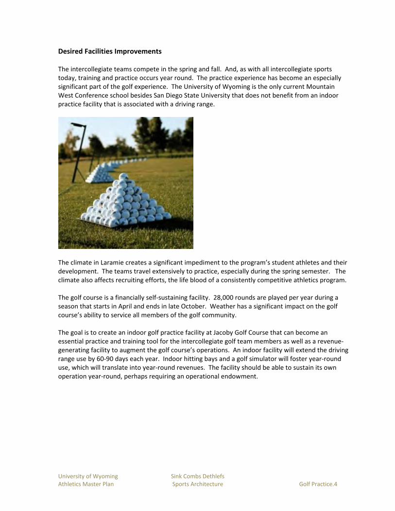
University of Wyoming Sink Combs Dethlefs
Athletics Master Plan Sports Architecture Golf Practice.4
Desired Facilities Improvements
The intercollegiate teams compete in the spring and fall. And, as with all intercollegiate sports
today, training and practice occurs year round. The practice experience has become an especially
significant part of the golf experience. The University of Wyoming is the only current Mountain
West Conference school besides San Diego State University that does not benefit from an indoor
practice facility that is associated with a driving range.
The climate in Laramie creates a significant impediment to the program’s student athletes and their
development. The teams travel extensively to practice, especially during the spring semester. The
climate also affects recruiting efforts, the life blood of a consistently competitive athletics program.
The golf course is a financially self-sustaining facility. 28,000 rounds are played per year during a
season that starts in April and ends in late October. Weather has a significant impact on the golf
course’s ability to service all members of the golf community.
The goal is to create an indoor golf practice facility at Jacoby Golf Course that can become an
essential practice and training tool for the intercollegiate golf team members as well as a revenue-
generating facility to augment the golf course’s operations. An indoor facility will extend the driving
range use by 60-90 days each year. Indoor hitting bays and a golf simulator will foster year-round
use, which will translate into year-round revenues. The facility should be able to sustain its own
operation year-round, perhaps requiring an operational endowment.

University of Wyoming Sink Combs Dethlefs
Athletics Master Plan Sports Architecture Golf Practice.5
Overview of the Facility Program
The program is centered around a large multi-purpose practice space that includes 4-5 hitting bays
that can function as either indoor netted bays or driving range tees plus a large putting surface that
can accommodate chipping as well. Each hitting bay should be set up for a video analysis system.
An outdoor synthetic chipping green surface should be located adjacent to the hitting bays. A
single bay golf simulator completes the practice/analysis components.
Support facilities include a team room with seating, TV’s, a computer station and a small counter for
food service. The team room should be directly adjacent to the practice area and may be used for
some booster or community hospitality events. A small bag storage room for the teams should be
adjacent as should a restroom for each gender. An office should be provided for the head coach
and one assistant coach. Within the building should be a hall of fame display area. If possible, a
club repair station should be incorporated.
A small storage room should be located adjacent to the indoor practice area, with a range ball
dispensing machine located directly outside under cover.
The full program is outlined on the following spreadsheet.
Proposed Indoor Golf Practice Facility Program
Competition/Practice Venue GSF
Indoor Practice Facility 1,780
Simulator 250
Support Facilities
Team Room 510
Bag Locker 200
Office 130
Restrooms 130
Range Ball Storage 70
Vestbule 200
Mech/Storage 180
Total 3,450

University of Wyoming Sink Combs Dethlefs
Athletics Master Plan Sports Architecture Golf Practice.6
The Master Plan Vision
The new facility will be located west of and adjacent to the existing driving range tee boxes. The
facility will be oriented to the centerline of the driving range. The tee box for the tenth hole will be
relocated to facilitate the proposed location. The cart paths will also require relocation, with a cart
parking/turnaround area located between the building and the driving range tees.
The main entry to the building is located so that it is visible from the clubhouse. A secondary entry
is located near the cart turnaround and provides direct access into the indoor practice facility.

University of Wyoming Sink Combs Dethlefs
Athletics Master Plan Sports Architecture Golf Practice.7
Inside the facility, the two offices will control access into the building. The entry corridor will lead
directly to the team room and will host the Hall of Fame display area. The team locker spaces and
men’s and women’s restrooms will bracket the team room. Direct access will be available from the
indoor practice space to the team rooms and the restrooms.
The storage room and the simulator will flank the indoor practice space. Large garage doors will
open onto the practice chipping green and the driving range beyond.
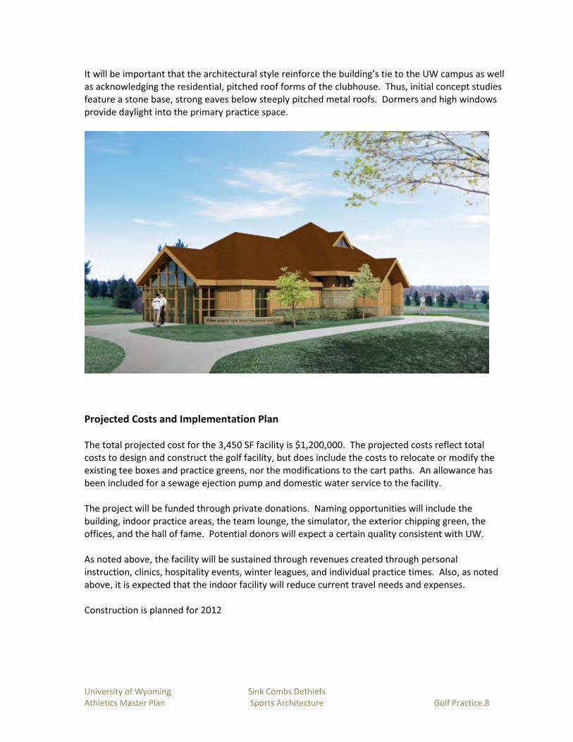
University of Wyoming Sink Combs Dethlefs
Athletics Master Plan Sports Architecture Golf Practice.8
It will be important that the architectural style reinforce the building’s tie to the UW campus as well
as acknowledging the residential, pitched roof forms of the clubhouse. Thus, initial concept studies
feature a stone base, strong eaves below steeply pitched metal roofs. Dormers and high windows
provide daylight into the primary practice space.
Projected Costs and Implementation Plan
The total projected cost for the 3,450 SF facility is $1,200,000. The projected costs reflect total
costs to design and construct the golf facility, but does include the costs to relocate or modify the
existing tee boxes and practice greens, nor the modifications to the cart paths. An allowance has
been included for a sewage ejection pump and domestic water service to the facility.
The project will be funded through private donations. Naming opportunities will include the
building, indoor practice areas, the team lounge, the simulator, the exterior chipping green, the
offices, and the hall of fame. Potential donors will expect a certain quality consistent with UW.
As noted above, the facility will be sustained through revenues created through personal
instruction, clinics, hospitality events, winter leagues, and individual practice times. Also, as noted
above, it is expected that the indoor facility will reduce current travel needs and expenses.
Construction is planned for 2012

Master Planning for the Arena-Auditorium
University of Wyoming
FINAL March 28, 2012

University of Wyoming Sink Combs Dethlefs
Athletics Master Plan Sports Architecture Arena Auditorium.1
Programs to be Served
The Arena-Auditorium (AA) is a multi-faceted building. The primary programs and events it serves
are:
• Men’s Basketball
• Women’s Basketball
• Special events (concerts, commencements, etc.)
• Off-season camps and clinics
The AA must serve the basketball programs in whole. Thus, it must function as a competition
venue, a practice venue, host to strength and conditioning and training services for the student-
athletes, offices for the coaches, and home team and visiting team locker rooms.
Each Basketball program includes approximately fifteen student-athletes. The coaching staff for
each program includes the head coach and three assistant coaches. In addition, each program has
additional support staff (e.g. Director of Operations, Director of Player Development, etc.). Each
member of the staff is a full time employee.

University of Wyoming Sink Combs Dethlefs
Athletics Master Plan Sports Architecture Arena Auditorium.2
Supporting programs that are also housed within the Arena-Auditorium (AA) include:
• Women’s Soccer—the program includes 26 student-athletes.
• Strength and Conditioning (S&C)—the Basketball programs’ student-athletes are
the primary constituents served within the Arena-Auditorium. However, with
meaningful improvements, the S&C program’s capabilities to serve additional
student-athletes and ease congestion at the Rochelle Athletics Center could be
improved as well. Staff includes one full-time S&C coach per program.
• Sports Medicine/Athletic Training—the Sports Medicine/Training program is also
directly focused on the Men’s and Women’s Basketball programs. Similar to S&C,
though, facilities improvements may allow Sports Medicine/Training to better serve
student-athletes whose locker rooms are located in the North Fieldhouse. Planned
staffing will include three full-time trainers plus several part-time assistants.
• Arena Operations—Arena Operations facilitates the events that occur within the
arena and can be labor intensive. Easy set-up and take-down for events are critical,
requiring good loading, sufficient storage, and easily convertible systems such as
telescopic seating, lighting, and audio-visual (A/V).
• Media & Public Relations—Media & Public Relations is most involved with the arena
for competition events. Efficient, well-planned accommodations for press/media,
broadcast facilities, and scoring/public address (PA)/video board functions are
essential.
• Concessions/Food Service—currently focused solely on events, improved food
service operations at the AA can not only benefit the arena patrons, but also
football stadium patrons. The existing commissary that serves War Memorial
Stadium is located in an undersized and poorly positioned space in the Fieldhouse.
The arena has a very small commissary area and each concession stand’s prep areas
are undersized, limiting menu options and the potential efficiencies of the food
service operations. Concession sales represent a potential opportunity to increase
revenues for the program. The Department of Athletics does not have a centralized
training table (dining facility) for its student-athletes. Given the importance of
nutrition and the development of community among student-athletes, a training
table function could prove highly valuable. Another potential revenue stream could
be developed through the rental of the training table space for community events
or its use as a hospitality venue before, during, or after games.
• Ticket Office—the Ticket Office serves the arena patrons, particularly for event-day
ticket sales. Improved space, distribution, and operations can allow the ticket office
to fulfill basketball needs and more effectively assist with football game day ticket
sales.
• Cowboy Joe Club—members of the Cowboy Joe Club (i.e. boosters and donors)
should enjoy an upgraded game experience. Facility improvements are required to
create an environment on par or better than the recently completed Wildcatter
Club & Suites.
• Visiting teams and game officials—facilities specifically sized and located to
accommodate these non-University users are essential to a multi-purpose arena.

University of Wyoming Sink Combs Dethlefs
Athletics Master Plan Sports Architecture Arena Auditorium.3
Analysis of the Existing Building
The Arena Auditorium is a 15,000 seat arena constructed primarily for basketball games. The venue
occasionally hosts other events including concerts, commencements, and other assembly events.
However, due in large part to the limited Laramie market area, structural limitations of the AA
(roof), and the lack of appropriate support facilities within the arena, basketball games still
dominate the building’s event schedule.
The basketball teams also use the main court as their primary practice facility. Hence, the Arena-
Auditorium (AA) is used daily throughout the school year as both a competition and practice venue.
Seating Bowl of the Arena Auditorium looking to the North
The facility is a very straightforward assembly venue. The seating bowl is a perfect circle with a
single rake bowl section. There is little differentiation other than location within the bowl for the
15,000 seats.
The concourse is at grade level, entering the seating bowl at the mid-point. The arena floor is
approximately 25’ below grade level. Pumps remove the groundwater found at or above the level
of the arena floor. All spectator facilities are located off the concourse. Restrooms and concessions
are contained within “lean-to” structures on the outboard side of the concourse. Large earth berms
disguise this outer ring of spaces. Hall of Fame displays are consistently distributed along the
inboard wall of the concourse. A continuous band of windows provide daylight to the otherwise

University of Wyoming Sink Combs Dethlefs
Athletics Master Plan Sports Architecture Arena Auditorium.4
Spartan concourses. Entries to the concourse are evenly distributed at the northeast, southeast,
southwest, and northwest points of the building. The main ticket office is located at the northwest
entry.
The North Fieldhouse building abuts and provides access to the arena at the south side, connecting
both at the Concourse Level and at the lower Locker Level. The Locker Level is located above the
arena floor level. Two ramps provide access from this level to the arena floor. Both ramps are
steeper than allowed by the Americans with Disabilities Act. Thus, the arena floor is essentially
inaccessible by ADA standards. The locker level is essentially limited to the southwest quadrant of
the building, tying into the loading ramp at the western point of the arena.
Existing Strength & Conditioning
Center
Existing Sports Medicine Center

University of Wyoming Sink Combs Dethlefs
Athletics Master Plan Sports Architecture Arena Auditorium.5
Existing Men’s Basketball Locker
Room
Facilities located at the Locker Level include small storage areas, a media hospitality room, a
converted post-game interview room, visiting team locker rooms, officials’ locker rooms, a ticket
sales office, and the Men’s Basketball home team locker room. The Women’s Basketball home
team locker room is located within the footprint of the North Fieldhouse. The Women’s Soccer
home team locker room, a small sports medicine suite, and the Strength and Conditioning center
round out the program elements at the Locker Level. Home team players access the floor via the
south ramp. Visiting teams and loading/service functions access the floor via the west service ramp.
Some improvements have been made to the seating bowl to accommodate wheelchair seating
areas. However, the building is not in compliance with the ADA requirements, most notably due to
the lack of distribution for the seating, especially in the lower seating bowl. Likewise, the restrooms
have been modified to better accommodate disabled patrons without achieving full compliance.
The Fire Marshall limits intrusions into the concourse width due to emergency egress requirements.
A limited study by the consultant team indicates that the emergency egress is more than adequate
for the building’s occupancy. The building is not fire sprinklered, which may be cause for the Fire
Marshall’s exiting concerns.

University of Wyoming Sink Combs Dethlefs
Athletics Master Plan Sports Architecture Arena Auditorium.6
View of the Pre-engineered Wood Dome
Structure
The structural system for the arena consists of a cast-in-place concrete superstructure including the
seating risers. The dome roof structure is a pre-engineered glue-laminated wood dome structure
with limited excess structural capacity as outlined in the structural engineering report in the
appendix.
The existing mechanical system is tied into the campus infrastructure. The air handlers serving the
distribution system use steam-fed heat exchangers to heat the air. No cooling is provided in the
building. The air handlers are located below the concourse within each quadrant of the building.
Fresh air intake and exhaust air is fed through large vertical concrete shafts which are visible within
the exterior bermed areas of the building. Air is supplied high at the perimeter of the seating bowl
and by ductwork suspended from the catwalk above the arena floor. The return air locations are
generally low, near the arena floor and on the concourse. The air handlers have sufficient capacity,
but will need to be retooled as part of the renovations.
In general the existing electrical systems in the Arena Auditorium are dated but functional.
• The existing electrical system for the arena is fed from the 13,200 volt campus electrical
utility system.
• The existing service feeding the arena is adequate for the current loads, but will require a
full system replacement to accommodate the future program needs.
• The existing generator is not adequate in size to accommodate a future smoke control
system (if required).
• The existing fire alarm system does not meet current code requirements for notifications in
the bowl during events.
• The light fixtures throughout the arena utilize inefficient sources such as incandescent and
are often located in areas which are difficult to maintain.
• The existing arena event lighting and control system are not adequate for adjusting the
lighting during events.

University of Wyoming Sink Combs Dethlefs
Athletics Master Plan Sports Architecture Arena Auditorium.7
• The existing lighting control system for the arena does not meet current energy code
requirements nor is it adequate for the complexities required in a multipurpose venue such
as the Arena Auditorium.
The scoreboard/video board system is outdated and in need of replacement. The current
configuration features only one video board, which means that the board is not easily viewable by
roughly one-third of the seats. Those seats must rely on two small, simple scoreboards located on
the retaining wall near the court. The system is not linked to monitors in the concourse or other
spectator-oriented areas, a typical feature of today’s arenas.
The sound system was replaced in the early 2000’s. The primary issue with the sound system is
poor distribution and intelligibility throughout the seating bowl. The sound system is linked to
other spectator-oriented spaces within the arena.
Broadcasting infrastructure has been developed over time, using spaces that are not necessarily
sized or located appropriately. Cabling for the satellite trucks occurs through the west service dock
area.

University of Wyoming Sink Combs Dethlefs
Athletics Master Plan Sports Architecture Arena Auditorium.8
Proposed Facilities Improvements
While the list of primary programs served seems modest, the lengthy list of support services
demonstrates the range of facility requirements needed to accommodate the core programs. A
modern day multi-purpose arena is a sophisticated building type that must cater to the needs of the
program users, the spectators, the operators (including the concessionaire), and radio and TV
broadcast needs, which continue to advance in terms of sophistication and desired flexibility.
Recent Transformation of The Pit, University of New Mexico’s Famed Arena
Recent or planned transformations to similar buildings, particularly in the Mountain West region,
are setting a new standard for competition and practice venues. The scope and quality of
improvements range from the very modest Moby Arena Renovations planned at Colorado State
University to the significant renovations and expansions of The Pit at the University of New Mexico.
The proposed improvements to the Arena-Auditorium are squarely in the mid-range of
improvements to other facilities and are long overdue.

University of Wyoming Sink Combs Dethlefs
Athletics Master Plan Sports Architecture Arena Auditorium.9
Team Areas
The intercollegiate basketball teams compete in the fall and winter. Training and practice activities,
however, have evolved into a year-round regimen. An additional facet of the AA’s facility
requirements is its ability to function also as the primary practice facility for the Men’s and
Women’s Basketball programs. Its current single court configuration is insufficient to accommodate
the range of drills and practice techniques required for competitive success. The goal of the master
plan is to convert portions of the lower seating bowl to telescopic seating to allow expansion of the
floor surface and inherently more flexibility for practices (and camps). Other improvements,
including lighting, sound, scoreboard/video board, and acoustical/audio-visual improvements will
be essential to the desired transformation.
UNM’s Davalos Basketball Practice Facility
University of Colorado Men’s Basketball Locker Room
Augmenting the AA’s desired use as a full-fledged modern practice facility are needed
improvements to all facilities that support the success of the Men’s and Women’s Basketball
programs. An expanded, more functional Sports Medicine/Athletic Training space is required to
adequately serve the student-athletes’ broad range of daily needs as well as those for diagnosis and
rehabilitation of injuries. A new suite is envisioned that includes an open taping/treatment area
with 4-5 treatment tables, 3 taping stations, and an adjacent wet area with a warm and a cold
plunge. Supporting spaces include three private offices, a dry storage room, an ice/water room,
and two small staff locker rooms that can be shared with Strength & Conditioning staff.

University of Wyoming Sink Combs Dethlefs
Athletics Master Plan Sports Architecture Arena Auditorium.10
The Strength and Conditioning room should be directly adjacent to the Sports Medicine/Athletic
Training suite, joined by a shared rehab area with space for several cardio stations, a variety of free
weights, weight machines, and a solid wall for medicine ball work. The main room for strength and
conditioning will provide 3,000 square feet for team work-outs. The space should feature a tall
ceiling and, if possible, daylight. Support spaces within the S&C center should include one private
office, a nutrition bar, and a sizable storage room.
UNM’s Sports Medicine Center at The Pit
University of Northern Colorado Strength & Conditioning Center
It is critical that the Strength and Conditioning and Sports Medicine/Athletic Training functions be
located at the same level as and within a short distance to the home team locker rooms.
A central equipment/laundry space and a shared film room should also be located for easy
convenience to the home team locker rooms. The equipment function can also address needs for
other teams located in the North Fieldhouse, primarily Women’s Volleyball, Wrestling, and
potentially Women’s Soccer.

University of Wyoming Sink Combs Dethlefs
Athletics Master Plan Sports Architecture Arena Auditorium.11
The home team locker room spaces must be comparable in size and amenity to fulfill Title IX
requirements. The current Men’s Basketball locker room suite provides a good model and features
a locker/dressing area, showers/toilets, a players’ lounge area, and team meeting space. Its
location at the top of the player access ramp is ideal. The coaches’ locker rooms should be located
near to the team’s locker suite. The players’ lounge spaces can be accessed separately and will be
used for small hospitality gatherings associated with events.
Academic Support services are envisioned to remain at the RAC, thus no space has been allocated in
the AA.

University of Wyoming Sink Combs Dethlefs
Athletics Master Plan Sports Architecture Arena Auditorium.12
Spectator Areas
Generally speaking, the current spectator areas, particularly the seating bowl, are adequately sized
or oversized. The objective of the planned improvements is more about quality, versatility, and
greater revenue generation.
The existing seating bowl is a circular configuration with access via vomitories that enter mid-bowl.
All seats are fixed chairback seats. ADA access, while recently improved, is limited to the concourse
level seating zones. No accessible route exists for wheelchair-bound spectators to access the
premium floor seating. At 15,000 seats, the venue has proven to have an excess of capacity. A
smaller seating capacity of 10,000 to 12,500 seats is sufficient, which could allow existing space
within the seating bowl to be captured for other uses, predominantly revenue-generating specialty
seating areas.
All seats should also be upgraded to wider seats, 20-21” in lieu of the industry standard 19” wide
seats. A minimum of approximately five hundred seats should be further upgraded to padded seats
to create a new club seating amenity. These seats should be premium, located close to and
centered on the competition court. Exclusive access to these seats should also be provided. ADA-
compliant access will also be essential.
As part of the seating bowl improvements, seating areas for the media and the band can be located
further away from the floor to devote the best seats to spectators.
Save Mart Center, Fresno State University
Within the seating bowl, other improvements are needed. New scoreboards and video boards are
essential, as is an improved sound system, and better, more flexible lighting. High definition video
boards should be installed in either a center-hung configuration or as a series of two or four boards
placed in the upper reaches of the seating bowl similar to the current video board. Ribbon boards,

University of Wyoming Sink Combs Dethlefs
Athletics Master Plan Sports Architecture Arena Auditorium.13
which will add to the dynamics of the spectator experience and can be a great revenue source are
also included within the master plan concept.
New Lobby at The Pit
New Concourse at The Pit
Outside the seating bowl, opportunities abound to improve the spectator experience. The
concourse is wide enough to handle circulation, but it is consistently dull and uninviting. Adding
graphics, better lighting and creating landmarks and wayfinding will give the concourse a livelier and
more user-friendly personality. And the hall of fame displays, which are currently underwhelming
as part of the concourse, should be moved to a dedicated space that can better glorify the past
accomplishments of the University and its student-athletes and coaches.
The entry sequence into the Arena-Auditorium can also be greatly improved. The current
configuration of four equally prominent entry points is not reflective of the parking distribution and
related circulation paths to the building. Similarly, the ticketing function is located directly opposite
its ideal placement where it can serve both AA and War Memorial Stadium events. By creating new,
prominent lobby spaces and a ticket office on the east side of the building, the entries will be better
associated with parking and can better focus the AA as a part of the Athletics complex of facilities
centered around the famous statue of “Steamboat.”

University of Wyoming Sink Combs Dethlefs
Athletics Master Plan Sports Architecture Arena Auditorium.14
Restrooms and concession stands can also be improved immensely. Fixture counts for restrooms
must be increased to meet today’s standards and provide appropriate parity between men’s and
women’s restrooms. Accessibility must also be improved. Concession stands will benefit from
better space configurations, creating appropriate food prep and sales spaces. Locating concessions
stands such that queuing does not interfere with concourse circulation will also be a significant
benefit. Portable food carts provide opportunities to increase sales points and variety of menu
offerings while allowing the number of sales points to be customized to match the anticipated
crowd size. And creating at least one or two concession spaces that can prepare grilled foods will
add to the revenue-generating capabilities of the AA.
Revenues can also be increased by adding a team store function on the east side of the building,
working, like the ticket office, equally well for AA and stadium events. Exterior access may allow
the team store to operate outside of A-A hours.
Event Support Facilities
Events cannot function efficiently without well-conceived support facilities. The desired
improvements include significant expansion of storage areas with easy access from the arena floor.
The storage will better handle portable basketball backstops, portable floor covering, and portable
staging. It is important to move these storage functions to a location that doesn’t require
negotiation of a steep ramp.
The desired quality and variety of food service for the AA requires the development of a full
concessions commissary to store and prepare food associated with events or the training table
function. A well-placed commissary could also serve the stadium.
With the conference television agreement, a significant number of athletic events will be televised
or recorded. High definition broadcasts are also redefining the support facility requirements for TV.
A new control room must be included to provide control for the video boards. Dedicated cable runs
must be developed to connect the satellite link-up trucks with the camera positions in the arena.
And flexible camera positioning must be included to maximize the capabilities of the AA to act as a
premier basketball practice facility. Equally important from an internal perspective is the ability to
film practices. Making this process easy for the Cowboys and Cowgirls would improve game
planning efficiencies.
Officials’ locker rooms, visiting team locker rooms, security/first aid rooms, and custodial areas
need to be included within the planned improvements.
The full program is outlined on the following spreadsheet.

University of Wyoming Sink Combs Dethlefs
Athletics Master Plan Sports Architecture Arena Auditorium.15

University of Wyoming Sink Combs Dethlefs
Athletics Master Plan Sports Architecture Arena Auditorium.16

University of Wyoming Sink Combs Dethlefs
Athletics Master Plan Sports Architecture Arena Auditorium.17
Proposed Building System Improvements
A complete, functional mechanical system will serve the arena renovation. The system shall be
reliable and constructed of quality, commercial grade equipment throughout to meet the state and
local codes. The systems will be designed to take advantage of the latest technology to be energy
efficient and easily maintainable while meeting the requirements of the project budget. Specific
challenges within the mechanical and plumbing systems include but are not limited to the following:
• LEED Silver or equivalent rating may be required
• Update the building automation systems to the Campus Wide Johnson Control system,
interface and monitor system remotely
• Building energy use will be monitored and displayed to demonstrate energy efficiency
features of the building
• Update the existing HVAC systems to maximize potential energy efficiency
• New systems shall take advantage of dry climate and utilize evaporative cooling
• Project shall provide comfort cooling, without the need for chilled water
• New low flow plumbing fixtures will reduce the water consumption of the facility by 30%+
over LEED baseline
A complete, functional electrical system will serve the arena renovation. The system shall be
reliable and constructed of quality, commercial grade equipment throughout to meet the state and
local codes. The systems will be designed to take advantage of the latest technology to be energy
efficient and easily maintainable while meeting the requirements of the project budget. Specific
challenges within the electrical and technology systems include but are not limited to the following:
• LEED Silver or equivalent rating may be required
• Meeting with the University to determine the necessary requirements to feed new service
entrance equipment, transformers, etc.
• Updating the power distribution to feed new scoreboards and ribbon boards.
• Updating the power distribution to feed concession loads.
• Updating the power distribution to feed broadcast equipment – including truck
connections, head-in and camera positions.
• Updating the existing lighting of the interior spaces including concourses, concessions,
restrooms, etc. Options include high efficiency LED, metal halide and compact fluorescent
lighting. Daylighting solutions will be implemented where feasible. There is currently
daylight available in the bowl which can be utilized to minimize artificial lighting for
maintenance and everyday access.
• Updating the existing egress life safety concerns within the facility. A new fire alarm and
smoke control system will likely be provided. A new generator may be required to feed all
life safety and standby loads within the arena – including egress lighting, smoke control
system, elevator(s), ribbon boards, etc. Coordination with the University will be required to
determine if the existing generator should be augmented, replaced or relocated to another
building on campus.

University of Wyoming Sink Combs Dethlefs
Athletics Master Plan Sports Architecture Arena Auditorium.18
• Updating the event lighting for high definition broadcasts with new high efficiency
shuttered sports lights. High efficiency fixtures will be utilized to limit the load on the
existing structure.
• Updating the event lighting to include multipurpose scenes for commencement, concerts,
theatrical events, etc.
• Updating the technology systems to support new point of sale, telephone and data
requirements. Options include new fiber and copper systems to support both wired and
wireless technology.
• Explore a potential distributed antenna system (DAS) within the arena to support today’s
and future cellular content as a revenue generating element.
Refer to the appendix for additional information.

University of Wyoming Sink Combs Dethlefs
Athletics Master Plan Sports Architecture Arena Auditorium.19
The Master Plan Vision
Site Plan
To fulfill the programmatic requirements, space must be added to the Arena-Auditorium. The
master plan does so on the east and southeast sides of the arena. As the University’s athletics
facilities have developed, the “center of gravity” for athletics facilities has become the circular entry
drive that is framed by North Fieldhouse to the west, the west stands of War Memorial Stadium to
the south, and the Rochelle Athletics Center to the east. It is logical that the Arena-Auditorium’s
expansion and improvements reinforce this evolution.

University of Wyoming Sink Combs Dethlefs
Athletics Master Plan Sports Architecture Arena Auditorium.20
Long range view from the east
Approach to the proposed new Northeast Entry
One of two new lobbies

University of Wyoming Sink Combs Dethlefs
Athletics Master Plan Sports Architecture Arena Auditorium.21
Building Additions
The vision develops an emphasis on entry into the east side of the AA. By creating a new concourse
on the eastern perimeter of the building, several opportunities are created:
• The outboard concourse can employ a transparent glass wall that makes for a much
friendlier concourse experience and showcases the activity within the building to those who
pass by or approach
• Expanded entries at the southeast and northeast can create a much stronger entry
sequence and identifiable imagery
• The existing concourse space can be captured to fulfill the programmatic requirements for a
dedicated club space which can also expand into the seating bowl and serve the new club
seats near the arena floor
• A new Hall of Fame space can be created that can function as a pre-function space for the
new club, or, in association with the new concourse space, can become an independent
hospitality space
Equally beneficial is a similar building expansion that occurs between the southeast entry expansion
and the existing North Fieldhouse building. Although the footprint of the expansion at this location
is comparatively small, the advantage is the creation of a service zone that features a vertical link
that can serve five different levels, including the arena floor level. To complete this link, the master
plan proposes the construction of a tunnel connection from the lowest level of the new addition to
reach the arena floor. The tunnel, in combination with a new large elevator, will provide access to
the arena floor and its seating areas for disabled patrons, addressing the most glaring ADA
deficiency of the existing building. A large storage area, media room, and public restrooms, also
located within the addition’s footprint, fulfill very important programmatic needs associated with
the arena floor. The sections below describe the vertical relationships of spaces and the improved
access to the arena floor.

University of Wyoming Sink Combs Dethlefs
Athletics Master Plan Sports Architecture Arena Auditorium.22

University of Wyoming Sink Combs Dethlefs
Athletics Master Plan Sports Architecture Arena Auditorium.23
Arena floor being used for practice
The planned renovations will transform the seating bowl into a vibrant practice and competition
venue. Expanding the floor will allow the arena floor to accommodate full team practices.
A gameday view of the revitalized seating bowl

University of Wyoming Sink Combs Dethlefs
Athletics Master Plan Sports Architecture Arena Auditorium.24
Seating replacement, new video boards, ribbon boards, lighting, and sound system upgrades will
transform the character of the seating bowl.
Added storage, restrooms, a media room, and the new tunnel/elevator connection will enhance the
versatility of the building and help to place fan amenities where needed. Disabled fans, in
particular, will benefit from the improvements, as will the media and VIP patrons.

University of Wyoming Sink Combs Dethlefs
Athletics Master Plan Sports Architecture Arena Auditorium.25
At the locker room level, all spaces will be improved The Women’s Basketball locker room will be
renovated and expanded to match the Men’s Locker Room in size and quality. The existing Sports
Medicine space will be renovated and expanded. Strength and Conditioning will be moved into the
space currently dedicated to visiting team locker rooms. The new space will be larger than the
current space and will feature a direct, shared rehabilitation room link to Sports Medicine. New
visiting team locker rooms will be created within the footprint of the existing weight room and
officials’ locker room.

University of Wyoming Sink Combs Dethlefs
Athletics Master Plan Sports Architecture Arena Auditorium.26
At the concourse level, the expansion includes a new concessions commissary with direct access
into a small service court. On the concourse side of the commissary, a new, full service concession
stand will benefit from the direct adjacency. The new ticket office space is also located at this level,
adjacent to the southeast entry, creating an indoor lobby space that will work very effectively, both
on game-days and during regular business hours for the ticket office.
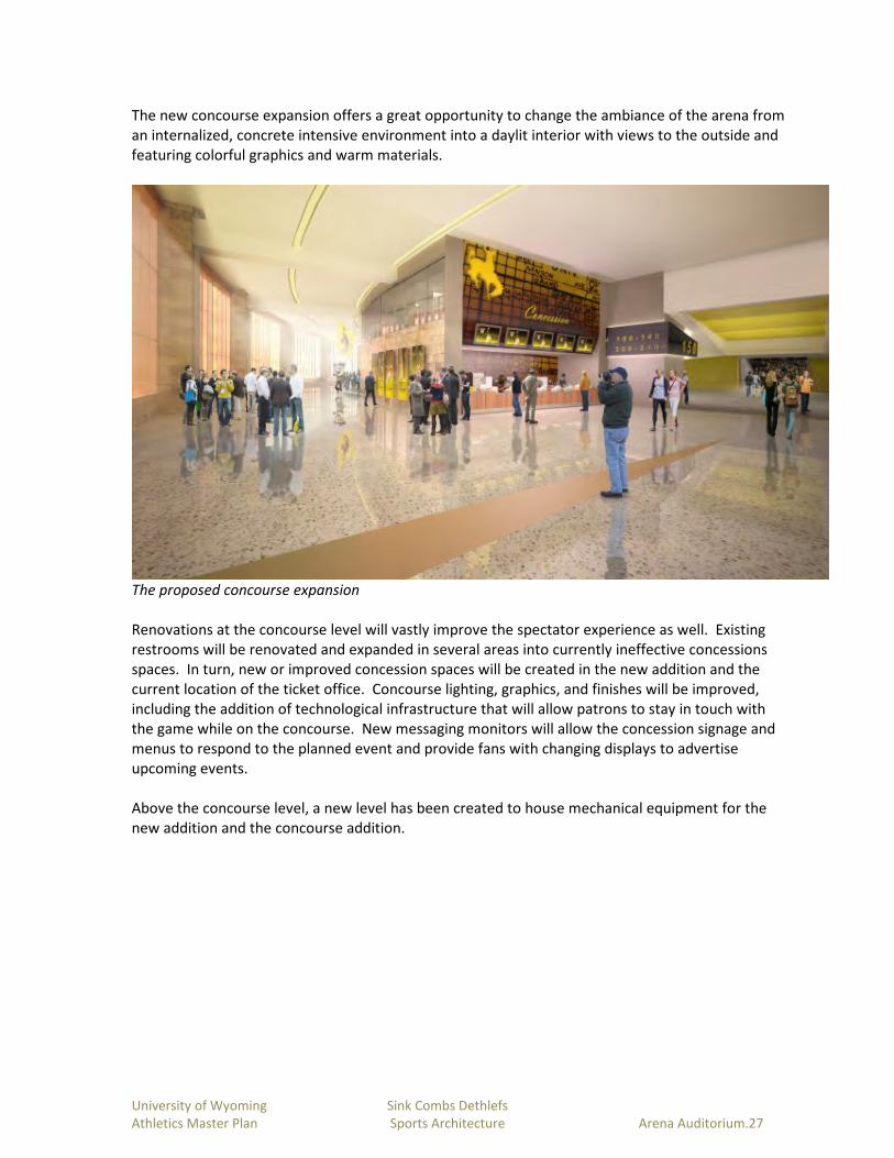
University of Wyoming Sink Combs Dethlefs
Athletics Master Plan Sports Architecture Arena Auditorium.27
The new concourse expansion offers a great opportunity to change the ambiance of the arena from
an internalized, concrete intensive environment into a daylit interior with views to the outside and
featuring colorful graphics and warm materials.
The proposed concourse expansion
Renovations at the concourse level will vastly improve the spectator experience as well. Existing
restrooms will be renovated and expanded in several areas into currently ineffective concessions
spaces. In turn, new or improved concession spaces will be created in the new addition and the
current location of the ticket office. Concourse lighting, graphics, and finishes will be improved,
including the addition of technological infrastructure that will allow patrons to stay in touch with
the game while on the concourse. New messaging monitors will allow the concession signage and
menus to respond to the planned event and provide fans with changing displays to advertise
upcoming events.
Above the concourse level, a new level has been created to house mechanical equipment for the
new addition and the concourse addition.

University of Wyoming Sink Combs Dethlefs
Athletics Master Plan Sports Architecture Arena Auditorium.28
Entry into the new Club
The east side of the seating bowl, including the associated concourse spaces will undergo significant
renovation to create a new club room with dedicated amenities and the requisite proximity to the
converted club seating sections and the playing floor. The club environment will combine great
views to the floor as well as a flexible, well appointed multi-use space that can become a
complement to the rental opportunities now available in the Wildcatter Club & Suites at War
Memorial Stadium.
The orientation of the club requires that the competition floor be rotated 90 degrees from its
current orientation. This is made possible by the expansion of the competition floor by removing
the existing ramps and retaining walls that bound the floor. Some lower seating rows will be
removed and new retaining walls will be created to expand the floor surface. The floor will also be
raised to meet the bottom of the player’s ramp as it emerges from the vomitory. New telescopic
seating sections will enable the quick conversion form practice facility to competition venue.

University of Wyoming Sink Combs Dethlefs
Athletics Master Plan Sports Architecture Arena Auditorium.29
As noted above, the addition of a new tunnel under the seating bowl will connect the floor to the
new elevator in the southern portion of the addition.
The proposed renovations will transform the arena into a great competition venue and a highly
functional basketball practice facility. The renovations will also transform the concourse into a
functional and dynamic spectator environment with easy access to restrooms, food service, and the
Hall of Fame. And renovations will convert current spaces that are poor matches to their current
use into spaces that are appropriately used and located relative to other functions.

University of Wyoming Sink Combs Dethlefs
Athletics Master Plan Sports Architecture Arena Auditorium.30
Projected Costs and Implementation Plan
The project will likely be phased. The master plan concept illustrates a two phase plan.
Phase 1
The attached diagram illustrates the prosed Phase 1 scope of work, which in summary includes:
• Expand court size (more floor space for coaches to use for practices), re-orient and replace
AA basketball floor.
• Reconfigure lower seating bowl to include new club seating area for 500+ spectators as well
as dedicated media, band and student sections.
• Upgrade lighting (more current/efficient technology that provides better venue coverage
and allows lights to be dimmed or “shuttered” for more dynamic pre-game/event
introductions and special effects)
• New video scoreboards/LED ribbon boards (two video boards on opposite ends of main
court and LED ribbon boards under club seating area)
• New sound system (new speakers and amplifier arrays) that allows more effective coverage
of both lower and upper seating areas. This would be used for sporting events,
commencements, and special events.
• Renovate the majority of the current Locker Room Level to create enhanced Sports
Medicine, Strength and Conditioning, visiting team/officials locker rooms, post-game
interview room, etc.
• Upgrade and enhance men’s and women’s locker rooms/team rooms

University of Wyoming Sink Combs Dethlefs
Athletics Master Plan Sports Architecture Arena Auditorium.31
The total project costs (including construction and non-construction costs) for Phase 1 could range
from $8.25 million to $9.5 million. The projected costs do not include any allowances for inflation.
The Phase 1 project will be funded through a combination of State funds and private donations.
Primary naming opportunities will include the arena, the video boards, the renovated locker rooms
and training areas, and the court.
Phase 2
The Phase 2 scope of work focuses primarily on technology and seating upgrades to the seating
bowl. Proposed work includes:
• Develop entire east side (facing RAC) as the major facade of the facility including two new
Entry lobbies.
• Create an entire new look for the concourse area including all concession areas (fewer, but
more points of sale), merchandise areas, restrooms, way finding, etc.
• Create a new, central Ticket Office to serve the A-A and War Memorial Stadium.
• Create a Hall of Fame and Club area at the east concourse.
• Develop a concession commissary within the southeast portion of the addition that will
serve the A-A, War Memiorial Stadium and other Athletics events.

University of Wyoming Sink Combs Dethlefs
Athletics Master Plan Sports Architecture Arena Auditorium.32
• Include an elevator that that will improve access for patrons (including disabled patrons)
seated on or near the arena floor.
• Build a tunnel connection, restrooms, media room, and new storage areas to connect the
elevator to the arena floor area.
The total project costs for Phase 2 could range from $21 million to $24 million. The projected costs
do not include any allowances for inflation.
The Phase 2 project will be funded through a combination of State funds and private donations.
Primary naming or sponsorship opportunities will include two new entry lobbies, the Hall of Fame,
the Club, the tunnel in combination with the club seating, and the concourse improvements.

Master Planning for Corbett Pool
University of Wyoming
FINAL March 28, 2012

University of Wyoming Sink Combs Dethlefs
Athletics Master Plan Sports Architecture Corbett Pool.1
Programs to be Served
The University of Wyoming swimming and diving program aspires to be ranked nationally as a
top 25 program. For the current 23 male and 35 female student-athletes, the existing Corbett
Pool facility is inadequate to accomplish that goal. With a competitive facility, the University
expects to increase the programs to 30 males and 45 females and excel at both recruiting and
training the best student-athletes.
The local high school swim team may also be served by the new competition pool and its
support facilities. Recreation, intramural, and club sport programs are likely users, including
program activities such as competitive swimming, water polo, inner tube water polo,
kayak/water sports instruction, and scuba or other specialized instructional or certificate
programs.
Community use will primarily be tied to either the high school or University competitions.
Opportunities will likely exist, however, for high altitude training camps as well as camps run by
the coaching staff. All of these uses offer revenue-generation opportunities to help offset the
costs of operating the pool.

University of Wyoming Sink Combs Dethlefs
Athletics Master Plan Sports Architecture Corbett Pool.2
Analysis of the Existing Facility
Existing Natatorium with View toClassroom
Glass Wall
Existing 1-meter Spring Board
The natatorium is one of several components of the Corbett complex. Academic users,
intramurals, student recreation users, community users, and student-athletes all use portions of
the building. The master plan analysis focused solely on the natatorium components of the
facility, with the recognition that any of the other facilities affected by the master plan proposal
must, at a minimum, replace or restore those facilities to their current condition.
Existing Classroom with Views beyond Curtains
to Pool

University of Wyoming Sink Combs Dethlefs
Athletics Master Plan Sports Architecture Corbett Pool.3
The existing Corbett pool facility, which was built in the mid-1970’s, lacks several facets
important to the success of the University’s student-athletes. The current pool’s size is both too
short for the student-athletes to swim the preferred length of 50 meters and too shallow for
diving over 3 meter springboard. Secondly, the water body is contiguous, which makes it
impossible for dual practice or hosting of simultaneous events.
Existing Shower Facility, Men’s Locker Room
Existing Locker Room
In terms of supporting core competition and training activities, the pool’s deck space is minimal,
the pool is supported by outdated and utilitarian locker spaces, and the lack of amenities and
enhancements limits the student-athlete’s experience. During competitions, spectators and
athletes are removed from each other by a glass partition, separating the spectators from the
action and isolating the student-athletes from the energy of the crowd.
The existing pool mechanical equipment is located in the basement below the pool deck. While
this is a reasonable use of space, periodic maintenance or replacement of the equipment is
severely hampered by difficult access to this level.

University of Wyoming Sink Combs Dethlefs
Athletics Master Plan Sports Architecture Corbett Pool.4
Potential Development Partnerships
The University of Wyoming’s goal is to raise the standard for both the current and prospective
swimming and diving student-athletes. Although the University could market the new aquatic
facility as a destination venue for high-altitude training, catering to potential outside interests is
not a priority.
An opportunity does exist, however, to partner with Laramie High School. The high school’s
existing pool offers, like Corbett, numerous challenges in operation and programming,
prompting the need to explore options for a new pool. A partnership with the high school
would fulfill an educational need in the community as well as help develop potential student-
athletes locally.
Desired Facilities Improvements
Throughout the Mountain West Conference and across the nation, 50 meter swimming and 5
meter diving are medians for competition aquatics facilities. The University of Wyoming is
poised to achieve this standard with the renovation and expansion of Corbett Pool.
The program for an updated facility is centered around the new pool, anchored by an extensive
deck which would be capable of hosting dry land training and ample staging space for meets.
Satellite coach’s offices, storage, and a wet classroom should be accessible from the deck.
Spectators will be accommodated through a bleacher seating area with a minimum capacity of
500 people. Interior clear heights within the natatorium should be a minimum of thirty feet
above the main pool body and forty feet above the diving area. Pool mechanical spaces are a
critical component of the program, requiring adequate size, access, and utility infrastructure to
support a large body of water.
New 50-meter Pool with 3-meter platform at Colorado Mesa University

University of Wyoming Sink Combs Dethlefs
Athletics Master Plan Sports Architecture Corbett Pool.5
The following program spreadsheet outlines the basic components. More detailed information,
particularly regarding the aquatics facilities, can be found in the Counsilman Hunsaker report in
the appendix.
Proposed Swimming and Diving Program
GSF Remarks
Competition/Practice Venue
50-meter Pool 26,660
Diving well
Spectator Seating
3,920
With Pool
Subtotal 30,580
Support Facilities
Lobby
Control/Office
1,175
220
Lifeguard 245
Wet classroom 810
Pool Storage 615
Pool Mechanical 3,340
Dry Land Training
Coaches Offices
0
480
On pool deck
(4) at 120 sf each
Team Meeting 825
Video Room 470
Sports Medicine 1,260
Men’s Varsity Locker Room
900
Men’s Coaches Locker Room
Women’s Varsity Locker Room
180
1,000
Women’s Coaches Locker Room 180
Men’s General Use Locker Room 3,515 Wet and Dry Use
Women’s General Use Locker room 5,490 Wet and Dry Use
Vis Coach/Family Change Rooms 400 (2) at 200 sf each
Misc/RR/Circulation New 8,800
Subtotal 30,240
60,820 New and Renovated
Program Space
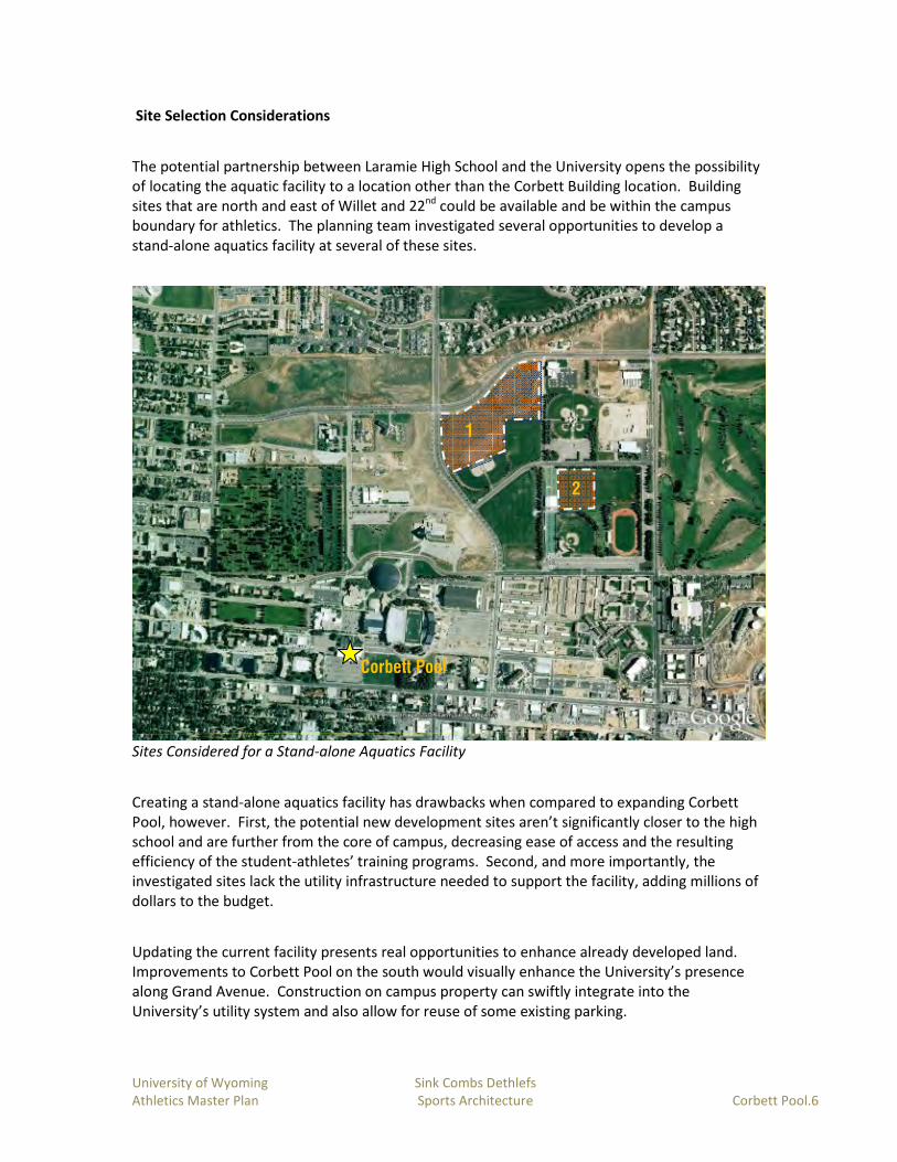
University of Wyoming Sink Combs Dethlefs
Athletics Master Plan Sports Architecture Corbett Pool.6
Site Selection Considerations
The potential partnership between Laramie High School and the University opens the possibility
of locating the aquatic facility to a location other than the Corbett Building location. Building
sites that are north and east of Willet and 22nd could be available and be within the campus
boundary for athletics. The planning team investigated several opportunities to develop a
stand-alone aquatics facility at several of these sites.
Sites Considered for a Stand-alone Aquatics Facility
Creating a stand-alone aquatics facility has drawbacks when compared to expanding Corbett
Pool, however. First, the potential new development sites aren’t significantly closer to the high
school and are further from the core of campus, decreasing ease of access and the resulting
efficiency of the student-athletes’ training programs. Second, and more importantly, the
investigated sites lack the utility infrastructure needed to support the facility, adding millions of
dollars to the budget.
Updating the current facility presents real opportunities to enhance already developed land.
Improvements to Corbett Pool on the south would visually enhance the University’s presence
along Grand Avenue. Construction on campus property can swiftly integrate into the
University’s utility system and also allow for reuse of some existing parking.
Corbett Pool
1
2

University of Wyoming Sink Combs Dethlefs
Athletics Master Plan Sports Architecture Corbett Pool.7
Updating the current facility also maintains close proximity to necessary services and avoids
doubling up on program. Student-athletes and coaches can access strength training and
academic support spaces within the Rochelle Athletics Center and offices within Fieldhouse
North. Staff can optimize efficiency by utilizing the laundry facilities at the RAC and in FHN
(Fieldhouse North).
During the master planning process, analysis included evaluations of development opportunities
on the north, east, and south sides of the existing Corbett Pool. Expansion to the north was
found to be too disruptive to the future green space and Fine Arts theater expansion that will
replace the current parking lot. Expansion to the east (including options that contained a
portion of the new pool within the existing Corbett Pool footprint) impinges on the parking lot
to the south of the Fieldhouse and on the recently completed retention pond/practice fields
project. Although expansion to the south eliminates existing parking, its visibility from Grand
Avenue, internal space relationships, and flexibility of configuration made this the preferred site
for expansion.
The Master Plan Vision
The vision anticipates that a significant addition will be designed on the south side of the
existing Corbett Pool. The location offers adequate site area and opportunities to use existing
space within Corbett Gym that can continue to function for general student use as well as
visiting team use.
By locating the new aquatics facilities outside the footprint of the natatorium, the existing pool
can remain in use while the bulk of the new construction is accomplished. Once the new pool is
constructed, the existing natatorium becomes an ideal location for support facilities. Thus,
much of the new program space will be located within the shell of the old natatorium. This will
include most of the home team space including locker rooms, team room, sports medicine and a
video room. Mechanical space for the new pool will also be located at grade within this
footprint, eliminating the need for basement access. The basement would become free for
storage or other program space. The remainder of the Corbett building would be left in its
current configuration and use.
The new natatorium will feature a ten-lane 50-meter pool with movable bulkheads to maximize
flexibility of use. One end of the pool will accommodate the dive tower and diving well. Seating
will be located on the upper level, separating spectator circulation and access from that of the
competitors. Please refer to the full narrative produced by Counsilman Hunsaker for a detailed
outline of the proposed facility requirements.
Lastly, the renovation and addition to Corbett Pool will explore and implement as many
sustainable ideas as possible with the intention of achieving Leadership in Energy and
Environmental Design (LEED) equivalent to certification. Innovations in stormwater
management, solar heating and photovoltaics as well as increased daylighting and thermal
efficiency, are just a few of the viable options available.

University of Wyoming Sink Combs Dethlefs
Athletics Master Plan Sports Architecture Corbett Pool.8

University of Wyoming Sink Combs Dethlefs
Athletics Master Plan Sports Architecture Corbett Pool.9

University of Wyoming Sink Combs Dethlefs
Athletics Master Plan Sports Architecture Corbett Pool.10
During the master planning process, the consultant team developed initial three-dimensional
massing studies to better understand the impacts of scale and placement that the facility could
have on its site and neighboring buildings. The attached renderings reflect the preferred master
plan vision, which includes the incorporation of an arced roof that reflects other campus
athletics buildings, the development of an easily identifiable and welcoming entry point, and the
potential incorporation of daylighting.
View from the Southwest
Interior Perspective Looking North

University of Wyoming Sink Combs Dethlefs
Athletics Master Plan Sports Architecture Corbett Pool.11
Projected Costs and Implementation Plan
The project will require phasing in an effort to reduce the amount of down time for pool use. By
constructing the new addition first and then renovating the existing space, pool operations will
be shut down only during the timeframe in which the existing natatorium is converted to the
pool mechanical room—a process projected to take three to six months. The overall
construction timeline could take roughly 32 months to complete with time lines as follows:
Design nine months
New construction sixteen months
Changeover of pool mechanical four months
Final renovations to Corbett three months
Total costs could to be $18,500,000 to $20,000,000. Consistent with recent funding models, the
University anticipates that funding will be derived from matching gifts to an initial commitment
of funds from the State Legislature.