atf results and atf-ii plans
TRANSCRIPT

2007/6/28 PAC07 in Albuquerque 1
ATF Results and ATF-II Plans
Junji Urakawa (KEK)for
the ATF International Collaboration
Ongoing unique test facility for ILC with a low emittance beam.
2007/6/28 PAC07 in Albuquerque 2
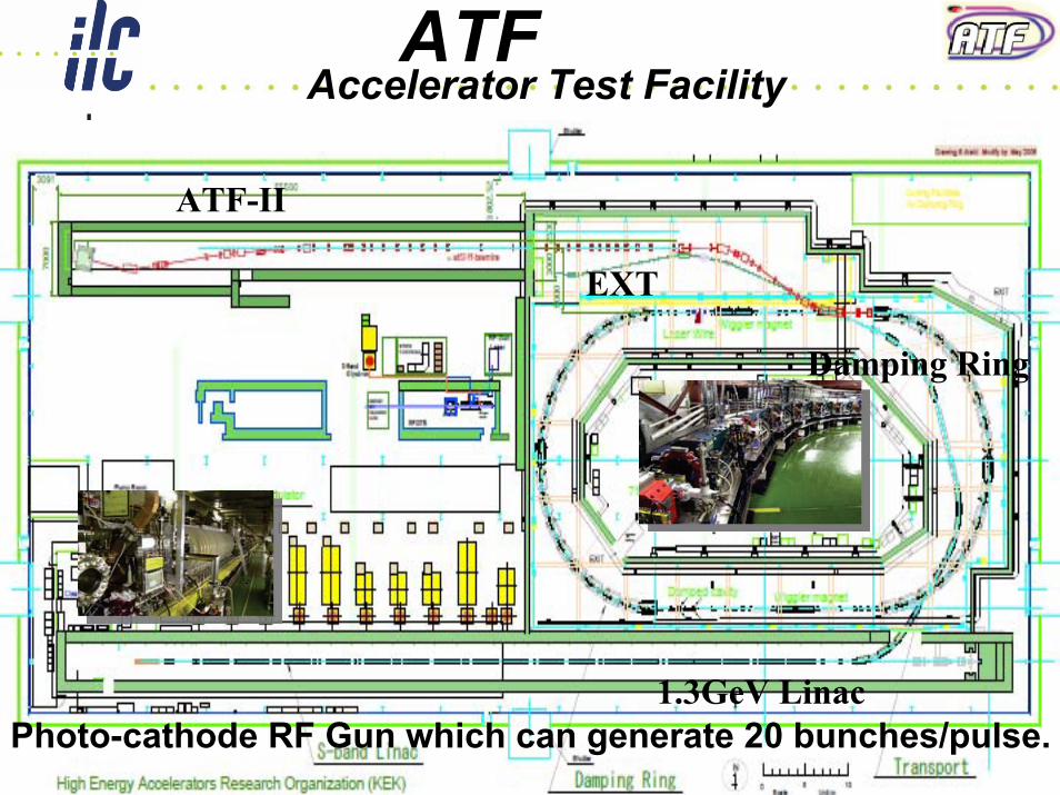
ATFAccelerator Test Facility
Photo-cathode RF Gun which can generate 20 bunches/pulse.
ATF-II
EXT
1.3GeV Linac
Damping Ring
2007/6/28 PAC07 in Albuquerque 3
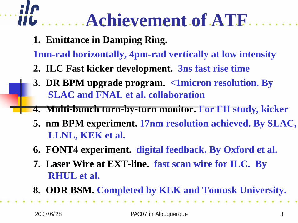
1. Emittance in Damping Ring.1nm-rad horizontally, 4pm-rad vertically at low intensity2. ILC Fast kicker development. 3ns fast rise time3. DR BPM upgrade program. <1micron resolution. By
SLAC and FNAL et al. collaboration4. Multi-bunch turn-by-turn monitor. For FII study, kicker5. nm BPM experiment. 17nm resolution achieved. By SLAC,
LLNL, KEK et al.6. FONT4 experiment. digital feedback. By Oxford et al.7. Laser Wire at EXT-line. fast scan wire for ILC. By
RHUL et al.8. ODR BSM. Completed by KEK and Tomusk University.
Achievement of ATF
2007/6/28 PAC07 in Albuquerque 4
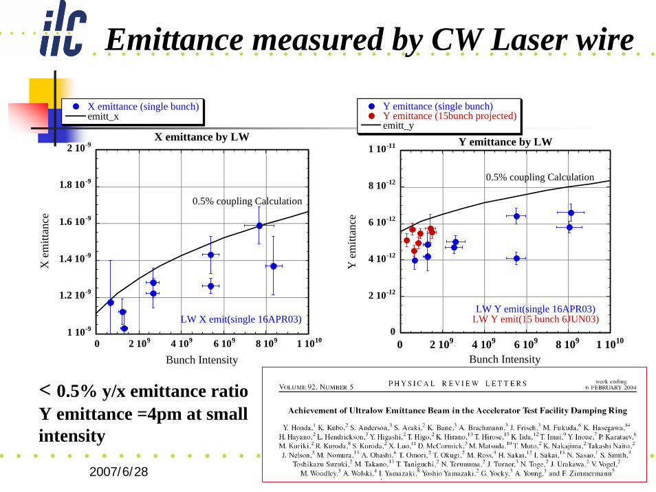
Emittance measured by CW Laser wire
< 0.5% y/x emittance ratioY emittance =4pm at small intensity
1 10-9
1.2 10-9
1.4 10-9
1.6 10-9
1.8 10-9
2 10-9
0 2 109 4 109 6 109 8 109 1 1010
X emittance by LW
X emittance (single bunch)emitt_x
X e
mitt
ance
Bunch Intensity
0.5% coupling Calculation
LW X emit(single 16APR03)0
2 10-12
4 10-12
6 10-12
8 10-12
1 10-11
0 2 109 4 109 6 109 8 109 1 1010
Y emittance by LW
Y emittance (single bunch)Y emittance (15bunch projected)emitt_y
Y e
mitt
ance
Bunch Intensity
0.5% coupling Calculation
LW Y emit(single 16APR03)LW Y emit(15 bunch 6JUN03)
2007/6/28 PAC07 in Albuquerque 5
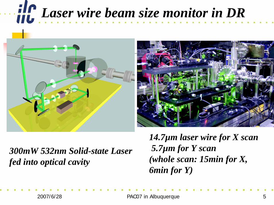
Laser wire beam size monitor in DR
14.7µm laser wire for X scan5.7µm for Y scan(whole scan: 15min for X,6min for Y)
300mW 532nm Solid-state Laserfed into optical cavity
2007/6/28 PAC07 in Albuquerque 6
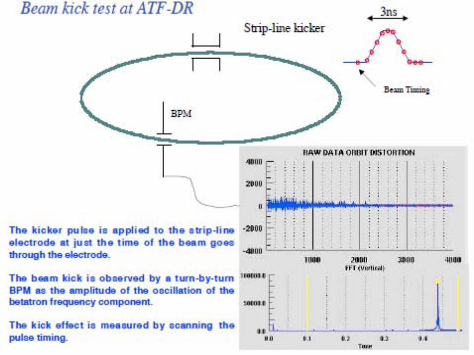
2007/6/28 PAC07 in Albuquerque 7
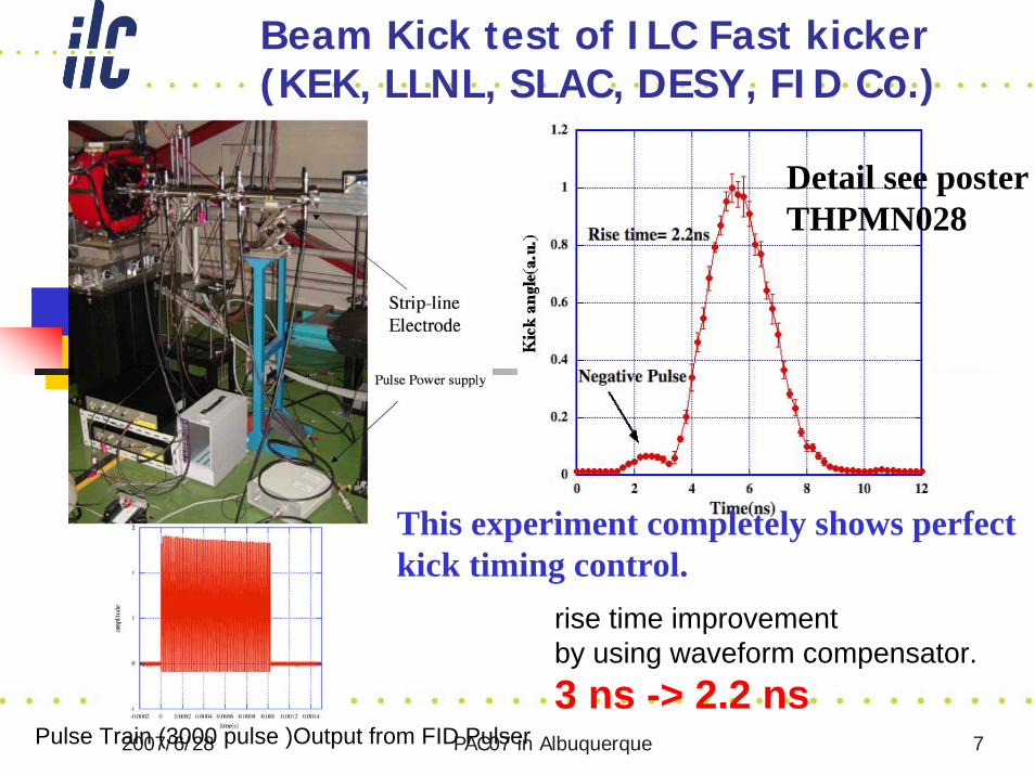
rise time improvement by using waveform compensator.3 ns -> 2.2 ns
Pulse Train (3000 pulse )Output from FID Pulser
This experiment completely shows perfectkick timing control.
Detail see posterTHPMN028
Beam Kick test of ILC Fast kicker (KEK, LLNL, SLAC, DESY, FID Co.)
2007/6/28 PAC07 in Albuquerque 8
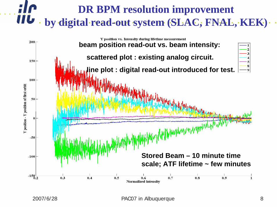
Stored Beam – 10 minute time scale; ATF lifetime ~ few minutes
beam position read-out vs. beam intensity:
scattered plot : existing analog circuit.
line plot : digital read-out introduced for test.
DR BPM resolution improvement by digital read-out system (SLAC, FNAL, KEK)
2007/6/28 PAC07 in Albuquerque 9
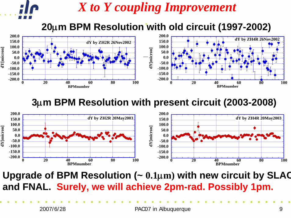
X to Y coupling Improvement
-200.0-150.0-100.0
-50.00.0
50.0100.0150.0200.0
0 20 40 60 80 100
dY by ZH2R 26Nov2002
dY[m
icro
n]
BPMnumber
-200.0-150.0-100.0
-50.00.0
50.0100.0150.0200.0
0 20 40 60 80 100
dY by ZH4R 26Nov2002
dY[m
icro
n]
BPMnumber
-200.0-150.0-100.0
-50.00.0
50.0100.0150.0200.0
0 20 40 60 80 100
dY by ZH2R 20May2003
dY[m
icro
n]
BPMnumber-200.0-150.0-100.0-50.0
0.050.0
100.0150.0200.0
0 20 40 60 80 100
dY by ZH4R 20May2003
dY[m
icro
n]
BPMnumber
3μm BPM Resolution with present circuit (2003-2008)
20μm BPM Resolution with old circuit (1997-2002)
Upgrade of BPM Resolution (~ 0.1μm) with new circuit by SLACand FNAL. Surely, we will achieve 2pm-rad. Possibly 1pm.
2007/6/28 PAC07 in Albuquerque 10
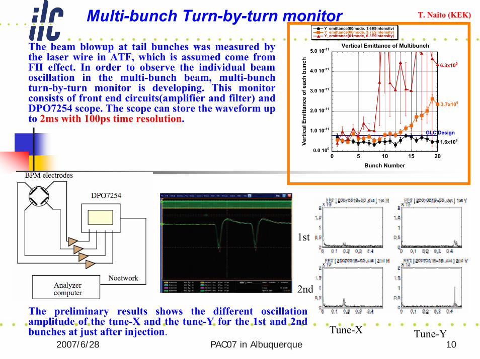
Multi-bunch Turn-by-turn monitor
The beam blowup at tail bunches was measured by the laser wire in ATF, which is assumed come from FII effect. In order to observe the individual beam oscillation in the multi-bunch beam, multi-bunch turn-by-turn monitor is developing. This monitor consists of front end circuits(amplifier and filter) and DPO7254 scope. The scope can store the waveform up to 2ms with 100ps time resolution.
T. Naito (KEK)
0.0 100
1.0 10-11
2.0 10-11
3.0 10-11
4.0 10-11
5.0 10-11
0 5 10 15 20
Vertical Emittance of Multibunch
Y_emittance(00mode, 1.6E9intensity)Y_emittance(00mode, 3.7E9intensity)Y_emittance(01mode, 6.3E9intensity)
Vert
ical
Em
ittan
ce o
f eac
h bu
nch
Bunch Number
1.6x10⁹
3.7x10⁹
6.3x10⁹
GLC Design
The preliminary results shows the different oscillation amplitude of the tune-X and the tune-Y for the 1st and 2ndbunches at just after injection. Tune-X Tune-Y
2nd
1st
2007/6/28 PAC07 in Albuquerque 11
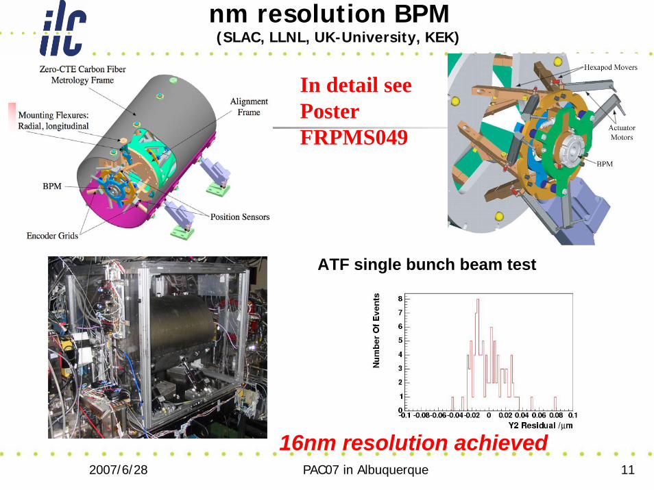
nm resolution BPM(SLAC, LLNL, UK-University, KEK)
ATF single bunch beam test
16nm resolution achieved
In detail seePoster FRPMS049
2007/6/28 PAC07 in Albuquerque 12
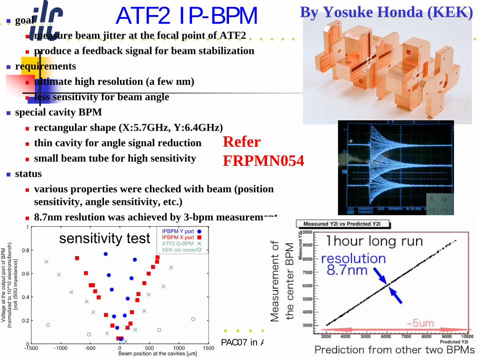
goalmeasure beam jitter at the focal point of ATF2produce a feedback signal for beam stabilization
requirements ultimate high resolution (a few nm)less sensitivity for beam angle
special cavity BPMrectangular shape (X:5.7GHz, Y:6.4GHz)thin cavity for angle signal reductionsmall beam tube for high sensitivity
statusvarious properties were checked with beam (position sensitivity, angle sensitivity, etc.)8.7nm reslution was achieved by 3-bpm measurement
ATF2 IP-BPM
sensitivity test
By Yosuke Honda (KEK)
Refer FRPMN054
2007/6/28 PAC07 in Albuquerque 13
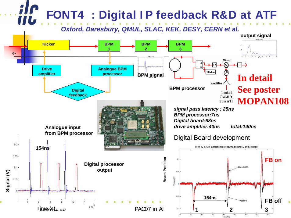
FONT4 : Digital IP feedback R&D at ATF
Digital Board development
Oxford, Daresbury, QMUL, SLAC, KEK, DESY, CERN et al.
Time (s)
Sign
al (V
)
Analogue inputfrom BPM processor
Digital processoroutput
154ns
signal pass latency : 25nsBPM processor:7nsDigital board:68nsdrive amplifier:40ns total:140ns
Kicker BPM 1
Digital feedback
Analogue BPM processor
Driveamplifier
BPM 2
BPM 3
e-
BPM processor
BPM signal
output signal
Bea
m P
ositi
on
1 2 3FB off
FB on
154ns
In detailSee posterMOPAN108
2007/6/28 PAC07 in Albuquerque 14
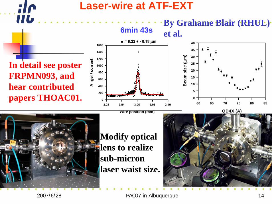
Laser-wire at ATF-EXT
6min 43s
QD4X (A)
60 65 70 75 80 85
Bea
m s
ize
( μm
)
0
5
10
15
20
25
30
35
40
By Grahame Blair (RHUL)et al.
Modify optical lens to realizesub-micronlaser waist size.
In detail see posterFRPMN093, andhear contributedpapers THOAC01.

2007/6/28 PAC07 in Albuquerque 15
Optical Diffraction Radiation (ODR) beam size monitor (BSM) at KEK-ATF
γ θx
-4 -3 -2 -1 0 1 2 3 4
γ θ y
-4
-3
-2
-1
0
1
2
3
4
Typical CCD image of ODR vertical polarization
componente-beam
ALTA E400
443mm
OTR, ODR
polarizer
optical filter
lens (f=200mm)
200mm
slit target
Experimental layout
2007/6/28 PAC07 in Albuquerque 16
γθy
-4 -2 0 2 4
Inte
nsity
(CC
D c
hann
els)
0
100
200
300
400
500h = 0.07mm
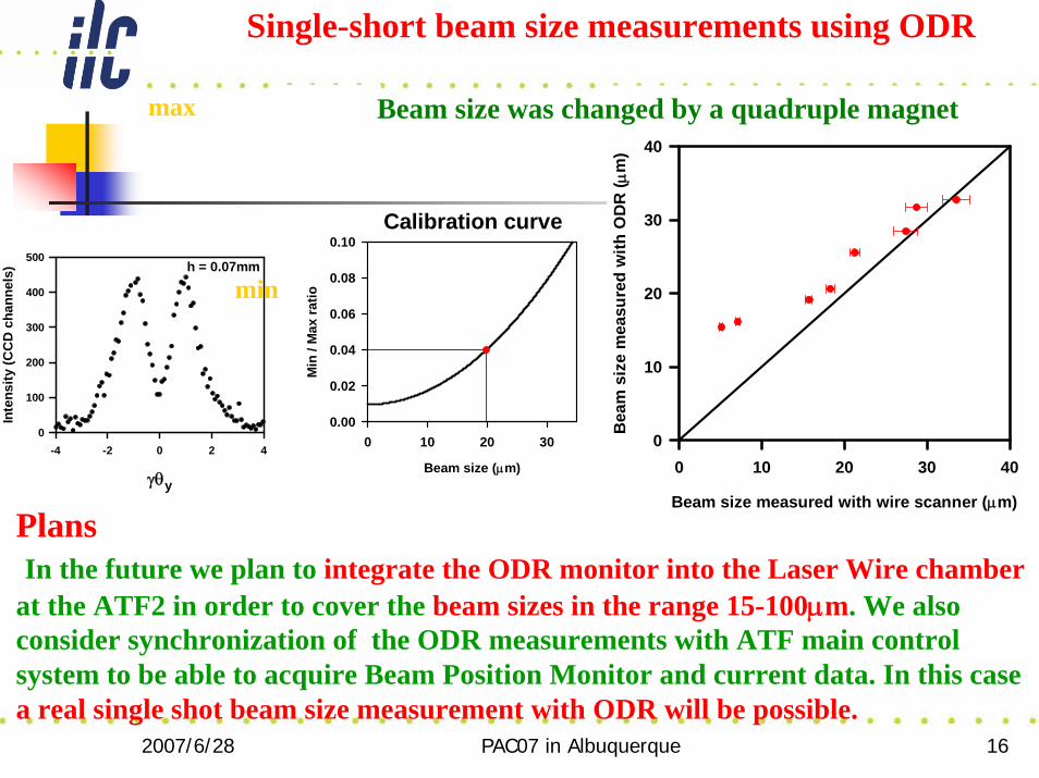
Single-short beam size measurements using ODR
Calibration curve
Beam size (μm)
0 10 20 30
Min
/ M
ax ra
tio
0.00
0.02
0.04
0.06
0.08
0.10
min
max
Beam size measured with wire scanner (μm)
0 10 20 30 40
Bea
m s
ize
mea
sure
d w
ith O
DR
( μm
)
0
10
20
30
40
Beam size was changed by a quadruple magnet
PlansIn the future we plan to integrate the ODR monitor into the Laser Wire chamber
at the ATF2 in order to cover the beam sizes in the range 15-100μm. We also consider synchronization of the ODR measurements with ATF main control system to be able to acquire Beam Position Monitor and current data. In this case a real single shot beam size measurement with ODR will be possible.
2007/6/28 PAC07 in Albuquerque 17
Future plansATF-II projectFast ion instability study with flat beamFast Kicker R&DFeed-forward to stabilize the extracted beamHigh Intensity pol. gamma-ray generation based on Compton Scattering
2007/6/28 PAC07 in Albuquerque 18
ATF-II Project (37nm Final Focus beam line)Status
•Optics&beam line design fixed. •Construction Schedule re-planed and fixed.•Q-magnet from IHEP.•Q-BPM from PAL.•Electronics for Q-BPM from SLAC.•High Availability power supply for magnet from SLAC,•IP-BPM under beam test. (KEK, KNU)•Laser Interference monitor upgraded. (Tokyo Univ.)
ATF-II Status for BDS R&D
2007/6/28 PAC07 in Albuquerque 19
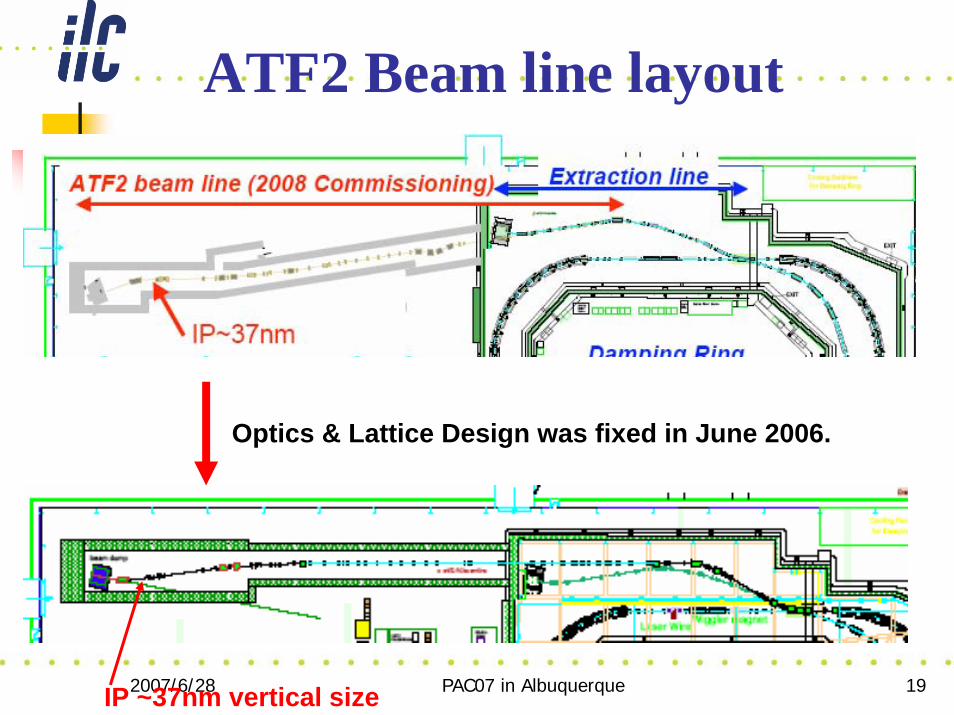
ATF2 Beam line layout
Optics & Lattice Design was fixed in June 2006.
IP ~37nm vertical size
2007/6/28 PAC07 in Albuquerque 20
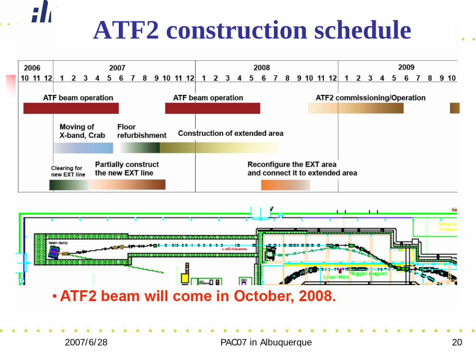
ATF2 construction schedule
2007/6/28 PAC07 in Albuquerque 21
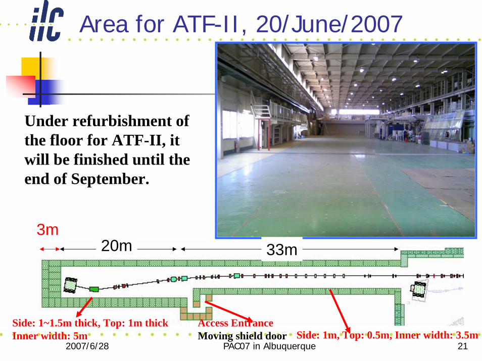
Area for ATF-II, 20/June/2007
Under refurbishment of the floor for ATF-II, it will be finished until the end of September.
33m20m3m
Side: 1~1.5m thick, Top: 1m thickInner width: 5m
Access EntranceMoving shield door Side: 1m, Top: 0.5m, Inner width: 3.5m
2007/6/28 PAC07 in Albuquerque 22
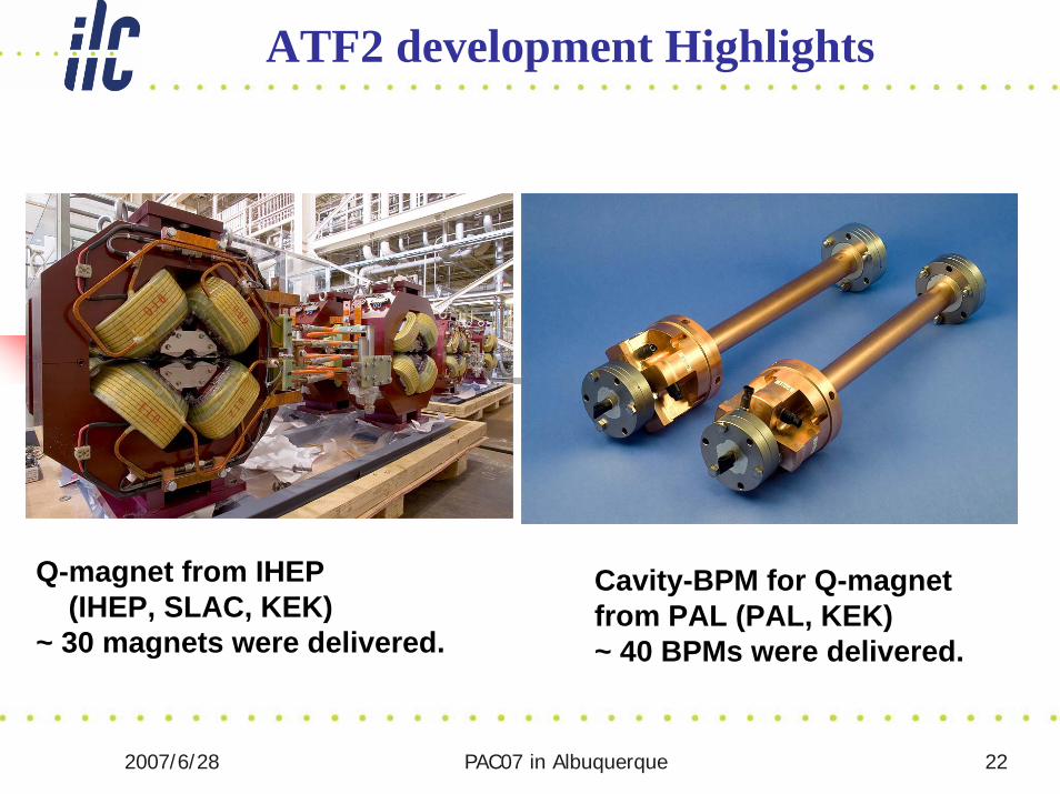
ATF2 development Highlights
Q-magnet from IHEP(IHEP, SLAC, KEK)
~ 30 magnets were delivered.
Cavity-BPM for Q-magnet from PAL (PAL, KEK)~ 40 BPMs were delivered.
2007/6/28 PAC07 in Albuquerque 23
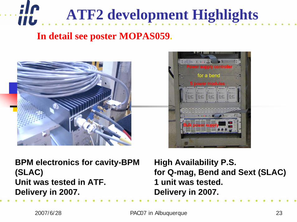
ATF2 development Highlights
BPM electronics for cavity-BPM(SLAC)Unit was tested in ATF.Delivery in 2007.
High Availability P.S. for Q-mag, Bend and Sext (SLAC)1 unit was tested.Delivery in 2007.
In detail see poster MOPAS059.
2007/6/28 PAC07 in Albuquerque 24
ATF2 development Highlights
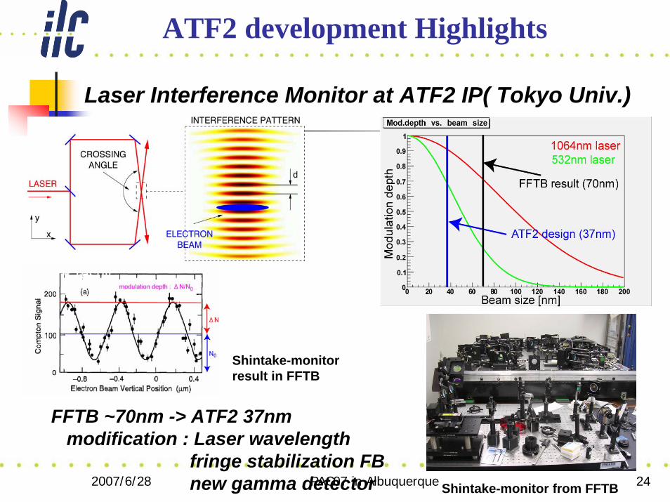
Laser Interference Monitor at ATF2 IP( Tokyo Univ.)
FFTB ~70nm -> ATF2 37nmmodification : Laser wavelength
fringe stabilization FBnew gamma detector
FFTB result
Shintake-monitorresult in FFTB
Shintake-monitor from FFTB
2007/6/28 PAC07 in Albuquerque 25
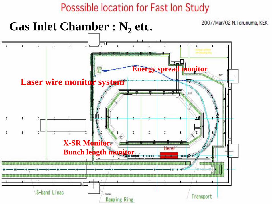
Gas Inlet Chamber : N2 etc.
Laser wire monitor systemEnergy spread monitor
X-SR Monitor,Bunch length monitor
2007/6/28 PAC07 in Albuquerque 26
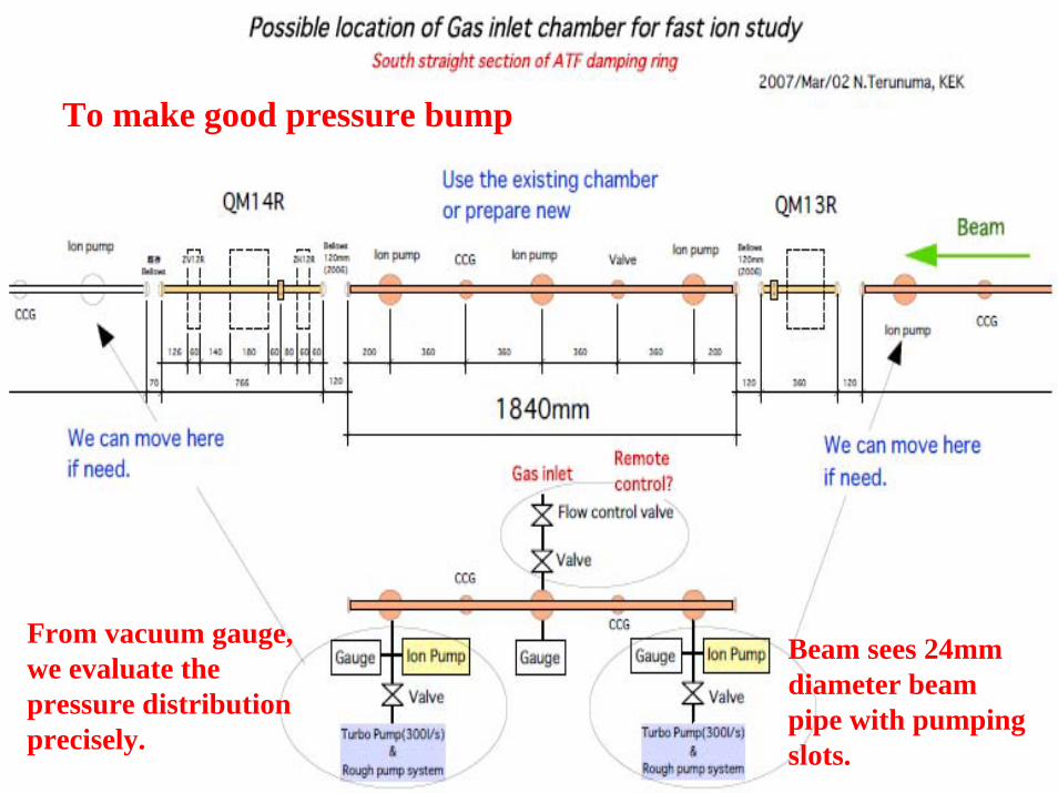
To make good pressure bump
Beam sees 24mmdiameter beampipe with pumpingslots.
From vacuum gauge,we evaluate the pressure distribution precisely.
2007/6/28 PAC07 in Albuquerque 27
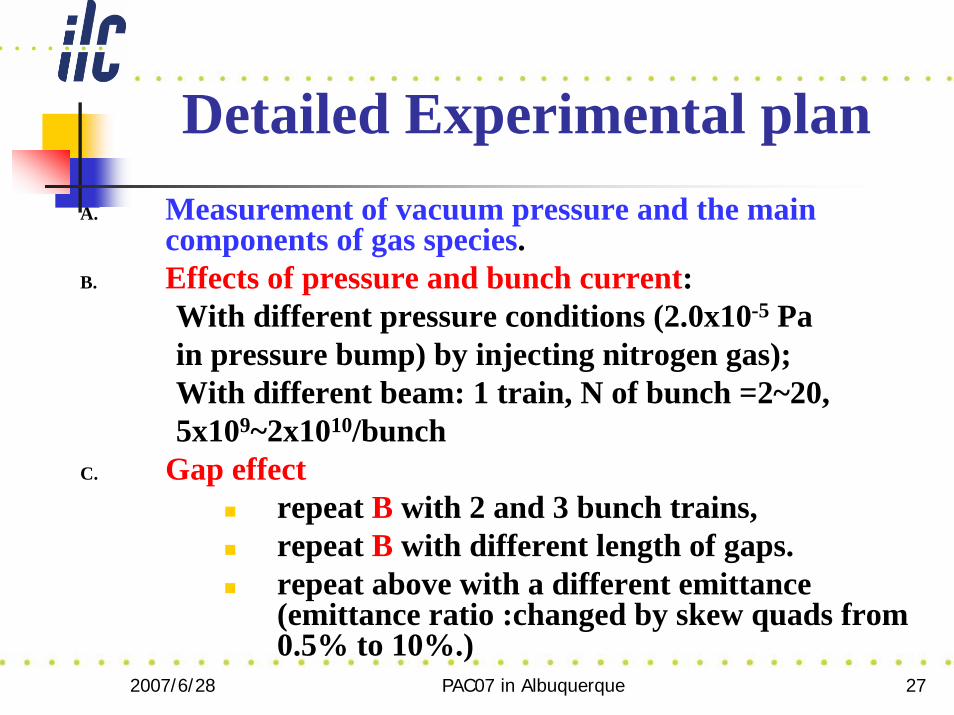
Detailed Experimental planA. Measurement of vacuum pressure and the main
components of gas species.B. Effects of pressure and bunch current:
With different pressure conditions (2.0x10⁻⁵ Pa in pressure bump) by injecting nitrogen gas); With different beam: 1 train, N of bunch =2~20,5x10⁹~2x10¹⁰/bunch
C. Gap effectrepeat B with 2 and 3 bunch trains, repeat B with different length of gaps.repeat above with a different emittance(emittance ratio :changed by skew quads from 0.5% to 10%.)
2007/6/28 PAC07 in Albuquerque 28
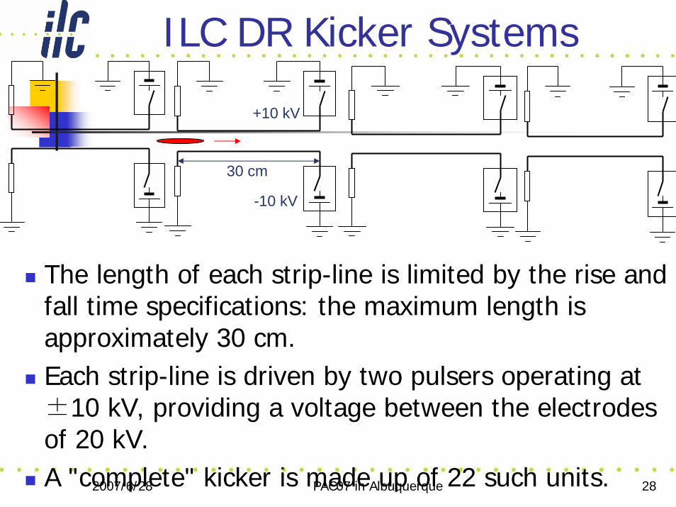
ILC DR Kicker Systems
The length of each strip-line is limited by the rise and fall time specifications: the maximum length is approximately 30 cm.Each strip-line is driven by two pulsers operating at ±10 kV, providing a voltage between the electrodes of 20 kV.A "complete" kicker is made up of 22 such units.
+10 kV
-10 kV
30 cm
2007/6/28 PAC07 in Albuquerque 29
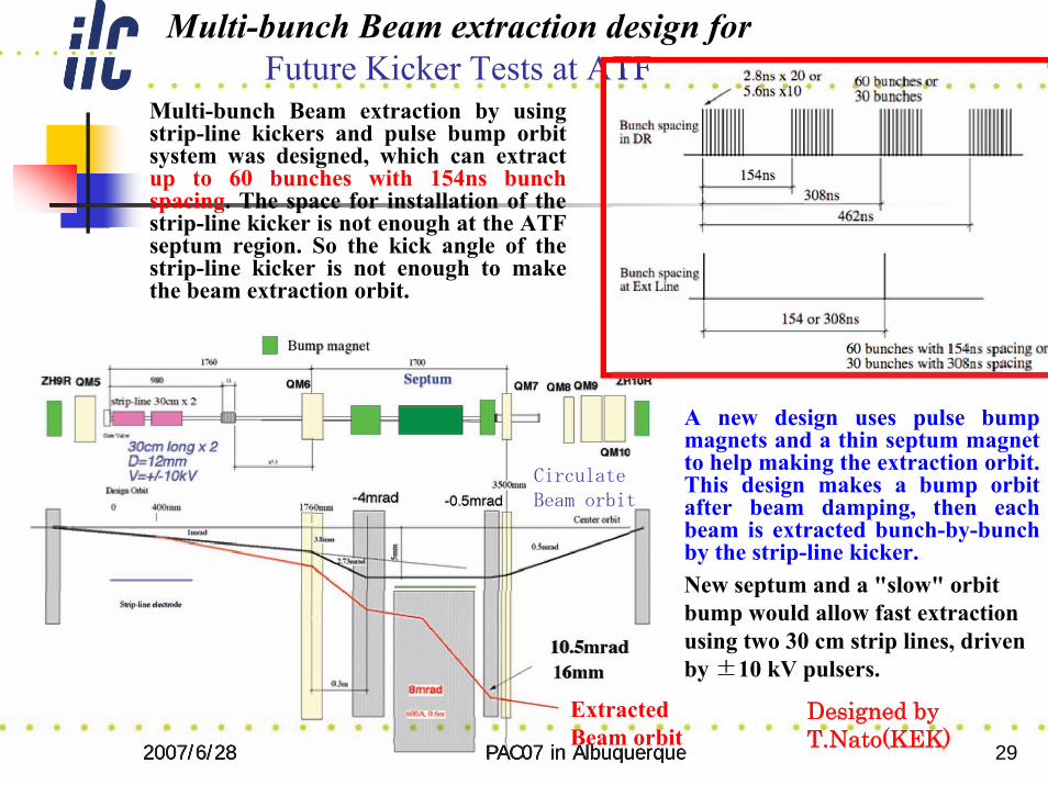
Multi-bunch Beam extraction design for Future Kicker Tests at ATF
A new design uses pulse bump magnets and a thin septum magnet to help making the extraction orbit. This design makes a bump orbit after beam damping, then each beam is extracted bunch-by-bunch by the strip-line kicker.New septum and a "slow" orbit bump would allow fast extraction using two 30 cm strip lines, driven by 10 kV pulsers.
2007/6/28 PAC07 in Albuquerque 29
Multi-bunch Beam extraction by using strip-line kickers and pulse bump orbit system was designed, which can extract up to 60 bunches with 154ns bunch spacing. The space for installation of the strip-line kicker is not enough at the ATF septum region. So the kick angle of the strip-line kicker is not enough to make the beam extraction orbit.
Designed by T.Nato(KEK)
ExtractedBeam orbit
Future Kicker Tests at ATFFuture Kicker Tests at ATF
2007/6/28 PAC07 in Albuquerque 30
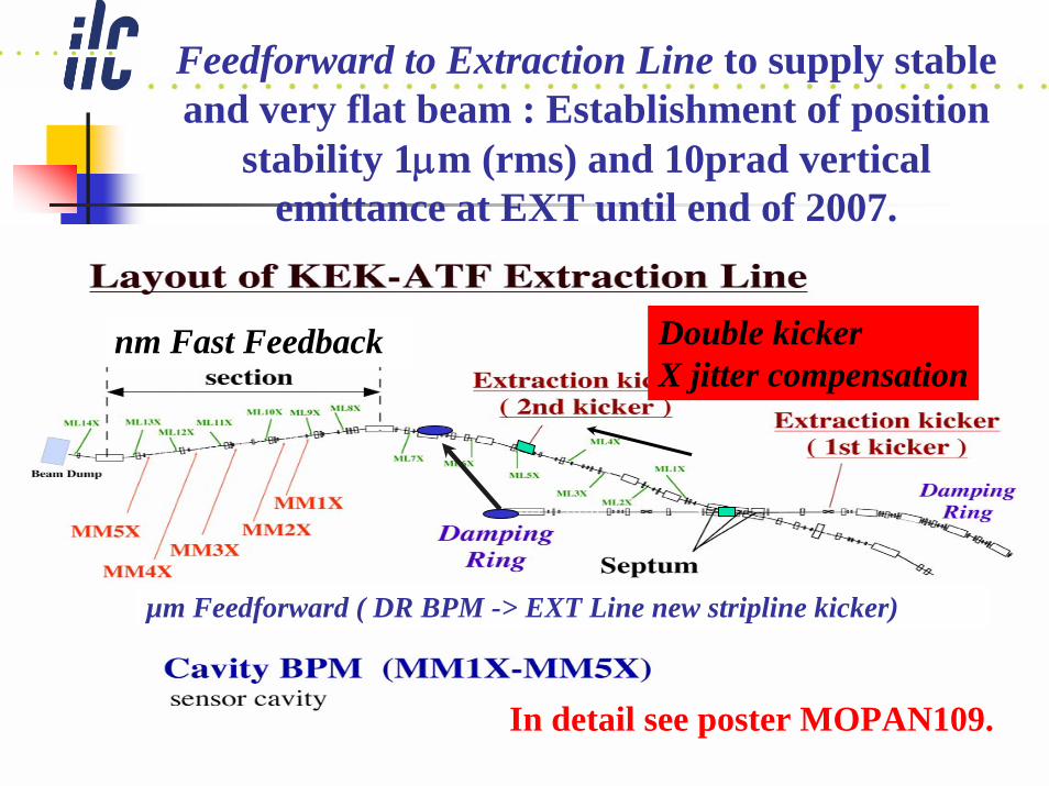
Feedforward to Extraction Line to supply stable and very flat beam : Establishment of position
stability 1μm (rms) and 10prad vertical emittance at EXT until end of 2007.
nm Fast Feedback
µm Feedforward ( DR BPM -> EXT Line new stripline kicker)
Double kicker X jitter compensation
In detail see poster MOPAN109.
2007/6/28 PAC07 in Albuquerque 31
Prospect of ATF
ATF International R&D will generate necessary results for ILC, especially how to control high quality beam, develop many kinds of advanced instrumentation, educate young accelerator physicists and engineers.ILC like beam which means 60 bunches with bunch spacing 154nsec, in the future.Realization of 37nm beam for long period.
2007/6/28 PAC07 in Albuquerque 32
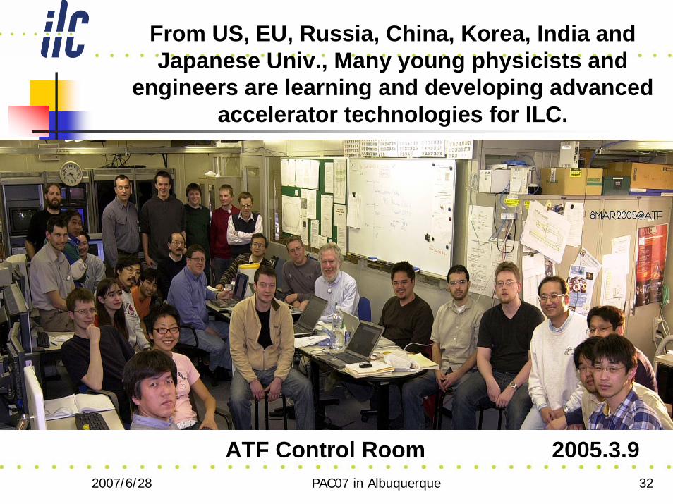
2005.3.9
From US, EU, Russia, China, Korea, India and Japanese Univ., Many young physicists and
engineers are learning and developing advanced accelerator technologies for ILC.
ATF Control Room