atc cybercabinet operation manual
TRANSCRIPT

ATC CyberCabinet® Operation Manual SOFTWARE VERSION 1.5.1.3
November 11, 2021
www.SreServicesLLC.com
INFORMATION CONTAINED HEREIN IS PROPRIETARY TECHNICAL INFORMATION OF SRE SERVICES LLC. PUBLICATION, REPRODUCTION OR USE IN WHOLE OR PART IS NOT
PERMITTED EXCEPT UNDER TERMS AGREED UPON IN WRITING.
CYBERCABINET® IS A TRADEMARK OF SRE SERVICES LLC. MonitorKey® IS A TRADEMARK OF EBERLE DESIGN INC.
DATAKEY® IS A TRADEMARK OF ATEK ACCESS TECHNOLOGIES
© COPYRIGHT 2021 SRE SERVICES LLC
Please register your copy of the ATC CyberCabinet software on-line at
www.SreServicesLLC.com/registration.
This will allow us to notify you of any software update releases.
WARNING
The ATC CyberCabinet emulation of the CMU is a tool to help ensure that the CMU Datakey Configuration is compatible with the Controller database operation. It is up to the User to determine that the CMU Datakey parameters are correct, complete, and suitable for the target intersection.

Table of Contents
Section 1 General ................................................................................................................. 1 1.1 Introduction ........................................................................................................................ 1 1.2 ATC CyberCabinet Overview ............................................................................................... 1 1.3 ATC CyberCabinet Functionality.......................................................................................... 1
1.3.1 CU Direct Mode ........................................................................................................... 2 1.3.1.1 SIU Device View ................................................................................................... 2 1.3.1.2 Intersection Map View ........................................................................................ 2 1.3.1.3 CMU Emulation ................................................................................................... 3 1.3.1.4 Replay Trace Log .................................................................................................. 4 1.3.1.5 Serial Bus #1 Comm Trace Log ............................................................................ 4
1.3.2 SIU Direct Mode .......................................................................................................... 5 1.4 ATC CyberCabinet Package ................................................................................................. 6
Section 2 Installation ............................................................................................................ 7 2.1 Computer (PC) Requirements ............................................................................................. 7 2.2 ATC CyberCabinet Software Downloads ............................................................................. 7 2.3 ATC CyberCabinet Software Installation ............................................................................. 7 2.4 ATC CyberCabinet HDLC Interface Module Driver Installation ........................................... 7 2.5 HDLC Interface Module (HIM) ............................................................................................. 8 2.6 HDLC Interface Module (HIM) Harness Assembly .............................................................. 8 2.7 Software Registration and Updates .................................................................................... 9
Section 3 CU Direct Mode Functions ................................................................................... 10 3.1 General .............................................................................................................................. 10 3.2 Serial Bus #1 Connection to the CU .................................................................................. 10
3.2.1 Multiple HDLC Interface Modules on the Same PC .................................................. 10 3.2.2 Serial Bus #1 Connection in a 33x Cabinet ................................................................ 11
3.2.2.1 2070-2C .............................................................................................................. 11 3.2.2.2 2070-2A (-2E) ..................................................................................................... 12
3.3 Views ................................................................................................................................. 12 3.3.1 SIU Device View ......................................................................................................... 12
3.3.1.1 Detector Device View ........................................................................................ 13 3.3.1.2 SIU Output Misc IO View ................................................................................... 13 3.3.1.3 SIU Device View Text Fields ............................................................................... 13 3.3.1.4 SIU Device View Signal Types ............................................................................ 13 3.3.1.5 SIU Device View Status Panel ............................................................................ 13
3.3.1.5.1 Controller Date and Time ................................................................. 13 3.3.2 Intersection Map View .............................................................................................. 13
3.4 Cabinet Monitor Unit (CMU) ............................................................................................. 14 3.4.1 CMU-2212 ................................................................................................................. 15 3.4.2 2018KCL ..................................................................................................................... 16 3.4.3 Operating the CMU ................................................................................................... 16
3.4.3.1 View CMU Configuration ................................................................................... 16 3.4.3.2 Reset the CMU ................................................................................................... 16
3.4.3.3 Local Flash Control ............................................................................................ 17 3.4.4 Configuring the CMU ................................................................................................. 17
3.4.4.1 Load Datakey File ............................................................................................... 17 3.4.4.2 Read Datakey Direct .......................................................................................... 17
3.5 CU Direct Controls ............................................................................................................. 17 3.5.1 Start / Stop CU Comm ............................................................................................... 17
3.5.1.1 CU Communicating Icon .................................................................................... 17 3.5.2 CMU Status ................................................................................................................ 18 3.5.3 Reset the CMU .......................................................................................................... 18 3.5.4 Replay Mode ............................................................................................................. 18 3.5.5 Clear Replay Log ........................................................................................................ 18 3.5.6 Display Serial Trace Log ............................................................................................. 18 3.5.7 Clear Serial Trace Log ................................................................................................ 18 3.5.8 Clear Checkboxes ...................................................................................................... 18
Section 4 SIU Direct Mode Functions................................................................................... 19 4.1 General .............................................................................................................................. 19 4.2 Serial Connection to the Target SIU-2218......................................................................... 19
4.2.1 SIU-2218 Front Panel Port ......................................................................................... 19 4.3 SIU Direct Mode Functionality .......................................................................................... 20
4.3.1 Connecting the Serial Port......................................................................................... 20 4.3.1.1 Scan Ports Button .............................................................................................. 20 4.3.1.2 Connect Button.................................................................................................. 20 4.3.1.3 Disconnect Button ............................................................................................. 20 4.3.1.4 AutoConnect Enable .......................................................................................... 20 4.3.1.5 Close .................................................................................................................. 20
4.3.2 SIU IO Views .............................................................................................................. 21 4.3.2.1 Input SIU ............................................................................................................ 21 4.3.2.2 Output SIU ......................................................................................................... 21
4.3.3 SIU Direct Controls .................................................................................................... 21 4.3.3.1 Start Poll ............................................................................................................ 21
4.3.3.1.1 SIU Communicating Icon .................................................................. 21 4.3.3.2 Input Control ..................................................................................................... 22 4.3.3.3 Output Control .................................................................................................. 22
4.3.4 Clear Checkboxes ...................................................................................................... 22 4.3.4.1 Capture Checkboxes .......................................................................................... 22
4.3.5 Display Serial Log ....................................................................................................... 22 4.3.6 Clear Serial Log .......................................................................................................... 22
Section 5 Main Menus ........................................................................................................ 23 5.1 Menu: File ......................................................................................................................... 23
5.1.1 Project File ................................................................................................................. 23 5.1.1.1 Open Project File ............................................................................................... 23 5.1.1.2 Save Project File................................................................................................. 23
5.1.2 Exit ............................................................................................................................. 23

5.2 Menu: Configuration ......................................................................................................... 23 5.2.1 Cabinet Type .............................................................................................................. 23 5.2.2 Operating Mode ........................................................................................................ 24 5.2.3 Open Comm Port ....................................................................................................... 24
5.2.3.1 Connect USB (CU Direct Mode) ......................................................................... 24 5.2.3.2 Connect COMM (SIU Direct Mode) ................................................................... 24
5.2.4 SIU Enables ................................................................................................................ 24 5.2.5 Settings ...................................................................................................................... 24
5.3 Menu: View ....................................................................................................................... 26 5.3.1 View CMU .................................................................................................................. 26 5.3.2 Intersection Map View .............................................................................................. 26 5.3.3 View Replay Log ........................................................................................................ 26
5.3.3.1 Capture New Replay Log ................................................................................... 26 5.3.3.2 Open Saved Replay Log ..................................................................................... 26
5.3.4 View Serial Comm Trace Log ..................................................................................... 26 5.3.4.1 Capture New Trace Log ..................................................................................... 27 5.3.4.2 Open Saved Trace Log ....................................................................................... 27
5.4 Menu: Window.................................................................................................................. 27 5.4.1 Tile ............................................................................................................................. 27 5.4.2 Cascade ...................................................................................................................... 27 5.4.3 Center All Windows ................................................................................................... 27
5.5 Menu: Help ........................................................................................................................ 28 5.5.1 IO Maps ..................................................................................................................... 28 5.5.2 AbouT ........................................................................................................................ 28
Section 6 Cabinet Monitor Unit (CMU) ................................................................................ 29 6.1 General .............................................................................................................................. 29 6.2 CMU Functionality ............................................................................................................. 29
6.2.1 CMU Channel Display ................................................................................................ 29 6.2.2 Fault Coverage ........................................................................................................... 30
6.2.2.1 Conflict ............................................................................................................... 30 6.2.2.2 Lack of Signal (LOS) or Red Fail .......................................................................... 30
6.2.2.2.1 Dark Maps ........................................................................................ 30 6.2.2.3 Multiple Signal ................................................................................................... 30 6.2.2.4 Clearance ........................................................................................................... 30
6.2.2.4.1 Minimum Yellow Clearance ............................................................. 30 6.2.2.4.2 Minimum Yellow + Red Clearance ................................................... 30
6.2.2.5 Flashing Yellow Arrow ....................................................................................... 30 6.2.2.5.1 FYA Flash Rate .................................................................................. 30 6.2.2.5.2 FYA R&Y Enable ................................................................................ 30 6.2.2.5.3 FYA Yellow Trap ................................................................................ 30
6.2.2.6 Virtual Channels ................................................................................................ 31 6.2.2.7 Serial Bus #1 Timeout ........................................................................................ 31 6.2.2.8 WDT Timeout ..................................................................................................... 31

6.2.2.9 Local Flash Input ................................................................................................ 31 6.3 Operating the CMU ........................................................................................................... 31
6.3.1 Reset CMU ................................................................................................................. 31 6.3.2 Local Flash ................................................................................................................. 31 6.3.3 Disable SB#1 Fault ..................................................................................................... 31 6.3.4 Trigger Replay Log on Fault ....................................................................................... 31 6.3.5 Trigger Trace Log on Fault ......................................................................................... 32
6.4 CMU Menu Items .............................................................................................................. 32 6.4.1 CMU Menu ................................................................................................................ 32
6.4.1.1 Enable / Disable CMU ........................................................................................ 32 6.4.1.2 Configure CMU Logic Outputs ........................................................................... 32
6.4.1.2.1 CMU Reset Input .............................................................................. 32 6.4.1.2.2 CMU Flash Sense Output ................................................................. 32 6.4.1.2.3 CMU Stop Time Output .................................................................... 32
6.4.2 Datakey Menu ........................................................................................................... 32 6.4.2.1 Open Datakey File ............................................................................................. 33 6.4.2.2 Read Datakey ..................................................................................................... 33
6.4.3 View Menu ................................................................................................................ 33 6.4.3.1 CMU Fault Log ................................................................................................... 33
6.4.3.1.1 Refresh Log ....................................................................................... 33 6.4.3.1.2 Save Log............................................................................................ 33 6.4.3.1.3 Clear Log ........................................................................................... 33
6.4.3.2 CMU Configuration ............................................................................................ 33
Section 7 Map Editor .......................................................................................................... 35 7.1 General .............................................................................................................................. 35 7.2 MAP Files ........................................................................................................................... 35
7.2.1 Open MAP file ........................................................................................................... 35 7.2.1.1 Open MAP as Overlay ........................................................................................ 35
7.2.2 Save MAP file ............................................................................................................. 35 7.3 MAP Icons .......................................................................................................................... 35 7.4 Edit Mode and Run Mode ................................................................................................. 37 7.5 Editor Functions ................................................................................................................ 37
7.5.1 New Icon .................................................................................................................... 37 7.5.1.1 Detector Details ................................................................................................. 37
7.5.1.1.1 Volume / Occupancy Detector ......................................................... 37 7.5.1.2 Signal Details ..................................................................................................... 38
7.5.1.2.1 Beacon Signal Type .......................................................................... 38 7.5.1.3 Inspecting Detector and Signal Assignments .................................................... 39 7.5.1.4 Modifying Detector and Signal Assignments .................................................... 39
7.5.2 Select ......................................................................................................................... 39 7.5.2.1 Pinned Icons ...................................................................................................... 39
7.5.3 Move .......................................................................................................................... 39 7.5.4 Resize ......................................................................................................................... 39

7.5.5 Rotate ........................................................................................................................ 39 7.5.6 Delete ........................................................................................................................ 40 7.5.7 Duplicate ................................................................................................................... 40 7.5.8 Send To Front ............................................................................................................ 40 7.5.9 Send to Back .............................................................................................................. 40
Section 8 Replay Mode ...................................................................................................... 41 8.1 General .............................................................................................................................. 41 8.2 Capturing the Replay Trace Log ........................................................................................ 41
8.2.1 Save Log ..................................................................................................................... 41 8.2.2 Open Log ................................................................................................................... 41
8.3 Replay Mode ..................................................................................................................... 42 8.3.1 End Replay ................................................................................................................. 42 8.3.2 Play ............................................................................................................................ 42 8.3.3 Play 2x........................................................................................................................ 43 8.3.4 Step ............................................................................................................................ 43 8.3.5 Pause ......................................................................................................................... 43 8.3.6 Replay ........................................................................................................................ 43 8.3.7 Replay Start ............................................................................................................... 43 8.3.8 Replay Progress ......................................................................................................... 43
Section 9 Serial Comm Trace Log ......................................................................................... 44 9.1 General .............................................................................................................................. 44 9.2 Capturing the Serial Comm Trace Log ............................................................................... 44 9.3 Display Mode..................................................................................................................... 44
9.3.1 Save Log ..................................................................................................................... 44 9.3.2 Open Log ................................................................................................................... 44
Section 10 SIU IO Maps ....................................................................................................... 45 10.1 General ............................................................................................................................ 45 10.2 ATC Cabinet ..................................................................................................................... 45
10.2.1 Input SIU .................................................................................................................. 45 10.2.2 Output SIU ............................................................................................................... 45
10.3 IO Combo (BackPack) ...................................................................................................... 46 10.4 NYCDOT LPLVC Cabinet ................................................................................................... 46 10.5 LADOT 332 Cabinet ......................................................................................................... 47
10.5.1 Input ........................................................................................................................ 47 10.5.2 Output ..................................................................................................................... 47
10.6 TEES 332 Cabinet ............................................................................................................. 47 10.6.1 Output ..................................................................................................................... 47
Section 11 Trouble Shooting ............................................................................................... 49 11.1 HDLC Interface Module Test ........................................................................................... 49
11.1.1 HDLC Interface Module USB Port ............................................................................ 49 11.2 HDLC Interface Module Loopback Test ........................................................................... 49 11.3 HDLC Interface Module Warranty................................................................................... 50

11.4 Technical Support ............................................................................................................ 50

ATC CyberCabinet Operation Manual Page 1
General
Section 1 General
1.1 INTRODUCTION
This manual covers the installation and operation of the ATC CyberCabinet® Software package running on a Microsoft Windows 10 based Personal Computer (PC). It provides the user with a general understanding of the operating principles necessary to install and operate the ATC CyberCabinet software.
1.2 ATC CYBERCABINET OVERVIEW
The ATC CyberCabinet program provides a traffic signal Engineer with a software based solution to emulate the functionality of an ATC5301 Standard ATC Cabinet without needing a full cabinet assembly in hardware. The Advanced Transportation Controller Unit (CU) being tested will interface to the ATC CyberCabinet software via the ATC CyberCabinet HDLC Interface Module hardware.
The ATC CyberCabinet software emulates the functionality of the ATCC Cabinet Monitor Unit (CMU) and input/output Serial Interface Units (SIU). Up to seven SIUs are supported, two Output SIUs and five Input SIUs. Several different configurations of ATC cabinets are supported (See Section 5.2.1):
• Standard Input Assembly (24 or 48 channel) o Up to five SIUs for 120 Input channels
• Standard 16 Channel Output Assembly • Standard 32 Channel Output Assembly • Combo IO Assembly (future) • NYCDOT LPLVC • Caltrans TEES 33x Cabinets
1.3 ATC CYBERCABINET FUNCTIONALITY
The ATC CyberCabinet software is intersection project based and operates in two basic modes, the CU Direct mode and the SIU Direct mode. Once a project has been created with the relevant program configuration, it can be stored to a PC disk file and retrieved again, eliminating repetitive software setup steps.
ATC CyberCabinet Operation Manual Page 2
General
1.3.1 CU DIRECT MODE
In the CU Direct mode, the ATC CyberCabinet software responds to HDLC commands from the target Controller Unit via SB#1 using the ATC CyberCabinet HDLC Interface Module (HIM) and adaptor cable. Only the target CU is a physical device and the cabinet CMU and SIUs are all virtualized in the ATC CyberCabinet software.
In the CU Direct mode two different operating view options are provided; the SIU Device view, and the Intersection Map view. Both can be viewed simultaneously depending on the operator preference.
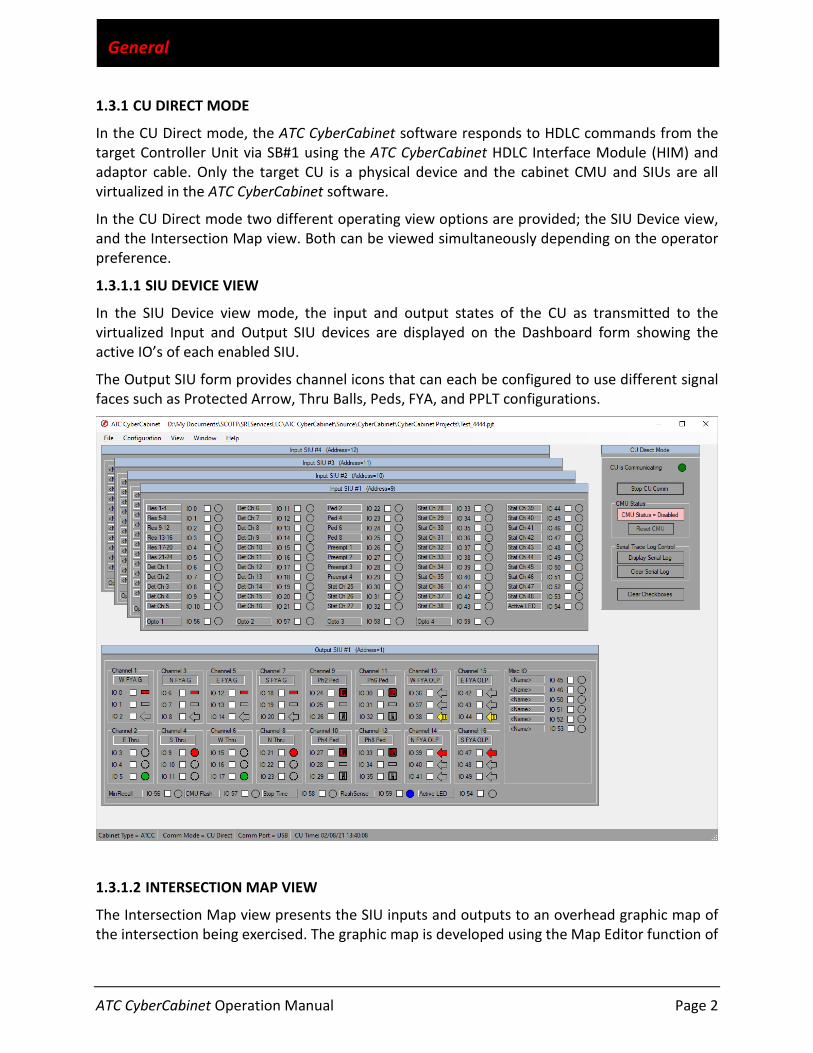
1.3.1.1 SIU DEVICE VIEW
In the SIU Device view mode, the input and output states of the CU as transmitted to the virtualized Input and Output SIU devices are displayed on the Dashboard form showing the active IO’s of each enabled SIU.
The Output SIU form provides channel icons that can each be configured to use different signal faces such as Protected Arrow, Thru Balls, Peds, FYA, and PPLT configurations.
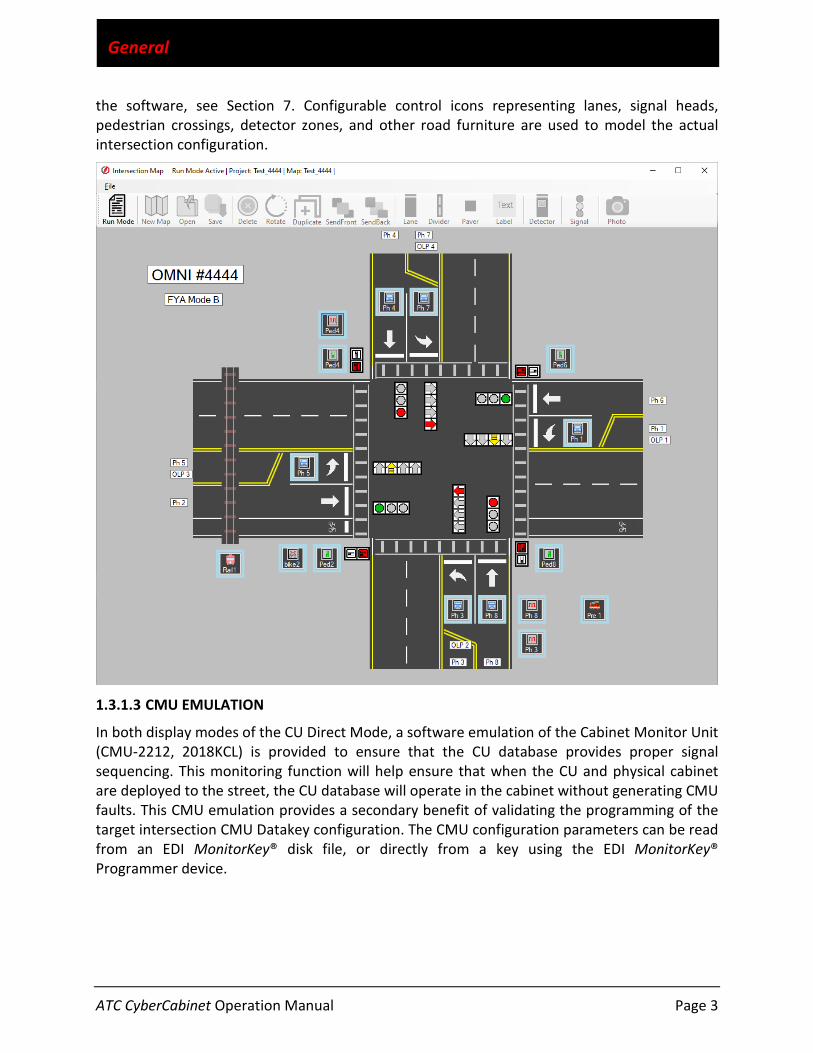
1.3.1.2 INTERSECTION MAP VIEW
The Intersection Map view presents the SIU inputs and outputs to an overhead graphic map of the intersection being exercised. The graphic map is developed using the Map Editor function of
ATC CyberCabinet Operation Manual Page 3
General
the software, see Section 7. Configurable control icons representing lanes, signal heads, pedestrian crossings, detector zones, and other road furniture are used to model the actual intersection configuration.
1.3.1.3 CMU EMULATION
In both display modes of the CU Direct Mode, a software emulation of the Cabinet Monitor Unit (CMU-2212, 2018KCL) is provided to ensure that the CU database provides proper signal sequencing. This monitoring function will help ensure that when the CU and physical cabinet are deployed to the street, the CU database will operate in the cabinet without generating CMU faults. This CMU emulation provides a secondary benefit of validating the programming of the target intersection CMU Datakey configuration. The CMU configuration parameters can be read from an EDI MonitorKey® disk file, or directly from a key using the EDI MonitorKey® Programmer device.

ATC CyberCabinet Operation Manual Page 4
General
1.3.1.4 REPLAY TRACE LOG
A timestamped sequential log is collected that can be used to temporarily halt the real-time display and replay approximately five minutes of the controller sequence. See Section 8.
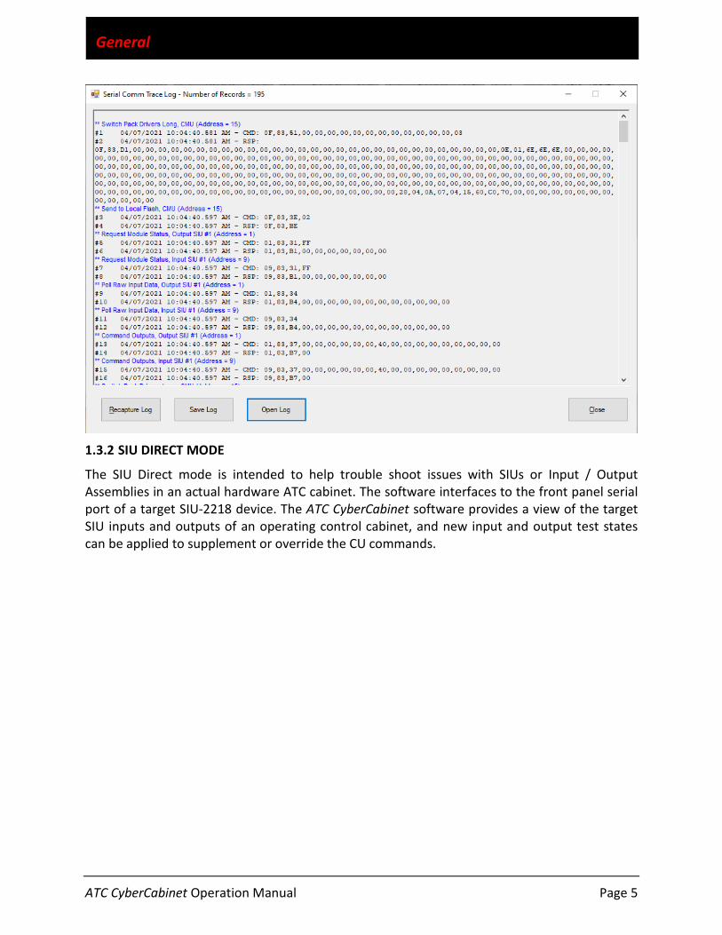
1.3.1.5 SERIAL BUS #1 COMM TRACE LOG
A timestamped sequential log is collected that acts as an SB#1 bus sniffer, presenting a complete record of SB#1 HDLC activity. Each Command frame issued by the CU and each corresponding Response frame from the addressed device is recorded and timestamped in a log format for review along with the frame contents. See Section 5.3.3 and Section 9.
ATC CyberCabinet Operation Manual Page 5
General
1.3.2 SIU DIRECT MODE
The SIU Direct mode is intended to help trouble shoot issues with SIUs or Input / Output Assemblies in an actual hardware ATC cabinet. The software interfaces to the front panel serial port of a target SIU-2218 device. The ATC CyberCabinet software provides a view of the target SIU inputs and outputs of an operating control cabinet, and new input and output test states can be applied to supplement or override the CU commands.

ATC CyberCabinet Operation Manual Page 6
General
1.4 ATC CYBERCABINET PACKAGE
The ATC CyberCabinet package includes:
• ATC CyberCabinet software for Microsoft Windows 10 • ATC CyberCabinet HDLC Interface Module (HIM) • ATC CyberCabinet Harness Assembly • ATC CyberCabinet USB Cable • ATC CyberCabinet HDLC Interface Module Loopback Plug

ATC CyberCabinet Operation Manual Page 7
Installation
Section 2 Installation
2.1 COMPUTER (PC) REQUIREMENTS
To run the ATC CyberCabinet software, the following equipment is required:
• Personal Computer running Microsoft Windows 10 (32 or 64 bit). • Available USB port • ATC CyberCabinet HDLC Interface Module (HIM) • If the optional SIU Direct Mode is used:
o PC Serial Port or Serial Port to USB Null Modem adaptor. o The SIU-2218 requires a Null Modem connection to the front panel serial port.
2.2 ATC CYBERCABINET SOFTWARE DOWNLOADS
Download the ATC CyberCabinet Installation packages from the SRE Services web site at: www.SreServicesLLC.com/Downloads. Extract both ZIP files to a temporary directory.
• ATC_CyberCabinet_Install.ZIP o Setup.exe o SetupCyberCabinet.msi
• ATC_CyberCabinet_Driver.ZIP o Windows Driver Folder
Optional:
• Loopback-Test.ZIP (optional) o Loopback-Test.exe
• ATC CyberCabinet Operation Manual (PDF)
2.3 ATC CYBERCABINET SOFTWARE INSTALLATION
The installation process is two steps; software install and USB driver install. To begin the software install, RIGHT click the Setup.exe file and select Run as Administrator. Follow the steps of the installation wizard. Once the installation is complete there will be a shortcut added to the Windows Start menu: ATC CyberCabinet.
2.4 ATC CYBERCABINET HDLC INTERFACE MODULE DRIVER INSTALLATION
To begin the USB driver install, follow the steps below:
1. Close all programs before installing this hardware. 2. Plug the USB cable into an open USB port on the PC. 3. The Windows Device Manager should pop up. If it doesn’t, open the Device Manager
manually. (Type DEVICE MANAGER in the Ask me anything bar at the bottom left of the screen).
4. On the Device Manager, look for Serial/USB in “Other devices”. RIGHT click on Serial/USB.

ATC CyberCabinet Operation Manual Page 8
Installation
5. Click on Update Driver Software. Next, click on “Browse my computer for driver software”.
6. Select the Windows Driver folder that was extracted in Section 2.2 above. 7. In the Windows Driver folder, select “64_win10” for Windows 10, 64 bit. 8. Click on OK then click on NEXT. The HDLC Interface Module Drive driver is now installed.
You can close the Update Driver Software window. 9. See Section 11 for trouble-shooting information if needed.
2.5 HDLC INTERFACE MODULE (HIM)
The HDLC Interface Module provides four LED indictors for operational status.
• Power OK: indicates USB power is being provided. • Operation OK: indicates that the internal circuits are ready. • Rx Activity: indicates that HDLC data is being received. • Tx Activity: indicates that HDLC data is being transmitted
.
2.6 HDLC INTERFACE MODULE (HIM) HARNESS ASSEMBLY
DB25 Pin # Female
HIM Controller DB25 Pin# Male
1 Ground Ground 13 2 TxC- Out RxC- In 17 3 TxD- Out RxD- In 15
12 RxD- In TxD- Out 14 13 RxC- In TxC- Out 16 14 TxC+ Out RxC+ In 4 15 TxD+ Out RxD+ In 2 24 RxD+ In TxD+ Out 1 25 RxC+ In TxC+ Out 3
If additional cable length is needed between the Controller and the HDLC Interface Module, a DB25 Male/Female extender cable can be connected between the Controller port and the HDLC Interface Module harness assembly. The HDLC Interface Module harness assembly is always connected directly to the HDLC Interface Module.
Power OK
Operation OK
Rx Activity
Tx Activity

ATC CyberCabinet Operation Manual Page 9
Installation
2.7 SOFTWARE REGISTRATION AND UPDATES
The most current version of the ATC CyberCabinet software can be downloaded from the SRE Services web site at www.SREservicesLLC.com/Downloads.
Before installing a new update, the currently installed version of the ATC CyberCabinet program should first be uninstalled from the computer.
Please register your copy of the ATC CyberCabinet software on-line at
www.SreServicesLLC.com/registration.
This will allow us to notify you of future software update releases.

ATC CyberCabinet Operation Manual Page 10
CU Direct Mode Functions
Section 3 CU Direct Mode Functions
3.1 GENERAL
The primary operating mode of the ATC CyberCabinet software is the CU Direct Mode. This mode emulates the CMU and SIU devices found in the ATC traffic cabinet, and the CMU and FIO found in a 33x cabinet. All input and output functions of the Controller Unit (CU) can be displayed and modified to exercise the CU program.
The CU Direct Mode is selected using the Main Menu: Configuration / Operating Mode (see Section 5.2.2)
A typical procedure to create a new project or session is to:
• Configure the Cabinet Type (Section 5.2.1) • Select the Operating Mode (Section 5.2.2) • Configure the SIUs installed in the cabinet5.2.4
o SIU Enables (Section 5.2.4) o SIU IO Text Fields (optional) (Section 3.3.1.1) o Signal Face Types (optional) (Section 3.3.1.4)
• Use the Map Editor to build a map (optional) (Section 7) • Connect the HDLC Interface Module to the CU (Section 5.2.3.1) • Configure/enable the CMU (optional) (Section 5.3.1) • Select the desired View (Section 5.35.3.2) • Click the Start CU Comm button (CU Direct Control panel) (Section 3.5.1) • When done, save the project file (Section 5.1.1.2)
3.2 SERIAL BUS #1 CONNECTION TO THE CU
The ATC CyberCabinet connects to the target Controller Unit via the ATC CyberCabinet HDLC Interface Module (HIM). This module provides an HDLC to USB translation and requires one available USB port on the PC. A provided interconnect harness is used to connect the ATC CyberCabinet HDLC Interface Module to the Serial Bus #1 port of the Controller Unit.
3.2.1 MULTIPLE HDLC INTERFACE MODULES ON THE SAME PC
The ATC CyberCabinet software can run as separate instances on the same PC as long as the PC can support the USB load and display loading. One additional HDLC Interface Module is needed

ATC CyberCabinet Operation Manual Page 11
CU Direct Mode Functions
for each instance (controller). As each additional HDLC Interface Module is added, Windows will assign it an incrementing USB address, starting from 0. The USB address used by each instance of the ATC CyberCabinet software is assigned with a command line option when launching the program. Create a shortcut to the installed version of the ATC CyberCabinet software. Edit the properties of this shortcut, adding the option /usb=X to the end of the Target field, where X is the number of the USB port of the added HDLC Interface Module. Be sure that this option text is outside of any quotes within the Target field. For example, this is the shortcut to launch the software for the second (X=1) HDLC Interface Module:
This shortcut process is only needed if additional HDLC Interface Modules are added. For a single instance, the program defaults to USB address 0.
3.2.2 SERIAL BUS #1 CONNECTION IN A 33X CABINET
To operate the ATC CyberCabinet software in a Caltrans 33x cabinet mode requires a 2070 controller with two options for the FIO configuration, a 2017-2A (-2E) card or a 2070-2C card. The controller must have a 2070 FIO card installed that either does not provide the FCU function (-2C) or an FIO card that can be configured to disable the hardware Field-IO Controller Unit (FCU) function.
3.2.2.1 2070-2C
The 2070-2C FIO card provides the SB#1 interface to the C12S connector without an internal FCU function. This card can be used with the ATC CyberCabinet directly.

ATC CyberCabinet Operation Manual Page 12
CU Direct Mode Functions
3.2.2.2 2070-2A (-2E)
The 2070-2A (-2E) cards have a built-in FCU. This hardware FCU must be disabled in order to work with the ATC CyberCabinet. In this case the C12S connector provides the SB#1 communications to the HDLC Interface Module, and the ATC CyberCabinet will be emulating the disabled hardware FCU.
3.3 VIEWS
3.3.1 SIU DEVICE VIEW
The main dashboard view provides a view of the input and output SIUs that are enabled (see Section 5.2.4). These SIUs are always visible. The Main Menu: Windows / Tile (or Cascade) (see Section 5.4) can be used to optimize the dashboard view once the appropriate SIUs are enabled.
Note that not all 2070-2A (-2E) cards have an option to disable the FCU function.
For example, the McCain 2070-2A card has an option to remove the two socketed Eprom chips of the FCU processor. This disables the FCU.

ATC CyberCabinet Operation Manual Page 13
CU Direct Mode Functions
3.3.1.1 DETECTOR DEVICE VIEW
In the ATCC mode, the Input SIUs can be displayed as SIU devices or 4-channel Detector devices if desired. See Section 5.2.5.
3.3.1.2 SIU OUTPUT MISC IO VIEW
In the ATCC mode, the Misc IO icons of the Output SIUs can be displayed or hidden. Misc IOs are those IO pins of the Output SIUs that are not defined by ATC5301. See Section 5.2.5.
3.3.1.3 SIU DEVICE VIEW TEXT FIELDS
The text fields of the Input and Output SIU panels of a project should be populated to help with identifying the function of each input or output. These fields will also assist when developing a Map view, see Section 7.5.1.1 and 7.5.1.2.
3.3.1.4 SIU DEVICE VIEW SIGNAL TYPES
The signal face icon of an Output SIU panel can be changed to match the function of the channel. The text fields and signal face types will be used when adding signals to a Map view, see Section 7.5.1.2, and on the CMU view. To modify the signal face type, right click on a signal face of the channel group, and select the proper signal type (View or Modify).
3.3.1.5 SIU DEVICE VIEW STATUS PANEL
At the bottom of the Siu Device View form is a status panel that displays the Cabinet Type, Comm Mode, Comm Port and Controller Date and Time.
3.3.1.5.1 CONTROLLER DATE AND TIME
The status bar at the bottom of the SIU Device view form displays the Date and Time reported by the Controller via SB#1. If the time reported is offset from the PC time by greater than the Controller Time Offset Threshold parameter (see Section 5.2.5), then the panel is shaded pink, and displays the offset value in seconds.
3.3.2 INTERSECTION MAP VIEW
The intersection Map view is a separate form and once configured, displays the overhead intersection layout with active icons mapped to the SIU inputs and outputs. To create or modify an intersection map, use the Intersection Map Editor (see Section 7). Once configured, the Detector control icons can be used to drive CU inputs and the Signal control icons will display the CU signal outputs.

ATC CyberCabinet Operation Manual Page 14
CU Direct Mode Functions
3.4 CABINET MONITOR UNIT (CMU)
The Cabinet Monitor Unit (CMU) emulates a 32 channel CMU-2212 device found in the ATC cabinet, or a 2018KCL device found in a 33x cabinet.
CAUTION
While the functionality of the ATC CyberCabinet CMU is designed to accurately emulate an actual hardware CMU, under some conditions there may be timing differences between this virtual CMU and a real CMU device that results in a different fault detection outcome.

ATC CyberCabinet Operation Manual Page 15
CU Direct Mode Functions
The use of this CMU function is optional. However most Controller Units will require that the Datakey parameters be provided to the CU via SB#1 in order to exit flash. Even if the CMU function is not enabled, the Datakey parameters should be loaded (Section 6.4.1.2).
If the CMU is not Enabled (Section 6.4.1.1) then no cabinet flash will be generated if a signal fault occurs. This can be a useful technique to trouble shoot signal sequences such a preemption event, without interruption from the CMU.
3.4.1 CMU-2212
The ATC CyberCabinet CMU-2212 monitoring functions include the following:
• Open / Read a Datakey configuration • Conflict • Lack of Signal
o Dark Maps • Multiple Signal • Clearance
o Minimum Yellow Clearance o Minimum Yellow + Red Clearance
• Flashing Yellow Arrow o FYA Yellow Trap o FYA Flash Rate o R & Y Input Enable
• Virtual Channels • Serial Bus #1 Timeout • Local Flash Input • Exit Flash Call Start-up Function

ATC CyberCabinet Operation Manual Page 16
CU Direct Mode Functions
3.4.2 2018KCL
The ATC CyberCabinet CMU 2018KCL monitoring functions include the following:
• Open / Read a Datakey configuration • Conflict • Red Fail • Multiple Signal • Clearance
o Minimum Yellow Clearance o Minimum Yellow + Red Clearance
• Flashing Yellow Arrow o FYA mode o FYAC mode o H mode o FYAC Flash Rate
• Watchdog Timeout • Local Flash Input
3.4.3 OPERATING THE CMU
Before the CMU function can be enabled, a Datakey database must be loaded. See Section 3.4.2 for details. Once the Datakey has been successfully loaded, the CMU function is enabled using the CMU Menu: CMU / Enable CMU.
The CU Direct Mode can be operated with or without the CMU function enabled.
3.4.3.1 VIEW CMU CONFIGURATION
The CMU configuration parameters used from the loaded Datakey configuration can be reviewed using the CMU Menu: View / CMU Configuration.
3.4.3.2 RESET THE CMU
If the CMU has detected a fault condition, it will latch the state of the signal channels and display the type of fault detected along with channel fault status. The CMU can be reset to the No-Fault state by clicking the CMU Reset CMU button.
ATC CyberCabinet Operation Manual Page 17
CU Direct Mode Functions
3.4.3.3 LOCAL FLASH CONTROL
To place the CMU into the non-latched Local Flash state, click on the CMU Local Flash button. During a Local Flash condition the CMU Fault display will show “Local Flash” and the Local Flash button will change to a light red color. To clear the Local Flash state, click on the Local Flash button again. The SB#1 Control Status parameters from the CMU will reflect the fault state and cabinet relay status associated with a cabinet flash mode state.
3.4.4 CONFIGURING THE CMU
The CMU is configured by either reading a Datakey device directly using the EDI MonitorKey® Programmer unit, or reading a stored EDI MonitorKey® file from disk. Before the CMU function can be enabled, a Datakey configuration must be loaded into the program. See Section 3.4.2.1 and 3.4.2.2 below.
The CMU function is invoked using the Main Menu: View / View CMU.
3.4.4.1 LOAD DATAKEY FILE
To load a Datakey file (.key) from the PC use the CMU Menu: Datakey / Open Datakey File. An Open File dialog will display and the file can be selected.
3.4.4.2 READ DATAKEY DIRECT
To read a Datakey device directly requires an EDI MonitorKey® Programmer device to be connected to a USB port of the PC. The ATC CyberCabinet software will make the necessary connection to the Programmer device automatically.
Use the CMU Menu: Datakey / Read Datakey.
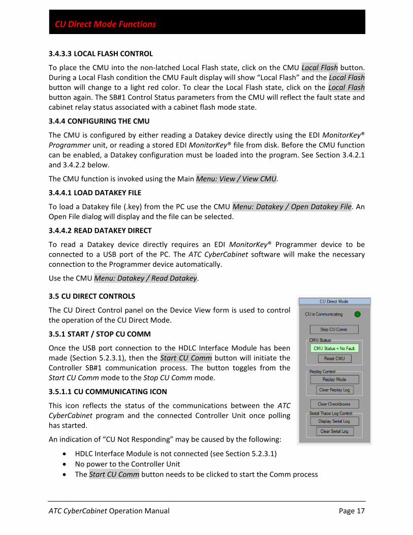
3.5 CU DIRECT CONTROLS
The CU Direct Control panel on the Device View form is used to control the operation of the CU Direct Mode.
3.5.1 START / STOP CU COMM
Once the USB port connection to the HDLC Interface Module has been made (Section 5.2.3.1), then the Start CU Comm button will initiate the Controller SB#1 communication process. The button toggles from the Start CU Comm mode to the Stop CU Comm mode.
3.5.1.1 CU COMMUNICATING ICON
This icon reflects the status of the communications between the ATC CyberCabinet program and the connected Controller Unit once polling has started.
An indication of “CU Not Responding” may be caused by the following:
• HDLC Interface Module is not connected (see Section 5.2.3.1) • No power to the Controller Unit • The Start CU Comm button needs to be clicked to start the Comm process
ATC CyberCabinet Operation Manual Page 18
CU Direct Mode Functions
3.5.2 CMU STATUS
This text box reports the fault status of the ATC CyberCabinet CMU (Section 6). If the CMU form is hidden from the main window, clicking this text box brings the CMU form to the front view.
3.5.3 RESET THE CMU
If the CMU has detected a fault condition, it can be reset to the No-Fault state by clicking the Reset CMU button.
3.5.4 REPLAY MODE
The Replay Mode button will load the Replay Mode control form (see Section 8). This temporarily suspends real-time operation and allows a replay of the past controller sequence.
3.5.5 CLEAR REPLAY LOG
The Clear Replay Log button will clear all records of the Replay Log (see Section 8). The Replay Log function will then start collecting records from that point.
3.5.6 DISPLAY SERIAL TRACE LOG
The Display Serial Log button will load the Serial Comm Trace Log form (see Section 9) and display the Command and Response frame records captured from the last SB#1 activity. The Max Serial Log Count parameter on the Settings form (Section 5.2.5) can be used to limit the length of the captured records.
3.5.7 CLEAR SERIAL TRACE LOG
The Clear Serial Log button will clear all records of the Serial Comm Trace Log (see Section 9). The Serial Comm Trace Log function will then start collecting records from that point.
3.5.8 CLEAR CHECKBOXES
If checkboxes have been manually set on the SIU Input form or SIU Output form, the Clear Checkboxes button will clear them all.

ATC CyberCabinet Operation Manual Page 19
SIU Direct Mode Functions
Section 4 SIU Direct Mode Functions
4.1 GENERAL
The SIU Direct mode is used to communicate directly to a hardware SIU-2218 installed in a physical ATC cabinet. Using the ATC CyberCabinet SIU input and output forms of this mode, a user can monitor the SIU IO responses to CU commands. The SIU Direct mode also allows the user to bypass the CU Serial Bus #1 commands and set inputs and outputs of the target SIU directly from the form. This mode can be helpful to trouble shoot problems with a suspect SIU-2218, or to exercise an Input or Output Assembly directly without a CU installed.
4.2 SERIAL CONNECTION TO THE TARGET SIU-2218
The front panel serial port of the SIU-2218 is a 9 pin metal shell “DB9S” female subminiature type connector. Because the port is configured as a DTE device, it requires a Null Modem connection to a PC serial port. If the PC does not provide a serial port, many Serial to USB adaptors are available. The USB adaptor must be a either a Null Modem configuration or a Null Modem adaptor must be used.
4.2.1 SIU-2218 FRONT PANEL PORT
Pin # Function IO
1 Not Used - 2 Receive Data I 3 Transmit Data O 4 Not Used - 5 Signal Ground X 6 Not Used - 7 Not Used - Not Used -
9 Not Used -
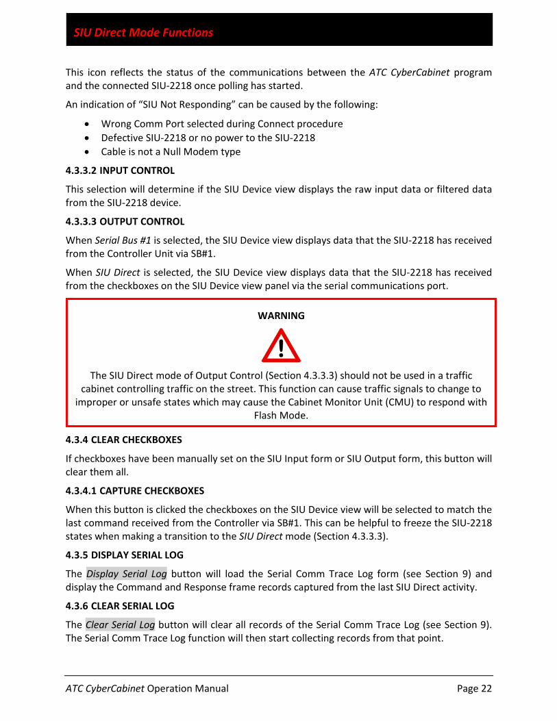
WARNING
The SIU Direct mode of Output Control (Section 4.3.3.3) should not be used in a traffic
cabinet controlling traffic on the street. This function can cause traffic signals to change to improper or unsafe states which may cause the Cabinet Monitor Unit (CMU) to respond with
Flash Mode.

ATC CyberCabinet Operation Manual Page 20
SIU Direct Mode Functions
4.3 SIU DIRECT MODE FUNCTIONALITY
The SIU Direct Mode of the ATC CyberCabinet program is selected with the Main Menu: Configuration / Operating mode / SIU Direct. The IO mapping will be set according to the cabinet type selected in the Main Menu: Configuration. See Section 10 for details on Cabinet Type Maps.
4.3.1 CONNECTING THE SERIAL PORT
Once the physical cable connection between the PC and SIU2218 is made, the PC Comm Port must be selected and opened. Use the Main Menu: Open Comm Port to open the Connection dialog form.
4.3.1.1 SCAN PORTS BUTTON
Click on the Scan Ports button to populate the pull-down menu with all available serial Comm ports of the PC. Select the Comm port entry of the pull-down menu item that corresponds to the serial port or USB adaptor port to the SIU. If the correct port is not known, the PC Device Manager may be helpful to identify the connection to a USB adaptor or direct cable.
4.3.1.2 CONNECT BUTTON
Once the Comm port has been selected in the pull-down menu item, this button will open the port and allow ATC CyberCabinet communications to the SIU-2218 device. The Port Connected Status will update if the connection is successful.
4.3.1.3 DISCONNECT BUTTON
To close the Comm port, click on the Disconnect button. This will release the selected Comm port back to Windows for other applications to use.
4.3.1.4 AUTOCONNECT ENABLE
If this box is checked then when launched, the ATC CyberCabinet program will try to open the same Comm port used in the previous session without having to invoke the Open Comm Port form. This setting can also be enabled or disabled in the Settings form, see Section 5.2.5.
4.3.1.5 CLOSE
The Close button will close the Connection dialog form.

ATC CyberCabinet Operation Manual Page 21
SIU Direct Mode Functions
4.3.2 SIU IO VIEWS
The SIU view will change between an Input SIU and Output SIU depending on the mode of the physical SIU-2218.
4.3.2.1 INPUT SIU
When linked to an Input SIU-2218, the blue circular indicators display that an input to the SIU is active. The associated checkbox can be checked to manually force the input to the active state when the Output Control radio button labeled SIU Direct is selected. See Section 4.3.3.3.
4.3.2.2 OUTPUT SIU
When linked to an Output SIU-2218, the colored signal indicators display that an output to the SIU is active. The associated checkbox can be checked to manually force the output to the active state when the Output Control radio button labeled SIU Direct is selected. See Section 4.3.3.3.
4.3.3 SIU DIRECT CONTROLS
The SIU Direct Control panel is used to control the operation of the SIU Direct Mode functions.
4.3.3.1 START POLL
Once the Comm port connection has been made, the Start Poll button will initiate the SIU-2218 polling process. The button toggles from the Start Poll mode to the Stop Poll mode.
4.3.3.1.1 SIU COMMUNICATING ICON
ATC CyberCabinet Operation Manual Page 22
SIU Direct Mode Functions
This icon reflects the status of the communications between the ATC CyberCabinet program and the connected SIU-2218 once polling has started.
An indication of “SIU Not Responding” can be caused by the following:
• Wrong Comm Port selected during Connect procedure • Defective SIU-2218 or no power to the SIU-2218 • Cable is not a Null Modem type
4.3.3.2 INPUT CONTROL
This selection will determine if the SIU Device view displays the raw input data or filtered data from the SIU-2218 device.
4.3.3.3 OUTPUT CONTROL
When Serial Bus #1 is selected, the SIU Device view displays data that the SIU-2218 has received from the Controller Unit via SB#1.
When SIU Direct is selected, the SIU Device view displays data that the SIU-2218 has received from the checkboxes on the SIU Device view panel via the serial communications port.
4.3.4 CLEAR CHECKBOXES
If checkboxes have been manually set on the SIU Input form or SIU Output form, this button will clear them all.
4.3.4.1 CAPTURE CHECKBOXES
When this button is clicked the checkboxes on the SIU Device view will be selected to match the last command received from the Controller via SB#1. This can be helpful to freeze the SIU-2218 states when making a transition to the SIU Direct mode (Section 4.3.3.3).
4.3.5 DISPLAY SERIAL LOG
The Display Serial Log button will load the Serial Comm Trace Log form (see Section 9) and display the Command and Response frame records captured from the last SIU Direct activity.
4.3.6 CLEAR SERIAL LOG
The Clear Serial Log button will clear all records of the Serial Comm Trace Log (see Section 9). The Serial Comm Trace Log function will then start collecting records from that point.
WARNING
The SIU Direct mode of Output Control (Section 4.3.3.3) should not be used in a traffic
cabinet controlling traffic on the street. This function can cause traffic signals to change to improper or unsafe states which may cause the Cabinet Monitor Unit (CMU) to respond with
Flash Mode.

ATC CyberCabinet Operation Manual Page 23
Main Menus
Section 5 Main Menus
5.1 MENU: FILE
5.1.1 PROJECT FILE
Project files contain all of the configuration information for an ATC CyberCabinet session, and have a filename extension of “PJT”. Before quitting a session, the Project file should be saved so that revisiting the session later does not require any repeated setup work.
5.1.1.1 OPEN PROJECT FILE
Use the Main Menu: File / Open Project File to bring up an Open File dialog. Select the Project file for the session. The Default Directory setting is used to browse directly to a directory of ATC CyberCabinet projects. See Section 5.2.5.
The most recent five Project File entries are listed on the File menu for quick Open access.
5.1.1.2 SAVE PROJECT FILE
Use the Main Menu: File / Save Project File to bring up a Save File dialog. Select the Project file name for the session. A backup copy is made of the previous project file (if it exists) and named with a “Backup of <filename>.pjt” filename prefix. The Default Directory setting is used to browse directly to a directory of ATC CyberCabinet projects. See Section 5.2.5.
5.1.2 EXIT
This menu option ends the ATC CyberCabinet program. If changes to the program setup or configuration have been made, the Project should be saved before exiting the program. See Section 5.1.1.2
5.2 MENU: CONFIGURATION
Main Menu: Configuration
5.2.1 CABINET TYPE
This menu option selects the type of ATC or 33x cabinet to be emulated. This defines the IO mapping used for the SIUs and FIO. Main Menu: Configuration / Cabinet Type
• ATC Cabinet: Uses standard IO mapping as defined by the ATC5301 Standard v02.02. See Section 10.2 for mapping assignments.
• ATCC IO Combo: Uses custom IO mapping to combine the functionality of Input and Output with one SIU. See Section 10.3 for mapping assignments.
• ATCC NYCDOT: Uses custom IO mapping as defined by the NYCDOT LPLVC Specification. See Section 10.4 for mapping assignments.
• LADOT 33x: Uses custom IO mapping as defined by the LADOT Specification. • TEES 33x: Uses standard IO mapping as defined by the CalTrans TEES Specification.

ATC CyberCabinet Operation Manual Page 24
Main Menus
5.2.2 OPERATING MODE
This menu item selects the operating mode, CU Direct or SIU Direct. Main Menu: Configuration / Operating Mode
• The CU Direct Mode is the primary mode of the ATC CyberCabinet software. It uses the HDLC Interface Module to communicate with an ATC Controller Unit.
• The SIU Direct Mode is provided as an additional tool to communicate directly with hardware SIU-2218 devices installed in an operating cabinet.
5.2.3 OPEN COMM PORT
This menu option facilitates connecting to the COMM port associated with the Operating mode selected in Section 5.2.2
5.2.3.1 CONNECT USB (CU DIRECT MODE)
In the CU Direct mode, the software will automatically connect with the HDLC Interface Module if it is connected to a valid USB port. If not, then the connection can be reestablished with this menu item once the USB port is connected. Main Menu: Configuration / Connect USB
5.2.3.2 CONNECT COMM (SIU DIRECT MODE)
In the SIU Direct mode, the software will automatically connect with the last PC COMM port used to communicate with an SIU-2218 if the Auto Connect option is checked in the Settings form (see Section 5.2.5). If not, then the connection can be reestablished with this menu item. Main Menu: Configuration / Connect COMM
See Section 4.3.1 for details.
5.2.4 SIU ENABLES
This menu option is used to configure the SIUs being emulated in the CU Direct Mode. Only SIUs that are enabled will provide a response frame to be transmitted back to the CU. Main Menu: Configuration / SIU Enables
5.2.5 SETTINGS
The Settings form provides parameters to customize the program operation. Main Menu: Configuration / Settings
• SIU Direct Mode Auto Connect

ATC CyberCabinet Operation Manual Page 25
Main Menus
o When operating in the SIU Direct mode (Section 1.3.2), a check will cause the program to try and reconnect with the PC COMM port that was last used to communicate with the SIU.
• Max Serial Log Count o This value limits the size of the Serial Log. Keeping the number of records low makes
accessing the log quicker. The parameter is limited to 9999 records. • Default Project Directory
o This directory is used as the default path when opening or saving Project files, Datakey files, and Map files.
• SIU Input & Output Device View Format (ATCC Mode Only) o The SIU Device view can display each Input SIU in two formats; SIU Device or
Detector Device. o The SIU Device view can display each Output SIU with or without the Misc IO icons.
• Timestamp Format o Display the Time as 12 Hour AM/PM or 24 Hour format.
• Controller Time Offset Threshold o If the Controller date and time is offset from the PC time greater than the Controller
Time Offset Threshold value, then the CU Time status panel on the main form is shaded pink, and the offset in seconds is displayed.
• Background Mode o A Light or Dark setting is provide to adjust the brightness of the Device View and
Map View forms.
ATC CyberCabinet Operation Manual Page 26
Main Menus
5.3 MENU: VIEW
5.3.1 VIEW CMU
This menu option will launch the CMU function. The CMU form has its own menu structure, see Section 6.4. Main Menu: View / CMU. The proper CMU device type will be automatically selected based on the Cabinet Model.
5.3.2 INTERSECTION MAP VIEW
This menu option will launch the Map View function. The Map Editor form has its own menu structure, see Section 7.5. Main Menu: View / Map View
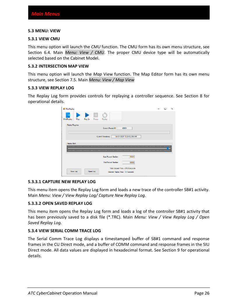
5.3.3 VIEW REPLAY LOG
The Replay Log form provides controls for replaying a controller sequence. See Section 8 for operational details.
5.3.3.1 CAPTURE NEW REPLAY LOG
This menu item opens the Replay Log form and loads a new trace of the controller SB#1 activity. Main Menu: View / View Replay Log/ Capture New Replay Log.
5.3.3.2 OPEN SAVED REPLAY LOG
This menu item opens the Replay Log form and loads a log of the controller SB#1 activity that has been previously saved to a disk file (*.TRC). Main Menu: View / View Replay Log / Open Saved Replay Log.
5.3.4 VIEW SERIAL COMM TRACE LOG
The Serial Comm Trace Log displays a timestamped buffer of SB#1 command and response frames in the CU Direct mode, and a buffer of COMM command and response frames in the SIU Direct mode. All data values are displayed in hexadecimal format. See Section 9 for operational details.

ATC CyberCabinet Operation Manual Page 27
Main Menus
5.3.4.1 CAPTURE NEW TRACE LOG
This menu item opens the Serial Comm Trace Log form and loads a new trace of the SB#1 activity. Main Menu: View / View Serial Comm Trace Log/ Capture New Trace Log
5.3.4.2 OPEN SAVED TRACE LOG
This menu item opens the Serial Comm Trace Log form and loads a log of the SB#1 activity that has been previously saved to a disk file (*.TRC). Main Menu: View / View Serial Comm Trace Log / Open Saved Trace Log
5.4 MENU: WINDOW
5.4.1 TILE
Once the SIU Enable settings are complete, the Tile function can order and display all of the SIU forms to be visible with some vertical scrolling required. Main Menu: Window / Tile.
5.4.2 CASCADE
Once the SIU Enable settings are complete, the Cascade function will order and display all of the SIU forms to be overlapped for a more condensed desktop view. Main Menu: Window / Cascade.
5.4.3 CENTER ALL WINDOWS
When loading a Project or Map file into a PC that has a different monitor screen setup, a form may load to a location not visible on the screen(s). For example, a project that uses two screens (left and right) is loaded into a PC with only one screen. Most cases are dealt with automatically, but the vast collection of screen configurations cannot always be anticipated.
If the main form is hidden, try the keystroke sequence while holding the <Alt> key with W then A. Main Menu: Window / Center All Windows.

ATC CyberCabinet Operation Manual Page 28
Main Menus
5.5 MENU: HELP
5.5.1 IO MAPS
This menu item displays a series of tables describing the mapping of SIU IO pins to ATC CyberCabinet functions. A table is presented for each of the four cabinet architectures currently supported. Main Menu: Help / IO Maps.
5.5.2 ABOUT
This menu item displays the ATC CyberCabinet software version information and the ATC CyberCabinet HDLC Interface Module version information. Main Menu: Help / About.
ATC CyberCabinet Operation Manual Page 29
Cabinet Monitor Unit (CMU)
Section 6 Cabinet Monitor Unit (CMU)
6.1 GENERAL
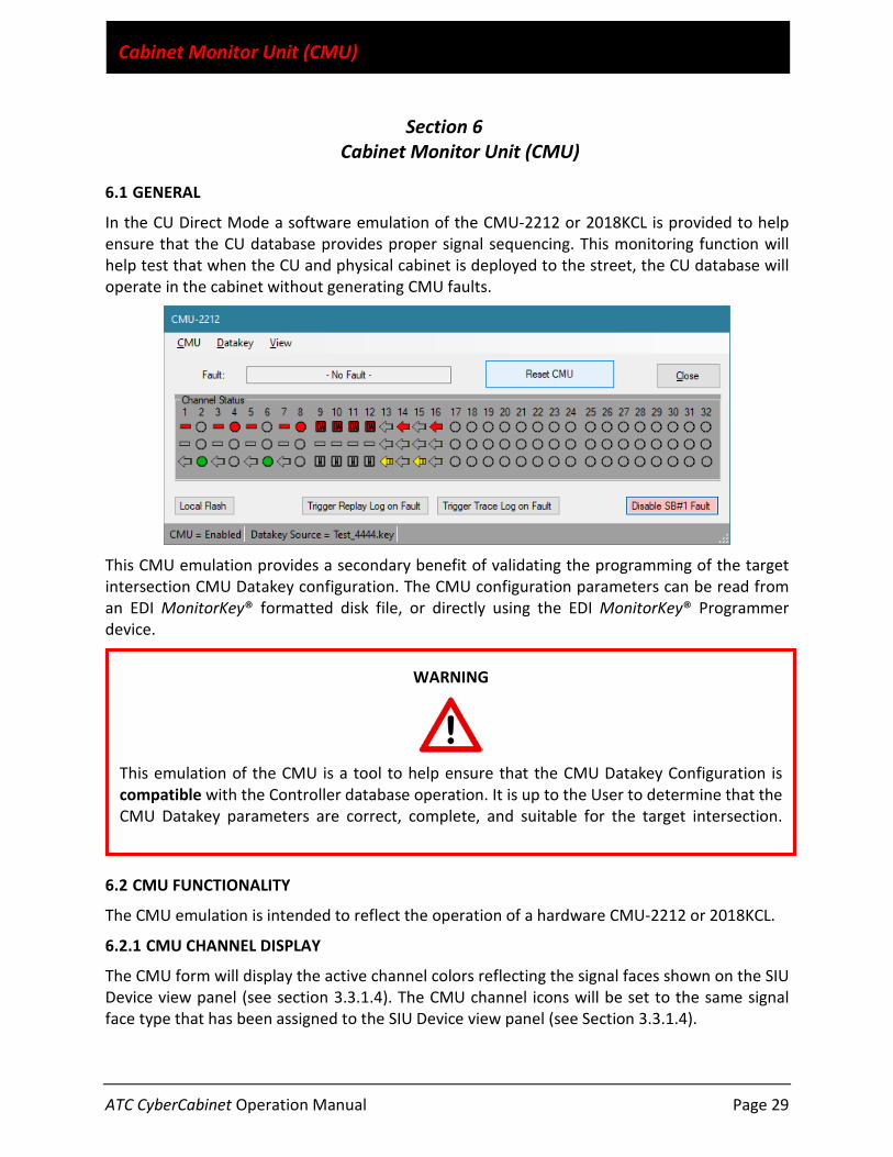
In the CU Direct Mode a software emulation of the CMU-2212 or 2018KCL is provided to help ensure that the CU database provides proper signal sequencing. This monitoring function will help test that when the CU and physical cabinet is deployed to the street, the CU database will operate in the cabinet without generating CMU faults.
This CMU emulation provides a secondary benefit of validating the programming of the target intersection CMU Datakey configuration. The CMU configuration parameters can be read from an EDI MonitorKey® formatted disk file, or directly using the EDI MonitorKey® Programmer device.
6.2 CMU FUNCTIONALITY
The CMU emulation is intended to reflect the operation of a hardware CMU-2212 or 2018KCL.
6.2.1 CMU CHANNEL DISPLAY
The CMU form will display the active channel colors reflecting the signal faces shown on the SIU Device view panel (see section 3.3.1.4). The CMU channel icons will be set to the same signal face type that has been assigned to the SIU Device view panel (see Section 3.3.1.4).
WARNING
This emulation of the CMU is a tool to help ensure that the CMU Datakey Configuration is compatible with the Controller database operation. It is up to the User to determine that the CMU Datakey parameters are correct, complete, and suitable for the target intersection.

ATC CyberCabinet Operation Manual Page 30
Cabinet Monitor Unit (CMU)
6.2.2 FAULT COVERAGE
The ATC CyberCabinet CMU monitoring functions include the following:
6.2.2.1 CONFLICT
Using the Permissive programming of the Datakey, the CMU will detect a Conflict fault when two or more non-compatible channels are active (Green or Yellow) for greater than 300 ms.
6.2.2.2 LACK OF SIGNAL (LOS) OR RED FAIL
The CMU will detect a Lack of Signal or Red Fail fault when all inputs of an enabled channel are not active for greater than 1250 ms.
6.2.2.2.1 DARK MAPS
The Lack of Signal monitoring function will be modified according to the current Dark Map selection provided by the CU in frame types 67, 81, or 83.
6.2.2.3 MULTIPLE SIGNAL
The CMU will detect a Multiple fault when two or more colors (G-Y, G-R, Y-R) of an enabled channel are active for more than 400 ms.
6.2.2.4 CLEARANCE
6.2.2.4.1 MINIMUM YELLOW CLEARANCE
The CMU will detect a Minimum Yellow Clearance fault when an enabled channel terminates the Green signal and activates the Red signal without displaying at least 2700 ms of Yellow.
6.2.2.4.2 MINIMUM YELLOW + RED CLEARANCE
The CMU will detect a Minimum Yellow+Red Clearance fault when an enabled channel terminates the Green signal and a conflicting Green signal is set active in less than 2700 ms.
6.2.2.5 FLASHING YELLOW ARROW
The CMU-2212 supports eight Flashing Yellow Arrow (FYA) 4-section signals. The 2018KCL supports four Flashing Yellow Arrow (FYA) 4-section signals.
6.2.2.5.1 FYA FLASH RATE
If enabled, the CMU will detect an FYA Flash Rate fault when the Overlap channel (Ra, sYa, fYa) flashing Yellow is active for more than 1500 ms.
6.2.2.5.2 FYA R&Y ENABLE
If enabled, the CMU will process the Red and Yellow inputs for Lack of Signal, Conflict, Multiple, and Clearance on an FYA Green Arrow channel. This applies only to the CMU-2212.
6.2.2.5.3 FYA YELLOW TRAP
If enabled, the CMU will detect an FYA Yellow Trap when the Overlap channel (Ra, sYa, fYa) solid Yellow is active and the Opposing thru phase Green is active. This applies only to the CMU-2212.

ATC CyberCabinet Operation Manual Page 31
Cabinet Monitor Unit (CMU)
6.2.2.6 VIRTUAL CHANNELS
Four Virtual Channels (Ch: 29, 30, 31, and 32) are supported. This applies only to the CMU-2212.
6.2.2.7 SERIAL BUS #1 TIMEOUT
If the SB#1 communication from the CU stops for more than 300 ms, the CMU will detect a SB#1 Timeout fault. This fault is non-latching for the first two times in a 24 hour period. The third event is latched and requires a Reset of the CMU. This applies only to the CMU-2212.
6.2.2.8 WDT TIMEOUT
If the SB#1 communication from the CU stops for more than 300 ms, the CMU will detect a SB#1 Timeout fault. This fault is non-latching for the first two times in a 24 hour period. The third event is latched and requires a Reset of the CMU. This applies only to the 2018KCL.
6.2.2.9 LOCAL FLASH INPUT
The Local Flash button provides a way to emulate the Local Flash (AUTO / FLASH) switch in a cabinet. This is a non-latched fault state.
6.3 OPERATING THE CMU
From the Main menu select Menu: View / CMU to open the CMU function. The CMU status (enabled and fault) is also shown on the CU Direct Mode Control panel. Clicking this status window will bring the CMU form to the front to see more detail if the CMU form is hidden behind other windows.
The CMU must have a Datakey configuration loaded before it can be enabled. See Section 6.4.1.1 and 6.4.1.2.
6.3.1 RESET CMU
The Reset CMU button is used to clear the fault state of the CMU once a fault has been detected.
6.3.2 LOCAL FLASH
The Local Flash button can be toggled On and Off to emulate the AUTO / FLASH switch found in a real cabinet. Local Flash is a non-latched fault.
6.3.3 DISABLE SB#1 FAULT
The SB#1 Timeout fault can be disabled if stopping the Controller communications to the HDLC Interface Module will occur as part of the testing process. This allows the Controller sequence to continue without the “Exit From Flash” process.
6.3.4 TRIGGER REPLAY LOG ON FAULT
When this mode is enabled by clicking the Trigger Replay Log on Fault button, the Replay Trace Log (Section 8) will be captured when the CMU detects a fault condition.

ATC CyberCabinet Operation Manual Page 32
Cabinet Monitor Unit (CMU)
6.3.5 TRIGGER TRACE LOG ON FAULT
When this mode is enabled by clicking the Trigger Trace Log on Fault button, the Serial Comm Trace Log (Section 9) will be captured when the CMU detects a fault condition.
6.4 CMU MENU ITEMS
6.4.1 CMU MENU
6.4.1.1 ENABLE / DISABLE CMU
Once a Datakey configuration has been loaded, the CMU can be enabled for fault detection. If the CMU is not enabled, the CMU channel display will continue to display signal status, but no faults will be detected. CMU Menu: CMU / Enable (Disable) CMU.
6.4.1.2 CONFIGURE CMU LOGIC OUTPUTS
The CMU can be configured to interact with certain SIU/FIO inputs or outputs. CMU Menu: CMU / Configure Logic.
6.4.1.2.1 CMU RESET INPUT
Some ATC Cabinets may be wired to connect an SIU output pin to the CMU External Test Reset. This provides a method for the Controller to reset a fault condition in the CMU. To emulate this functionality, the CMU Reset Input function is configured with an Enable control and which IO pin of which SIU will be used for the connection.
6.4.1.2.2 CMU FLASH SENSE OUTPUT
The CMU can drive a configured SIU IO pin reflecting the cabinet flash state. To emulate this functionality, the CMU Flash Sense output function is configured with an Enable control and which IO pin of which SIU will be used for the CMU output. The polarity of the output can be set True or False for Flash Mode.
• MMU/CMU Flash Sense input ..........select Flash = True • Local Flash Sense input .....................select Flash = False
6.4.1.2.3 CMU STOP TIME OUTPUT
The CMU can drive a configured SIU IO pin reflecting the cabinet flash state. To emulate this functionality, the CMU Stop Time output function is configured with an Enable control and which IO pin of which SIU will be used for the CMU output. The polarity of the output can be set True or False for Flash Mode. This output is only for the 2018KCL CMU.
• CMU Stop Time input ........................select Flash = True
6.4.2 DATAKEY MENU
If a Datakey filename was saved in a previous session of the project, the Datakey file will be loaded into the CMU when the project file is opened. See section 5.1.1.1.
ATC CyberCabinet Operation Manual Page 33
Cabinet Monitor Unit (CMU)
6.4.2.1 OPEN DATAKEY FILE
This function will load a MonitorKey® formatted file from the PC disk containing the CMU Datakey parameters. The last five file names are displayed for easy access. CMU Menu: Datakey / Open Datakey File.
6.4.2.2 READ DATAKEY
This function will load a MonitorKey® configuration directly from the EDI MonitorKey® Programmer with a Datakey inserted. The MonitorKey® Programmer is connected via a USB port on the PC. CMU Menu: Datakey / Read Datakey.
6.4.3 VIEW MENU
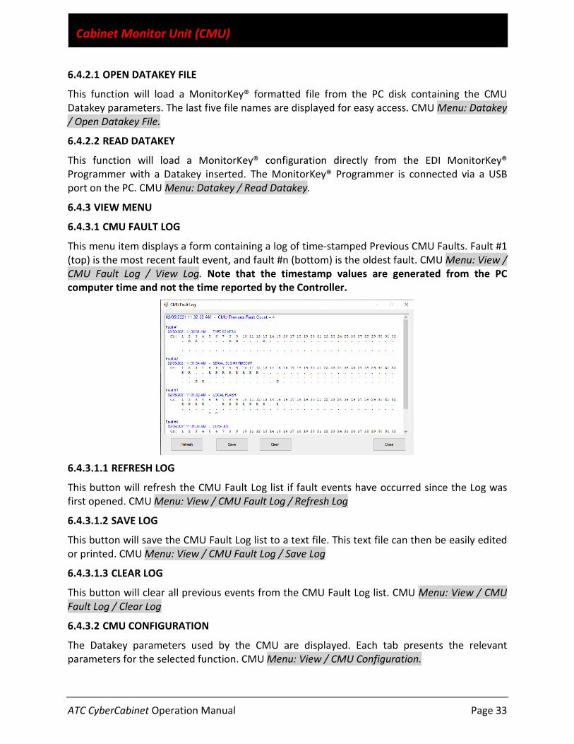
6.4.3.1 CMU FAULT LOG
This menu item displays a form containing a log of time-stamped Previous CMU Faults. Fault #1 (top) is the most recent fault event, and fault #n (bottom) is the oldest fault. CMU Menu: View / CMU Fault Log / View Log. Note that the timestamp values are generated from the PC computer time and not the time reported by the Controller.
6.4.3.1.1 REFRESH LOG
This button will refresh the CMU Fault Log list if fault events have occurred since the Log was first opened. CMU Menu: View / CMU Fault Log / Refresh Log
6.4.3.1.2 SAVE LOG
This button will save the CMU Fault Log list to a text file. This text file can then be easily edited or printed. CMU Menu: View / CMU Fault Log / Save Log
6.4.3.1.3 CLEAR LOG
This button will clear all previous events from the CMU Fault Log list. CMU Menu: View / CMU Fault Log / Clear Log
6.4.3.2 CMU CONFIGURATION
The Datakey parameters used by the CMU are displayed. Each tab presents the relevant parameters for the selected function. CMU Menu: View / CMU Configuration.

ATC CyberCabinet Operation Manual Page 34
Cabinet Monitor Unit (CMU)
ATC CyberCabinet Operation Manual Page 35
Map Editor
Section 7 Map Editor
7.1 GENERAL
The Map View is a higher level view of the Device View operation and best visualizes the actual operation of the intersection. Using this view is optional, but it provides a much easier interface to the CU Detector inputs and Signal outputs. Using the Map Editor, a bird’s eye view of the actual intersection is created using individual road furniture icons such as lanes, dividers, cross-walks, etc. Active Detector control icons are used to input calls to the CU and active Signal icons are used to display the CU signal outputs.
7.2 MAP FILES
The Map Editor results are stored in a MAP file for each project. MAP files can be created for common intersection configurations and loaded as templates when a new project is started. Once a MAP is created, it should be saved to a file on the PC. See Section 7.2.2.
7.2.1 OPEN MAP FILE
Use Menu: File / Open Map File to open a Map file. A list of the last recent five MAP files is provided for the Open function. Opening a Map file will replace all of the current icons in the Map view.
7.2.1.1 OPEN MAP AS OVERLAY
A Map file can be loaded without clearing the current icons in the Map view using this menu option. This is helpful if the Map file is part of a template collection of Map approaches or other icon collections. Menu: File / Open Map As Overlay.
7.2.2 SAVE MAP FILE
Use MAP Menu: File / Save Map File to save a Map file. A backup copy is made of the previous Map file (if it exists) and named with a “Backup of <filename>.map” filename.
7.3 MAP ICONS
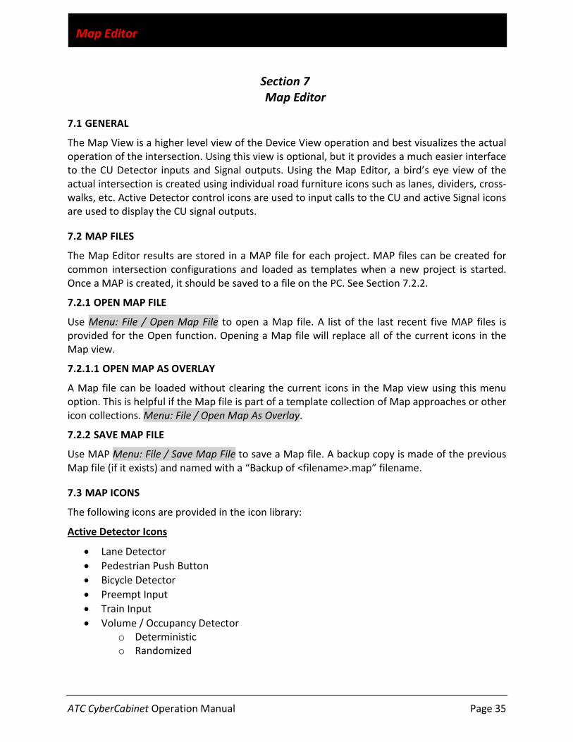
The following icons are provided in the icon library:
Active Detector Icons
• Lane Detector • Pedestrian Push Button • Bicycle Detector • Preempt Input • Train Input • Volume / Occupancy Detector
o Deterministic o Randomized

ATC CyberCabinet Operation Manual Page 36
Map Editor
Active Signal Icons
• Thru Ball • Protected Left Turn • Pedestrian Walk / Don’t Walk • Protected Right Turn • FYA Left Turn (4-section) • FYA Right Turn (4-section) • Permissive FYA Left Turn (3-section) • Permissive FYA Right Turn (3-section) • Protected-Permissive Left Turn (2-section) • Protected-Permissive Right Turn (2-section) • Transit (2-section) • Transit (3-section) • Bike (3-section) • Not Used (3-section) • Beacon (driven from Red output) • Beacon (driven from Yellow output) • Beacon (driven from Green output)
Lane Icons
• Unmarked Lane with no Stop Bar • Left Arrow Lane with Stop Bar • Right Arrow Lane with Stop Bar • Straight Arrow Lane with Stop Bar • Left Jog Lane • Bike Lane with Stop Bar • Bike Lane with no Stop Bar
Divider Icons
• Solid White • Dashed White • Single Yellow • Double Yellow • Ped Cross Walk • Rail Crossing
Paver Icons
• Rectangular Pavement
Label Icons
• 8 Point • 12 Point • 20 Point
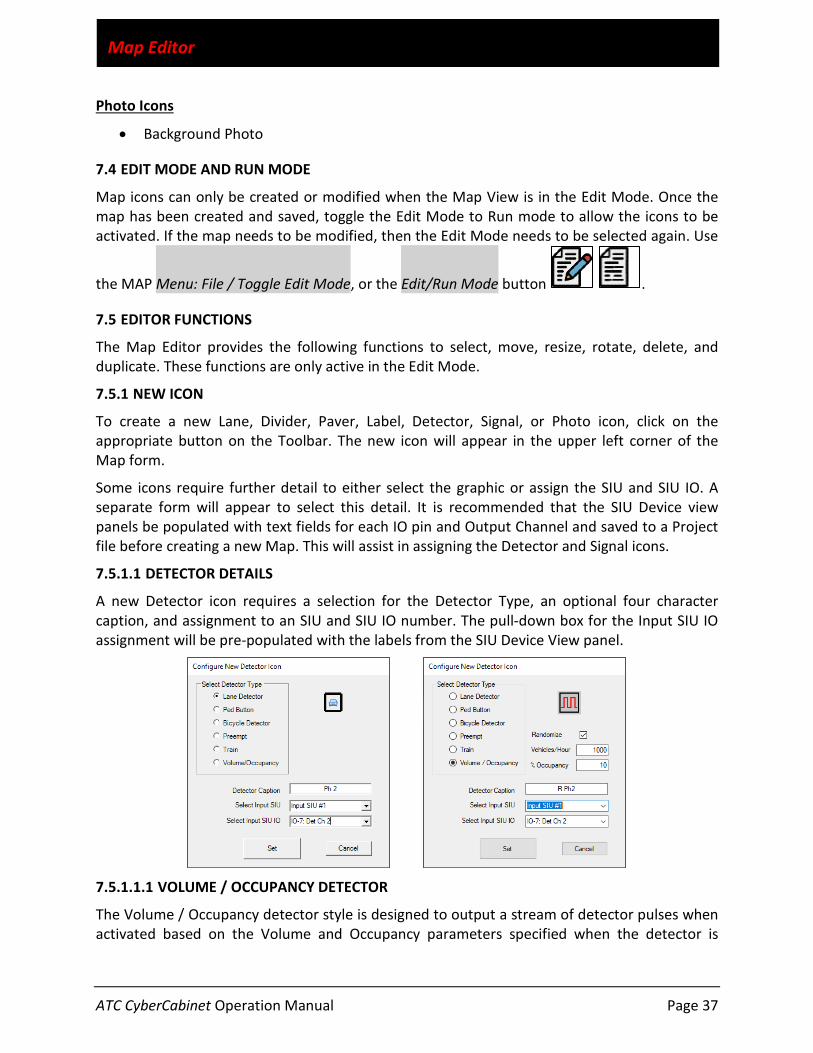
ATC CyberCabinet Operation Manual Page 37
Map Editor
Photo Icons
• Background Photo
7.4 EDIT MODE AND RUN MODE
Map icons can only be created or modified when the Map View is in the Edit Mode. Once the map has been created and saved, toggle the Edit Mode to Run mode to allow the icons to be activated. If the map needs to be modified, then the Edit Mode needs to be selected again. Use
the MAP Menu: File / Toggle Edit Mode, or the Edit/Run Mode button .
7.5 EDITOR FUNCTIONS
The Map Editor provides the following functions to select, move, resize, rotate, delete, and duplicate. These functions are only active in the Edit Mode.
7.5.1 NEW ICON
To create a new Lane, Divider, Paver, Label, Detector, Signal, or Photo icon, click on the appropriate button on the Toolbar. The new icon will appear in the upper left corner of the Map form.
Some icons require further detail to either select the graphic or assign the SIU and SIU IO. A separate form will appear to select this detail. It is recommended that the SIU Device view panels be populated with text fields for each IO pin and Output Channel and saved to a Project file before creating a new Map. This will assist in assigning the Detector and Signal icons.
7.5.1.1 DETECTOR DETAILS
A new Detector icon requires a selection for the Detector Type, an optional four character caption, and assignment to an SIU and SIU IO number. The pull-down box for the Input SIU IO assignment will be pre-populated with the labels from the SIU Device View panel.
7.5.1.1.1 VOLUME / OCCUPANCY DETECTOR
The Volume / Occupancy detector style is designed to output a stream of detector pulses when activated based on the Volume and Occupancy parameters specified when the detector is
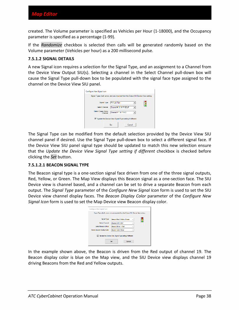
ATC CyberCabinet Operation Manual Page 38
Map Editor
created. The Volume parameter is specified as Vehicles per Hour (1-18000), and the Occupancy parameter is specified as a percentage (1-99).
If the Randomize checkbox is selected then calls will be generated randomly based on the Volume parameter (Vehicles per hour) as a 200 millisecond pulse.
7.5.1.2 SIGNAL DETAILS
A new Signal icon requires a selection for the Signal Type, and an assignment to a Channel from the Device View Output SIU(s). Selecting a channel in the Select Channel pull-down box will cause the Signal Type pull-down box to be populated with the signal face type assigned to the channel on the Device View SIU panel.
The Signal Type can be modified from the default selection provided by the Device View SIU channel panel if desired. Use the Signal Type pull-down box to select a different signal face. If the Device View SIU panel signal type should be updated to match this new selection ensure that the Update the Device View Signal Type setting if different checkbox is checked before clicking the Set button.
7.5.1.2.1 BEACON SIGNAL TYPE
The Beacon signal type is a one-section signal face driven from one of the three signal outputs, Red, Yellow, or Green. The Map View displays this Beacon signal as a one-section face. The SIU Device view is channel based, and a channel can be set to drive a separate Beacon from each output. The Signal Type parameter of the Configure New Signal Icon form is used to set the SIU Device view channel display faces. The Beacon Display Color parameter of the Configure New Signal Icon form is used to set the Map Device view Beacon display color.
In the example shown above, the Beacon is driven from the Red output of channel 19. The Beacon display color is blue on the Map view, and the SIU Device view displays channel 19 driving Beacons from the Red and Yellow outputs.
ATC CyberCabinet Operation Manual Page 39
Map Editor
7.5.1.3 INSPECTING DETECTOR AND SIGNAL ASSIGNMENTS
In either the Edit mode or Run mode, the Detector and Signal assignment parameters can be inspected by right clicking on the icon. This invokes a context menu that shows the details for each type of icon. Right-click View Detector Parameters or View Signal Parameter.
7.5.1.4 MODIFYING DETECTOR AND SIGNAL ASSIGNMENTS
In the Edit Mode, the Detector and Signal assignment parameters can be modified by right clicking on the icon. This invokes a context menu that shows the details for each type of icon. Right-click Modify Detector Parameters or Modify Signal Parameter
7.5.2 SELECT
When an icon is created or clicked with the mouse, it will be selected and display a red border around the icon. This selects the icon for other operations below. To de-select an icon, click on the selected icon again, click on the map background, or click on another icon. Multiple icons can be selected by holding the keyboard Ctrl key and clicking a series of icons. All icons can be selected by pressing the Ctrl key and the A key simultaneously.
7.5.2.1 PINNED ICONS
The Photo and Paver icons can be “Pinned” such that they cannot be selected. This prevents them from being accidentally selected and moved. To Pin or Unpin a Photo or Paver icon, right click the icon and click the Pinned menu item.
7.5.3 MOVE
To move an icon, it can be either selected or not selected. Press and hold the left mouse key over the icon and drag it to a new position, then release the left button. Icons will snap to a grid to assist in alignment. To move multiple icons they all need to be selected.
7.5.4 RESIZE
The Lane, Divider, Paver, and Photo icons are allowed to be resized. Select the icon by clicking on it to display the red border. When the mouse is approaching the icon red border edge that can be resized, the mouse will change to a double arrow ( ) to indicate the direction of the resize. Press the left mouse button and drag the red border to the new width or height, then release the left button.
Resizing a Photo icon will maintain the original aspect ratio.
7.5.5 ROTATE
To rotate an icon it must be selected. If multiple icons are selected they will all be rotated. Click
on the Rotate button to rotate the icon 90 degrees. If multiple icons have been selected to rotate, they are rotated around the index point (left, top) of the first icon selected. If Ctl-A is used to select all icons, then the index point is the center of the MAP form.

ATC CyberCabinet Operation Manual Page 40
Map Editor
7.5.6 DELETE
To delete an icon it must be selected. If multiple icons are selected they will all be deleted. Click
on the Delete button , or the keyboard Del key to delete the selected icon(s).
7.5.7 DUPLICATE
To duplicate an icon it must be selected. If multiple icons are selected they will all be
duplicated. Click on the Duplicate button to duplicate the selected icon(s).
7.5.8 SEND TO FRONT
Detector, Signal, and Label icons should be displayed on a layer above the road furniture. Select
the icon and click on the Send Front button to move an icon to the upper layer.
7.5.9 SEND TO BACK
Most road furniture icons should be displayed in a layer below the active icons such as
detectors or signals. Select the icon and click on the Send Back button to move an icon to the lower layer.

ATC CyberCabinet Operation Manual Page 41
Replay Log
Section 8 Replay Mode
8.1 GENERAL The Replay Log function can be used to replay and review the past sequence of controller movements. The Replay log is limited to 100,000 records which ranges from five to ten minutes of operation depending on SIU configurations. Note that the timestamp values are generated from the PC computer time and not the time reported by the Controller.
8.2 CAPTURING THE REPLAY TRACE LOG
The Replay Trace Log can be captured by clicking the Replay Mode button on the Device View Control panel (Section 3.5.4) or using the CMU Trigger Replay Log on Fault function (Section 6.3.4).
8.2.1 SAVE LOG
The Save Log button will save a text version of the log to disk.
8.2.2 OPEN LOG
The Open Log button will load a previously saved Replay Trace Log into the form.
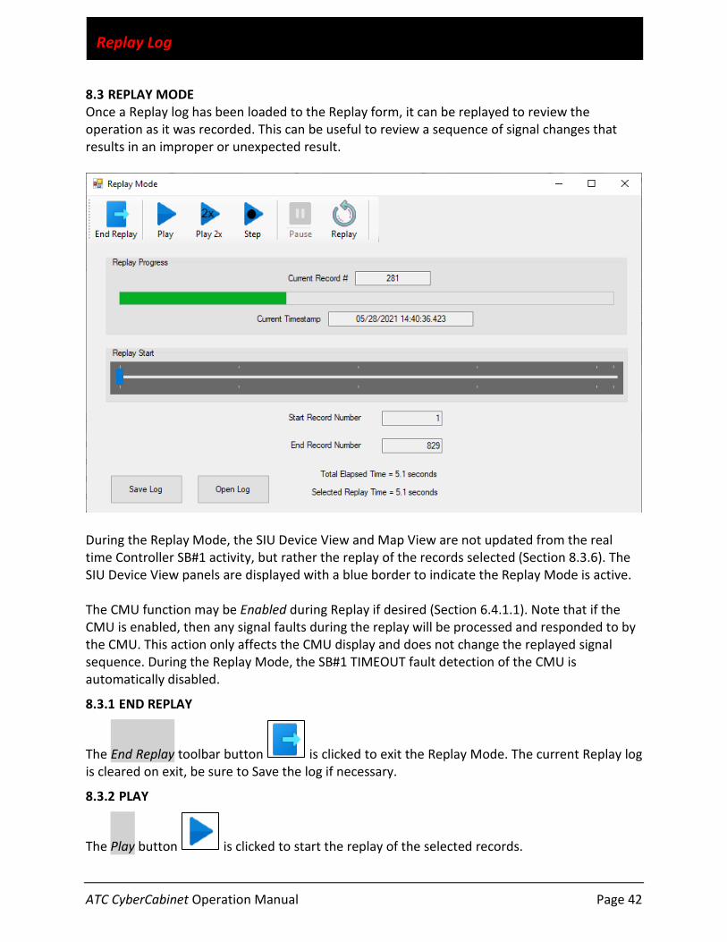
ATC CyberCabinet Operation Manual Page 42
Replay Log
8.3 REPLAY MODE Once a Replay log has been loaded to the Replay form, it can be replayed to review the operation as it was recorded. This can be useful to review a sequence of signal changes that results in an improper or unexpected result.
During the Replay Mode, the SIU Device View and Map View are not updated from the real time Controller SB#1 activity, but rather the replay of the records selected (Section 8.3.6). The SIU Device View panels are displayed with a blue border to indicate the Replay Mode is active. The CMU function may be Enabled during Replay if desired (Section 6.4.1.1). Note that if the CMU is enabled, then any signal faults during the replay will be processed and responded to by the CMU. This action only affects the CMU display and does not change the replayed signal sequence. During the Replay Mode, the SB#1 TIMEOUT fault detection of the CMU is automatically disabled.
8.3.1 END REPLAY
The End Replay toolbar button is clicked to exit the Replay Mode. The current Replay log is cleared on exit, be sure to Save the log if necessary.
8.3.2 PLAY
The Play button is clicked to start the replay of the selected records.

ATC CyberCabinet Operation Manual Page 43
Replay Log
8.3.3 PLAY 2X
The Play2x button is clicked to start the replay of the selected records at 2x speed.
8.3.4 STEP
The Step button is clicked to move forward to the next SIU frame update and then pause.
8.3.5 PAUSE
The Pause button can be clicked to temporarily stop the replay sequence. Clicking the Play or Play2x button resumes from that point, or clicking the Replay button will restart at the first selected record.
8.3.6 REPLAY
Following the completion of the replay sequence, the Replay button can be used to reposition the current record to the original Start Record number. Clicking the Play button will start the sequence again.
8.3.7 REPLAY START
The Replay Start slider is used to select where the replay sequence will begin in the captured log. The slider can be reset to any point within the log and is positioned with the following methods:
• Manually slide the blue knob to a position in the log. • A mouse click on the slider bar will move the knob left or right by approximately 12
seconds. • The left or right keyboard arrow keys will move the knob approximately 1.5 seconds.
The Start Record Number, Current Record Number, and Current Timestamp parameters are updated with the new position.
8.3.8 REPLAY PROGRESS
The Replay Progress bar indicates the progress of the Repay operation once the Play button is activated. The Progress Bar is scaled to the selected replay time.
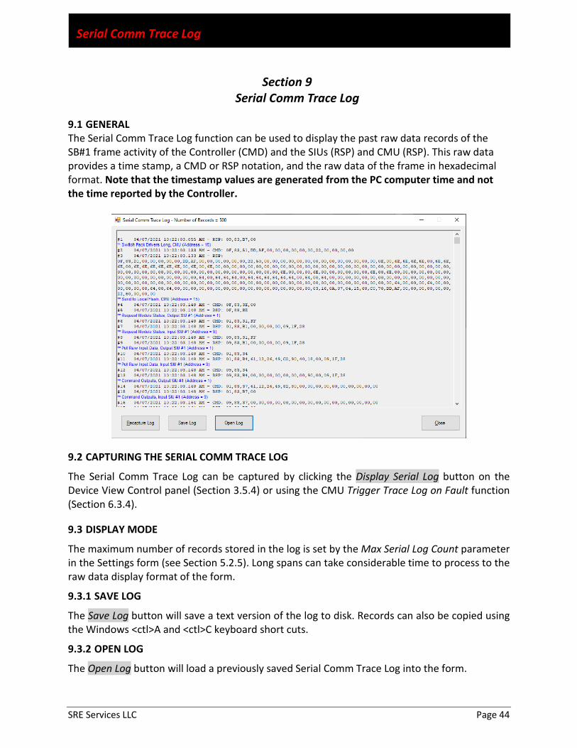
SRE Services LLC Page 44
Serial Comm Trace Log
Section 9 Serial Comm Trace Log
9.1 GENERAL The Serial Comm Trace Log function can be used to display the past raw data records of the SB#1 frame activity of the Controller (CMD) and the SIUs (RSP) and CMU (RSP). This raw data provides a time stamp, a CMD or RSP notation, and the raw data of the frame in hexadecimal format. Note that the timestamp values are generated from the PC computer time and not the time reported by the Controller.
9.2 CAPTURING THE SERIAL COMM TRACE LOG
The Serial Comm Trace Log can be captured by clicking the Display Serial Log button on the Device View Control panel (Section 3.5.4) or using the CMU Trigger Trace Log on Fault function (Section 6.3.4).
9.3 DISPLAY MODE
The maximum number of records stored in the log is set by the Max Serial Log Count parameter in the Settings form (see Section 5.2.5). Long spans can take considerable time to process to the raw data display format of the form.
9.3.1 SAVE LOG
The Save Log button will save a text version of the log to disk. Records can also be copied using the Windows <ctl>A and <ctl>C keyboard short cuts.
9.3.2 OPEN LOG
The Open Log button will load a previously saved Serial Comm Trace Log into the form.

SRE Services LLC Page 45
SIU IO Maps
Section 10 SIU IO Maps
10.1 GENERAL
This section details the IO mapping of the input and output SIUs for each cabinet type.
10.2 ATC CABINET
10.2.1 INPUT SIU
10.2.2 OUTPUT SIU

SRE Services LLC Page 46
SIU IO Maps
10.3 IO COMBO (BACKPACK)
<Future>
10.4 NYCDOT LPLVC CABINET

SRE Services LLC Page 47
SIU IO Maps
10.5 LADOT 332 CABINET
10.5.1 INPUT
10.5.2 OUTPUT
10.6 TEES 332 CABINET
10.6.1 OUTPUT

SRE Services LLC Page 48
SIU IO Maps
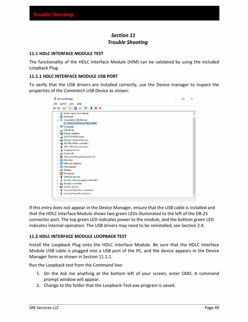
SRE Services LLC Page 49
Trouble Shooting
Section 11 Trouble Shooting
11.1 HDLC INTERFACE MODULE TEST
The functionality of the HDLC Interface Module (HIM) can be validated by using the included Loopback Plug.
11.1.1 HDLC INTERFACE MODULE USB PORT
To verify that the USB drivers are installed correctly, use the Device manager to inspect the properties of the Commtech USB Device as shown:
If this entry does not appear in the Device Manager, ensure that the USB cable is installed and that the HDLC Interface Module shows two green LEDs illuminated to the left of the DB-25 connector port. The top green LED indicates power to the module, and the bottom green LED indicates internal operation. The USB drivers may need to be reinstalled, see Section 2.4.
11.2 HDLC INTERFACE MODULE LOOPBACK TEST
Install the Loopback Plug onto the HDLC Interface Module. Be sure that the HDLC Interface Module USB cable is plugged into a USB port of the PC, and the device appears in the Device Manager form as shown in Section 11.1.1.
Run the Loopback test from the Command line:
1. On the Ask me anything at the bottom left of your screen, enter CMD. A command prompt window will appear.
2. Change to the folder that the Loopback-Test.exe program is saved.
SRE Services LLC Page 50
Trouble Shooting
3. Enter DIR. You should see a file named Loopback-Test.exe 4. If the USB port location is 0, Enter: Loopback-Test 0 5. The following will be displayed: TESTING, PLEASE WAIT 6. Check the status LEDs on the HDLC Interface Module while the test is running. If the
module is working correctly then the program reports: TEST COMPLETE AND 0 ERRORS is displayed.
7. Enter EXIT to go back to Windows
11.3 HDLC INTERFACE MODULE WARRANTY
The HDLC Interface Module hardware product is covered by a limited five (5) year warranty against defects in workmanship. This warranty is available only to the original Customer and only covers defects in our workmanship. Any HDLC Interface Module or harness assembly that is returned to SRE Services LLC will, at the option of SRE Services LLC, be repaired or replaced at no charge — except for circumstances excluded by this warranty.
A Return Materials Authorization (RMA) must be obtained from SRE Services LLC before a return will be accepted. The Customer is responsible for shipping charges when they return a HDLC Interface Module to SRE Services LLC. SRE Services LLC will pay the shipping charges to send the module back to the Customer if a defect in workmanship is found. However, if no defect in workmanship is found, or the module is not found to be defective, or any of the following warranty exclusions occur, the Customer will be responsible for shipping charges both ways.
Warranty Exclusions:
This warranty does not cover problems or damage resulting from, but not limited to the following:
• Any modification, misuse, abuse, disassembly, misapplication, or unauthorized repair by anyone other than SRE Services LLC.
• Any improper operation, including any use not in accordance with any verbal product instructions or documentation.
• Connection to an improper voltage supply or ESD damage. • Any other cause not related to workmanship.
11.4 TECHNICAL SUPPORT
Further technical support may be obtained by contacting SRE Services LLC. Email: [email protected] Web site: www.SreServicesLLC.com