atami standard operating procedure lpkf microline 2820p
TRANSCRIPT
LPKF Microline 2820P Laser Cutter - SOP
Page 1 of 23 (back to contents)
ATAMI Standard Operating Procedure
LPKF Microline 2820P Laser Cutter
Last saved by Randy Greb on 6/21/2019 4:10 PM
Revision Date Description/Change Curator
0 May 14, 2019 New document Randy Greb
1 June 19, 2019 Added additional information about DXF
file conversions and Tool library setups.
Randy Greb
2 August 21,
2019
Added recipe example, added notes
regarding sample thickness, cleaned up
some formatting.
Randy Greb
3 11/4/2019 Updated contents to make it easier to
read. Added a procedure for making
parts that can translate to DXF files for
milling.
Randy Greb
LPKF Microline 2820P Laser Cutter - SOP
Page 2 of 23 (back to contents)
Contents (you can click on the title to go to the subject page)
Scope: ............................................................................................................................................................ 2
System Specifications:................................................................................................................................... 3
Safety ............................................................................................................................................................ 3
Training Requirements .................................................................................................................................. 4
Procedures .................................................................................................................................................... 4
Convert a Solidworks part to DXF for full cut-through: ............................................................................ 4
Use the Design Studio Workstation to convert DXF to LMD format for use on LPKF: ............................. 5
How to Load a Flat sheet in the laser: ...................................................................................................... 7
How to Process a Cut Through: ................................................................................................................. 8
Startup Procedure: .................................................................................................................................... 9
Shutdown/standby Procedure: ............................................................................................................... 11
How to Edit Tool Libraries: ...................................................................................................................... 11
How to Use Solidworks to create a DXF file for milling: ......................................................................... 12
Standard or Example Recipes ..................................................................................................................... 15
Example of Recipe for cutting Stainless Steel Shims: ............................................................................. 15
Basic Troubleshooting ................................................................................................................................. 17
If you get startup errors or hear beeping from the system: ................................................................... 17
Hints for addressing laser burn quality issues: ....................................................................................... 18
Attachments ................................................................................................................................................ 19
LPKF User Interface button functions ..................................................................................................... 19
Health Hazards: ....................................................................................................................................... 21
Examples of what type of shape goes with which Modify Choice:......................................................... 22
Creating and Editing Tool Libraries: ........................................................................................................ 22
Information on Sample Size: ................................................................................................................... 22
Scope:
Operations of the laser including:
LPKF Microline 2820P Laser Cutter - SOP
Page 3 of 23 (back to contents)
How to prepare files
How to run standard recipes for cutting
How to update your specific recipes
Advanced applications such as circuit board cutting, via hole cutting, fiducial alignments.
System Specifications:
Please see the system description the ATAMI website for general specifications of this system.
Safety
General
Laser energies and pinch hazards are present in this sytem. Use extreme caution when opening and
closing the door and never defeat any laser interlocks.
PPE Required
Safety glasses
Nitrile gloves should always be used for handling and cleaning samples. Samples may have
contaminants as a result of the laser cutting.
Hazardous Energies
Electrical
Only ATAMI staff and qualified supplier maintenance personnel are allowed to open outside panels
and work on the system. All electrical hazard controls must be in place for maintenance. General
users are not allowed to open system panels.
Mechanical
Use caution when loading and unloading samples to avoid getting pinched.
Stored/Potential
Laser radiation is present in this system. Never operate the system without the front cover and all
other safety protections in place.
Thermal
Laser cutting may generate heat on the sample surface. Use caution when removing the sample
after cutting.
Direct exposure to laser radiation can cause burns.
Materials/Consumables Hazards
Use caution when removing cut samples. Always use nitrile gloves when handling cut samples.
LPKF Microline 2820P Laser Cutter - SOP
Page 4 of 23 (back to contents)
If appropriate use 100% IPA and a white Texwipe towel to clean the sample and the surface of
the vacuum stage after cutting.
Interlocks
Interlocks are in place to prevent exposure to laser radiation and the moving stage. Never
defeat interlocks.
Training Requirements
1. Pass all ATAMI required safety courses 2. Finish lab tour with qualified ATAMI trainer. 3. Complete all hands on training for this system and signed off by trainer. 4. Verify access to this document for reference.
Procedures
Convert a Solidworks part to DXF for full cut-through:
Step Action Notes
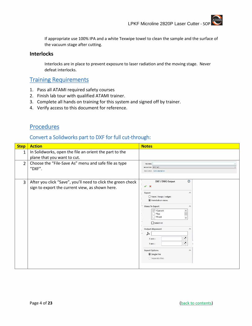
1 In Solidworks, open the file an orient the part to the plane that you want to cut.
2 Choose the “File-Save As” menu and safe file as type “DXF”.
3 After you click “Save”, you’ll need to click the green check sign to export the current view, as shown here.
LPKF Microline 2820P Laser Cutter - SOP
Page 5 of 23 (back to contents)
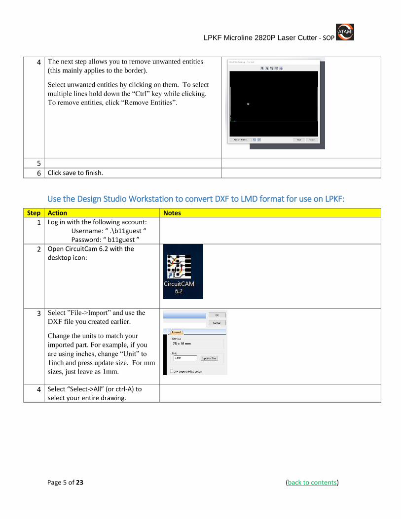
4 The next step allows you to remove unwanted entities
(this mainly applies to the border).
Select unwanted entities by clicking on them. To select
multiple lines hold down the “Ctrl” key while clicking.
To remove entities, click “Remove Entities”.
5
6 Click save to finish.
Use the Design Studio Workstation to convert DXF to LMD format for use on LPKF:
Step Action Notes
1 Log in with the following account: Username: “ .\b11guest “ Password: “ b11guest ”
2 Open CircuitCam 6.2 with the desktop icon:
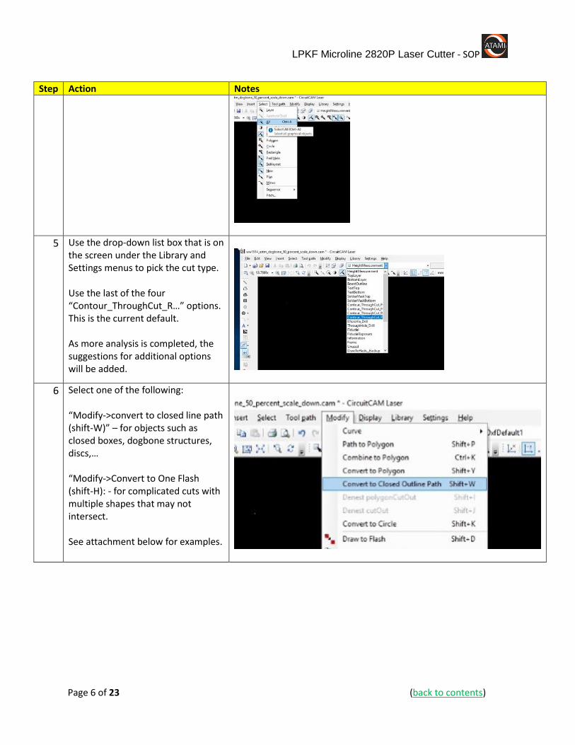
3 Select ”File->Import” and use the
DXF file you created earlier.
Change the units to match your
imported part. For example, if you
are using inches, change “Unit” to
1inch and press update size. For mm
sizes, just leave as 1mm.
4 Select “Select->All” (or ctrl-A) to select your entire drawing.
LPKF Microline 2820P Laser Cutter - SOP
Page 6 of 23 (back to contents)
Step Action Notes
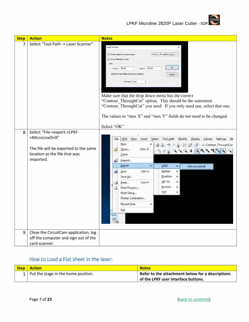
5 Use the drop-down list box that is on the screen under the Library and Settings menus to pick the cut type. Use the last of the four “Contour_ThroughCut_R…” options. This is the current default. As more analysis is completed, the suggestions for additional options will be added.
6 Select one of the following: “Modify->convert to closed line path (shift-W)” – for objects such as closed boxes, dogbone structures, discs,… “Modify->Convert to One Flash (shift-H): - for complicated cuts with multiple shapes that may not intersect. See attachment below for examples.
LPKF Microline 2820P Laser Cutter - SOP
Page 7 of 23 (back to contents)
Step Action Notes
7 Select “Tool Path -> Laser Scanner”
Make sure that the drop down menu has the correct
“Contour_ThroughCut” option. This should be the outermost
“Contour_ThroughCut” you used. If you only used one, select that one.
The values in “max X” and “max Y” fields do not need to be changed.
Select “OK”
8 Select “File->export->LPKF->MicroLineDrill” The file will be exported to the same location as the file that was imported.
9 Close the CircuitCam application, log off the computer and sign out of the card scanner.
How to Load a Flat sheet in the laser:
Step Action Notes
1 Put the stage in the home position. Refer to the attachment below for a descriptions of the LPKF user interface buttons.

LPKF Microline 2820P Laser Cutter - SOP
Page 8 of 23 (back to contents)
Step Action Notes
2 Turn on Vacuum and let the system sit for 30 seconds. This will clear any residual contaminants from the previous cuts.
3 Move the stage to the exchange position. Use caution, this will open the front door.
4 Wipe the vacuum surface with a Texwipe white towel and IPA to clean it of particles and contaminants.
This improves vacuum, prevents cross-contamination and
5 Place your sheet on the surface. If it does not cover the whole surface, you can use some of the plastic sheets to cover open areas and improve vacuum on your sample.
6 Turn on the vacuum and press the door button to close the door.
How to Process a Cut Through:
Step Action Notes
1 Select “File” “Import” “LMD/LPR…”
2 Select your file then click “Open”
3 Select “OK” at the Import message box.
4 From the menu bar, select “Job” “Material”
5 Enter the correct material thickness in “Thickness” and then press OK.
It is not required to edit other parameters for a cut through job. The defaults are sufficient.
6 From the menu bar, select “Job” “Tool Assignment…”
LPKF Microline 2820P Laser Cutter - SOP
Page 9 of 23 (back to contents)
Step Action Notes
7 Select the “Tool Library” you want to pick your tool from.
8 Select the “Tool Name” that you want to use.
9 Select the “Phase” that you want to use. If you have only one phase, leave the phase assignment as is. If you have multiple phases, the phase with the lower number will cut first.
10 Select “OK”
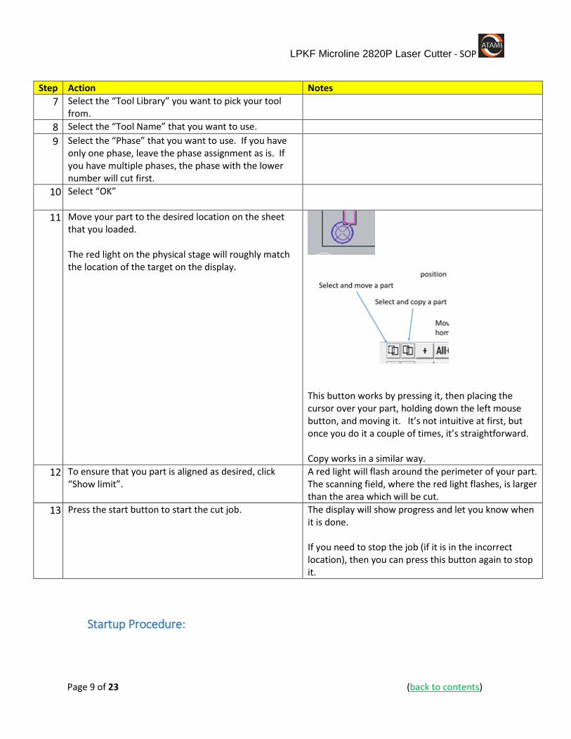
11 Move your part to the desired location on the sheet that you loaded. The red light on the physical stage will roughly match the location of the target on the display.
This button works by pressing it, then placing the cursor over your part, holding down the left mouse button, and moving it. It’s not intuitive at first, but once you do it a couple of times, it’s straightforward. Copy works in a similar way.
12 To ensure that you part is aligned as desired, click “Show limit”.
A red light will flash around the perimeter of your part. The scanning field, where the red light flashes, is larger than the area which will be cut.
13 Press the start button to start the cut job. The display will show progress and let you know when it is done. If you need to stop the job (if it is in the incorrect location), then you can press this button again to stop it.
Startup Procedure:
LPKF Microline 2820P Laser Cutter - SOP
Page 10 of 23 (back to contents)
Step Action Notes
1 If the system is powered down do the following:
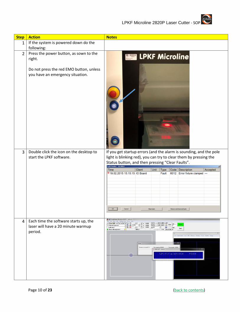
2 Press the power button, as sown to the right. Do not press the red EMO button, unless you have an emergency situation.
3 Double click the icon on the desktop to
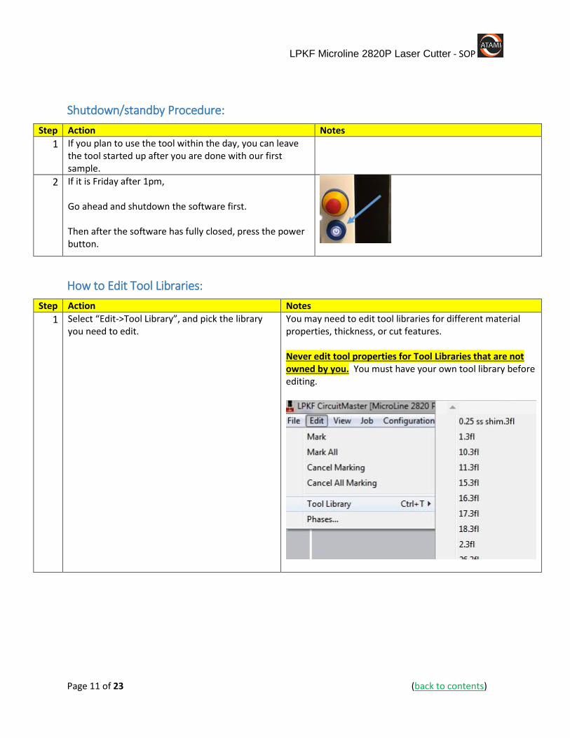
start the LPKF software. If you get startup errors (and the alarm is sounding, and the pole light is blinking red), you can try to clear them by pressing the Status button, and then pressing “Clear Faults”.
4 Each time the software starts up, the laser will have a 20 minute warmup period.
LPKF Microline 2820P Laser Cutter - SOP
Page 11 of 23 (back to contents)
Shutdown/standby Procedure:
Step Action Notes
1 If you plan to use the tool within the day, you can leave the tool started up after you are done with our first sample.
2 If it is Friday after 1pm, Go ahead and shutdown the software first. Then after the software has fully closed, press the power button.
How to Edit Tool Libraries:
Step Action Notes
1 Select “Edit->Tool Library”, and pick the library you need to edit.
You may need to edit tool libraries for different material properties, thickness, or cut features. Never edit tool properties for Tool Libraries that are not owned by you. You must have your own tool library before editing.
LPKF Microline 2820P Laser Cutter - SOP
Page 12 of 23 (back to contents)
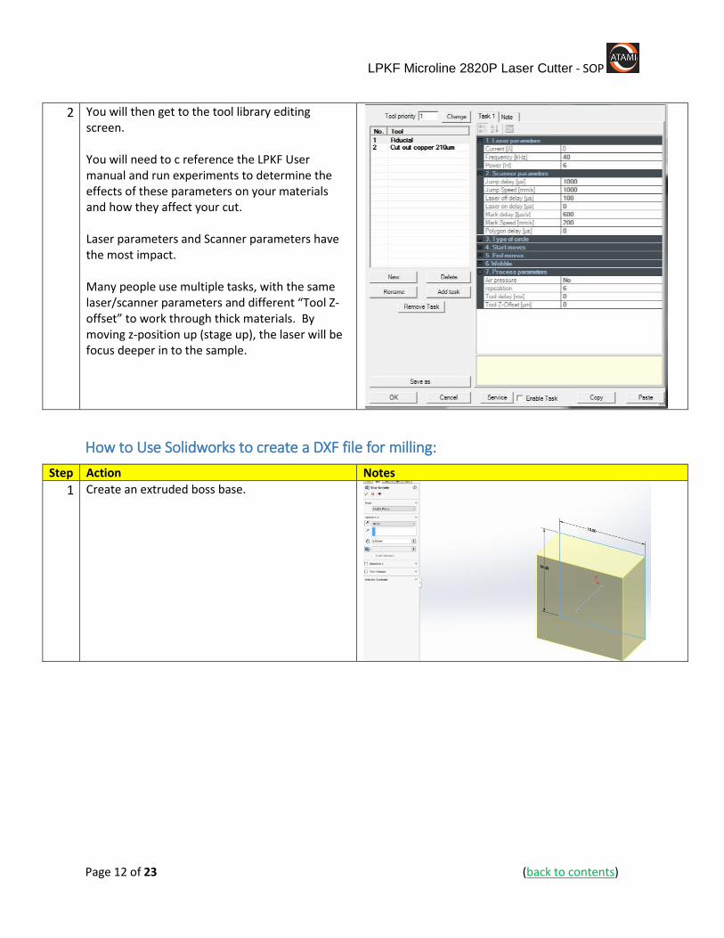
2 You will then get to the tool library editing screen. You will need to c reference the LPKF User manual and run experiments to determine the effects of these parameters on your materials and how they affect your cut. Laser parameters and Scanner parameters have the most impact. Many people use multiple tasks, with the same laser/scanner parameters and different “Tool Z-offset” to work through thick materials. By moving z-position up (stage up), the laser will be focus deeper in to the sample.
How to Use Solidworks to create a DXF file for milling:
Step Action Notes
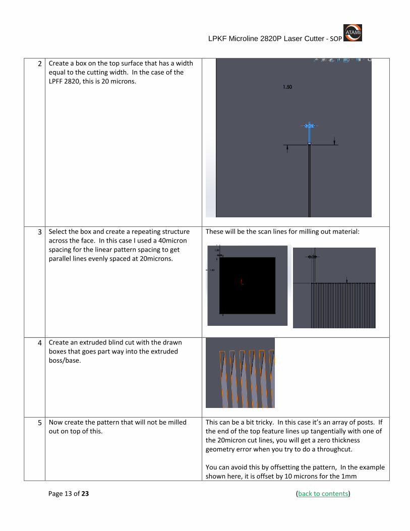
1 Create an extruded boss base.
LPKF Microline 2820P Laser Cutter - SOP
Page 13 of 23 (back to contents)
2 Create a box on the top surface that has a width equal to the cutting width. In the case of the LPFF 2820, this is 20 microns.
3 Select the box and create a repeating structure across the face. In this case I used a 40micron spacing for the linear pattern spacing to get parallel lines evenly spaced at 20microns.
These will be the scan lines for milling out material:
4 Create an extruded blind cut with the drawn boxes that goes part way into the extruded boss/base.
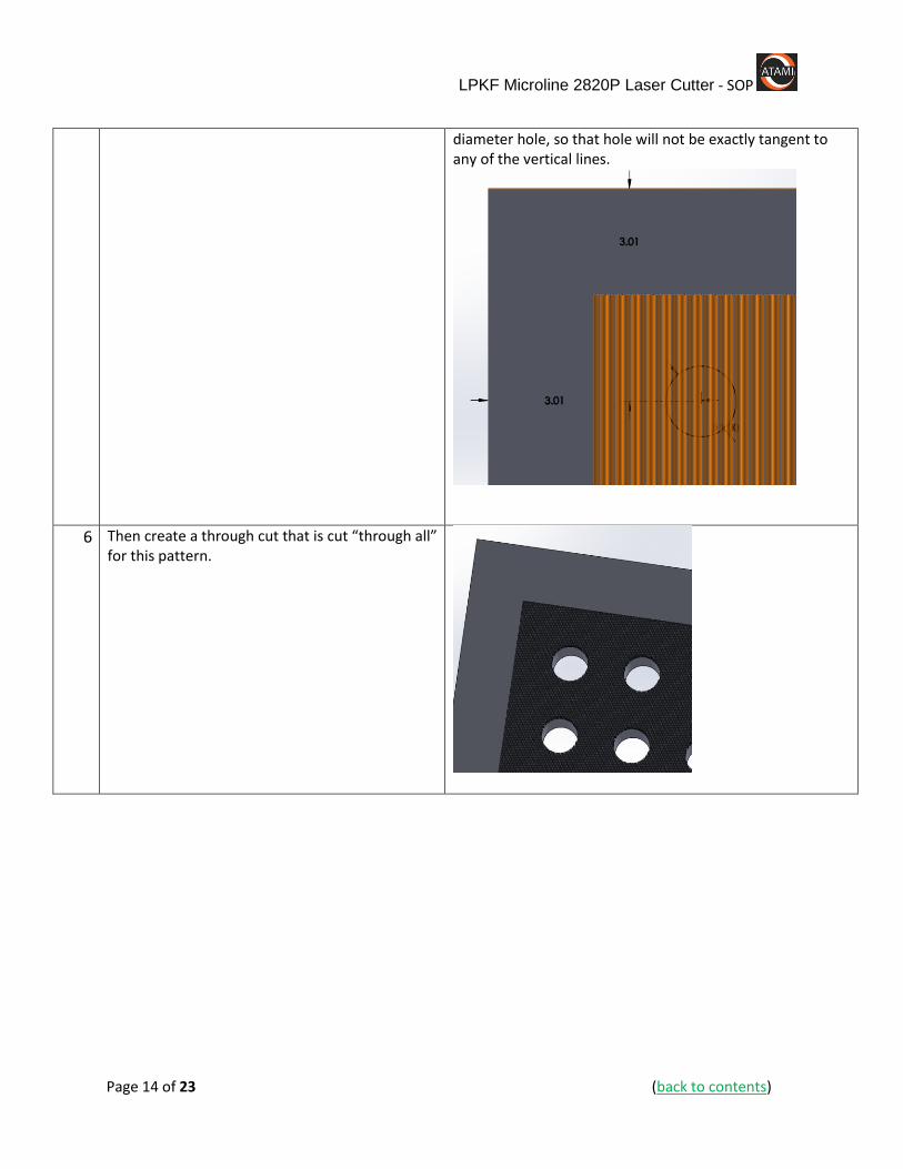
5 Now create the pattern that will not be milled out on top of this.
This can be a bit tricky. In this case it’s an array of posts. If the end of the top feature lines up tangentially with one of the 20micron cut lines, you will get a zero thickness geometry error when you try to do a throughcut. You can avoid this by offsetting the pattern, In the example shown here, it is offset by 10 microns for the 1mm
LPKF Microline 2820P Laser Cutter - SOP
Page 14 of 23 (back to contents)
diameter hole, so that hole will not be exactly tangent to any of the vertical lines.
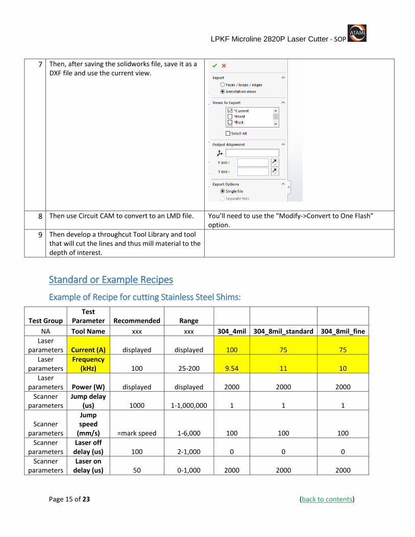
6 Then create a through cut that is cut “through all” for this pattern.
LPKF Microline 2820P Laser Cutter - SOP
Page 15 of 23 (back to contents)
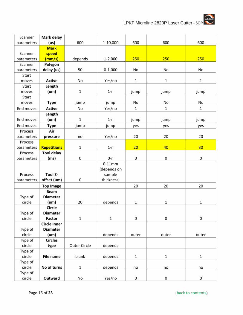
7 Then, after saving the solidworks file, save it as a DXF file and use the current view.
8 Then use Circuit CAM to convert to an LMD file. You’ll need to use the “Modify->Convert to One Flash” option.
9 Then develop a throughcut Tool Library and tool that will cut the lines and thus mill material to the depth of interest.
Standard or Example Recipes
Example of Recipe for cutting Stainless Steel Shims:
Test Group Test
Parameter Recommended Range
NA Tool Name xxx xxx 304_4mil 304_8mil_standard 304_8mil_fine
Laser parameters Current (A) displayed displayed 100 75 75
Laser parameters
Frequency (kHz) 100 25-200 9.54 11 10
Laser parameters Power (W) displayed displayed 2000 2000 2000
Scanner parameters
Jump delay (us) 1000 1-1,000,000 1 1 1
Scanner parameters
Jump speed
(mm/s) =mark speed 1-6,000 100 100 100
Scanner parameters
Laser off delay (us) 100 2-1,000 0 0 0
Scanner parameters
Laser on delay (us) 50 0-1,000 2000 2000 2000
LPKF Microline 2820P Laser Cutter - SOP
Page 16 of 23 (back to contents)
Scanner parameters
Mark delay (us) 600 1-10,000 600 600 600
Scanner parameters
Mark speed
(mm/s) depends 1-2,000 250 250 250
Scanner parameters
Polygon delay (us) 50 0-1,000 No No No
Start moves Active No Yes/no 1 1 1
Start moves
Length (um) 1 1-n jump jump jump
Start moves Type jump jump No No No
End moves Active No Yes/no 1 1 1
End moves Length (um) 1 1-n jump jump jump
End moves Type jump jump yes yes yes
Process parameters
Air pressure no Yes/no 20 20 20
Process parameters Repetitions 1 1-n 20 40 30
Process parameters
Tool delay (ms) 0 0-n 0 0 0
Process parameters
Tool Z-offset (um) 0
0-11mm (depends on
sample thickness)
Top Image 20 20 20
Type of circle
Beam Diameter
(um) 20 depends 1 1 1
Type of circle
Circle Diameter
Factor 1 1 0 0 0
Type of circle
Circle Inner Diameter
(um) depends outer outer outer
Type of circle
Circles type Outer Circle depends
Type of circle File name blank depends 1 1 1
Type of circle No of turns 1 depends no no no
Type of circle Outward No Yes/no 0 0 0
LPKF Microline 2820P Laser Cutter - SOP
Page 17 of 23 (back to contents)
Type of circle
Overlap (um) 0 depends
Basic Troubleshooting
If you get startup errors or hear beeping from the system:
Step If Then Notes
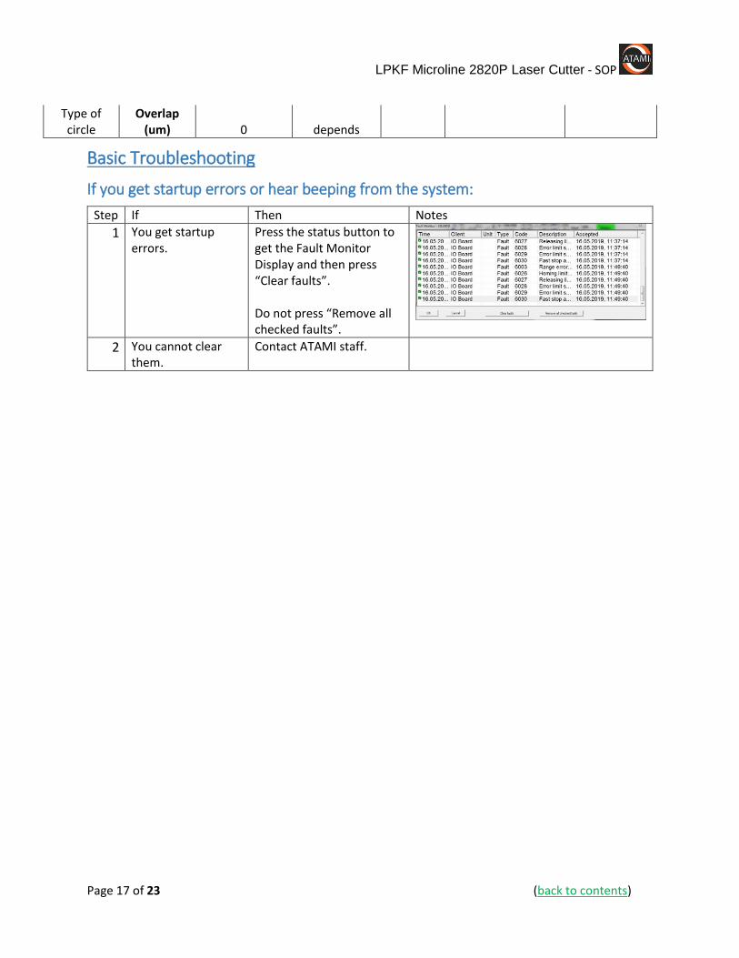
1 You get startup errors.
Press the status button to get the Fault Monitor Display and then press “Clear faults”. Do not press “Remove all checked faults”.
2 You cannot clear them.
Contact ATAMI staff.
LPKF Microline 2820P Laser Cutter - SOP
Page 18 of 23 (back to contents)
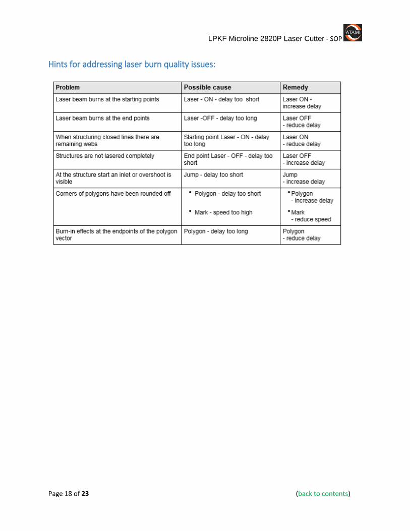
Hints for addressing laser burn quality issues:
LPKF Microline 2820P Laser Cutter - SOP
Page 19 of 23 (back to contents)
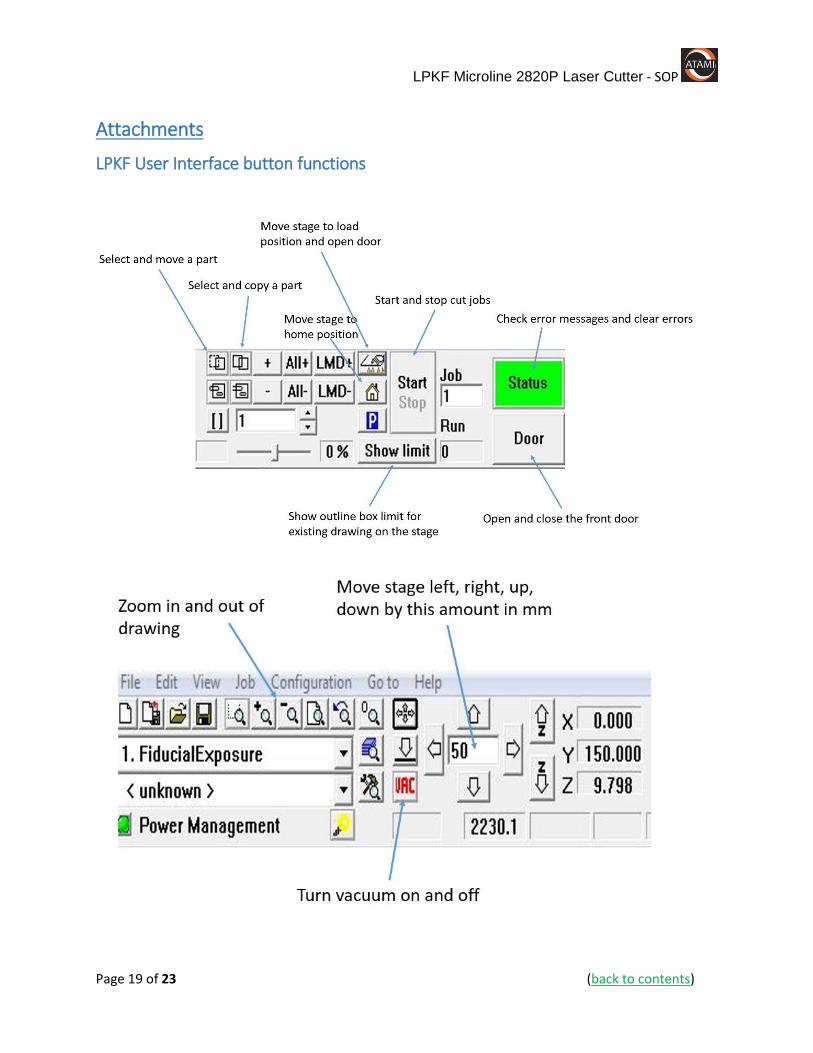
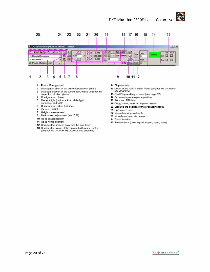
Attachments
LPKF User Interface button functions
LPKF Microline 2820P Laser Cutter - SOP
Page 20 of 23 (back to contents)

LPKF Microline 2820P Laser Cutter - SOP
Page 21 of 23 (back to contents)
Health Hazards:
LPKF Microline 2820P Laser Cutter - SOP
Page 22 of 23 (back to contents)
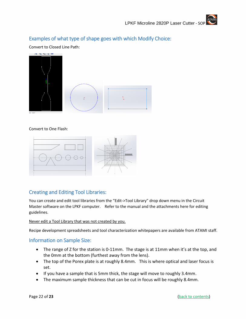
Examples of what type of shape goes with which Modify Choice:
Convert to Closed Line Path:
Convert to One Flash:
Creating and Editing Tool Libraries:
You can create and edit tool libraries from the “Edit->Tool Library” drop down menu in the Circuit
Master software on the LPKF computer. Refer to the manual and the attachments here for editing
guidelines.
Never edit a Tool Library that was not created by you.
Recipe development spreadsheets and tool characterization whitepapers are available from ATAMI staff.
Information on Sample Size:
The range of Z for the station is 0-11mm. The stage is at 11mm when it’s at the top, and the 0mm at the bottom (furthest away from the lens).
The top of the Porex plate is at roughly 8.4mm. This is where optical and laser focus is set.
If you have a sample that is 5mm thick, the stage will move to roughly 3.4mm.
The maximum sample thickness that can be cut in focus will be roughly 8.4mm.

LPKF Microline 2820P Laser Cutter - SOP
Page 23 of 23 (back to contents)
If you need to do cuts or marks on samples that are thicker than 8.4mm, then it will be out of focus, or we will need to develop a custom sample holder.