at & t nd-00071 rev 3 grounding standard
TRANSCRIPT
8/11/2019 At & t ND-00071 Rev 3 Grounding Standard
http://slidepdf.com/reader/full/at-t-nd-00071-rev-3-grounding-standard 1/177
AT&T Mobility Confidential and Proprietary Page 1 of 177
Use pursuant to Company instructions ©
2007 AT&T Mobility
AT&T Mobility Grounding Standard
Network Document: ND-00071 Rev. 2.0 08/27/07
Overview
This document provides This Standard provides engineering, material, and installation requirements forprotective grounding systems in structures containing network communications systems and otherequipment.
IMPORTANT: This document supports the following policy letter(s):
- PL-0028
Any changes to this document must go through the network document update process outlined athttp://ns.cingular.net/createpl.aspx prior to publishing to the Network Document Library.

8/11/2019 At & t ND-00071 Rev 3 Grounding Standard
http://slidepdf.com/reader/full/at-t-nd-00071-rev-3-grounding-standard 2/177

8/11/2019 At & t ND-00071 Rev 3 Grounding Standard
http://slidepdf.com/reader/full/at-t-nd-00071-rev-3-grounding-standard 3/177

8/11/2019 At & t ND-00071 Rev 3 Grounding Standard
http://slidepdf.com/reader/full/at-t-nd-00071-rev-3-grounding-standard 4/177
AT&T Mobilit y Grounding Standard
AT&T Mobility Confidential and Proprietary Page 4 of 177
Use pursuant to Company instructions ©
2007 AT&T Mobility
2.6.2 GWB at Power Plant with Insulated Return Bus .............................................................................. 55
2.6.3 GWB at Power Plant with Un-insulated Return Bus .........................................................................57
2.6.4 Sequencing.......................................................................................................................................57
2.6.5 Remote GWB.................................................................................................................................... 60
2.6.6 Relocating an Existing GWB ............................................................................................................61
2.7 Bonds to the Ground Window Bar.......................................................................................................62
2.7.1 Conduits, Raceways, and Other Conductive Paths .........................................................................62
2.8 Isolation of Communications Equipment.............................................................................................63
2.8.2 Lighting System Components........................................................................................................... 64
2.8.3 Foreign Object Bonds....................................................................................................................... 65
2.9 Isolated Bonding Network Equipment................................................................................................. 67
2.9.1 Isolated Ground Bar (IGB)................................................................................................................ 68
2.9.2 Isolated Ground Zone Restrictions...................................................................................................68
2.9.3 Framework Ground Systems............................................................................................................68
2.9.4 Logic Ground Systems .....................................................................................................................69
2.9.5 Battery Return Systems.................................................................................................................... 70
2.9.6 Equipment Separation and Circuit Location .....................................................................................70
2.9.7 Insulation ..........................................................................................................................................70
2.10 Power Plants .......................................................................................................................................71
2.10.2 Power Plant Location........................................................................................................................ 71
2.10.3 Power Plants Serving Common and Isolated Bonding Network Equipment .................................... 71
2.10.4 Different Isolated Bonding Networks Served by the Same Power Plant.......................................... 72
2.11 AC Equipment Grounding ................................................................................................................... 73
2.11.1 Feeder and Branch Circuit Equipment Grounding System .............................................................. 73
2.11.2 AC Power Distribution Cabinets ....................................................................................................... 75
2.11.3 AC Busduct System.......................................................................................................................... 75
2.11.4 Engine-Alternator Sets...................................................................................................................... 75
2.11.5 Grounding of AC Tap Boxes............................................................................................................. 77
2.11.6 Cord Connected AC Operated Equipment ....................................................................................... 77
2.11.7 Job Drawings, Architectural.............................................................................................................. 78
3. Power Plants and Equipment.............................................................................................................. 79
3.1 Scope .................................................................................................................................................. 79
3.2 General ................................................................................................................................................ 79
3.2.2 An Overview of Power and Grounding Systems .............................................................................. 79
3.2.3 DC Power Systems........................................................................................................................... 80

8/11/2019 At & t ND-00071 Rev 3 Grounding Standard
http://slidepdf.com/reader/full/at-t-nd-00071-rev-3-grounding-standard 5/177
AT&T Mobilit y Grounding Standard
AT&T Mobility Confidential and Proprietary Page 5 of 177
Use pursuant to Company instructions ©
2007 AT&T Mobility
3.2.4 Battery and Converter Plants, DC-DC Converters...........................................................................80
3.2.5 Power System Equipment Grounding .............................................................................................. 81
3.2.6 Engine Alternator Equipment............................................................................................................83
3.2.7 Power Distribution Systems..............................................................................................................84
3.2.8 Battery Distributing Fuse Board (BDFB)........................................................................................... 84
3.3 Transport, Information Technology and Miscellaneous Equipment....................................................86
3.3.1 Telecommunications Protection ....................................................................................................... 86
3.3.2 Incoming Service .............................................................................................................................. 86
3.3.3 Equipment Enclosure and Unit Requirements ................................................................................. 86
3.3.4 Lineup Conductors............................................................................................................................ 88
3.3.5 Supplemental Bonds to Ironwork and Other Metallic Objects .......................................................... 88
3.3.6 Other Systems.................................................................................................................................. 89
3.3.7 Bay Ground Lead.............................................................................................................................. 89
3.3.8 Conduits, Armored Cable, Shielded Wire for Other Than AC Service .............................................90
3.4 Distributing & Protector Frames.......................................................................................................... 90
3.5 Cable Entrance Facility (CEF).............................................................................................................91
3.6 Fiber Optic Cable Termination Equipment..........................................................................................91
3.7 Network Equipment on Raised Floors.................................................................................................92
3.7.1 General ............................................................................................................................................. 92
3.7.2 Horizontal Equalizer Conductor........................................................................................................ 92
3.7.3
Isolated Bonding Network Equipment .............................................................................................. 94
3.7.4 Common Bonding Network Equipment ............................................................................................94
3.7.5 Cable Rack Bonds............................................................................................................................ 94
4. Cell Sites and Equipment....................................................................................................................97
4.1 Scope .................................................................................................................................................. 97
4.2 General ................................................................................................................................................ 97
4.3 Exterior Cabinet Grounding Standard – General Requirements ........................................................98
4.4 Co-location Grounding Standard – General Requirements .............................................................. 100
4.4.2 Driven Ground System for Radio/Cell Sites ...................................................................................101
4.4.3 Tower Guy Wire (If Applicable)....................................................................................................... 105
4.5 Exterior Ring Ground System ...........................................................................................................105
4.5.1 Earth Electrode System.................................................................................................................. 105
4.5.2 Primary Bonds ................................................................................................................................106
4.5.3 Roof Ring Ground System..............................................................................................................106
4.5.4 Interior-Exterior Bonds....................................................................................................................109

8/11/2019 At & t ND-00071 Rev 3 Grounding Standard
http://slidepdf.com/reader/full/at-t-nd-00071-rev-3-grounding-standard 6/177
AT&T Mobilit y Grounding Standard
AT&T Mobility Confidential and Proprietary Page 6 of 177
Use pursuant to Company instructions ©
2007 AT&T Mobility
4.5.5 Bonds to Antenna Towers ..............................................................................................................109
4.6 Interior Ring Ground System.............................................................................................................109
4.6.2 Forming & Support of the Interior Ground Ring.............................................................................. 110
4.6.3 Conduit for Enclosing Ground Conductors..................................................................................... 111
4.6.4 Connections to the Interior Ground Ring........................................................................................ 112
4.6.5 Cell Reference Ground Bar ............................................................................................................113
4.6.6 IDENTIFICATION TAGS / LABELS................................................................................................ 114
4.6.7 Cell Reference Ground Bar Connections ....................................................................................... 114
4.6.8 Telco Ground Bar ........................................................................................................................... 122
Typical Grounding of Cell Site Fiber Optic Cable Detail ........................................................................... 123
4.6.9 Letter References: .......................................................................................................................... 123
4.7 Equipment Ground Wire.................................................................................................................... 124
4.7.1 Wire employed in the equipment grounding system, and extensions from there to frameworks,cabinets, and other units requiring equipment grounding shall be a minimum No. 6 AWG stranded
copper wire with green insulation. Aluminum conductors shall not be used in the equipment
grounding system. Bends of less than 8 inch radius shall be avoided. Bends greater than 90
degrees shall be avoided. Ground conductor sizes should be engineered to provide adequate fault
clearing capabilities. .......................................................................................................................124
4.8 Frame Bonding Requirements .......................................................................................................... 124
4.9 Miscellaneous Bonding .....................................................................................................................124
4.10 Incidental Conduit & Pipe Path Grounding........................................................................................126
4.11 PERIPHERAL/SUPPLEMENTARY CONDUCTOR SYSTEMS........................................................126
4.11.1 Peripheral Conductor...................................................................................................................... 126 4.11.2 Supplementary Conductors ............................................................................................................ 127
4.11.3 Waveguide and Coaxial Cable Bonds............................................................................................129
4.12 Unit bonds .........................................................................................................................................129
4.12.2 Exterior Unit Bonds......................................................................................................................... 129
4.12.3 Interior Unit Bonds.......................................................................................................................... 130
4.12.4 Frame/Cabinet Bonding Requirements ..........................................................................................131
4.12.5 Miscellaneous Unit Bonding ........................................................................................................... 131
4.12.6 Conduit, Pipe and Duct Bonding ....................................................................................................131
4.12.7 Bonding of Units outside the Ring Ground Periphery..................................................................... 132
4.13 Bonds at Structure Entrances ........................................................................................................... 132
4.13.1 General ...........................................................................................................................................132
4.13.2 Other Arrangements .......................................................................................................................133
4.13.3 Exterior Bonds ................................................................................................................................133
4.13.4 Interior Bonds .................................................................................................................................133

8/11/2019 At & t ND-00071 Rev 3 Grounding Standard
http://slidepdf.com/reader/full/at-t-nd-00071-rev-3-grounding-standard 7/177
AT&T Mobilit y Grounding Standard
AT&T Mobility Confidential and Proprietary Page 7 of 177
Use pursuant to Company instructions ©
2007 AT&T Mobility
4.14 Bonding of Structural Members......................................................................................................... 134
4.15 Small Radio/Antenna System ...........................................................................................................135
4.15.1 Scope.............................................................................................................................................. 135
4.15.2 System Component Location and Other Considerations ............................................................... 135
4.15.3 Down Conductors ........................................................................................................................... 136
4.15.4 Pole-Mounted Antennas ................................................................................................................. 136
4.15.5 Bonding Conductors .......................................................................................................................137
4.16 Material .............................................................................................................................................. 137
4.16.1 Protective Devices.......................................................................................................................... 137
4.16.2 Conductors ..................................................................................................................................... 137
4.16.3 Connectors ..................................................................................................................................... 138
4.16.4 Other Material .................................................................................................................................138
4.17 Roof Top Sites................................................................................................................................... 138
5. Isolated Bonding Networks for Network Equipment Systems, Data Processing/Operational Support
Systems Equipment .......................................................................................................................... 140
5.1 Scope ................................................................................................................................................ 140
5.2 General .............................................................................................................................................. 140
5.3 Terminology & Concepts................................................................................................................... 140
5.3.1 Single Point Ground........................................................................................................................ 140
5.4 Computer Equipment - General ........................................................................................................ 141
5.4.1 Background..................................................................................................................................... 141
5.4.2 Application of this Section and Other Documents..........................................................................141
5.4.3 Characteristics of Computer Grounding and Power Arrangements ............................................... 141
5.5 Computer Equipment - Common Requirements...............................................................................142
5.5.1 Bond to Structure's Ground System............................................................................................... 142
5.5.2 AC Equipment Grounding (ACEG) System....................................................................................142
5.5.3 Isolated Bonding Network Requirements ....................................................................................... 142
5.5.4 Special Note on Isolated Ground Type Receptacles...................................................................... 143
5.6 Computer Equipment - Power & Grounding Configurations............................................................. 143
5.6.1 AC Power Distribution Equipment .................................................................................................. 143 5.6.2 Powered From Distribution Panel(s)............................................................................................... 144
5.6.3 Powered From One PDU................................................................................................................144
5.6.4 Powered From Multiple PDUs ........................................................................................................ 144
5.6.5 Isolated Ground Type Receptacles Required ................................................................................ 144
5.6.6 Standard Receptacles Used........................................................................................................... 145

8/11/2019 At & t ND-00071 Rev 3 Grounding Standard
http://slidepdf.com/reader/full/at-t-nd-00071-rev-3-grounding-standard 8/177
AT&T Mobilit y Grounding Standard
AT&T Mobility Confidential and Proprietary Page 8 of 177
Use pursuant to Company instructions ©
2007 AT&T Mobility
5.6.7 DC-Powered Equipment................................................................................................................. 145
5.7 Computer Equipment - Miscellaneous Requirements.......................................................................145
5.7.1 Isolated Ground Zone (IGZ) ...........................................................................................................145
5.7.2 Raised Floor Grounding..................................................................................................................145
5.7.3 Raised Floor Applications............................................................................................................... 146
5.7.4 System Testing...............................................................................................................................146
5.7.5 Peripheral Equipment .....................................................................................................................146
6. Electronic Equipment Enclosures, Equipment Trailers, Customer Premises Equipment.................147
6.1 Scope ................................................................................................................................................ 147
6.2 Electronic Equipment Enclosures .....................................................................................................147
6.2.2 Principal Ground Point.................................................................................................................... 147
6.2.3 Earth Electrode Systems ................................................................................................................ 147
6.2.4 AC Service Grounding.................................................................................................................... 148
6.2.5 Additional Considerations...............................................................................................................151
6.2.6 Grounding Conductor Placement and Sizes ..................................................................................152
6.2.7 DC Power System and Equipment Grounding ............................................................................... 152
6.2.8 Requirements in Other Sections.....................................................................................................153
6.3 Attended Position Equipment............................................................................................................153
6.3.1 Position Bonding Grid System........................................................................................................ 153
6.3.2 Miscellaneous Requirements ......................................................................................................... 155
6.4
Equipment Trailers ............................................................................................................................ 156
6.5 Customer Premises Equipment ........................................................................................................ 157
6.5.1 General ...........................................................................................................................................157
6.5.2 Access to a Site's Earth Electrode System ....................................................................................158
6.5.3 Customer's Equipment Grounding System ....................................................................................158
6.5.4 DC Power Systems Provided with Network Equipment .................................................................158
6.5.5 Power System(s) Provided by Customer........................................................................................161
6.5.6 Grounding and Bonding Within Frames, Cabinets & Enclosures................................................... 161
Appendix B - Conductor Information......................................................................................................... 164
Appendix C Connection Considerations ...................................................................................................167
Dissimilar Metal Groups............................................................................................................................ 168
Appendix D - Controlling Static Electricity................................................................................................. 170
Appendix E - Checklist ..............................................................................................................................172
6.5.7 General Checklist ........................................................................................................................... 172
6.5.8 Exterior Ground Ring System......................................................................................................... 172

8/11/2019 At & t ND-00071 Rev 3 Grounding Standard
http://slidepdf.com/reader/full/at-t-nd-00071-rev-3-grounding-standard 9/177
AT&T Mobilit y Grounding Standard
AT&T Mobility Confidential and Proprietary Page 9 of 177
Use pursuant to Company instructions ©
2007 AT&T Mobility
6.5.9 The Interior Ground Ring System For Cell Sites ............................................................................172
6.5.10 Interior to Exterior Ground Ring Bonds ..........................................................................................173
6.5.11 Cell Reference Ground Bar ............................................................................................................173
6.5.12 Antenna Cable Grounding ..............................................................................................................173
6.5.13 Equipment Ground Wire ................................................................................................................. 173
6.5.14 Frame Bonding Requirements........................................................................................................ 173
6.5.15 Air Terminals...................................................................................................................................174
6.5.16 Identification Tags / Labels.............................................................................................................174
6.5.17 Surge Suppressor (TVSS).............................................................................................................. 174
6.5.18 Telecommunications Protection .....................................................................................................174
6.5.19 Roof Top Sites................................................................................................................................174
6.5.20 Switching Equipment Grounding Features..................................................................................... 174
6.5.21 The following connections are insulated from the integrated ground plane and connected to theIGB:................................................................................................................................................. 175
6.5.22 Connections to the MGB are as specified below and in the Details: Section "P" Surge Producer175
6.5.23 Section "A" Surge Absorber............................................................................................................ 175
6.5.24 Section "N" Non-isolated ground plane (integrated ground plane) ................................................ 175
6.5.25 Section "I" Isolated ground plane (IGZ)..........................................................................................175
6.5.26 Isolation of Communications Equipment)....................................................................................... 175
6.5.27 (Lighting System Components) ......................................................................................................176
6.5.28 Cable Sheathing Ground ................................................................................................................ 176
6.5.29 Path Inductance)............................................................................................................................. 176
6.5.30 IGZ Proximity Bonding....................................................................................................................176
6.5.31 Connection Considerations ............................................................................................................177
6.5.32 Controlling Static Electricity............................................................................................................177

8/11/2019 At & t ND-00071 Rev 3 Grounding Standard
http://slidepdf.com/reader/full/at-t-nd-00071-rev-3-grounding-standard 10/177
AT&T Mobilit y Grounding Standard
AT&T Mobility Confidential and Proprietary Page 10 of 177
Use pursuant to Company instructions ©
2007 AT&T Mobility
Document Revision History
This table identifies content revisions made to this document.
Date Rev Revision Description Writer Sponsor
10/18/04 1.0 Release Version 1 J. Townend J Carlisle
8/8/05 2.0 J. Carlisle/MKK Consulting Engineers J. Townend J Carlisle
8/27/07 3.0 Annual Update J. Townend K Edgerton
Contacts
For questions or comments about this document's technical content or to request changes to the document,contact:
Name: Jeff Townend
Office #:
Wireless #:
E-mail: [email protected]
Trademarks
The trademarks used in this document are the property of their respective owners.
Copyright © 2007 by AT&T Mobility
All rights reserved. No part of the contents of this document may be reproduced or transmitted in any form withoutthe written permission of the publisher.

8/11/2019 At & t ND-00071 Rev 3 Grounding Standard
http://slidepdf.com/reader/full/at-t-nd-00071-rev-3-grounding-standard 11/177
AT&T Mobility Grounding Standard
AT&T Mobi li ty Confi dential and Proprietary Page 11 of 177Use pursuant to Company instructions © 2007 AT&T Mobility

8/11/2019 At & t ND-00071 Rev 3 Grounding Standard
http://slidepdf.com/reader/full/at-t-nd-00071-rev-3-grounding-standard 12/177
AT&T Mobility Grounding Standard
AT&T Mobi li ty Confi dential and Proprietary Page 12 of 177Use pursuant to Company instructions © 2007 AT&T Mobility
Introduction and Overview
This Standard can be amended, revised, or updated from time to time, as deemed appropriate by AT&T
Mobility and in accordance with changes in local or national codes and/or regulations.
Introduction
Grounding is provided at all communication locations for the following reasons:
protection of personnel against injury or death from contact with high potentials
associated with lightning currents
to meet National Electrical Code (NEC) Standards for personnel safety
to protect equipment against damage from lightning currents or other high electrical
transients or surges
to fix the potential of equipment to a common (equipotential) value for the purpose of
inhibiting interference between circuits and the injection of noise into circuits
as an operational requirement of the equipment supplier
protection of existing building structures from damage by lightning currents in
accordance with NFPA 780
For a grounding system to meet all the above requirements, it must provide low impedance between
grounded circuits together with low impedance to the general mass of the earth. The need to protect
against the effects of a lightning strike or lightning induced transients is probably the most demanding and
requires low "surge impedance's" to earth which in turn requires particular attention to bonding practices
and wiring methods, e.g. conductors to be as short and direct as practical without sharp bends.
The grounding methods and practices set out in this document are designed to provide a uniform
standard of grounding and protection at all communication locations consistent with the above
concepts. This standard should be used as the objective to be sought. However, site constraints are
acknowledged to limit specific conformity, and in some cases will require the principals of this Standard to
be followed, rather than the precise details.
Therefore, ANY EXCEPTIONS TO THIS STANDARD, THROUGH DESIGN OR MODIFICATION
STAGES, SHALL BE CITED ON LOCAL GROUNDING AND/OR LIGHTNING PROTECTION SYSTEM
DESIGN DRAWINGS.

8/11/2019 At & t ND-00071 Rev 3 Grounding Standard
http://slidepdf.com/reader/full/at-t-nd-00071-rev-3-grounding-standard 13/177
AT&T Mobility Grounding Standard
AT&T Mobi li ty Confi dential and Proprietary Page 13 of 177Use pursuant to Company instructions © 2007 AT&T Mobility

8/11/2019 At & t ND-00071 Rev 3 Grounding Standard
http://slidepdf.com/reader/full/at-t-nd-00071-rev-3-grounding-standard 14/177
AT&T Mobility Grounding Standard
AT&T Mobi li ty Confi dential and Proprietary Page 14 of 177Use pursuant to Company instructions © 2007 AT&T Mobility
1. Definitions, General Requirements, Grounding Systems
1.1 Scope
1.1.1.1 This Standard provides engineering, material, and installation requirements forprotective grounding systems in structures containing network communications systems andother equipment.
1.1.1.2 This section contains information regarding the general applicability of therequirements set forth in this document, definitions of terms used throughout this document,common material requirements and common installation requirements.
1.2 General
1.2.1.1 The AT&T Mobility (CINGULAR) Grounding Standard is based on providing personnel
safety, as well as equipment and struc tural protection in the event of a nearby lightn ing discharge,at all communication locations.
1.2.1.2 Several documents in Appendix A were the source of many of the requirements in thisdocument. Several were also the source of grounding fundamentals used to developrequirements.
1.2.1.3 Requirements in this Standard will not cover every unique application that may beencountered. A grounding arrangement may be devised and used for a specific application basedon design criteria provided in this document. This can be especially important when assessingthe need for upgrades to an existing grounding arrangement.
1.2.1.4 Where applicable, the requirements in this Standard conform to or exceed therequirements in NFPA 70, National Electrical Code (NEC).
1.2.1.5 Where specific grounding requirements are included in the specifications of approvedequipment, they shall have precedence over the general requirements of this document. Wherespecific grounding requirements are not furnished in system specifications or have not beenupdated to the requirements contained in this document, a grounding system meeting therequirements of this standard shall be provided.
1.3 Definitions and Acronyms
1.3.1.1 The following terms are used throughout this document. Note: Table 1-1 is located at
the end of this section on definitions. It contains a cross-reference between grounding andbonding terms used in this document and equivalent terms used by standards bodies, equipmentvendors and others.

8/11/2019 At & t ND-00071 Rev 3 Grounding Standard
http://slidepdf.com/reader/full/at-t-nd-00071-rev-3-grounding-standard 15/177
AT&T Mobility Grounding Standard
AT&T Mobi li ty Confi dential and Proprietary Page 15 of 177Use pursuant to Company instructions © 2007 AT&T Mobility
ABC Area Bus Center
ac Alternating Current
ACEG Alternating Current Equipment Ground
AG/EEE Above Ground Electronic Equipment Enclosure
AWG American Wire Gauge
BDB Battery Distribution Board
BDCBB Battery Distribution Circuit Breaker Board
BDFB Battery Distribution Fuse Board
BG/EEE Below Ground Electronic Equipment Enclosure
Bonding The permanent joining of metallic sections to form an electrically conductive pawhich will assure electrical continuity and the capacity to conduct safely anycurrent likely to be imposed.
CBN Common Bonding NetworkCDF Combined Distributing Frame
CEV Controlled Equipment Vault
Cell SiteCommon name for a Base Station Equipment Shelter. Also referred to as a Bfacility and Radio site.
CEF Cable Entrance Facility
Central Office
Central Office (CO) is a general descriptive term used for facilities that housemajor Network Elements. For the purposes of this document, the terms CO,Mobile Switching Center (MSC), Mobile Telephone Switching Office (MTSO) aData Center may be used interchangeably.
Central Offi ceGround (CO GRD)
The grounding system within a structure, including the Office Principal GroundPoint (OPGP), the Vertical Riser, horizontal equalizers, CO GRD bus bars on
each floor, the connections to ac and dc power systems, and the connections tequipment and other objects. The CO GRD system is often referred to as a tresince, in multi-floor applications, the vertical conductors resemble a trunk and thorizontal conductors resemble branches extending from the trunk. This systeis designed to: (1) provide a fault current return path that permits effectiveoperation of over-current protective devices (2) provide a low impedancereference to the building's principal ground point (3) allow an interchange ofground currents to effectively maintain equal potential in communication circuit
Central Offi ceGround Bus Bar
A bus bar that references the principal ground point through the Vertical Riser. At leasone of these bus bars is provided on each floor to permit the grounding of frames andpower supplies, as required.
Common Bonding
Network (CBN)
A set of interconnected objects that has one or more connections to a ground referenc
This network, created by a multitude of connections, helps to ensure that the objects aat essentially the same potential when fault current flows through them. Building steel,water pipes, vertical and horizontal equalizer conductors, metallic raceways, raised flosystems, equipment frames and other conductive objects form a common bondingnetwork when bonded together by intentional and incidental connections. This term isnow used throughout this Standard in place of integrated ground plane.
CPE Customer Provided EquipmentCRF Cable Rearrangement Facility

8/11/2019 At & t ND-00071 Rev 3 Grounding Standard
http://slidepdf.com/reader/full/at-t-nd-00071-rev-3-grounding-standard 16/177
AT&T Mobility Grounding Standard
AT&T Mobi li ty Confi dential and Proprietary Page 16 of 177Use pursuant to Company instructions © 2007 AT&T Mobility
Data Center
Data Center is a general descriptive term used for facilities that house majorNetwork Elements and or Ancillary Equipment that supports voice or dataservices. For the purposes of this document, the terms CO, Mobile SwitchingCenter (MSC), Mobile Telephone Switching Office (MTSO) and Data Center mbe used interchangeably.
DC SystemGroundingConductor
The conductor used to connect one side of a dc power source to the site'sgrounding system Example: In a -48 volt battery-type power plant serving centoffice equipment, the conductor between the positive (+) side of the plant and apoint on the CO GRD system.
Direct CurrentEquipmentGrounding (DCEG)Conductor
The conductor that bonds an equipment frame, cabinet or other enclosure to the COGRD system. The DCEG conductor may also bond an equipment unit within a frame,cabinet or other enclosure to the CO GRD system. “DCEG conductor” is now used inplace of framework grounding conductor.
Driven GroundElectrode
For company locations, this means a driven ground rod. Other publications mause the term made electrodes, which includes plate, pipe, or other electrodedesigns that may not be approved for use at central offices and other companystructures.
EEC Electrical Equipment Cabinet
EEE Electronic Equipment Enclosure
EMT Electrical Metallic Tubing
EQPT Equipment
Equipment Ground(EG)
Deliberately engineered conductors in communication systems and ac and dcpower distribution systems to provide electrical paths of sufficient capacity topermit protective devices (e.g. fuses, circuit breakers) to operate effectively anto equalize potential between equipment.
Framework Ground(FRWK GRD)
That portion of the grounding system that provides a connection between the CGRD system and frames, cabinets and metallic objects. For conductors, seeDCEG Conductor
GEC Grounding Electrode ConductorGround (GRD, GND) A conducting connection, whether intentional or accidental, between an electri
circuit or equipment and the earth, or to some conducting body that serves inplace of the earth.
Grounded Connected to the earth or to some conducting body that serves in place of theearth.
GroundedConductor
A system or circuit conductor that is intentionally grounded. Example: Theconductor usually referred to as the grounded conductor is the neutral conductin ac circuits and the battery return conductor in dc circuits.
GroundingConductor
A conductor used to connect equipment or the grounded circuit of a wiringsystem to a grounding electrode or electrodes. Example: The alternating curreequipment ground (ACEG), also called the green wire, used to provide a faultcurrent return path in ac power systems. Example: The grounding conductorsused to interconnect frames in transport equipment.
GroundingElectrodeConductor (GEC)
The conductor used to connect the grounding electrode to the equipmentgrounding conductor and/or to the grounded conductor of the circuit at theservice equipment or at the source of a separately derived system. Example: Ithe ac service entrance switchgear of a building, the conductor between theinsulated neutral bus bar and the office principal ground point bus bar.

8/11/2019 At & t ND-00071 Rev 3 Grounding Standard
http://slidepdf.com/reader/full/at-t-nd-00071-rev-3-grounding-standard 17/177
AT&T Mobility Grounding Standard
AT&T Mobi li ty Confi dential and Proprietary Page 17 of 177Use pursuant to Company instructions © 2007 AT&T Mobility
GroundingElectrode System
An arrangement of intentionally bonded objects that furnish reference to earthand consist of: (a) specifically designed metallic objects such as driven grounrods, well casings, or other approved electrodes (b) most buried metallic objecthat enter any portion of a structure Note: The Vertical Riser is considered to ban extension of the Grounding Electrode System
Ground Window(GW)
A spherical area having a radius of 3 feet. This transition area contains the maground bus (MGB), which is the physical interface between the building'scommon bonding network and isolated bonding network equipment. The GrouWindow is the opening where grounding conductors serving isolated bondingnetwork equipment see their last connection to the common bonding network.
Ground Window Bar(GWB)
A bus bar located within the ground window that provides a physical means ofconnection between the CO GRD system and the isolated bonding networkserved by the ground window.
HorizontalEqualizers
Conductors of relatively low impedance that interconnect: (a) Vertical Risers ibuilding that is of a size that requires more than one Vertical Riser (b) the CO
GRD bus bar to equipment areas on the same floor (c) battery return bus bars dc distribution systems for some electronic switching systems (d) a horizontalequalizer conductor to an equipment unit or area on the same floor.
HSP House Service Panel
IBN Isolated Bonding Network
IDF Intermediate Distributing Frame
IGB Isolated Ground Bus
IGZ Isolated Ground Zone
IMC Intermediate Metal Conduit
Incidental Ground An unplanned grounding connection. These ground paths exist within a buildinthrough contact between such items as structural steel, water piping, air ducts
conduits, superstructure, raceways, reinforcement rod, cable racks, and otherconductive objects that are installed for purposes other than to provide groundpaths.
Integrated GroundPlane (See Common Bonding Network)
Isolated BondingNetwork (IBN)
A set of interconnected objects that is referenced to ground at a single point. Tnetwork is insulated from contact with any other conductive member not part othe same bonding network. With only one point of ground reference, thepossibility that the equipment will be used as a conductive path for transientcurrents from exterior sources is greatly reduced. This term is now usedthroughout this Standard in place of isolated ground plane.
Isolated Ground
Plane (See Isolated Bonding Network)Isolated GroundZone (Same as Isolated Bonding Network)
Isolated Return Bar This is a bus bar used when a power plant serves Isolated Bonding Networkequipment but does not have its battery return bus bar insulated from theframework of the power plant. It consists of either a bus bar detail or a separatbus bar. When this is a bus bar detail, one end is mounted on an insulator andthe other is bolted to the existing battery return bus bar. When it is a separate

8/11/2019 At & t ND-00071 Rev 3 Grounding Standard
http://slidepdf.com/reader/full/at-t-nd-00071-rev-3-grounding-standard 18/177

8/11/2019 At & t ND-00071 Rev 3 Grounding Standard
http://slidepdf.com/reader/full/at-t-nd-00071-rev-3-grounding-standard 19/177

8/11/2019 At & t ND-00071 Rev 3 Grounding Standard
http://slidepdf.com/reader/full/at-t-nd-00071-rev-3-grounding-standard 20/177
AT&T Mobility Grounding Standard
AT&T Mobi li ty Confi dential and Proprietary Page 20 of 177Use pursuant to Company instructions © 2007 AT&T Mobility
Vertical Riser (VR) This conductor, also called the Vertical Equalizer, extends ground reference frothe OPGP to one or more CO GRD bus bars. Note: The portion of this conducthat is routed horizontally between the OPGP and the first connection to a COGRD bus bar is also called the vertical riser.
Term Used in this Practice Equivalent Terms
Battery Return (BR) 0 Volt Reference, -48V Return, Battery Ground, DC Return,
Power Return
Central Office Ground (CO GRD) Building Grounding System, Central Office Protection, COG,
CO Ground Bar COGB, FGW, Floor Ground Bar
Common Bonding Network (CBN) Integrated Ground Plane, Integrated Ground System,
Integrated Ground Zone
DC Equipment Grounding Frame Ground Conductor, Framework Ground Conductor
(DCEG) Conductor
Ground Earth
Grounding Conductor Earthing Conductor, Protective Conductor
Grounding Electrode System Earthing Network
Ground Window SPC Window
Isolated Bonding Network (IBN) Isolated Ground Plane, Isolated Ground System, Isolated
Ground Zone
Logic Ground Logic Return, Signal Ground
Main Ground Bus (MGB) Single Point Ground, Single Point Connection (SPC),
Ground Window Bar
Office Principal Ground Point Building Principal Ground, Facility Ground, Master Ground
(OPGP) Bar, Main Earthing Terminal, OPGPB, PGP Bus, Principal
Ground Point, Reference Point 0, Zero Potential Reference
Point
Vertical Equalizer CO Ground Riser, Equipment Ground Riser, Vertical Riser
Table 1-1Cross Reference of Grounding and Bonding Terms

8/11/2019 At & t ND-00071 Rev 3 Grounding Standard
http://slidepdf.com/reader/full/at-t-nd-00071-rev-3-grounding-standard 21/177
AT&T Mobility Grounding Standard
AT&T Mobi li ty Confi dential and Proprietary Page 21 of 177Use pursuant to Company instructions © 2007 AT&T Mobility
1.4 Maintenance & Inspections
1.4.1 Periodic Inspections
1.4.1.1 Grounding systems by nature are exposed to weathering corros ion. This coupledwith the importance of the grounding system to the safety of personnel and equipment makes itmandatory that periodic tests and visual inspections be made of the ground system. Visuallyinspect all connections, bends, and exothermic welds. Tighten or weld as necessary. Visualinspections should be performed annually as a minimum at all MCS’s and cell si tes.
1.4.2 System Testing Requirements
1.4.2.1 Ground resistance tests are to be recorded in local maintenance logs. At a minimum,this should be done after initial installation or modification (before being covered up). Af ter th is in it ialground resistance test is performed, MSC’s should have follow-up ground resistance testsperformed every 2 years and Cell Sites every 4 years thereafter. If any construction causes abreak in the ground ring or its integrity is questioned, a new ground resistance test should beperformed. When the ground resistance test is performed, care must be taken to disconnect thetelephone and electric utility ground for the duration of the test ongoing inspections should beperformed at various times of the season due to climate changes resulting in various groundcharacteristics of the soil. Fall of Potential Ground Resistance Tests should be done during thedriest part of the year DO NOT DISCONNECT THE GROUND – NEUTRAL BOND AT THE MAINELECTRICAL SERVICE.
1.5 Lightning Protection
1.5.1.1 It is important to realize that lightning and lightning protection are probabilityphenomena. We cannot be 100% positive that a facility is pro tected from lightning because the
protection system is "correctly" installed. Better protection lowers the probability of damaginglightning strikes. Quality material improperly installed does not generally provide betterprotection.
1.5.1.2 Lightning Protection- Structural protection measures incorporate the use of anapproved lightning protection system, complete with air terminals and down conductors. This willoffer maximum protection by intercepting and safely controlling the course of a lightning stroke, ifor when it strikes the building.
1.5.1.3 The MSC or cell site structure and its contents are generally protected from directlightning damage by a protection counterpoise created by an adjacent tower. The tower providesa counterpoise, within certain limits, as expressed by the "rolling sphere" concept of determiningzones of protection (NFPA 780). Any porti on of a structure that is not protected by the tower willrequire air terminals and appropriate down conductor system. Down conductors should beinstalled with a view to offering the least impedance to the passage of discharge current betweenthe air terminal system and ground. If a structure is to be entirely protected by a lightning protection airterminal system, it should be designed by a licensed/registered professional engineer to obtain a ULMaster Label certification.
1.5.1.4 Approaching thunderstorms should be anticipated, and maintenance avoided until stormshave cleared. During thunderstorms avoid the use of or contact with electrical appliances,telephones, RF cables, masts, plumbing f ixtures, and other conducti ve objects within and around

8/11/2019 At & t ND-00071 Rev 3 Grounding Standard
http://slidepdf.com/reader/full/at-t-nd-00071-rev-3-grounding-standard 22/177

8/11/2019 At & t ND-00071 Rev 3 Grounding Standard
http://slidepdf.com/reader/full/at-t-nd-00071-rev-3-grounding-standard 23/177
AT&T Mobility Grounding Standard
AT&T Mobi li ty Confi dential and Proprietary Page 23 of 177Use pursuant to Company instructions © 2007 AT&T Mobility
primarily because that size provides adequate strength to resist inadvertent damage.
1.7 Ground Rods
1.7.1.1 Solid copper clad steel rods are used. Copper clad rods shall be of amanufacture similar to the "Copper-weld" process, where molten copper isapplied to a steel core. Steel rods, bare or galvanized, or covered with copper tubingor stainless steel tubing, or hollow pipes of any type, shall not be used as driven groundrods. If the resistivity of the soil is high and site restrictions exist within theboundaries, a chemical rod system may be used to achieve the ground resistancerequired. These systems should be included in routine annual inspections andmeasurements to verify that the electrolytes have not all washed away. Anotherway to reduce the grounding system resistance is to use a low resistivity backfillmaterial around the ground rods and buried ground ring.
1.7.1.2 The minimum dimensions for a ground rod are 5/8", diameter by 8 feet long. This sizeis chosen to provide adequate surface contact with earth and penetration topermanently mois t earth under generally encountered earth condi tions. Thesedimensions equal or exceed National Electrical Code (NEC) article 250-83requirements. Copper clad rods or stainless steel rods may be used where corrosion of buried
objects is not a signi ficant factor.
1.7.1.3 Where ground rods cannot be driven vertically to the desired depth below grade, theymay be driven at an angle away from or parallel to the exterior wall. When driven parallel to the wallthe angle, with respect to vertical, shall not exceed 45 degrees. The depth of rod penetration isimportant. The rod shall penetrate below the frost line and to a depth of permanent groundmoisture for a most effective ground. When ground rods cannot be driven because of bedrock,
provide core drilling as required to install the entire 8 foot rod 18 inches below finished grade.Backfill around the ground rod with low resistivity compound, as mentioned above.
1.7.1.4 The primary conductor of a driven ground system shall consist of a No. 2 AWG baresolid ti nned copper wire that rings the entire building and tower 6 inches below the frost line or ata depth of 18 inches, whichever is greater, and at an approximate distance of 2 feet from thefoundation wall. All buried connections of No. 2 to No. 2 wire shall be a parallel type exothermicweld. Exothermic welds shall be done by technicians certified on the process.
1.7.1.5 Connection of the ground rods to the buried ground ring. The buried ground ring shallbe bonded to the top of the ground rod by means of a "T" type exothermic weld. It should be noted thatsome loss of current dissipation capacity is experienced when rods are too close to each other.
An optimum separat ion for 8 foot rods for 95% effectiveness is considered to be 16 feet for soils
of normal resistivity. A longer rod would require greater separation for optimum effectiveness.Due to limited real estate for most sites, this optimum spacing may not be possible. Multipleground rods are preferred over fewer and deeper ones to create low impedance to earth ground.For warm climates, the rods shall be driven to the wire depth of 18 inches, utilizing a ground roddriving sh ield, to prevent mushrooming of the top of the rod. In colder climates the ground ringand top of the rod should be 6 inches below the frost line.
1.8 Conductors

8/11/2019 At & t ND-00071 Rev 3 Grounding Standard
http://slidepdf.com/reader/full/at-t-nd-00071-rev-3-grounding-standard 24/177
AT&T Mobility Grounding Standard
AT&T Mobi li ty Confi dential and Proprietary Page 24 of 177Use pursuant to Company instructions © 2007 AT&T Mobility
1.8.1.1 Except where allowed per standard drawings, grounding conductors shall not be usedto carry normal load currents.
1.8.2 Exterior Bur ied Conductors
1.8.2.1 The exterior ground ring establishes a ground system that tends to equalize potentialin earth surrounding the building and tower, regardless of earth resistivity, by ensuring that a lowresistance current path exists throughout the area. The system is comprised of an exteriorconductor encircling the building and tower. The ends of the conductor are joined together toform a ring. Driven ground rods are exothermically welded to the conductor to ensure contactwith permanent earth moisture.
1.8.2.2 The buried ground ring conductor itself is subject to corrosion. Copper wire is usedexclusively because it corrodes at a slower rate than any other economically acceptable metal. Itdoes, however, affect the corros ion rate of d issimilar metals, such as iron and steel buried in thevicinity of the wire, through galvanic action - electrolytic current flow between dissimilar metals
immersed in a conductive medium (earth moisture). The required conductor material for theburied ground ring is as follows:
Required: No. 2 AWG bare solid tinned copper. For general applications this wire provides
adequate conductivity, maximum longevity, minimum galvanic effect, and adequate
strength. When located near electrical substations, additional grounding considerations
need to be devised in conjunction with the power facility engineer.
Prohibited: Insulated conductors for general bonding of driven ground systems. Insulated
conductors may be used only for connection of cathodic protection systems utilizing
sacrificial anode rods and a DC current supply to render buried objects cathodic. Use of
insulated conductors reduces efficiency of a driven ground system without equivalent
benefit.
Prohibited: Aluminum wire, all types. Aluminum grounding wires shall not be used due to
high galvanic rate (reduced life expectancy).
For sites with UL approved lightning protection systems, the U.L. listed standard conductor
should be used when connecting to the ground rods.
1.9 Ground Rod Inspection Sleeves, Primary Bond Inspection Sleeves &Chemical Rod Inspection Sleeves.
1.9.1.1 Where the exterior buried ground ring connects to a ground rod or primary bond, aninspection sleeve shall be provided to permit visual inspection to be made of the groundingconnections . These sleeves and covers shall be fabricated from white PVC plastic, unless theground rod is located in an area where vehicles are likely to drive, in which case, a sleeve of traffic

8/11/2019 At & t ND-00071 Rev 3 Grounding Standard
http://slidepdf.com/reader/full/at-t-nd-00071-rev-3-grounding-standard 25/177
AT&T Mobility Grounding Standard
AT&T Mobi li ty Confi dential and Proprietary Page 25 of 177Use pursuant to Company instructions © 2007 AT&T Mobility
carrying quality shall be provided and fabricated from concrete with a concrete, plastic, or steelcover. Covers shall be removable by hand.
1.9.1.2 The sleeve shall be positioned centrally about the connection with slots cut in the sideto allow the exterior buried ground ring to pass horizontally through. The top of these slots are to
be cut well above the exterior buried ground ring so that it will not be damaged if the sleeve isforced downward by the weight of a vehicle or other load.
1.9.1.3 These inspection sleeves also serve as an access point to the ground rod for groundresistance measurements or maintenance, if a chemically enhanced ground rod is being used.Refer to Ground Rod Inspection Sleeve, Primary Bond Connection, Inspection Sleeve, andChemical Rod Inspection Sleeve Details. Primary bond locations are identified at the serviceentrance ground rod, telco ground bar, non-directional connections from interior to exterior, cableentry ports , cell reference ground bar, tower legs, and tower exit ground bar.
Figure 1-1
Ground Rod Inspection Sleeve Detail

8/11/2019 At & t ND-00071 Rev 3 Grounding Standard
http://slidepdf.com/reader/full/at-t-nd-00071-rev-3-grounding-standard 26/177
AT&T Mobility Grounding Standard
AT&T Mobi li ty Confi dential and Proprietary Page 26 of 177Use pursuant to Company instructions © 2007 AT&T Mobility
Figure 1-2Primary Bond Connection Inspection Sleeve Detail
Figure 1-3Chemical Rod Inspection Sleeve Detail
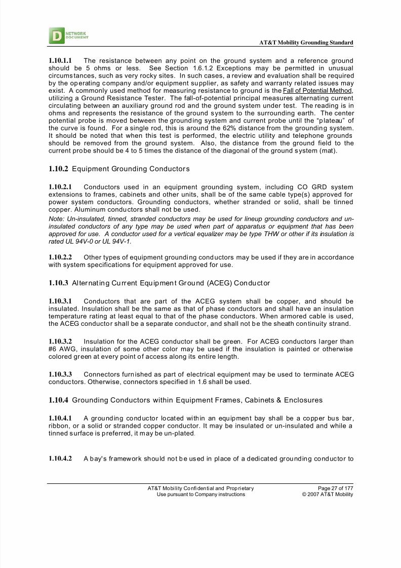
1.10 Ground Resistance Measurement
8/11/2019 At & t ND-00071 Rev 3 Grounding Standard
http://slidepdf.com/reader/full/at-t-nd-00071-rev-3-grounding-standard 27/177

8/11/2019 At & t ND-00071 Rev 3 Grounding Standard
http://slidepdf.com/reader/full/at-t-nd-00071-rev-3-grounding-standard 28/177
AT&T Mobility Grounding Standard
AT&T Mobi li ty Confi dential and Proprietary Page 28 of 177Use pursuant to Company instructions © 2007 AT&T Mobility
extend CO ground reference to any po int with in the bay.
1.10.5 Grounding Conductor Color
1.10.5.1 There are two categories of grounding conductors used in this Standard that must ormay use green insulation; those associated with ac power systems and certain radio systemgrounding conductors.
1.10.5.2 Insulation on grounding conductors used in ac power systems shall be green. Themost common of these are:
(a) Equipment grounding conductors run with feeder and branch circuit conductors(b) Grounding electrode conductors from house service panels and the sources of separatelyderived systems(c) Main and equipment bonding conductors Note: When these conductors are larger than #6 AWG, they may be identified with a suitable means of green marking (tape, paint, etc.).
1.10.5.3 With two exceptions, the insulation of CO GRD conductors should be gray. The firstexception is when an equipment vendor uses a color code on conductors considered within theirequipment system (their "black box"). The other exception is for conductors that are part of theinterior ring ground system at a radio site or a radio room in some other structure, which shouldbe green.
1.10.6 AC System Grounding
1.10.6.1 The AC service distribution system used in a MSC is usually a single or three-phase120/208 or 277/480 volt grounded systems. The grounding of these systems includes two sub-systems: the ac service grounding system and the ac equipment grounding system, covered in2.4.
1.10.7 Grounding Electrode Conductor (GEC)
1.10.7.1 A grounding electrode conductor (GEC) bonds the neut ral of an ac power system to anacceptable earth electrode system. The preferred point of connection of the GEC to an earthelectrode system is via the OPGP.
1.10.7.2 A conductor equal in size to the GEC is requi red between the separate earth electrodesystem and the OPGP.
1.10.7.3 The neutral conductor of an ac system shall not be connected to a grounded object onthe load side of the system's main disconnect device.
1.10.7.4 The GEC shall be sized per Article 250 of the NEC except that conductors smaller than#2 AWG shall not be used for services and conductors smaller than #6 AWG shall not be used forthe source of a separately derived ac power system in any Company structure. See Table 1-2.
1.10.7.5 The GEC may be a bare or insulated, stranded or sol id copper conductor. In an MSCfacility, this conductor should be a green insulated, stranded conductor,.
1.10.7.6 The GEC should be run in the open, or in non-metallic raceway. When required to be in

8/11/2019 At & t ND-00071 Rev 3 Grounding Standard
http://slidepdf.com/reader/full/at-t-nd-00071-rev-3-grounding-standard 29/177
AT&T Mobility Grounding Standard
AT&T Mobi li ty Confi dential and Proprietary Page 29 of 177Use pursuant to Company instructions © 2007 AT&T Mobility
metallic raceway, the raceway must be bonded to the conductor at both ends. If a conductor isused for th is bond, it shall be no smaller than the GEC.
Note: The GEC and associated bonds are often installed by an electrical contractor as directed byCompany specifications.
Size of Largest Service Entrance Conductor or Equivalent Areafor Parallel Conductors
Size of Grounding ElectrodeConductor
Copper Aluminum orCopper-Clad Aluminum
Copper
Up to 1/0 AWG Up to 3/0 AWG 6 AWG
Over 1/0 thru 3/0 AWG Over 3/0 AWG thru 250 kcmi l 4 AWG
Over 3/0 AWG thru 350 kcmi l Over 250 thru 500 kcmil 2 AWG
Over 350 thru 600 kcmil Over 500 thru 900 kcmil 1/0 AWG
Over 600 thru 1100 kcmil Over 900 thru 1750 kcmil 2/0 AWG
Over 1100 kcmil Over 1750 kcmil 3/0 AWG
1.10.8 Main Bonding Jumper
1.10.8.1 A main bonding jumper shall be used to connect the grounded conductor of thesystem (the neutral) to the equipment grounding conductor and service equipment enclosure.
1.10.8.2 The main bonding jumper shall not be smaller than the sizes given in Table 1-2 above,except that sizes smaller than #2 AWG shall not be used for main house service panels inCompany structures. Where the service entrance phase conductors are larger than 1100 kcmilcopper or 1750 kcmil aluminum, the bonding jumper shall have an area not less than 12 1/2percent of the area of the largest phase conductor.
1.10.9 Grounding of Separately Derived AC Systems
Note: A separately derived ac power system is a power source that has no direct electricalconnection, including a solidly connected grounded circuit conductor, to supply conductorsoriginating in another system. Typical sources are isolation transformers, some inverters andsome engine-alternators.
1.10.9.1 A GEC is requi red between the neutral of the source of a separately der ived ac powersystem and an earth ground reference. If available, connect to all grounding electrodes requiredin the NEC, Article 250.52.
1.11 Connectors & Conduit Bonding Devices
1.11.1 Thermal Welding
1.11.1.1 The primary method of thermal welding described in this section is exothermicwelding. Any equivalent method of molecular welding similarly utilizing brass or copper to formthe bond may also be used.
1.11.1.2 Two brand names: Cadweld and Thermoweld are often used in place of the generic
Table 1-2Grounding Electrode Conductor Sizing

8/11/2019 At & t ND-00071 Rev 3 Grounding Standard
http://slidepdf.com/reader/full/at-t-nd-00071-rev-3-grounding-standard 30/177
AT&T Mobility Grounding Standard
AT&T Mobi li ty Confi dential and Proprietary Page 30 of 177Use pursuant to Company instructions © 2007 AT&T Mobility
term exothermic weld. The generic term is used throughout this Standard.
1.11.1.3 Exothermic welds should be used for all buried connections and for connections to
building steel. Where practical, exothermic welds should also be used for above groundterminations on the exterior of the building where the metal is of sufficient thickness to preventburning through the metal.
1.11.1.4 Within build ings, exothermic welding may be used at connection of the CO GRD riserto CO GRD bus bars and bonds to building steel. Other applications may also be practical, suchas connection to the peripheral ground ring in microwave stations and elsewhere.
Note: In occupied areas within a building, the use of exothermic welds should be restricted tothose methods that use “smokeless” or “low smoke emitting” processes, such as the EXOLON ® process from Erico Products, Inc.
1.11.1.5 Exothermic welding shall not be used for connections to thin wall pipe or tubing (.035inch wall or less).
1.11.2 Clamp Type Pipe Connectors and Conduit Bonding Devices
1.11.2.1 For terminations on pipes, grounding clamps should be used when it is not practical touse exothermic welds or threaded type grounding hubs or bushings. When used, clamps, hubs,bushings or other bonding devices shall be listed for their intended use by a nationallyrecognized testing laboratory (NRTL). For clamps, the heavy duty type using bronze saddles arepreferred.
1.11.3 Crimp Type Bolted Tongue Connectors
1.11.3.1 Crimp (compression) type two hole bolted tongue connectors shall be used toterminate stranded grounding conductors. The connectors shall be tin plated copper, long barrel,and shall be listed for their intended use by an NRTL. Note: Tin plated aluminum connectorsinstalled prior to the date of this Standard or connectors that are part of an approved product areacceptable.
1.11.3.2 Crimp type connectors used on solid conductors must be listed by an NRTL for use onsolid conductors, and must be crimped with the dies specified by the manufacturer of theconnector. Use a hydraulic crimping tool.
1.11.3.3 Two-hole bolted tongue connectors shall be used. Wires shall be inserted the entire
length of the lug. An inspection window shall be provided to verify conductor is inserted theentire length. Provide an antioxide compound on the conductor before crimping . Install atransparent heat shrink insulating tubing along the entire length of the crimp.
1.11.4 Pressure Type (Mechanical) Connectors
1.11.4.1 Some grounding conductor termination points preclude the use of exothermic weldsor crimp type connectors. This may be due to physical constraints or because the mechanicalconnector or terminal is a component of a listed or Company-approved product, such as the

8/11/2019 At & t ND-00071 Rev 3 Grounding Standard
http://slidepdf.com/reader/full/at-t-nd-00071-rev-3-grounding-standard 31/177

8/11/2019 At & t ND-00071 Rev 3 Grounding Standard
http://slidepdf.com/reader/full/at-t-nd-00071-rev-3-grounding-standard 32/177
AT&T Mobility Grounding Standard
AT&T Mobi li ty Confi dential and Proprietary Page 32 of 177Use pursuant to Company instructions © 2007 AT&T Mobility
interval of approx imately 18 inches.
1.13.1.3 When a cable bracket or other support detail is placed under a horizontally-rungrounding conductor, the conductor shall be secured to each bracket or support detail usingnylon cable ties or 9-ply waxed polyester twine.
1.13.1.4 Grounding conductors up to and including #1/0 AWG may be secured to the sides ofcable rack stringers, auxiliary framing bars, threaded rods and other ironwork details with nyloncable ties or 9-ply waxed polyester tw ine. See Figure 1-4.

8/11/2019 At & t ND-00071 Rev 3 Grounding Standard
http://slidepdf.com/reader/full/at-t-nd-00071-rev-3-grounding-standard 33/177

8/11/2019 At & t ND-00071 Rev 3 Grounding Standard
http://slidepdf.com/reader/full/at-t-nd-00071-rev-3-grounding-standard 34/177
AT&T Mobility Grounding Standard
AT&T Mobi li ty Confi dential and Proprietary Page 34 of 177Use pursuant to Company instructions © 2007 AT&T Mobility
1.13.2 Connecting and Identifying Conductors
1.13.2.1 Un-plated metallic surfaces shall be prepared to a bare, bright fin ish before joining. Athin layer of corrosion preventive compound such as NO-OX-ID "A" shall be applied to the un-plated surface. Note: If a connector is to be secured directly to a painted surface, the paint shall
be removed down to bare metal and a thin layer of a corrosion preventive compound such as NO-OX-ID "A" shall be applied to the bare metal surface.
1.13.2.2 Bolts, nuts, screws, threaded pressure devices, raceway fittings and every groundsystem connecting or securing device shall be free from corrosion, properly assembled, correctlytightened and accessible for inspection.
1.13.2.3 At OPGP, CO GRD and MGB bus bars, the end of every CO GRD system conductorwhose far end termination is not readily apparent shall be equipped with a destination tagidentifying the termination point of the opposite end of the conductor. These tags are also allowedto be p laced at other points in the CO GRD system.
1.13.2.4 Certain CO GRD system conductors shall be equipped with a brass tag with thephrase: DO NOT DISCONNECT stenciled on it or stamped into it. The letters shall be 3/16"minimum. The following conductors shall always be equipped with this tag: (a) conductors fromearth electrodes (b) grounding conductors at a water pipe or gas pipe
1.13.3 Appl ication of Lock-washers For Grounding Connections
1.13.3.1 This section applies primarily to the use of lock-washers with the securing hardwarefor connectors used to terminate the framework grounding conductor to equipment frameworks,cabinets and other enclosures.
1.13.3.2 These requirements apply when lock-washer information has not been furnished by
another part of this document, a standard drawing, a manufacturer’s drawing or a detailedspecification.
1.13.3.3 When used next to a screw or the head of a screw, in order of preference, a lock-washer may be an external tooth type (ETLW), an internal tooth type (ITLW) or a split ring (helicalspr ing) type. See Figure 1-5
1.13.3.4 For a screw only arrangement (tapped hole), a lock-washer shall be placed betweenthe screw head and the sur face to which it mates. See Figure 1-5.
1.13.3.5 For all types of lock-washers, the material shall be SAE J429 Grade 2 or higher, andthey shall have a zinc electroplate finish.
1.14 Surge Suppressor (TVSS)
1.14.1.1 Building electrical equipment and associated electronic equipment is vulnerable todamage by voltage spikes. These surges could be the result of lightning s trikes, but can also becaused by electric utility system disturbances. Telecommunications and computer systemsequipment housed in the build ing are even more vulnerable to these surges.

8/11/2019 At & t ND-00071 Rev 3 Grounding Standard
http://slidepdf.com/reader/full/at-t-nd-00071-rev-3-grounding-standard 35/177
AT&T Mobility Grounding Standard
AT&T Mobi li ty Confi dential and Proprietary Page 35 of 177Use pursuant to Company instructions © 2007 AT&T Mobility
1.14.1.2 AC Surge Protection Devices (SPD) shall be provided for the electr ic service of allsites housing equipment that is likely to be damaged by a surge in commercial power voltage.Metal-oxide varisters (MOV's) are commonly used for electrical service entrance surge pro tectiondue to their ability to withstand large current surges. Staged MOV protection can be utilized witha suppressor at the main service disconnect and one at the circuit breaker panel-board with
appreciable distance (over 20 feet) between the two. The condui t connecting the TVSS to thepower supply shall be PVC and the leads shall be free of bends and as short as possible. TheTVSS should be installed per manufacturer’s recommendations, consistent with the conceptsmentioned in this Standard for leads to be as short and direct as possible.
1.14.1.3 Silicon avalanche diode (SAD) arresters offer excellent clamping levels, but becomeexpensive when designed to handle large currents associated with service entrance surges. IfSAD arresters are used for main electrical service entrance use (primary suppression), back-upMOV's should be used for secondary suppression. This application may be appropriate forlocations that have experienced repeated equipment failures related to large current surges, orare critical to system integrity (hub sites). When this type of Transient Voltage Surge Suppression(TVSS) is utilized, the following general performance specifications shall apply, as a minimum:
• A TVSS will be employed on the main electrical entrance. The TVSS will be properly sized forthis application. The placement of additional TVSS units on downstream sub-panels is notrequired.
• The unit must respond to transient conditions in 5 nanoseconds or less as a system, not as a
Figure 1-5 Application of

8/11/2019 At & t ND-00071 Rev 3 Grounding Standard
http://slidepdf.com/reader/full/at-t-nd-00071-rev-3-grounding-standard 36/177
AT&T Mobility Grounding Standard
AT&T Mobi li ty Confi dential and Proprietary Page 36 of 177Use pursuant to Company instructions © 2007 AT&T Mobility
component.
• The TVSS shall incorporate an indication panel which denotes whether the primary and/or
secondary protection component(s) is/are functioning.
• The TVSS shall have remote alarming capability.
• All system functions of the TVSS must be individually fused and not short circuit the ac power line
at any time.
• The TVSS unit shall be field replaceable.
• The TVSS must be UL listed.
• The TVSS must comply with ANSI Standard C62.45 testing.
1.14.1.4 T-1 surge protection devices should be installed at the telco entry point beforeconnecting to any other device. The T-1 grounding conductor and surge protection deviceground terminal shall connect to the telco ground bar which is bonded to a low impedance
external ground source. The surge protection devices shall be listed for telephone/data use andutilize, as a minimum, SAD technology.

8/11/2019 At & t ND-00071 Rev 3 Grounding Standard
http://slidepdf.com/reader/full/at-t-nd-00071-rev-3-grounding-standard 37/177
AT&T Mobility Grounding Standard
AT&T Mobi li ty Confi dential and Proprietary Page 37 of 177Use pursuant to Company instructions © 2007 AT&T Mobility
2. MSC/MSC Grounding Requirements
2.1 Scope
2.1.1.1 This section provides requirements for the MSC Ground (CO GRD) system and thegrounding of ac service and distribution systems.
2.2 Earth Electrodes
2.2.1 Driven Ground Electrodes
2.2.1.1 A driven ground rod system may consist of f rom two to any number of rods. The AT&TMobilityStandard is one that forms a ring around the structure. This design helps equalize
potential in the area of the structure.
2.2.1.2 The main (interconnecting) conductor of a driven ground system shall be solid copper,sized at #2 AWG minimum. Tinned wire is required under ground. The conductor shall be placedat a depth of at least 18 inches below grade or 6 inches below the frost line and approximately 24inches from the exterior wall.
2.2.1.3 The ring formed by the main conductor shall be connected to the OPGP/MasterGround Bar with at least two conductors. The preferred design uses conductors connected tooppos ite sides of the ring. This design is feasible for new structures only, because the conductorfrom the far side of the ring must be routed under or within the concrete foundation of thestructure.
2.2.2 Public and Private Water Systems
2.2.2.1 In accordance with Article 250 of the NEC, a metallic underground water pipingsystem, either private or public, shall always be used as a grounding electrode where such asystem is available.
2.2.2.2 To qualify as an earth electrode, the water pipe must be an electrically continuouspiping system. The NEC requires that the buried portion of the system shall be not less than 10feet. For Company applications, it is preferred that the buried pip ing is electrically con tinuous forat least 40 feet.
2.2.2.3 When a water meter is l ocated in the st ructure, the water pipe on the street side of themeter is used as the point of connection if allowed by the water utility. If a connection on thestreet side is not possible, and if allowed by the water utility, the pipe on the bu ilding s ide of themeter may be used as the point of connection when a bonding jumper is provided around themeter.
2.2.2.4 If allowed, the bonding jumper around a water meter shall be the same size as thegrounding electrode conductor.

8/11/2019 At & t ND-00071 Rev 3 Grounding Standard
http://slidepdf.com/reader/full/at-t-nd-00071-rev-3-grounding-standard 38/177
AT&T Mobility Grounding Standard
AT&T Mobi li ty Confi dential and Proprietary Page 38 of 177Use pursuant to Company instructions © 2007 AT&T Mobility
2.2.2.5 When an internal metallic water pipe system exists, the water pipe must be bonded tothe office princ ipal ground point (OPGP) bus bar whether or not the water pipe is used as an earthelectrode.
Figure 2-1
Typical MSC Grounding Detail
2.2.2.6 Per the NEC, a supplemental earth electrode is always required in addition to themetallic water pipe system. When a main water pipe is non-metallic, the supplemental earthelectrode may serve as the grounding electrode system.
2.2.3 Water Well Metallic Casing
2.2.3.1 Where public water systems do not exist and a water supply is required within astructure, a drilled well with metallic casing and electrically continuous piping may be provided.The well may be located on the property outside the structure or beneath the structure. While theNEC states that 10 feet of combined pipe and casing exposed to earth is an adequate electrode, awell casing that penetrates to a depth of at least 40 feet is preferred.
2.2.3.2 In special circumstances, it may be economical to install well casing and pipe as a

8/11/2019 At & t ND-00071 Rev 3 Grounding Standard
http://slidepdf.com/reader/full/at-t-nd-00071-rev-3-grounding-standard 39/177
AT&T Mobility Grounding Standard
AT&T Mobi li ty Confi dential and Proprietary Page 39 of 177Use pursuant to Company instructions © 2007 AT&T Mobility
supplementary ground system rather than a driven ground system. This may apply in areas wheregravel or other earth conditions make effective grounding by means of driven rods impractical orwhere a driven rod system at an existing s tructure is economically unfeasible.
The well need not be functional as a water supply to serve as an earth electrode. Generally, adriven supplementary ground field will be more economical than a well supplied for groundingpurposes only, unless special cost considerations are a factor.
2.2.4 Other Electrodes
2.2.4.1 Other earth electrodes can be alternatives for Company structures.
2.2.4.2 A concrete encased electrode (sometimes referred to as an Ufer ground) isrecommended for new sites. However, if the site's geological conditions preclude the use of adriven ground rod system, a concrete encased electrode may be used. It shall:
(a) Be a continuous minimum #2 AWG solid tinned copper conductor(b) Be placed in the footing around for a minimum of 20 ft.(c) Have one end of the #2 AWG connected to the OPGP using exothermic welds.(d) Be placed in a footing that is in direct contact with the earth with no moisture barriersinterrupting the contact
2.2.4.3 If a concrete encased electrode system is available at any site, such as a leasedbuilding, it must be bonded to the structure's earth electrode system.
2.2.4.4 A second option for an earth electrode system when ground rods cannot be driven is acounterpoise system. The horizontal counterpoise system consists of minimum #2 AWG barecopper conductors, with rods if they can be driven radiating from the ring ground system from thefour corners of the structure.
2.2.4.5 The counterpoise conductors shall be run in a straight line, to the edge of ownedproperty or for a maximum length of 125 feet, whichever is the lesser. They shall not be less than25 feet long.
2.2.4.6 Gas service pipe, tanks, pipes (other than water pipes or well pipes) or plateelectrodes are prohib ited.
2.2.5 Inter-bonding of Earth Electrodes
2.2.5.1 Each ground rod of a driven ground system and every other intentional driven groundrod or buried object in the vicinity of a structure that may act as an unintentional electrode shallbe bonded together to lim it potential difference between them.
2.2.5.2 An optimum separation of intentional earth electrodes is from 10 to 15 feet or from 1.5to 2 times their length, whichever is greater. Proximity of any type of electrode at less than 6 feetto any other is not desirable and it is recommended that such occurrences be avoided wherepractical.
2.2.5.3 When a driven ground system is installed around a structure equipped with lightning

8/11/2019 At & t ND-00071 Rev 3 Grounding Standard
http://slidepdf.com/reader/full/at-t-nd-00071-rev-3-grounding-standard 40/177
AT&T Mobility Grounding Standard
AT&T Mobi li ty Confi dential and Proprietary Page 40 of 177Use pursuant to Company instructions © 2007 AT&T Mobility
protection, the lightning protection systems down conductors shall be connected to the drivenground system rather than to separate lightning protection system ground rods.
2.2.6 MSC Ground System
2.2.6.1 The MSC Ground system provides:
(a) Grounding of communication systems equipment(b) Earth potential reference for ac and dc power systems and communications circuits(c) Lightning discharge path to earth(d) Current paths for equalization of dc voltages
2.2.6.2 The CO GRD system includes conductors that extend from:
(a) The OPGP to CO GRD bus bars located on each floor of a building(b) CO GRD bus bars on each floor to the battery return systems of dc power plants, otherprincipal dc distribution components and if present, other vertical risers(c) CO GRD bus bars to equipment frames, cabinets and other metallic objects on equipment
floors, and are referred to as framework or equipment ground, and by other names derived fromthe served equipment or the function of the conductor
2.2.6.3 A CO GRD system shall be provided in every new MSC bui ld ing and equipment area inother structures.
2.2.7 Office Principal Ground Point (OPGP) or Master Ground Bar
2.2.7.1 The office principal ground point serves as a central connecting point for groundingconductors f rom with in the structure and from earth electrodes. For a single story MSC/MSC thisis referred to as the Master Ground Bar (MGB). The most common conductors terminated at theOPGP are:
(a) The ac service Grounding Electrode Conductor(b) A bond to the Cable Entrance Facility(c) A bond to the interior gas and/or water pipe system in the structure(d) Bonds to structural steel(e) Bonds to supplementary ground fields(f) A CO GRD system vertical riser(g) A bond to the earth electrode system in an adjacent structure(h) Bonds to equipment requiring an earth ground reference
2.2.7.2 New structures or those undergoing significant reconstruction should employ adesign that places OPGP, the main ac service equipment and the cable entrance facility as closetogether as practicable. In new structures and existing structures where an OPGP is being added
or relocated, a location shou ld be chosen that will remain accessible and near the main electricalservice entrance.
2.2.7.3 The former Standard of locating the OPGP directly on the main water pipe is no longerrecommended. This applies to both MSC’s and commercial build ings. Note: While the main waterpipe is not recommended as a location for the OPGP, it is still a requirement to provide a bondfrom the metallic water pipe to the OPGP.
2.2.7.4 The size of the OPGP bus bar shall accommodate the initial conductors plus a 50

8/11/2019 At & t ND-00071 Rev 3 Grounding Standard
http://slidepdf.com/reader/full/at-t-nd-00071-rev-3-grounding-standard 41/177
AT&T Mobility Grounding Standard
AT&T Mobi li ty Confi dential and Proprietary Page 41 of 177Use pursuant to Company instructions © 2007 AT&T Mobility
percent growth factor, and in no case shall it be smaller than the minimum size for a CO GRD busbar: 1/4" x 4" x 16" .
2.2.7.5 Where practicable, the OPGP bus bar shall be mounted horizontally on min imum 3/4”studs welded to structural steel. If such an arrangement would place the OPGP in a less
centralized or less accessible location, the bus bar’s location can be altered provided a bond isprovided between the OPGP and structural steel.
2.2.7.6 If structural steel is not available for bonding, insulators providing at least 2" ofseparation shall be placed between the OPGP and its mounting surface. These insulators mayalso be used if the mounting studs are not used as a means to bond the OPGP to buildingstructural steel. In any case, the 2" separation is required to provide working access between thebus bar and the mounting sur face.
2.2.7.7 At the OPGP, an exothermic weld is the preferred method for terminat ing the two #2 AWG sol id conductors from the buried ground r ing system.
2.2.7.8 If a building addition is abutted to an existing structure and is provided with a new andseparate ac service, a separate OPGP may be established. A bond shall be provided between thetwo principal ground points using a conductor sized as follows:
(a) For buildings with less than 4 floors (including a basement), the conductor shall be the samesize as the largest grounding electrode conductor provided for either the existing building or thebuilding addition.(b) For buildings with 4 or more floors, the conductor shall be a 750 kcmil
2.2.7.9 When a common communication installation is housed in two closely adjacentstructures (i.e., separated by an alley) having individual earth electrodes, the OPGP’s shall bebonded together. The bond shall be the same as described for abutted buildings above.
2.2.7.10 Metal pipes and other buried objects having entry to the structure may act asunintentional earth electrodes. These electrodes shall be made common with the intentionalelectrode(s) using a minimum #2 AWG bond between their entry point and the OPGP. A single #2
AWG conductor may be branched to bond two or more of these objects.
2.2.8 Inter-bonding
2.2.8.1 Inter-bonding should be included in the building ground system design for any newstructure without regard to its intended use. It should also be added to MSC buildings when anysignificant renovation is performed on the building ground system or a main house service panelor during a major building construction project.
2.2.8.2 At minimum, inter -bonding must always include three general elements wi th in astructure. These are the utility power service entrance, the telco cable entrance and the earthelectrode entrance. The points of connection for the inter-bonding conductors are shown inFigure 2-2 and are described as fo llows:
(a) A point at or near the communication cable's entrance into the structure - the cable entrancefacility (CEF)(b) A point on the neutral bus bar in the HSP for the conductor to the OPGP (groundingelectrode conductor)(c) A point on the HSP's equipment ground bus bar close to the connection of the main bonding

8/11/2019 At & t ND-00071 Rev 3 Grounding Standard
http://slidepdf.com/reader/full/at-t-nd-00071-rev-3-grounding-standard 42/177
AT&T Mobility Grounding Standard
AT&T Mobi li ty Confi dential and Proprietary Page 42 of 177Use pursuant to Company instructions © 2007 AT&T Mobility
jumper from the neutral bus bar for the conductor to the CEF(d) A point of access to the structure's primary earth electrode, most often the OPGP Inter-bonding exists when these points are connected together.
2.2.8.3 In structures with more than one OPGP, HSP and/or CEF, bonds shall be placed
between any one of these points and at least two other points in the inter-bonding system.
2.2.8.4 In MSC’s, a copper bus bar must be provided in the CEF area. It must be:
(1) A minimum size of 2" wide, 12" long and 1/4" thick(2) Equipped with a permanent label: CABLE ENTRANCE GROUND BAR(3) Mounted on insulators that provide at least 2" of clearance from its mounting surface(4) Located at a convenient point to serve the cable shield bonding conductors, and if required,protector unit grounding conductors.
2.2.8.5 On the OPGP, the preferred connection po int for the conduc tors from the HSP and theCEF is nearest the point of connection of the conductors from the driven ground system, buildingstructural steel or the main water pipe.
2.2.8.6 In the HSP, it is essential that the conductor from the CEF is connected to the acequipment ground (ACEG) bus bar as close as possible to the point of connection of the mainbonding jumper from the neutral bus bar. Terminating this cable on a neutral bus bar isprohibited.
2.2.9 Cable Sheathing
2.2.9.1 Telephone cable and fiber cable metallic sheaths entering the building shall be grounded. The field side of the cable sheath shall be bonded to the telco ground bar which is located outsidethe IGZ. The telco ground bar shall have direct continui ty to the buried ground ring. Additionally,a direct run shall be provided from the telco ground bar to the "P" section of the MGB. Fiber optic
cables entering the facility should have the metallic sheath or trace conductor grounded at thefiber ground bar, which i s located outside the IGZ. The fiber ground bar shall be copper, ¼”D x4”H x 12”L and shall have a direct connection to the buried ground r ing. Additionally, a direct runshall be provided from the fiber ground bar to the “P” section of the MGB.
2.2.10 Design Parameters - Vertical Riser System
2.2.10.1 In a single story build ing, a vertical riser is the conductor between the OPGP and a COGRD bus bar. In multi-floor buildings it also bonds the CO GRD bus bars together. It provides alow impedance path to the earth electrode system via its connection to the OPGP. Equipment thatrequires a connection to the earth electrode system for proper operation and/or protection canuse the connection to a floor's CO GRD bus bar because it is considered an appearance of the
grounding electrode. Also, the vertical riser serves as a current path for battery return currentinterchange between circuits on different floors and as a low impedance fault current path.
2.2.10.2 The location of a vertical riser shall be such that the maximum conductor lengthbetween a CO GRD bus bar and the furthest grounded equipment unit does not exceed 200 feet.This means that the equipment served may not be located outside the perimeter of a square (200'x 200') superimposed on a circle with a 100' radius, centered at the location of the CO GRD busbar. This is shown in 2-3 below.

8/11/2019 At & t ND-00071 Rev 3 Grounding Standard
http://slidepdf.com/reader/full/at-t-nd-00071-rev-3-grounding-standard 43/177
AT&T Mobility Grounding Standard
AT&T Mobi li ty Confi dential and Proprietary Page 43 of 177Use pursuant to Company instructions © 2007 AT&T Mobility
Figure 2-2
Typical Inter-bonding Arrangement
2.2.10.3 The vertical riser shall be located so that the hor izontal portion of the run to the OPGPis as shor t as practical.
2.2.10.4 A vert ical r iser shal l consist of a cont inuous 750 kcmi l copper conductor or i t may be asteel building co lumn. When a 750 kcmil conductor is used, the vertical run shall be as straight aspractical, preferably with only minor bends to avoid obstruc tions such as floor beams.
2.2.10.5 Splices in a 750 kcmil vertical riser shall be made using either an exothermic weld oran in-line crimp type connector. A 750 kcmil vertical riser conductor may also be extended using acrimp type parallel connector tapped onto an existing vertical riser conductor.
2.2.10.6 Certain types of building columns may be used as a vertical riser. Other types cannotbe used for this purpose but require bonding to floor CO GRD bus bars. When column steelconsists of structural steel sections, and all section butt ends of the column are bridged with aweld, a welded steel plate or an exothermically welded or brazed 750 kcmil copper bond, thecolumn may be used as a CO GRD system vertical riser. Bonds between CO GRD bus bars andcolumn steel shall be made using a 750 kcmil copper conductor, two 3/4" studs welded to thesteel column or an equivalent means (see Figure 2-4).

8/11/2019 At & t ND-00071 Rev 3 Grounding Standard
http://slidepdf.com/reader/full/at-t-nd-00071-rev-3-grounding-standard 44/177
AT&T Mobility Grounding Standard
AT&T Mobi li ty Confi dential and Proprietary Page 44 of 177Use pursuant to Company instructions © 2007 AT&T Mobility
2.2.10.7 When structural steel of a column is not welded or bonded, it may not be used as avertical riser. However, an equalizing bond shall be provided between the column steel in closestproximity to each bus bar. The bond shall be made using one of the methods used when thecolumn steel is used as a CO GRD vertical riser, except that when a conductor is used, it need beno larger than #3/0 AWG.
2.2.10.8 When columns are reinforced concrete and reinforcing bars are not welded or wirewrapped, it is assumed that continuity to earth does not exist. For this reason, column reinforcingbars not known to be electrically continuous to earth shall not be bonded to the CO GRD busbars.
Figure 2-3Maximum Floor Area Served by a Vertical Riser

8/11/2019 At & t ND-00071 Rev 3 Grounding Standard
http://slidepdf.com/reader/full/at-t-nd-00071-rev-3-grounding-standard 45/177
AT&T Mobility Grounding Standard
AT&T Mobi li ty Confi dential and Proprietary Page 45 of 177Use pursuant to Company instructions © 2007 AT&T Mobility
Figure 2-4
Bonding CO GRD Bus Bar to Building Steel
2.2.10.9 When a vertical steel column i s used as the CO GRD conductor, that column must beconnected to the OPGP with a 750 kcmil copper conductor. This conductor should be as short aspracticable, and shall be exothermically welded or brazed directly to the column steel, orconnected to a ground bar.
2.2.10.10 A vertical riser may serve a horizontal CO GRD system which does not exceed 200conductor feet from a CO GRD bus to the furthest equipment frame, as explained above. Whenthis distance will be exceeded, a second vertical riser with associated CO GRD bus bars andhorizontal equalizers is required.
2.2.10.11 When multiple vertical risers are required, they shall be located within 200 feet of eachother so that horizontal equalizers can serve a contiguous fl oor area.
2.2.10.12 Multiple vertical risers shall be bonded together at the lowest floor and at every thirdfloor w ith a 750 kcmil conductor. For example, bonds would be made in the basement, at the third,sixth, nin th, etc., floors.
2.2.10.13 The second vertical riser shall terminate at the OPGP except when the horizontalportion of the first vertical riser extends from the OPGP in the direction of the second verticalriser. In this case, the second vertical riser may terminate at a CO GRD bus bar served by the firstequalizer or tapped to the equalizer conductor on the floor containing the OPGP if the resultant

8/11/2019 At & t ND-00071 Rev 3 Grounding Standard
http://slidepdf.com/reader/full/at-t-nd-00071-rev-3-grounding-standard 46/177
AT&T Mobility Grounding Standard
AT&T Mobi li ty Confi dential and Proprietary Page 46 of 177Use pursuant to Company instructions © 2007 AT&T Mobility
run length from the OPGP to the vertical portion of the second equalizer is not greater than 120percent of a direct run between the two points.
2.2.10.14 An exothermic weld or cr imp type parallel connector shall be used when Vert icalRisers are joined to share a common 750 kcmil path to the OPGP.
2.2.10.15 When multiple vertical risers are installed in a building, they shall be designated as COGRD #1, CO GRD #2, etc.
Multistory buildings that are separated by an alleyway or permanent building wall require one or moreseparate Vertical Risers in each building. The risers shall be designated CO GRD #1, CO GRD # 2, etc.,when ac or dc supplies of either building provide power to equipment in the other building. The equalizersshall terminate on the OPGP of their respective building, and a bond shall be provided between the twoOPGP’s.
2.2.10.16 Acceptable methods for bonding a 750 kcmi l ver tical riser to the CO GRD bus bar areshown in Figure 2-5 and described below:
(1) A 750 kcmil conductor is exothermically welded to the edge(s) of the bus bar. On the bottom
floor of a building, the conductor from the OPGP and the one to the next floor's CO GRD busbar may both be welded to the top (or sides) of the bus bar.(2) A short length of 750 kcmil is exothermically welded to the bus bar. The other end is tapped,using a crimp type H-tap, to the vertical riser. This method allows the weld to the bus bar to bemade at some other location (e.g., outside).(3) Same as arrangement (2), but both connections are made with exothermic welds.(4) A "flag" type connector is crimped to the vertical riser and bolted to the bus bar.(5) Same as arrangement (2), but both connections are crimp type.
2.2.10.17 In the past, the recommended Standard was to extend a separate 750 kcmil horizontalequalizer from a floor's CO GRD bus bar into each quarter section of the floor area. While this isstill acceptable, the size of the building and the amount and type of equipment to be served by the
CO GRD system should be evaluated to determine the need for this arrangement. Often, a single750 kcmil or smaller conductor routed along a main aisle is an alternative that will provide anacceptable arrangement and w ill satisfy any foreseeable needs.
2.2.10.18 A minimum #2 AWG conductor shal l be used between the CO GRD bus bar and an areacontaining a group of bays or miscellaneous units, or an area with more than one lineup ofequipment. Separate #6 AWG conductors may then be branched from this conductor to serve anequipment lineup or individual equipment un its. The #2 AWG conductors may originate at the COGRD bus bar, or from another horizontal equalizer of equal or larger s ize.
2.2.10.19 When a BDFB is located in an area not served by a 750 kcmil horizontal equalizer, theBDFB's #1/0 AWG DCEG conductor may serve in p lace of the #2 AWG described above. If a BDFBhas a 750 kcmil conductor between its return bus and a CO GRD bus bar, this is considered to be
a horizontal equalizer, and may be used as such.
2.2.10.20 Al l new extensions of , or branches from a horizontal equalizer conductor shall bemade with crimp type parallel connectors.

8/11/2019 At & t ND-00071 Rev 3 Grounding Standard
http://slidepdf.com/reader/full/at-t-nd-00071-rev-3-grounding-standard 47/177
AT&T Mobility Grounding Standard
AT&T Mobi li ty Confi dential and Proprietary Page 47 of 177Use pursuant to Company instructions © 2007 AT&T Mobility
Figure 2-5
Methods of Connecting 750 kcmil Vertical Riser to CO GRD Bus Bar
Design Parameters - Horizontal Equalizer System
2.2.11 CO Ground Bus Bars
2.2.11.1 At least one CO GRD bus bar is required on every floor of a structure wi th a CO GRDsystem. The bus bar shall be located on the column that serves as the Vertical Riser or on acolumn or wall when a vertical riser is a separate conductor.
2.2.11.2 The preferred location for the bus bars on equipment floors is the approximate centerof the equipment area. Where a CO GRD bus bar cannot be centrally located, it should be locatedas near as practicable to the protector frames or other distributing frames equipped with

8/11/2019 At & t ND-00071 Rev 3 Grounding Standard
http://slidepdf.com/reader/full/at-t-nd-00071-rev-3-grounding-standard 48/177
AT&T Mobility Grounding Standard
AT&T Mobi li ty Confi dential and Proprietary Page 48 of 177Use pursuant to Company instructions © 2007 AT&T Mobility
protectors.
2.2.11.3 The CO GRD bus bar in a building's basement need not be in vertical alignment withother floor CO GRD bus bars. It should be located at a point along the CO GRD vertical riser run inthe basement, and in a position that affords the shortest practical run length o f the bond between
the vertical riser and the predominant power plant, if one exists.
2.2.11.4 The bus bar should be located approximately 12"-18" below the lowest layer ofironwork. This location will allow access to the bus bar, help maintain an acceptable conductorbending radius, and furnish an adequate span of support for conductors.
2.2.11.5 The bond between a vertical riser and a CO GRD bus bar shall be as short aspracticable, and in no case shall be more than 20 feet.
2.2.11.6 In single floor buildings, more than one CO GRD bus bar may be provided. Theadditional bus bars may be connected directly to the OPGP or to the vertical riser serving anotherbus bar. If the direct route to the OPGP results in a run length 25% less than the run via another
bus bar, the direct route should be used.
2.2.12 Designation of OPGP & CO Ground Bus Bars
2.2.12.1 Al l CO GRD bus bars on all floors and all OPGP bus bars shall be designated. Thedesignations may be stamped on the bus bar or engraved in or stamped on a separatedesignation plate. The plate must be securely fastened to either the bus bar or to the surface ofthe wall or column adjacent to the bus bar.
2.2.12.2 The preferred size for the characters used in the designation is 3/4" and in no caseshall the characters be smaller than 1/2".
2.2.12.3 The terms used in designations for floor CO GRD bus bars are to be either “CO GRD” ,“ C.O. GRD”, “ C.O. Ground” or “ MSC Ground” . For OPGP bus bars, the terms used in thedesignations are to be either “OPGP” , "O.P.G.P." or "Office Principal Ground Point” or “ MasterGround Bar.” Terms such as "Telco Ground" or "Telephone Ground" are not to be used.
2.2.13 Office Drawings
2.2.13.1 Record drawings shall be used to record the follow ing information:
(a) the location of CO GRD, MGB, OPGP and other bus bars used primarily for terminatinggrounding conductors(b) A cross reference table containing cable sizes, connector identifiers and any other piece
parts associated with terminating CO GRD system conductors(c) The approximate route of all CO GRD conductors (other than ACEG conductors) up to theirpoint of connection to equipment frames, cabinets or other enclosures(d) Where appropriate, figures showing the connection sequence of conductors(e) Any figures or notes required by engineering or installation to describe groundingarrangements unique to the area covered by a drawing
2.2.14 Routing and Support of Equalizer Conductors

8/11/2019 At & t ND-00071 Rev 3 Grounding Standard
http://slidepdf.com/reader/full/at-t-nd-00071-rev-3-grounding-standard 49/177
AT&T Mobility Grounding Standard
AT&T Mobi li ty Confi dential and Proprietary Page 49 of 177Use pursuant to Company instructions © 2007 AT&T Mobility
2.2.14.1 Al l ver tical and horizontal equalizer conductors shou ld be routed so that U shapedconfigurations are avoided. Where such turns are unavoidable, they shall be made with thegreatest possible radius.
2.2.14.2 Vertical and Horizontal Equalizers shall be run exposed so as to afford visualinspection of the entire system and to provide access for adding connectors .
2.2.14.3 Vertical and horizontal equalizer conductors shall be run through concrete or otherpermanent masonry floors and walls in core-drilled holes or non-ferrous conduit. If a cable hole isadjacent to the vertical or horizontal equalizer, it may be used in place of non-ferrous metalconduit as long as a discernable separation is maintained between the vertical riser and otherconductors routed through the cable hole.
2.2.14.4 Vertical risers shall be secured to columns and walls using supports locatedapproximately 2 feet from the floor, the ceiling, each side of any intervening bus bar, and at aninterval of 2 feet (or less) between these points.
2.2.14.5 The vertical conductor may be supported by cable brackets or similar details fastenedto sections of strut channel or other material anchored to a wall or column. An auxiliary supportshall be provided on every other floor consisting of either wedge plugs in the top of sleeves orcable support grips suspended from J-bolts secured by anchors in the ceiling.
2.2.15 Building Engineering
2.2.15.1 The exact location of vertical risers shall be determined by Building Engineering basedon the requirements described in preceding paragraphs.
2.2.15.2 For buildings with s tructural steel, the preferred method is to use the welded structural
steel as the vertical riser.
2.2.15.3 When it is intended that structural steel columns be used as vertical risers,instructions for bonding of the structural steel sections, as described in preceding paragraphs,shall be included in building specifications.
2.2.15.4 When bonding of floor CO GRD bus bars to building steel is required the BuildingEngineer shall arrange for the addition of the two 3/4" studs or the 750 kcmil conductor tobuilding steel prior to pouring of concrete.
2.2.15.5 The installation of sleeves in floors and requirements associated with buildingconstruction should be included in construction specifications. When sleeves are placed at
columns, care should be exercised to offset them from the column to miss horizontal beams whilenot i nterfering with clear equipment aisle space.
2.2.15.6 Where more than one vertical riser system is required in a building and bonding isrequired between them, suitably located sleeves through intervening walls that will result inshortest practical run lengths shall be provided.
2.3 Switching Equipment Grounding Features

8/11/2019 At & t ND-00071 Rev 3 Grounding Standard
http://slidepdf.com/reader/full/at-t-nd-00071-rev-3-grounding-standard 50/177
AT&T Mobility Grounding Standard
AT&T Mobi li ty Confi dential and Proprietary Page 50 of 177Use pursuant to Company instructions © 2007 AT&T Mobility
2.3.1.1 In addition to meeting the requirements for grounding and lightning protection outlined herein, the isolation of switching equipment from voltage disturbances incorporates the followinggrounding features:
An isolated ground zone
A single ground reference for equipment
Dedicated DC power plants
2.3.1.2 In any building that houses communication equipment, a ground plane existsthroughout the structure. Continuity is extended by deliberate bonding, such as provided byconduit and AC equipment ground conductors of the distribution system, and unit bonds off ofthe interior ground ring. Other paths occur through struc tural steel, water piping, air ducts,superstructures, cable racks, and other building material. These various conductors are eitherdeliberately or incidentally inter-bonded to form an integrated ground plane. During fault occurrencesin the AC or DC power system, a large amount of current can be imposed on the ground plane.Lightning strokes on the building, or on AC conductors or telephone cables serving the building,can cause tremendous surges of current through the integrated ground plane. This current, if
allowed to flow through the ground plane of an electronic system, could produce stresses thatwould cause malfunctions, damage or destruction of components. Therefore, it is recommended tocontinuously monitor the integrity of the grounding and bonding system. This is accomplished byregular routine inspections by local staff, or equipment that continuously monitors the electricalenvironment for dynamic current changes, providing real time alarms and reports that showanomalies or compromises in the ground system.
2.3.2 Isolated Bonding Network
2.3.2.1 Al l components referenced to ground at a sing le point reside in an isolated bondingnetwork. When two or more equipment systems are connected to the same GWB, they are notseparate isolated bonding networks; they are separate entities within the same isolated bondingnetwork is referenced to the common bonding network at the same point.
Note: Isolated bonding network is now used in place of Isolated Ground Plane, and the term
common bonding network is now used in place of Integrated Ground Plane.
2.3.3 Ground Window
2.3.3.1 The ground window is an imaginary sphere with a maximum diameter of 6 feet. It maybe helpful to picture it as a set of boundaries that defines the physical limits of the main groundbus, which is the actual interface between an isolated bonding network and a building's commonbonding network. The diameter of the ground window ensures that the GWB provides the desiredelectrical environment while furnishing enough room to terminate a fairly large number of
conductors. The size of the ground window also helps limit the length of bonding conductorsbetween the GWB and objects passing through the ground w indow, thus provid ing a relatively lowimpedance shunt. Note: The term ground window has been used as though i t is in terchangeablewith GWB, even to the point where the GWB has been stenciled "Ground Window". These twoterms define different objects and should be used appropriately. Because it is the physical pointof connection (a bond can't be made to an imaginary object), GWB is the most appropriate term touse when discussing engineering, material, and installation requirements.
2.3.3.2 Some of the key elements of an isolated bonding network and its association with the

8/11/2019 At & t ND-00071 Rev 3 Grounding Standard
http://slidepdf.com/reader/full/at-t-nd-00071-rev-3-grounding-standard 51/177

8/11/2019 At & t ND-00071 Rev 3 Grounding Standard
http://slidepdf.com/reader/full/at-t-nd-00071-rev-3-grounding-standard 52/177

8/11/2019 At & t ND-00071 Rev 3 Grounding Standard
http://slidepdf.com/reader/full/at-t-nd-00071-rev-3-grounding-standard 53/177
AT&T Mobility Grounding Standard
AT&T Mobi li ty Confi dential and Proprietary Page 53 of 177Use pursuant to Company instructions © 2007 AT&T Mobility
2.5.1.3 The default size for the conductor between the GWB and a CO GRD or OPGP bus barshall be 750 kcmil. A smaller conductor may be used, depending on the capacity of the powerplant serving the isolated bonding network equipment. Table 2-1 shall be used to select theminimum s ize of the conductor using a Plant Capacity value that is the maximum possib le for thetype of power plant used.
Figure 2-7Relationship between Common and Isolated Bonding Networks
(Ground Window is l ocated above power plant)

8/11/2019 At & t ND-00071 Rev 3 Grounding Standard
http://slidepdf.com/reader/full/at-t-nd-00071-rev-3-grounding-standard 54/177
AT&T Mobility Grounding Standard
AT&T Mobi li ty Confi dential and Proprietary Page 54 of 177Use pursuant to Company instructions © 2007 AT&T Mobility
Maximum PlantCapacity (Amperes)
Minimum Size of SystemGrounding Conductor
Up to 100 6 AWG
101 – 500 2 AWG
501 – 1199 4/0 AWG
1200 or more 750 kcmil
Table 2-1
Minimum Size of Conductor between GWB and CO GRD (For MSC’s)
2.5.1.4 Some equipment/power plant arrangements may use conductor sizes other than thoseshown in Table 2-1, for example some remote switching equipment sys tems. For all installations,the conductor shall be the minimum size specified by the manufacturer of the isolated bondingnetwork equipment.
2.6 Master Ground Bar
2.6.1 Master Ground Bar (MGB)
2.6.1.1 The master ground bar (MGB) is the primary ground reference point for an MSC (Also
referred to as the OPGP). It is defined as a ground bar used to collectively terminate, as a singlepoint of ground reference, surge producers, surge absorbers, and equipment grounds. The MGBis a copper bar, typically 48 inches long, 1/4 inches thick, and 4 inches wide. It is insulated fromits support, and physically located near the electrical service entrance and the telephone cableentrance.
2.6.1.2 The MGB serves as the interface point between the isolated ground zone's IGB and thebuilding integrated ground plane. Direct bonds of min imal practical length are required from theMGB to points on different objects compris ing a part of the building integrated ground plane. Useof such bonds ensures that voltage difference between members of the two planes will beequalized to the greatest possible extent. Such equalization tends to reduce the incident of spark-over between the two planes, and possibilit y of shock hazard to personnel interposed between theplanes.
2.6.1.3 The MGB is a common point for terminating surge producers "P", surge absorbers"A", non-isolated ground zones "N", and isolated ground zones "I". The MGB shall be divided intobonding sections, where all connections within a particular section will be of the same type. Also, thesections shall be placed left to right in this order; "P" (leftmost), "A", "N", and "I" (rightmost). Thepurpose of this is to place the surge absorbers between the source and the electronic equipment

8/11/2019 At & t ND-00071 Rev 3 Grounding Standard
http://slidepdf.com/reader/full/at-t-nd-00071-rev-3-grounding-standard 55/177
AT&T Mobility Grounding Standard
AT&T Mobi li ty Confi dential and Proprietary Page 55 of 177Use pursuant to Company instructions © 2007 AT&T Mobility
as an additional protection during fast rise time surges, such as lightning s trikes.
2.6.1.4 There are three primary surge absorbers "A" connected to the MGB. They are:
• The earth ground field
• Building steel
• The metallic water system
2.6.1.5 The MGB may be located above or below a power distribution frame in an equipmentarea. If permitted by the equipment manufacturer, it may be the same bus bar used to terminatebattery return conductors from the power plant.
In some isolated bonding network systems, the power distribution frames are cabled from below and havebattery and battery return bus bars mounted above the cable rack near the ceiling on the floor below theequipment. For the purpose of determining maximum floor separation between an MGB and parts of anisolated bonding network, the MGB is considered to be on the floor on which it is located.
2.6.2 GWB at Power Plant with Insulated Return Bus
2.6.2.1 When a power plant's battery return bus bar is insulated from the power plant'sframework or supporting ironwork, a portion (up to 6 feet) of the bus bar may be used as theGWB. The plant's battery return bus bar may be a straight section of bus bar or it may be astacked arrangement. Examples are shown in Figure 2-9
2.6.2.2 When the battery return bus bar of the power plant consists of one or more straightsections of bus bar longer than six feet, the GWB may be established at any point along the busbar. See details 1A and 1B in Figure 2-9. Battery return conductors serving common bondingnetwork loads shall be terminated on the battery return bus bar with in the boundaries of the GWB.Battery return conductors for isolated bonding network loads shall be terminated on theremaining portion(s) of the battery return bus bar.
2.6.2.3 To determine which part of the battery return bus bar is used as the GWB when astacked bus bar arrangement is used, consideration must be given to:
(a) The ampacity of all bus bars and their interconnecting details(b) The location on the bus bar for the plant's grounding conductor (from a CO GRD or OPGPbus bar)(c) The termination points for all other conductors - this is called sequencing and is described insection 2.6.4.

8/11/2019 At & t ND-00071 Rev 3 Grounding Standard
http://slidepdf.com/reader/full/at-t-nd-00071-rev-3-grounding-standard 56/177
AT&T Mobility Grounding Standard
AT&T Mobi li ty Confi dential and Proprietary Page 56 of 177Use pursuant to Company instructions © 2007 AT&T Mobility
Figure 2-8
MSC Master Ground Bar – MGB Detail

8/11/2019 At & t ND-00071 Rev 3 Grounding Standard
http://slidepdf.com/reader/full/at-t-nd-00071-rev-3-grounding-standard 57/177
AT&T Mobility Grounding Standard
AT&T Mobi li ty Confi dential and Proprietary Page 57 of 177Use pursuant to Company instructions © 2007 AT&T Mobility
2.6.3 GWB at Power Plant with Un-insulated Return Bus
2.6.3.1 While not a preferred arrangement, power plants with no insulation between thebattery return bus and the framework can be adapted to serve isolated bonding network loads, butonly if the ground window is established at the power plant.
Note: These are typically 302 and similar type plants, and they almost always have a battery return bus
longer than six feet. Since it is impractical to insulate the battery return bus bar or re-terminate all of the
existing battery return conductors within a 6-foot area, an auxiliary bus bar called an Isolated Return Bus
is required.
2.6.3.2 The isolated return bus bar shou ld be added to the existing battery return bus bar at alocation that keeps the physical separation between the battery and battery return conductors to a
minimum. The isolated return bus shall be either:(a) a bus bar detail with one end equipped with an insulator between the supporting ironworkand the bus bar, and the other end connected to the existing battery return bus bar, or(b) A separate bus bar with both ends mounted on insulators and calculated conductors (at leastone 750 kcmil) between the isolated return bus and the existing battery return bus bar.
2.6.3.3 The isolated return bus is not considered part of the GWB, and bonds normally madeto the GWB, such as those from conduits or other common bonding network objects shall not beconnected to this bus bar.
2.6.3.4 The isolated return bus bar must be bonded to the existing battery return bus bar at apoint as close as practicable to the point of connection of the power plant grounding conductor
from a CO GRD or OPGP bus bar. An equipment vendor's grounding specifications may require additional conductors between the isolatedbonding network equipment and the GWB, such as those for framework or logic ground. Theseconductors may be connected to the GWB or to the isolated return bus bar. When connected to eitherbus bar, they shall be placed so that they are nearest the point of connection between the two bus bars.
2.6.4 Sequencing
2.6.4.1 Sequencing i s a method used to control the placement of connections to a GWB. It is aconcept that provides both electrical and practical benefits. Some conductors are arranged ingroups that are considered to be either more likely to conduct fault current or are more sensitiveto fault current and other transients. Listing the conductors in a specific order is done to satisfythese concerns and for the sake of uniformi ty.
2.6.4.2 There is flexibility in the placement of conductors along a GWB. Using the connectionfrom CO GRD as a reference point, the physical sequence of connections below should bemaintained relative to the connection to CO GRD. Groups are identified by brackets, the numbersin circles are for identification, and some conductors may not be present.
Note: Connections are allowed to be in a different sequence within their group, for example the location ofconductors and could be reversed.

8/11/2019 At & t ND-00071 Rev 3 Grounding Standard
http://slidepdf.com/reader/full/at-t-nd-00071-rev-3-grounding-standard 58/177
AT&T Mobility Grounding Standard
AT&T Mobi li ty Confi dential and Proprietary Page 58 of 177Use pursuant to Company instructions © 2007 AT&T Mobility

8/11/2019 At & t ND-00071 Rev 3 Grounding Standard
http://slidepdf.com/reader/full/at-t-nd-00071-rev-3-grounding-standard 59/177
AT&T Mobility Grounding Standard
AT&T Mobi li ty Confi dential and Proprietary Page 59 of 177Use pursuant to Company instructions © 2007 AT&T Mobility
Figure 2-9Examples of Battery Return Bus BAR/GWB Arrangements

8/11/2019 At & t ND-00071 Rev 3 Grounding Standard
http://slidepdf.com/reader/full/at-t-nd-00071-rev-3-grounding-standard 60/177
AT&T Mobility Grounding Standard
AT&T Mobi li ty Confi dential and Proprietary Page 60 of 177Use pursuant to Company instructions © 2007 AT&T Mobility
2.6.4.3 If a new isolated bonding network entity will be served by a GWB located above orbelow a power distribution bay that is a part of an existing isolated bonding network entity, it isnot necessary to rearrange the existing connections to the GWB to meet sequencingrequirements.
2.6.5 Remote GWB
2.6.5.1 It may be beneficial to locate the GWB at a location that provides more convenientrouting of grounding conductors, conduits and/or battery return conductors. This may be done onthe initial job adding the GWB, or it may be done during equipment growth. When the GWB islocated at a point where it is neither a part of the power plant's battery return bus nor the batteryreturn bus bar above/below an isolated bonding network power distribu tion bay, it is considered aRemote GWB.

8/11/2019 At & t ND-00071 Rev 3 Grounding Standard
http://slidepdf.com/reader/full/at-t-nd-00071-rev-3-grounding-standard 61/177
AT&T Mobility Grounding Standard
AT&T Mobi li ty Confi dential and Proprietary Page 61 of 177Use pursuant to Company instructions © 2007 AT&T Mobility
2.6.6 Relocating an Existing GWB
2.6.6.1 It is not a requirement to move a GWB when the switch it or iginally served is removed.Relocating the GWB should be done only after careful examination of several site-specific
Figure 2-10Sequencing of Conductors along a GWB that is
Part of a Power Plant’s Battery Return Bus

8/11/2019 At & t ND-00071 Rev 3 Grounding Standard
http://slidepdf.com/reader/full/at-t-nd-00071-rev-3-grounding-standard 62/177
AT&T Mobility Grounding Standard
AT&T Mobi li ty Confi dential and Proprietary Page 62 of 177Use pursuant to Company instructions © 2007 AT&T Mobility
conditions, and if possible, should include the potential impact from forecasted growth. Keyfactors affecting a GWB’s relocation include:
(a) Floor location (vertically) of new, remaining and future isolated bonding network equipmentserved by the GWB (b) Location of the power plant serving other equipment connected to the GWB
(c) Location of common bonding network equipment whose battery returns are currently bondedto the GWB (d) Power plant battery return bus bar termination points of battery return conductors from existing common bonding networkequipment
(e) Affect on length of DCEG conductors between existing equipment and new location of GWB
2.6.6.2 When a GWB is relocated, continuity between the GWB and CO GRD must bemaintained at all times. Two connections between the isolated bonding network and the CO GRDsystem are allowed only during the time required to re-establish a single point groundarrangement. This transition period should be as short as possible.
2.7 Bonds to the Ground Window Bar
2.7.1 Conduits, Raceways, and Other Conductive Paths
2.7.1.1 Metallic conduits and raceways containing ac circuits serving isolated bondingnetwork equipment must be routed through the ground window and bonded to the GWB. The
ACEG conductor in the conduit must also be bonded to the GWB.
2.7.1.2 The bond to the GWB shall be made using a minimum #6 AWG conductor no morethan three feet in l ength. Figure 2-10 shows one possible method to bond the conduit and ACEGconductors to the GWB. A mechanical connector may be used to create a collection point toprovide a means to bond ACEG conductors, conduit, raceway and junction box (if used) and the#6 AWG bond to the GWB.
2.7.1.3 Af ter passing through the ground window into the isolated bonding network, condui tmay contact isolated bonding network metalwork, but it must remain insulated from contact withmembers of the common bonding network.
2.7.1.4 Al l metall ic condui ts and raceways containing ac ci rcui t conductors shall beintentionally bonded together to form an electrically continuous enclosure. Insulating bushings,non-conductive unions, or any similar material or methods shall not be used in metallic conduitsor raceways to interrupt their continuit y.
2.7.1.5 Every conductor with continuity to both the common bonding network and the isolatedbonding network, such as the shield of a coaxial cable, shall pass through the ground window and
be bonded to the GWB with a conductor no longer than 3 feet.

8/11/2019 At & t ND-00071 Rev 3 Grounding Standard
http://slidepdf.com/reader/full/at-t-nd-00071-rev-3-grounding-standard 63/177
AT&T Mobility Grounding Standard
AT&T Mobi li ty Confi dential and Proprietary Page 63 of 177Use pursuant to Company instructions © 2007 AT&T Mobility
2.8 Isolation of Communications Equipment
Figure 2-11Bonding of Conduit and ACEG Conductors to GWB

8/11/2019 At & t ND-00071 Rev 3 Grounding Standard
http://slidepdf.com/reader/full/at-t-nd-00071-rev-3-grounding-standard 64/177
AT&T Mobility Grounding Standard
AT&T Mobi li ty Confi dential and Proprietary Page 64 of 177Use pursuant to Company instructions © 2007 AT&T Mobility
2.8.1.1 Isolation of equipment is accomplished by the use of insulators between the metalliccommon points where the integrated ground plane is fastened to the IGZ. Such points shallinclude:
Anchor bolts. Frame anchor bolts may touch grounded structural metal in a floor provided an
insulator separates bolt heads from the frame metal. These insulators should be slightly larger
than the bolt heads to prevent foreign metallic objects from shorting the bolt head and frame
metal together, as the case would be if a small screw were kicked under the bolt head.
The bottom of frames. A sheet of insulating material is placed between the frames and the floor.
Superstructure supports. Brackets extended above the frames support unistrut channels that, in
turn, support fluorescent lighting fixtures, conduits, and power cable racks that are part of the
integrated ground plane. Insulators placed on top of the support brackets isolate the switch
plane.
Conduits and receptacles. If conductive conduits are used, they shall pass through and be
bonded to the GWB, and be insulated for the remainder of the run. Conduits connected to switch
IGZ equipment and supported from unistrut lighting support channels are insulated by means of
fiber sheeting wrapped around the conduit at points of support. Alternately, non-conductive PVC
conduit may be used.
Al l AC receptacles within the IGZ shall be of the isolated (yolk) orange-coded type and
comply with NEC Article 250. This exception provides for an insulated, grounding conductor.
This grounding conductor (green with yellow stripes) shall be bonded to the GWB as the conduit
passes by the bar, so that ground for the receptacles is part of the IGZ. In most cell sites,
inverters are no longer used. Equipment space is confined to a small area so that the electrical
system is referenced to the CRGB, negating the necessity to provide isolated outlets at cell sites.
2.8.2 Lighting System Components
2.8.2.1 Lighting fixtures within the IGZ may be connected to the AC distribution panel in theconventional manner per NEC Article 250, providing there is no electrical contact with any part ofthe equipment located within the IGZ. The minimum requirements for an adequate ground bondof lighting system components are as follows:
• Panel-board - A No.6 AWG bond shall be provided from the interior or exterior of the panel board
enclosure to the interior ground ring.
• Unistrut channel support network - The support channels shall be joined to the integrated ground
plane. A ground path is assumed to exist through any metallic interconnection of channels,
except fluorescent lighting fixture runs. Where such metallic interconnection does not exist,
isolated channels, or groups of channels, shall be bonded with No. 6 AWG wire as required to
from the channel network into an inter-conductive unit.
• The unistrut channel network shall be bonded with No. 6 AWG wire to the GWB.

8/11/2019 At & t ND-00071 Rev 3 Grounding Standard
http://slidepdf.com/reader/full/at-t-nd-00071-rev-3-grounding-standard 65/177

8/11/2019 At & t ND-00071 Rev 3 Grounding Standard
http://slidepdf.com/reader/full/at-t-nd-00071-rev-3-grounding-standard 66/177
AT&T Mobility Grounding Standard
AT&T Mobi li ty Confi dential and Proprietary Page 66 of 177Use pursuant to Company instructions © 2007 AT&T Mobility
2.8.3.2 The original definition of the term "close proximity" was "a separation of less than 3feet when common bonding network members are inter-bonded with a CO GRD system or 6 feetwhen interconnections depend on incidental ground paths." Because not all equipment vendorsagree on a single requirement for this dimension, the 6-foot distance should be used to determinewhether or not an object is in close proximity.
2.8.3.3 Individual objects may be assumed to be grouped if reasonably direct paths ofcontinuity exist between them and other objects that are also in close proximity to the IsolatedBonding Network. Continuity may consist of any metallic path that is bolted or similarly fastenedtogether such as strut channel, ironwork, cable racks, conduit clamps, frame supports, batteryreturn conductors, and CO GRD conductors. For example, when the ironwork above isolatedbonding network equipment is an extension of the ironwork above common bonding networkequipment frames, the ironwork is often adequately bonded via the framework groundconnections to the common bonding network equipment frames. Additional direct bonds areusually not warranted. This is illust rated in Figure 4-8 as follows: the ironwork is connected to thecommon bonding network equipment frames via the top support details, the frames are connectedto the CO GRD bar via the equipment grounding conductors, and the path is completed via theconnection between the CO GRD bar and the GWB.
2.8.3.4 Electrical conduit, lighting fixtures, superstructure metal, common bonding networkequipment frames, ventilation ducts, metal piping, and other conductive objects at a site areassumed to be part of the common bonding network. When electrically continuous, they may beused to provide a bonding path to other objects. Note: Connections between points in the foreignobject bonding system may be made using a "daisy-chain" arrangement. This is illustrated inFigure 2-12 by the connection between the air conditioning duct and the framing channel.
2.8.3.5 When objects are not considered adequately bonded by means such as mechanicalconnections, separate #6 AWG bonding conductors shall be provided to a poin t on each object orgroup o f objects that results in the shortest run length . The most common example of this is whenventilation ducts and ironwork are suspended from separate, individual anchors instead of from acommon s trut channel imbedded in the ceiling.
2.8.3.6 A sing le bond ing conductor may be extended to a common locat ion on floors otherthan the one containing the GWB and spliced and extended to different groups requiring a bond.
2.8.3.7 Al l foreign object bonding conductors are part of the common bonding network andshall be kept insulated from contact with metallic objects that are part of the isolated bondingnetwork.
2.8.3.8 Members of one isolated bonding network may be located on three adjacent floors,and many common bonding network objects may be in close proximity to isolated bondingnetwork members on each floor. It is impractical and unnecessary to run a separate bondingconductor from the GWB to each object. These items may be bonded together and assumed to be
one object, requiring on ly a single #6 AWG conductor between the MGB and a point on the group,under the allowances and restrictions outlined above.
2.8.3.9 When the protector frame is not on the same floor as the GWB, no connection isrequired between the protector frame and the MGB other than that normally provided via the COGRD system.

8/11/2019 At & t ND-00071 Rev 3 Grounding Standard
http://slidepdf.com/reader/full/at-t-nd-00071-rev-3-grounding-standard 67/177
AT&T Mobility Grounding Standard
AT&T Mobi li ty Confi dential and Proprietary Page 67 of 177Use pursuant to Company instructions © 2007 AT&T Mobility
2.9 Isolated Bonding Network Equipment
Figure 2-12Foreign Object Bonds to Nearby Metallic Objects

8/11/2019 At & t ND-00071 Rev 3 Grounding Standard
http://slidepdf.com/reader/full/at-t-nd-00071-rev-3-grounding-standard 68/177
AT&T Mobility Grounding Standard
AT&T Mobi li ty Confi dential and Proprietary Page 68 of 177Use pursuant to Company instructions © 2007 AT&T Mobility
2.9.1 Isolated Ground Bar (IGB)
2.9.1.1 The isolated ground bar (IGB) is the reference point for the isolated ground zone (IGZ).The isolated ground bar (IGB) col lectively terminates equipment with in the IGZ. The IGB is aground reference ONLY, and it is not used to carry normal load current. Connections are per
individual equipment manufacturers' installation practices. The battery ground return (reference)conductors connecting to the GWB extend the switch ground reference to the batteries. The IGBis a copper bar (1/4” x4”x18” typically) mounted on insu lating supports and phys ically locatedinside the IGZ. The IGB is bonded by one 2/0 (minimum) or larger wire directly to the "I" section ofthe GWB. This wire should be engineered for the particular switch. Where practical, the GWB andIGB shall be located close together. It is recognized that this cannot always be achieved;therefore, no restriction is specified for the length of the conductor, as long as its resistance doesnot exceed 0.005 ohms.
2.9.2 Isolated Ground Zone Restrictions
2.9.2.1 Only one isolated ground bar (IGB) may be utilized with a single isolated ground zone (IGZ).
This is necessary to protect switch solid state components and printed wiring boards frompossible damage in case of a lightning strike on the building or other voltage disturbancesoriginating outside the equipment area served by the isolated ground plane.
2.9.2.2 The single point connection in the master ground bar (MGB) integrates the switch IGZwith the integrated plane for the purpose of equalizing voltage between the otherwise isolatedplanes. The single point restricts current generated by a lightning strike on the building fromflowing through equipment frames to earth. Additionally, current spikes generated by equipmentoperation or malfunction in systems that are not connected to the isolated ground plane cannotcourse through that plane since at least two connections are required to complete a circuit.
2.9.2.3 Al l isolated bonding network equipment systems current ly in use contain at least twogrounding sub-systems, generically referred to as framework ground and logic ground. Somedesigns also use battery return conductors to provide ground reference to all or part of anequipment system. While battery return conductors are considered to be grounded conductors,when used to provide a ground reference, they are also acting as grounding conductors and are apart of another grounding sub-system.
2.9.2.4 Every grounding sub-system used in isolated bonding network equipment shall beconnected to a site's common bonding network sys tem at only one point : the GWB
2.9.2.5 Al l components of every ground sub-system shall be designed to safely conduct anyfault current li kely to be present.
2.9.3 Framework Ground Systems
2.9.3.1 In isolated bonding network equipment, the framework ground system consists of allconductors and components between the GWB and the point of attachment to a frame or cabinet.
2.9.3.2 Some framework ground system designs include connections to other grounding sub-

8/11/2019 At & t ND-00071 Rev 3 Grounding Standard
http://slidepdf.com/reader/full/at-t-nd-00071-rev-3-grounding-standard 69/177
AT&T Mobility Grounding Standard
AT&T Mobi li ty Confi dential and Proprietary Page 69 of 177Use pursuant to Company instructions © 2007 AT&T Mobility
systems and to battery return. Some designs have restrictions that allow connection betweenframework ground and other grounding sub-systems only at the GWB. One design requires anintermediate bus bar between the equipment and the GWB that serves as a collection point forindividual conductors from each equipment lineup.
2.9.3.3 DCEG conductors shall be copper and sized per Table 2-2. The rating or setting of thelargest of the first upstream over-current device in all dc power circuits supplying equipmentlocated in a frame or cabinet shall be used for the left-hand column in Table 2-2. Usually, aconductor larger than #6 AWG is required only for secondary power d istribut ion f rames (PD, PDC,PCFD, etc.).
2.9.3.4 If a DCEG conductor is in a form other than bare or insu lated stranded wire, it shall beequal in circular mil area to the conducto r required per Table 2-2.
2.9.3.5 The DCEG conductor may be attached at either the top or bottom of the frame orcabinet. This connection shall be made with a two-hole crimp type connector unless the means ofattachment has been evaluated and approved for use.
Rating or Setting of AutomaticOvercurrent Device in Circui t
AheadOf Equipment, Not Exceeding
(Amperes)
Minimum Size ofCopper Equipment
Grounding Conductor (AWG)
200 6
300 4
500 2
600 1/0
Table 2-2Minimum Size of DCEG Conductors
2.9.4 Logic Ground Systems
2.9.4.1 Logic ground may also be referred to as logic return or signal ground. Since it isconnected to the return side of a dc-dc converter's output, the logic ground conductor isessentially a dc power source's system ground ing conductor.
2.9.4.2 Depending on the design of the equipment system, logic grounds may be connecteddirectly to the GWB, to the GWB via the framework ground system, a logic ground collectionsystem, the battery return system, or a combination of methods.

8/11/2019 At & t ND-00071 Rev 3 Grounding Standard
http://slidepdf.com/reader/full/at-t-nd-00071-rev-3-grounding-standard 70/177
AT&T Mobility Grounding Standard
AT&T Mobi li ty Confi dential and Proprietary Page 70 of 177Use pursuant to Company instructions © 2007 AT&T Mobility
2.9.4.3 Logic ground conductors are usually provided on an individual shelf or frame basis.Unless some other means has been evaluated and approved, logic ground conductors shall beattached using bo lted crimp type connectors .
2.9.5 Battery Return Systems
2.9.5.1 A number of battery return conf igurations are used wi th in the isolated bondingnetwork equipment. For voltage equalization, the first (analog) electronic systems used a gridsystem connected between the battery return bus bars of power distri bution bays. Newer designsmay include an equalization network, although they are usually less extensive than the earlydesigns.
2.9.5.2 When a battery return conductor is also used as a grounding conductor, it must be ofsufficient size to conduct any fault current likely to be present. Unless some other means hasbeen evaluated and approved, battery return conductors shall be attached using bolted crimp typeconnectors.
2.9.6 Equipment Separation and Circuit Location
2.9.6.1 A minimum separat ion of 4 feet should be provided between isolated bonding networkframes and equipment frames in the common bonding network. This separation also applies tocables and cross-connection fields. Cable racks and other metallic structures shall be separatedso that the only point of contact between the isolated bonding network and the common bondingnetwork is at the GWB in the ground window .
2.9.6.2 Common bonding network circuits, regardless of the type of framework on which theyare mounted or whether they have been rated as operationally compatible with isolated bondingnetwork equipment, shall be located outside the isolated bonding network. The only exceptionsshould be circuits that have been specifically designed as an integral part of the isolated bonding
network equipment.
2.9.6.3 The requirement that framework comprising a portion of the isolated bonding networkbe no more than one floor away from the ground window does not restrict location of electroniccircuit ry. Such circuitry may be located on any floor if:
(a) It is electrically isolated from mounting framework but is mounted in framework that isbonded to the common bonding network via the CO GRD system, and(b) The circuit components are insulated or otherwise separated from members of the common bonding network so that voltagedifferential developed between the isolated bonding network and the common bonding network will not allow current spark-over orrepresent a hazard to personnel.
2.9.7 Insulation
2.9.7.1 Insulating material shall be installed between a metallic object that is part of theisolated bonding network and material securing or fastening it to a metallic object that is part ofthe common bonding network.
2.9.7.2 Insulating material shall have a minimum dielectric strength of 400 volts/mil and shallhave sufficient mechanical strength to withstand physical forces likely to be applied duringinstallation.

8/11/2019 At & t ND-00071 Rev 3 Grounding Standard
http://slidepdf.com/reader/full/at-t-nd-00071-rev-3-grounding-standard 71/177
AT&T Mobility Grounding Standard
AT&T Mobi li ty Confi dential and Proprietary Page 71 of 177Use pursuant to Company instructions © 2007 AT&T Mobility
2.9.7.3 Floor and wall anchoring material is often in contact with concrete and may touchstructural metal. An insulator shall be used between anchor bolt heads (or stud nuts) and isolatedbonding network frame or cabinet metalwork.
2.9.7.4 Insulating material shall be placed between the floor and the bottom of all frames,
cabinets or o ther metallic objects that are part of the isolated bonding network. The material shallbe of sufficient size and strength that isolation is maintained when the securing hardware istightened.
Any metal detail extended above isolated bonding network equipment to support an object thatis part of the common bonding network shall use insulation material to maintain separationbetween the two bonding networks.
2.9.7.5 Conduits that are part of an isolated bonding network shall be insulated from contactwith common bonding network objects using two wraps of sheet fiber placed at all support points.When specifically approved by a Company representative, plastic tape may be used if it is:
(a) Insulating type plastic tape intended for electrical use(b) Listed by a nationally recognized testing laboratory (NRTL) such as Underwriters
Laboratories Inc. (UL)(c) A minimum of 8.5 mils thick by 3/4" wide(d) Applied in a minimum of 2 overlapped (half-lapped) layers that result in a minimum total of 4layers of tape at any given point on the conduit(e) Applied in a continuous wrap that extends a minimum of 1/2" beyond each edge of a conduitclamp or any other metallic object in contact with the conduit.
2.10 Power Plants
2.10.1.1 Dedicated 24 and 48 volt power plants are provided to supply DC power to the sys temcircuit s. These plants are dedicated to serve equipment associated with one isolated ground zoneonly. The discharge ground bus bars of these plants are insulated from the plant framework to
eliminate contact of the discharge system with any ground source, except that of the isolatedground plane. Connect frames and metallic objects in the Power Room to a reference ground bar(1/4” x 4” x 18” typically).
2.10.2 Power Plant Location
2.10.2.1 The power plant should be as close as practical to the isolated bonding network,preferably on the same floor. In existing buildings, space restrictions or other factors may causethe power plant to be located several floors from the equipment it serves, which is not thepreferred location, but is acceptable.
2.10.3 Power Plants Serving Common and Isolated Bonding Network Equipment
2.10.3.1 Common bonding network equipment may be served by a power plant that servesisolated bonding network equipment provided:
(a) the secondary power distribution bays (BDFBs, etc.) for the common bonding network equipment are supplied by separatebattery and return feeders from the plant's primary distribution bays, and
(b) The battery return of the feeder circuit is routed through the ground window and bonded tothe GWB before terminating in the secondary distribution bay.

8/11/2019 At & t ND-00071 Rev 3 Grounding Standard
http://slidepdf.com/reader/full/at-t-nd-00071-rev-3-grounding-standard 72/177
AT&T Mobility Grounding Standard
AT&T Mobi li ty Confi dential and Proprietary Page 72 of 177Use pursuant to Company instructions © 2007 AT&T Mobility
Note: When the GWB is a part of the power plant's battery return bus bar, the battery return conductorsserving common bonding network distribution bays shall be connected within the area of the bus bardesignated as the GWB.
2.10.3.2 The battery conductor need not be paired with the battery return conductor for theportion of the run to and from the GWB if a significant amount of additional cable for the batteryconductor is required to maintain pairing. The return conductor must be closely coupled (to itself)along the route to and from the point where it leaves the route of the battery conductor and theconnection to the GWB. Where significant conductor length is not a factor, the battery and batteryreturn conductors shall remain paired. See Figure 2-13. Note: When the battery return conductoris longer than the battery conductor, the size of the battery return conductor shall be adjusted, ifnecessary, to meet any voltage drop requirements.
2.10.3.3 The battery return conductors of a circuit serving common bonding networkequipment may be connected directly to the GWB or, to save space on the GWB, they may bebonded to the GWB with a conductor not exceeding 3 feet in l ength. This is shown in Figure 2-13.
Note 1: One bonding conductor may be serially connected, using crimp type parallel connectors, to morethan one battery return conductor, provided the bonding conductor is no longer than 3 feet.
Note 2: The bonding conductor shall be the same size as the battery return conductor for sizes up to #1/0 AWG. Larger conductors may be bonded using a #1/0 AWG.
2.10.3.4 Certain power equipment may be treated as iso lated bonding network equipment eventhough it is physically located in the common bonding network. To qualify for this exception, theequipment must:
(a) Not have continuity between its battery return terminals and the frame or cabinet or othercommon bonding network objects, and(b) Be a single load (not a secondary distribution bay).
Note: Common examples of this exception are inverters and dc-dc converters with isolated outputs.
2.10.4 Different Isolated Bonding Networks Served by the Same Power Plant
2.10.4.1 A power plant may serve more than one isolated bonding network ent ity. Everyisolated bonding network entity served by the same power plant must be bonded to the sameGWB. No part of these entities may be located more than one floor from the GWB.
2.10.4.2 Secondary power distribution frames that are a part of an isolated bonding networkentity are usually prohibited (by the manufacturer) from serving equipment in other isolatedbonding network systems. For this reason, power distribution equipment may serve equipment inanother isolated bonding network entity only with the permission of both equipmentmanufacturers.

8/11/2019 At & t ND-00071 Rev 3 Grounding Standard
http://slidepdf.com/reader/full/at-t-nd-00071-rev-3-grounding-standard 73/177
AT&T Mobility Grounding Standard
AT&T Mobi li ty Confi dential and Proprietary Page 73 of 177Use pursuant to Company instructions © 2007 AT&T Mobility
2.11 AC Equipment Grounding
2.11.1 Feeder and Branch Circuit Equipment Grounding System
2.11.1.1 A separate ACEG conductor shall be provided in all condui ts , raceways and otherdistribution systems containing ac circuit conductors.
2.11.1.2 A separate ACEG conductor shall be provided in all addit ions, rearrangements orextensions of service, feeder and branch circuit raceways. This includes distribution systemsserving both communication equipment and building service equipment.
2.11.1.3 An addit ional insulated ACEG conductor is requi red for all ci rcui ts feeding isolatedground type outlets. This conductor must remain insulated from contact with any other ground
Figure 2-13Methods o f Bonding Battery Return Conductors to the GWB

8/11/2019 At & t ND-00071 Rev 3 Grounding Standard
http://slidepdf.com/reader/full/at-t-nd-00071-rev-3-grounding-standard 74/177
AT&T Mobility Grounding Standard
AT&T Mobi li ty Confi dential and Proprietary Page 74 of 177Use pursuant to Company instructions © 2007 AT&T Mobility
reference between the circuit load(s) and its source (HSP, isolation transformer, dc-ac inverter,etc.).
2.11.1.4 A separate bonding jumper is required between a receptacle and i ts enclosure with thefollowing exceptions:
(a) The receptacle is an isolated ground type(b) The receptacle is cover-mounted and the enclosure and cover combination are listed as providing satisfactory ground continuitybetween the enclosure and the receptacle
2.11.1.5 Except for ACEG conductors serving isolated ground type receptacles, all ACEGconductors shall be bonded to metal enclosures to provide continuity independent of thatprovided by the raceway. A single bond may be used between multip le ACEG conductors and anenclosure.
2.11.1.6 An ACEG conductor shall be connected to an enclosure by one of the followingmeans:
(a) A ground bus bar
(b) A terminal strip(c) A grounding bushing(d) A grounding clip(e) A screw fastener
Note 1: Grounding clips are normally used only at junction boxes and receptacle enclosures.Note 2: A screw fastener (machine screw, nut, bolt or stud) must be used for no other purpose than toterminate ACEG conductors.
2.11.1.7 ACEG conductors shall never be connected to an ac neutral at any point downstreamfrom the point where the source of the system receives its ground reference.
2.11.1.8 The ACEG conductor shall be included in calculations of allowable percentage ofcondui t fill defined in Chapter 9 of the National Electric Code. The ACEG conductor is notincluded in the ampacity de-rating calculation for 4 or more conductors per article 310 of the NEC.
2.11.1.9 At minimum, all ACEG conductors and bonds between them and metall ic enclosuresshall be sized per Table 2-3 below, which is from Article 250 of the NEC.
Note: When phase conductors are increased in size to compensate for voltage drop, the size ofassociated ACEG conductor(s) shall be increased proportionately.
2.11.1.10 Where conductors are run in parallel in multiple raceways, ACEG conductors shall berun in parallel. Each parallel ACEG conductor shall be sized on the basis of the ampere rating ofthe over-current device protecting the circu it conductors in the raceway in accordance with Table
2-3.
2.11.1.11 Insulated ACEG conductors shall be colored green. Conductors larger than #6 AWGmay be identified by marking the exposed insulation with green tape or paint at each end and atevery poin t where the conductor is accessible.
2.11.1.12 When multiple ac circuits share a common raceway, only one ACEG conductor isrequired for the raceway. Its size shall be based on the largest over-current device serving circuit s

8/11/2019 At & t ND-00071 Rev 3 Grounding Standard
http://slidepdf.com/reader/full/at-t-nd-00071-rev-3-grounding-standard 75/177

8/11/2019 At & t ND-00071 Rev 3 Grounding Standard
http://slidepdf.com/reader/full/at-t-nd-00071-rev-3-grounding-standard 76/177
AT&T Mobility Grounding Standard
AT&T Mobi li ty Confi dential and Proprietary Page 76 of 177Use pursuant to Company instructions © 2007 AT&T Mobility
Note: If the transfer switch does switch the neutral, then the engine-alternator or inverter is considered thesource of a separately derived system and must be equipped with a GEC and a main bonding jumper.
Rating or Setting of AutomaticOvercurrent Device in Circuit
Ahead
Of Equipment, Not Exceeding(Amperes)
Minimum Size ofCopper Equipment
Grounding
Conductor
15 14 AWG
20 12 AWG
30 10 AWG
40 10 AWG
60 10 AWG
100 8 AWG
200 6 AWG
300 4 AWG
400 3 AWG
500 2 AWG
600 1 AWG
800 1/0 AWG
1000 2/0 AWG
1200 3/0 AWG
1600 4/0 AWG
2000 250 kcmil
2500 350 kcmil
3000 400 kcmil
4000 500 kcmil
5000 700 kcmil
6000 800 kcmil
Table 2-3
Minimum Size of Equipment Grounding ConductorFor Grounding Raceway and Equipment
2.11.4.2 An ACEG conductor is always requi red in the condui t(s) or raceway(s) contain ing

8/11/2019 At & t ND-00071 Rev 3 Grounding Standard
http://slidepdf.com/reader/full/at-t-nd-00071-rev-3-grounding-standard 77/177
AT&T Mobility Grounding Standard
AT&T Mobi li ty Confi dential and Proprietary Page 77 of 177Use pursuant to Company instructions © 2007 AT&T Mobility
phase leads from the alternator, and shall be furnished in accordance with the requirementsabove.
2.11.4.3 The ACEG conductor(s) shall terminate within the engine-alternator cabinet providedfor the phase leads. Termination may be made on a bus bar or ground stud bonded to the cabinet
or directly to the cabinet interior. The cabinet must be electrically connected to the engine-alternator frame by mounting bolts or by a bonding strap or equivalent means to providecontinuity between the entire set and the ACEG conductors.
2.11.4.4 The neutral of the alternator shall not be bonded to the ACEG conductor or engine-alternator frame when it is located in the same building as the main ac service panel. The neutralshall be bonded to the ACEG conductor only when the set is located in a separate buildingequipped with it s own earth electrode, or if the neutral is sw itched.
2.11.5 Grounding of AC Tap Boxes
2.11.5.1 Every ac tap box shall be equipped with an ACEG bus bar. This bus bar shall be
bonded to the metalwork of the tap box by its mounting hardware or by a separate bondingconductor.
2.11.5.2 A separate ACEG conductor shall be furnished in the raceway serving the tap box.The ACEG conductor shall be installed per NEC requirements.
2.11.6 Cord Connected AC Operated Equipment
2.11.6.1 Parallel polarized U ground slot receptacles are standard for frame base applianceoutlet and other miscellaneous ac branch circuit applications serving cord connected equipment.Such equipment, whether portable or permanently mounted, shall be equipped with a threeconductor cord and a three conductor grounding attachment plug. Two conductors of the cord
shall serve as circuit members. The third conductor shall serve as a grounding member,connected at the plug to the U blade, and to the equipment structural metal, so that groundcontinuity is established from the receptacle to the equipment structure.
2.11.6.2 When branch circuit conductors are not run in electrically cont inuous metallic racewayan ACEG conductor must be provided from the panel-board to the receptacle. The ACEGconductor shall be bonded to the metal outlet box or other enclosure mounting the receptacle aswell as the EG (green) terminal screw of the receptacle.
2.11.6.3 If ground continuity is not provided to the U ground slot via the receptacle mountingmembers, a bonding jumper is required.
2.11.6.4 Certain equipment still in use may be equipped with 2-pole ungrounded plugs and 2-conductor cords. Unless protected by an approved system of double insulation, such units arepotentially hazardous. Such cord and plugs shall be replaced with 3-conductor cords and 2-pole,3-conductor grounded plugs.
2.11.6.5 Where units suitably arranged for grounding are used in offices with 2-poleungrounded receptacles, the plug shall be equipped with a ground conductor type adaptor toensure that grounding facility is available.

8/11/2019 At & t ND-00071 Rev 3 Grounding Standard
http://slidepdf.com/reader/full/at-t-nd-00071-rev-3-grounding-standard 78/177

8/11/2019 At & t ND-00071 Rev 3 Grounding Standard
http://slidepdf.com/reader/full/at-t-nd-00071-rev-3-grounding-standard 79/177
AT&T Mobility Grounding Standard
AT&T Mobi li ty Confi dential and Proprietary Page 79 of 177Use pursuant to Company instructions © 2007 AT&T Mobility
3. Power Plants and Equipment
3.1 Scope
3.1.1.1 This section covers requirements and information about connections between a MSC ground system and:
−power equipment−transport equipment−miscellaneous equipment frames and units−cable entrance facilities−protector and distributing frames−power systems serving the above and other types of equipment
3.2 General
3.2.1.1 This section provides requirements for equipment that is normally installed in acommon bonding network environment. It includes requirements for power plant equipment andpower distribution systems that serve both common bonding network and isolated bondingnetwork equipment.
Where requirements are specified in circuit drawings or specifications of equipment approvedfor use, they shall have precedence over the general requirements of this Section.
3.2.2 An Overview of Power and Grounding Sys tems
Network equipment and the power and grounding systems that serve them are often a mixture
of designs from different eras. Modern equipment may be served by older power and groundingsystems and vice versa. It was once standard practice to connect battery return conductors(also called ground or discharge ground) to bus bars that were in electrical contact withequipment framework. This provided a means to ground the equipment frames by extending theCO GRD system only to critical points in the battery return network. These points were primarilyhorizontal equalizer connections to the return bus bars of BDFBs, equalizing centers and similarpoints in distribution systems. The conductors between these points and equipment framesfunction as both a battery return (grounded) and a framework ground (grounding) conductor.This arrangement also causes dc current (battery return current) flow throughout the hugeparallel network formed by the many metallic paths that are part of bonding and groundingnetworks. Changes in equipment designs have included changes that separate frameworkGround from battery return within the equipment. While this separation of battery return and
framework ground has been a design requirement for some time, equipment (especially powerdistribution equipment) designed prior to this approach is still in use. Today, there is much lessdc current flow on grounding systems in MSC’s. In the future, there may be much less or theremay be much more current flow. This will depend on the design of the equipment as well as thepower distribution and grounding systems. Another common Standard was to place generalpurpose power plants of different voltages reasonably close together. One plant was chosen asthe predominant plant. This was most often the 48-volt plant, since it was generally the one withthe greatest ampere capacity. Some BDFBs served by different plants have fuse panelsdedicated to different voltages, but the BDFB is equipped with a single, common battery return

8/11/2019 At & t ND-00071 Rev 3 Grounding Standard
http://slidepdf.com/reader/full/at-t-nd-00071-rev-3-grounding-standard 80/177

8/11/2019 At & t ND-00071 Rev 3 Grounding Standard
http://slidepdf.com/reader/full/at-t-nd-00071-rev-3-grounding-standard 81/177
AT&T Mobility Grounding Standard
AT&T Mobi li ty Confi dential and Proprietary Page 81 of 177Use pursuant to Company instructions © 2007 AT&T Mobility
equalizer. It may also be connected to the CO GRD system by a connection to a Ground WindowBar (GWB) in the ground window.
Maximum PlantCapacity (Amperes) Minimum Size of SystemGrounding Conductor
Up to 100 6 AWG
101 - 500 2 AWG
501 – 1199 4/0 AWG
1200 or more 750 KCMIL
Table 3-1Battery Plant System Grounding Conductor Sizing For MSC’s
3.2.4.5 The minimum size of the system grounding conductor for dc-dc converters shall bethat shown in Table 3-2, based on the output fault current rating of the converter. The faultcurrent rating shall be the rating of the output over-current protective device or the current limitinception value if no protective device is furnished.
3.2.4.6 For converter plants consisting of two or more converters with outputs connected inparallel, the size of the system grounding conductor shall be based on the combined fault currentavailable from a fully equipped converter plant as specified by the manufacturer. Note: When theoutput of multiple converters embedded in equipment share a common distribution path viabackplane layers, conductors or bus bars, the system grounding conductor shall be sized on thecombined maximum available fault current.
3.2.4.7 Some equipment designs use dc-dc converters whose output is referenced to groundvia the converter's input battery return conductor. When this arrangement is used, the converter'sinput battery return conductor shall be no smaller than that required per Table 3-2.
3.2.5 Power System Equipment Grounding
3.2.5.1 Al l frames, cabinets and other components of a power plant must be equipped wi th aminimum #6 AWG bond to the CO GRD system. This includes frames in a power board lineup,rectifier bays, metal battery stands, etc. A typical power area grounding arrangement is shown inFigure 3-1.
3.2.5.2 DCEG conductors for power plant frames, cabinets and other equipment shall bebranched from a main power plant DCEG conductor. The main conductor shall be #2 AWGminimum, and shall be connected, in order of preference, to the nearest:
(a) Power plant system grounding conductor(b) GWB, when it is part of the plant's battery return bus bar(c) CO GRD horizontal equalizer(d) CO GRD or OPGP bus bar

8/11/2019 At & t ND-00071 Rev 3 Grounding Standard
http://slidepdf.com/reader/full/at-t-nd-00071-rev-3-grounding-standard 82/177
AT&T Mobility Grounding Standard
AT&T Mobi li ty Confi dential and Proprietary Page 82 of 177Use pursuant to Company instructions © 2007 AT&T Mobility
Overcurrent Device Rating
Or Current Limit inceptionNot Exceeding (Amperes)
Minimum Size of System
Grounding Conductor(AWG
15 14
20 12
30 10
40 10
60 10
100 8
200 6
300 4
500 2
600 1/0
Table 3-2
System Grounding Conductor Sizing for DC-DC Converters
3.2.5.3 For any equipment frame, cabinet or other enclosure containing rectifiers, theminimum size for a DCEG conductor shall be #6 AWG. Table 3-3 shall be used to determine thesize of the framework ground conductor based on the size of the output rating of the largestrectifier in the framework.
3.2.5.4 The DCEG conductor for any dc-to-ac inverter shall be a minimum #6 AWG. Table 3-4shall be used to determine the minimum size for the DCEG conductor based on the rating orsetting of the dc input circuit's over-current protective device. This requirement applies to allstand-alone inverters and to all bay-mounted inverters. This DCEG conductor is required inaddition to the ACEG conductor for the ac input and/or output circuits . If the inverter is the sourceof a separately derived system, this conductor is also required in addition to the GroundingElectrode Conductor.

8/11/2019 At & t ND-00071 Rev 3 Grounding Standard
http://slidepdf.com/reader/full/at-t-nd-00071-rev-3-grounding-standard 83/177
AT&T Mobility Grounding Standard
AT&T Mobi li ty Confi dential and Proprietary Page 83 of 177Use pursuant to Company instructions © 2007 AT&T Mobility
Rectif ier OutputRating (Amperes)
DCEGConductor Size
Up to 100 6 AWG
200 4 AWG400 2 AWG
Table 3-3Recti fier DCEG Conductor Sizing
Rating/Setting of DCInput Protective
Device
(Amperes)
DCEGConductor Size
(AWG)
Up to 100 6
200 4
400 2
Table 3-4Inverter DCEG Conductor Sizing
3.2.6 Engine Alternator Equipment
3.2.6.1 For engine rooms located within a structure, the grounding system shall be the sameused for equipment in a power room: minimum #6 AWG bonding conductors shall be branchedfrom a min imum #2 AWG main conductor extended from the CO GRD system and routed throughthe engine room.
(a) The frame of the engine-alternator set shall be bonded to the CO GRD via a #2AWGconductor

8/11/2019 At & t ND-00071 Rev 3 Grounding Standard
http://slidepdf.com/reader/full/at-t-nd-00071-rev-3-grounding-standard 84/177
AT&T Mobility Grounding Standard
AT&T Mobi li ty Confi dential and Proprietary Page 84 of 177Use pursuant to Company instructions © 2007 AT&T Mobility
Note 1: A separate bonding conductor is not required for cabinets, enclosures or other units in an engineroom that are equipped with an ACEG or other bonding conductor extended from an object alreadybonded to the engine room grounding system.
Note 2: For items not mentioned above, a separate bonding conductor is only required for objects that arelikely to become energized, such as a metal radiator shroud equipped with a load bank. A bond is notrequired for objects not likely to become energized such as metal door and window frames, vent ducts,louvers, shrouds, etc.
3.2.6.2 A small equipment unit that is exclusively ac-powered (tank monitor, etc.) isconsidered effectively bonded to the CO GRD system via its ACEG conductor.
3.2.6.3 An engine alternator located in a separate, stand-alone enclosure outs ide a MSCbuilding or other structure that supports the MSC for standby power should have the framebonded the CO GRD system. Note: If an engine alternator in a stand-alone enclosure isconfigured as the source of a separately derived system, a grounding electrode conductor mustbe used to bond the neutral of the alternator to an earth electrode. Depending on si te conditions,
this may be the same earth electrode system used for the CO or it may be a separate earthelectrode system.
3.2.6.4 Equipment and metallic objects in a remotely located engine alternator enclosure mustbe bonded together. The preferred method is to use separate bonding conductors, but units mayalso be considered bonded together if joined by welds, rivets, or other adequate mechanicalmeans.
3.2.7 Power Distribut ion Systems
3.2.7.1 A variety of equipment and conductor conf igurations have been used to ground and todistribute dc power to communication systems. While some of these equipment systems may no
longer exist, all or part of their original grounding and/or power distribution systems may still bein use. Only (a) through (c) should be part of new or growth jobs.
(a) Distribution by means of paired battery and return conductors from power plant distribution bays to power distribution frames(PD, PDC, PCFD, etc.) within electronic switching equipment. From the distribution frames, paired conductors extend to equipmentbays.
(b) Distribution by means of paired battery and return conductors from power plants to batterydistributing fuse boards (BDFB), by paired conductors to individual equipment bays or lineups,and to centrally located fuse boards.(c) Direct distribution by means of paired battery and battery return from power plants to fusepanels in individual equipment bays.
3.2.8 Battery Distributing Fuse Board (BDFB)
3.2.8.1 BDFBs are used to distribute one or more dc voltages to network equipment. Thebattery return bus bars on early BDFBs were in electrical contact with the framework of the BDFB.
Al l new BDFBs should have the bus bar insu lated from the framework.
3.2.8.2 If a BDFB is more than one floor from the floor on which its serving power plant's dcsystem grounding conductor is connected to the CO GRD system, the BDFB's battery return busbar shall be connected to the CO GRD system on the floor on which the BDFB is located. Theconductor shall be sized at 750 kcmil, and may be connected directly to a CO GRD bus bar or to a

8/11/2019 At & t ND-00071 Rev 3 Grounding Standard
http://slidepdf.com/reader/full/at-t-nd-00071-rev-3-grounding-standard 85/177
AT&T Mobility Grounding Standard
AT&T Mobi li ty Confi dential and Proprietary Page 85 of 177Use pursuant to Company instructions © 2007 AT&T Mobility
750 kcmil CO GRD horizontal equalizer. Figure 3-2 on the next page shows a single plant servingseveral floors of both common and isolated bonding network equipment.
Figure 1-3Typical Power Area Grounding Ar rangement

8/11/2019 At & t ND-00071 Rev 3 Grounding Standard
http://slidepdf.com/reader/full/at-t-nd-00071-rev-3-grounding-standard 86/177

8/11/2019 At & t ND-00071 Rev 3 Grounding Standard
http://slidepdf.com/reader/full/at-t-nd-00071-rev-3-grounding-standard 87/177
AT&T Mobility Grounding Standard
AT&T Mobi li ty Confi dential and Proprietary Page 87 of 177Use pursuant to Company instructions © 2007 AT&T Mobility
3.3.3.1 Today, nearly all transport, information technology and equipment other thanswitching systems, whether in a company-owned structure or on customer premises, is located inan area that is part of the common bonding network. These areas contain an assortment ofequipment, often in a variety of frames, cabinets, and other enclosures. Any given equipment areamay contain several generations of technology from a wide assortment of vendors .
3.3.3.2 Al l bonds to the CO GRD system shall be made to the nearest point on the hor izontalequalizer system that is of equal or larger size, or if no horizontal equalizer exists, to the nearestCO GRD.
3.3.3.3 There are three requirements that apply to transport, information technology and anyother equipment:
Figure 3-2Power Plant Serving Both Common & Isolated bonding Network Equipment
Also shows BDFB Framework and Battery Return Bus Bar Grounding

8/11/2019 At & t ND-00071 Rev 3 Grounding Standard
http://slidepdf.com/reader/full/at-t-nd-00071-rev-3-grounding-standard 88/177
AT&T Mobility Grounding Standard
AT&T Mobi li ty Confi dential and Proprietary Page 88 of 177Use pursuant to Company instructions © 2007 AT&T Mobility
(1) The equipment enclosure must be equipped with a bond to the CO GRD system that iscapable of safely conducting any fault current likely to be present at the enclosure.(2) Every bond to the CO GRD system, both from and within equipment frames, cabinets orother enclosures, must consist of electrical conducting paths that are intentionally designed andprovided for the purpose. Unit or enclosure metalwork may be used in place of a bonding
conductor to the CO GRD system if the chassis of an equipment unit, shelf, etc., has beenmade electrically continuous with the frame, cabinet or other enclosure metalwork.(3) The bond from the equipment to the CO GRD system shall not be used in place of adedicated return conductor to conduct normal load current.
3.3.3.4 Every metallic frame, cabinet or other enclosure in an equipment area equipped withdc-powered equipment shall be bonded to the CO GRD system with a separate DCEG conductor.This does not include minor units mounted where they are not normally contacted by personnel(e.g., wall mounted clocks).
3.3.3.5 In order to provide an adequate fault current path to operate an upstream over-currentprotective device, equipment units mounted in frames, cabinets or other enclosures shall be
provided with one or more (or an equivalent) of the following:(a) for an equipment unit with plated mounting flanges, thread-turning, thread-forming or similar type mounting screws that provideadequate contact between the unit's chassis and the metalwork of the frame, cabinet or other enclosure
(b) for an equipment unit with painted mounting flanges, thread-turning, thread-forming orsimilar type mounting screws and at least one mounting screw on each side of the unit equippedwith a Type "B" external tooth washer ("star-washer").(c) A unit grounding terminal
3.3.3.6 When the manufacturer of an equipment unit requires a conductor between the unitand the CO GRD system, it shall be sized per Table 3-2 and it shall be connected to one (or more)of the following:
(a) A crimp type parallel tap to a grounding conductor of equal or larger size within the
enclosure(b) The same point of connection on the enclosure’s metalwork as the DCEG conductor if ofequivalent or larger size(c) A grounding terminal (wire-wrap, solder, etc.) within the frame or cabinet(d) A crimp type parallel tap to a grounding conductor of equivalent or larger size outside theenclosure
3.3.4 Lineup Conductors
3.3.4.1 A l ineup conductor shal l be provided for each side of an equ ipment aisle that contains,or will contain, equipment frames, cabinets or other enclosures. When a new equipment aisle isestablished, lineup conductors should be installed along the entire length of the aisle to avoid
future splicing of the lineup conductors.
3.3.4.2 The minimum size for a lineup conductor serving one or more frames, cabinets orother enclosures shall be #6 AWG.
3.3.5 Supplemental Bonds to Ironwork and Other Metallic Objects
Note: The following requirements are intended to ensure that a fault current path exists between the CO
GRD system and metallic objects (cable rack, etc.) that may become energized because of a fault from a

8/11/2019 At & t ND-00071 Rev 3 Grounding Standard
http://slidepdf.com/reader/full/at-t-nd-00071-rev-3-grounding-standard 89/177
AT&T Mobility Grounding Standard
AT&T Mobi li ty Confi dential and Proprietary Page 89 of 177Use pursuant to Company instructions © 2007 AT&T Mobility
dc power source.
3.3.5.1 When an area contains dc-powered equipment in frames, cabinets or other enclosuresthat are not equipped with top support details that provide adequate mechanical interconnectionwith the overhead ironwork, a bonding conductor shall be provided between the ironwork and theCO GRD system. The most common example of adequate mechanical interconnection is thesupport detail that physically joins (via bolts, clamps, clips, support pipes, etc.) an equipmentframe, cabinet or other enclosure to the overhead ironwork system of cable racks, framingchannels, threaded rods, earthquake braces, etc. Note: For the purposes of this section, a metallicac conduit o r raceway does not constitute adequate mechanical interconnection.
3.3.5.2 The area being evaluated for a supplemental bond shall be considered exempt fromthese requirements if the ironwork over the area is contiguous with ironwork over an area thatdoes contain adequate mechanical interconnection. A common example of this is ironwork
located above both an older, top-supported 11' 6" environment and a new, freestanding 7'environment.
3.3.5.3 When a supplemental bond is required, it shall be made using a conductor connectedbetween a point on the overhead ironwork (framing channel, cable rack stringer, etc.) and thenearest point on the CO GRD system of equal or larger size.
3.3.5.4 The bonding conductor shall be sized per the following criteria:
(a) If a BDFB or other dc power distribution bay is located within the area in question, thebonding conductor shall be a minimum #1/0 AWG.(b) If the BDFB or other dc power distribution bay serving the equipment is located on anotherfloor, the bonding conductor shall be a minimum #2 AWG.
(c) If criteria (a) or (b) are not applicable, the bonding conductor shall be a #6 AWG.
3.3.5.5 When an ungrounded, floor-mounted metallic object of significant mass, such as awire security partition system, is located in an area containing dc-powered equipment but is notbonded to the CO GRD system or mechanically joined to the overhead ironw ork, the object shallbe bonded to the closest of either the CO GRD system or the overhead ironwork system with aminimum #6 AWG conductor. Note: Multiple objects such as wire security partitions areconsidered a single object if they are adequately joined using bolts, rivets or other metallic
junction details.
3.3.6 Other Systems
3.3.6.1 The preceding descriptions of CO GRD requirements cover the majority ofconfigurations used in power, transport and miscellaneous equipment systems. Other systemsand equipment uni ts not mentioned may also require connection to the CO GRD system. This maybe accomplished by comparing the physical arrangements to that of the systems describedabove, and devising comparable arrangements.
3.3.7 Bay Ground Lead
3.3.7.1 A bay ground lead is one method to extend CO GRD into frames, cabinets and other

8/11/2019 At & t ND-00071 Rev 3 Grounding Standard
http://slidepdf.com/reader/full/at-t-nd-00071-rev-3-grounding-standard 90/177
AT&T Mobility Grounding Standard
AT&T Mobi li ty Confi dential and Proprietary Page 90 of 177Use pursuant to Company instructions © 2007 AT&T Mobility
enclosures. It provides a means to terminate grounding conductors, primarily from cable shields. An approved bay ground lead may be a so lid or stranded conductor, bus bar , or other conductivepath specifically designed as a grounding conductor.
3.3.7.2 When a bay ground lead system depends on a portion of the equipment enclosure's
metalwork for a path to CO GRD, it may do so only if the enclosure is equipped w ith a minimum #6 AWG DCEG conductor.
3.3.7.3 The bay ground lead shall not be used to conduct load (battery return) current.
3.3.7.4 A bay ground lead should be provided for equipment that requi res (but does notprovide) a means to terminate bonds from cable shields.
3.3.8 Conduits, Armored Cable, Shielded Wire for Other Than AC Service
3.3.8.1 Rigid conduit or other metallic raceway used solely for support or protection againstmechanical damage to communication conductors (i.e., extension from cable rack to a unit) neednot be grounded when at least one point of the run is fastened to metal objects such asequipment frames, cable rack, or framing channels that have continuity to ground .
3.3.8.2 Rigid or flexible metallic conduit or armored cable, when used to reduce thetransference of inductive energy shall be bonded to the CO GRD system at least at both ends.Bonds shall be provided across any intermediate points of shield discontinuity unless systemspecifications provide other bonding instructions.
3.3.8.3 When cables or conductors are equipped with a metallic shield used to reduce thetransference of inductive energy, the metallic shield shall be bonded to the CO GRD system atleast at one end.
3.4 Distribut ing & Protector Frames
3.4.1.1 Conventional type distributing frames containing protectors shall be equipped withone or more bus bars having a cross-sectional area no less than that equivalent to a #1/0 AWGconductor (105.6 kcmil or .083 in.2). The bus bar(s) shall be spliced as required to extend to everyvertical equipped with protectors . Note: The most common size bus bar in use is 1/2" x 1/4" (.125In.2).
3.4.1.2 Bus bars shall be mounted directly to the metalwork of the protector frame, with noinsulators placed between the bus bar and the mounting surface.
3.4.1.3 Al l modular dist ributing frames equipped wi th protectors shall have a minimum #1/0
AWG conductor routed along the top and/or bottom of the module l ineup and each module shallbe bonded to the CO GRD system as follows:
(a) If the module consists of or is equipped with only one vertical of protectors, a minimum #6 AWG conductor shall be tapped, using a crimp type parallel connector, to the #1/0 AWG lineupconductor and connected to the module with a two-hole crimp type connector.(b) If the module has more than one vertical of protector units, a minimum #1/0 AWG shall betapped, using a crimp type connector, to the #1/0 AWG lineup conductor and connected to themodule with a two-hole crimp type connector.

8/11/2019 At & t ND-00071 Rev 3 Grounding Standard
http://slidepdf.com/reader/full/at-t-nd-00071-rev-3-grounding-standard 91/177

8/11/2019 At & t ND-00071 Rev 3 Grounding Standard
http://slidepdf.com/reader/full/at-t-nd-00071-rev-3-grounding-standard 92/177
AT&T Mobility Grounding Standard
AT&T Mobi li ty Confi dential and Proprietary Page 92 of 177Use pursuant to Company instructions © 2007 AT&T Mobility
tapped to serve more than one lineup. It shall originate at the nearest of either:
(a) An OPGP bus bar(b) A CO GRD bus bar(c) A protector frame ground bus bar(d) A point on the #1/0 conductor connected between a protector frame and an OPGP or COGRD bus bar
3.6.1.3 A #6 AWG insulated stranded copper conductor shall be tapped to the #1/0 AWGconductor and extended down the rear of the frame containing fiber optic terminating equipment.This conductor may be placed on either side (or both sides) of the rear of the frame and shouldextend to a point approximately 18" up from the floor. This conductor shall be routed near andtapped to the #6 AWG DCEG conductor using a crimp type connector.
3.6.1.4 Al l f iber opt ic cable metal lic shields and metal lic s trength members shal l be bonded tothe vertical #6 AWG conductor us ing a #6 AWG bond.
3.6.1.5 As an alternative, the vertical #6 AWG conductor bonded to the #1/0 conductor may
terminate on a bus bar mounted in the frame. Bonds from metallic cable shields and strengthmembers may terminate on this bus bar.
3.7 Network Equipment on Raised Floors
3.7.1 General
3.7.1.1 The requirements for a grounding system apply to raised floor areas containingnetwork elements such as power, switching and transpor t equipment.
3.7.1.2 Addi tional evaluat ion may be requi red if any of the fol lowing are not part of the overall
design:(a) All equipment in the raised floor area is served by primary dc distribution circuits protectedby over-current devices rated or set at no more than 600 amperes.(b) All cable racks between the raised floor area and other parts of the MSC are metallic, andthe stringers for each cable rack have a combined cross-sectional area of .582 square inches
minimum.(c) All raised floor support structure components and cable rack sections are interconnected bya permanent means such as welding, or a mechanical means, such as approved junctioninghardware that provides electrical continuity between all components.(d) Cable racks are elevated from the floor a sufficient distance to allow all groundingconductors to be run and secured using conventional methods and to permit the groundingconductors to pass under cable rack intersections.
3.7.2 Horizontal Equalizer Conductor
3.7.2.1 The CO GRD bus bar should be mounted in a central location and should beconnected to the OPGP with a 750 kcmil vertical equalizer conductor. The CO GRD bus bar shouldbe mounted at least 12" above the raised floor Note: In single story buildings, even though mostof it is run hor izontally, the conductor between the OPGP and a CO GRD bus bar i s also called avertical equalizer.

8/11/2019 At & t ND-00071 Rev 3 Grounding Standard
http://slidepdf.com/reader/full/at-t-nd-00071-rev-3-grounding-standard 93/177
AT&T Mobility Grounding Standard
AT&T Mobi li ty Confi dential and Proprietary Page 93 of 177Use pursuant to Company instructions © 2007 AT&T Mobility
3.7.2.2 Originating at the floor CO GRD bus bar, a horizontal equalizer conductor shall beinstalled under the raised floor area and shall be sized as follows:
(a) If all power plants serving equipment in the raised floor area have their battery return busbars (also called discharge ground bars) connected to the CO GRD system on the same floor orwithin one floor of the raised floor area, the horizontal equalizer conductor shall be #1/0 AWGminimum.(b) If any power plant serving equipment in the raised floor area has its battery return bus
connected to the CO GRD system more than one floor from the raised floor area, the horizontalequalizer shall be 750 kcmil minimum.Note: If the Ground Window and its ground window bar (GWB) are located in the raised floorarea, it may be convenient to use the conductor (or a portion of it) between the CO GRD busbar and the GWB as the horizontal equalizer.
3.7.2.3 The horizontal equalizer shall be placed along one side of a main aisle cable rackserving the common bonding network equipment area. The preferred location is the side thatprovides the shortest bonds to BDFBs.
3.7.2.4 If more than one main aisle exists, the horizontal equalizer shall be branched to serveother main aisles.
Note: Branches serving other main aisles may originate at a point on the initial horizontalequalizer, or directly at the CO GRD bus bar, whichever provides the shortest route between theCO GRD bus bar and the equipment served.
Figure 3-3Bonding of Metallic Components in Fiber Optic Cable

8/11/2019 At & t ND-00071 Rev 3 Grounding Standard
http://slidepdf.com/reader/full/at-t-nd-00071-rev-3-grounding-standard 94/177
AT&T Mobility Grounding Standard
AT&T Mobi li ty Confi dential and Proprietary Page 94 of 177Use pursuant to Company instructions © 2007 AT&T Mobility
3.7.3 Isolated Bonding Network Equipment
3.7.3.1 Al l conductors, connectors, frames, cabinets, and other metall ic objects that are partof an isolated bonding network shall be insulated from contact with common bonding networkobjects. Unless special arrangements are provided, objects in a raised floor area that are alwaysconsidered part of the integrated ground p lane include:
(a) Raised floor pedestals, stringers, and tiles (all surfaces)(b) Cable rack sections(c) All suspended ceiling components, including support structure, light fixtures, and air ducts(d) All metallic conduits and raceways serving common bonding network equipment
3.7.3.2 Isolated bonding network equipment shall be grounded per equipment systemrequirements and/or the requirements in Section 4 o f this Standard.
3.7.4 Common Bonding Network Equipment
3.7.4.1 Lineups that contain common bonding network (integrated ground) equipment shall beequipped with a minimum #6 AWG stranded copper conductor routed along the side of the lineupcable rack that faces the front of the equipment lineup. This conductor shall originate at thehorizontal equalizer or a conductor extended from it, or from a CO GRD bus bar.
3.7.4.2 Al l common bonding network equipment frames, cabinets and other enclosures shall
be equipped with a minimum #6 AWG conductor connected between the lineup conductor and apoint at either the top or the bottom of the frame or cabinet. See Figure 3-4
3.7.4.3 On frames, cabinets or other enclosures using a stranded bay ground lead (SBGL), the#6 AWG DCEG conductors should be C-tapped to a point on the lower portion of the SBGL's bare#6 AWG conductor . The top end o f the SBGL conductor should terminate at the framework groundpoint at the top of the frame, cabinet or other enclosure. See Figure 3-4
3.7.5 Cable Rack Bonds
3.7.5.1 Cable rack sections are considered adequately bonded when mechanically joined tothe raised floor support system and approved junctioning hardware is used on both stringers at
cable rack splices and both stringers of an intersecting rack.
3.7.5.2 When any section of cable rack is not joined together and to the raised floor supportstructure, it shall be bonded by one or a combination of the following:
(a) A bond at each end of the cable rack section to the adjoining section of cable rack using aminimum #1/0 AWG conductor(b) A bond at each end of the cable rack section to the nearest point on the raised floor supportsystem or CO GRD conductor using a minimum #1/0 AWG conductor

8/11/2019 At & t ND-00071 Rev 3 Grounding Standard
http://slidepdf.com/reader/full/at-t-nd-00071-rev-3-grounding-standard 95/177
AT&T Mobility Grounding Standard
AT&T Mobi li ty Confi dential and Proprietary Page 95 of 177Use pursuant to Company instructions © 2007 AT&T Mobility
3.7.5.3 When an arrangement consisting of more than one cable rack section is notmechanically joined to the raised floor support system, the cable rack sections shall be bondedtogether and the entire arrangement shall be bonded to the raised floor support system using aminimum of four #1/0 AWG bonds. The four bonds shall be equally spaced throughout anapproximate 20' x 20' area. When a cable rack arrangement covers an area greater than 20' x 20',
additional bonds shall be provided. Typical cable rack bonding i s shown below.
Figure 3-4Methods of Connecting Between Lineup and Framework Ground

8/11/2019 At & t ND-00071 Rev 3 Grounding Standard
http://slidepdf.com/reader/full/at-t-nd-00071-rev-3-grounding-standard 96/177
AT&T Mobility Grounding Standard
AT&T Mobi li ty Confi dential and Proprietary Page 96 of 177Use pursuant to Company instructions © 2007 AT&T Mobility
Figure 3-5Typical Bonding Required When Cable Rack i s Not
Secured to the Raised Floor Support Structure

8/11/2019 At & t ND-00071 Rev 3 Grounding Standard
http://slidepdf.com/reader/full/at-t-nd-00071-rev-3-grounding-standard 97/177
AT&T Mobility Grounding Standard
AT&T Mobi li ty Confi dential and Proprietary Page 97 of 177Use pursuant to Company instructions © 2007 AT&T Mobility
4. Cell Sites and Equipment
4.1 Scope
4.1.1.1 This section provides grounding and bonding requirements for cell sites, radioequipment, structures and rooms containing radio equipment, antennas, antenna towers, otherantenna support arrangements, and transmission media between antennas and radio equipment.The requirements are applicable to systems used for network service, maintenance, receive only,and systems located on cus tomer premises.
4.1.1.2 The grounding and bonding system is a fundamental part of the protection scheme forradio site and radio equipment. However, other elements, not covered in this Standard, must beconsidered including:
(a) Electrical protection of the ac service
(b) Electrical protection of all other copper and fiber optic cables entering the structure by eitheraerial or underground means
4.2 General
4.2.1.1 The intent of grounding and bonding systems for a radio site and its equipment is toestablish low impedance paths to earth and low impedance bonds between nearby metallicobjects. This reduces the voltage differential between objects and the earth, and between nearbyobjects within a structure during a lightning stroke. During a stroke, extreme voltage differentialmay develop between points on a conductor. Inductive reactance is the major component of theimpedance of a lightning current path. An increase in the size of a conductor will reduce its dcresistance but will not s ignificantly reduce the voltage differential between points along this path.Reducing a path's dc resistance by using conductors larger than #2 AWG results in little
reduction in impedance. A #2 AWG conductor will carry substantial current without thermaldamage, and it is resistant to mechanical damage.
4.2.1.2 Voltage differential can be minimized by ensuring that the path is of lowest practicalimpedance and/or by providing parallel paths of minimum impedance. A straight conductor ofshortest possible length is the path of lowest impedance.
4.2.1.3 Every type of transmission media between an antenna tower and a structure housingradio equipment consists of one or more conductive paths that can carry current during alightning strike to the tower. The designs described in this Standard are intended to conductlightning current on conductors external to the building and equipment to the greatest extentpossible.
4.2.1.4 A complete ground system wi ll consist of the fol lowing components:
a buried exterior ground field
an interior ring ground system consisting of:
1. A peripheral conductor (Halo)
2. Supplementary buses

8/11/2019 At & t ND-00071 Rev 3 Grounding Standard
http://slidepdf.com/reader/full/at-t-nd-00071-rev-3-grounding-standard 98/177
AT&T Mobility Grounding Standard
AT&T Mobi li ty Confi dential and Proprietary Page 98 of 177Use pursuant to Company instructions © 2007 AT&T Mobility
3. interior-exterior ring bonds (corner download conductors)
Cell Reference Ground Bar (CRGB) for cell site equipment grounding.
4.3 Exterior Cabinet Grounding Standard – General Requirements
4.3.1.1 The practices required here are the same as indicated above, with the exception of thefollowing. The cabinet is an exterior rated weatherproof, metallic enclosure which has theequipment housed inside. Some enclosures also have HVAC equipment and lighting within theenclosure. The cabinet takes the place of the prefabricated building, and generally the groundingis similar in theory.
4.3.1.2 The metallic enclosure is connected to the buried ground ring at both sides of thesection. Sometimes there are multiple cabinet sections together in a row, each enclosure isbonded separately. These should be through a PVC sleeve in concrete foundation.

8/11/2019 At & t ND-00071 Rev 3 Grounding Standard
http://slidepdf.com/reader/full/at-t-nd-00071-rev-3-grounding-standard 99/177
AT&T Mobility Grounding Standard
AT&T Mobi li ty Confi dential and Proprietary Page 99 of 177Use pursuant to Company instructions © 2007 AT&T Mobility
Typical Cell Site Grounding Detail w/Monopole Tower
-

8/11/2019 At & t ND-00071 Rev 3 Grounding Standard
http://slidepdf.com/reader/full/at-t-nd-00071-rev-3-grounding-standard 100/177
AT&T Mobility Grounding Standard
AT&T Mobi li ty Confi dential and Proprietary Page 100 of 177Use pursuant to Company instructions © 2007 AT&T Mobility
4.3.1.3 The ground bar inside the enclosure is connected to the buried ground ring.Sometimes there are multiple ground bars in the row, each is connected separately. These shouldbe through a PVC sleeve in the concrete foundation.
4.3.1.4 The antenna coax cable is delivered to the appropriate enclosure section via cable
tray. The cable tray sections shall be connected to each other and then to the buried ground ring.Generally, there is a coax cable ground bar where the ground kits are connected one last timebefore the cables enter the equipment, similar to an exterior hatch-plate ground bar. This has aseparate direct connection to the buried ground ring.
Note: Refer to Typical Exterior Cabinet Grounding Detail below.
Figure 4-2
Typical Exterior Cabinet Grounding Detail
4.4 Co-location Grounding Standard – General Requirements
4.4.1.1 The practices required here are the same as indicated above, with the exception of the
following. Because the tenant’s coax cable grounding sheaths are bonded to the tower, theirgrounding system must be connected into our system via the buried ground ring around thetower. This should have the overall effect of lowering the system ground resistance reading. Incases where we have other tenants install their equipment on our towers and/or sites, commonlyreferred to as a co-location, the following is to be implemented.
4.4.1.2 When a tenant on a tower wants to connect to the existing grounding system, thatconnection should occur on the tower buried ground ring only and not on our building groundring.

8/11/2019 At & t ND-00071 Rev 3 Grounding Standard
http://slidepdf.com/reader/full/at-t-nd-00071-rev-3-grounding-standard 101/177
AT&T Mobility Grounding Standard
AT&T Mobi li ty Confi dential and Proprietary Page 101 of 177Use pursuant to Company instructions © 2007 AT&T Mobility
4.4.1.3 When a tenant on a tower connects their grounding system into our tower ground, it isimportant that an inspection sleeve be installed where the actual exothermic weld occurs on ourtower buried ground ring. This will allow for verification of the weld and provides a fixedmonitoring point for inspection purposes.
4.4.1.4 Once the connection to the tower buried ground ring has been completed, a visualinspection is to be done, prior to the ring being covered with earth. This again will serve as ameans of verifying the quality of the installation.
Figure 4-3Typical Co-Locate Cell Site Grounding Detail
4.4.2 Driven Ground System for Radio/Cell Sites
4.4.2.1 The general requirements for a driven ground system at a radio/cell site are the same
as those for a MSC. They apply to radio sites as well as MSC’s that contain switching and radioequipment.
4.4.2.2 Each ground rod of a driven system and every service ground rods or buried objectsin the vicinity o f a building that may act as unintentional electrodes, shall be bonded to the buriedground ring to limit potential differences between them.

8/11/2019 At & t ND-00071 Rev 3 Grounding Standard
http://slidepdf.com/reader/full/at-t-nd-00071-rev-3-grounding-standard 102/177
AT&T Mobility Grounding Standard
AT&T Mobi li ty Confi dential and Proprietary Page 102 of 177Use pursuant to Company instructions © 2007 AT&T Mobility
4.4.2.3 The buried ground ring shall be bonded to tower legs, exterior buried and abovesurface metallic objects, other electrodes, and to the interior ground ring and antenna cableexterior hatch-plate ground bars.
4.4.2.4 Unit bonds connected to the buried ground ring shall be No. 2 AWG bare tinned solid
copper wire. Connections to the ring shall be exothermically welded by technicians certified on theprocess. Connections to above ground un its shall be made with exothermic weld, where practical,or with 2 hole connectors. Two-hole brass connectors with s tainless steel hardware, with 2 setscrews are preferred. 2 hole crimp connections may be used with a double hydraulic crimpconnection. Hydraulic compression connections such as “Burndy HyGround” may be used in anexterior application for conductor to conductor connections below grade where exothermic weldsare not practical and on a rooftop sites where exothermic welds may be a fire hazard.Connections other than exothermic weld shall be located so as to facilitate periodic inspectionand maintenance.
4.4.2.5 Al l buried connect ions shall be exothermic welds. Al l mechanical connect ions shallbe treated with a protective, anti-oxidant coating. All exothermic welds to galvanizing surfacesshall be sprayed with galvanizing paint.
4.4.2.6 Bonds to the buried ground ring are categorized as follows:
Buried metallic objects:
Driven ground rods
Power company or other driven electrodes
Fuel tanks, unless protected with cathodic system utilizing sacrificial anode rods.
Conduits, pipes
Other objects with metallic connection to the building (potential earth electrodes).
Earth supported metallic objects located within, or less than 6 feet from the perimeter of theburied ground ring:
Tower legs, preferably 12 inches above the pad, via PVC pipe through
the pad, in order to avoid sharp bends. Exothermically welded
connections are recommended. Mechanical connections at tower
legs are acceptable only if structural concerns exist or when
specifically recommended by the tower manufacturer. A flange or
pigtail welded at the factory is desirable to avoid destroying the
interior galvanizing during the exothermic welding process. For a
metallic monopole, two such bonds shall be made to the base on
opposite sides. Specific design considerations, in addition to the
above, may be required when using concrete monopoles.
Metal fence posts within 6 feet of the buried ground ring shall be bonded at
25 foot intervals if run continuously. Gate fence posts shall be bonded to
the buried ground ring. Provide flexible copper strap exothermically

8/11/2019 At & t ND-00071 Rev 3 Grounding Standard
http://slidepdf.com/reader/full/at-t-nd-00071-rev-3-grounding-standard 103/177
AT&T Mobility Grounding Standard
AT&T Mobi li ty Confi dential and Proprietary Page 103 of 177Use pursuant to Company instructions © 2007 AT&T Mobility
welded to the gate fence post and gate.
Refer to the Monopole Grounding and Buried Monopole Grounding Details below.
Figure 4-4
Monopole Grounding Detail
Other metallic objects of significant size.
Tower exit ground bar shall be exothermically connected to No. 2 tinned solid
copper at lowest point of bar and connected to the buried ground ring
(welded to conductor).
Each ice bridge leg shall be bonded to the buried ground ring with No.
2 AWG bare tinned copper conductor. Provide exothermic weld at both
the ice bridge leg and buried ground ring.
Outer layer of reinforcing bar interconnected with other bars, in caisson at

8/11/2019 At & t ND-00071 Rev 3 Grounding Standard
http://slidepdf.com/reader/full/at-t-nd-00071-rev-3-grounding-standard 104/177
AT&T Mobility Grounding Standard
AT&T Mobi li ty Confi dential and Proprietary Page 104 of 177Use pursuant to Company instructions © 2007 AT&T Mobility
each tower leg. (E.g. two connections per caisson.)
Figure 4-5
Buried Monopole Grounding Detail
Metallic objects mounted on the building:
Ground bars at the cable entry port.
Down spouts or metal drains.
Aluminum (or similar) exterior wall siding (with a bi-metallic connector).
Conduits, pipes (multiple grounds required every 25 feet when run is parallel to earth on exterior
walls).
Air exhausts hoods.
Parapets (at each corner of the building when parapets are electrically continuous, otherwise at least
one bond to each discontinuity in addition to the corners).
Metallic structures supported on the roof.
Exterior Surge Suppressors associated with AC service.
Outer sheath of co-axial antenna cables (via cable entry port ground bar).
Metallic doors and frames.
Utility company meter housing.
Main disconnect switch.

8/11/2019 At & t ND-00071 Rev 3 Grounding Standard
http://slidepdf.com/reader/full/at-t-nd-00071-rev-3-grounding-standard 105/177
AT&T Mobility Grounding Standard
AT&T Mobi li ty Confi dential and Proprietary Page 105 of 177Use pursuant to Company instructions © 2007 AT&T Mobility
Air conditioning units and associated disconnect switch.
Generator receptacle.
Conduit routed near the cable entry port, shall be bonded to the exterior cable entry port ground
bar and, if the conduit run is underground before entering the building, it shall be bonded to the
exterior buried ground ring. The conduit shall also be bonded to the interior ground ring upon
entry into the equipment area. Conduit shall not be exothermically welded.
Other metal of similar nature.
These connections to the external ground ring are not in lieu of the NEC green wire equipment
ground to the AC panel-board.
Metallic components of the building structure:
Steel members in foundation walls (e.g., bond each building perimeter column).
Outer layer of reinforcing bars in exterior walls of reinforced concrete buildings (e.g., one bond per
area between adjacent columns of 25 foot intervals, maximum).
Reinforcing bars of concrete knockout panels (rebars not in contact with building structure rebars).
Other building structure metal exposed on outer surface of building.
A large variety of metal lic objects external to or mounted on the building shall be bonded to the
exterior buried ground ring to ensure equalization of potential.
4.4.3 Tower Guy Wire (If Applicable)
4.4.3.1 Each guy wire shall be grounded at the anchor point. A ground r ing conductor and at least2 ground rods shall be installed at each guy anchor and a No. 2 AWG tinned solid copper wireshall be connected to the buried ground ring system from each of the guy wires. Cable clampsshall be used so that direct contact between copper and the guy cable is avoided. Provide a No. 2
AWG tinned sol id copper jumper across the turnbuckle of the lowest guy cab le. See Figure 4.6.
4.5 Exterior Ring Ground System
4.5.1 Earth Electrode System
4.5.1.1 The exterior ring ground conductor is the main element of the earth electrode system.It shall be a minimum #2 AWG bare solid tinned copper conductor .
4.5.1.2 The earth electrode system shall form a ring around the building and the tower andconsis t of a driven ground rod system.
4.5.1.3 The earth electrode system shall be installed around an antenna tower's legs and/orguy anchors. Each guy anchor and tower leg shall have a driven ground rod that is bonded to thetower ring ground system and the guy anchor and/or tower leg.

8/11/2019 At & t ND-00071 Rev 3 Grounding Standard
http://slidepdf.com/reader/full/at-t-nd-00071-rev-3-grounding-standard 106/177
AT&T Mobility Grounding Standard
AT&T Mobi li ty Confi dential and Proprietary Page 106 of 177Use pursuant to Company instructions © 2007 AT&T Mobility
4.5.1.4 Where separate ring ground systems have been provided for the tower and thebuilding, at least two bonds shall be made between the tower ring ground system and the buildingring ground system using minimum #2 AWG solid copper conductors. The bonds should be asshort as possib le, and should originate at two corners of the tower ring system.
4.5.2 Primary Bonds
4.5.2.1 Such bonds shall be of the same wire as the buried exterior ground ring to which theyconnect. One bond wire shall be run directly from the buried ground ring to each interior primarybond.
4.5.2.2 Primary interior-exterior bonds are required to bond the interior ground ring to theexterior as a means of assuring equalization of voltage throughout the interior ground ringsystem, and to provide additional low impedance current paths in parallel to tower legs andprimary bonds. No. 2 AWG solid tinned copper wire primary bonds shall be provided at least at fourpoints on the interior ground ring, located at the corners of the building, and extended into the building. Connection to the interior ground ring should be accomplished with non-directional connections at the
corners, using double split bolt connectors. If the length of the interior ground ring between cornerbonds or between a corner and a primary bond exceeds 50 feet, an additional secondary bondshall be provided at an approximate midpoin t of the run. Other primary bond connections fromthe interior to the bur ied ground ring are the cell reference ground bar and telco ground bar.
4.5.3 Roof Ring Ground System
4.5.3.1 When an antenna tower is mounted on the roof of a structure, a roof ring groundsystem is required. The roof ring ground system shall be formed around the tower's legs similarto a buried tower ring ground system. Bonds shall be extended to tower legs and other nearbymetallic objects on the roof.
4.5.3.2 On buildings not exceeding 75 feet in height that are reinforced concrete or other typeof const ruction, where continuity to earth through building s teel is not assured, a minimum of two#2 AWG down conductors shall be extended from the roof ring ground sys tem to the exterior ringground system. A down conductor should be routed down each corner and connect to severalground rods. If all corners are not accessible, at least 2 downleads should be run. Note: Onbuildings more than 75 in height, down conductors shall be minimum #2/0 AWG.
4.5.3.3 On steel frame buildings where the steel columns are continuous, regardless of height,building steel may serve in place of separate down conductors. At least two bonds shall be madebetween the roof ring ground system and building steel from oppos ing points on the ring.

8/11/2019 At & t ND-00071 Rev 3 Grounding Standard
http://slidepdf.com/reader/full/at-t-nd-00071-rev-3-grounding-standard 107/177
AT&T Mobility Grounding Standard
AT&T Mobi li ty Confi dential and Proprietary Page 107 of 177Use pursuant to Company instructions © 2007 AT&T Mobility
Figure 4-6Guy Wire Grounding Detail

8/11/2019 At & t ND-00071 Rev 3 Grounding Standard
http://slidepdf.com/reader/full/at-t-nd-00071-rev-3-grounding-standard 108/177
AT&T Mobility Grounding Standard
AT&T Mobi li ty Confi dential and Proprietary Page 108 of 177Use pursuant to Company instructions © 2007 AT&T Mobility
Figure 4-7
Non-Directional Connection Detail
4.5.3.4 When structural steel serves as down conductors between a roof ring ground systemand an exterior ring ground system, bonds between building steel and the exterior ring groundsystem shall be made at the steel column used as the downlead, where accessible.
4.5.3.5 When structural steel is used in place of down conductors , a bond must exist betweenthe OPGP and a structural steel member. The bond may be in the form of the OPGP bus bar'smounting studs, a minimum #2 AWG conductor between the OPGP and structural steel, or aconnection between a driven ground rod system that is bonded to the OPGP and a structural steel
member.
4.5.3.6 If any guy wires are anchored to the roof or other part of a structure, a #2 AWG downconductor shall be installed between each guy anchor on the structure and the exterior ringground system.
4.5.3.7 Al l roof-mounted hatch-plates (equipped and unequipped) shall be connected to theroof ring ground system with a minimum #2 AWG conductor.

8/11/2019 At & t ND-00071 Rev 3 Grounding Standard
http://slidepdf.com/reader/full/at-t-nd-00071-rev-3-grounding-standard 109/177
AT&T Mobility Grounding Standard
AT&T Mobi li ty Confi dential and Proprietary Page 109 of 177Use pursuant to Company instructions © 2007 AT&T Mobility
If the roof has a U.L. labeled lighting protection system, the tower ground ring must be connectedto the L.P. downlead conductors with the proper U.L. listed components.
4.5.4 Interior-Exterior Bonds
4.5.4.1 Primary bonds are connections to the buried ground ring from the hatchplate groundbars, from the interior ground ring, telco ground bar, and connections to that tower ground ring.Secondary bonds orig inate at other points along the peripheral conductor .
4.5.4.2 Structures that do not require a roof ring ground system shall have roof mountedhatch-plates bonded to the exterior ring ground system with a minimum #2 AWG primary bond.The bond shall be connected to the hatch-plate on the interior side via the reference ground bar,routed past and bonded to the peripheral conductor, and then extended to the exterior ringground conductor in PVC conduit.
4.5.5 Bonds to Antenna Towers
4.5.5.1 A bond is required between the tower metalwork and the transmission media (coax,waveguide, etc.) at the po int where the media turns toward the struc ture. The media should makethis turn as near as practicable to the base of the tower. See Figure 4-15.
4.5.5.2 Bonds between a tower and rigid waveguide may be made via the waveguide'smounting hardware. If the mounting hardware does not provide continuity, a minimum #6 AWGbonding conductor or grounding kit is required.
4.5.5.3 The outer shield of coaxial cable and elliptical waveguide must be bonded to the towerexit ground bar. A convenient method for this bond is by the use of a "grounding kit" whichincludes a #6 AWG bonding conductor.
4.6 Interior Ring Ground System
4.6.1.1 The interior ground ring system consists of:
• A No. 2 AWG stranded green insulated copper wire extended around the perimeter of
the equipment area,
• A number of No. 2 AWG bonds between the interior ground ring and the exterior buried
ground ring, and
• Unit bonds
4.6.1.2 In a cell site, the interior ground ring is routed on perimeter walls, around the entireroom, and the two ends are joined to form a continuous ring. All connections should be(uniformly) exothermic or compression fittings. Exothermic connections for interior applicationsshould be the "Exolon" type, incorporating the smokeless and flame free process.
4.6.1.3 Personnel protection is provided via an interior ground ring for low impedancebonding between neighboring miscellaneous metallic objects to establish low impedance paths toearth. This effectively reduces the level of voltage differential between objects dur ing a lightningstrike. The grounding of power sources should prevent system voltages from permanently

8/11/2019 At & t ND-00071 Rev 3 Grounding Standard
http://slidepdf.com/reader/full/at-t-nd-00071-rev-3-grounding-standard 110/177

8/11/2019 At & t ND-00071 Rev 3 Grounding Standard
http://slidepdf.com/reader/full/at-t-nd-00071-rev-3-grounding-standard 111/177
AT&T Mobility Grounding Standard
AT&T Mobi li ty Confi dential and Proprietary Page 111 of 177Use pursuant to Company instructions © 2007 AT&T Mobility
purposes of support shall be avoided for these reasons.
Figure 4-9
Interior Ground Ring Wall Support Detail
4.6.3 Conduit for Enclosing Ground Conductors
4.6.3.1 Any closed ring of metal around a ground conductor acts as induct ive impedance tothe flow of discharge current. For this reason, routing of ground conductors through metallic objectsthat form a ring around the conductor, such as metallic conduits or sleeves through walls or floors, is notallowed. Use of non-metallic material such as PVC plastic conduit is required. Where use of metalconduit is unavoidable (e.g., non-metallic conduit prohibited by local code) the ground conductor shall bebonded to each end of the metal conduit in order;
4.6.3.2 PVC conduit metallic supports shall not completely encircle the conduit (use nylonbolt).
4.6.3.3 Any metal lic object wi th in or par t of the bui lding may funct ion as a current path during
discharge, dependent upon its relationship in terms of coupling, to the focal point of current flowbetween the tower and the bu ilding interior and to earth.

8/11/2019 At & t ND-00071 Rev 3 Grounding Standard
http://slidepdf.com/reader/full/at-t-nd-00071-rev-3-grounding-standard 112/177
AT&T Mobility Grounding Standard
AT&T Mobi li ty Confi dential and Proprietary Page 112 of 177Use pursuant to Company instructions © 2007 AT&T Mobility
4.6.3.4 The probable focal point is assumed to be the antenna cable entry port . Couplingobjects to the cable entry por t may be:
• Direct (by direct metal contact with wave guides),
• Through indeterminate impedance paths (objects in mechanical contact with direct
coupled objects, or
• Through air gaps or other forms of insulation when proximity is such that a high voltage
differential will allow a spark-over between the objects.
4.6.3.5 A flow of current to earth may occur through di rect or indi rect paths, or insulatedseparations. Current flow through indeterminate impedance or through insu lation (arcing) canproduce excessive heat resulting in damage to equipment. Current arcing is a danger topersonnel who may, if interposed between two objects of high potential difference, act as aconductor for discharge current. Indeterminate impedance's can be neutralized by formation of aparallel conduct ive path with a conductor of known low impedance. Points of isolation, except forelectrical circuitry requiring isolation from ground for proper operation, can be neutralized by the
same method. The interior ground ring system is designed to provide bonding of this nature in apractical and reasonably economical manner.
4.6.3.6 Certain objects within or part of the building are inherently grounded throughincidental ground paths during installation. Inherently grounded objects, when bonded to theinterior ground ring system, constitutes a direct path of discharge of lightning current and acts toreduce the impedance between the focal point and earth represented by all o f the parallel paths ofthis type. The voltage differential between the interior ground ring and earth is thereby less thanit would be if the inherent grounds did not occur. Regardless of their number, parallel pathscannot eliminate the voltage differential. Practical voltage differential is achieved when theseinherent paths are supplemented with additional current paths of lowest practical impedancebetween the interior ground ring and earth. The interior ground ring is bonded to earth with justsuch low impedance paths, by means of interior-exterior ground ring bonds. They provide short,
straight runs from the interior ground ring to the exterior ground ring.
4.6.4 Connections to the Interior Ground Ring
4.6.4.1 Basically, all non-telecommunications related metallic objects found within a site shall begrounded to the interior ground ring. The following is a partial list of items which shall be connectedwith No. 6 AWG stranded (green insulated) copper wire, unless noted otherwise:
Ventilation louvers or sheet metal duct work.
Cable tray system (at the ends approaching the walls)
The ac power panel enclosure
The telephone terminal block enclosure (as permitted by local codes)
Metallic door frames; use flexible copper strap between metallic door and frame.

8/11/2019 At & t ND-00071 Rev 3 Grounding Standard
http://slidepdf.com/reader/full/at-t-nd-00071-rev-3-grounding-standard 113/177
AT&T Mobility Grounding Standard
AT&T Mobi li ty Confi dential and Proprietary Page 113 of 177Use pursuant to Company instructions © 2007 AT&T Mobility
Refer to Door Grounding Detail.
Figure 4-10
Door Grounding Detail
Any other permanent, significant metal object within 6 feet of any other grounded object
Metal battery racks
• Rectifier frames
All vertical metallic conduits that cross or approach the ground ring
Transfer switch enclosure
Cable entry port
Ac power arrester frame
All horizontal metallic conduits at the nearest point to the cable entry port
4.6.4.2 Parallel crimp connectors are used for connections of conductors to the interior
ground ring. Special attention shall be paid to the direction of turn at the bond, so that the bondwill not create impedance to current flow. The crimp shall point in the shortest direction toward thecable entry port. A reverse bend, which would require an abrupt change in the direction of currentflow, could seriously reduce the effectiveness of a supplementary conductor.
4.6.5 Cell Reference Ground Bar

8/11/2019 At & t ND-00071 Rev 3 Grounding Standard
http://slidepdf.com/reader/full/at-t-nd-00071-rev-3-grounding-standard 114/177
AT&T Mobility Grounding Standard
AT&T Mobi li ty Confi dential and Proprietary Page 114 of 177Use pursuant to Company instructions © 2007 AT&T Mobility
4.6.5.1 The cell reference ground bar is the point of ground reference for the communicationsequipment frames. The frames should not be connected to the interior ground ring or any othergrounded sources not referenced to this ground bar. This reference bar should be placed near thecable entry port and connected to the cable entry port hatch-plate. This references the antennacoax grounding sheath. In addition , we reference the power ground-neutral bond and the
telephone ground bar. These services should be located near the same end of the build ing as thecable entry por t. When the cell site building has a new hatch-plate location that is used in lieu ofthe original hatch-plates, the cell reference ground bar should relocate to the alternate location.
Al l the ground connections should extend to the new cell reference ground bar location.
4.6.5.2 What we have done is to connect the three main surge producers on our groundingsystem to the cell reference ground bar. Any potential rise from one source will cause the otherground references to rise simultaneously. By connecting the equipment frames to this single baronly, damaging ground currents should not flow through the cellular equipment during a highvoltage surge condition on any grounding system.
4.6.6 IDENTIFICATION TAGS / LABELS
4.6.6.1 Each ground conductor terminating on any ground bar shall have an identification tagattached at each end that will identify its or igin and destination. Each ground bar should also belabeled.
4.6.7 Cell Reference Ground Bar Connect ions
The following is a list of the items which shall be connected to the individual sections of the cell referenceground bar. All bonds are made with No. 2 AWG stranded (green insulated) copper wire, unless notedotherwise. The bars should be 1/4-inch by 4-inch by 30-inch ground with #2 solid tinned drop with 8-footpigtail. The hole pattern of the bar should be ¾-inch center to center spacing, and sized for 3/8-inch boltsto accommodate 2 hole lugs. The bar (s) should be attached both interior and exterior of shelter with 2-inch isolation balls or acceptable spacers to ensure appropriate grounding.Refer to Cell Reference Ground Bar – CRGB, Co-Located Site at MSC, and Cell Reference Ground Bar
Installation Details on the following pages.
4.6.7.1 All communications equipment frames should be insulated from the floor and from the cabletrays. The isolation is accomplished by the use of insulators between the metallic common pointssuch as anchor bolts, bottom of frames and superstructure supports. Refer to Cable TrayInsulation Detail, Figure 4-14.
4.6.7.2 A very signif icant reduction in surge potential can be real ized as the departure point ofthe transmission lines from the tower is lowered; where feasible, the lines should be run to within7 feet of the ground (or less) before leaving the tower, to keep the shield potential (and relatedcurrent) as low as poss ible.

8/11/2019 At & t ND-00071 Rev 3 Grounding Standard
http://slidepdf.com/reader/full/at-t-nd-00071-rev-3-grounding-standard 115/177
AT&T Mobility Grounding Standard
AT&T Mobi li ty Confi dential and Proprietary Page 115 of 177Use pursuant to Company instructions © 2007 AT&T Mobility
Figure 4-11Cell Reference Ground Bar (Stand Alone Cell Site) - CRGB Detail

8/11/2019 At & t ND-00071 Rev 3 Grounding Standard
http://slidepdf.com/reader/full/at-t-nd-00071-rev-3-grounding-standard 116/177
AT&T Mobility Grounding Standard
AT&T Mobi li ty Confi dential and Proprietary Page 116 of 177Use pursuant to Company instructions © 2007 AT&T Mobility
Figure 4-12Cell Reference Ground Bar - CRGB Detail Co-Located at MSC

8/11/2019 At & t ND-00071 Rev 3 Grounding Standard
http://slidepdf.com/reader/full/at-t-nd-00071-rev-3-grounding-standard 117/177
AT&T Mobility Grounding Standard
AT&T Mobi li ty Confi dential and Proprietary Page 117 of 177Use pursuant to Company instructions © 2007 AT&T Mobility
Figure 4-13
Cell Reference Ground Bar (CRGB) Installation Detail

8/11/2019 At & t ND-00071 Rev 3 Grounding Standard
http://slidepdf.com/reader/full/at-t-nd-00071-rev-3-grounding-standard 118/177
AT&T Mobility Grounding Standard
AT&T Mobi li ty Confi dential and Proprietary Page 118 of 177Use pursuant to Company instructions © 2007 AT&T Mobility
Figure 4-14
Cable Tray Insulation Detail

8/11/2019 At & t ND-00071 Rev 3 Grounding Standard
http://slidepdf.com/reader/full/at-t-nd-00071-rev-3-grounding-standard 119/177
AT&T Mobility Grounding Standard
AT&T Mobi li ty Confi dential and Proprietary Page 119 of 177Use pursuant to Company instructions © 2007 AT&T Mobility
Figure 4-15
Monopole Cable Grounding Detail

8/11/2019 At & t ND-00071 Rev 3 Grounding Standard
http://slidepdf.com/reader/full/at-t-nd-00071-rev-3-grounding-standard 120/177
AT&T Mobility Grounding Standard
AT&T Mobi li ty Confi dential and Proprietary Page 120 of 177Use pursuant to Company instructions © 2007 AT&T Mobility
Figure 4-16
Buried Monopole Cable Grounding Detail
4.6.7.3 The cable entry ground bar(s) should be located at the poin t of entrance to the cell sitebuilding. There shall be a two-hole connector bonded to the ground bar below, or to the side, ofthe cable entry port to connect the #2 AWG solid conductors to the buried ground ring. This bondshall be coated with protective, anti-oxidant material. The ground bar shall be directly bonded atits lowest point to the exterior ground ring. Entry ports and transmission line boots should beweatherized with sealant, unless otherwise specif ied. The primary bond wire is No. 2 AWG baretinned copper wire extended from a parallel type exothermic weld connection at the exteriorground ring (utilizing an inspection sleeve), extended to the exterior cable entry por t ground bar.
4.6.7.4 The exterior cable entry port ground bars shall be exothermically welded to the No. 2 solidtinned copper conductor by a technician certified on the process. The primary bond wire shall besupported on the exterior wall with non-degrading fasteners every 2 feet. Unnecessary bends shallbe avoided. Necessary bends shall be of greatest practical radius.

8/11/2019 At & t ND-00071 Rev 3 Grounding Standard
http://slidepdf.com/reader/full/at-t-nd-00071-rev-3-grounding-standard 121/177
AT&T Mobility Grounding Standard
AT&T Mobi li ty Confi dential and Proprietary Page 121 of 177Use pursuant to Company instructions © 2007 AT&T Mobility
Figure 4-17Exterior Hatch-plate Grounding (Cable Entry Port) Detail
4.6.7.5 Transmission line runs exceeding 200 feet should have ground strap kits at the midpoint. The grounding of antenna cables is accomplished by the use of appropriate groundingstrap kits supplied by the antenna cable manufacturer. The instruc tions supp lied with these kitsmust be followed for application. Provide a copper ground bar mounted to the tower similar to thetop ground bar. Use stainless steel washers between the copper and galvanized surfaces toprevent corrosion.

8/11/2019 At & t ND-00071 Rev 3 Grounding Standard
http://slidepdf.com/reader/full/at-t-nd-00071-rev-3-grounding-standard 122/177
AT&T Mobility Grounding Standard
AT&T Mobi li ty Confi dential and Proprietary Page 122 of 177Use pursuant to Company instructions © 2007 AT&T Mobility
4.6.7.6 On monopole antennas, grounding arrangements shall be specified when themonopole is purchased to provide top and bottom grounding connections.
4.6.7.7 Antenna cable running down the tower shall be in st raight runs using appropr iatecable hangers. Any unused antenna cable should have its center conductor shorted to the outer
conductor, or a surge arrester installed.
4.6.7.9 Antenna cable surge protectors shall be used at the discretion of the markets.These are typically installed inside the cell site at the cable entry port where the antenna cableenters the site and before they connect to any communication equipment. Lightning frequencysurges on the antenna cable should be shunted to ground. These devices shall have theirgrounding screw bonded to the “P” section of the cell Reference Ground Bar. The followingdevice manufacturers have been utilized. Exact model numbers should be available fromcorporate based on the specific application.Huber+ShunerRFS Andrew
Figure 4-17aRF Surge Arrestor Detail
4.6.8 Telco Ground Bar
4.6.8.1 The telephone service cable to the site should be run through metallic conduit for aminimum of 10 feet before it enters the building. Once the cable and conduit enter the buildingthere should be a ground bar mounted on insulators on the telephone terminal board. Thisground bar shall be copper, ¼” D x 4”H x 12”L and the cable sheath shall be bonded to it. The

8/11/2019 At & t ND-00071 Rev 3 Grounding Standard
http://slidepdf.com/reader/full/at-t-nd-00071-rev-3-grounding-standard 123/177
AT&T Mobility Grounding Standard
AT&T Mobi li ty Confi dential and Proprietary Page 123 of 177Use pursuant to Company instructions © 2007 AT&T Mobility
ground bar shall have a direct connection out to the buried ground ring as wells as a connectionto the cell reference ground bar. The telco ground bar shall be permanently labeled andconnecting conductors shall be tagged with cable labels.
4.6.8.2 When fiber optic cables are the source of telephone service at a cell site, the fiber
optic cable, including the metallic strength member, shall be grounded immediately as it entersthe shelter. Typically the cable is grounded to the telco ground bar. A 4 inch gap is created onthe metallic strength member down stream of this grounding point to create a grounding isolationbetween the street side of the cable and the building side of the cable. The fiber optic cablestrength member is then grounded again at the equipment rack. Refer to Typical Grounding ofCell Site Fiber Optic Cable Detail on the next page.
Typical Grounding of Cell Site Fiber Optic Cable Detail
4.6.9 Letter References:
A – The telco entrance to the site should be buried when possible. The entrance into the site
should be arranged so that the fiber optic cable comes up from the floor next to the telco ground bar.
Figure 4-18

8/11/2019 At & t ND-00071 Rev 3 Grounding Standard
http://slidepdf.com/reader/full/at-t-nd-00071-rev-3-grounding-standard 124/177
AT&T Mobility Grounding Standard
AT&T Mobi li ty Confi dential and Proprietary Page 124 of 177Use pursuant to Company instructions © 2007 AT&T Mobility
B – A four-inch gap is established on the cable jacket and the strength member (cable shield)
C – The strength member (shield) of the street side is grounded to the telco ground bar.
D – The strength member (shield) on the cell site is floated (not grounded).
E – The isolation gap should be protected in some kind of cable enclosure such as the AT&T
Model 2400 Grounding Closure.
F – The strength member (shield) is grounded at the equipment bay.
4.7 Equipment Ground Wire
4.7.1 Wire employed in the equipment grounding system, and extensions from there toframeworks, cabinets, and other units requiring equipment grounding shall be a minimum No. 6 AWG stranded copper wire with green insulation. Aluminum conducto rs shall not be used inthe equipment grounding system. Bends of less than 8 inch radius shall be avoided.Bends greater than 90 degrees shall be avoided. Ground conductor sizes should beengineered to provide adequate fault clearing capabilities.
4.8 Frame Bonding Requirements
4.8.1.1 The bonding point of communication frames requiring individual bonds is variable inaccordance with the facilities provided with the frames. For example, certain frames may beequipped with a ground bus located near the top of the frame, but not equipped with a facility for
inter-bay junctioning. The bonding point for such frames is the ground bus, when the bus is notisolated from framework metal. The bonding point for frames not equipped with a ground bus isthe frame metal at the top of the frames. The frame shall be drilled, per manufacturer’srecommendations, to mount a two-hole crimp connector. Two-hole (bolted tongue) crimp connectorsare required for bonding connections. It is recommended that other types of lugs, if furnished, bediscarded. A two-hole (3/4 inch centers) bolted tongue crimp connector shall be mounted thereonwith a 1/4 - 20 hex nut and lock washer. This frame would then connect to the " I" section o f theCell Reference Ground Bar.
4.9 Miscellaneous Bonding
4.9.1.1 Electrical and mechanical units not classifiable as bays, cabinets, or stands, such asmotor driven fans and similar units, require bonding with two-hole crimp connectors to the
interior ground ring.
4.9.1.2 Units of s imilar nature to the above, that are associated with heating, air conditioning,personnel facilities (including metal partitions), protective grillwork's and other metallic itemsfurnished as part of building facilities, shall also be bonded to the interior ground ring.
4.9.1.3 Electrical apparatus cabinets, such as AC service distribution, control, lighting, andsimilar metallic cabinets larger than 4” square, shall be bonded to the interior ground ring.

8/11/2019 At & t ND-00071 Rev 3 Grounding Standard
http://slidepdf.com/reader/full/at-t-nd-00071-rev-3-grounding-standard 125/177
AT&T Mobility Grounding Standard
AT&T Mobi li ty Confi dential and Proprietary Page 125 of 177Use pursuant to Company instructions © 2007 AT&T Mobility
Termination of the bond shall be made with a two-hole crimp lug on the cleaned electricallyconductive exterior of the cabinet. Non-electrical metal cabinets, such as tool cabinets mountedwithin 6 feet of units requiri ng bonding, shall also be bonded to the interior ground ring.
4.9.1.4 Metal battery stands and similarly constructed metallic units shall be bonded to the
interior ground ring. The connection, utilizing two-hole crimp lugs, shall be made to the standbody or upright that affords the shortest bonding path to the interior ground ring. Some of theseunits are long enough that additional bonds may be required to maintain low impedance paths.
4.9.1.5 Portable items of metallic composition, such as ladders, desks, wheel-mounted testcabinets, and equipment of similar nature are commonly used in both cell sites and MSClocations. These portable units do not need to be bonded when surrounding ob jects are bondedas described above.
4.9.1.6 Conduits, pipes, and ducts invariably are routed throughout the area that is bonded bythe interior ground ring. Conduits and pipes, raceways and air ducts, when joints arepermanently joined by conventional means (without slip joints) are excellent electrical
conductors. Conduits should have compression fittings. When these objects terminate in bondedunits (e.g., cabinets, etc.) within the interior ground ring area, they may be considered to beadequately bonded by that bond for a distance of 15 feet. Points of discontinuity in conduit,raceways, pipes, and ducts may be made electrically continuous by bonding across the point ofdiscontinuity with No. 6 wire utilizing UL approved grounding type condui t clamps, ortermination's in two-hole crimp lugs on the outside surface of the unit being bonded.

8/11/2019 At & t ND-00071 Rev 3 Grounding Standard
http://slidepdf.com/reader/full/at-t-nd-00071-rev-3-grounding-standard 126/177
AT&T Mobility Grounding Standard
AT&T Mobi li ty Confi dential and Proprietary Page 126 of 177Use pursuant to Company instructions © 2007 AT&T Mobility
Figure 4-19
Typical Multiple Conduit Grounding Detail
4.9.1.7 It is recommended that conduit and pipe bond connections be made with UL approvedgrounding condui t clamps. Conduits shall not be exothermically welded.
4.9.1.8 Fluorescent lighting system fixtures and interconnecting conduit shall be consideredas conduit runs. Unit bonds shall be provided in accordance with requirements outlined abovefor conduits.
4.10 Incidental Conduit & Pipe Path Grounding
4.10.1.1 A condui t run between two bonded wal l mounted cabinets requires no directconnection to the interior ground ring if it is l ess than 25 feet in length.
4.10.1.2 When an interior ground ring serves equipment in an area where conduits, pipes,ducts, or similar units supported above the equipment, run continuously f rom that area into otherareas, each such unit shall be bonded to the interior ground ring where the units cross the interiorground ring as they exit the protected area.
4.11 PERIPHERAL/SUPPLEMENTARY CONDUCTOR SYSTEMS
4.11.1 Peripheral Conductor
4.11.1.1 When a building or one of its floors is used primarily for radio and associatedequipment, a peripheral conductor shall be formed into a ring around the interior of the entirebuilding or floor. This is the primary element of the interior ring ground system.
Note: When the radio area occupies only part of a floor area (e.g., less than half), the ring shall encirclethe radio area only. If separated from the radio equipment area, power equipment associated with theradio system need not be included within a ring ground system in MSC installations.
4.11.1.2 The peripheral conductor shall be a minimum #2 AWG, and should be a green, barestranded or insulated stranded conductor .
4.11.1.3 The peripheral conductor need not be installed as a single continuous conductor.Unnecessary splices should be avoided, but when installation is simplified by installing theperipheral conductor in segments, and segments are joined by an exothermic weld (preferred) orcrimp type parallel connector, such segmentation is permitted.
4.11.1.4 Routing of the peripheral conductor through metallic objects that form a ring aroundthe conductor , such as ferrous metal conduits or sleeves through walls or floors, shall be avoidedwhenever possible. A PVC or aluminum conduit is preferred for floor or wall penetrations. If non-metallic or aluminum conduit is prohibited by local code, the peripheral conductor shall bebonded to each end of the metallic conduit.
4.11.1.5 To minimize impedance and incident of arcing, the peripheral conductor shall beinstalled with a minimum number of bends. Bends shall be made with the greatest practical

8/11/2019 At & t ND-00071 Rev 3 Grounding Standard
http://slidepdf.com/reader/full/at-t-nd-00071-rev-3-grounding-standard 127/177
AT&T Mobility Grounding Standard
AT&T Mobi li ty Confi dential and Proprietary Page 127 of 177Use pursuant to Company instructions © 2007 AT&T Mobility
radius, with a preferred radius of no less than 1 foot. When this is impractical, the minimum radiusshall not be less than 6 inches. Use of 90-degree bends to avoid obstructions shall be avoidedwhen lesser bends (e.g., 45-degrees) can be adequately suppor ted.
4.11.1.6 The peripheral conductor shall be run exposed to allow inspection of the system and
to connection of branch conductors . PVC conduit should not be used for support .
4.11.1.7 The peripheral conductor shall be located at a height from the floor that allows forconvenient bonding of supplementary conductors.
4.11.1.8 Supports shall be provided at an interval of between 18 and 24 inches. Extra supportsmay be provided where the peripheral conductor may be distorted, such as at bonding points.When the peripheral conductor is not located on a wall, it should be supported from cable racksor auxiliary framing channels.
4.11.1.9 Bonds to the peripheral conductor shall be made using either exothermic welds orcrimp t ype parallel connectors. These connections need not be insulated.
4.11.2 Supplementary Conductors
4.11.2.1 Supplementary conductors are also part of the interior ring ground system, and areusually needed between points on the peripheral conductor to ensure that radio and associatedequipment meet the two fundamental requirements for unit bonding:
(1) All metallic objects within the area of the interior ring ground system not directly bonded tothe peripheral conductor shall be connected to the peripheral conductor via a minimum of twopaths.(2) All metallic objects within 6 feet of each other must be bonded together.
4.11.2.2 The requirements (1) and (2) above are normally met via paths formed by un it bonds tothe ring ground system. The following shall be used to determine maximum allowable lengths ofbond paths between objects:
(a) For objects located within 1 foot of each other, the bond path length shall not exceed 15 feet.(b) For objects located from 1 to 6 feet of each other, the bond path length shall not exceed 30feet.(c) When (a) or (b) cannot be met via connections to a peripheral conductor, the objects shall bebonded via a supplementary conductor or by a direct bond between objects.
4.11.2.3 Supplementary conductors shall be installed over and between equipment lineups. Toprovide a parallel path, the conductors must provide two paths to the peripheral conductor. Oneend of a supplementary conductor may be terminated on another supplementary conductor toprovide the second path.
4.11.2.4 Supplementary conductors shall be the same size (minimum #2 AWG) and material asthe peripheral conductor. Aluminum conductors shall not be used. Other conductors shall bebonded to the peripheral conductor using either exothermic welds or crimp type parallelconnectors. These connections need not be insulated.
4.11.2.5 Supplementary conductors may be supported from cable rack stringers or framingchannels using 9-ply waxed polyester twine, cable ties, clamps or clips. If clamp or clip supportsare used, a type that does not require drilling of channels and stringers is preferred. All supports

8/11/2019 At & t ND-00071 Rev 3 Grounding Standard
http://slidepdf.com/reader/full/at-t-nd-00071-rev-3-grounding-standard 128/177
AT&T Mobility Grounding Standard
AT&T Mobi li ty Confi dential and Proprietary Page 128 of 177Use pursuant to Company instructions © 2007 AT&T Mobility
shall be placed at an interval of 18 to 24 inches. Removal of paint from the channel or stringer isnot required when clamps or clips are used. Scratches in the finish shall not be painted, andclamps or clips shall not be painted. A job-fashioned detail may be used to route the conductoraround obstructions at cable rack junctions or other points interfering with the conductor.
4.11.2.6 The supplementary conductor shall be bonded to a channel or stringer at an intervalnot exceeding 15 feet when the conductor parallels the channel for a distance greater than 20 feet.The channel or s tringer shall be dri lled and a crimp or mechanical type clamp shall be secured tothe channel or stringer. See Figure 6-16.
4.11.2.7 To minimize impedance, special attention must be paid to the direction of turns at all junctions of supplementary and per ipheral conductors. At the junction nearest a hatch-plate, thesupplementary conductor shall turn in the direction of the hatch-plate. The other end of theconductor shall turn in the opposite direction, toward a bond between the exterior ring groundand the peripheral conductor more remote from the hatch-plate than the connection of thesupplementary conductor.
4.11.2.8 When there is no s ignificant d ifference in the length of the bond paths to a hatch-platefrom either end of a supplementary conductor, both ends shall turn in the direction of the hatch-plate. When the building is equipped with more than one equipped hatch-plate, the end of thesupplementary conductor shall turn in the direction o f the nearest hatch-plate.
Figure 4-20
Method o f Bonding Supplementary Conductor to a Framing Channel
4.11.2.9 If one or more hatch-plates are not equipped with waveguides, the supplementaryconductor shall turn in the direction o f the nearest equipped hatch-plate. When coax or waveguideis added to the unequipped hatch-plate, a second bond shall be made at the turn , in the oppositedirection, to create a bi-directional turn. Note: Where doubt exists as to the correct direction for aturn, a bi-directional arrangement may be used. Universal application of bi-directional bonds isnot recommended.

8/11/2019 At & t ND-00071 Rev 3 Grounding Standard
http://slidepdf.com/reader/full/at-t-nd-00071-rev-3-grounding-standard 129/177
AT&T Mobility Grounding Standard
AT&T Mobi li ty Confi dential and Proprietary Page 129 of 177Use pursuant to Company instructions © 2007 AT&T Mobility
4.11.3 Waveguide and Coaxial Cable Bonds
4.11.3.1 Waveguides and coaxial cables require no bonds to the interior ring ground systemwhen they are bonded to a hatch-plate that is located within 25 feet of the interior ring groundsystem.
4.11.3.2 When the hatch-plate is located more than 25 feet from an interior ring ground systemperipheral or supplementary conductor, waveguides and coaxial cables shall be bonded to theinterior ring ground system. Waveguides and coaxial cables within 6 feet of each other shall bebonded together with a minimum #6 AWG. The bond shall be extended to a peripheral orsupplementary conductor at a point where the waveguides or coaxial cables enter the areaprotected by the interior ring ground system.
4.12 Unit bonds
4.12.1.1 At radio si tes, every metal object that is buried or above ground on the buildingexterior, part of the building s tructure, or located inside the building should be regarded as a path
for lightning current, and shall be bonded to the site's grounding system.
4.12.1.2 Objects assembled to provide low impedance continuity between components do notrequire inter-component bonding. Such objects include units mounted on a common metal frameor cabinet, air ducts (when joined to constitute a reliable electrical connection) and similarassemblies.
4.12.2 Exterior Unit Bonds
4.12.2.1 Metallic objects, external to or mounted on the building, shall be bonded to the exteriorring ground system. This includes earth supported metallic objects located within 6 feet of theexterior ring ground system or an object bonded to the exterior ring ground system.
4.12.2.2 Metal fences within 6 feet of the exterior ring ground system or objects bonded to theexterior ring ground system shall be bonded. If the fence runs continuously within 6 feet of theexterior ring ground conductor, it shall be bonded at an interval not exceeding 25 feet. Bondsshall be made across gate openings.
4.12.2.3 Conduits or pipes located on a roof or exterior wall shall be bonded at an interval notexceeding 25 feet.
4.12.2.4 Exterior unit bonds may be connected to the buried ring ground conductor, the roofring ground conductor, or a down conductor between the roof and buried ring ground conductors.
4.12.2.5 A tree grounding system is recommended to bond objects on the exterior of abuilding. This system consists of main and branch conductors. A main conductor is connected toan exterior ground conductor, and is routed toward a group of units requiring bonds, terminatingon the unit farthest from the exterior ground system. Branch conductors bond individual units tothe main conductor and sub-branches may be extended from branch conductors.
4.12.2.6 Main conductors shall be minimum #2 AWG and branch conductors shall be minimum#6 AWG. Branch conductors should be no longer than 15 feet. Where units bonded to differentmain conductors are within 7 feet of each other, the branch conductors of the two main systems

8/11/2019 At & t ND-00071 Rev 3 Grounding Standard
http://slidepdf.com/reader/full/at-t-nd-00071-rev-3-grounding-standard 130/177

8/11/2019 At & t ND-00071 Rev 3 Grounding Standard
http://slidepdf.com/reader/full/at-t-nd-00071-rev-3-grounding-standard 131/177
AT&T Mobility Grounding Standard
AT&T Mobi li ty Confi dential and Proprietary Page 131 of 177Use pursuant to Company instructions © 2007 AT&T Mobility
peripheral or supplementary conductor may be used without regard to the direction of turns .
4.12.3.5 Al l inter ior unit bond connect ions to flat surfaces shall be made with two-hole cr imptype terminals. Conductors shall be joined using only exothermic welds or crimp type splices orparallel connectors. Connections to pipe clamps or conduit clamps may be made using the
mechanical means provided with the clamp.
4.12.4 Frame/Cabinet Bonding Requirements
4.12.4.1 Every group of frames, cabinets or other enclosures arranged in a lineup shall beequipped with a conductor that provides a means to terminate unit bonds from every frame orcabinet in the lineup. If a peripheral conductor cannot serve in this capacity, this conductor isconsidered a supplementary conductor. It shall be a minimum #2 AWG copper conductor(preferred), a steel pipe, a series of inter-junctioned copper bus bars, or a mixture of thesemethods.
4.12.4.2 When a #2 AWG conductor or steel pipe is used, separate minimum #6 AWG unit
bonds shall be added between each frame or cabinet and the #2 AWG lineup conductor or pipe.Bus bars, where still in use, are inherently bonded to framework metal.
4.12.4.3 When bus bar or steel pipe is used, a minimum #2 AWG conductor shall be extendedfrom each end of the pipe or bus bar to a peripheral or a supplementary conductor.
4.12.4.4 AC cabinets used for distribution, cont rol, etc., shall be unit bonded to nearby ringground conductors. Other metal cabinets (such as tool cabinets) mounted within 6 feet of unitsrequiring a bond shall also be bonded to the ring ground system.
4.12.4.5 Connections to frames, cabinets, bus bars and steel pipe (when used as a lineup
grounding conductor) shall be made using two-hole crimp type terminals. Conductors shall be jo ined with crimp type in-l ine splices or parallel connectors.
4.12.5 Miscellaneous Unit Bonding
4.12.5.1 Metal battery stands and similarly constructed metallic units shall be bonded to theinterior ring ground system. Metallic objects, not classified as bays or cabinets, such as engine-alternator sets, fuel tanks, fans and similar units require unit bonding.
4.12.5.2 Units of similar nature to the above that are associated with heating, air cond itioning,metallic partitions, protective grill-works and other metallic items furnished as part of buildingfacilities shall be unit bonded.
4.12.5.3 Miscellaneous unit bonds shall be minimum #6 AWG, and shall use two-hole crimptype terminals and/or crimp type parallel connectors.
4.12.6 Conduit, Pipe and Duct Bonding
4.12.6.1 Pipes, conduits, raceways and air ducts, when permanently joined by means otherthan slip j oints, are considered electrical conductors. When these objects are mechanically joined

8/11/2019 At & t ND-00071 Rev 3 Grounding Standard
http://slidepdf.com/reader/full/at-t-nd-00071-rev-3-grounding-standard 132/177
AT&T Mobility Grounding Standard
AT&T Mobi li ty Confi dential and Proprietary Page 132 of 177Use pursuant to Company instructions © 2007 AT&T Mobility
to bonded units within the area of the peripheral conductor, they are considered adequatelybonded by that unit's bond for a distance of:
(a) 15 feet if insulated from metallic support hardware(b) 30 feet if in electrical contact with support hardware at an interval not exceeding 15 feet
Note: When objects exceed these length limits, additional #6 AWG bonds shall be made between theunits and a peripheral or supplementary conductor. They shall be located at an interval not exceedingthose in (a) or (b) above.
4.12.6.2 Fluorescent lighting system fixtures and conduit installed within the ring ground areashall be bonded in the same manner as conduit runs. Per Section 2 of this Standard, an acequipment ground conductor shall be furnished in all conduit and raceways.
4.12.6.3 When radio equipment and its ring ground system occupy on ly a portion of a floor andconduits, ducts, or similar objects supported above the radio equipment extend into other areasof the floor , each object shall be bonded to the peripheral conductor at or near the point where theobjects exit the ring ground system area. A tree arrangement using a supplementary conductorand unit bonds may be employed.
4.12.6.4 Points of discontinuity in conduit, raceway, pipe and duct runs shall be madeelectrically continuous by a minimum #6 AWG bond across a point of discontinuit y.
4.12.7 Bonding of Units outside the Ring Ground Periphery
4.12.7.1 Equipment units on the same floor as radio equipment but located more than 6 feetfrom the area of the peripheral conductor (or a unit bonded to it) shall be considered adequatelybonded by their connection to the CO GRD system. Equipment located outside the area, butwithin 6 feet of the peripheral conductor or units bonded to it, shall be bonded to the peripheralconductor. Such bonds may be direct bonds or a tree arrangement using a supplementaryconductor and un it bonds. Unit bonds shall terminate at the same point on the unit as the DCEGconductor, or they may be tapped to the DCEG conductor us ing a crimp type parallel connector.
4.12.7.2 A lineup of frames, cabinets or other enclosures that runs parallel to the per ipheralconductor and is within 6 feet of units bonded to the peripheral conductor shall be bonded to theperipheral conductor. A bond shall be made between each end of the conductor serving as thelineup grounding conductor and the peripheral conductor.
4.13 Bonds at Structure Entrances
4.13.1 General
4.13.1.1 Transmiss ion media from antennas and other conductive paths from towers may entera structure through:
(a) A hatch-plate(b) A weather barrier (either metal or non-metallic, but too thin to be a hatch-plate)(c) A hole or other opening in a roof or exterior building wall

8/11/2019 At & t ND-00071 Rev 3 Grounding Standard
http://slidepdf.com/reader/full/at-t-nd-00071-rev-3-grounding-standard 133/177
AT&T Mobility Grounding Standard
AT&T Mobi li ty Confi dential and Proprietary Page 133 of 177Use pursuant to Company instructions © 2007 AT&T Mobility
4.13.1.2 A hatch-plate is the preferred point to bond the antenna media. However, a si te maynot be equipped with a hatch-plate, or the hatch-plate may not have room to terminate bondingconductors. This section provides requirements for hatch-plate bonds as well as alternativemethods for antenna media bonding at the struc ture's entrance.
4.13.2 Other Arrangements
4.13.2.1 The radio system's design or some other aspect of the site's struc ture may warrant theuse of entrance hardware that does not include a conventional style hatch-plate. The followingcharacteristics should be included in the design of the entrance:
(a) If a metal plate is used for bonding purposes, it should be at least 1/8" thick.(b) Any metallic components should provide a means to accept bonding conductors, or theyshould be bonded via junctioning material (bolts, rivets, welds) to objects that are adequatelybonded to the site's grounding system.(c) It should be bonded to both the interior and exterior ring ground systems.
4.13.3 Exterior Bonds
4.13.3.1 A means shall be p rovided at the point of entry into the structure to connect a bond tothe structure's earth electrode system using a primary bond.
4.13.3.2 Al l conduct ive paths from antenna towers entering a st ructure shal l be bonded at theirpoint of entry into the structure. The most common paths are waveguides, coaxial cables andtower lighting conduits.
4.13.3.3 Rigid waveguide is usually bonded to the hatch-plate via flange mounting hardware. Aseparate #6 AWG bond is only required when no such bond exists.
4.13.3.4 When a waveguide requires a separate bonding conductor, a single-hole crimp typeconnector, secured under the head of a flange bolt, may be used on the waveguide end of thebonding conductor.
4.13.3.5 Metallic support framework for coax or waveguide within 6 feet of an entrance that isnot mechanically joined to a hatch-plate or other grounded object shall be bonded to the exteriorsurface of the hatch-plate, bus bar or pr imary interior-exterior bonding conductor w ith a minimum#6 AWG conductor.
4.13.3.6 When an entrance through the structure's roof is used, the bond to the exterior ringground system can be completed via the bond between a hatch-plate or bus bar and the roof ringground conductor. This conductor can also be used to terminate #6 AWG bonds from ellipticalwaveguides or other objects that must be bonded.
4.13.3.7 When no hatch-plate exists and a bus bar is used instead, the bus bar must be bondedto the exterior ring ground sys tem with a minimum #2 AWG tinned solid bare copper conductor.
4.13.4 Interior Bonds
4.13.4.1 Wall mounted hatch-plates shall be bonded to the peripheral conductor with two #2 AWG conductors. The bonds shal l turn toward the hatch-plate.

8/11/2019 At & t ND-00071 Rev 3 Grounding Standard
http://slidepdf.com/reader/full/at-t-nd-00071-rev-3-grounding-standard 134/177
AT&T Mobility Grounding Standard
AT&T Mobi li ty Confi dential and Proprietary Page 134 of 177Use pursuant to Company instructions © 2007 AT&T Mobility
4.13.4.2 When no hatch-plate exists and a bus bar is used instead, the bus bar must be bondedto the interior ring ground system with two #2 AWG conductors.
4.13.4.3 When a hatch-plate and a cell reference ground bar are both present, the CRGB mustbe connected to the hatch-plate and to the interior ring ground using two #2 AWG conductors.
4.14 Bonding of Structural Members
4.14.1.1 Building construction methods described will not cover every arrangement likely to beencountered. The bonding requirements described below can be used as a guide when otherconstruction techniques are used.
4.14.1.2 If steel mesh is used between courses of a concrete block or similar form of masonrywall, each mesh shall be provided with a minimum #6 AWG bond conductor that protrudes fromthe wall. This bond shall be connected to the closest of either a peripheral conductor or aninterior/exterior bond conductor. If steel mesh is used in concrete block columns in outer walls,each mesh shall be bonded in the same manner as in the walls.
4.14.1.3 When re-bars (reinforcing bars or welded steel mesh) in poured concrete walls areinter-connected and connected to re-bars or structural steel in columns by welding or conductor-wrap, they shall be bonded as follows:
(a) Re-bars at the bottom of the wall shall be connected to the exterior ring ground at themidpoint of the wall between columns.(b) Re-bars at or near the top of the wall shall be connected to the interior peripheral conductorat the midpoint of the wall between columns.
Note: If it is known that re-bars are not inter-connected, they shall not be bonded to exterior or interior ringground conductors.
4.14.1.4 If pre-cast concrete exterior panels are reinforced with steel bars or mesh, thereinforcement steel in each panel shall be bonded to the exterior ring ground.
4.14.1.5 When the re-bars in concrete columns are electrically continuous but not in electricalcontact w ith wall re-bars, (e.g., knockout wall panels) the column re-bars shall be bonded near thetop to a peripheral or supplementary conductor. Re-bars not made electrically continuousthroughout the column, they shall not be bonded to the exterior or interior ring groundconductors.
4.14.1.6 Peripheral structural steel columns that are bare or encased in concrete or masonry,when not part of a steel frame construc tion, shall be bonded to the exterior ring ground conductorand to an interior ring ground conductor. Structural steel beams and trusses supporting the roof
of a building are generally sufficiently bonded to earth through hanger rods and other hardwarethat support superstructure, conduits, pipes, ducts and other metallic units above the radioequipment area. Individual beams not obviously grounded in this manner or by contact withgrounded steel frame or columns of the building shall be bonded to the peripheral conductor atboth ends.
4.14.1.7 Metal framed openings in walls, such as door frames, may or may not be groundedthrough continuity with re-bars or other metallic objects bonded to the exterior ring groundconductor. Such frames shall be bonded to the peripheral ring ground system.

8/11/2019 At & t ND-00071 Rev 3 Grounding Standard
http://slidepdf.com/reader/full/at-t-nd-00071-rev-3-grounding-standard 135/177
AT&T Mobility Grounding Standard
AT&T Mobi li ty Confi dential and Proprietary Page 135 of 177Use pursuant to Company instructions © 2007 AT&T Mobility
4.14.1.8 Metal frames in the roof, other than those bonded through contact with bonded metalobjects (hatch-plates), shall be bonded to peripheral or supplementary conductors.
4.14.1.9 Small prefabricated buildings or huts of metallic frame and exterior surfaceconstruction are often used to house radio equipment. They shall be equipped with an interior
peripheral ring conductor (sometimes called a J-rail) to which all unit bonds terminate. Suchstructures require no additional bonding other than those between the structure and the exteriorring ground system.
4.15 Small Radio/Antenna System
4.15.1 Scope
4.15.1.1 The requirements in this Section apply to comparatively small equipment/antennasystems. These systems may be located at MSC’s, remote terminals or other types of structuresand typically:
(a) Provide service to a single customer,(b) Are receive-only systems, or(c) Are systems used by Company maintenance forces?
4.15.1.2 The radio equipment usually consists of 1-3 units designed to mount either in amiscellaneous relay rack or a separate, cabinet. The radio equipment may also be a combinationof mast-mounted RF unit(s) and rack-mounted multip lexer unit(s).
4.15.1.3 The antennas/reflectors are not mounted on towers. They are most often secured to astructure using brackets, tripods, or other hardware, or they may be mounted on poles.
4.15.2 System Component Location and Other Considerations
4.15.2.1 The vertical and horizontal structural members of a building are usually made of eitherreinforced concrete, structural steel or a combination of the two. Since structural steel oftensimplifies the addition of the grounding and bonding, a determination of the actual type ofconstruction is a key element in the planning process.
Note: The responsible Building Engineer should be contacted when the type of construction can not bereadily determined.
4.15.2.2 Because the length of grounding and bonding conductors is critical in any lightning
protection system, the location of radio system components, especially the antenna and radioequipment, needs to be evaluated and engineered on a site-by-site basis. While locating theantennas and equipment described below may result in longer runs of antenna, power andnetwork interface cabling, the additional effort is acceptable because of the additional protectionprovided by these measures.
4.15.2.3 The primary consideration when placing a line-of-sight antenna or reflector is that it isfree from obstructions. However, there is usually some flexibility in its exact location on astructure. When a building is not structural steel construction, every attempt should be made to

8/11/2019 At & t ND-00071 Rev 3 Grounding Standard
http://slidepdf.com/reader/full/at-t-nd-00071-rev-3-grounding-standard 136/177
AT&T Mobility Grounding Standard
AT&T Mobi li ty Confi dential and Proprietary Page 136 of 177Use pursuant to Company instructions © 2007 AT&T Mobility
place the antenna no more than 7 feet from the edge of the roof along that portion of thestructure's perimeter that is directly above the driven ground rod sys tem.
4.15.2.4 Within the area described above, a point should be chosen that, in order ofimportance:
(a) Provides the shortest path for the 2 down conductors to the driven ground rod system(b) Provides the most unobstructed path down the side of the building, avoiding windows, doors, piping, etc.
(c) Is more than 6 feet from metallic objects on the roof (A/C units, pipes, ladders, etc?)(d) Provides the shortest path for antenna cables
Note: Omni-directional antennas should always be placed in the area described except when the buildingis structural steel construction.
4.15.2.5 Whenever practicable, radio equipment should be located near the OPGP bus bar inone or two story buildings. In multi-story buildings, the equipment should be located on the topfloor near a vertical riser. To the greatest extent possible, the equipment should be separatedfrom other network equipment (except other radio equipment). Consideration should be given to
creating and reserving a dedicated radio equipment area.
4.15.3 Down Conductors
4.15.3.1 Except for antenna mountings bonded to building structural steel, a minimum of 2down conductors shall be provided between a structure-mounted antenna mounting and the site'sdriven ground rod system. These may serve more than one antenna mounting.
4.15.3.2 Down conductors between a structure-mounted antenna mounting and the structure'sdriven ground rod system shall be #2 AWG minimum.
4.15.3.3 For any horizontal portion of their route on the roof where the down conductors are
run parallel to each other, they shall maintain a minimum separation o f 1 foot.
4.15.3.4 The down conductors should maintain a separation of approximately 50 feet on thevertical portion of their runs to the structure's driven ground system. If a driven ground array isless than 50 feet in length, the down conductors should connect to the opposite ends of theground rod array if practical.
4.15.3.5 When an antenna must be located outside the preferred area on a building withoutstructural steel, the horizontal portion of the down conductors should be routed in a manner thatprovides the shortest path to the vertical portion of the runs, avoids unnecessary turns, and willrequire the fewest bonds to metallic objects.
4.15.4 Pole-Mounted Antennas
4.15.4.1 A wood pole-mounted antenna shall be equipped wi th a minimum of one downconductor, which may serve more than one antenna or pole-mounted radio equipment unit.
4.15.4.2 A down conductor serving a pole-mounted antenna shall be #2 AWG minimum. Theconductor shall be routed along the entire length of the pole, regardless of the location of theantenna(s).

8/11/2019 At & t ND-00071 Rev 3 Grounding Standard
http://slidepdf.com/reader/full/at-t-nd-00071-rev-3-grounding-standard 137/177

8/11/2019 At & t ND-00071 Rev 3 Grounding Standard
http://slidepdf.com/reader/full/at-t-nd-00071-rev-3-grounding-standard 138/177
AT&T Mobility Grounding Standard
AT&T Mobi li ty Confi dential and Proprietary Page 138 of 177Use pursuant to Company instructions © 2007 AT&T Mobility
4.16.3 Connectors
4.16.3.1 Al l terminals should be 2-hole cr imp type. A sing le hole cr imp type terminal may beused at locations where only a single bolt or stud is available.
4.16.3.2 Al l paral lel tap connectors and in-l ine splices shall be crimp type.
4.16.3.3 Mechanical connectors should only be used:
(a) Where site conditions prevent the use of crimp tools(b) Where a mechanical connector is an imbedded part of an equipment unit(c) Where specified in the standard drawing(d) To bond supplementary conductors to cable rack or auxiliary framing
4.16.4 Other Material
4.16.4.1 The preferred grounding kit for elliptical waveguide and larger coaxial cable is the
ribbon style available from Andrew Corporation, or an acceptable equivalent. The desirableattributes of the ribbon clamp are that it has an indicator that shows when sufficient clampingforce has been applied and it is equipped with a stranded copper bonding conductor.
Note: Kits using braided conductors are not recommended.
4.16.4.2 Only material specifically intended for grounding and bonding should be used. Forexample, an adjustable metal hose clamp shou ld not be used to secure a cable shield bond unlessit is a component of a kit of parts that includes installation ins tructions.
4.17 Roof Top Sites
4.17.1.1 Roof top sites, and sites where equipment is located inside a host building, requireunique site by site grounding and lightning protection design considerations. While the requirements outlined herein for interior grounding remain applicable, external grounding and lightningprotection design variations may exist for any/all of the following reasons:
• size and type of the currently used grounding system
• the number of ground rods used
• whether ground rods are feasible
• host building design and construction
• whether there is an existing lightning protection system
• the condition of any existing lightning protection system
• placement of antennas and their connection to any lightning protection system
• the need for additional lightning protection devices and their connection to ground
• visual impact concerns (architectural blending possibilities)
• local code/building owner permission
4.17.1.2 The site's grounding and lightning protection plan will detail all variations. Whensites are installed on leased roof tops (buildings, co-located with other tenants and/or electrical

8/11/2019 At & t ND-00071 Rev 3 Grounding Standard
http://slidepdf.com/reader/full/at-t-nd-00071-rev-3-grounding-standard 139/177

8/11/2019 At & t ND-00071 Rev 3 Grounding Standard
http://slidepdf.com/reader/full/at-t-nd-00071-rev-3-grounding-standard 140/177
AT&T Mobility Grounding Standard
AT&T Mobi li ty Confi dential and Proprietary Page 140 of 177Use pursuant to Company instructions © 2007 AT&T Mobility
5. Isolated Bonding Networks for Network Equipment Systems, Data
Processing/Operational Support Systems Equipment
5.1 Scope
5.1.1.1 This section contains requirements for network equipment and other systems that areinstalled in a single point ground environment. It includes requirements common to all systems ofthis type and provides information on acceptable design variations. It also covers computerequipment that incorporates some or all of the single point ground design features.
5.2 General
5.2.1.1 Most network switching equipment systems are of the stored program control system(SPCS) type, and are commonly referred to as electronic systems. Other equipment systems maybe of similar design, including packet switching equipment and certain computers used inoperational support systems and network adjuncts .
5.2.1.2 Electronic systems may be vulnerable to damage from voltage disturbances createdby power utility switching transients, lightning strokes, and other surge producing conditions.They contain devices that can be damaged by transients that exceed the device's typically lowbreakdown voltage ratings. Inductive coupling between circuit paths can cause inadvertentoperation of some devices. Ground references can be forced to different levels in d ifferent areasof a ground plane during a current surge. These and other characteristics of electronic systemsoften require the use of a single point ground sys tem to mitigate voltage disturbances.
5.3 Terminology & Concepts
5.3.1 Single Point Ground
5.3.1.1 Systems that are single point grounded allow no contact between ground references inthe single point ground area and grounded objects outside the single point ground area except atone location. To accomplish this in equipment systems, the equipment is insulated from contactwith metallic objects outside the single point ground area, and every conductor (wire, conduit,cable shield, etc.) connected to a ground reference in both the single point ground system andany point outside the single point ground system is routed through a unique transition area. Thisis intended to prevent stray currents generated outside the single point ground area fromdisrupting equipment located inside the single point ground area. The transition area is an
imaginary sphere called a ground window. In our Company, this sphere has a maximum d iameter ofsix feet. Within the ground window, a means is provided to bond all grounding conductorstogether at a single point . This " point" is a bus bar (or portion of bus bar) called the ground windowbar (GWB).
5.3.1.2 As used in th is Standard, the ac tual circuit within the single point ground boundariesincludes the framework, logic ground, battery return, and any other points within an equipmentsystem that are referenced to earth ground. In other equipment, a single point ground system maybe established within an equipment unit, or it may only be a single layer of a circuit pack's

8/11/2019 At & t ND-00071 Rev 3 Grounding Standard
http://slidepdf.com/reader/full/at-t-nd-00071-rev-3-grounding-standard 141/177
AT&T Mobility Grounding Standard
AT&T Mobi li ty Confi dential and Proprietary Page 141 of 177Use pursuant to Company instructions © 2007 AT&T Mobility
backplane or a single trace in an integrated circuit. A circuit may obtain its ground reference froma branch of another single point grounded circuit. Note: When this arrangement was used in thefirst electronic switching system, the term isolated ground was used to distinguish the switch'ssingle point ground system from the surrounding common bonding network.
5.4 Computer Equipment - General
5.4.1 Background
5.4.1.1 Grounding requirements for computers and computer sites were originally provided ina variety of documents. The purpose of this Standard was to provide a consistent approach to allcomputer equipment grounding by applying single point grounding requirements used forelectronic switching systems. These requirements were intended to provide an acceptable level ofreliability and safety for all computer equipment, regardless of manufacturer.
5.4.2 Appl ication of th is Sect ion and Other Documents
5.4.2.1 The computer equipment referred to in this section is typically composed of severalequipment cabinets, each having one or more ac power supp ly units. This Section does not applyto personal computers or equipment incorporating personal computers unless these (or similar)requirements are expressly required by the manufacturer.
5.4.2.2 It is also presumed that installations will conform to the latest issue of National FireProtection Association (NFPA) Publication 75 - Protection of Electronic Computer/DataProcessing Equipment, and to Ar ticle 645 of NFPA 70 - National Electr ical Code (NEC).
5.4.2.3 Except where specifically stated, the grounding requirements in this Section do notsupersede specifications published for any specific computer. Where conflicting informationappears in those pub lications, the computer specifications shall take precedence.
5.4.3 Characteristics of Computer Grounding and Power Arrangements
5.4.3.1 Computer systems are similar to electronic switching systems with respect to voltagedisturbance sensitivity. Computer equipment vendors often use (or require the use of) one ormore of the follow ing techniques to reduce the effects of transients:
(1) Filter devices are used in power supplies(2) Ac power sources and distribution equipment are located as close as practicable to thecomputer equipment(3) Single point grounding is used, either for power sources and distribution systems or theentire equipment system
5.4.3.2 Some computer equipment receives its only ground reference via the equipmentgrounding conductor routed with the ac supply. Some designs require multiple bonds betweenequipment cabinets and common bonding network references such as signal reference grids.This means that the design of the grounding and power distribution systems serving a computerarea needs special attention, and must include consideration of computer equipment vendorspecifications.
5.4.3.3 Computer equipment vendors may have no special requirements for grounding

8/11/2019 At & t ND-00071 Rev 3 Grounding Standard
http://slidepdf.com/reader/full/at-t-nd-00071-rev-3-grounding-standard 142/177

8/11/2019 At & t ND-00071 Rev 3 Grounding Standard
http://slidepdf.com/reader/full/at-t-nd-00071-rev-3-grounding-standard 143/177
AT&T Mobility Grounding Standard
AT&T Mobi li ty Confi dential and Proprietary Page 143 of 177Use pursuant to Company instructions © 2007 AT&T Mobility
5.5.3.1 Equipment systems requiring a true isolated bonding network environment shall bereferenced to the structure's ground system at only a single point: GWB.
5.5.3.2 Every conduit or raceway carrying power feeders or other conductors to isolatedbonding network equipment shall pass through the ground window. The raceway and conduitsand all grounded conductors w ithin them shall be bonded to the GWB.
5.5.3.3 Al l isolated bonding network equipment system components shall be insulated fromcontact with members of the common bonding network.
5.5.3.4 Al l metal lic foreign objects in c lose proximity to isolated bonding network componentsshall be bonded per the requirements in 4.10.3 of this Section.
5.5.4 Special Note on Isolated Ground Type Receptacles
5.5.4.1 This type of receptacle should only be used when expressly required by an equipmentmanufacturer or because of other system considerations as determined by the equipment systemengineer. This type of receptacle must not be used as a means to identify an ac power system'ssource or backup feature, such as " inverter power."
Note: Most personal computer and work station equipment manufacturers such as IBM, Apple, H-P,Compaq, NEC, etc., only require that an ac receptacle serving their equipment be of the grounded type,also referred to as a standard receptacle.
5.5.4.2 From a noise mitigation standpoin t, an isolated ground type receptacle is usually onlyeffective when it is installed as part of a system-wide single point ground design that includesconsideration of both the entire power system and all communication circuits between computer
system components. By itself, this type of receptacle provides little protection against electricaltransients.
5.6 Computer Equipment - Power & Grounding Configurations
5.6.1 AC Power Distr ibut ion Equipment
5.6.1.1 With the exception of some large mainframe installations, most computer equipment isserved by ac branch circuits from two general types of distribution equipment:
(1) Ac distribution panel - these are standard ac distribution panels (also called sub-panels) ofvarious designs mounted on walls or columns that contain branch circuit connection hardwareand over-current protective devices
(2) Power distribution unit (PDU) - these are separate floor mounted cabinets located in thecomputer equipment area that contain a step-down isolation transformer and branch circuitconnection hardware and over-current protective devices
5.6.1.2 Grounding and power arrangements are interdependent, and must make provision forthe equipment vendor specifications. Most grounding and ac power arrangements will be one offive combinations:
(1) Single point ground required - power from distribution panels

8/11/2019 At & t ND-00071 Rev 3 Grounding Standard
http://slidepdf.com/reader/full/at-t-nd-00071-rev-3-grounding-standard 144/177
AT&T Mobility Grounding Standard
AT&T Mobi li ty Confi dential and Proprietary Page 144 of 177Use pursuant to Company instructions © 2007 AT&T Mobility
(2) Single point ground required - power from a single PDU(3) Single point ground required - power from multiple PDUs(4) Only ACEG required - isolated ground type receptacles required(5) Only ACEG required - standard receptacles used
5.6.2 Powered From Distribu tion Panel(s)
5.6.2.1 For isolated bonding network arrangements powered from distribution panels, theGWB shall be located near the source of the ac system, which is typically an iso lation transformeror a UPS arranged as the source of a separately derived system.
Note: A grounding electrode conductor (GEC) is required from these separately derived systems. Theconnection of the GEC may be made at the transformer or UPS, the first disconnecting means, or anyintermediate point.
5.6.2.2 Al l condui t and dist ribution panels downstream from the source must be insu latedfrom contact with common bonding network components.
5.6.2.3 Unless exempted by computer equipment vendor specifications, distribution panelsshall serve branch circuits dedicated to computer and associated equipment.
5.6.3 Powered From One PDU
5.6.3.1 Because the isolation transformer in a PDU is the source of a separately derivedsystem, all of the requirements in 4.14. shall be met.
5.6.4 Powered From Multiple PDUs
5.6.4.1 The MGB should be located at a point in the equipment area along the route of theconduits or raceways containing the input power to the PDUs.
5.6.4.2 A pu ll -box shall be provided wi thin 3 conductor feet of the GWB to provide access tothe ACEG conductors in the feeder conduits or raceways. The pull-box (or boxes) and the ACEGconductors in the feeder conduits or raceways shall be bonded to the GWB with a minimum #6
AWG conductor that is 3 feet or less in length
5.6.4.3 A GEC from each PDU shall be run to the MGB. A sing le #3/0 AWG GEC shall beinstalled between the GWB and the structure's ground sys tem. Splices in GECs and connectionsto the GWB must be made with exothermic welds or crimp type connectors.
5.6.5 Isolated Ground Type Receptacles Required
5.6.5.1 When isolated ground type outlets are required, the ac source should be located asnear as practicable to the equipment loads.
5.6.5.2 The ACEG conductor serving isolated ground type receptacles shall not be in contactwith any other grounded object between the power system's source and the point of connection

8/11/2019 At & t ND-00071 Rev 3 Grounding Standard
http://slidepdf.com/reader/full/at-t-nd-00071-rev-3-grounding-standard 145/177
AT&T Mobility Grounding Standard
AT&T Mobi li ty Confi dential and Proprietary Page 145 of 177Use pursuant to Company instructions © 2007 AT&T Mobility
on the receptacles serving the computer equipment. Insulators shall be installed on any bus barused for this conductor's path between the source and the isolated ground type receptacles.
5.6.5.3 When isolated ground type receptacles are used, a separate ACEG conductor shall beprovided for bonding of conduit and raceway components. This conductor shall have continuity
with the isolated ground ACEG only at the source of the ac system.
5.6.6 Standard Receptacles Used
5.6.6.1 If the computer equipment system requires only a standard type receptacle, the acdistribution system shall meet all of the requirements of The National Electrical Code.
5.6.7 DC-Powered Equipment
5.6.7.1 Frames, cabinets, or other enclosures containing dc powered equipment shall have aframework ground sys tem.
5.6.7.2 Where used, logic ground reference conductors shall meet all of the requirements ofthis Section.
5.6.7.3 If a computer system is predominantly dc powered and, per the manufacturer'srequirements, must be installed in an isolated bonding network environment, all requirements in4.8 through 4.12 of this Section shall be met.
5.6.7.4 If the equipment is predominantly ac powered and must be installed in an isolatedbonding network environment, but does have dc powered equipment, the battery return of dcfeeders must be bonded to the GWB before connection to the equipment.
5.7 Computer Equipment - Miscellaneous Requirements
5.7.1 Isolated Ground Zone (IGZ)
5.7.1.1 The method employed to eliminate stray currents generated outside the electronicsystem from coursing through members of the electronic system ground plane is to isolate thatground plane from any contact with the integrated ground plane (zone) except for a single point(described below). The isolated ground zone (IGZ) is established by bond ing equipment frames,power distribution frames, main distribution frames, and cable racks into an electrically inter-conductive unit which is insulated from contact with any other grounded metal work in thebuilding, except for a single point of interconnection.
5.7.2 Raised Floor Grounding
5.7.2.1 If raised floor construction is selected for the communications location, certaingrounding considerations need to be addressed. The floor should have electrical continuit ybetween top and bottom steel members, as well as, between individual pedestals.
5.7.2.2 The floor should also have electrical continuity from one panel to the next. It ispreferred that the steel members be zinc plated (rather than painted) to provide for bettergrounding and static discharge. If painted surfaces are used, the paint must be completely

8/11/2019 At & t ND-00071 Rev 3 Grounding Standard
http://slidepdf.com/reader/full/at-t-nd-00071-rev-3-grounding-standard 146/177
AT&T Mobility Grounding Standard
AT&T Mobi li ty Confi dential and Proprietary Page 146 of 177Use pursuant to Company instructions © 2007 AT&T Mobility
removed (to bare metal) before grounding clamp is attached. The raised floor is not consideredpart of the isolated ground zone, so the switching equipment should be insulated from the floor.The steel pedestals should be interconnected on a 20 ft. x 20 ft. grid with a No. 2 AWG strandedconductor and connected to the "N" section of the master ground bar (MGB).
5.7.3 Raised Floor Appl ications
5.7.3.1 Al l components of a raised floor system are considered par t of the common bondingnetwork. When required by computer equipment vendor specifications, insulation as described in4.11 shall be installed between the surface of raised floor tiles and equipment enclosures.
5.7.3.2 When computer equipment is ins talled in an isolated bonding network, anchor materialthat penetrates the raised floor tiles shall be furnished with nylon bushings or other adequateinsulating hardware so that there is no electrical continuity between any anchor material and theequipment enclosure.
5.7.3.3 The preferred design for a raised floor support system uses metal struts between
adjacent support pedestals. If metal struts are not used, the following shall be installed:
(a) Intermediate bonds between the grid system main conductors and support pedestals at 4-foot intervals(b) minimum #6 AWG branch conductors connected, at intervals not exceeding 4 feet, between parallel #2 AWG main conductorsforming the sides of a 40-foot grid square, the branch conductors shall be bonded to every other pedestal so that every floor tile is incontact with at least one bonded pedestal
5.7.3.4 There is no restriction on contact between the grid assembly and conduits, ducts,pipes, and other conduct ive materials installed under the floor, or extended through the floor, thatare part of the common bonding network.
5.7.4 System Testing
5.7.4.1 If required by equipment vendor specifications, the grounding system shall bearranged to facilitate system testing. Generally, this will include a method for interrupting theground reference temporarily to allow verification that another ground reference does not exist.Such requirements shall be detailed in the computer system specification.
5.7.5 Peripheral Equipment
5.7.5.1 Computer terminals, printers, and other peripheral units of less than cabinet size shallbe grounded and powered per vendor specifications, as long as a fault current path is provided tothe source of power for the peripheral.
Note: Where possible, it is a good Standard to use the same ac circuit to power both the CPU and peripheral equipment.
5.7.5.2 If required, metallic isolation between computer equipment may be accomplishedusing current loop, back-to-back modems, or fiber optic communication links.

8/11/2019 At & t ND-00071 Rev 3 Grounding Standard
http://slidepdf.com/reader/full/at-t-nd-00071-rev-3-grounding-standard 147/177
AT&T Mobility Grounding Standard
AT&T Mobi li ty Confi dential and Proprietary Page 147 of 177Use pursuant to Company instructions © 2007 AT&T Mobility
6. Electronic Equipment Enclosures, Equipment Trailers, Customer
Premises Equipment
6.1 Scope
6.1.1.1 This section provides grounding requirements for a variety of structures andequipment types that are often located in a structure other than an MSC. This Section alsodescribes earth electrode system requirements that, while based on the same protectionprincip les, differ in detail from those typically used at an MSC.
6.2 Electronic Equipment Enclosures
6.2.1.1 As used in th is Sect ion, the term electronic equipment enclosure (EEE) is def ined as astructure housing network equipment located above ground, below or partially below ground,served by a commercial ac power source and equipped with a dc power source.
6.2.1.2 A number of terms are associated wi th EEEs. The terms used in th is section, theirmeaning, and associated terms (in parentheses) are listed below:
(a) Cabinet - a pad-mounted or pole-mounted enclosure (AG/EEE, EEC, UE)(b) Hut - a prefabricated, walk-in type structure no larger than 8' x 12' (SLC hut)(c) BG/EEE - an enclosure that, except for personnel access and ventilation equipment, iscompletely buried (CEV, vault)
6.2.2 Principal Ground Point
6.2.2.1 A pr incipal ground point (PGP) bus bar shall be installed in BG/EEEs and huts. It shallbe of sufficient size to terminate all grounding conductors required for a fully equippedarrangement. This bus bar may be the only one in the structure and serve the same functions as aMSC's OPGP and CO GRD bus bars, and even as an MGB. This bus bar shall be designatedPrinciple Ground Point using stenciling or a permanent name plate.
6.2.2.2 In a BG/EEE or hut, the PGP bus bar should be mounted near the main ac servicedisconnect panel. In a BG/EEE, the preferred location is on, near, or in place of the hardwareconnecting the ground system in the two halves of the structure.
Note: In a cabinet, a bus bar may be required and/or furnished by the enclosure or equipmentmanufacturer. Even if not required by a cabinet manufacturer, a bus bar is recommended. It provides auniform means of terminating grounding conductors.
6.2.3 Earth Electrode Systems
6.2.3.1 Cabinets and huts shall be equipped with a buried ring ground system as shown inFigure 5-1. Design and material requirements for a ring ground system are:
(a) Two 5/8" x 8' copper clad steel ground rods driven at opposite corners and approximately 2feet out from the edge of the concrete pad supporting the EEE

8/11/2019 At & t ND-00071 Rev 3 Grounding Standard
http://slidepdf.com/reader/full/at-t-nd-00071-rev-3-grounding-standard 148/177
AT&T Mobility Grounding Standard
AT&T Mobi li ty Confi dential and Proprietary Page 148 of 177Use pursuant to Company instructions © 2007 AT&T Mobility
(b) A minimum #2 AWG bare copper tinned conductor, buried at least 18 inches below gradeand 2 feet out from the edge of the concrete pad, formed in a ring around the exterior of thepad, and connected to the ground rods using exothermic welds
Note 1: If right of way or other access restrictions (a curb, wall, etc.) at a site prevent the ring from being 2
feet out from the pad, a lesser dimension may be used.
Note 2: If an exothermic weld can not be used at a site, crimp type or mechanical connectors may beused provided they are listed for direct burial.
Note 3: The ring ground system may be placed entirely under the concrete pad if a means of inspection
such as a covered, pre-cast utility box (e.g. Christy ⎝ box) is provided for each ground rod.
6.2.3.2 If a concrete encased electrode system is available at a cabinet or hut, it must bebonded to the earth electrode system.
6.2.3.3 The earth electrode system and ac service grounding arrangement for huts and otherwalk-in structures larger than 8' x 12' shall meet the requirements for MSC structures in Section 2of th is Standard.
6.2.4 AC Serv ice Grounding
6.2.4.1 Wherever practicable, the main ac service disconnect enclosure shall be mounted onor within the EEE. The most preferred arrangements for grounding the ac service are shown inFigure 6-1 and in Figure 6-2. All arrangements shown in both figures may be used in huts,cabinets and BG/EEEs.
6.2.4.2 In a cabinet or hut, the grounding electrode conductor (GEC) should be routed past thePGP bus bar and bonded to it w ith a conductor equal in s ize to the GEC.
6.2.4.3 For a BG/EEE, a GEC shall be installed between the neutral bus bar in the ac servicedisconnect panel and the PGP bus bar. While a BG/EEE does not necessarily require additionalelectrodes, if others are present, all must be bonded together.

8/11/2019 At & t ND-00071 Rev 3 Grounding Standard
http://slidepdf.com/reader/full/at-t-nd-00071-rev-3-grounding-standard 149/177
AT&T Mobility Grounding Standard
AT&T Mobi li ty Confi dential and Proprietary Page 149 of 177Use pursuant to Company instructions © 2007 AT&T Mobility
Figure 6-1
Earth Electrode System and AC Service Grounding (hut shown)
6.2.4.4 Site conditions may require the main ac service disconnect enclosure to be placedremote from the EEE. This enclosure is most o ften a power pedestal that also contains the meter.When used, a power pedestal should be located within 4 feet of an EEE. This permits the GECfrom the pedestal to terminate on the EEE's buried ring ground system.
6.2.4.5 If the pedestal is more than 4 feet from an EEE, at least one additional ground rod mustbe driven near the pedestal. The GEC from the pedestal shall be connected to this rod. Anotherminimum #2 AWG conductor is required between this rod and a po int on the EEE's earth electrodesystem. In order of preference, this connection shall be made at:
(a) A point on the buried ring ground system external to the EEE
(b) The PGP bus bar in the EEE(c) In a BG/EEE, the bonding details between the upper and lower halves of the enclosure(d) If equipped, the protector ground bus bar
6.2.4.6 Figure 6-2 shows variations of acceptable ac service grounding arrangements. Keypoints about these arrangements are:
The power pedestal contains the main ac service disconnect, and islocated within 4 feet of the EEE.
The main ac service disconnect is located in an enclosure on the

8/11/2019 At & t ND-00071 Rev 3 Grounding Standard
http://slidepdf.com/reader/full/at-t-nd-00071-rev-3-grounding-standard 150/177
AT&T Mobility Grounding Standard
AT&T Mobi li ty Confi dential and Proprietary Page 150 of 177Use pursuant to Company instructions © 2007 AT&T Mobility
outside of the cabinet. In this arrangement, the ac distribution cabinet (e) would also have tocontain the main ac service disconnect. In this arrangement, theconductor serving the PGP is connected to the grounding electrodeconductor.
In this arrangement, the grounding electrode conductor is spliced tothe conductor connected to the PGP bus bar. This splice must bemade using either a crimp type parallel connector or an exothermicweld. As in the ac distribution cabinet would have to contain the mainac service disconnect.

8/11/2019 At & t ND-00071 Rev 3 Grounding Standard
http://slidepdf.com/reader/full/at-t-nd-00071-rev-3-grounding-standard 151/177
AT&T Mobility Grounding Standard
AT&T Mobi li ty Confi dential and Proprietary Page 151 of 177Use pursuant to Company instructions © 2007 AT&T Mobility
Figure 6-2
Versions of AC Service Grounding (pad-mounted cabinet shown)
6.2.5 Addi tional Considerations
6.2.5.1 Even in the unlikely event that an EEE is equipped with a metallic water pipe, asupplemental earth electrode per Article 250 of the NEC is s till required.

8/11/2019 At & t ND-00071 Rev 3 Grounding Standard
http://slidepdf.com/reader/full/at-t-nd-00071-rev-3-grounding-standard 152/177
AT&T Mobility Grounding Standard
AT&T Mobi li ty Confi dential and Proprietary Page 152 of 177Use pursuant to Company instructions © 2007 AT&T Mobility
6.2.5.2 The conductors downstream from the panel containing the main ac servicedisconnects are considered either feeder or branch circuits. This is noted here because certaingrounding conductors may only be connected at a point on the earth electrode system or aservice raceway or enclosure. This means that feeder or branch circuit raceways, enclosures andequipment grounding conductors must not be used in place of a separate bonding conductor
from protectors, cable shields or some other earth electrode. While all of these items must bebonded together, the acceptable location and methods for the bonds must be evaluated.
6.2.6 Grounding Conductor Placement and Sizes
6.2.6.1 Conductors between earth electrodes shall be minimum #2 AWG.
6.2.6.2 An EEE's grounding electrode conductor shal l be minimum #2 AWG.
6.2.6.3 A conductor equivalent to the horizontal equal izer in a CO shall be instal led in a hut orBG/EEE. This conductor is referred to as the main grounding conductor. For huts and BG/EEEs,the minimum s ize for this conductor is #2 AWG. This conductor shall originate at the PGP bus bar
and be routed through the EEE in a way that allows access to add crimp type taps for branchconductors . See Figure 6-3.
6.2.6.4 If used in a cabinet, a main grounding conductor shall be a minimum #6 AWG. Thisconductor may serve as a connection point for other grounding conductors in a cabinet whetheror not the enclosure has been equipped with a PGP bus bar.
6.2.6.5 The main grounding conductor shall serve as a connection point for other groundingconductors in the BG/EEE or hut. It may also serve as the system grounding conductor for thepower plant, unless the output of the dc power plant exceeds 500 amperes.
6.2.7 DC Power System and Equipment Grounding
6.2.7.1 Every dc power system in an EEE shall be operated as a grounded system. The dcsystem grounding conductor shall be connected between the EEE's grounding system and thebattery return bus in the power plant.
6.2.7.2 In cabinets, the dc power system grounding conductor shall be a minimum #6 AWG.For huts and BG/EEEs, a minimum #2 AWG is required. The EEE's main grounding conductor canalso serve as the dc power system's ground ing conductor.
6.2.7.3 Al l frames, racks, cabinets and other metall ic enclosures requi re a connect ion to theEEE's grounding system. The minimum size for this conductor is #6 AWG, and need be largeronly when required by equipment vendor specifications .
6.2.7.4 For huts and BG/EEEs, a single #6 AWG may serve a lineup of equipment, withseparate #6 AWG conductors tapped from the lineup conductor to serve each frame, cabinet, etc.

8/11/2019 At & t ND-00071 Rev 3 Grounding Standard
http://slidepdf.com/reader/full/at-t-nd-00071-rev-3-grounding-standard 153/177
AT&T Mobility Grounding Standard
AT&T Mobi li ty Confi dential and Proprietary Page 153 of 177Use pursuant to Company instructions © 2007 AT&T Mobility
Figure 6-3
Typical Grounding Conductor Arrangement in an EEE (hut shown)
6.2.7.5 Wall mounted units served by an ac equipment ground (ACEG) conforming to therequirements in Part 2 are considered adequately grounded via the ACEG system.
Note: If these units also contain dc-powered components, they will require a separate bond to the EEE'sgrounding system.
6.2.8 Requirements in Other Sections
6.2.8.1 Except for the alterations in A. through F. above, all EEE grounding and bondingsystems shall meet the engineering, material and ins tallation requirements in all o ther Sections ofthis Standard.
6.3 At tended Posit ion Equipment
6.3.1 Position Bonding Grid System

8/11/2019 At & t ND-00071 Rev 3 Grounding Standard
http://slidepdf.com/reader/full/at-t-nd-00071-rev-3-grounding-standard 154/177
AT&T Mobility Grounding Standard
AT&T Mobi li ty Confi dential and Proprietary Page 154 of 177Use pursuant to Company instructions © 2007 AT&T Mobility
6.3.1.1 Some attended position equipment requires a grounding network referred to as aposition bonding grid system or grid system. The grid system is created by bonding together allgrounding conductors, all accessible metallic objects and all equipment used by positionattendants. The grid system described below assumes that the attended position equipment islocated on a raised floor, but it may be adapted to other environments.
6.3.1.2 The basic grid system consists of minimum #2 AWG row and cross link conductors.The row conductors shall be routed as close as practicable to the center line of each row ofposition clusters. The crosslink conductors shall be placed in a way that bonds the rowconductors together at intervals of no more than 15 feet. Note: Most position arrangements arenot symmetrical. While the majority of the positions will be located within the area of the basicgrid sys tem, some will be in remote locations separate from the bulk of the positions .
6.3.1.3 Remote posit ions that are at least 15 feet from the basic grid system may be served bya single #6 AWG extended from the grid system. Positions that are within 15 feet of the basic gridsystem shall have the #6 AWG conductors serving them connected to the grid sys tem in at leasttwo places.
6.3.1.4 Below each position cluster, a length of minimum #6 AWG conductors shall be C-tapped to a row conductor. For most arrangements, this #6 AWG conductor can serve twopositions; one at each end. This conductor must be as short as possible, and in no case can itexceed 6 feet in length from the C-tap (on the row conductor) to either end.
6.3.1.5 Positions separated from the main group of positions, such as supervisory andtraining positions, may use a single #6 AWG C-tapped to either a row or cross link conductor aslong as all length limitations are not exceeded. This means that even a single position locatedmore than 6 conductor feet from a row or cross link conductor must have a separate minimum #6
AWG routed to it . Careful evaluat ion of the posit ion layout wil l provide the most ef ficient layout forthe #6 AWG conductors and avoid an excessive number of separate branches.
6.3.1.6 The termination point for the #6 AWG conductors w ill depend on the type of equipmentused at the positions . The preferred point of termination is at the most prominent piece of positionequipment, such as the chassis of a controller unit. For some equipment, the best point oftermination will be at a central location on a metallic member of the positi on furn iture.
6.3.1.7 The grid system must be bonded to ACEG conductors serving position equipment.The bonds may be made at conduit junction boxes, pull-boxes or the ACEG bus bar in the acdistribution panel(s) serving the position equipment.
6.3.1.8 Isolated ground type receptacles shall not be used to serve position equipment. If apiece of ancillary equipment (mini-computer, etc.) is required by the manufacturer's specificationsto be served by an isolated ground type receptacle, the equipment shall not be co-located with
any position equipment. A physical separation is required between mini-computer and positionequipment to prevent a person using a working headset from touching the equipment served byan isolated ground type receptacle.
Note: This also prohibits the ACEG conductor serving the isolated ground receptacle from being directly
connected to the grid system.

8/11/2019 At & t ND-00071 Rev 3 Grounding Standard
http://slidepdf.com/reader/full/at-t-nd-00071-rev-3-grounding-standard 155/177
AT&T Mobility Grounding Standard
AT&T Mobi li ty Confi dential and Proprietary Page 155 of 177Use pursuant to Company instructions © 2007 AT&T Mobility
6.3.1.9 Any other metall ic objects entering, exi ting or located wi th in the area served by thegrid system shall be bonded to the grid system. This includes conduits, cable racks, water pipes,etc. The bond shall be made with a minimum #6 AWG conductor , and preferably at a point alongthe perimeter of the grid sys tem.
6.3.1.10 If position equipment is on a floor served by a CO GRD system, the grid system mustbe bonded to the CO Ground system with at least one #2 AWG conductor. This bond should bemade between the two systems at a point near the floor CO Ground bus bar.
6.3.1.11 Al l grounding connect ions must be completed before power is applied to any posi tionequipment or before other circuit conductors are connected to position equipment.
6.3.1.12 Al l posi tion bonding gr id system conductors shall be routed in a manner that avoidssharp bends and provides the largest bending radius poss ible.
6.3.1.13 Grid system conductors shall not be routed in metallic conduit. If required by a local jurisdiction to be routed in metall ic condui t (such as when penetrating a wal l), the gr id system
conductor must be bonded to the conduit at both ends.
6.3.1.14 Al l terminals, C-taps, H-taps and other connectors must be cr imp type. Al l materialshall be listed for its intended use by a nationally recognized testing laboratory.
6.3.1.15 Al l gr id system conductors shall be type THW or THHW stranded copper and havegreen insulation.
6.3.2 Miscellaneous Requirements
6.3.2.1 The ac distribution system serving attended position equipment shall be equippedwith a separate ACEG conductor.
6.3.2.2 The power cords for all ac powered attended position equipment shall be equippedwith an ACEG conductor connected to the chassis of the equipment.
6.3.2.3 Al l attended posi tion equipment and furniture shal l be capable of having an addit ional#6 AWG grounding conductor connected to a point at chassis ground potential. This point may bea stud, a terminal strip, or a tapped or untapped hole in the equipment chassis or furnituremetalwork.
6.3.2.4 Position equipment grounding arrangements shall be installed per the requirements ofthe equipment manufacturer only after verification of that such requirements comply withCompany grounding requirements.
6.3.2.5 Al l information, operator or other system desks or posi tions that have exposed metalcomponents and contain dc powered equipment shall have a connection to the CO GRD system. Ifa grounding conductor is included in the dc power cable, it shall be equal in size to the batteryconductor. If a grounding conductor is not furnished with the power cable, a grounding systemshall be installed, and at a minimum shall consist of:
(a) A minimum #6 AWG conductor extended from a point in the CO GRD system, branched asneeded to serve groups or lineups of desks or positions

8/11/2019 At & t ND-00071 Rev 3 Grounding Standard
http://slidepdf.com/reader/full/at-t-nd-00071-rev-3-grounding-standard 156/177
AT&T Mobility Grounding Standard
AT&T Mobi li ty Confi dential and Proprietary Page 156 of 177Use pursuant to Company instructions © 2007 AT&T Mobility
(b) Minimum #6 AWG conductors branched from the #6 AWG conductor and connected to themetalwork of each desk or position
6.4 Equipment Trailers
6.4.1.1 A trailer contain ing network equ ipment, of ten referred to as a restoration trailer , mustmeet the same grounding requirements as a MSC, except as noted below. The trailer must alsomeet requirements of Article 551 of the National Electrical Code, which covers trailers, campersand recreational vehicles.
6.4.1.2 The trailer should be equipped with a Master Ground Bar (MGB), which is theequivalent of an OPGP in a MSC. The bus bar should be placed to allow access from outside thetrailer, and should be designated MAIN TRAILER GROUND.
6.4.1.3 The metal chassis of the trailer shall be bonded to the main trailer bus bar. This maybe done by mounting the bus bar directly on the chassis, or by the use of a minimum #1/0 AWGcopper conductor between the chassis and the bus bar. If the trailer has a metal exterior covering,
the covering does not require separate bonding unless intentionally insulated from its supportmembers and the chassis.
6.4.1.4 The trailer must have an earth ground reference. If the trailer receives commercialpower from the structure, it must use the same ground reference as the structure. A conductorshall be added between the main trailer ground bus bar and the structure's OPGP bus bar. If noOPGP is prov ided or it i s not available, the conductor from the trailer may terminate at a point onthe structure's grounding electrode conductor. Note: The ACEG conductor that must be includedin the feeder between the structure and the trailer may not be used as the earth ground referencefor the trailer.
6.4.1.5 If the trailer is d ispatched to a site with an inaccessible or non-existent earth electrodesystem, ground rods shall be driven and connected in a triangular pattern. The rods shall bespaced at least 10 feet apart, with 20 feet the preferred separation. This array should be as nearthe trailer, and connected to the trailer's main ground bus bar.
6.4.1.6 The trailer shall be equipped with the material needed to create a driven groundsystem or to connect to a structure's ground system. The following items will provide the abilityto adapt to most situations:
(a) 100' - 150' of #1/0 insulated stranded copper cable(b) 3 copper-clad steel ground rods, 3/4" x 10'(c) 2 two-hole mechanical type connectors, #1/0 AWG to bus bar(d) 4 mechanical type connectors, #1/0 to 3/4" ground rod(e) 1 mechanical type parallel connector, #3/0 to #1/0(f) 1 mechanical type parallel connector, #1/0 to #2
6.4.1.7 When a trailer is capable of being connected to a commercial ac source and isequipped with an engine-alternator or the ability to connect to one, the transfer switch on thetrailer shall be of the type that switches the neutral conductor.
6.4.1.8 An eng ine-alternator, whether portable or mounted on the restorat ion trailer, shall begrounded as a separately derived source. A grounding electrode conductor (GEC), sized per Table1-2 of this Standard, is required between the trailer's main ground bus bar and the engine-alternator's neutral conductor. This connection must be made at a point between the alternator

8/11/2019 At & t ND-00071 Rev 3 Grounding Standard
http://slidepdf.com/reader/full/at-t-nd-00071-rev-3-grounding-standard 157/177
AT&T Mobility Grounding Standard
AT&T Mobi li ty Confi dential and Proprietary Page 157 of 177Use pursuant to Company instructions © 2007 AT&T Mobility
and its first disconnect means. A main bonding jumper, equal in size to the GEC, is requiredbetween the neutral and the ACEG, and must be made at the same point. The most appropriatelocation for these connections is usually in the engine-alternator disconnect panel.
6.4.1.9 A trailer may be equ ipped wi th a main power transformer for use when a si te's
commercial power is usable but not compatible with that required by the trailer. The transformermay be portable or attached to the trailer. The grounding of the transformer will depend on itslocation. If permanently mounted on the trailer or if por table and located near the trailer, it must begrounded in the same manner as a trailer-mounted engine-alternator. If located in or near the COor other structure, the grounding electrode conductor must connect to the nearest of either thestructure's earth electrode system, OPGP, or building steel.
Note: The ACEG conductor required with the transformer's primary feeder conductors shall not be usedas a substitute for the grounding electrode conductor.
6.4.1.10 Al l permanent ac ci rcui ts routed on the exterior of the trailer must be contained ineither rigid non-metallic or metallic conduit, IMT or EMT. Flexible conduit is not allowed on theexterior of the trailer.
6.4.1.11 Every temporary cable connected to outside plant cables (copper or fiber optic) shallbe equipped with a means to maintain cable shield continuity. The minimum size for this bondshall be no smaller than a #6 AWG conductor or equivalent strap. This conductor shall beterminated using crimp or mechanical type connectors. Slip-on connectors shall not be used.
6.5 Customer Premises Equipment
6.5.1 General
6.5.1.1 The grounding requirements in Section 6 apply to network equipment located on
customer premises. The term "network equipment" applies to any piece of ac or dc poweredCompany-provided equipment that is located between the primary over-voltage protectors andequipment owned by the customer.
6.5.1.2 The Company usually does not design or control systems in customer's structures towhich connections must be made, such as power and earth electrode systems. When networkequipment is installed at these sites, adjustments may be needed to some of the groundingrequirements that would normally be applied to the same equipment if located in a Company-owned structure. A Company representative should confer with the customer to obtain the mostpreferred arrangement as described below and in assoc iated documents.
6.5.1.3 Except as modified by the contents of Section 6, the engineering, material andinstallation requirements in all other sections of this Standard should be applied to network
equipment at customer premises. Grounding specifications from the network equipment vendorshould also be reviewed.
6.5.1.4 The grounding systems shown in Figures 6-4 are examples of arrangements likely tobe the responsibility o f the Company when network equipment is placed at a customer's site.
6.5.1.5 Several items will affect the design of the grounding system that must be furnishedwith the network equipment, regardless of the amount of equipment provided. The following

8/11/2019 At & t ND-00071 Rev 3 Grounding Standard
http://slidepdf.com/reader/full/at-t-nd-00071-rev-3-grounding-standard 158/177
AT&T Mobility Grounding Standard
AT&T Mobi li ty Confi dential and Proprietary Page 158 of 177Use pursuant to Company instructions © 2007 AT&T Mobility
should be evaluated early in the provisioning process:
appearance of site's earth electrode system in equipment room presence of equipment grounding system in customer's equipment room location of cable entrance(s) type(s) of power required by network equipment type(s) of power provided by customer equipment and framework/cabinet grounding
6.5.2 Access to a Site's Earth Elect rode System
6.5.2.1 A metal lic path to the si te's ear th electrode system must be avai lable in the area wherethe network equipment is located. Using either a direct connection to network equipment or aconnection to the equipment grounding system, a bond must be made, in order of preference, toone or more of the following:
(1) A dedicated grounding conductor extended from the site's earth electrode system - thisconductor may or may not be terminated at a bus bar; either arrangement is acceptable.(2) Building structural steel, provided it is bonded to the site's earth electrode system(3) A continuous metallic water pipe, provided it is accessible along its entire length to the pointwhere it is bonded to the site's earth electrode system(4) A metallic conduit, raceway or panel containing service conductors(5) The metallic shield of a copper or fiber cable that has been bonded to the site's earthelectrode system at the cable entrance(6) A separate grounding conductor extended from the ground system at the cable entrance,that is routed with the copper/fiber cable(s) serving the network equipment (see view B of Figure6-4)(7) If it furnishes a continuous metallic path to the site's earth electrode system, a metallicconduit, raceway or panel containing feeder conductors(8) If it furnishes a continuous metallic path to the site's earth electrode system, a metallicconduit, raceway or panel containing branch circuit conductors
6.5.3 Customer's Equipment Grounding System
6.5.3.1 Installation of network equipment may be planned for an area served by a customerfurnished equipment grounding system. This system may also serve network equipment if thefollowing two conditions are met:
(1) The grounding system must be connected to the site's earth electrode system by at leastone of the methods describe above.(2) The minimum size for the conductor serving frames, cabinets or other enclosures containingnetwork equipment is #6 AWG.
6.5.4 DC Power Systems Provided w ith Network Equipment
6.5.4.1 If a centralized dc power source is provided with Company-owned network equipment,it shall have the return side of the dc system grounded to the site's earth electrode system. Thereturn conductor shall be independent of any equipment grounding conductor and shall be sizedper Table 6-1. The conductor shall be a minimum of #6 AWG. Also, its framework must be bondedto the equipment grounding system serving frames, cabinets or other enclosures containingnetwork equipment served by the power source.

8/11/2019 At & t ND-00071 Rev 3 Grounding Standard
http://slidepdf.com/reader/full/at-t-nd-00071-rev-3-grounding-standard 159/177
AT&T Mobility Grounding Standard
AT&T Mobi li ty Confi dential and Proprietary Page 159 of 177Use pursuant to Company instructions © 2007 AT&T Mobility
6.5.4.2 If an embedded dc power source is provided with Company-owned networkequipment, it shall have the return side of the dc system grounded within the equipment it serves.Figure 6-5 shows an embedded dc system grounding conductor bonded to the bay ground lead,which, via the framework ground conductor, is connected to an appearance of the site's earthelectrode system.
6.5.4.3 For dc power systems with a rated capacity of no more than 100 amperes, a minimum#6 AWG conductor must be used for the dc system grounding conductor. Using Table, 6-1 asmaller conductor may be allowed. Its minimum size shall be based on the maximum plantcapacity specified by the manufacturer.
Note: If a battery plant has been assembled from discrete components (batteries, rectifiers, fuse panels,etc.) and has no maximum capacity value, the system grounding conductor shall be based on thecombined output rating of all installed rectifiers.

8/11/2019 At & t ND-00071 Rev 3 Grounding Standard
http://slidepdf.com/reader/full/at-t-nd-00071-rev-3-grounding-standard 160/177
AT&T Mobility Grounding Standard
AT&T Mobi li ty Confi dential and Proprietary Page 160 of 177Use pursuant to Company instructions © 2007 AT&T Mobility
Figure 6-4

8/11/2019 At & t ND-00071 Rev 3 Grounding Standard
http://slidepdf.com/reader/full/at-t-nd-00071-rev-3-grounding-standard 161/177
AT&T Mobility Grounding Standard
AT&T Mobi li ty Confi dential and Proprietary Page 161 of 177Use pursuant to Company instructions © 2007 AT&T Mobility
Maximum PlantCapacity (Amperes)
Minimum Size of SystemGrounding Conductor
Up to 100 6 AWG101 – 500 2 AWG
501 – 1199 4/0 AWG
Table 6-1Battery Plant System Grounding Conductor Sizing
6.5.4.4 The point of connection within the dc power system for the system groundingconductor will depend on the type of components used. If a bus bar is used to terminate battery
return conductors from the batteries, rectifiers and fuse panels (or directly from the equipment), itis the most preferred point. If a bus bar is not used, the next preferred point is the battery returnterminal on the output of the rectifier.
6.5.5 Power System(s) Provided by Customer
6.5.5.1 Al l ac receptacles serving network equipment must be of the grounding type.
6.5.5.2 In the event that an ac branch circuit is to be hard wired (not cord-connected) tonetwork equipment, the serving conduit or raceway must be equipped with a separate ACEGconductor routed with the other circuit conductors. The metallic raceway alone may not be usedas the ACEG.
6.5.5.3 If customer-provided dc power is used, the equipment grounding system serving theframes, cabinets or other enclosures containing network equipment must be bonded to the returnside of the dc system.
6.5.6 Grounding and Bonding Within Frames, Cabinets & Enclosures
6.5.6.1 A var iety of network equipment may be dep loyed at a given si te. Equipment units thatare installer mounted at the site or assembled off-site into a frame or cabinet may require one ormore connections to the equipment grounding system. When required, a bay ground lead can beused to extend the equipment grounding system into equipment frames, cabinets and otherenclosures to allow termination of grounding conductors from units and cable shields. A bay
ground lead may be a solid or stranded conductor, bus bar, or other conductive path.
6.5.6.2 The bay ground lead shall not be used to conduct normal load (battery return) current.
6.5.6.3 Network equipment (units, shelves, etc.) requiring connection(s) to the equipmentgrounding system may be installed in a customer's frame or cabinet. If the equivalent of a bayground lead is not present in the frame or cabinet, the grounding conductor(s) from theequipment should be terminated on the closest appearance of the equipment grounding system.Figure 6-5 depicts a generic configuration of an equipment frame equipped with a dc power

8/11/2019 At & t ND-00071 Rev 3 Grounding Standard
http://slidepdf.com/reader/full/at-t-nd-00071-rev-3-grounding-standard 162/177
AT&T Mobility Grounding Standard
AT&T Mobi li ty Confi dential and Proprietary Page 162 of 177Use pursuant to Company instructions © 2007 AT&T Mobility
system, network equipment, etc., all supplied by the Company. Note that the Stranded BayGround Lead (SBGL) is used as the point of connection for the dc system grounding conductor .
Figure 6-5

8/11/2019 At & t ND-00071 Rev 3 Grounding Standard
http://slidepdf.com/reader/full/at-t-nd-00071-rev-3-grounding-standard 163/177

8/11/2019 At & t ND-00071 Rev 3 Grounding Standard
http://slidepdf.com/reader/full/at-t-nd-00071-rev-3-grounding-standard 164/177
AT&T Mobility Grounding Standard
AT&T Mobi li ty Confi dential and Proprietary Page 164 of 177Use pursuant to Company instructions © 2007 AT&T Mobility
Appendix B - Conductor Information
Size Area
Cir.Mils Area
In.2 Ohms/kft.
14 AWG 4110 0.0032 3.1400
12 AWG 6530 0.0051 1.9800
10 AWG 10380 0.0082 1.2400
8 AWG 16510 0.0130 0.7780
6 AWG 26240 0.0206 0.4910
4 AWG 41740 0.0328 0.3080
3 AWG 52620 0.0413 0.2450
2 AWG 66360 0.0521 0.1940
1 AWG 83690 0.0657 0.1540
1/0 AWG 105600 0.0829 0.1220
2/0 AWG 133100 0.1045 0.0967
3/0 AWG 167800 0.1318 0.0766
4/0 AWG 211600 0.1662 0.0608
250 AWG 250000 0.1964 0.0515
300 AWG 300000 0.2356 0.0429
350 kcmil 350000 0.2749 0.0367
400 kcmil 400000 0.3142 0.0321
500 kcmil 500000 0.3927 0.0258
600 kcmil 600000 0.4712 0.0214
750 kcmil 750000 0.5891 0.0171
Table 1-3Properties of Stranded Copper Conductors
Note: DC Resistance is for bare conductors at 75 degrees C

8/11/2019 At & t ND-00071 Rev 3 Grounding Standard
http://slidepdf.com/reader/full/at-t-nd-00071-rev-3-grounding-standard 165/177
AT&T Mobility Grounding Standard
AT&T Mobi li ty Confi dential and Proprietary Page 165 of 177Use pursuant to Company instructions © 2007 AT&T Mobility
ConduitSize Wall Area, in.2 DC Resis tance per kft.
EMT *Rigid EMTRigidSteel
Rigid Alum.
1/2” 0.084 0.254 .9700 .3200 .08003/4” 0.127 0.337 .6400 .2420 .06051” 0.188 0.500 .4500 .1540 .0385
1-1/2” 0.322 0.790 .2530 .1030 .02582” 0.409 1.080 .1990 .0790 .0198
2-1/2” 1.236 1.710 .0659 .0476 .01193” 1.518 2.250 .0536 .0352 .0088
4” 2.256 3.180 .0362 .0239 .0060
Table 1-4
Properties of Steel and Aluminum Conduit
*Rigid s teel and aluminum conduit have equivalent cross-sectional areas

8/11/2019 At & t ND-00071 Rev 3 Grounding Standard
http://slidepdf.com/reader/full/at-t-nd-00071-rev-3-grounding-standard 166/177
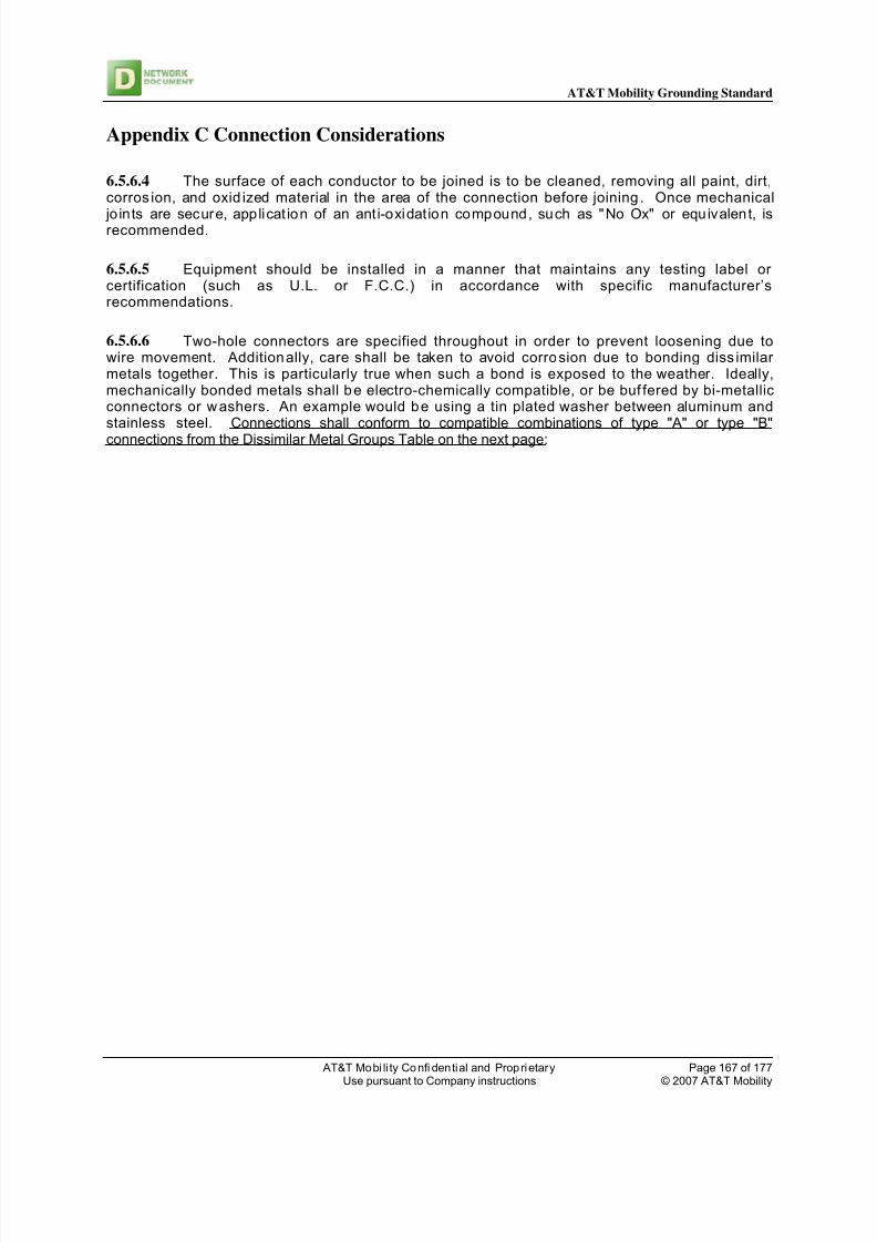
8/11/2019 At & t ND-00071 Rev 3 Grounding Standard
http://slidepdf.com/reader/full/at-t-nd-00071-rev-3-grounding-standard 167/177
AT&T Mobility Grounding Standard
AT&T Mobi li ty Confi dential and Proprietary Page 167 of 177Use pursuant to Company instructions © 2007 AT&T Mobility
Appendix C Connection Considerations
6.5.6.4 The surface of each conductor to be joined is to be cleaned, removing all paint, dirt,corros ion, and oxid ized material in the area of the connection before joining. Once mechanical
jo ints are secure, applicat ion of an ant i-oxidat ion compound, such as "No Ox" or equivalent, isrecommended.
6.5.6.5 Equipment should be installed in a manner that maintains any testing label orcertification (such as U.L. or F.C.C.) in accordance with specific manufacturer’srecommendations.
6.5.6.6 Two-hole connectors are specified throughout in order to prevent loosening due towire movement. Additionally, care shall be taken to avoid corrosion due to bonding diss imilarmetals together. This is particularly true when such a bond is exposed to the weather. Ideally,mechanically bonded metals shall be electro-chemically compatible, or be buf fered by bi-metallicconnectors or washers. An example would be using a tin plated washer between aluminum andstainless steel. Connections shall conform to compatible combinations of type "A" or type "B"
connections from the Dissimilar Metal Groups Table on the next page:

8/11/2019 At & t ND-00071 Rev 3 Grounding Standard
http://slidepdf.com/reader/full/at-t-nd-00071-rev-3-grounding-standard 168/177
AT&T Mobility Grounding Standard
AT&T Mobi li ty Confi dential and Proprietary Page 168 of 177Use pursuant to Company instructions © 2007 AT&T Mobility
Dissimilar Metal Groups
Anodic end (most easi ly corroded)
Group 1 MagnesiumGroup 2 Aluminum, aluminum alloy, zinc, cadmium
Group 3 Carbon steel, iron, lead, tin, tin-lead solder
Group 4 Nickel, chromium, stainless steel
Group 5 Copper, silver, gold, platinum, titanium
Cathodic end (least corroded)
ANODE
WEATHER 1 2 3 4 CATHODE EXPOSURE
Exposed A A 2
Sheltered A A
Housed A A
Exposed C A B 3
Sheltered A B B
Housed A B B
Exposed C A B B 4
Sheltered A A B B
Housed A B B B
Exposed C C C A 5
Sheltered A A A B
Housed A A B B
Key :
A Connection must have a water tight protective finish after a clean metal to metal contact has been
established.
B Exposed bare metal junction allowed, but remainder must have protective finish.
C This connection is NOT allowed.

8/11/2019 At & t ND-00071 Rev 3 Grounding Standard
http://slidepdf.com/reader/full/at-t-nd-00071-rev-3-grounding-standard 169/177
AT&T Mobility Grounding Standard
AT&T Mobi li ty Confi dential and Proprietary Page 169 of 177Use pursuant to Company instructions © 2007 AT&T Mobility

8/11/2019 At & t ND-00071 Rev 3 Grounding Standard
http://slidepdf.com/reader/full/at-t-nd-00071-rev-3-grounding-standard 170/177
AT&T Mobility Grounding Standard
AT&T Mobi li ty Confi dential and Proprietary Page 170 of 177Use pursuant to Company instructions © 2007 AT&T Mobility
Appendix D - Controlling Static Electricity
6.5.6.7 Specific requirements for effectively controlling static electricity will depend on thenature of each work environment. Generally, for equipment protection in the cellularcommunications environment, it is recommended to wear wrist straps connected to ground when
handling static sensitive devices. Also, static-dissipative work surfaces, and groundeddissipative (or conductive) floor sur faces should be utilized in equipment rooms.
6.5.6.8 Storage areas should contain grounded cabinets providing physical separation andhigh-density, vertical storage on grounded permanently static-dissipative shelves. Ground pointsfor wrist straps (banana plugs - typical) should be provided. Wrist strap testers or groundmonitors are recommended to check overall integrity and continuit y prior to each use.
6.5.6.9 The most critical point for effective static control is to make it an integral part ofongoing operations and maintenance. It must be an integrated process providing protectionduring all phases of the maintenance cycle (i.e., handling, transportation, and storage). Goodhousekeeping in areas where static sensitive devices will reside helps to control static build-up.
Common items such as polystyrene (foam) cups and plastic sheet protectors generate and holdsignificant static charges that generally will not drain to an available ground. Items such as thisshould be eliminated from the workplace whenever possible.

8/11/2019 At & t ND-00071 Rev 3 Grounding Standard
http://slidepdf.com/reader/full/at-t-nd-00071-rev-3-grounding-standard 171/177

8/11/2019 At & t ND-00071 Rev 3 Grounding Standard
http://slidepdf.com/reader/full/at-t-nd-00071-rev-3-grounding-standard 172/177
AT&T Mobility Grounding Standard
AT&T Mobi li ty Confi dential and Proprietary Page 172 of 177Use pursuant to Company instructions © 2007 AT&T Mobility
Appendix E - Checklist
6.5.7 General Checklist
6.5.7.1 This section of the Grounding Standard is designed to function as a groundingchecklist for both initial installations and recurring inspections or audits. If copies are made ofthis section, they may serve as the actual worksheets. Space is provided at the end of thissection for comments. Indicate compliance by checking the boxes.
6.5.8 Exterior Ground Ring System
Test report from previous inspection (resistance test) available for comparison. The ring is No. 2 AWG solid tinned copper wire. The exterior ground ring totally encircles the building and tower. The ring is buried 6“below the frost line or 18 inches, whichever is greatest. The ring is spaced 2 feet minimum from the building/tower foundation. All ground ring connections buried in earth are parallel, exothermically welded connections.
Clamp connections are prohibited. Ground rods are a minimum of 5/8 inches in diameter and at least 8 feet long. The driven ground rods are copper clad steel (copperweld). Steel rods, bare or galvanized, or
covered with copper tubing, or hollow core pipes of any type shall NOT be used as driven groundrods.
Ground rods have been driven so that the top of the rods are at 18 inches below grade or 6”below front line. In hard or rocky earth conditions, core drilling and fill has been provided to allowfor full length driven ground rods. The full length of the ground rod shall be used in allcircumstances.
Driven ground rods are bonded to the buried ground ring by means of a "T" type exothermic weld. Ground rods are installed so that the tops are not 'mushroomed'. Inspection sleeves (fabricated from white PVC plastic or concrete) are provided at points along
the ring that allows access for connection, inspection, and periodic ground resistance checks. All external metal objects are directly bonded (exothermically welded where practical) to the
buried ground ring. This includes buried, earth supported, and building mounted metal objects. All environmentally exposed mechanical connections, such as two-hole connectors, are treated
with a protective, anti-oxidant coating. All exothermic welds on galvanized surfaces are sprayed with galvanizing paint. All mechanical connections are made using two-hole connectors with stainless steel or brass
hardware, including the set screw. For guy anchored towers: Each guy wire is bonded to the buried ground ring. Each guy anchor has a buried ground ring around it with at least two driven ground rods. The lowest guy wire turnbuckle has a No. 2 conductor jumpered across it. One bond wire is run directly from the buried ground ring to each external cable entry port ground
bar. These bonds are primary bonds and should be No. 2 AWG bare tinned solid copper wireextended from an exothermic connection at the buried ground ring to the external cable entry portground bar, and connected there by exothermic welding. Wire shall be secured to the building
every 2 feet (minimum) with non-degrading fasteners.
6.5.9 The Interior Ground Ring System For Cell Sites
An interior wire totally encircles the periphery of the equipment area. The interior ground ring wire is constructed of No. 2 AWG stranded type THW green insulated
wire. No other color of insulation is allowed. The interior ground ring is supported from the walls, above the frames, using standoffs at
approximately 24 inch intervals.
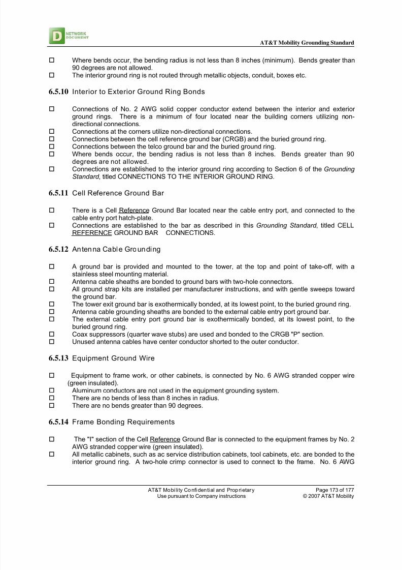
8/11/2019 At & t ND-00071 Rev 3 Grounding Standard
http://slidepdf.com/reader/full/at-t-nd-00071-rev-3-grounding-standard 173/177
AT&T Mobility Grounding Standard
AT&T Mobi li ty Confi dential and Proprietary Page 173 of 177Use pursuant to Company instructions © 2007 AT&T Mobility
Where bends occur, the bending radius is not less than 8 inches (minimum). Bends greater than90 degrees are not allowed.
The interior ground ring is not routed through metallic objects, conduit, boxes etc.
6.5.10 Interior to Exterior Ground Ring Bonds
Connections of No. 2 AWG solid copper conductor extend between the interior and exteriorground rings. There is a minimum of four located near the building corners utilizing non-directional connections.
Connections at the corners utilize non-directional connections. Connections between the cell reference ground bar (CRGB) and the buried ground ring. Connections between the telco ground bar and the buried ground ring. Where bends occur, the bending radius is not less than 8 inches. Bends greater than 90
degrees are not allowed. Connections are established to the interior ground ring according to Section 6 of the Grounding
Standard , titled CONNECTIONS TO THE INTERIOR GROUND RING.
6.5.11 Cell Reference Ground Bar
There is a Cell Reference Ground Bar located near the cable entry port, and connected to thecable entry port hatch-plate.
Connections are established to the bar as described in this Grounding Standard , titled CELLREFERENCE GROUND BAR CONNECTIONS.
6.5.12 Antenna Cable Grounding
A ground bar is provided and mounted to the tower, at the top and point of take-off, with astainless steel mounting material.
Antenna cable sheaths are bonded to ground bars with two-hole connectors. All ground strap kits are installed per manufacturer instructions, and with gentle sweeps toward
the ground bar. The tower exit ground bar is exothermically bonded, at its lowest point, to the buried ground ring. Antenna cable grounding sheaths are bonded to the external cable entry port ground bar. The external cable entry port ground bar is exothermically bonded, at its lowest point, to the
buried ground ring. Coax suppressors (quarter wave stubs) are used and bonded to the CRGB "P" section. Unused antenna cables have center conductor shorted to the outer conductor.
6.5.13 Equipment Ground Wire
Equipment to frame work, or other cabinets, is connected by No. 6 AWG stranded copper wire(green insulated).
Aluminum conductors are not used in the equipment grounding system.
There are no bends of less than 8 inches in radius. There are no bends greater than 90 degrees.
6.5.14 Frame Bonding Requirements
The "I" section of the Cell Reference Ground Bar is connected to the equipment frames by No. 2 AWG stranded copper wire (green insulated).
All metallic cabinets, such as ac service distribution cabinets, tool cabinets, etc. are bonded to theinterior ground ring. A two-hole crimp connector is used to connect to the frame. No. 6 AWG

8/11/2019 At & t ND-00071 Rev 3 Grounding Standard
http://slidepdf.com/reader/full/at-t-nd-00071-rev-3-grounding-standard 174/177
AT&T Mobility Grounding Standard
AT&T Mobi li ty Confi dential and Proprietary Page 174 of 177Use pursuant to Company instructions © 2007 AT&T Mobility
(min.) stranded copper wire (green insulated) is used. Metal battery stands are bonded to the interior ground ring with No. 6 AWG stranded copper wire
(green insulated). A two-hole crimp connector is used. Electrical and mechanical units with associated grilles and duct work are bonded to the interior
ground ring.
All conduits, pipes, and duct work passing across or near the interior ground ring are bonded tothe interior ground ring. Conduits and pipe bond grounding connections are made with a UL approved grounding clamp. There are no exothermic welds on any conduits (inside or outside the communications location).
6.5.15 Ai r Terminals
Where a tower or larger building or obstacle does not offer a "zone of protection", air terminals forlightning protection are provided on the structure housing the communications equipment.
If the entire structure requires a lightning protection air terminal system, it is UL Master Labeled.
6.5.16 Identification Tags / Labels
Each ground conductor terminating on any ground bar has an identification tag attached at eachend that identifies its origin and destination.
Each ground bar is labeled.
6.5.17 Surge Suppressor (TVSS)
The surge suppressor (TVSS) meets the performance specifications of the Grounding Standard .
The surge suppressor (TVSS) is located within 10 feet of the ground-neutral bond, or
ground-neutral protection is required. The surge arrester (TVSS) leads are as short as possible, with minimal bends.
6.5.18 Telecommunications Protection A transient protector is provided on each line. Telecommunications circuits are grounded to the telco ground bar. Telco ground bar is installed and labeled. Telco ground bar is bonded to the buried ground ring. Telco ground bar is bonded to the cell reference ground bar. The telco ground bar is located as close as possible to the physical ends of the entrance cable
shields, towards entry-side of the building. The telco ground bar is insulated from its mounting surface. All leads are tagged with permanent cable labels. Fiber optic telecommunications metallic sheath or strength conductors are grounded to the telco
fiber ground bar.
6.5.19 Roof Top Sites
Grounding and lightning protection is provided in accordance with the Grounding Standard .
6.5.20 Switching Equipment Grounding Features
There exists a single ground bar designated as the isolated ground bar (IGB).

8/11/2019 At & t ND-00071 Rev 3 Grounding Standard
http://slidepdf.com/reader/full/at-t-nd-00071-rev-3-grounding-standard 175/177
AT&T Mobility Grounding Standard
AT&T Mobi li ty Confi dential and Proprietary Page 175 of 177Use pursuant to Company instructions © 2007 AT&T Mobility
The IGB is a copper bar mounted on insulated supports, and physically located inside the isolatedground zone (IGZ) associated with the electronic switch ground system.
The IGB is bonded via the ground window bar to the "I" section of the master ground bar (MGB)via a 2/0 (minimum) or larger wire, engineered for the particular switch.
The resistance of the IGB to MGB bond does not exceed .005 ohms.
There exists a method for continuously monitoring the grounding integrity. If a raised floor is utilized, the steel pedestals are interconnected (20' x 20' grid) with a No. 2
AWG stranded conductor and connected to the "P" section of the MGB.
6.5.21 The following connections are insulated from the integrated ground plane andconnected to the IGB:
Bond to the MGB, via the GWB. Switch equipment grounds (including channel banks). Cable tray system (if insulated from the structure). Distribution frame (if within the IGZ) All other metallic objects that enter or leave the IGZ. The primary ground bar for the site is designated as the master ground bar (MGB). The MGB is a copper bar typically 48 inches long, 1/4 inch thick, and 4 inches wide. It is
insulated from its support and physically located near the cable entrance and an entrance point ofthe external earth ground.
The MGB is designated with zones for connection of surge producers "P", surgeabsorbers "A", non-isolated ground zones "N", and isolated ground zones "I".
6.5.22 Connections to the MGB are as specified below and in the Details: Section " P"Surge Producer
Cell Reference Ground Bar. Generator Framework (if available) Telco Ground Bar Distribution frame ground (CDF) Standby power equipment frame work. Commercial power neutral (AC MGN). Fiber Ground Bar. Power Room Ground Bar. 48V Return bar from power plant.
6.5.23 Section " A" Surge Absorber
Building structural steel or rebar. Buried ground ring. Cold water pipe. Interior ground ring.
6.5.24 Section "N" Non-isolated ground plane (integrated ground plane)
Miscellaneous non-isolated ground plane equipment. Lighting system.
6.5.25 Section " I" Isolated ground plane (IGZ)
Isolated ground bar (IGB) Other isolated ground zones.
6.5.26 Isolation of Communications Equipment)
Anchor bolts are used with an appropriate insulator separating the bolt heads from frame metal.

8/11/2019 At & t ND-00071 Rev 3 Grounding Standard
http://slidepdf.com/reader/full/at-t-nd-00071-rev-3-grounding-standard 176/177
AT&T Mobility Grounding Standard
AT&T Mobi li ty Confi dential and Proprietary Page 176 of 177Use pursuant to Company instructions © 2007 AT&T Mobility
A sheet of insulating material is placed between the frames and the floor. Superstructure support brackets have insulators on top to isolate the IGZ plane. If conductive conduits are used, they pass through the ground window and are bonded to the
GWB, and are insulated for the remainder of the run. Conduits connected to switch IGZ equipment and supported from uni-strut lighting support
channels are insulated by means of fiber sheeting wrapped around the conduit at points ofsupport. Alternately, non-conductive PVC conduit may be used. All AC receptacles within the IGZ comply with NEC 250-74, Exception 4. This exception provides
for an insulated grounded conductor. This grounding conductor (green wire) connects to theGWB.
6.5.27 (Lighting System Components)
Unistrut channel support network - The support channels are joined to the integrated
ground plane. A ground path is assumed to exist through any metallic interconnection ofchannels, except fluorescent lighting fixture runs. Where such metallic interconnection
does not exist, isolated channels, or groups of channels, are bonded with No. 6 AWG
wire as required to from the channel network into an inter-conductive unit.
The unistrut channel network is bonded with No. 6 AWG wire to the MGB. Equipment grounding of fixtures via continuity through raceways - The use of an AC grounding
conductor in parallel with the raceway is considered to be essential. When the ballast is groundedby an AC equipment ground (EG) conductor, the fixture enclosure is considered to be adequatelygrounded.
Emergency lighting - The boxes and conduit are considered as part of the integrated groundplane and are kept separate from the components of the switch ground plane.
6.5.28 Cable Sheathing Ground
Telephone cable shields entering the building are grounded to the telco ground bar. Fiber cable shield entering the building are grounded to the fiber ground bar. The telco ground bar and the fiber ground bar are located as close as possible to the physical
ends of the entrance cable shields, towards entry-side of the building.
The telco ground bar and fiber ground bar are insulated from its mounting surface. The telco ground bar and fiber ground bar are bonded to the MGB, (Section "P"). All leads are tagged with permanent cable labels. The telco and fiber ground bars are each individually bonded to the buried ground ring. The telco and fiber ground bars are installed and labeled.
6.5.29 Path Inductance)
Where possible, telecommunications cables and power feeds entering equipment areas are runthrough at least ten feet of metallic conduit, or against grounded metal surfaces.
6.5.30 IGZ Proximity Bond ing
Air ducts, electrical conduit, metal piping, and other components of the building complex are
assumed to be part of the integrated ground plane without deliberate bonding. When such
members are in close proximity with members of an isolated ground plane, they shall be bonded
to the GWB. Generally, it is expected that bonding of such objects shall be by extending a bond
wire to other bond wires having access to the GWB.

8/11/2019 At & t ND-00071 Rev 3 Grounding Standard
http://slidepdf.com/reader/full/at-t-nd-00071-rev-3-grounding-standard 177/177
AT&T Mobility Grounding Standard
6.5.31 Connection Considerations
6.5.31.1 Two-hole connectors are specified throughout in order to prevent loosening due towire movement. Additionally, care should be taken to avoid corrosion due to bonding dissimilarmetals together.
Connections conform to compatible combinations of type "A" or type "B" connections from thetable titled DISSIMILAR METAL GROUPS, found in Section 17 of the Grounding Standard .
6.5.32 Controlling Static Electricity
Wrist straps (testing and monitoring devices) are available for use . Static-dissipative work surfaces, and grounded dissipative (or conductive) floor surfaces are
provided in equipment rooms. Housekeeping promotes a static free environment.