at-sbx908 gen2 switch - allied telesis · 613-002443 rev. a at-sbx908 gen2 switch advanced layer 3+...
TRANSCRIPT
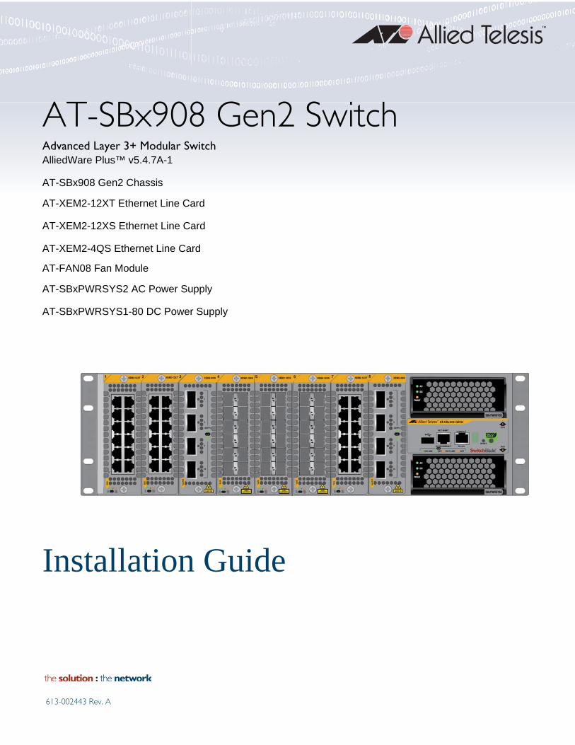
AT-SBx908 Gen2 SwitchAdvanced Layer 3+ Modular SwitchAlliedWare Plus™ v5.4.7A-1
AT-SBx908 Gen2 Chassis
AT-XEM2-12XT Ethernet Line Card
AT-XEM2-12XS Ethernet Line Card
AT-XEM2-4QS Ethernet Line Card
AT-FAN08 Fan Module
AT-SBxPWRSYS2 AC Power Supply
AT-SBxPWRSYS1-80 DC Power Supply
Installation Guide
613-002443 Rev. A

Copyright © 2017 Allied Telesis, Inc.
All rights reserved. No part of this publication may be reproduced without prior written permission from Allied Telesis, Inc.
Allied Telesis, VCStack, and the Allied Telesis logo are trademarks of Allied Telesis, Incorporated. All other product names, company names, logos or other designations mentioned herein are trademarks or registered trademarks of their respective owners.
Allied Telesis, Inc. reserves the right to make changes in specifications and other information contained in this document without prior written notice. The information provided herein is subject to change without notice. In no event shall Allied Telesis, Inc. be liable for any incidental, special, indirect, or consequential damages whatsoever, including but not limited to lost profits, arising out of or related to this manual or the information contained herein, even if Allied Telesis, Inc. has been advised of, known, or should have known, the possibility of such damages.
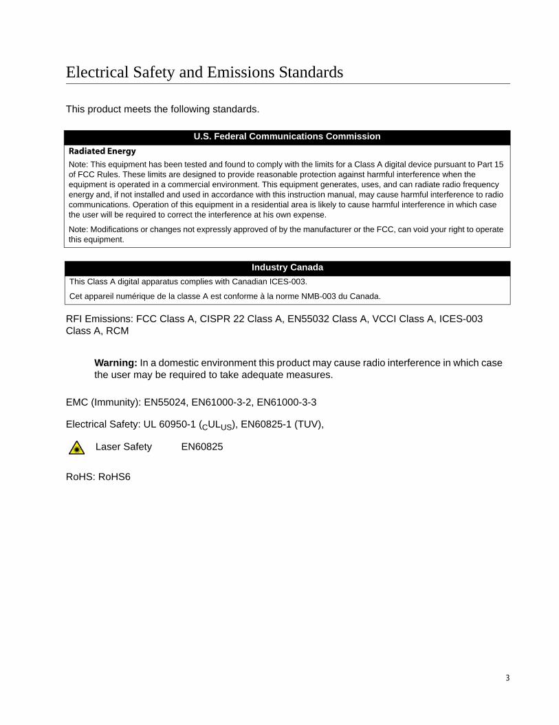
Electrical Safety and Emissions Standards
This product meets the following standards.
RFI Emissions: FCC Class A, CISPR 22 Class A, EN55032 Class A, VCCI Class A, ICES-003 Class A, RCM
EMC (Immunity): EN55024, EN61000-3-2, EN61000-3-3
Electrical Safety: UL 60950-1 (CULUS), EN60825-1 (TUV),
RoHS: RoHS6
U.S. Federal Communications Commission
Radiated Energy
Note: This equipment has been tested and found to comply with the limits for a Class A digital device pursuant to Part 15 of FCC Rules. These limits are designed to provide reasonable protection against harmful interference when the equipment is operated in a commercial environment. This equipment generates, uses, and can radiate radio frequency energy and, if not installed and used in accordance with this instruction manual, may cause harmful interference to radio communications. Operation of this equipment in a residential area is likely to cause harmful interference in which case the user will be required to correct the interference at his own expense.
Note: Modifications or changes not expressly approved of by the manufacturer or the FCC, can void your right to operate this equipment.
Industry Canada
This Class A digital apparatus complies with Canadian ICES-003.
Cet appareil numérique de la classe A est conforme à la norme NMB-003 du Canada.
Warning: In a domestic environment this product may cause radio interference in which case the user may be required to take adequate measures.
Laser Safety EN60825
3

Translated Safety Statements
Important: Safety statements that have the symbol are translated into multiple languages in the Translated Safety Statements document at www.alliedtelesis.com/support.
4
Contents
Preface ...............................................................................................................................................................................13Document Conventions .......................................................................................................................................................14Contacting Allied Telesis .....................................................................................................................................................15
Chapter 1: Overview ........................................................................................................................................................ 17Overview..............................................................................................................................................................................18AT-SBx908 Gen2 Chassis...................................................................................................................................................21Ethernet Line Cards.............................................................................................................................................................22AT-XEM2-12XT Line Card...................................................................................................................................................23AT-XEM2-12XS Line Card...................................................................................................................................................25AT-XEM2-4QS Line Card ....................................................................................................................................................26Management Panel .............................................................................................................................................................27
USB Port ......................................................................................................................................................................27NET MGMT Ethernet Management Port ......................................................................................................................28Console (RS-232) Port .................................................................................................................................................29Switch ID LED ..............................................................................................................................................................29eco-friendly Button .......................................................................................................................................................30Reset Button.................................................................................................................................................................30
Power Supplies....................................................................................................................................................................32AT-FAN08 Units ..................................................................................................................................................................34Specifying Ports in the Command Line Interface.................................................................................................................35
Chapter 2: Beginning the Installation ............................................................................................................................ 37Reviewing Safety Precautions.............................................................................................................................................38Choosing a Site for the Chassis ..........................................................................................................................................43Unpacking the Chassis........................................................................................................................................................44Unpacking AT-SBxPWRSYS2 AC Power Supplies.............................................................................................................49Unpacking AT-SBxPWRSYS1-80 DC Power Supplies .......................................................................................................50
Chapter 3: Installing the Chassis ................................................................................................................................... 51Tools and Material ...............................................................................................................................................................52Adjusting the Equipment Rack Brackets..............................................................................................................................53Installing the Chassis in an Equipment Rack.......................................................................................................................57Installing the Chassis Grounding Wire.................................................................................................................................58Installing AT-SBxPWRSYS2 AC Power Supplies................................................................................................................61Installing AT-SBxPWRSYS1-80 DC Power Supplies ..........................................................................................................65Installing Ethernet Line Cards .............................................................................................................................................69Installing Blank Line Card Slot Covers ................................................................................................................................73Installing the Blank Power Supply Slot Cover......................................................................................................................75Installing the Power Cord Retaining Clips ...........................................................................................................................77
Chapter 4: Powering On the Chassis ............................................................................................................................. 79Verifying the Installation ......................................................................................................................................................80Powering On AT-SBxPWRSYS2 Power Supplies ...............................................................................................................81Powering On AT-SBxPWRSYS1-80 DC Power Supplies....................................................................................................84
Choosing a Method for Attaching the Grounding Wire .................................................................................................86Connecting the Grounding Wire with the Grounding Terminal .....................................................................................86Connecting the Grounding Wire with Bare Wire...........................................................................................................91Choosing a Method for Attaching the Power Wires......................................................................................................93Connecting the DC Power Wires with the Straight Terminals ......................................................................................93Connecting the DC Power Wires with the Right Angle Terminals ..............................................................................100
5
Contents
Connecting Bare DC Power Wires ............................................................................................................................ 107Monitoring the Initialization Processes.............................................................................................................................. 111Verifying the Hardware Operations of the Chassis ........................................................................................................... 114
Starting a Local Management Session...................................................................................................................... 114Verifying the Chassis with the AlliedWare Plus Commands...................................................................................... 115
Chapter 5: Cabling the Networking Ports .................................................................................................................... 117Cabling the 1Gbps or 10Gbps Ports on the AT-XEM2-12XT Line Card ........................................................................... 118Guidelines to Handling SFP, SFP+, and QSFP+ Transceivers ........................................................................................ 119Installing 1GBase SFP or 10GBase SFP+ Transceivers in AT-XEM2-12XS Line Cards ................................................. 120Installing AT-SP10TW Direct Connect Twinax Cables in the AT-XEM2-12XS Switch ..................................................... 123Installing AT-QSFPSR4 or AT-QSFPLR4 Transceivers in QSFP+ Slots ......................................................................... 125Installing AT-QSFPCU Cables in QSFP+ Slots ................................................................................................................ 126
Chapter 6: Replacing Modules ..................................................................................................................................... 129Replacing AT-SBxPWRSYS2 AC Power Supplies ........................................................................................................... 130Replacing AT-SBxPWRSYS1-80 DC Power Supplies...................................................................................................... 134Removing Ethernet Line Cards......................................................................................................................................... 145Replacing AT-FAN08 Modules ......................................................................................................................................... 150
Removing AT-FAN08 Modules.................................................................................................................................. 150Installing AT-FAN08 Modules.................................................................................................................................... 151
Chapter 7: Troubleshooting .......................................................................................................................................... 155
Appendix A: Technical Specifications ......................................................................................................................... 159Physical Specifications ..................................................................................................................................................... 160Environmental Specifications............................................................................................................................................ 162Power Specifications......................................................................................................................................................... 163Certifications ..................................................................................................................................................................... 165Port Pinouts ...................................................................................................................................................................... 166
6
Figures
Figure 1: Front Panel of the AT-SBx908 Gen2 Chassis .......................................................................................................21Figure 2: Rear Panel of the AT-SBx908 Gen2 Chassis........................................................................................................21Figure 3: AT-SBx908 Gen2 Ethernet Line Cards .................................................................................................................22Figure 4: Management Panel ...............................................................................................................................................27Figure 5: Switch ID LED .......................................................................................................................................................30Figure 6: AT-SBxPWRSYS2 and AT-SBxPWRSYS1-80 Power Supplies ...........................................................................32Figure 7: AT-FAN08 Module.................................................................................................................................................34Figure 8: PORT Parameter in the Command Line Interface.................................................................................................35Figure 9: NEMA 5-20P Plug and Receptacle .......................................................................................................................43Figure 10: AT-SBx908 Gen2 Switch Shipping Box...............................................................................................................44Figure 11: Lifting the Switch from the Shipping Box.............................................................................................................45Figure 12: Removing the Switch from the Protective Shipping Bag. ....................................................................................45Figure 13: Pre-installed Items on the Front and Side Panels ...............................................................................................46Figure 14: Pre-installed Items on the Rear Panel.................................................................................................................47Figure 15: Accessory Kit.......................................................................................................................................................48Figure 16: Items in the Shipping Box for the AT-SBxPWRSYS2 AC Power Supply ............................................................49Figure 17: Items in the Shipping Box for the AT-SBxPWRSYS1-80 DC Power Supply .......................................................50Figure 18: Chassis Orientations in the Equipment Rack ......................................................................................................53Figure 19: Chassis Orientations in the Equipment Rack (Continued) ..................................................................................54Figure 20: Chassis Orientations in the Equipment Rack (Continued) ..................................................................................55Figure 21: Example of Adjusting the Equipment Rack Brackets ..........................................................................................56Figure 22: Securing the Chassis to the Equipment Rack .....................................................................................................57Figure 23: Stripping the Grounding Wire ..............................................................................................................................58Figure 24: Removing the Grounding Lug from the Chassis..................................................................................................59Figure 25: Attaching the Grounding Wire to the Grounding Lug...........................................................................................59Figure 26: Installing the Grounding Lug and Wire ................................................................................................................60Figure 27: Removing the Blank Power Supply Panel from Power Supply Slot B .................................................................62Figure 28: Lifting the Locking Handle on the AT-SBxPWRSYS2 Power Supply ..................................................................62Figure 29: Sliding the AT-SBxPWRSYS2 AC Power Supply into the Chassis .....................................................................63Figure 30: Lowering the Locking Handle on the AT-SBxPWRSYS2 AC Power Supply .......................................................64Figure 31: On/Off Switch on the AT-SBxPWRSYS1-80 DC Power Supply..........................................................................66Figure 32: Loosening the Handle locking Screw on the AT-SBxPWRSYS1-80 DC Power Supply......................................66Figure 33: Lifting the Locking Handle on the AT-SBxPWRSYS1-80 DC Power Supply.......................................................67Figure 34: Inserting the AT-SBxPWRSYS1-80 DC Power Supply .......................................................................................67Figure 35: Lowering the Locking Handle on the AT-SBxPWRSYS1-80 DC Power Supply..................................................68Figure 36: Removing a Blank Line Card Cover ....................................................................................................................69Figure 37: Removing the Ethernet Line Card from the Anti-static Bag.................................................................................70Figure 38: Sliding the Ethernet Line Card into the Slot.........................................................................................................71Figure 39: Seating an Ethernet Line Card in the Chassis.....................................................................................................72Figure 40: Tightening the Two Captive Screws on the Ethernet Line Card..........................................................................72Figure 41: Installing a Blank Slot Cover................................................................................................................................73Figure 42: Tightening the Captive Screws on a Blank Slot Cover ........................................................................................74Figure 43: Lifting the Locking Handle on the Blank Power Supply Slot Cover .....................................................................75Figure 44: Aligning the Blank Power Supply Cover in the Slot .............................................................................................76Figure 45: Lowering the Locking Handle on the Blank Power Supply Slot Cover ................................................................76Figure 46: Installing the Power Cord Retaining Clips ...........................................................................................................77Figure 47: Connecting the AC Power Cord ..........................................................................................................................82Figure 48: Securing the Power Cord with the Retaining Clip................................................................................................82Figure 49: Connecting the Power Cord to an AC Power Source..........................................................................................83
7

Figures
Figure 50: Components on the AT-SBxPWRSYS1-80 DC Power Supply............................................................................85Figure 51: Grounding Wire Terminal.....................................................................................................................................86Figure 52: Stripping the Stranded Grounding Wire...............................................................................................................86Figure 53: Attaching the Stranded Grounding Wire to the Grounding Terminal ...................................................................86Figure 54: On/Off Switch on the AT-SBxPWRSYS1-80 DC Power Supply ..........................................................................87Figure 55: Removing the Nut and Washer from the Grounding Post ...................................................................................88Figure 56: Attaching the Grounding Lug and Wire to the Grounding Post............................................................................89Figure 57: Securing the Grounding Wire ..............................................................................................................................90Figure 58: Stripping the solid or Stranded Grounding Wire ..................................................................................................91Figure 59: Attaching the Bare Grounding Wire to the Grounding Post .................................................................................91Figure 60: Securing the Bare Grounding Wire to the Grounding Post..................................................................................92Figure 61: Power Wire Terminals .........................................................................................................................................93Figure 62: Stripping the Power Wires ...................................................................................................................................94Figure 63: Attaching the Power Wires to the Straight Terminal Lugs ...................................................................................94Figure 64: Opening the Plastic Cover ...................................................................................................................................95Figure 65: Removing the Terminal Screws...........................................................................................................................96Figure 66: Connecting the Positive (+) Power Wire with a Straight Terminal .......................................................................97Figure 67: Connecting the Negative (-) Power Wire with a Straight Terminal ......................................................................98Figure 68: Closing the Plastic Cover over the Terminal Connectors ....................................................................................99Figure 69: Tightening the Handle Locking Screw ...............................................................................................................100Figure 70: Stripping the Power Wires .................................................................................................................................101Figure 71: Attaching the Power Wires to the Right Angle Terminal Lugs ...........................................................................101Figure 72: Removing the Plastic Cover ..............................................................................................................................102Figure 73: Removing the Terminal Screws.........................................................................................................................103Figure 74: Connecting the Positive (+) Power Wire with a Right Angle Terminal...............................................................104Figure 75: Connecting the Negative (-) Power Wire with a Right Angle Terminal ..............................................................105Figure 76: Tightening the Handle Locking Screw ...............................................................................................................106Figure 77: Stripping Solid or Stranded DC Power Wires ....................................................................................................107Figure 78: Connecting the Positive Wire With Bare Wire ...................................................................................................108Figure 79: Connecting the Negative Lead Wire with Bare Wire..........................................................................................109Figure 80: Switch Initialization Messages...........................................................................................................................111Figure 81: Switch Initialization Messages (Continued) .......................................................................................................112Figure 82: Switch Initialization Messages (Continued) .......................................................................................................113Figure 83: Connecting the Management Cable to the Console RS-232 Port .....................................................................114Figure 84: SHOW CARD Command...................................................................................................................................116Figure 85: Installing an SFP Transceiver............................................................................................................................120Figure 86: Removing the Dust Cover from an SFP or SFP+ Transceiver ..........................................................................121Figure 87: Positioning the SFP or SFP+ Handle in the Upright Position ............................................................................121Figure 88: Connecting a Fiber Optic Cable to an SFP or SFP+ Transceiver .....................................................................122Figure 89: Installing AT-SP10TW Cables in the AT-XEM2-12XS Line Card ......................................................................123Figure 90: Removing the Dust Cover from a Slot on the AT-XEM2-4QS Line Card...........................................................126Figure 91: Sliding the AT-QSFPCU Cable into the Slot......................................................................................................127Figure 92: Disconnecting the AC Power Cord from the Power Source ..............................................................................131Figure 93: Disconnecting the AC Power Cord from the Chassis ........................................................................................131Figure 94: Lifting the Locking Handle on the AT-SBxPWRSYS2 AC Power Supply ..........................................................132Figure 95: Removing the AT-SBxPWRSYS2 AC Power Supply ........................................................................................133Figure 96: Loosening the Screw on the Locking Handle ....................................................................................................134Figure 97: Opening the Plastic Window over the Terminal Block .......................................................................................135Figure 98: Removing the Negative Lead Wire....................................................................................................................136Figure 99: Removing the Positive Lead Wire from the Terminal Block...............................................................................137Figure 100: Reinstalling the Screws on the Positive and Negative Terminals....................................................................138Figure 101: Closing the Plastic Cover.................................................................................................................................139Figure 102: Removing the Grounding Wire ........................................................................................................................140Figure 103: Reinstalling the Nut and Washer on the Grounding Post ................................................................................141Figure 104: Lifting the Locking Handle and Removing the Power Supply ..........................................................................142Figure 105: Installing the Blank Power Supply Slot Cover..................................................................................................143Figure 106: Lowering the Locking Handle on the Power Supply Slot Cover ......................................................................144Figure 107: Loosening the Screws on the Ethernet Line Card ...........................................................................................146Figure 108: Disconnecting an Ethernet Line Card from the Chassis ..................................................................................147Figure 109: Sliding an Ethernet Line Card from the Chassis..............................................................................................148
8

AT-SBx908 Gen2 Switch Installation Guide
Figure 110: Placing the Ethernet Line Card in its Anti-static Bag.......................................................................................149Figure 111: Loosening the Screws on the AT-FAN08 Module ...........................................................................................150Figure 112: Disconnecting the AT-FAN08 Module from the Chassis .................................................................................151Figure 113: Aligning the AT-FAN08 Module in the Chassis Slot ........................................................................................152Figure 114: Seating the AT-FAN08 Module on the Connector in the Chassis ...................................................................152Figure 115: Tightening the Two Captive Screws on the AT-FAN08 Module ......................................................................153Figure 116: Pin Layout (Front View) of the 1Gbps or 10Gbps Ports on the AT-XEM2-12XT Line Card ............................166
9

Figures
10
Tables
11
Table 1: Features of the AT-SBx908 Gen2 Chassis ............................................................................................................18Table 2: Twisted Pair Ports on the AT-XEM2-12XT Line Card ............................................................................................23Table 3: Link and Activity LEDs on the AT-XEM2-12XT Line Card .....................................................................................23Table 4: Link and Activity LEDs on the AT-XEM2-12XS Line Card .....................................................................................25Table 5: Link and Activity Status LEDs for the AT-XEM2-4QS Line Card ...........................................................................26Table 6: Twisted Pair Cable for the NET MGMT Port on the Management Panel ..............................................................28Table 7: NET MGMT Port LED ............................................................................................................................................29Table 8: PORT Parameter Format .......................................................................................................................................35Table 9: Product Dimensions .............................................................................................................................................160Table 10: Product Weights ................................................................................................................................................160Table 11: Ventilation Requirements ...................................................................................................................................161Table 12: Environmental Specifications .............................................................................................................................162Table 13: AC Voltage and Frequency Requirements ........................................................................................................163Table 14: DC Voltage Requirements .................................................................................................................................163Table 15: Maximum Power Consumption (Watts) .............................................................................................................163Table 16: Typical Power Savings in eco-friendly Mode (Watts) ........................................................................................163Table 17: Maximum Power Supply Efficiency (Based on 100V Input Voltage) .................................................................164Table 18: Heat Dissipation (British Thermal Units/Hour) ...................................................................................................164Table 19: Product Certifications .........................................................................................................................................165Table 20: Pin Signals for 1Gbps or 10Gbps ......................................................................................................................166Table 21: RJ-45 Pin Signals for the Console Port on the Management Panel ..................................................................167Table 22: RJ-45 Pin Signals for 10 or 100Mbps for the NET MGMT Port on the Management Panel ..............................167

Tables
12
Preface
This guide contains the installation instructions for the AT-SBx908 Gen2 advanced modular, Layer 3 Ethernet switch. This preface contains the following sections:
“Document Conventions” on page 14
“Contacting Allied Telesis” on page 15
13
Preface
Document Conventions
This document uses the following conventions:
NoteNotes provide additional information.
CautionCautions inform you that performing or omitting a specific action may result in equipment damage or loss of data.
WarningWarnings inform you that performing or omitting a specific action may result in bodily injury.
14

AT-SBx908 Gen2 Switch Installation Guide
Contacting Allied Telesis
If you need assistance with this product, you may contact Allied Telesis technical support by going to the Support & Services section of the Allied Telesis web site at www.alliedtelesis.com/support. You can find links for the following services on this page:
24/7 Online Support — Enter our interactive support center to search for answers to your product questions in our knowledge database, to check support tickets, to learn about RMAs, and to contact Allied Telesis technical experts.
USA and EMEA phone support — Select the phone number that best fits your location and customer type.
Hardware warranty information — Learn about Allied Telesis warranties and register your product online.
Replacement Services — Submit a Return Merchandise Authorization (RMA) request via our interactive support center.
Documentation — View the most recent installation and user guides, software release notes, white papers, and data sheets for your products.
Software Downloads — Download the latest software releases for your managed products.
For sales or corporate information, go to www.alliedtelesis.com/purchase and select your region.
15

Preface
16
Chapter 1
Overview
The chapter contains the following sections:
“Overview” on page 18
“AT-SBx908 Gen2 Chassis” on page 21
“Ethernet Line Cards” on page 22
“AT-XEM2-12XT Line Card” on page 23
“AT-XEM2-12XS Line Card” on page 25
“AT-XEM2-4QS Line Card” on page 26
“Management Panel” on page 27
“Power Supplies” on page 32
“AT-FAN08 Units” on page 34
“Specifying Ports in the Command Line Interface” on page 35
17
Chapter 1: Overview
Overview
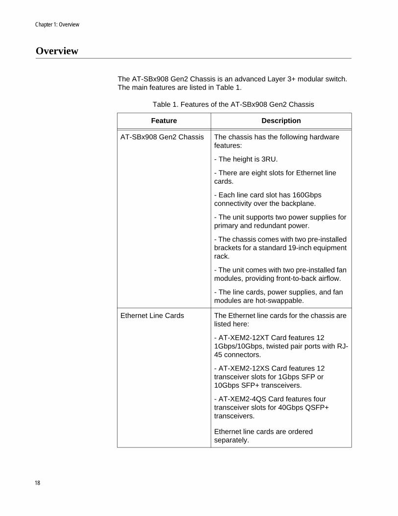
The AT-SBx908 Gen2 Chassis is an advanced Layer 3+ modular switch. The main features are listed in Table 1.
Table 1. Features of the AT-SBx908 Gen2 Chassis
Feature Description
AT-SBx908 Gen2 Chassis The chassis has the following hardware features:
- The height is 3RU.
- There are eight slots for Ethernet line cards.
- Each line card slot has 160Gbps connectivity over the backplane.
- The unit supports two power supplies for primary and redundant power.
- The chassis comes with two pre-installed brackets for a standard 19-inch equipment rack.
- The unit comes with two pre-installed fan modules, providing front-to-back airflow.
- The line cards, power supplies, and fan modules are hot-swappable.
Ethernet Line Cards The Ethernet line cards for the chassis are listed here:
- AT-XEM2-12XT Card features 12 1Gbps/10Gbps, twisted pair ports with RJ-45 connectors.
- AT-XEM2-12XS Card features 12 transceiver slots for 1Gbps SFP or 10Gbps SFP+ transceivers.
- AT-XEM2-4QS Card features four transceiver slots for 40Gbps QSFP+ transceivers.
Ethernet line cards are ordered separately.
18
AT-x908 Gen2 Switch Installation Guide
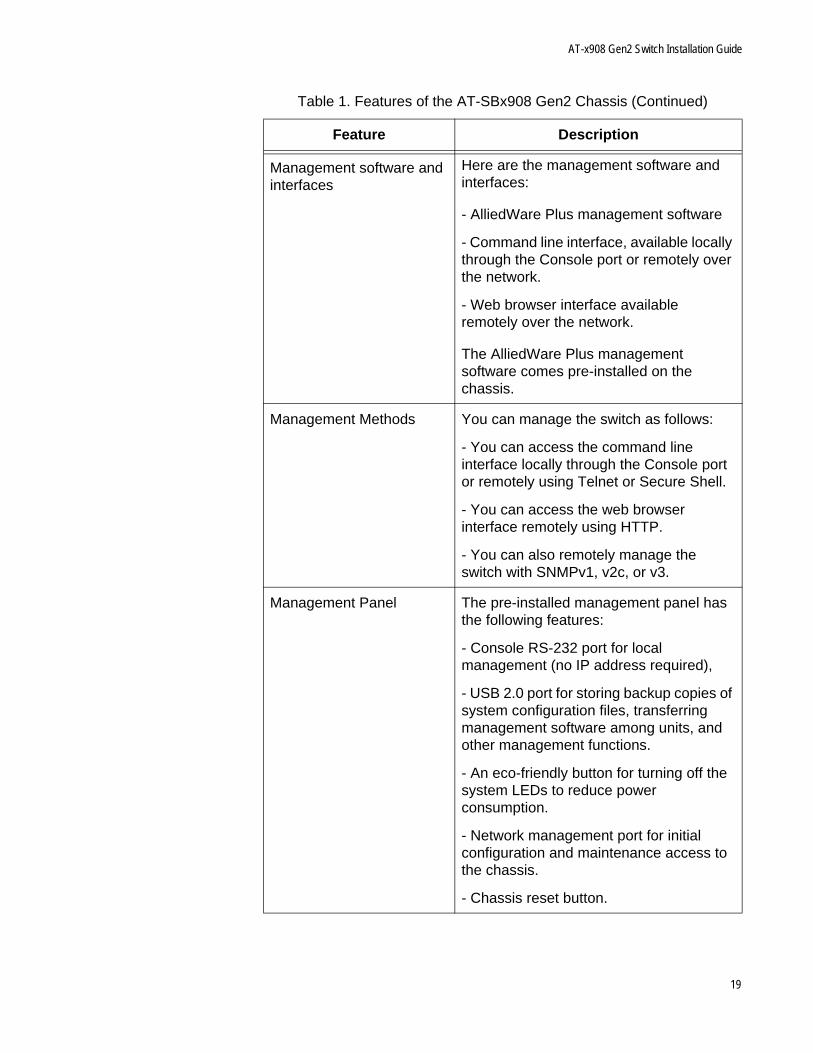
Management software and interfaces
Here are the management software and interfaces:
- AlliedWare Plus management software
- Command line interface, available locally through the Console port or remotely over the network.
- Web browser interface available remotely over the network.
The AlliedWare Plus management software comes pre-installed on the chassis.
Management Methods You can manage the switch as follows:
- You can access the command line interface locally through the Console port or remotely using Telnet or Secure Shell.
- You can access the web browser interface remotely using HTTP.
- You can also remotely manage the switch with SNMPv1, v2c, or v3.
Management Panel The pre-installed management panel has the following features:
- Console RS-232 port for local management (no IP address required),
- USB 2.0 port for storing backup copies of system configuration files, transferring management software among units, and other management functions.
- An eco-friendly button for turning off the system LEDs to reduce power consumption.
- Network management port for initial configuration and maintenance access to the chassis.
- Chassis reset button.
Table 1. Features of the AT-SBx908 Gen2 Chassis (Continued)
Feature Description
19

Chapter 1: Overview
Power Supplies The chassis can be powered by one or two power supplies. A chassis with two power supplies has power redundancy. Power supplies are ordered separately
Table 1. Features of the AT-SBx908 Gen2 Chassis (Continued)
Feature Description
20
AT-x908 Gen2 Switch Installation Guide
AT-SBx908 Gen2 Chassis
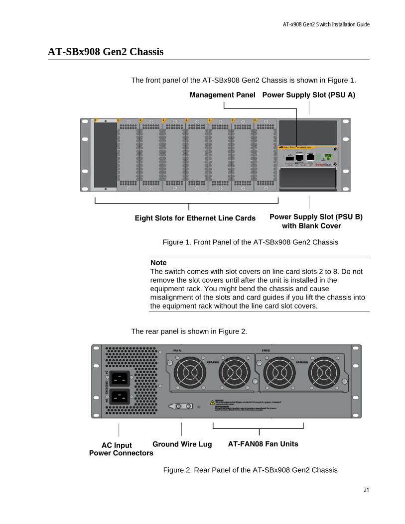
The front panel of the AT-SBx908 Gen2 Chassis is shown in Figure 1.
Figure 1. Front Panel of the AT-SBx908 Gen2 Chassis
NoteThe switch comes with slot covers on line card slots 2 to 8. Do not remove the slot covers until after the unit is installed in the equipment rack. You might bend the chassis and cause misalignment of the slots and card guides if you lift the chassis into the equipment rack without the line card slot covers.
The rear panel is shown in Figure 2.
Figure 2. Rear Panel of the AT-SBx908 Gen2 Chassis
Eight Slots for Ethernet Line Cards
Power Supply Slot (PSU A)
Power Supply Slot (PSU B)with Blank Cover
Management Panel
Ground Wire LugAC InputPower Connectors
AT-FAN08 Fan Units
21
Chapter 1: Overview
Ethernet Line Cards
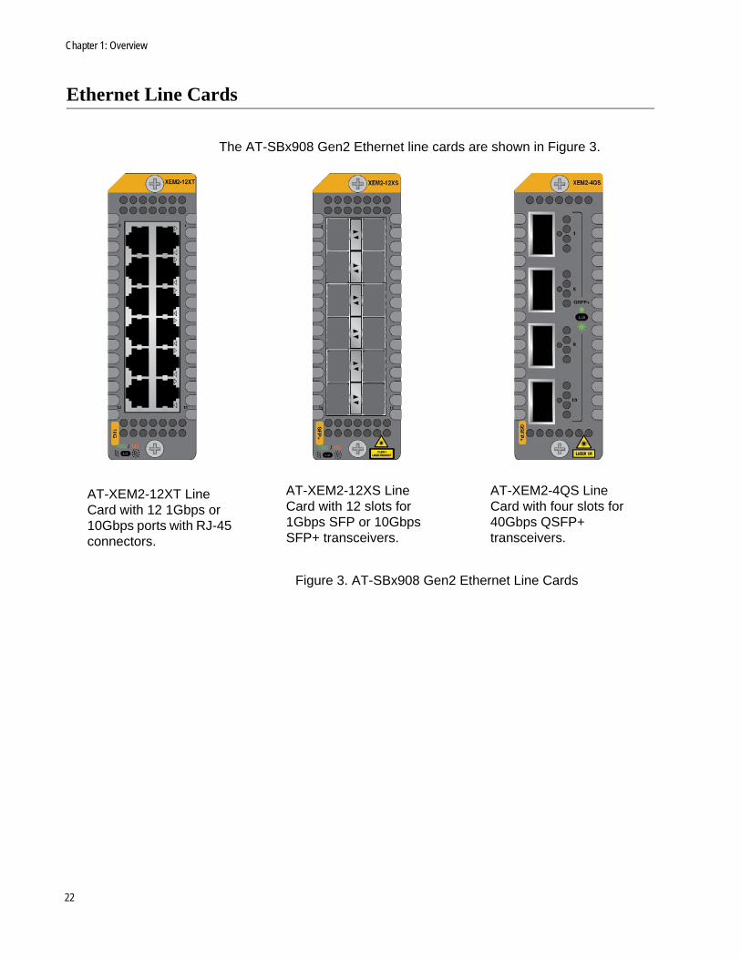
The AT-SBx908 Gen2 Ethernet line cards are shown in Figure 3.
Figure 3. AT-SBx908 Gen2 Ethernet Line Cards
AT-XEM2-12XT Line Card with 12 1Gbps or 10Gbps ports with RJ-45 connectors.
AT-XEM2-12XS Line Card with 12 slots for 1Gbps SFP or 10Gbps SFP+ transceivers.
AT-XEM2-4QS Line Card with four slots for 40Gbps QSFP+ transceivers.
22
AT-x908 Gen2 Switch Installation Guide
AT-XEM2-12XT Line Card
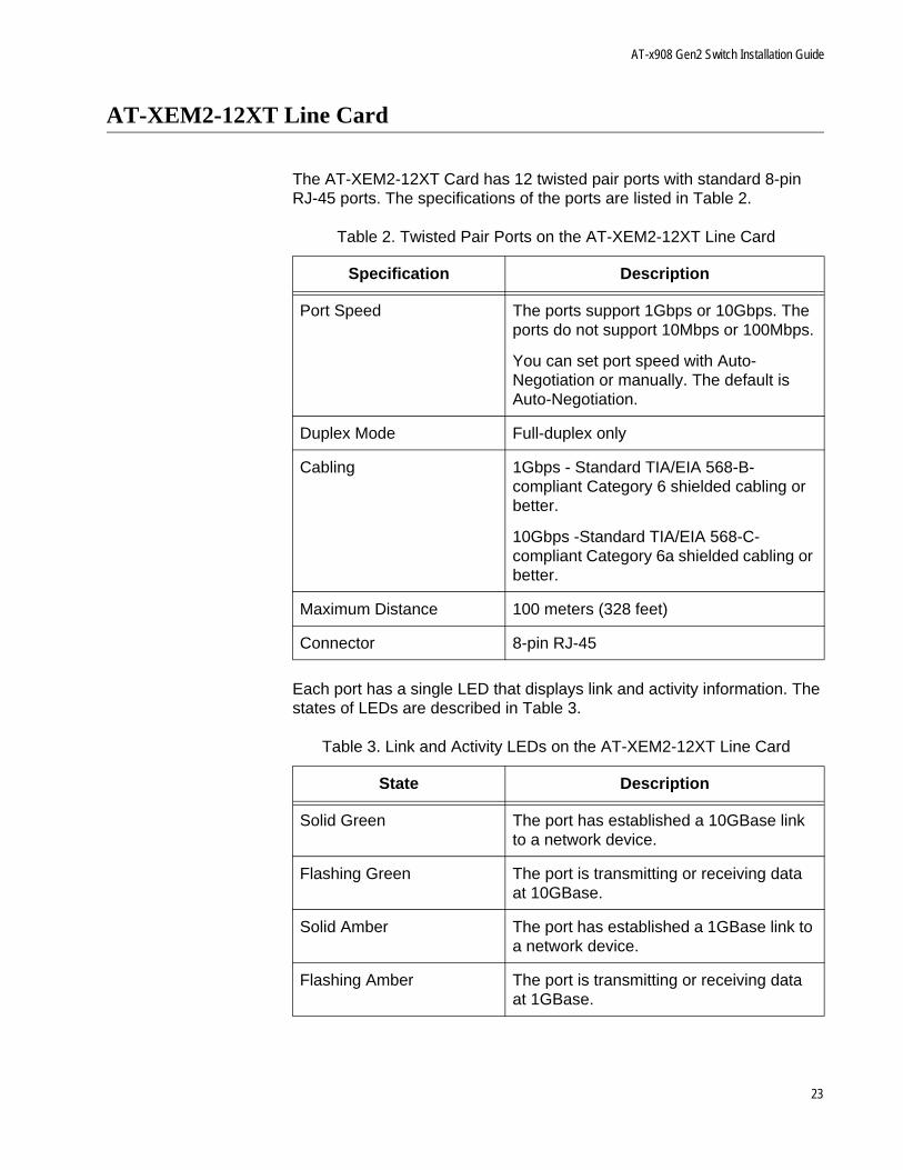
The AT-XEM2-12XT Card has 12 twisted pair ports with standard 8-pin RJ-45 ports. The specifications of the ports are listed in Table 2.
Each port has a single LED that displays link and activity information. The states of LEDs are described in Table 3.
Table 2. Twisted Pair Ports on the AT-XEM2-12XT Line Card
Specification Description
Port Speed The ports support 1Gbps or 10Gbps. The ports do not support 10Mbps or 100Mbps.
You can set port speed with Auto-Negotiation or manually. The default is Auto-Negotiation.
Duplex Mode Full-duplex only
Cabling 1Gbps - Standard TIA/EIA 568-B-compliant Category 6 shielded cabling or better.
10Gbps -Standard TIA/EIA 568-C-compliant Category 6a shielded cabling or better.
Maximum Distance 100 meters (328 feet)
Connector 8-pin RJ-45
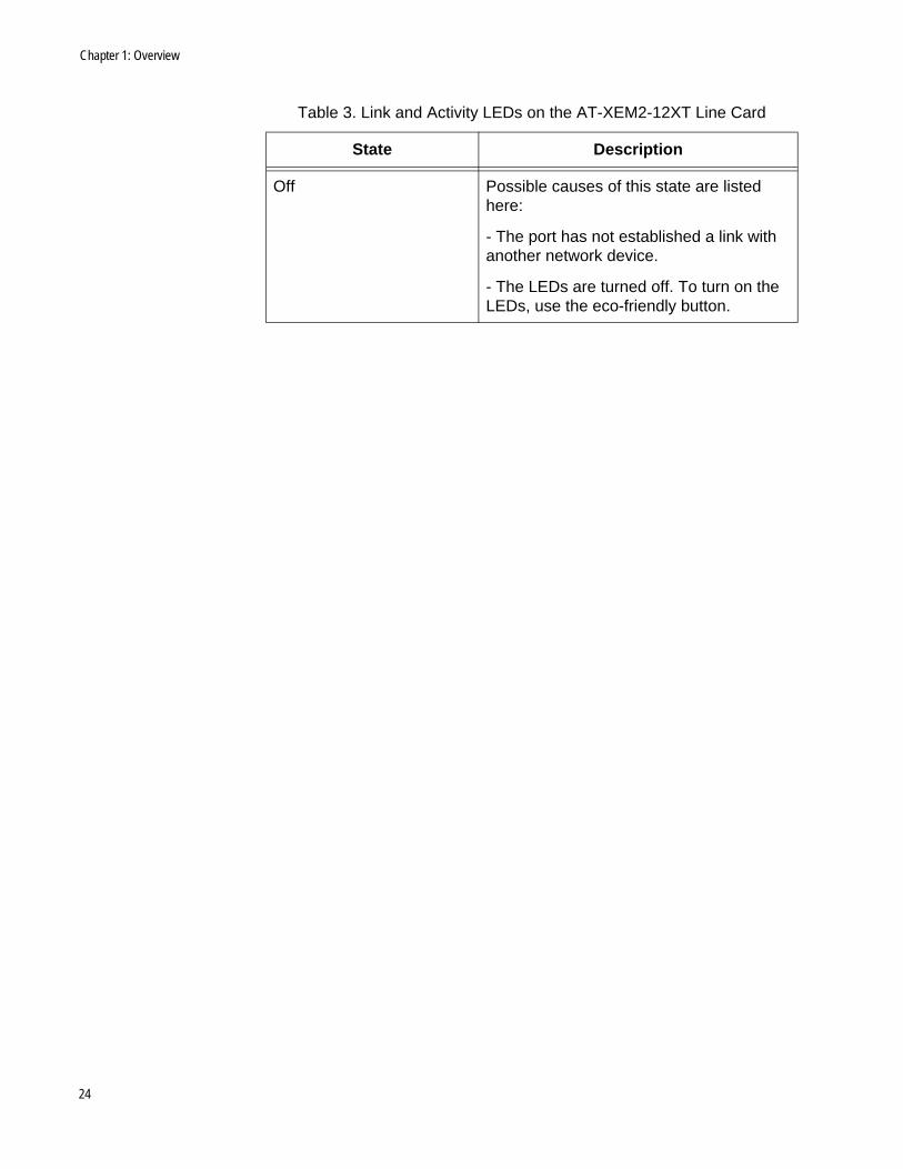
Table 3. Link and Activity LEDs on the AT-XEM2-12XT Line Card
State Description
Solid Green The port has established a 10GBase link to a network device.
Flashing Green The port is transmitting or receiving data at 10GBase.
Solid Amber The port has established a 1GBase link to a network device.
Flashing Amber The port is transmitting or receiving data at 1GBase.
23
Chapter 1: Overview
Off Possible causes of this state are listed here:
- The port has not established a link with another network device.
- The LEDs are turned off. To turn on the LEDs, use the eco-friendly button.
Table 3. Link and Activity LEDs on the AT-XEM2-12XT Line Card
State Description
24
AT-x908 Gen2 Switch Installation Guide
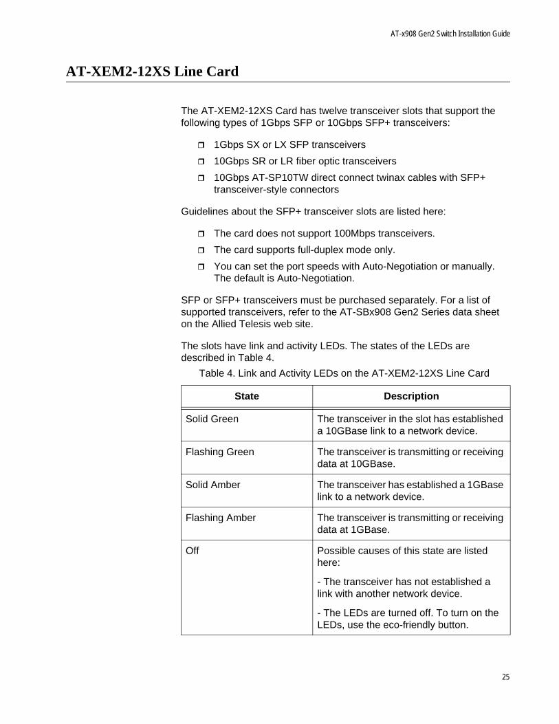
AT-XEM2-12XS Line Card
The AT-XEM2-12XS Card has twelve transceiver slots that support the following types of 1Gbps SFP or 10Gbps SFP+ transceivers:
1Gbps SX or LX SFP transceivers
10Gbps SR or LR fiber optic transceivers
10Gbps AT-SP10TW direct connect twinax cables with SFP+ transceiver-style connectors
Guidelines about the SFP+ transceiver slots are listed here:
The card does not support 100Mbps transceivers.
The card supports full-duplex mode only.
You can set the port speeds with Auto-Negotiation or manually. The default is Auto-Negotiation.
SFP or SFP+ transceivers must be purchased separately. For a list of supported transceivers, refer to the AT-SBx908 Gen2 Series data sheet on the Allied Telesis web site.
The slots have link and activity LEDs. The states of the LEDs are described in Table 4.
Table 4. Link and Activity LEDs on the AT-XEM2-12XS Line Card
State Description
Solid Green The transceiver in the slot has established a 10GBase link to a network device.
Flashing Green The transceiver is transmitting or receiving data at 10GBase.
Solid Amber The transceiver has established a 1GBase link to a network device.
Flashing Amber The transceiver is transmitting or receiving data at 1GBase.
Off Possible causes of this state are listed here:
- The transceiver has not established a link with another network device.
- The LEDs are turned off. To turn on the LEDs, use the eco-friendly button.
25
Chapter 1: Overview
AT-XEM2-4QS Line Card
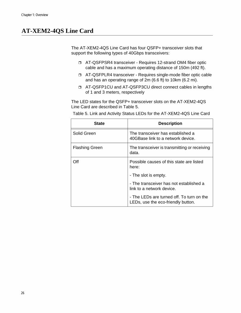
The AT-XEM2-4QS Line Card has four QSFP+ transceiver slots that support the following types of 40Gbps transceivers:
AT-QSFPSR4 transceiver - Requires 12-strand OM4 fiber optic cable and has a maximum operating distance of 150m (492 ft).
AT-QSFPLR4 transceiver - Requires single-mode fiber optic cable and has an operating range of 2m (6.6 ft) to 10km (6.2 mi).
AT-QSFP1CU and AT-QSFP3CU direct connect cables in lengths of 1 and 3 meters, respectively
The LED states for the QSFP+ transceiver slots on the AT-XEM2-4QS Line Card are described in Table 5.
Table 5. Link and Activity Status LEDs for the AT-XEM2-4QS Line Card
State Description
Solid Green The transceiver has established a 40GBase link to a network device.
Flashing Green The transceiver is transmitting or receiving data.
Off Possible causes of this state are listed here:
- The slot is empty.
- The transceiver has not established a link to a network device.
- The LEDs are turned off. To turn on the LEDs, use the eco-friendly button.
26
AT-x908 Gen2 Switch Installation Guide
Management Panel
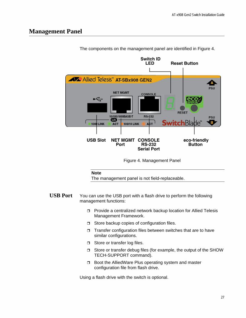
The components on the management panel are identified in Figure 4.
Figure 4. Management Panel
NoteThe management panel is not field-replaceable.
USB Port You can use the USB port with a flash drive to perform the following management functions:
Provide a centralized network backup location for Allied Telesis Management Framework.
Store backup copies of configuration files.
Transfer configuration files between switches that are to have similar configurations.
Store or transfer log files.
Store or transfer debug files (for example, the output of the SHOW TECH-SUPPORT command).
Boot the AlliedWare Plus operating system and master configuration file from flash drive.
Using a flash drive with the switch is optional.
USB Slot NET MGMTPort
CONSOLERS-232
Serial Port
Switch IDLED
eco-friendlyButton
Reset Button
27
Chapter 1: Overview
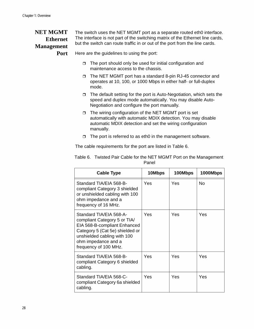
NET MGMTEthernet
ManagementPort
The switch uses the NET MGMT port as a separate routed eth0 interface. The interface is not part of the switching matrix of the Ethernet line cards, but the switch can route traffic in or out of the port from the line cards.
Here are the guidelines to using the port:
The port should only be used for initial configuration and maintenance access to the chassis.
The NET MGMT port has a standard 8-pin RJ-45 connector and operates at 10, 100, or 1000 Mbps in either half- or full-duplex mode.
The default setting for the port is Auto-Negotiation, which sets the speed and duplex mode automatically. You may disable Auto-Negotiation and configure the port manually.
The wiring configuration of the NET MGMT port is set automatically with automatic MDIX detection. You may disable automatic MDIX detection and set the wiring configuration manually.
The port is referred to as eth0 in the management software.
The cable requirements for the port are listed in Table 6.
Table 6. Twisted Pair Cable for the NET MGMT Port on the Management Panel
Cable Type 10Mbps 100Mbps 1000Mbps
Standard TIA/EIA 568-B-compliant Category 3 shielded or unshielded cabling with 100 ohm impedance and a frequency of 16 MHz.
Yes Yes No
Standard TIA/EIA 568-A-compliant Category 5 or TIA/EIA 568-B-compliant Enhanced Category 5 (Cat 5e) shielded or unshielded cabling with 100 ohm impedance and a frequency of 100 MHz.
Yes Yes Yes
Standard TIA/EIA 568-B-compliant Category 6 shielded cabling.
Yes Yes Yes
Standard TIA/EIA 568-C-compliant Category 6a shielded cabling.
Yes Yes Yes
28
AT-x908 Gen2 Switch Installation Guide
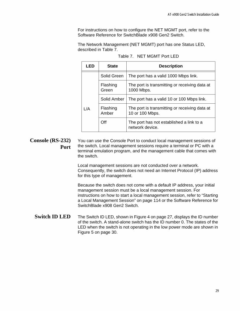
For instructions on how to configure the NET MGMT port, refer to the Software Reference for SwitchBlade x908 Gen2 Switch.
The Network Management (NET MGMT) port has one Status LED, described in Table 7.
Console (RS-232)Port
You can use the Console Port to conduct local management sessions of the switch. Local management sessions require a terminal or PC with a terminal emulation program, and the management cable that comes with the switch.
Local management sessions are not conducted over a network. Consequently, the switch does not need an Internet Protocol (IP) address for this type of management.
Because the switch does not come with a default IP address, your initial management session must be a local management session. For instructions on how to start a local management session, refer to “Starting a Local Management Session” on page 114 or the Software Reference for SwitchBlade x908 Gen2 Switch.
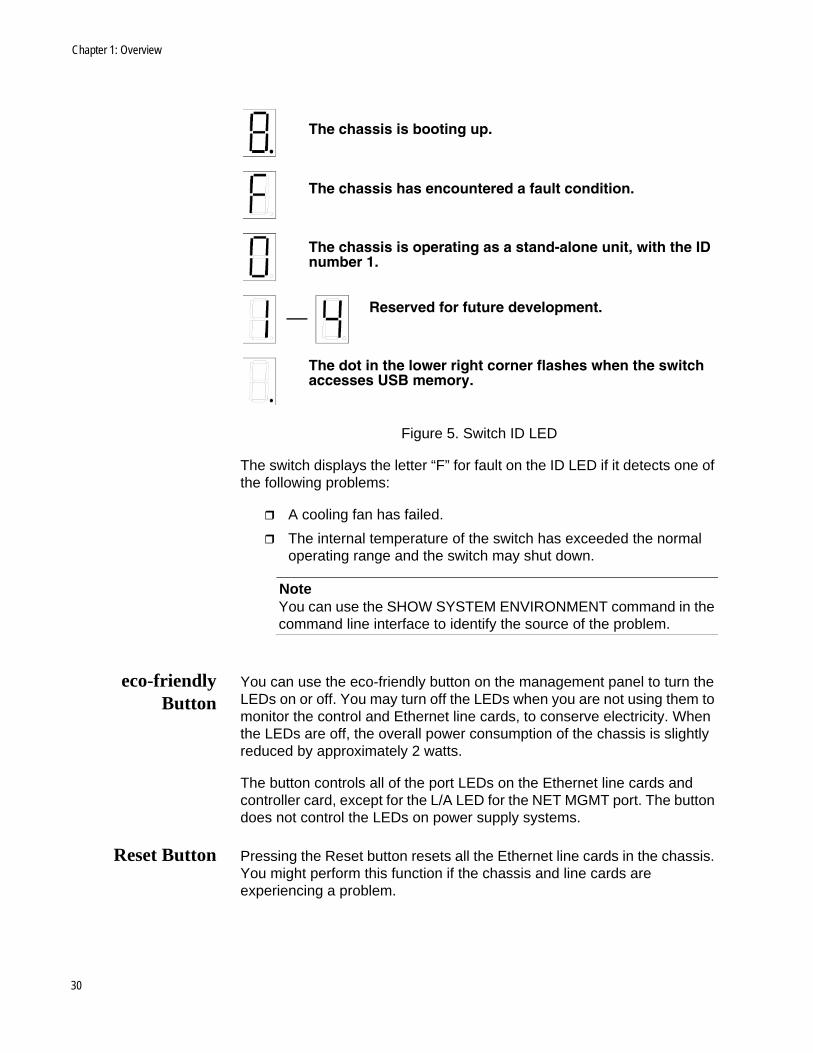
Switch ID LED The Switch ID LED, shown in Figure 4 on page 27, displays the ID number of the switch. A stand-alone switch has the ID number 0. The states of the LED when the switch is not operating in the low power mode are shown in Figure 5 on page 30.
Table 7. NET MGMT Port LED
LED State Description
L/A
Solid Green The port has a valid 1000 Mbps link.
Flashing Green
The port is transmitting or receiving data at 1000 Mbps.
Solid Amber The port has a valid 10 or 100 Mbps link.
Flashing Amber
The port is transmitting or receiving data at 10 or 100 Mbps.
Off The port has not established a link to a network device.
29
Chapter 1: Overview
Figure 5. Switch ID LED
The switch displays the letter “F” for fault on the ID LED if it detects one of the following problems:
A cooling fan has failed.
The internal temperature of the switch has exceeded the normal operating range and the switch may shut down.
NoteYou can use the SHOW SYSTEM ENVIRONMENT command in the command line interface to identify the source of the problem.
eco-friendlyButton
You can use the eco-friendly button on the management panel to turn the LEDs on or off. You may turn off the LEDs when you are not using them to monitor the control and Ethernet line cards, to conserve electricity. When the LEDs are off, the overall power consumption of the chassis is slightly reduced by approximately 2 watts.
The button controls all of the port LEDs on the Ethernet line cards and controller card, except for the L/A LED for the NET MGMT port. The button does not control the LEDs on power supply systems.
Reset Button Pressing the Reset button resets all the Ethernet line cards in the chassis. You might perform this function if the chassis and line cards are experiencing a problem.
The chassis is booting up.
The chassis has encountered a fault condition.
The chassis is operating as a stand-alone unit, with the IDnumber 1.
Reserved for future development.
The dot in the lower right corner flashes when the switchaccesses USB memory.
30
AT-x908 Gen2 Switch Installation Guide
CautionThe Ethernet line cards do not forward network traffic for about three minutes while they initialize the AlliedWare Plus Operating System and configure their parameter settings. Some network traffic may be lost.
NoteTo reset individual line cards in the chassis, use the REBOOT or RELOAD command in the AlliedWare Plus operating system.
31
Chapter 1: Overview
Power Supplies
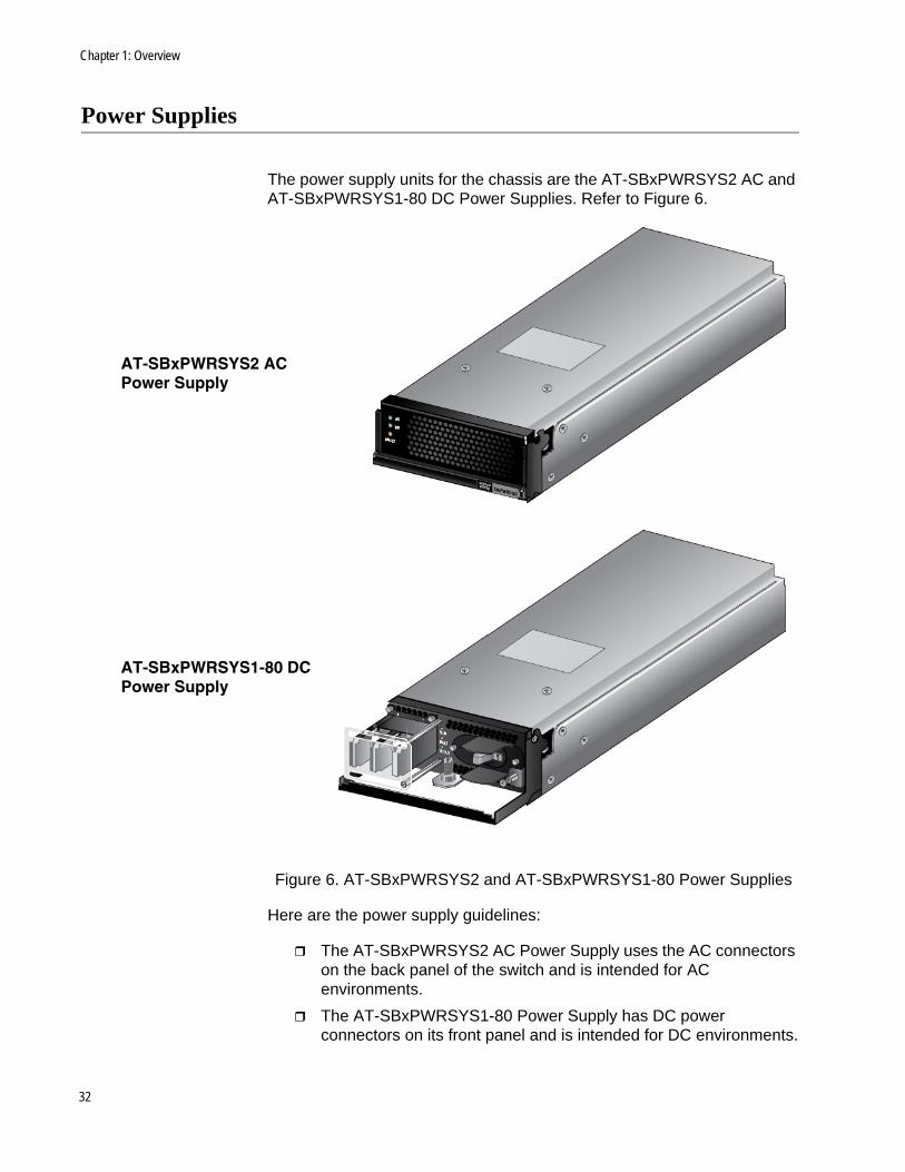
The power supply units for the chassis are the AT-SBxPWRSYS2 AC and AT-SBxPWRSYS1-80 DC Power Supplies. Refer to Figure 6.
Figure 6. AT-SBxPWRSYS2 and AT-SBxPWRSYS1-80 Power Supplies
Here are the power supply guidelines:
The AT-SBxPWRSYS2 AC Power Supply uses the AC connectors on the back panel of the switch and is intended for AC environments.
The AT-SBxPWRSYS1-80 Power Supply has DC power connectors on its front panel and is intended for DC environments.
AT-SBxPWRSYS2 AC Power Supply
AT-SBxPWRSYS1-80 DC Power Supply
32
AT-x908 Gen2 Switch Installation Guide
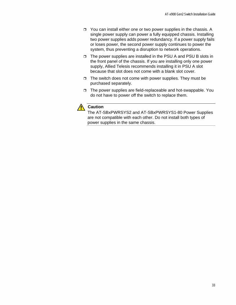
You can install either one or two power supplies in the chassis. A single power supply can power a fully equipped chassis. Installing two power supplies adds power redundancy. If a power supply fails or loses power, the second power supply continues to power the system, thus preventing a disruption to network operations.
The power supplies are installed in the PSU A and PSU B slots in the front panel of the chassis. If you are installing only one power supply, Allied Telesis recommends installing it in PSU A slot because that slot does not come with a blank slot cover.
The switch does not come with power supplies. They must be purchased separately.
The power supplies are field-replaceable and hot-swappable. You do not have to power off the switch to replace them.
CautionThe AT-SBxPWRSYS2 and AT-SBxPWRSYS1-80 Power Supplies are not compatible with each other. Do not install both types of power supplies in the same chassis.
33
Chapter 1: Overview
AT-FAN08 Units
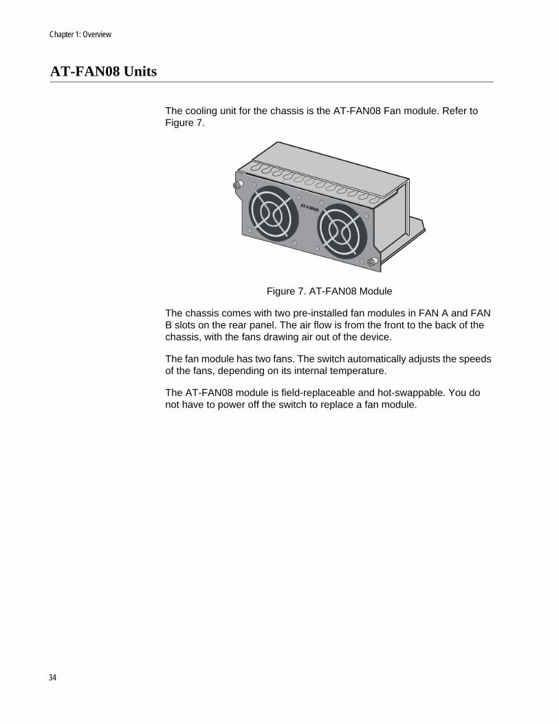
The cooling unit for the chassis is the AT-FAN08 Fan module. Refer to Figure 7.
Figure 7. AT-FAN08 Module
The chassis comes with two pre-installed fan modules in FAN A and FAN B slots on the rear panel. The air flow is from the front to the back of the chassis, with the fans drawing air out of the device.
The fan module has two fans. The switch automatically adjusts the speeds of the fans, depending on its internal temperature.
The AT-FAN08 module is field-replaceable and hot-swappable. You do not have to power off the switch to replace a fan module.
34
AT-x908 Gen2 Switch Installation Guide
Specifying Ports in the Command Line Interface
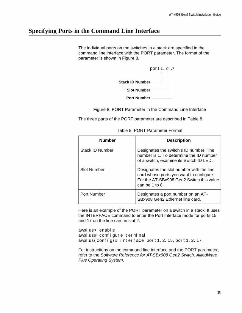
The individual ports on the switches in a stack are specified in the command line interface with the PORT parameter. The format of the parameter is shown in Figure 8.
Figure 8. PORT Parameter in the Command Line Interface
The three parts of the PORT parameter are described in Table 8.
Here is an example of the PORT parameter on a switch in a stack. It uses the INTERFACE command to enter the Port Interface mode for ports 15 and 17 on the line card in slot 2:
awplus> enableawplus# configure terminalawplus(config)# interface port1.2.15,port1.2.17
For instructions on the command line interface and the PORT parameter, refer to the Software Reference for AT-SBx908 Gen2 Switch, AlliedWare Plus Operating System.
Table 8. PORT Parameter Format
Number Description
Stack ID Number Designates the switch’s ID number. The number is 1. To determine the ID number of a switch, examine its Switch ID LED.
Slot Number Designates the slot number with the line card whose ports you want to configure. For the AT-SBx908 Gen2 Switch this value can be 1 to 8.
Port Number Designates a port number on an AT-SBx908 Gen2 Ethernet line card.
port1.n.n
Slot Number
Port Number
Stack ID Number
35

Chapter 1: Overview
36
Chapter 2
Beginning the Installation
The chapter contains the following sections:
“Reviewing Safety Precautions” on page 38
“Choosing a Site for the Chassis” on page 43
“Unpacking the Chassis” on page 44
“Unpacking AT-SBxPWRSYS2 AC Power Supplies” on page 49
“Unpacking AT-SBxPWRSYS1-80 DC Power Supplies” on page 50
37
Chapter 2: Beginning the Installation
Reviewing Safety Precautions
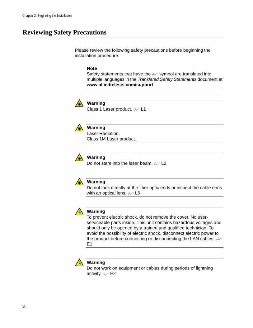
Please review the following safety precautions before beginning the installation procedure.
NoteSafety statements that have the symbol are translated into multiple languages in the Translated Safety Statements document at www.alliedtelesis.com/support.
WarningClass 1 Laser product. L1
WarningLaser Radiation.Class 1M Laser product.
WarningDo not stare into the laser beam. L2
WarningDo not look directly at the fiber optic ends or inspect the cable ends with an optical lens. L6
WarningTo prevent electric shock, do not remove the cover. No user-serviceable parts inside. This unit contains hazardous voltages and should only be opened by a trained and qualified technician. To avoid the possibility of electric shock, disconnect electric power to the product before connecting or disconnecting the LAN cables. E1
WarningDo not work on equipment or cables during periods of lightning activity. E2
38
AT-SBx908 Gen2 Switch Installation Guide
WarningPower cord is used as a disconnection device. To de-energize equipment, disconnect the power cord. E3
WarningClass I Equipment. This equipment must be earthed. The power plug must be connected to a properly wired earth ground socket outlet. An improperly wired socket outlet could place hazardous voltages on accessible metal parts. E4
NotePluggable Equipment. The socket outlet shall be installed near the equipment and shall be easily accessible. E5
CautionAir vents must not be blocked and must have free access to the room ambient air for cooling. E6
WarningOperating Temperatures. This product is designed for a maximum ambient temperature of 50° degrees C. E52
NoteAll Countries: Install product in accordance with local and National Electrical Codes. E8
WarningWhen installing this equipment, always ensure that the frame ground connection is installed first and disconnected last. E11
WarningOnly trained and qualified personnel are allowed to install or replace this equipment. E14
39
Chapter 2: Beginning the Installation
CautionCircuit Overloading: Consideration should be given to the connection of the equipment to the supply circuit and the effect that overloading of circuits might have on overcurrent protection and supply wiring. Appropriate consideration of equipment nameplate ratings should be used when addressing this concern. E21
CautionRisk of explosion if battery is replaced by an incorrect type. Replace only with the same or equivalent type recommended by the manufacturer. Dispose of used batteries according to the manufacturer’s instructions.
Attention: Le remplacement de la batterie par une batterie de type incorrect peut provoquer un danger d’explosion. La remplacer uniquement par une batterie du même type ou de type équivalent recommandée par le constructeur. Les batteries doivent être éliminées conformément aux instructions du constructeur. E22
WarningMounting of the equipment in the rack should be such that a hazardous condition is not created due to uneven mechanical loading. E25
WarningThe chassis may be heavy and awkward to lift. Allied Telesis recommends that you get assistance when mounting the chassis in an equipment rack. E28
NoteUse dedicated power circuits or power conditioners to supply reliable electrical power to the device. E27
WarningThis unit might have more than one power cord. To reduce the risk of electric shock, disconnect all power cords before servicing the unit. E30
40
AT-SBx908 Gen2 Switch Installation Guide
NoteIf installed in a closed or multi-unit rack assembly, the operating ambient temperature of the rack environment may be greater than the room ambient temperature. Therefore, consideration should be given to installing the equipment in an environment compatible with the manufacturer’s maximum rated ambient temperature (Tmra). E35
CautionInstallation of the equipment in a rack should be such that the amount of air flow required for safe operation of the equipment is not compromised. E36
WarningReliable earthing of rack-mounted equipment should be maintained. Particular attention should be given to supply connections other than direct connections to the branch circuits (e.g., use of power strips). E37
WarningThis product may have multiple AC power cords installed. To de-energize this equipment, disconnect all power cords from the device. E41
CautionAn Energy Hazard exists inside this equipment. Do not insert hands or tools into open chassis slots or plugs. E44
WarningThis equipment shall be installed in a Restricted Access location. E45
CautionThe unit does not contain serviceable components. Please return damaged units for servicing. E42
41
Chapter 2: Beginning the Installation
WarningThe temperature of an operational SFP or SFP+ transceiver may exceed 70° C (158° F). Exercise caution when removing or handling transceivers with unprotected hands. E43
WarningThe grounding lug on the rear panel of the chassis is for supplemental grounding. The chassis must be supplied by a grounded three wire AC source through the power supply cord.
42
AT-SBx908 Gen2 Switch Installation Guide
Choosing a Site for the Chassis
Observe these requirements when planning the installation of the chassis.
The AT-SBx908 Gen2 Chassis should be installed in a standard 19-inch equipment rack. It should not be installed on a table, desk, or wall.
Check that the equipment rack is safely secured so that it will not tip over. Devices should be installed in the rack starting at the bottom, with the heavier devices near the bottom of the rack.
The power outlet should be located near the chassis and be easily accessible.
The site should allow for easy access to the ports on the front of the switch, so that you can easily connect and disconnect cables, and view the port LEDs.
The site should allow for adequate air flow around the unit and through the cooling vents on the front and rear panels. (The ventilation direction is from front to back, with the fans on the back panel drawing the air out of the unit.)
The site should not expose the chassis to moisture or water.
The site should be a dust-free environment.
The site should include dedicated power circuits or power conditioners to supply reliable electrical power to the network devices.
Twisted pair cabling should not be exposed to sources of electrical noise, such as radio transmitters, broadband amplifiers, power lines, electric motors, or fluorescent fixtures.
Switch ports are suitable for intra-building connections, or where non-exposed cabling is required.
Do not install the chassis in a wiring or utility box because it might overheat and fail from inadequate airflow.
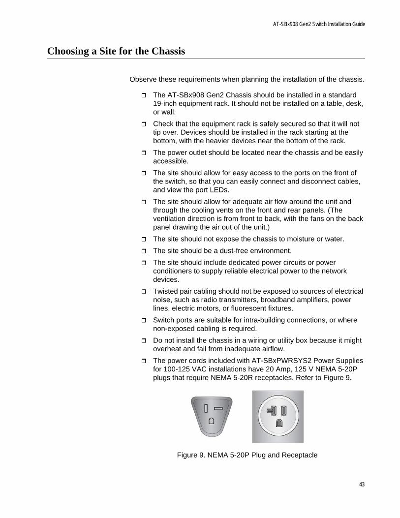
The power cords included with AT-SBxPWRSYS2 Power Supplies for 100-125 VAC installations have 20 Amp, 125 V NEMA 5-20P plugs that require NEMA 5-20R receptacles. Refer to Figure 9.
Figure 9. NEMA 5-20P Plug and Receptacle
43
Chapter 2: Beginning the Installation
Unpacking the Chassis
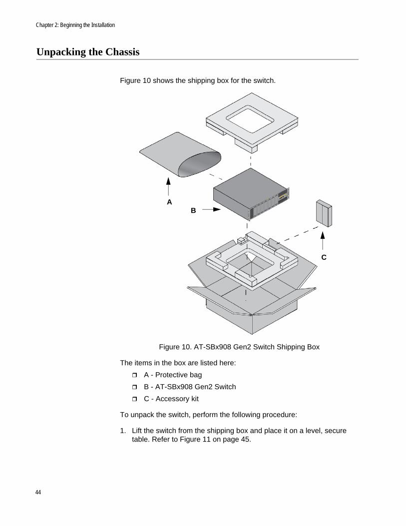
Figure 10 shows the shipping box for the switch.
Figure 10. AT-SBx908 Gen2 Switch Shipping Box
The items in the box are listed here:
A - Protective bag
B - AT-SBx908 Gen2 Switch
C - Accessory kit
To unpack the switch, perform the following procedure:
1. Lift the switch from the shipping box and place it on a level, secure table. Refer to Figure 11 on page 45.
AB
C
44
AT-SBx908 Gen2 Switch Installation Guide
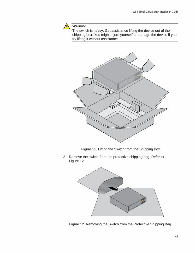
WarningThe switch is heavy. Get assistance lifting the device out of the shipping box. You might injure yourself or damage the device if you try lifting it without assistance.
Figure 11. Lifting the Switch from the Shipping Box
2. Remove the switch from the protective shipping bag. Refer to Figure 12.
Figure 12. Removing the Switch from the Protective Shipping Bag.
45
Chapter 2: Beginning the Installation
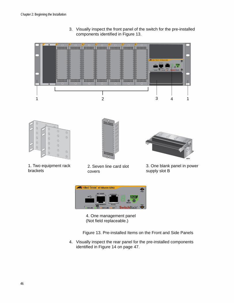
3. Visually inspect the front panel of the switch for the pre-installed components identified in Figure 13.
Figure 13. Pre-installed Items on the Front and Side Panels
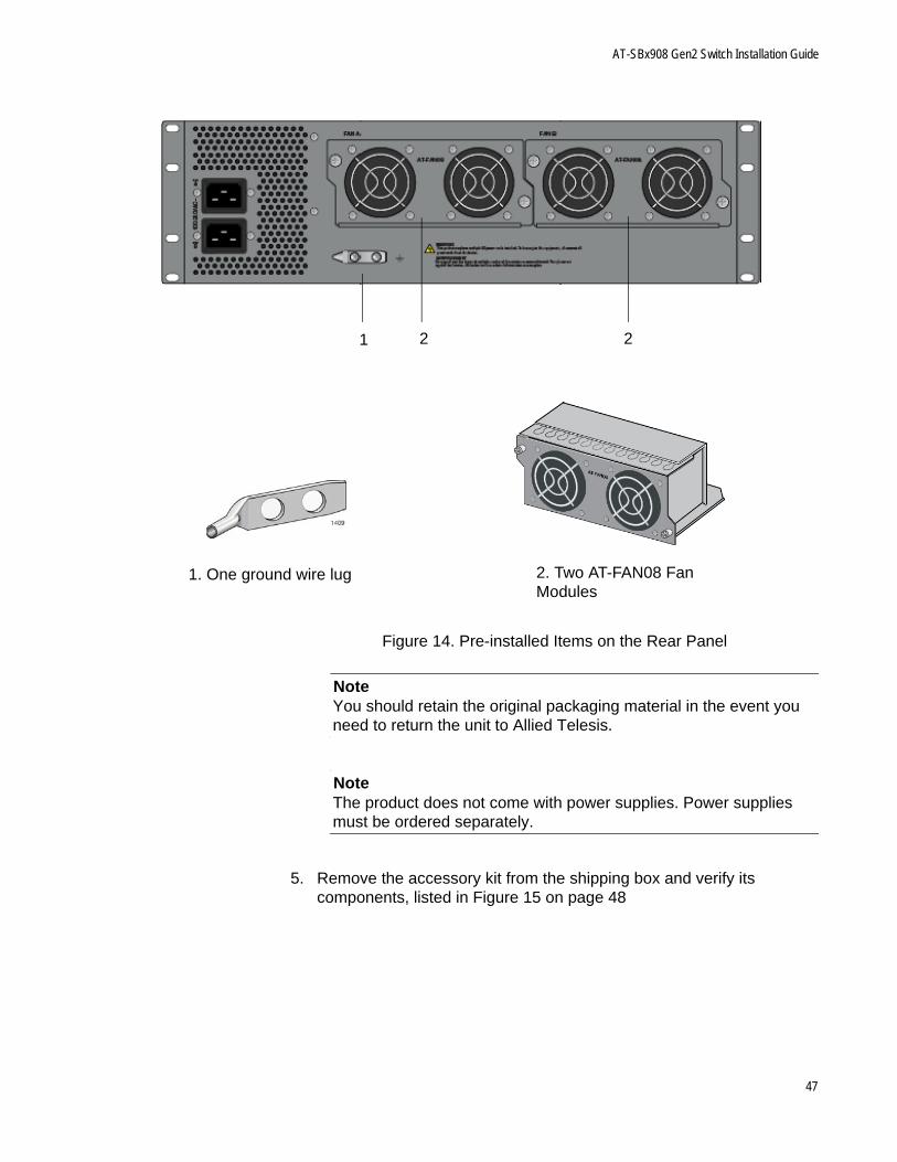
4. Visually inspect the rear panel for the pre-installed components identified in Figure 14 on page 47.
2. Seven line card slot covers
1. Two equipment rack brackets
3. One blank panel in power supply slot B
1 12 3 4
4. One management panel (Not field replaceable.)
46
AT-SBx908 Gen2 Switch Installation Guide
Figure 14. Pre-installed Items on the Rear Panel
NoteYou should retain the original packaging material in the event you need to return the unit to Allied Telesis.
NoteThe product does not come with power supplies. Power supplies must be ordered separately.
5. Remove the accessory kit from the shipping box and verify its components, listed in Figure 15 on page 48
2. Two AT-FAN08 Fan Modules
1. One ground wire lug
21 2
47
Chapter 2: Beginning the Installation
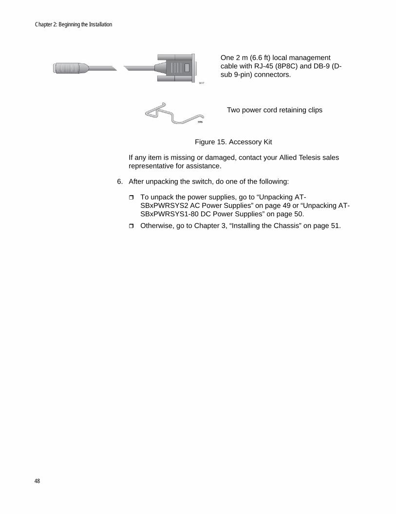
Figure 15. Accessory Kit
If any item is missing or damaged, contact your Allied Telesis sales representative for assistance.
6. After unpacking the switch, do one of the following:
To unpack the power supplies, go to “Unpacking AT-SBxPWRSYS2 AC Power Supplies” on page 49 or “Unpacking AT-SBxPWRSYS1-80 DC Power Supplies” on page 50.
Otherwise, go to Chapter 3, “Installing the Chassis” on page 51.
One 2 m (6.6 ft) local management cable with RJ-45 (8P8C) and DB-9 (D-sub 9-pin) connectors.
Two power cord retaining clips
48
AT-SBx908 Gen2 Switch Installation Guide
Unpacking AT-SBxPWRSYS2 AC Power Supplies
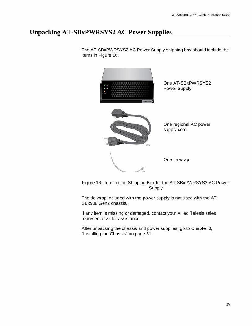
The AT-SBxPWRSYS2 AC Power Supply shipping box should include the items in Figure 16.
Figure 16. Items in the Shipping Box for the AT-SBxPWRSYS2 AC Power Supply
The tie wrap included with the power supply is not used with the AT-SBx908 Gen2 chassis.
If any item is missing or damaged, contact your Allied Telesis sales representative for assistance.
After unpacking the chassis and power supplies, go to Chapter 3, “Installing the Chassis” on page 51.
One AT-SBxPWRSYS2 Power Supply
One regional AC power supply cord
One tie wrap
49
Chapter 2: Beginning the Installation
Unpacking AT-SBxPWRSYS1-80 DC Power Supplies
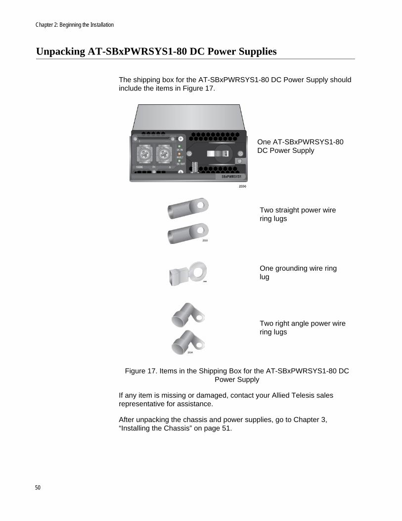
The shipping box for the AT-SBxPWRSYS1-80 DC Power Supply should include the items in Figure 17.
Figure 17. Items in the Shipping Box for the AT-SBxPWRSYS1-80 DC Power Supply
If any item is missing or damaged, contact your Allied Telesis sales representative for assistance.
After unpacking the chassis and power supplies, go to Chapter 3, “Installing the Chassis” on page 51.
One AT-SBxPWRSYS1-80 DC Power Supply
Two straight power wire ring lugs
Two right angle power wire ring lugs
One grounding wire ring lug
50

Chapter 3
Installing the Chassis
The procedures in this chapter explain how to install the chassis in a standard 19-inch equipment rack. The procedures are listed here:
“Tools and Material” on page 52
“Adjusting the Equipment Rack Brackets” on page 53
“Installing the Chassis in an Equipment Rack” on page 57
“Installing the Chassis Grounding Wire” on page 58
“Installing AT-SBxPWRSYS2 AC Power Supplies” on page 61
“Installing AT-SBxPWRSYS1-80 DC Power Supplies” on page 65
“Installing Ethernet Line Cards” on page 69
“Installing Blank Line Card Slot Covers” on page 73
“Installing the Blank Power Supply Slot Cover” on page 75
“Installing the Power Cord Retaining Clips” on page 77
51

Chapter 3: Installing the Chassis
Tools and Material
You need to provide the following tools and material to install the chassis:
#2 Phillips-head screwdriver
Eight screws for a standard 19-inch equipment rack
10 AWG stranded grounding wire
Wire insulation stripper
Crimping tool
52
AT-SBx908 Gen2 Switch Installation Guide
Adjusting the Equipment Rack Brackets
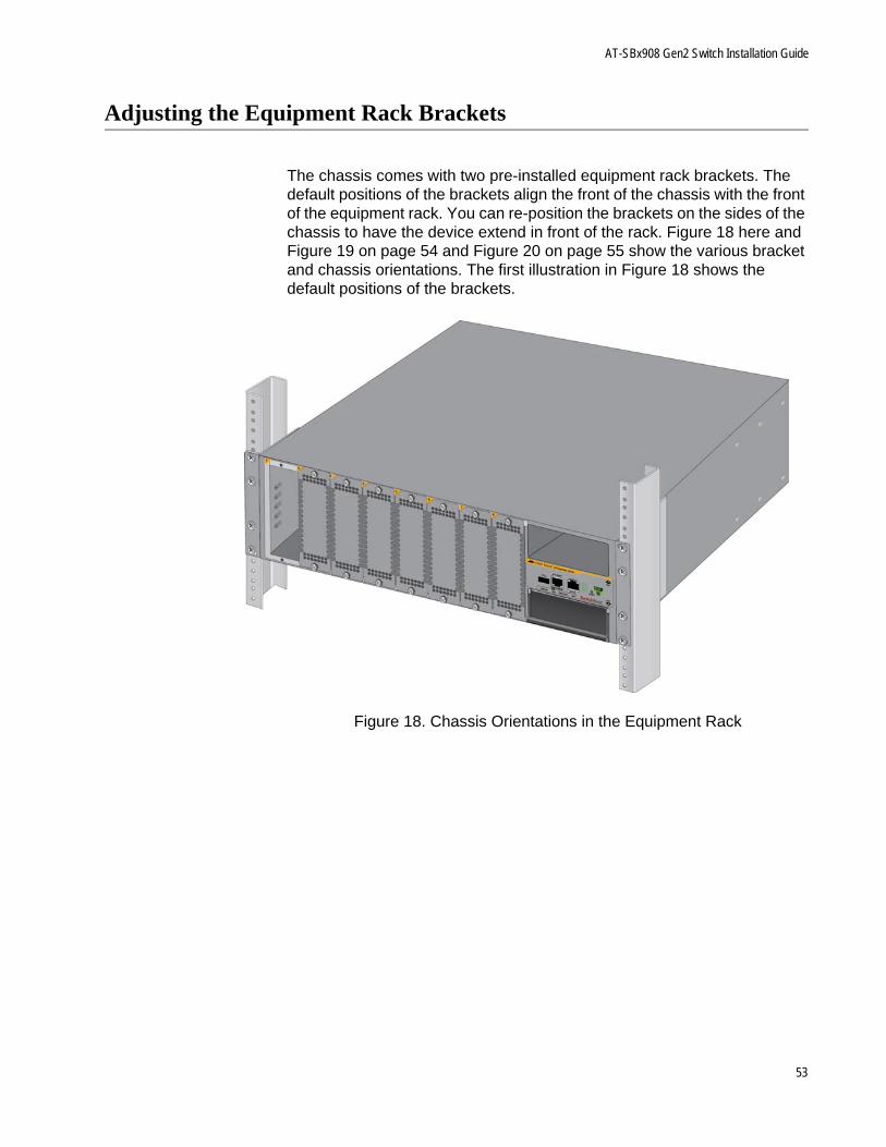
The chassis comes with two pre-installed equipment rack brackets. The default positions of the brackets align the front of the chassis with the front of the equipment rack. You can re-position the brackets on the sides of the chassis to have the device extend in front of the rack. Figure 18 here and Figure 19 on page 54 and Figure 20 on page 55 show the various bracket and chassis orientations. The first illustration in Figure 18 shows the default positions of the brackets.
Figure 18. Chassis Orientations in the Equipment Rack
53
Chapter 3: Installing the Chassis
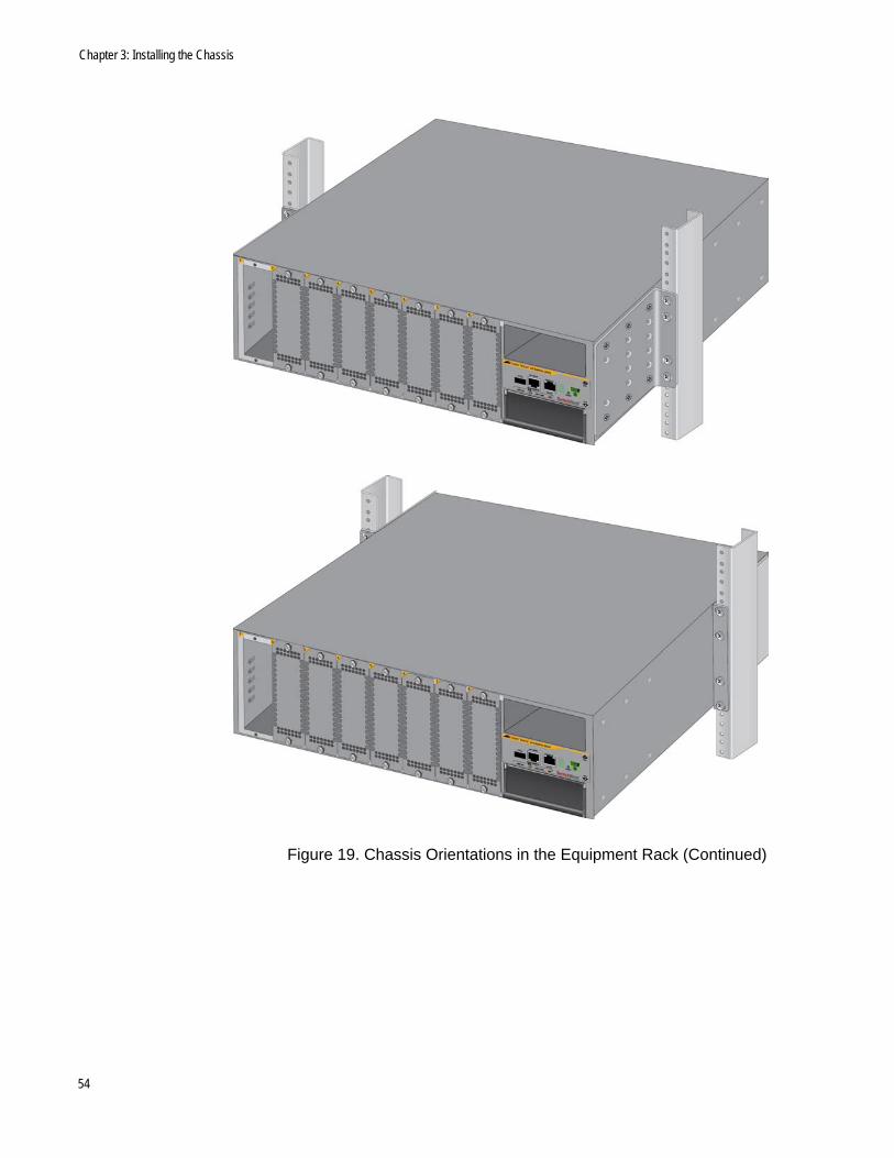
Figure 19. Chassis Orientations in the Equipment Rack (Continued)
54
AT-SBx908 Gen2 Switch Installation Guide
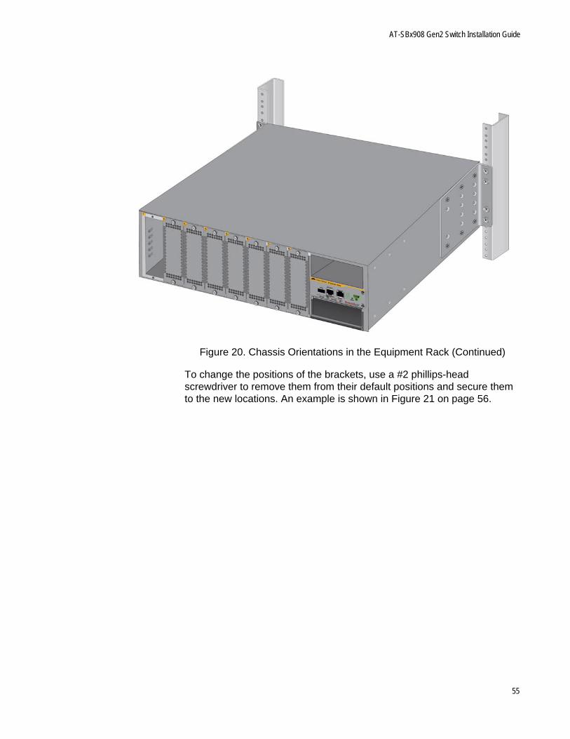
Figure 20. Chassis Orientations in the Equipment Rack (Continued)
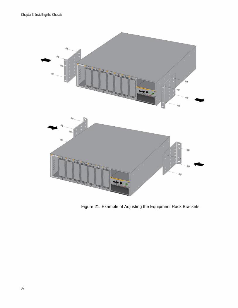
To change the positions of the brackets, use a #2 phillips-head screwdriver to remove them from their default positions and secure them to the new locations. An example is shown in Figure 21 on page 56.
55
Chapter 3: Installing the Chassis
Figure 21. Example of Adjusting the Equipment Rack Brackets
56
AT-SBx908 Gen2 Switch Installation Guide
Installing the Chassis in an Equipment Rack
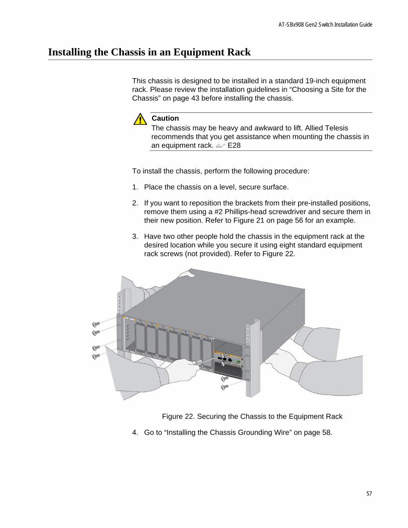
This chassis is designed to be installed in a standard 19-inch equipment rack. Please review the installation guidelines in “Choosing a Site for the Chassis” on page 43 before installing the chassis.
CautionThe chassis may be heavy and awkward to lift. Allied Telesis recommends that you get assistance when mounting the chassis in an equipment rack. E28
To install the chassis, perform the following procedure:
1. Place the chassis on a level, secure surface.
2. If you want to reposition the brackets from their pre-installed positions, remove them using a #2 Phillips-head screwdriver and secure them in their new position. Refer to Figure 21 on page 56 for an example.
3. Have two other people hold the chassis in the equipment rack at the desired location while you secure it using eight standard equipment rack screws (not provided). Refer to Figure 22.
Figure 22. Securing the Chassis to the Equipment Rack
4. Go to “Installing the Chassis Grounding Wire” on page 58.
57

Chapter 3: Installing the Chassis
Installing the Chassis Grounding Wire
This procedure explains how to connect a grounding wire to the chassis. The chassis requires a permanent connection for the line cards and power supplies to a good earth ground. The procedure requires the following items:
Grounding lug (pre-installed on the rear panel of the chassis)
#2 Phillips-head screwdriver (not provided)
Crimping tool (not provided)
10 AWG stranded grounding wire (not provided)
To connect the chassis to an earth ground, perform the following procedure:
1. Prepare an adequate length of stranded grounding wire (10 AWG) for the ground connection by stripping it as shown in Figure 23.
Figure 23. Stripping the Grounding Wire
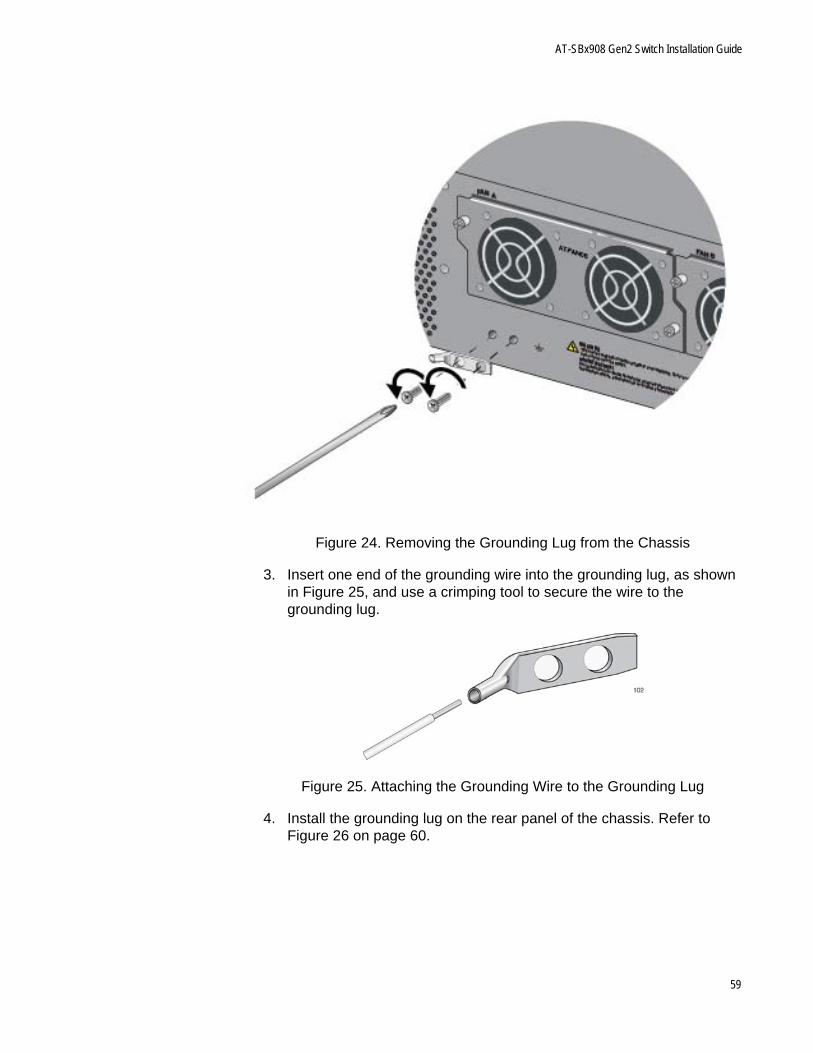
2. Use a #2 Phillips-head screwdriver to remove the two screws that secure the grounding lug to the rear panel of the chassis. Refer to Figure 24 on page 59.
58
AT-SBx908 Gen2 Switch Installation Guide
Figure 24. Removing the Grounding Lug from the Chassis
3. Insert one end of the grounding wire into the grounding lug, as shown in Figure 25, and use a crimping tool to secure the wire to the grounding lug.
Figure 25. Attaching the Grounding Wire to the Grounding Lug
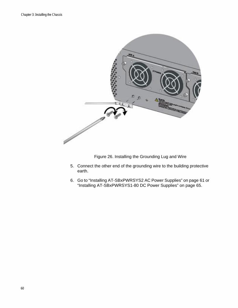
4. Install the grounding lug on the rear panel of the chassis. Refer to Figure 26 on page 60.
59
Chapter 3: Installing the Chassis
Figure 26. Installing the Grounding Lug and Wire
5. Connect the other end of the grounding wire to the building protective earth.
6. Go to “Installing AT-SBxPWRSYS2 AC Power Supplies” on page 61 or “Installing AT-SBxPWRSYS1-80 DC Power Supplies” on page 65.
60
AT-SBx908 Gen2 Switch Installation Guide
Installing AT-SBxPWRSYS2 AC Power Supplies
This section contains the procedure for installing AT-SBxPWRSYS2 AC Power Supplies in the chassis. For a list of the components that come with the power supply, refer to “Unpacking AT-SBxPWRSYS2 AC Power Supplies” on page 49.
WarningThe power supply is heavy. Use both hands to lift it. You might injure yourself or damage the equipment if you drop it.
CautionThe device can be damaged by static electricity. Be sure to follow proper anti-static precautions when installing the device. Allied Telesis recommends using a properly grounded wrist strap or other personal anti-static device and an anti-static mat.
To install power supplies in the chassis, perform the following procedure:
1. Choose a slot for the power supply. The power supply slots are labeled PSU A and PSU B
If you are installing only one power supply, you may install it in either slot. Allied Telesis recommends PSU A because that slot does not come with a blank power supply panel.
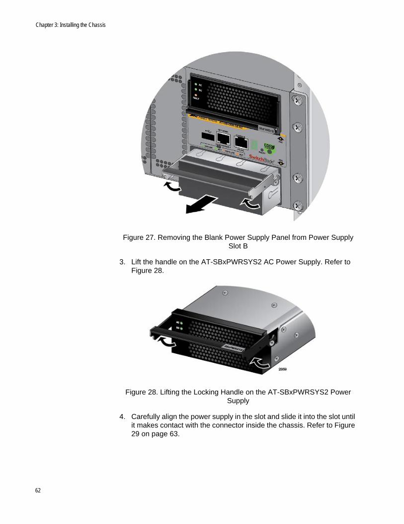
2. If there is already a power supply in PSU A, lift the handle on the blank power supply panel in PSU B and slide the panel from the slot. Refer to Figure 27 on page 62.
61
Chapter 3: Installing the Chassis
Figure 27. Removing the Blank Power Supply Panel from Power Supply Slot B
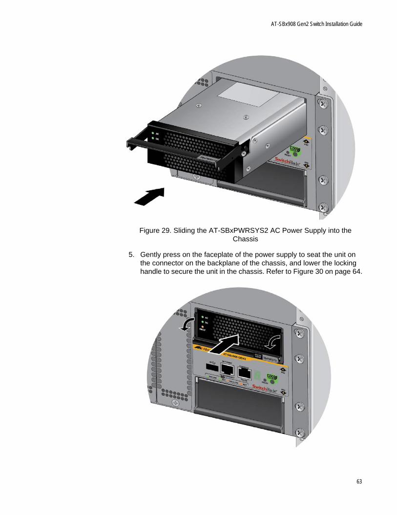
3. Lift the handle on the AT-SBxPWRSYS2 AC Power Supply. Refer to Figure 28.
Figure 28. Lifting the Locking Handle on the AT-SBxPWRSYS2 Power Supply
4. Carefully align the power supply in the slot and slide it into the slot until it makes contact with the connector inside the chassis. Refer to Figure 29 on page 63.
62
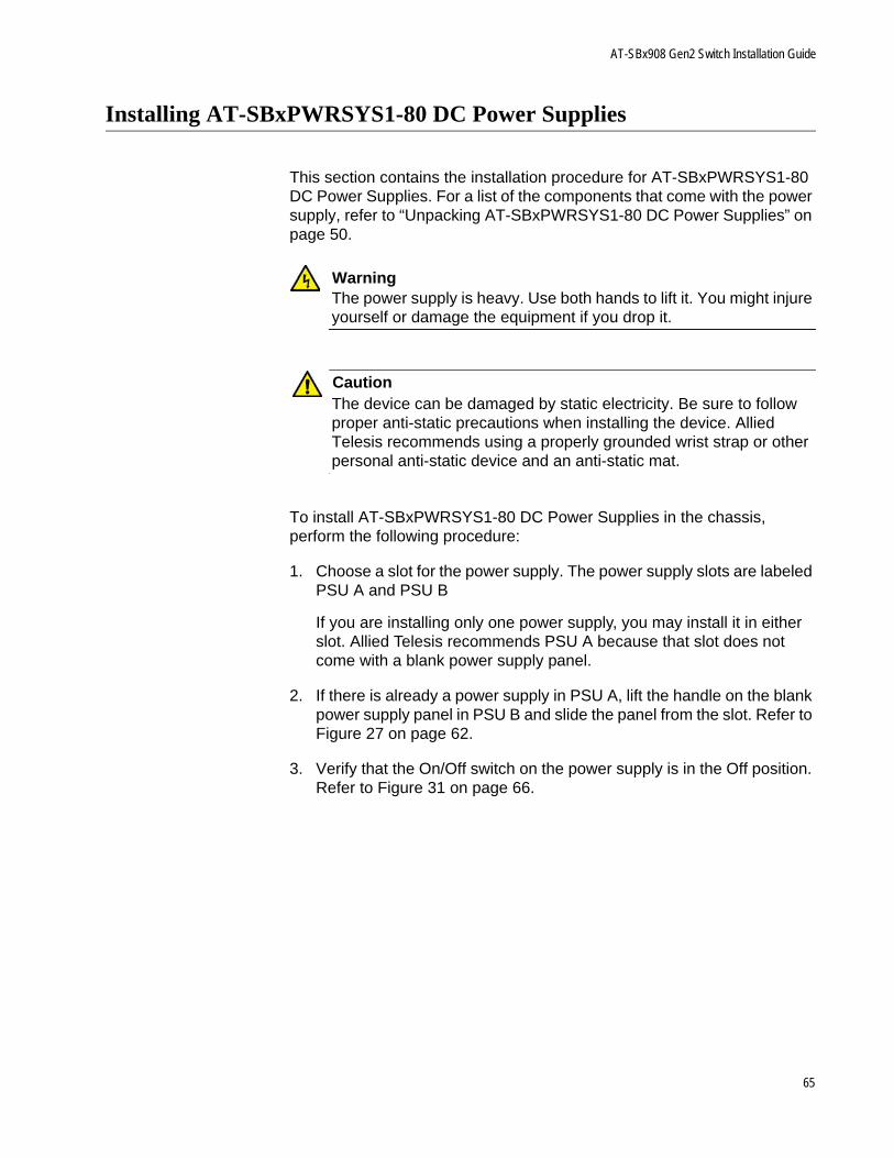
AT-SBx908 Gen2 Switch Installation Guide
Figure 29. Sliding the AT-SBxPWRSYS2 AC Power Supply into the Chassis
5. Gently press on the faceplate of the power supply to seat the unit on the connector on the backplane of the chassis, and lower the locking handle to secure the unit in the chassis. Refer to Figure 30 on page 64.
63

Chapter 3: Installing the Chassis
Figure 30. Lowering the Locking Handle on the AT-SBxPWRSYS2 AC Power Supply
6. Visually inspect the power supply to be sure that its faceplate is flush against the front panel of the chassis and the locking handle is fully down.
7. If necessary, repeat this procedure to install a second power supply.
8. After installing the power supplies, go to “Installing Ethernet Line Cards” on page 69.
64
AT-SBx908 Gen2 Switch Installation Guide
Installing AT-SBxPWRSYS1-80 DC Power Supplies
This section contains the installation procedure for AT-SBxPWRSYS1-80 DC Power Supplies. For a list of the components that come with the power supply, refer to “Unpacking AT-SBxPWRSYS1-80 DC Power Supplies” on page 50.
WarningThe power supply is heavy. Use both hands to lift it. You might injure yourself or damage the equipment if you drop it.
CautionThe device can be damaged by static electricity. Be sure to follow proper anti-static precautions when installing the device. Allied Telesis recommends using a properly grounded wrist strap or other personal anti-static device and an anti-static mat.
To install AT-SBxPWRSYS1-80 DC Power Supplies in the chassis, perform the following procedure:
1. Choose a slot for the power supply. The power supply slots are labeled PSU A and PSU B
If you are installing only one power supply, you may install it in either slot. Allied Telesis recommends PSU A because that slot does not come with a blank power supply panel.
2. If there is already a power supply in PSU A, lift the handle on the blank power supply panel in PSU B and slide the panel from the slot. Refer to Figure 27 on page 62.
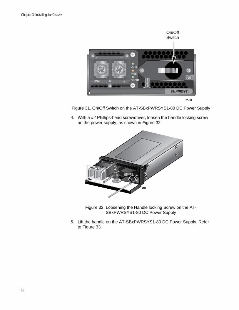
3. Verify that the On/Off switch on the power supply is in the Off position. Refer to Figure 31 on page 66.
65
Chapter 3: Installing the Chassis
Figure 31. On/Off Switch on the AT-SBxPWRSYS1-80 DC Power Supply
4. With a #2 Phillips-head screwdriver, loosen the handle locking screw on the power supply, as shown in Figure 32.
Figure 32. Loosening the Handle locking Screw on the AT-SBxPWRSYS1-80 DC Power Supply
5. Lift the handle on the AT-SBxPWRSYS1-80 DC Power Supply. Refer to Figure 33.
On/Off Switch
66
AT-SBx908 Gen2 Switch Installation Guide
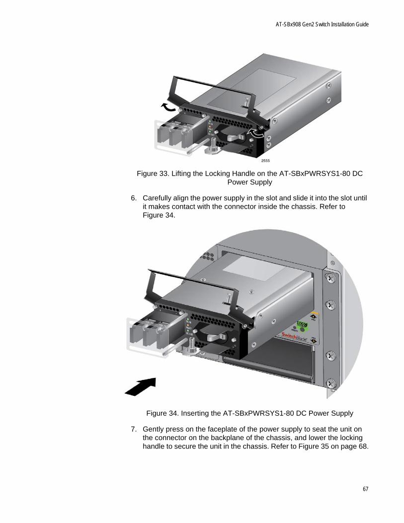
Figure 33. Lifting the Locking Handle on the AT-SBxPWRSYS1-80 DC Power Supply
6. Carefully align the power supply in the slot and slide it into the slot until it makes contact with the connector inside the chassis. Refer to Figure 34.
Figure 34. Inserting the AT-SBxPWRSYS1-80 DC Power Supply
7. Gently press on the faceplate of the power supply to seat the unit on the connector on the backplane of the chassis, and lower the locking handle to secure the unit in the chassis. Refer to Figure 35 on page 68.
67
Chapter 3: Installing the Chassis
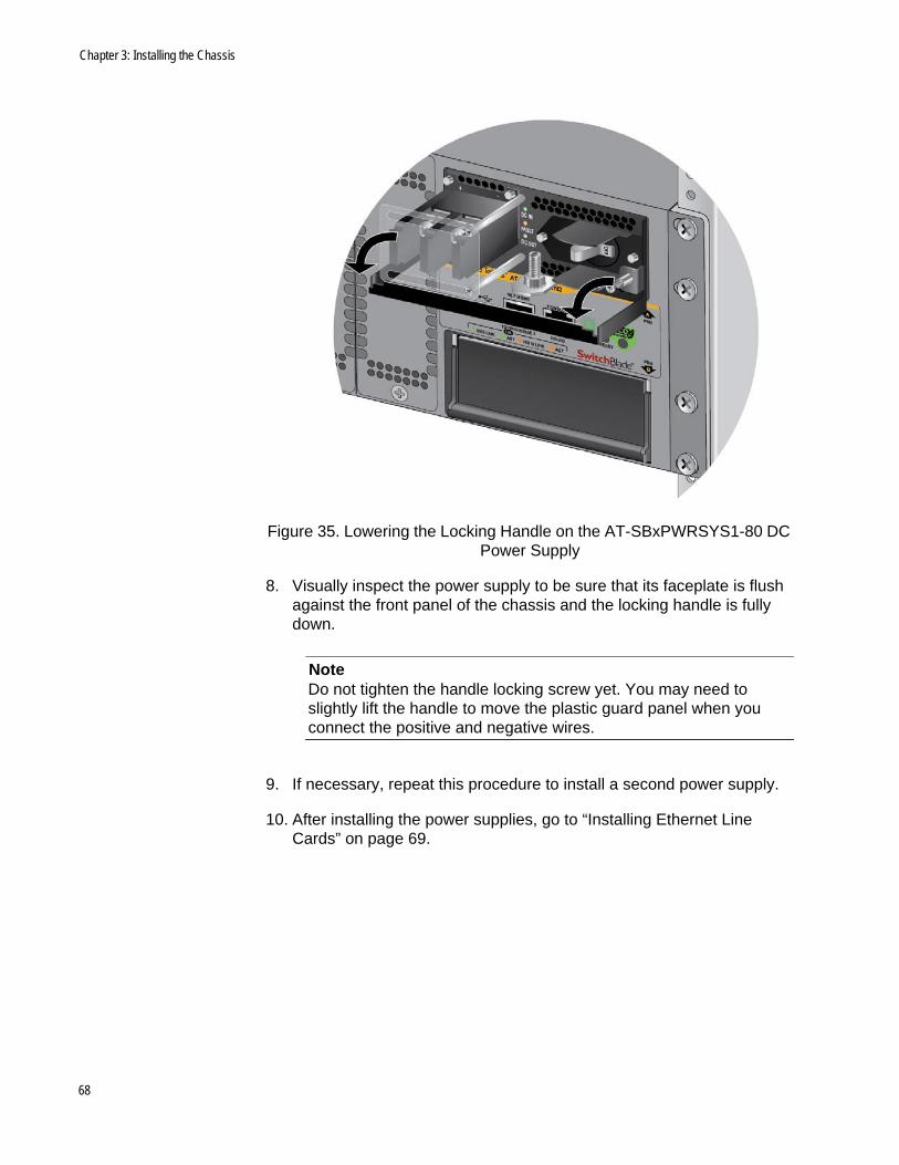
Figure 35. Lowering the Locking Handle on the AT-SBxPWRSYS1-80 DC Power Supply
8. Visually inspect the power supply to be sure that its faceplate is flush against the front panel of the chassis and the locking handle is fully down.
NoteDo not tighten the handle locking screw yet. You may need to slightly lift the handle to move the plastic guard panel when you connect the positive and negative wires.
9. If necessary, repeat this procedure to install a second power supply.
10. After installing the power supplies, go to “Installing Ethernet Line Cards” on page 69.
68
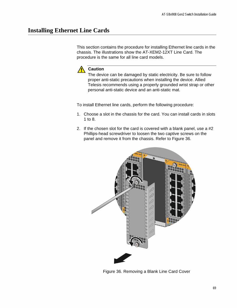
AT-SBx908 Gen2 Switch Installation Guide
Installing Ethernet Line Cards
This section contains the procedure for installing Ethernet line cards in the chassis. The illustrations show the AT-XEM2-12XT Line Card. The procedure is the same for all line card models.
CautionThe device can be damaged by static electricity. Be sure to follow proper anti-static precautions when installing the device. Allied Telesis recommends using a properly grounded wrist strap or other personal anti-static device and an anti-static mat.
To install Ethernet line cards, perform the following procedure:
1. Choose a slot in the chassis for the card. You can install cards in slots 1 to 8.
2. If the chosen slot for the card is covered with a blank panel, use a #2 Phillips-head screwdriver to loosen the two captive screws on the panel and remove it from the chassis. Refer to Figure 36.
Figure 36. Removing a Blank Line Card Cover
69
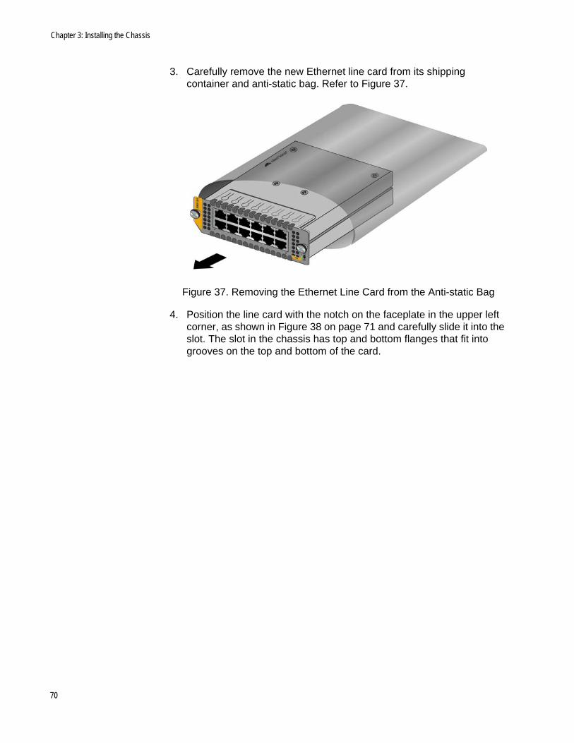
Chapter 3: Installing the Chassis
3. Carefully remove the new Ethernet line card from its shipping container and anti-static bag. Refer to Figure 37.
Figure 37. Removing the Ethernet Line Card from the Anti-static Bag
4. Position the line card with the notch on the faceplate in the upper left corner, as shown in Figure 38 on page 71 and carefully slide it into the slot. The slot in the chassis has top and bottom flanges that fit into grooves on the top and bottom of the card.
70
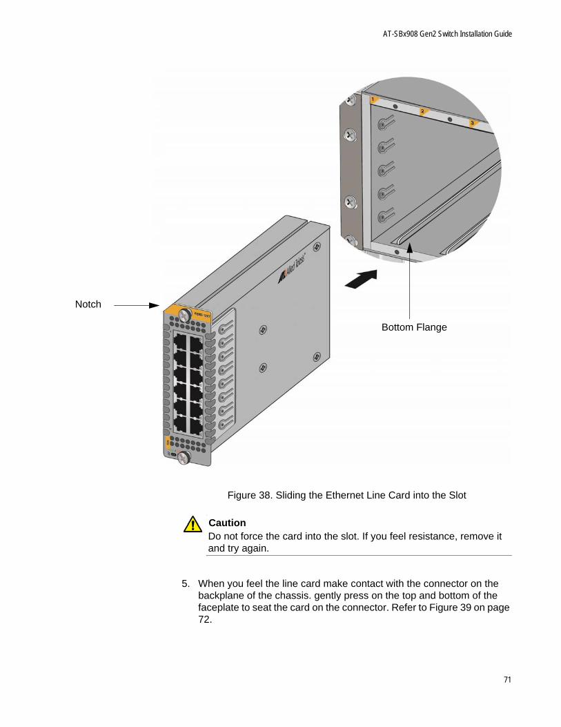
AT-SBx908 Gen2 Switch Installation Guide
Figure 38. Sliding the Ethernet Line Card into the Slot
CautionDo not force the card into the slot. If you feel resistance, remove it and try again.
5. When you feel the line card make contact with the connector on the backplane of the chassis. gently press on the top and bottom of the faceplate to seat the card on the connector. Refer to Figure 39 on page 72.
Bottom Flange
Notch
71
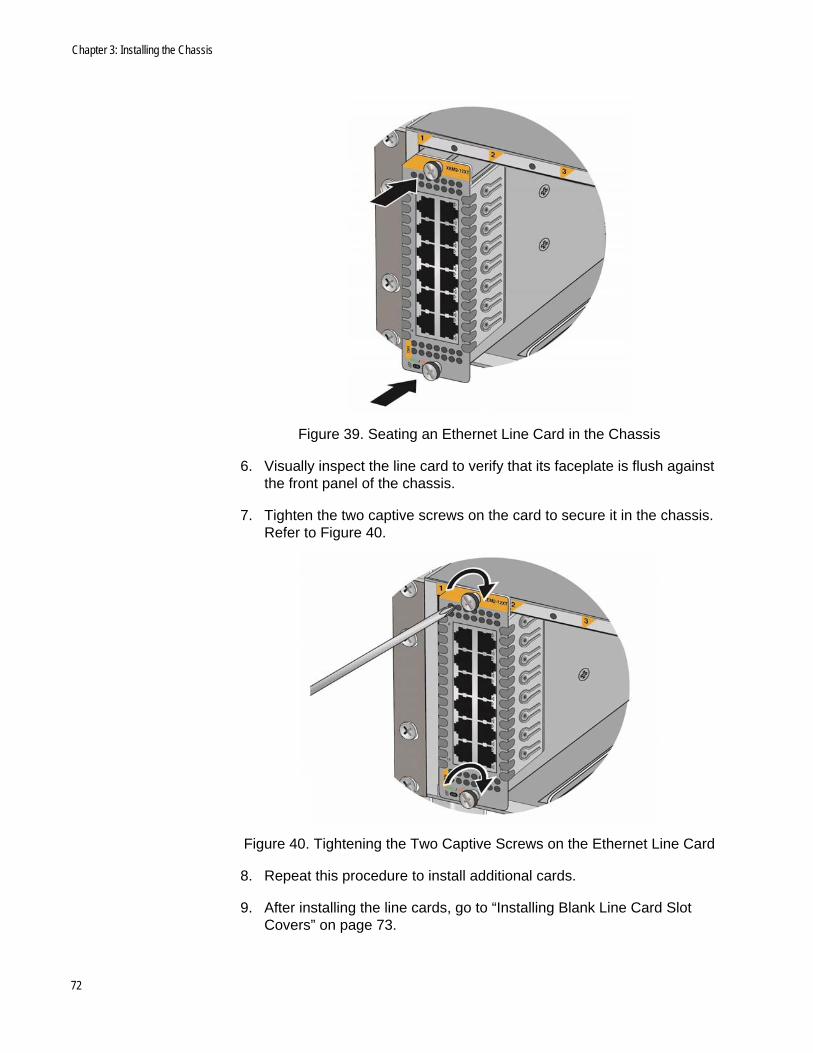
Chapter 3: Installing the Chassis
Figure 39. Seating an Ethernet Line Card in the Chassis
6. Visually inspect the line card to verify that its faceplate is flush against the front panel of the chassis.
7. Tighten the two captive screws on the card to secure it in the chassis. Refer to Figure 40.
Figure 40. Tightening the Two Captive Screws on the Ethernet Line Card
8. Repeat this procedure to install additional cards.
9. After installing the line cards, go to “Installing Blank Line Card Slot Covers” on page 73.
72
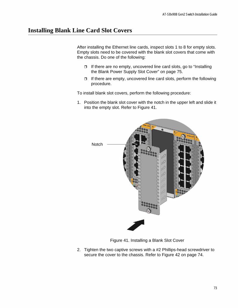
AT-SBx908 Gen2 Switch Installation Guide
Installing Blank Line Card Slot Covers
After installing the Ethernet line cards, inspect slots 1 to 8 for empty slots. Empty slots need to be covered with the blank slot covers that come with the chassis. Do one of the following:
If there are no empty, uncovered line card slots, go to “Installing the Blank Power Supply Slot Cover” on page 75.
If there are empty, uncovered line card slots, perform the following procedure.
To install blank slot covers, perform the following procedure:
1. Position the blank slot cover with the notch in the upper left and slide it into the empty slot. Refer to Figure 41.
Figure 41. Installing a Blank Slot Cover
2. Tighten the two captive screws with a #2 Phillips-head screwdriver to secure the cover to the chassis. Refer to Figure 42 on page 74.
Notch
73
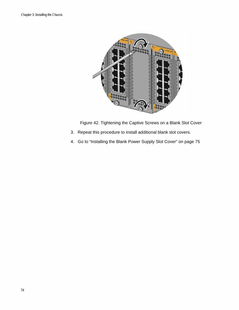
Chapter 3: Installing the Chassis
Figure 42. Tightening the Captive Screws on a Blank Slot Cover
3. Repeat this procedure to install additional blank slot covers.
4. Go to “Installing the Blank Power Supply Slot Cover” on page 75
74
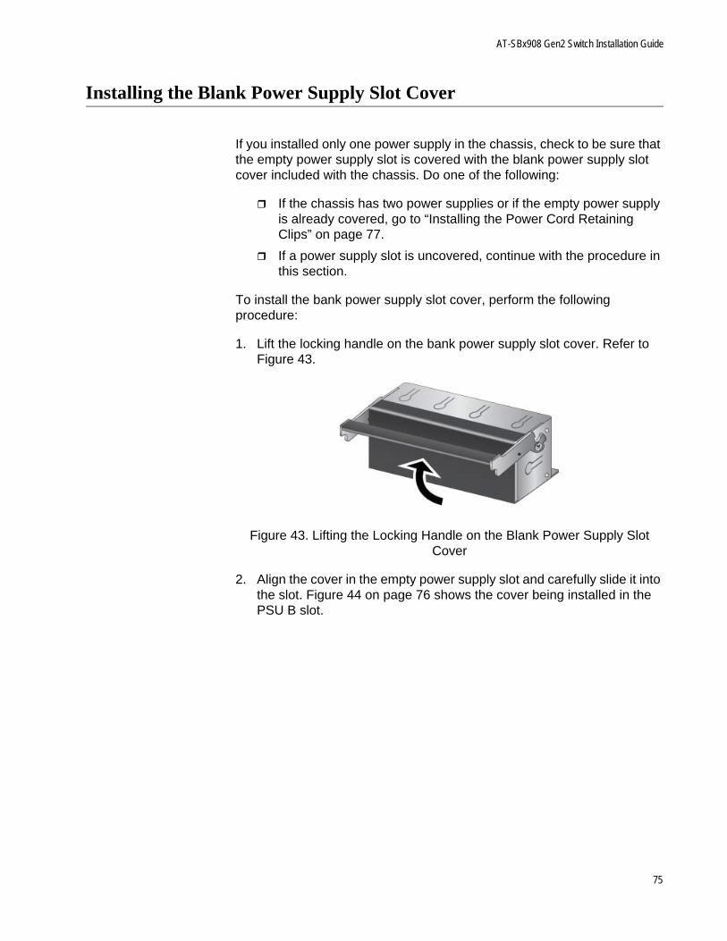
AT-SBx908 Gen2 Switch Installation Guide
Installing the Blank Power Supply Slot Cover
If you installed only one power supply in the chassis, check to be sure that the empty power supply slot is covered with the blank power supply slot cover included with the chassis. Do one of the following:
If the chassis has two power supplies or if the empty power supply is already covered, go to “Installing the Power Cord Retaining Clips” on page 77.
If a power supply slot is uncovered, continue with the procedure in this section.
To install the bank power supply slot cover, perform the following procedure:
1. Lift the locking handle on the bank power supply slot cover. Refer to Figure 43.
Figure 43. Lifting the Locking Handle on the Blank Power Supply Slot Cover
2. Align the cover in the empty power supply slot and carefully slide it into the slot. Figure 44 on page 76 shows the cover being installed in the PSU B slot.
75
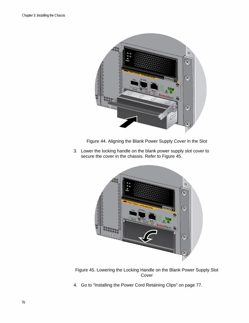
Chapter 3: Installing the Chassis
Figure 44. Aligning the Blank Power Supply Cover in the Slot
3. Lower the locking handle on the blank power supply slot cover to secure the cover in the chassis. Refer to Figure 45.
Figure 45. Lowering the Locking Handle on the Blank Power Supply Slot Cover
4. Go to “Installing the Power Cord Retaining Clips” on page 77.
76
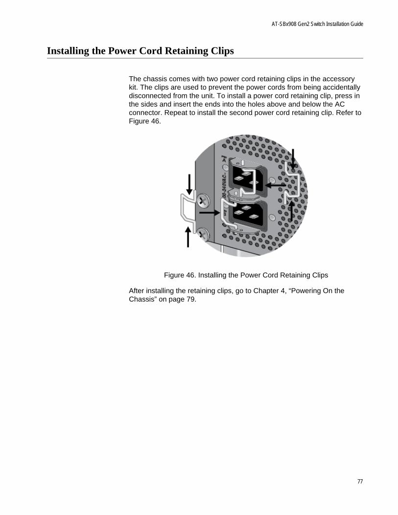
AT-SBx908 Gen2 Switch Installation Guide
Installing the Power Cord Retaining Clips
The chassis comes with two power cord retaining clips in the accessory kit. The clips are used to prevent the power cords from being accidentally disconnected from the unit. To install a power cord retaining clip, press in the sides and insert the ends into the holes above and below the AC connector. Repeat to install the second power cord retaining clip. Refer to Figure 46.
Figure 46. Installing the Power Cord Retaining Clips
After installing the retaining clips, go to Chapter 4, “Powering On the Chassis” on page 79.
77

Chapter 3: Installing the Chassis
78

Chapter 4
Powering On the Chassis
This chapter contains the following procedures:
“Verifying the Installation” on page 80
“Powering On AT-SBxPWRSYS2 Power Supplies” on page 81
“Powering On AT-SBxPWRSYS1-80 DC Power Supplies” on page 84
“Monitoring the Initialization Processes” on page 111
“Verifying the Hardware Operations of the Chassis” on page 114
79
Chapter 4: Powering On the Chassis
Verifying the Installation
Please perform the following procedure before powering on the chassis:
1. Verify that the chassis has at least one power supply in slot PSU A or B.
2. If the chassis has only one power supply, verify that the empty power supply slot on the front panel is covered with a blank panel. For instructions, refer to “Installing the Blank Power Supply Slot Cover” on page 75.
3. Verify that you installed the power cord retaining clips on the AC power connectors on the rear panel of the chassis. For instructions, refer to “Installing the Power Cord Retaining Clips” on page 77
4. Verify that the grounding lug on the back panel of the chassis is properly grounded. For instructions, refer to “Installing the Chassis Grounding Wire” on page 58.
5. Verify that all empty line card slots on the front panel of the chassis are covered with slot covers. If there are open slots, perform the procedure “Installing Blank Line Card Slot Covers” on page 73.
You may now power on the chassis. For instructions, refer to “Powering On AT-SBxPWRSYS2 Power Supplies” on page 81 or “Powering On AT-SBxPWRSYS1-80 DC Power Supplies” on page 84:
80
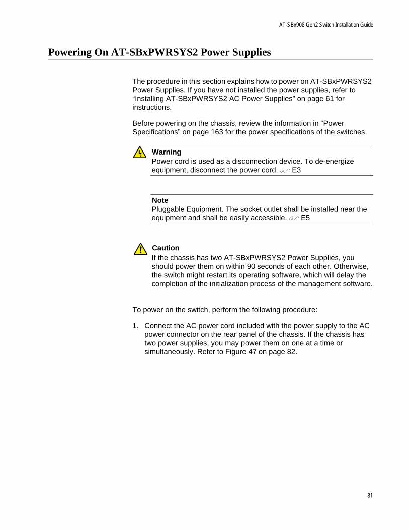
AT-SBx908 Gen2 Switch Installation Guide
Powering On AT-SBxPWRSYS2 Power Supplies
The procedure in this section explains how to power on AT-SBxPWRSYS2 Power Supplies. If you have not installed the power supplies, refer to “Installing AT-SBxPWRSYS2 AC Power Supplies” on page 61 for instructions.
Before powering on the chassis, review the information in “Power Specifications” on page 163 for the power specifications of the switches.
WarningPower cord is used as a disconnection device. To de-energize equipment, disconnect the power cord. E3
NotePluggable Equipment. The socket outlet shall be installed near the equipment and shall be easily accessible. E5
CautionIf the chassis has two AT-SBxPWRSYS2 Power Supplies, you should power them on within 90 seconds of each other. Otherwise, the switch might restart its operating software, which will delay the completion of the initialization process of the management software.
To power on the switch, perform the following procedure:
1. Connect the AC power cord included with the power supply to the AC power connector on the rear panel of the chassis. If the chassis has two power supplies, you may power them on one at a time or simultaneously. Refer to Figure 47 on page 82.
81
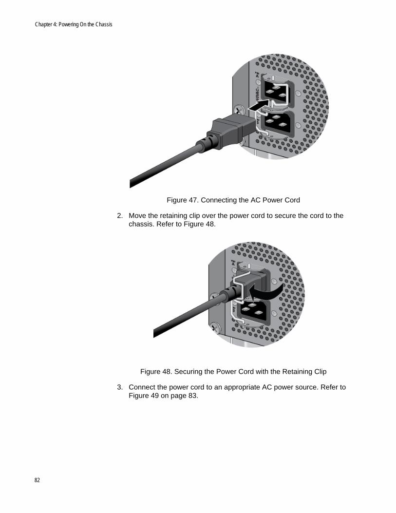
Chapter 4: Powering On the Chassis
Figure 47. Connecting the AC Power Cord
2. Move the retaining clip over the power cord to secure the cord to the chassis. Refer to Figure 48.
Figure 48. Securing the Power Cord with the Retaining Clip
3. Connect the power cord to an appropriate AC power source. Refer to Figure 49 on page 83.
82
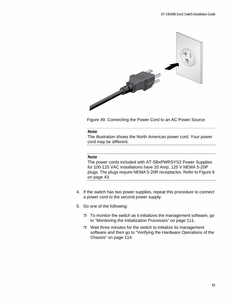
AT-SBx908 Gen2 Switch Installation Guide
Figure 49. Connecting the Power Cord to an AC Power Source
NoteThe illustration shows the North American power cord. Your power cord may be different.
NoteThe power cords included with AT-SBxPWRSYS2 Power Supplies for 100-125 VAC installations have 20 Amp, 125 V NEMA 5-20P plugs. The plugs require NEMA 5-20R receptacles. Refer to Figure 9 on page 43.
4. If the switch has two power supplies, repeat this procedure to connect a power cord to the second power supply.
5. Do one of the following:
To monitor the switch as it initializes the management software, go to “Monitoring the Initialization Processes” on page 111.
Wait three minutes for the switch to initialize its management software and then go to “Verifying the Hardware Operations of the Chassis” on page 114.
83

Chapter 4: Powering On the Chassis
Powering On AT-SBxPWRSYS1-80 DC Power Supplies
The procedure in this section explains how to power on AT-SBxPWRSYS1-80 DC Power Supplies. If you have not installed the power supplies, refer to “Installing AT-SBxPWRSYS1-80 DC Power Supplies” on page 65 for instructions.
Before powering on the chassis, review the information in “Power Specifications” on page 163 for the power specifications of the switches.
The power supply unit has a ground connection and positive and negative DC terminals. You may install the ground and power lead wires with the terminal lugs that come with the unit or with bare wire. The wire requirements are slightly different for terminal installation versus bare wire installation. Here are the wire requirements if you are using the terminals that come with the power supply:
Two 8 AWG stranded power wires (not provided)
One 10 AWG stranded grounding wire (not provided)
Here are the wire requirements for bare wire installation:
Two 8 AWG solid or stranded power wires (not provided)
One 10 AWG solid or stranded grounding wire (not provided)
Here is a list of the required tools:
Crimping tool (not provided)
8 mm wrench (not provided)
#1, #2, and #3 Phillips-head screwdrivers (not provided)
#3 Phillips-head 30 to 40 inch-lbs Phillips-head torque screwdriver (optional - not provided)
Here are the procedures for powering on AT-SBxPWRSYS1-80 DC Power Supplies:
“Choosing a Method for Attaching the Grounding Wire” on page 86
“Connecting the Grounding Wire with the Grounding Terminal” on page 86
“Connecting the Grounding Wire with Bare Wire” on page 91
“Choosing a Method for Attaching the Power Wires” on page 93
“Connecting the DC Power Wires with the Straight Terminals” on page 93
“Connecting the DC Power Wires with the Right Angle Terminals” on page 100
84
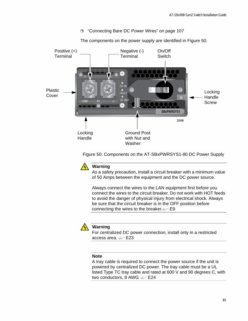
AT-SBx908 Gen2 Switch Installation Guide
“Connecting Bare DC Power Wires” on page 107
The components on the power supply are identified in Figure 50.
Figure 50. Components on the AT-SBxPWRSYS1-80 DC Power Supply
WarningAs a safety precaution, install a circuit breaker with a minimum value of 50 Amps between the equipment and the DC power source.
Always connect the wires to the LAN equipment first before you connect the wires to the circuit breaker. Do not work with HOT feeds to avoid the danger of physical injury from electrical shock. Always be sure that the circuit breaker is in the OFF position before connecting the wires to the breaker. E9
WarningFor centralized DC power connection, install only in a restricted access area. E23
NoteA tray cable is required to connect the power source if the unit is powered by centralized DC power. The tray cable must be a UL listed Type TC tray cable and rated at 600 V and 90 degrees C, with two conductors, 8 AWG. E24
Positive (+) Terminal
Negative (-) Terminal
On/Off Switch
Locking Handle
Locking Handle Screw
Plastic Cover
Ground Post with Nut and Washer
85
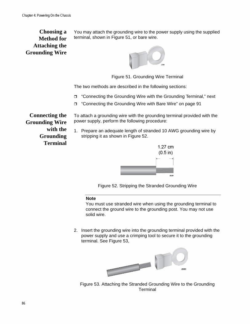
Chapter 4: Powering On the Chassis
Choosing aMethod for
Attaching theGrounding Wire
You may attach the grounding wire to the power supply using the supplied terminal, shown in Figure 51, or bare wire.
Figure 51. Grounding Wire Terminal
The two methods are described in the following sections:
“Connecting the Grounding Wire with the Grounding Terminal,” next
“Connecting the Grounding Wire with Bare Wire” on page 91
Connecting theGrounding Wire
with theGrounding
Terminal
To attach a grounding wire with the grounding terminal provided with the power supply, perform the following procedure:
1. Prepare an adequate length of stranded 10 AWG grounding wire by stripping it as shown in Figure 52.
Figure 52. Stripping the Stranded Grounding Wire
NoteYou must use stranded wire when using the grounding terminal to connect the ground wire to the grounding post. You may not use solid wire.
2. Insert the grounding wire into the grounding terminal provided with the power supply and use a crimping tool to secure it to the grounding terminal. See Figure 53,
Figure 53. Attaching the Stranded Grounding Wire to the Grounding Terminal
86
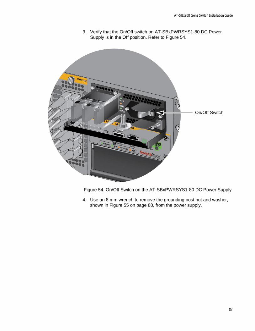
AT-SBx908 Gen2 Switch Installation Guide
3. Verify that the On/Off switch on AT-SBxPWRSYS1-80 DC Power Supply is in the Off position. Refer to Figure 54.
Figure 54. On/Off Switch on the AT-SBxPWRSYS1-80 DC Power Supply
4. Use an 8 mm wrench to remove the grounding post nut and washer, shown in Figure 55 on page 88, from the power supply.
On/Off Switch
87
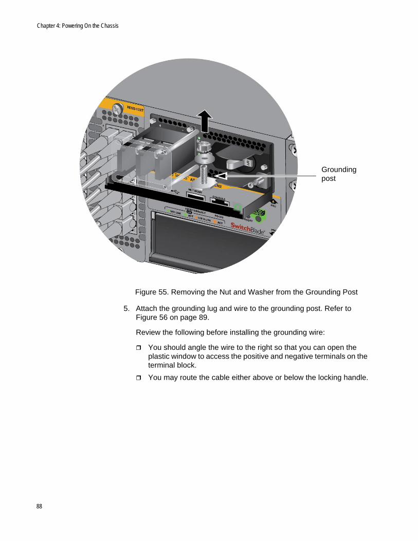
Chapter 4: Powering On the Chassis
Figure 55. Removing the Nut and Washer from the Grounding Post
5. Attach the grounding lug and wire to the grounding post. Refer to Figure 56 on page 89.
Review the following before installing the grounding wire:
You should angle the wire to the right so that you can open the plastic window to access the positive and negative terminals on the terminal block.
You may route the cable either above or below the locking handle.
Grounding post
88
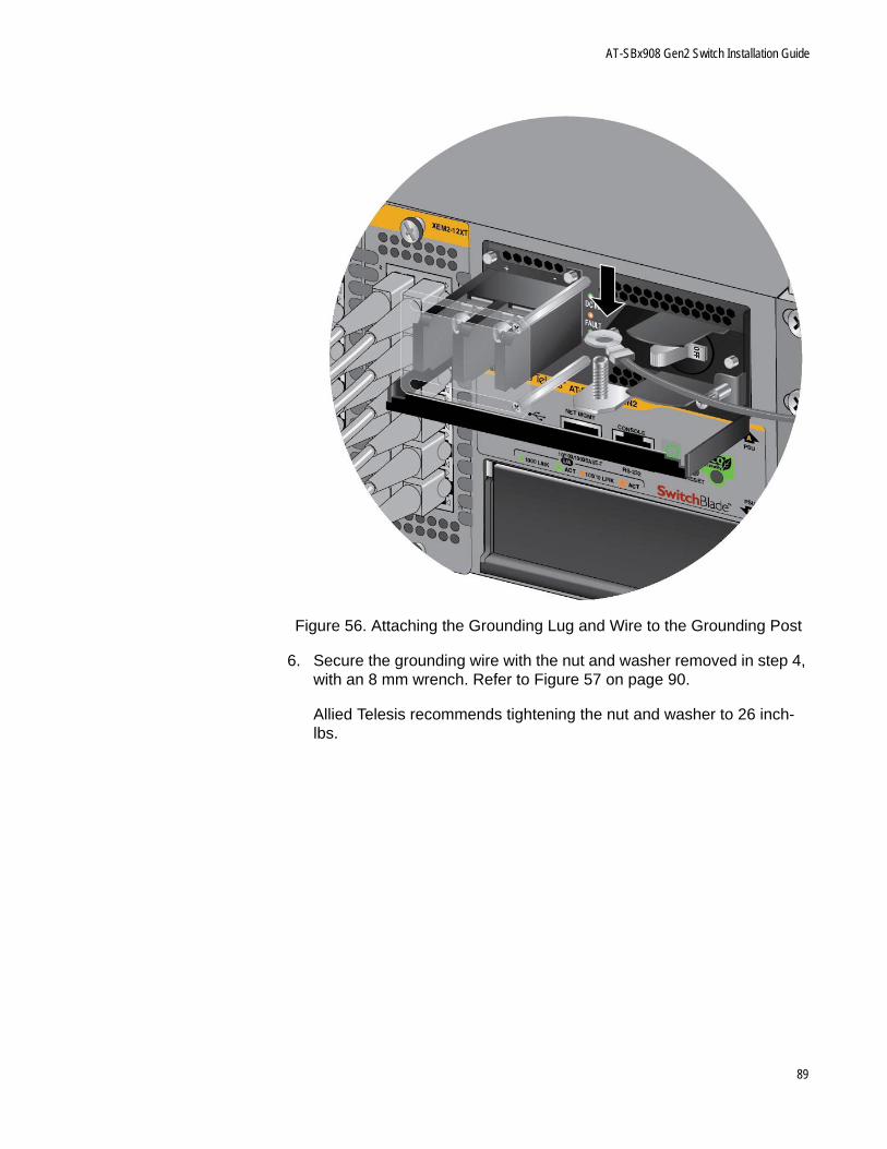
AT-SBx908 Gen2 Switch Installation Guide
Figure 56. Attaching the Grounding Lug and Wire to the Grounding Post
6. Secure the grounding wire with the nut and washer removed in step 4, with an 8 mm wrench. Refer to Figure 57 on page 90.
Allied Telesis recommends tightening the nut and washer to 26 inch-lbs.
89
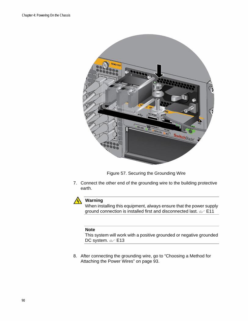
Chapter 4: Powering On the Chassis
Figure 57. Securing the Grounding Wire
7. Connect the other end of the grounding wire to the building protective earth.
WarningWhen installing this equipment, always ensure that the power supply ground connection is installed first and disconnected last. E11
NoteThis system will work with a positive grounded or negative grounded DC system. E13
8. After connecting the grounding wire, go to “Choosing a Method for Attaching the Power Wires” on page 93.
90
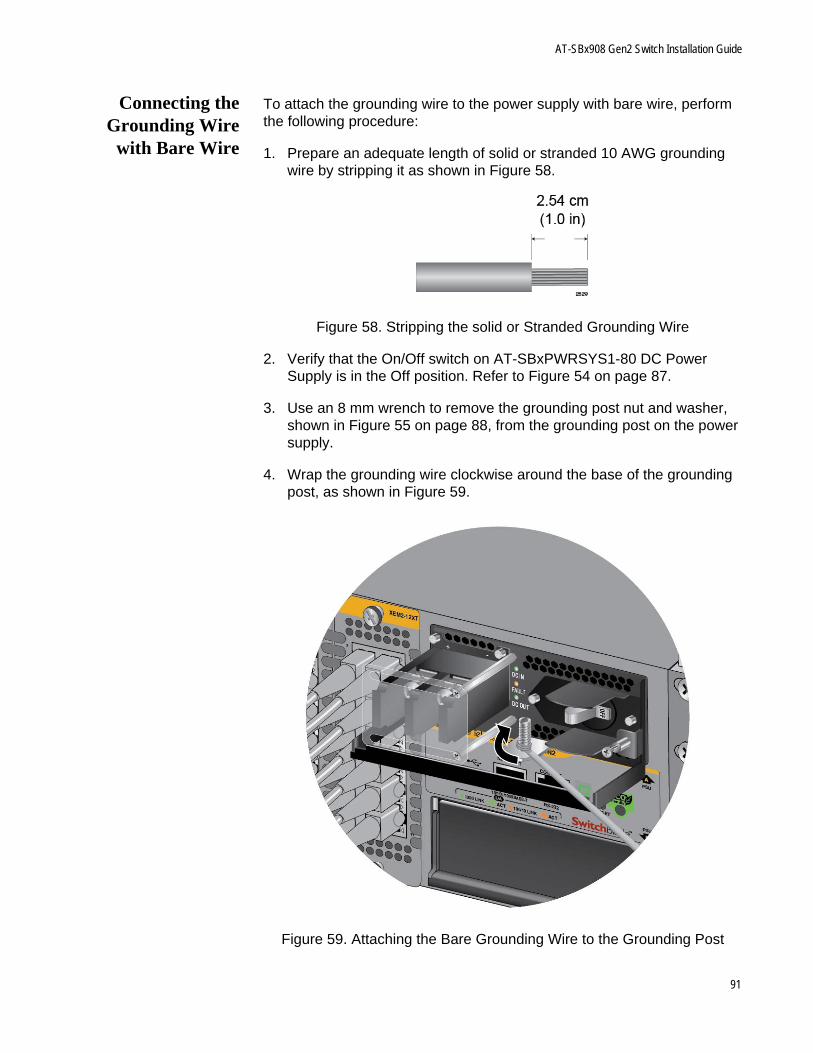
AT-SBx908 Gen2 Switch Installation Guide
Connecting theGrounding Wire
with Bare Wire
To attach the grounding wire to the power supply with bare wire, perform the following procedure:
1. Prepare an adequate length of solid or stranded 10 AWG grounding wire by stripping it as shown in Figure 58.
Figure 58. Stripping the solid or Stranded Grounding Wire
2. Verify that the On/Off switch on AT-SBxPWRSYS1-80 DC Power Supply is in the Off position. Refer to Figure 54 on page 87.
3. Use an 8 mm wrench to remove the grounding post nut and washer, shown in Figure 55 on page 88, from the grounding post on the power supply.
4. Wrap the grounding wire clockwise around the base of the grounding post, as shown in Figure 59.
Figure 59. Attaching the Bare Grounding Wire to the Grounding Post
91
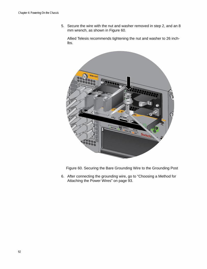
Chapter 4: Powering On the Chassis
5. Secure the wire with the nut and washer removed in step 2, and an 8 mm wrench, as shown in Figure 60.
Allied Telesis recommends tightening the nut and washer to 26 inch-lbs.
Figure 60. Securing the Bare Grounding Wire to the Grounding Post
6. After connecting the grounding wire, go to “Choosing a Method for Attaching the Power Wires” on page 93.
92
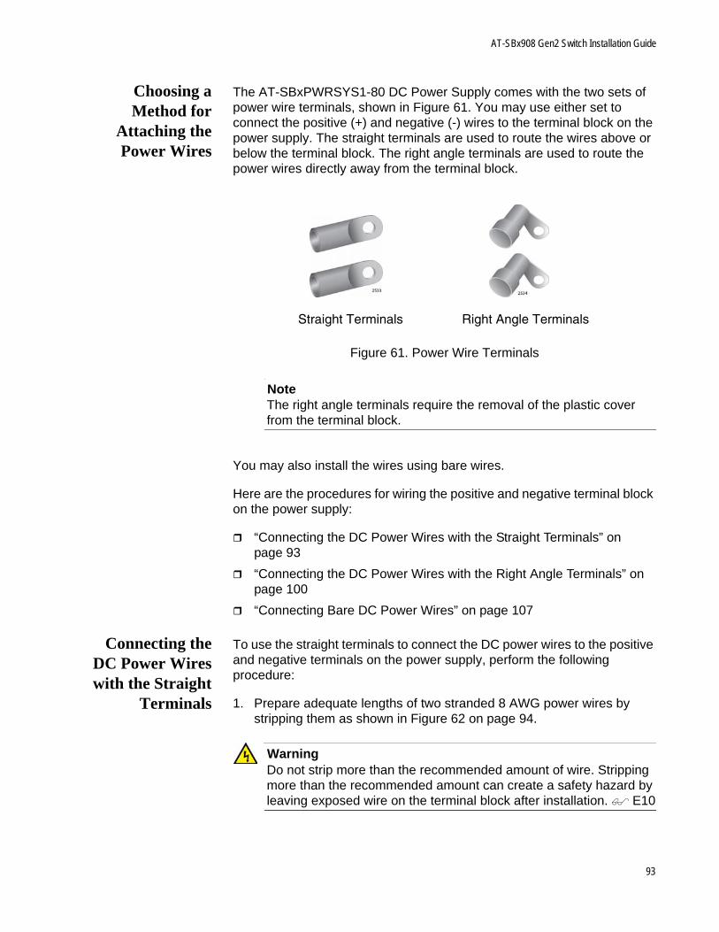
AT-SBx908 Gen2 Switch Installation Guide
Choosing aMethod for
Attaching thePower Wires
The AT-SBxPWRSYS1-80 DC Power Supply comes with the two sets of power wire terminals, shown in Figure 61. You may use either set to connect the positive (+) and negative (-) wires to the terminal block on the power supply. The straight terminals are used to route the wires above or below the terminal block. The right angle terminals are used to route the power wires directly away from the terminal block.
Figure 61. Power Wire Terminals
NoteThe right angle terminals require the removal of the plastic cover from the terminal block.
You may also install the wires using bare wires.
Here are the procedures for wiring the positive and negative terminal block on the power supply:
“Connecting the DC Power Wires with the Straight Terminals” on page 93
“Connecting the DC Power Wires with the Right Angle Terminals” on page 100
“Connecting Bare DC Power Wires” on page 107
Connecting theDC Power Wireswith the Straight
Terminals
To use the straight terminals to connect the DC power wires to the positive and negative terminals on the power supply, perform the following procedure:
1. Prepare adequate lengths of two stranded 8 AWG power wires by stripping them as shown in Figure 62 on page 94.
WarningDo not strip more than the recommended amount of wire. Stripping more than the recommended amount can create a safety hazard by leaving exposed wire on the terminal block after installation. E10
Straight Terminals Right Angle Terminals
93
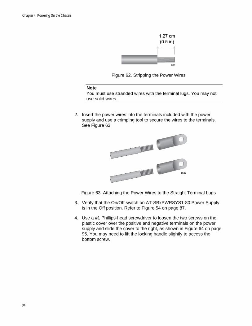
Chapter 4: Powering On the Chassis
Figure 62. Stripping the Power Wires
NoteYou must use stranded wires with the terminal lugs. You may not use solid wires.
2. Insert the power wires into the terminals included with the power supply and use a crimping tool to secure the wires to the terminals. See Figure 63.
Figure 63. Attaching the Power Wires to the Straight Terminal Lugs
3. Verify that the On/Off switch on AT-SBxPWRSYS1-80 Power Supply is in the Off position. Refer to Figure 54 on page 87.
4. Use a #1 Phillips-head screwdriver to loosen the two screws on the plastic cover over the positive and negative terminals on the power supply and slide the cover to the right, as shown in Figure 64 on page 95. You may need to lift the locking handle slightly to access the bottom screw.
94
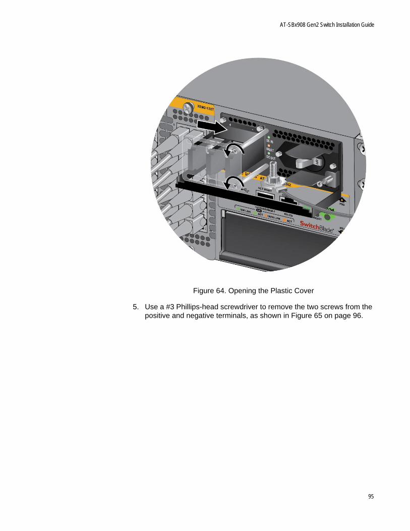
AT-SBx908 Gen2 Switch Installation Guide
Figure 64. Opening the Plastic Cover
5. Use a #3 Phillips-head screwdriver to remove the two screws from the positive and negative terminals, as shown in Figure 65 on page 96.
95
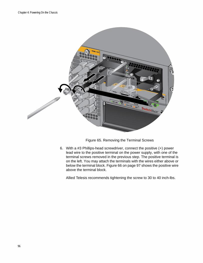
Chapter 4: Powering On the Chassis
Figure 65. Removing the Terminal Screws
6. With a #3 Phillips-head screwdriver, connect the positive (+) power lead wire to the positive terminal on the power supply, with one of the terminal screws removed in the previous step. The positive terminal is on the left. You may attach the terminals with the wires either above or below the terminal block. Figure 66 on page 97 shows the positive wire above the terminal block.
Allied Telesis recommends tightening the screw to 30 to 40 inch-lbs.
96
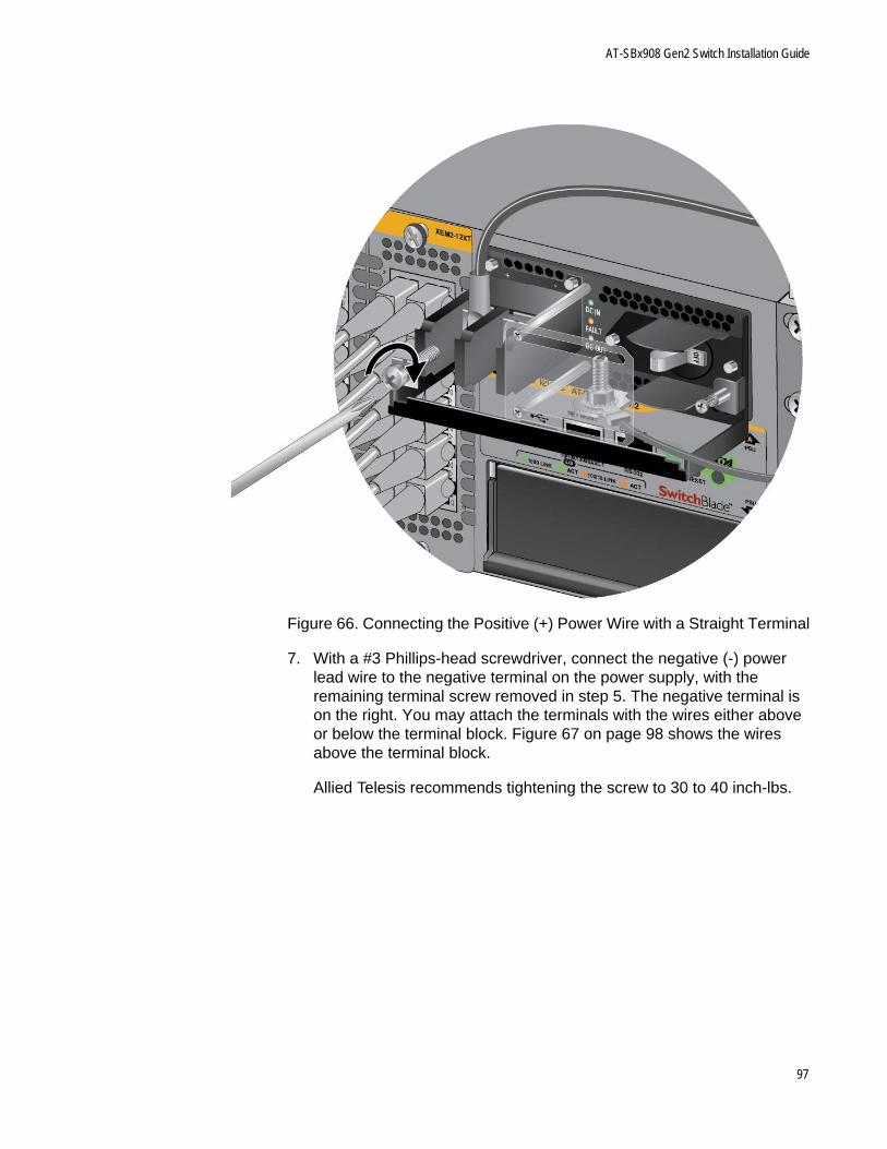
AT-SBx908 Gen2 Switch Installation Guide
Figure 66. Connecting the Positive (+) Power Wire with a Straight Terminal
7. With a #3 Phillips-head screwdriver, connect the negative (-) power lead wire to the negative terminal on the power supply, with the remaining terminal screw removed in step 5. The negative terminal is on the right. You may attach the terminals with the wires either above or below the terminal block. Figure 67 on page 98 shows the wires above the terminal block.
Allied Telesis recommends tightening the screw to 30 to 40 inch-lbs.
97
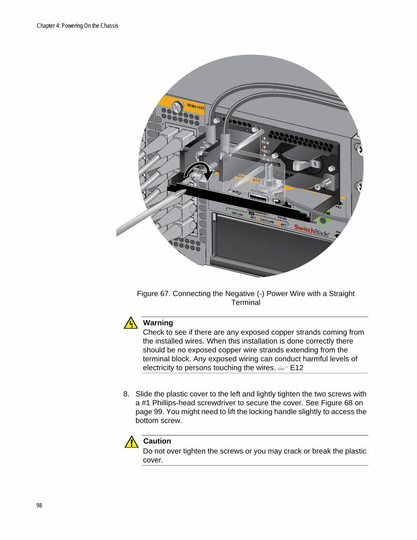
Chapter 4: Powering On the Chassis
Figure 67. Connecting the Negative (-) Power Wire with a Straight Terminal
WarningCheck to see if there are any exposed copper strands coming from the installed wires. When this installation is done correctly there should be no exposed copper wire strands extending from the terminal block. Any exposed wiring can conduct harmful levels of electricity to persons touching the wires. E12
8. Slide the plastic cover to the left and lightly tighten the two screws with a #1 Phillips-head screwdriver to secure the cover. See Figure 68 on page 99. You might need to lift the locking handle slightly to access the bottom screw.
CautionDo not over tighten the screws or you may crack or break the plastic cover.
98
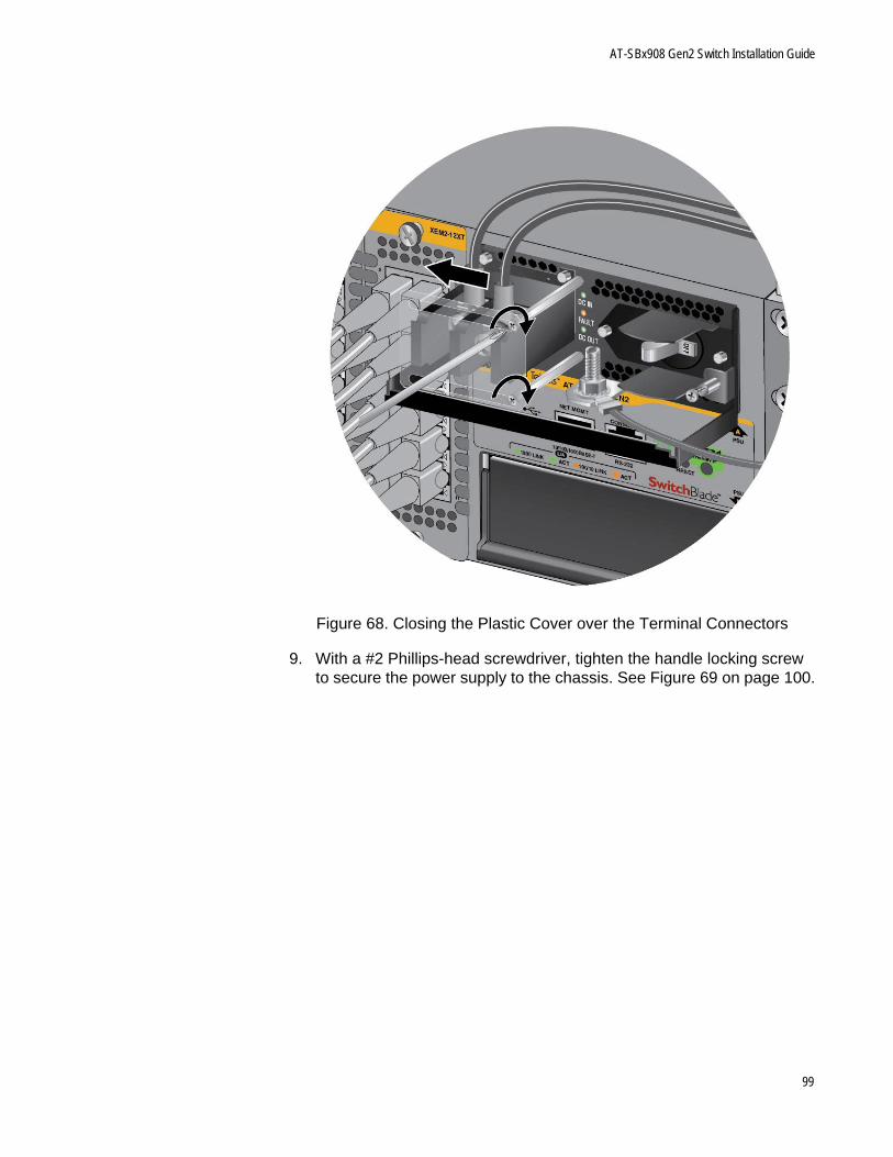
AT-SBx908 Gen2 Switch Installation Guide
Figure 68. Closing the Plastic Cover over the Terminal Connectors
9. With a #2 Phillips-head screwdriver, tighten the handle locking screw to secure the power supply to the chassis. See Figure 69 on page 100.
99
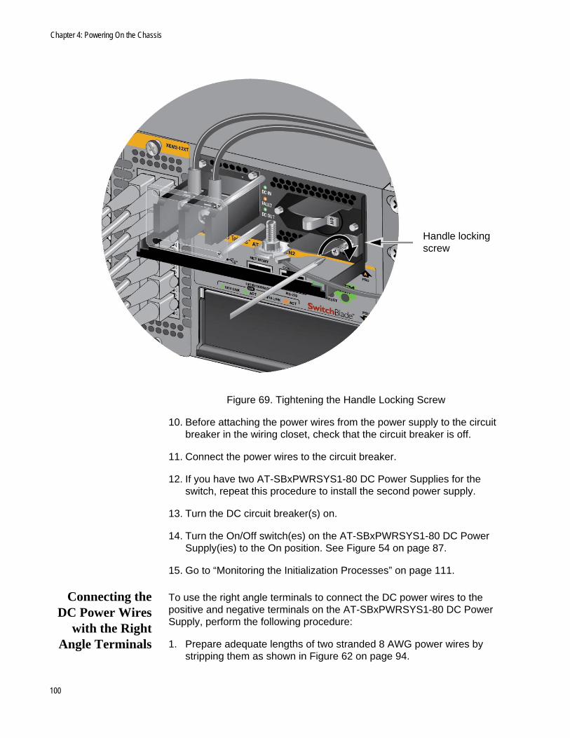
Chapter 4: Powering On the Chassis
Figure 69. Tightening the Handle Locking Screw
10. Before attaching the power wires from the power supply to the circuit breaker in the wiring closet, check that the circuit breaker is off.
11. Connect the power wires to the circuit breaker.
12. If you have two AT-SBxPWRSYS1-80 DC Power Supplies for the switch, repeat this procedure to install the second power supply.
13. Turn the DC circuit breaker(s) on.
14. Turn the On/Off switch(es) on the AT-SBxPWRSYS1-80 DC Power Supply(ies) to the On position. See Figure 54 on page 87.
15. Go to “Monitoring the Initialization Processes” on page 111.
Connecting theDC Power Wires
with the RightAngle Terminals
To use the right angle terminals to connect the DC power wires to the positive and negative terminals on the AT-SBxPWRSYS1-80 DC Power Supply, perform the following procedure:
1. Prepare adequate lengths of two stranded 8 AWG power wires by stripping them as shown in Figure 62 on page 94.
Handle locking screw
100
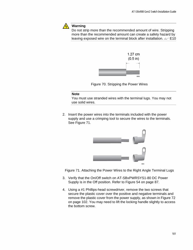
AT-SBx908 Gen2 Switch Installation Guide
WarningDo not strip more than the recommended amount of wire. Stripping more than the recommended amount can create a safety hazard by leaving exposed wire on the terminal block after installation. E10
Figure 70. Stripping the Power Wires
NoteYou must use stranded wires with the terminal lugs. You may not use solid wires.
2. Insert the power wires into the terminals included with the power supply and use a crimping tool to secure the wires to the terminals. See Figure 71.
Figure 71. Attaching the Power Wires to the Right Angle Terminal Lugs
3. Verify that the On/Off switch on AT-SBxPWRSYS1-80 DC Power Supply is in the Off position. Refer to Figure 54 on page 87.
4. Using a #1 Phillips-head screwdriver, remove the two screws that secure the plastic cover over the positive and negative terminals and remove the plastic cover from the power supply, as shown in Figure 72 on page 102. You may need to lift the locking handle slightly to access the bottom screw.
101
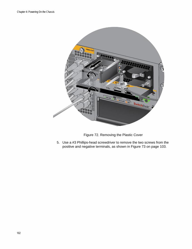
Chapter 4: Powering On the Chassis
Figure 72. Removing the Plastic Cover
5. Use a #3 Phillips-head screwdriver to remove the two screws from the positive and negative terminals, as shown in Figure 73 on page 103.
102
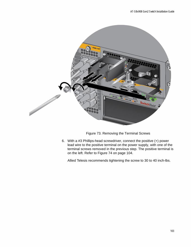
AT-SBx908 Gen2 Switch Installation Guide
Figure 73. Removing the Terminal Screws
6. With a #3 Phillips-head screwdriver, connect the positive (+) power lead wire to the positive terminal on the power supply, with one of the terminal screws removed in the previous step. The positive terminal is on the left. Refer to Figure 74 on page 104.
Allied Telesis recommends tightening the screw to 30 to 40 inch-lbs.
103
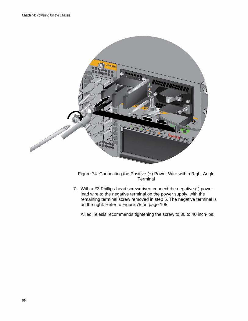
Chapter 4: Powering On the Chassis
Figure 74. Connecting the Positive (+) Power Wire with a Right Angle Terminal
7. With a #3 Phillips-head screwdriver, connect the negative (-) power lead wire to the negative terminal on the power supply, with the remaining terminal screw removed in step 5. The negative terminal is on the right. Refer to Figure 75 on page 105.
Allied Telesis recommends tightening the screw to 30 to 40 inch-lbs.
104
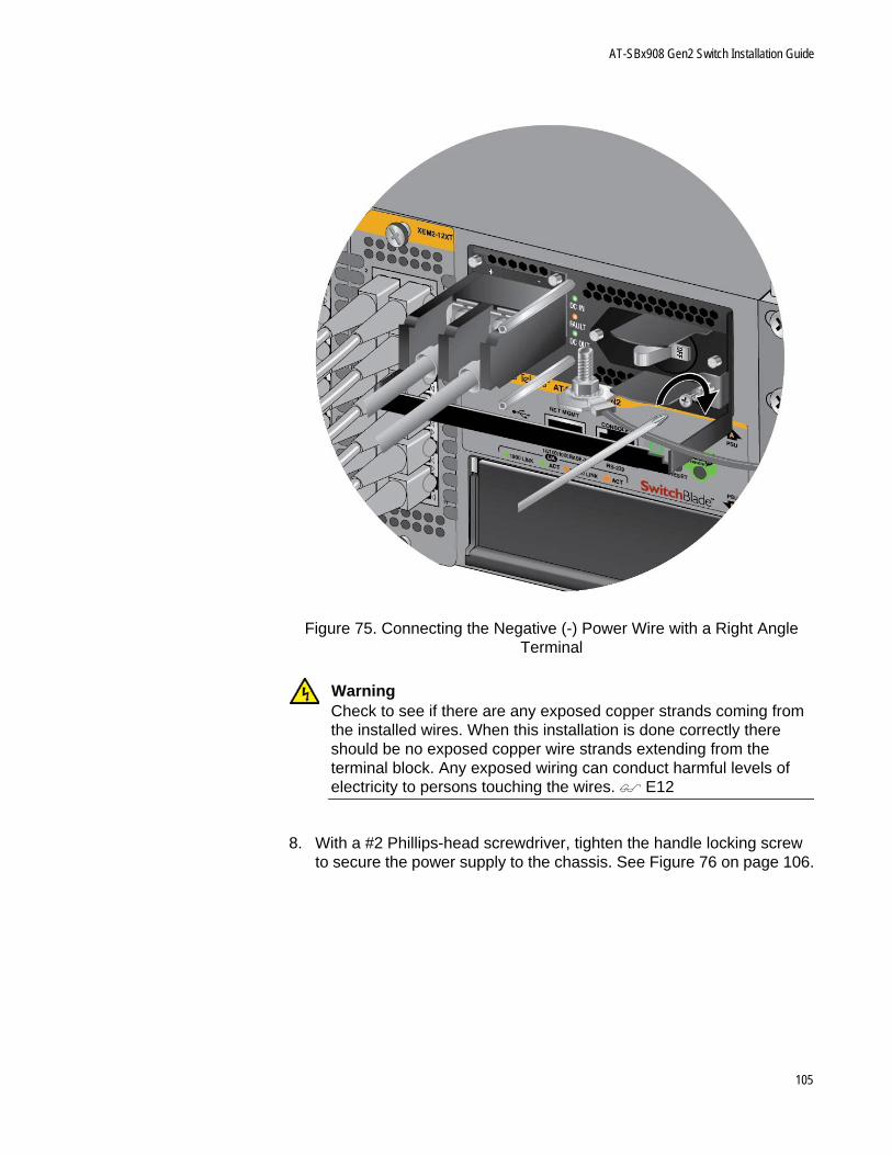
AT-SBx908 Gen2 Switch Installation Guide
Figure 75. Connecting the Negative (-) Power Wire with a Right Angle Terminal
WarningCheck to see if there are any exposed copper strands coming from the installed wires. When this installation is done correctly there should be no exposed copper wire strands extending from the terminal block. Any exposed wiring can conduct harmful levels of electricity to persons touching the wires. E12
8. With a #2 Phillips-head screwdriver, tighten the handle locking screw to secure the power supply to the chassis. See Figure 76 on page 106.
105
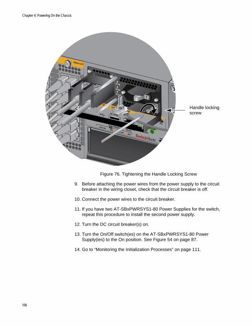
Chapter 4: Powering On the Chassis
Figure 76. Tightening the Handle Locking Screw
9. Before attaching the power wires from the power supply to the circuit breaker in the wiring closet, check that the circuit breaker is off.
10. Connect the power wires to the circuit breaker.
11. If you have two AT-SBxPWRSYS1-80 Power Supplies for the switch, repeat this procedure to install the second power supply.
12. Turn the DC circuit breaker(s) on.
13. Turn the On/Off switch(es) on the AT-SBxPWRSYS1-80 Power Supply(ies) to the On position. See Figure 54 on page 87.
14. Go to “Monitoring the Initialization Processes” on page 111.
Handle locking screw
106
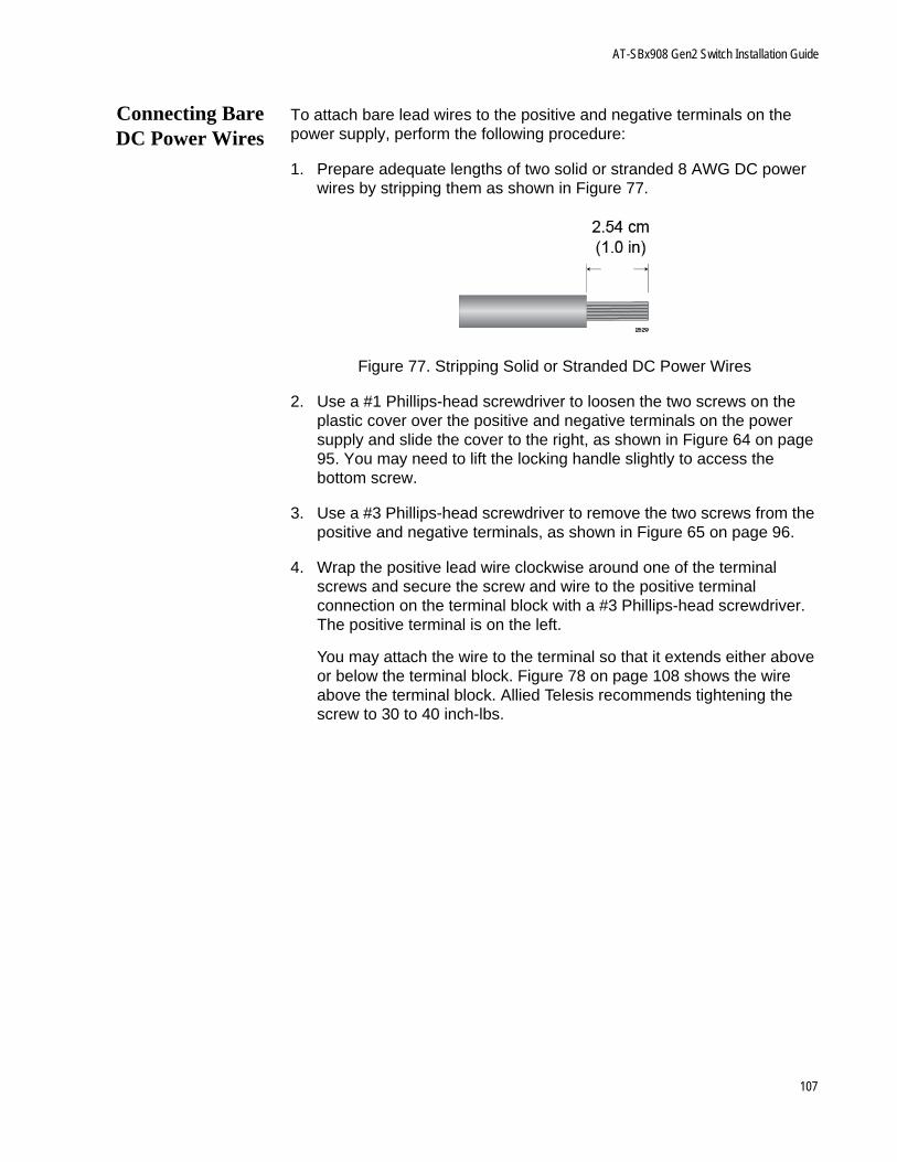
AT-SBx908 Gen2 Switch Installation Guide
Connecting BareDC Power Wires
To attach bare lead wires to the positive and negative terminals on the power supply, perform the following procedure:
1. Prepare adequate lengths of two solid or stranded 8 AWG DC power wires by stripping them as shown in Figure 77.
Figure 77. Stripping Solid or Stranded DC Power Wires
2. Use a #1 Phillips-head screwdriver to loosen the two screws on the plastic cover over the positive and negative terminals on the power supply and slide the cover to the right, as shown in Figure 64 on page 95. You may need to lift the locking handle slightly to access the bottom screw.
3. Use a #3 Phillips-head screwdriver to remove the two screws from the positive and negative terminals, as shown in Figure 65 on page 96.
4. Wrap the positive lead wire clockwise around one of the terminal screws and secure the screw and wire to the positive terminal connection on the terminal block with a #3 Phillips-head screwdriver. The positive terminal is on the left.
You may attach the wire to the terminal so that it extends either above or below the terminal block. Figure 78 on page 108 shows the wire above the terminal block. Allied Telesis recommends tightening the screw to 30 to 40 inch-lbs.
107
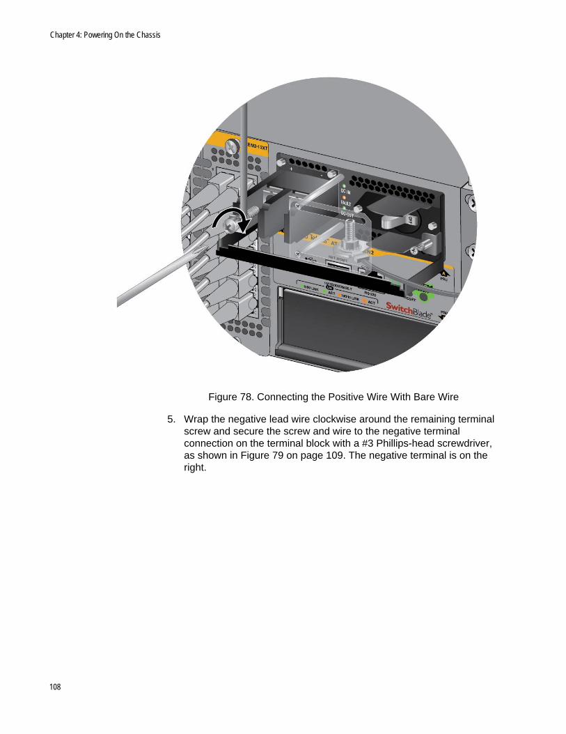
Chapter 4: Powering On the Chassis
Figure 78. Connecting the Positive Wire With Bare Wire
5. Wrap the negative lead wire clockwise around the remaining terminal screw and secure the screw and wire to the negative terminal connection on the terminal block with a #3 Phillips-head screwdriver, as shown in Figure 79 on page 109. The negative terminal is on the right.
108
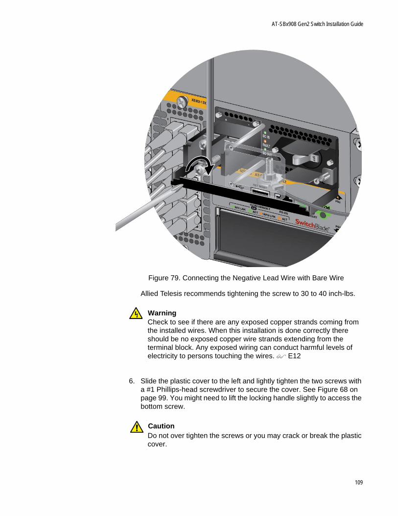
AT-SBx908 Gen2 Switch Installation Guide
Figure 79. Connecting the Negative Lead Wire with Bare Wire
Allied Telesis recommends tightening the screw to 30 to 40 inch-lbs.
WarningCheck to see if there are any exposed copper strands coming from the installed wires. When this installation is done correctly there should be no exposed copper wire strands extending from the terminal block. Any exposed wiring can conduct harmful levels of electricity to persons touching the wires. E12
6. Slide the plastic cover to the left and lightly tighten the two screws with a #1 Phillips-head screwdriver to secure the cover. See Figure 68 on page 99. You might need to lift the locking handle slightly to access the bottom screw.
CautionDo not over tighten the screws or you may crack or break the plastic cover.
109

Chapter 4: Powering On the Chassis
7. With a #2 Phillips-head screwdriver, tighten the handle locking screw to secure the power supply to the chassis. See Figure 76 on page 106.
8. Before attaching the power wires from the power supply to the circuit breaker in the wiring closet, check that the circuit breaker is off.
9. Connect the power wires to the circuit breaker.
10. If you have two AT-SBxPWRSYS1-80 DC Power Supplies for the switch, repeat this procedure to install the second power supply.
11. Turn the DC circuit breaker(s) on.
12. Turn the On/Off switch(es) on the AT-SBxPWRSYS1-80 DC Power Supply(ies) to the On position. See Figure 54 on page 87.
13. Go to “Monitoring the Initialization Processes” on page 111.
110
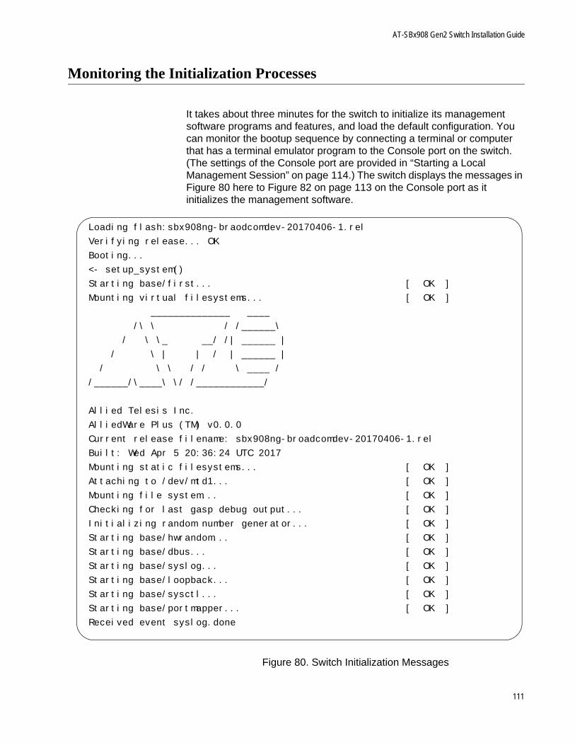
AT-SBx908 Gen2 Switch Installation Guide
Monitoring the Initialization Processes
It takes about three minutes for the switch to initialize its management software programs and features, and load the default configuration. You can monitor the bootup sequence by connecting a terminal or computer that has a terminal emulator program to the Console port on the switch. (The settings of the Console port are provided in “Starting a Local Management Session” on page 114.) The switch displays the messages in Figure 80 here to Figure 82 on page 113 on the Console port as it initializes the management software.
Figure 80. Switch Initialization Messages
Loading flash:sbx908ng-braodcomdev-20170406-1.rel
Verifying release... OK
Booting...
<- setup_system()
Starting base/first... [ OK ]
Mounting virtual filesystems... [ OK ]
______________ ____
/\ \ / /______\
/ \ \_ __/ /| ______ |
/ \ | | / | ______ |
/ \ \ / / \ ____ /
/______/\____\ \/ /____________/
Allied Telesis Inc.
AlliedWare Plus (TM) v0.0.0
Current release filename: sbx908ng-broadcomdev-20170406-1.rel
Built: Wed Apr 5 20:36:24 UTC 2017
Mounting static filesystems... [ OK ]
Attaching to /dev/mtd1... [ OK ]
Mounting file system... [ OK ]
Checking for last gasp debug output... [ OK ]
Initializing random number generator... [ OK ]
Starting base/hwrandom... [ OK ]
Starting base/dbus... [ OK ]
Starting base/syslog... [ OK ]
Starting base/loopback... [ OK ]
Starting base/sysctl... [ OK ]
Starting base/portmapper... [ OK ]
Received event syslog.done
111
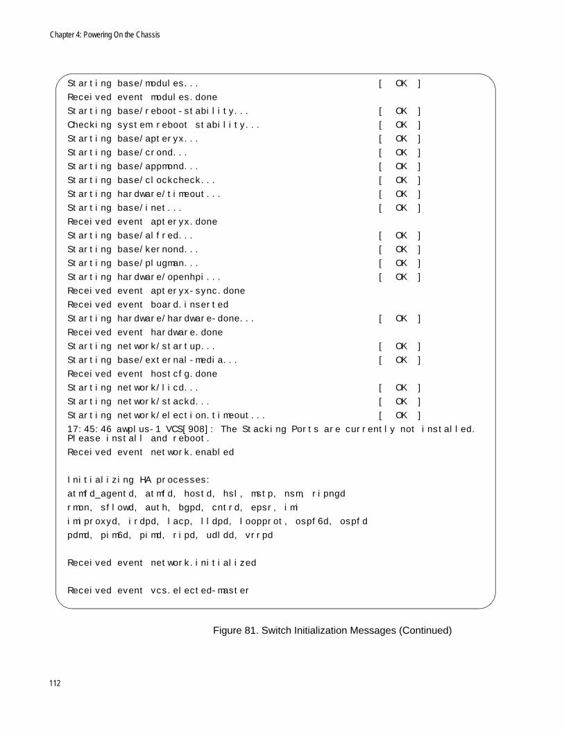
Chapter 4: Powering On the Chassis
Figure 81. Switch Initialization Messages (Continued)
Starting base/modules... [ OK ]
Received event modules.done
Starting base/reboot-stability... [ OK ]
Checking system reboot stability... [ OK ]
Starting base/apteryx... [ OK ]
Starting base/crond... [ OK ]
Starting base/appmond... [ OK ]
Starting base/clockcheck... [ OK ]
Starting hardware/timeout... [ OK ]
Starting base/inet... [ OK ]
Received event apteryx.done
Starting base/alfred... [ OK ]
Starting base/kernond... [ OK ]
Starting base/plugman... [ OK ]
Starting hardware/openhpi... [ OK ]
Received event apteryx-sync.done
Received event board.inserted
Starting hardware/hardware-done... [ OK ]
Received event hardware.done
Starting network/startup... [ OK ]
Starting base/external-media... [ OK ]
Received event hostcfg.done
Starting network/licd... [ OK ]
Starting network/stackd... [ OK ]
Starting network/election.timeout... [ OK ]
17:45:46 awplus-1 VCS[908]: The Stacking Ports are currently not installed. Please install and reboot.
Received event network.enabled
Initializing HA processes:
atmfd_agentd, atmfd, hostd, hsl, mstp, nsm, ripngd
rmon, sflowd, auth, bgpd, cntrd, epsr, imi
imiproxyd, irdpd, lacp, lldpd, loopprot, ospf6d, ospfd
pdmd, pim6d, pimd, ripd, udldd, vrrpd
Received event network.initialized
Received event vcs.elected-master
112
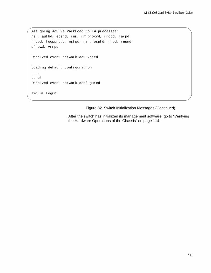
AT-SBx908 Gen2 Switch Installation Guide
Figure 82. Switch Initialization Messages (Continued)
After the switch has initialized its management software, go to “Verifying the Hardware Operations of the Chassis” on page 114.
Assigning Active Workload to HA processes:
hsl, authd, epsrd, imi, imiproxyd, irdpd, lacpd
lldpd, loopprotd, mstpd, nsm, ospfd, ripd, rmond
sflowd, vrrpd
Received event network.activated
Loading default configuration
....
done!
Received event network.configured
awplus login:
113
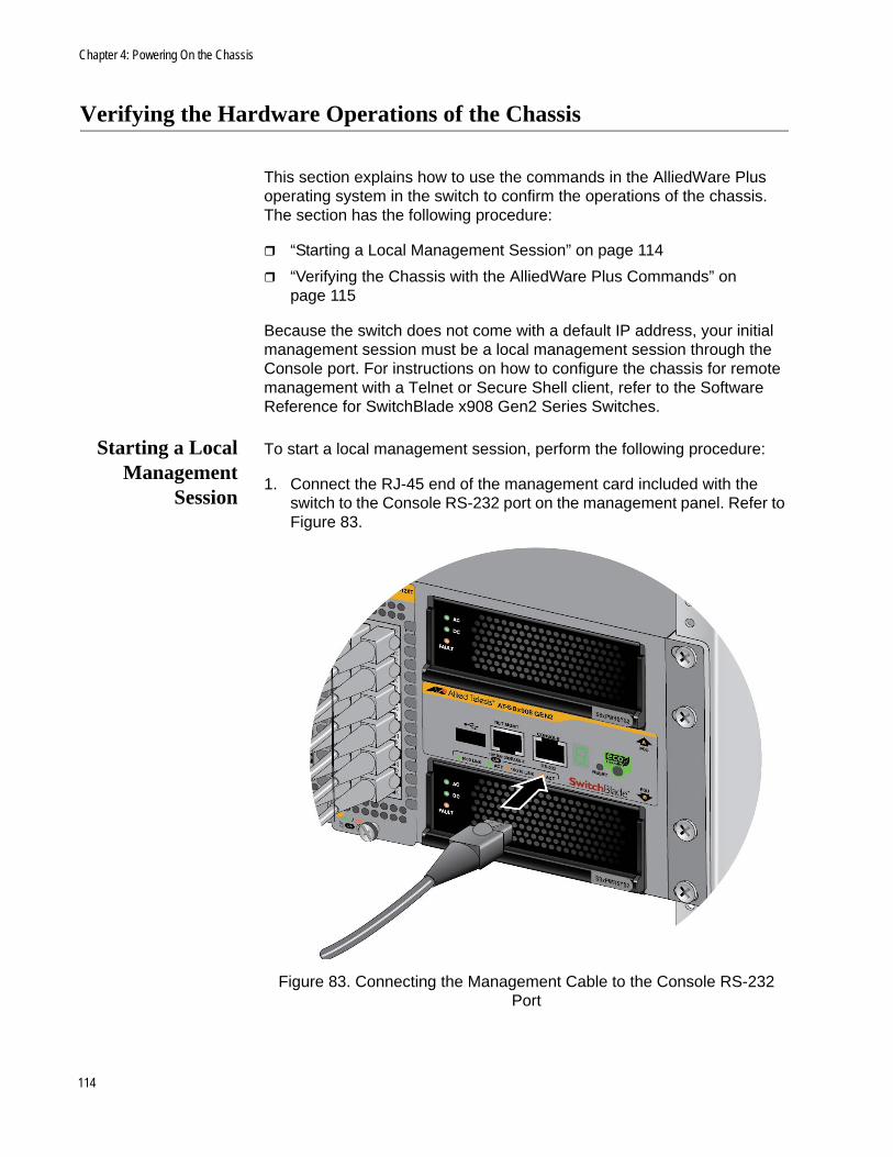
Chapter 4: Powering On the Chassis
Verifying the Hardware Operations of the Chassis
This section explains how to use the commands in the AlliedWare Plus operating system in the switch to confirm the operations of the chassis. The section has the following procedure:
“Starting a Local Management Session” on page 114
“Verifying the Chassis with the AlliedWare Plus Commands” on page 115
Because the switch does not come with a default IP address, your initial management session must be a local management session through the Console port. For instructions on how to configure the chassis for remote management with a Telnet or Secure Shell client, refer to the Software Reference for SwitchBlade x908 Gen2 Series Switches.
Starting a LocalManagement
Session
To start a local management session, perform the following procedure:
1. Connect the RJ-45 end of the management card included with the switch to the Console RS-232 port on the management panel. Refer to Figure 83.
Figure 83. Connecting the Management Cable to the Console RS-232 Port
114
AT-SBx908 Gen2 Switch Installation Guide
2. Connect the other end of the cable to an RS-232 port on a terminal or personal computer with a terminal emulation program.
3. Configure the VT-100 terminal or terminal emulation program as follows:
Baud rate: 115,200 bps
Data bits: 8
Parity: None
Stop bits: 1
Flow controller: None
NoteThe port settings are for a DEC VT100 or ANSI terminal, or an equivalent terminal emulator program.
4. Press Enter. You are prompted for a user name and password.
5. Enter the default user name and password. They are “manager” and “friend” (without the quotes), respectively
NoteUser names and passwords are case sensitive.
The local management session starts and the switch displays the prompt for the User Exec mode, “awplus>”.
Verifying theChassis with theAlliedWare Plus
Commands
To confirm the operations of the chassis with the commands in the AlliedWare Plus Operating System, perform the following procedure:
1. Start a local management session on the switch. For instructions, refer to “Starting a Local Management Session” on page 114.
2. To display the status of the power supplies and fan modules, enter the SHOW SYSTEM ENVIRONMENT command in the User Exec or Privileged Exec mode. The Status column in the display provides the states of the modules. Components are operating normally when they have an “Ok” status.
NoteThe next command, SHOW CARD, has to be performed from the Privileged Exec mode. If you are still in the User Exec mode, enter the ENABLE command to move to the Privileged Exec mode. The prompt for the mode is “awplus#”.
115
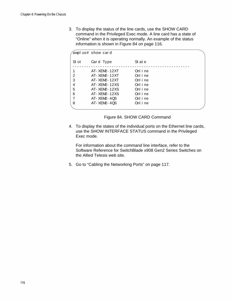
Chapter 4: Powering On the Chassis
3. To display the status of the line cards, use the SHOW CARD command in the Privileged Exec mode. A line card has a state of “Online” when it is operating normally. An example of the status information is shown in Figure 84 on page 116.
Figure 84. SHOW CARD Command
4. To display the states of the individual ports on the Ethernet line cards, use the SHOW INTERFACE STATUS command in the Privileged Exec mode.
For information about the command line interface, refer to the Software Reference for SwitchBlade x908 Gen2 Series Switches on the Allied Telesis web site.
5. Go to “Cabling the Networking Ports” on page 117.
awplus# show card
Slot Card Type State---------------------------------------------------1 AT-XEM2-12XT Online2 AT-XEM2-12XT Online3 AT-XEM2-12XT Online4 AT-XEM2-12XS Online5 AT-XEM2-12XS Online6 AT-XEM2-12XS Online7 AT-XEM2-4QS Online8 AT-XEM2-4QS Online
116
Chapter 5
Cabling the Networking Ports
This chapter contains the following procedures:
“Cabling the 1Gbps or 10Gbps Ports on the AT-XEM2-12XT Line Card” on page 118
“Guidelines to Handling SFP, SFP+, and QSFP+ Transceivers” on page 119
“Installing 1GBase SFP or 10GBase SFP+ Transceivers in AT-XEM2-12XS Line Cards” on page 120
“Installing AT-SP10TW Direct Connect Twinax Cables in the AT-XEM2-12XS Switch” on page 123
“Installing AT-QSFPSR4 or AT-QSFPLR4 Transceivers in QSFP+ Slots” on page 125
“Installing AT-QSFPCU Cables in QSFP+ Slots” on page 126
117

Chapter 5: Cabling the Networking Ports
Cabling the 1Gbps or 10Gbps Ports on the AT-XEM2-12XT Line Card
Here are the guidelines to cabling the 1Gbps/10Gbps twisted pair ports on the AT-XEM2-12XT Line Card:
The cable specifications for the ports are listed in Table 2 on page 23.
The connectors on the cables should fit snugly into the ports, and the tabs should lock the connectors into place.
The default speed setting for the ports is Auto-Negotiation. This setting is appropriate for ports connected to network devices that also support Auto-Negotiation.
The ports must be set to Auto-Negotiation, the default setting, to operate at 1Gbps.
The ports support full-duplex only.
Do not attach cables to ports of static or LACP port trunks until after configuring the trunks on the switch. Otherwise, the ports will form network loops that can adversely affect network performance.
118
AT-SBx908 Gen2 Switch Installation Guide
Guidelines to Handling SFP, SFP+, and QSFP+ Transceivers
Please review the following guidelines before installing SFP, SFP+, or QSFP+ transceivers in the line cards:
The transceivers are hot-swappable. You can install them while the switch is powered on.
For a list of supported transceivers, refer to the product data sheet on the Allied Telesis web site.
The operational specifications and fiber optic cable requirements of the transceivers are provided in the documents included with the devices.
You should install a transceiver before connecting its fiber optic cable.
Fiber optic transceivers are dust sensitive. Always keep the plug in the optical bores when a fiber optic cable is not installed, or when you store the transceiver. When you do remove the plug, keep it for future use.
Unnecessary removal and insertion of a transceiver can lead to premature failure.
CautionTransceivers can be damaged by static electricity. Be sure to observe all standard electrostatic discharge (ESD) precautions, such as wearing an antistatic wrist strap, to avoid damaging the devices. E92
119
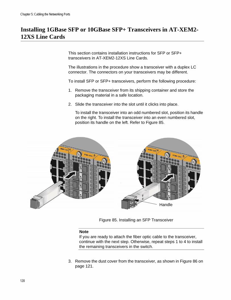
Chapter 5: Cabling the Networking Ports
Installing 1GBase SFP or 10GBase SFP+ Transceivers in AT-XEM2-12XS Line Cards
This section contains installation instructions for SFP or SFP+ transceivers in AT-XEM2-12XS Line Cards.
The illustrations in the procedure show a transceiver with a duplex LC connector. The connectors on your transceivers may be different.
To install SFP or SFP+ transceivers, perform the following procedure:
1. Remove the transceiver from its shipping container and store the packaging material in a safe location.
2. Slide the transceiver into the slot until it clicks into place.
To install the transceiver into an odd numbered slot, position its handle on the right. To install the transceiver into an even numbered slot, position its handle on the left. Refer to Figure 85.
Figure 85. Installing an SFP Transceiver
NoteIf you are ready to attach the fiber optic cable to the transceiver, continue with the next step. Otherwise, repeat steps 1 to 4 to install the remaining transceivers in the switch.
3. Remove the dust cover from the transceiver, as shown in Figure 86 on page 121.
Handle
120
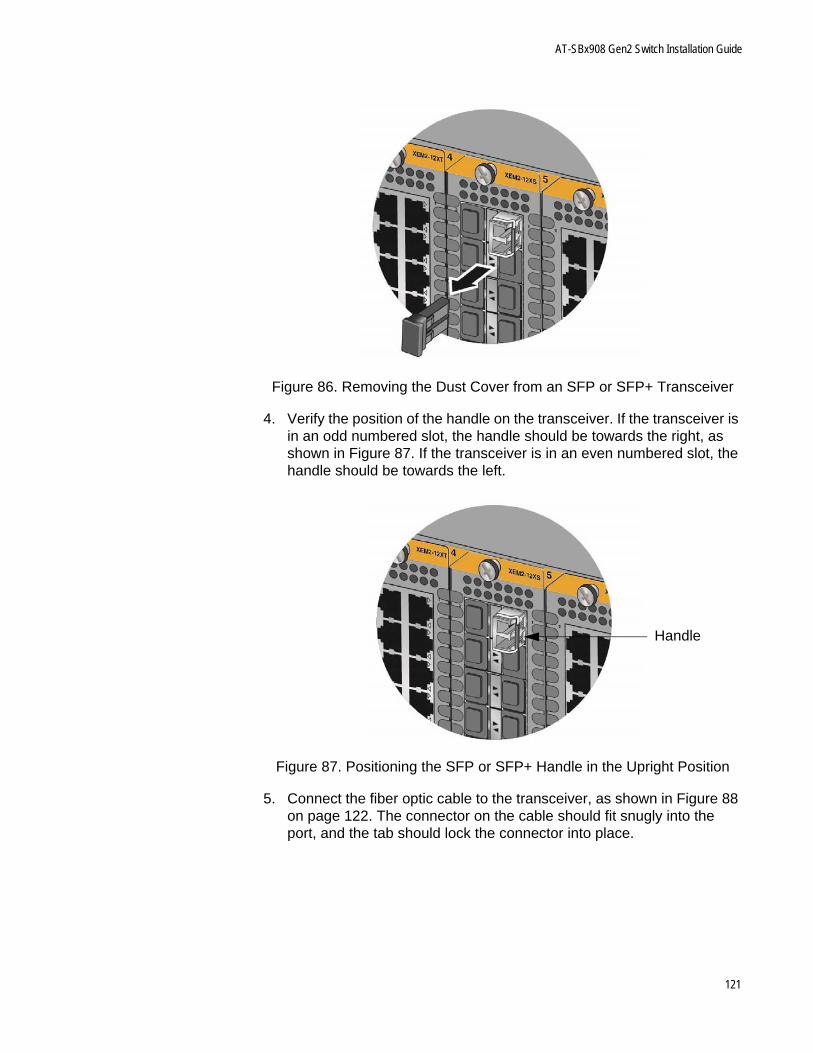
AT-SBx908 Gen2 Switch Installation Guide
Figure 86. Removing the Dust Cover from an SFP or SFP+ Transceiver
4. Verify the position of the handle on the transceiver. If the transceiver is in an odd numbered slot, the handle should be towards the right, as shown in Figure 87. If the transceiver is in an even numbered slot, the handle should be towards the left.
Figure 87. Positioning the SFP or SFP+ Handle in the Upright Position
5. Connect the fiber optic cable to the transceiver, as shown in Figure 88 on page 122. The connector on the cable should fit snugly into the port, and the tab should lock the connector into place.
Handle
121
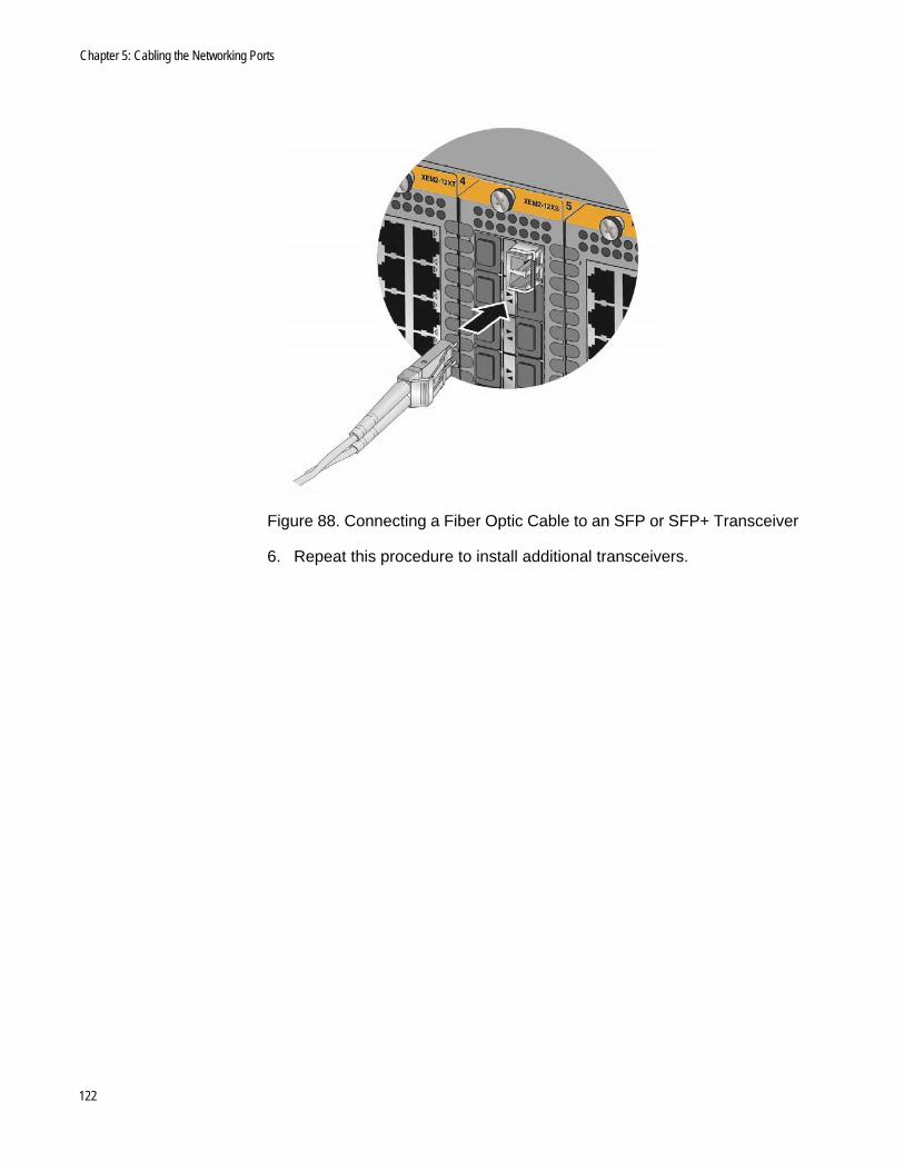
Chapter 5: Cabling the Networking Ports
Figure 88. Connecting a Fiber Optic Cable to an SFP or SFP+ Transceiver
6. Repeat this procedure to install additional transceivers.
122
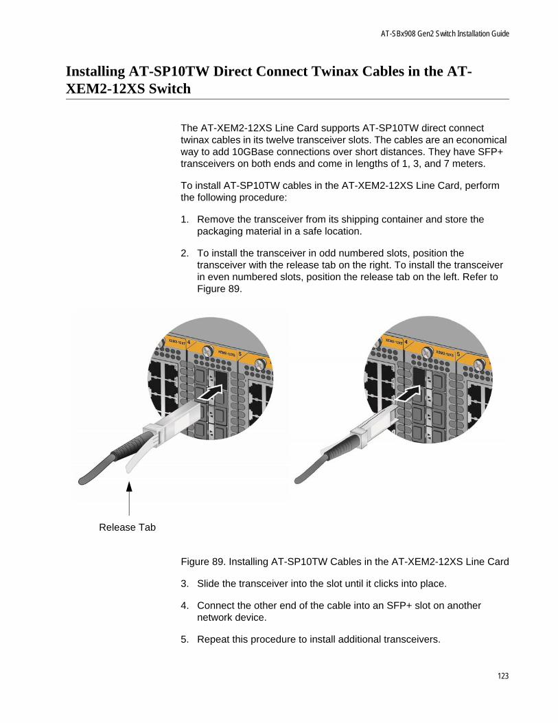
AT-SBx908 Gen2 Switch Installation Guide
Installing AT-SP10TW Direct Connect Twinax Cables in the AT-XEM2-12XS Switch
The AT-XEM2-12XS Line Card supports AT-SP10TW direct connect twinax cables in its twelve transceiver slots. The cables are an economical way to add 10GBase connections over short distances. They have SFP+ transceivers on both ends and come in lengths of 1, 3, and 7 meters.
To install AT-SP10TW cables in the AT-XEM2-12XS Line Card, perform the following procedure:
1. Remove the transceiver from its shipping container and store the packaging material in a safe location.
2. To install the transceiver in odd numbered slots, position the transceiver with the release tab on the right. To install the transceiver in even numbered slots, position the release tab on the left. Refer to Figure 89.
Figure 89. Installing AT-SP10TW Cables in the AT-XEM2-12XS Line Card
3. Slide the transceiver into the slot until it clicks into place.
4. Connect the other end of the cable into an SFP+ slot on another network device.
5. Repeat this procedure to install additional transceivers.
Release Tab
123

Chapter 5: Cabling the Networking Ports
NoteTo remove the connector and cable from the slot, gently push on the connector, pull on the release tab, and slide the connector from the slot.
124
AT-SBx908 Gen2 Switch Installation Guide
Installing AT-QSFPSR4 or AT-QSFPLR4 Transceivers in QSFP+ Slots
This section contains the procedure for installing AT-QSFPSR4 or AT-QSFPLR4 transceivers in the four QSFP+ slots in the AT-XEM2-4QS Line Card.
Please review “Guidelines to Handling SFP, SFP+, and QSFP+ Transceivers” on page 119 before performing this procedure.
To install AT-QSFPSR4 or AT-QSFPLR4 transceivers, perform the following procedure:
1. Remove the dust cover from a QSFP+ slot. Refer to Figure 90 on page 126.
2. Slide a QSFP+ transceiver into the slot until it clicks into place.
3. Attach a fiber optic cable to the transceiver.
4. Connect the other end of the cable to a compatible QSFP+ port in another network device.
5. Repeat this procedure to install additional QSFP+ transceiver.
NoteTo remove the connector and cable from the slot, gently push on the connector, pull on the release tab, and slide the connector from the slot.
125
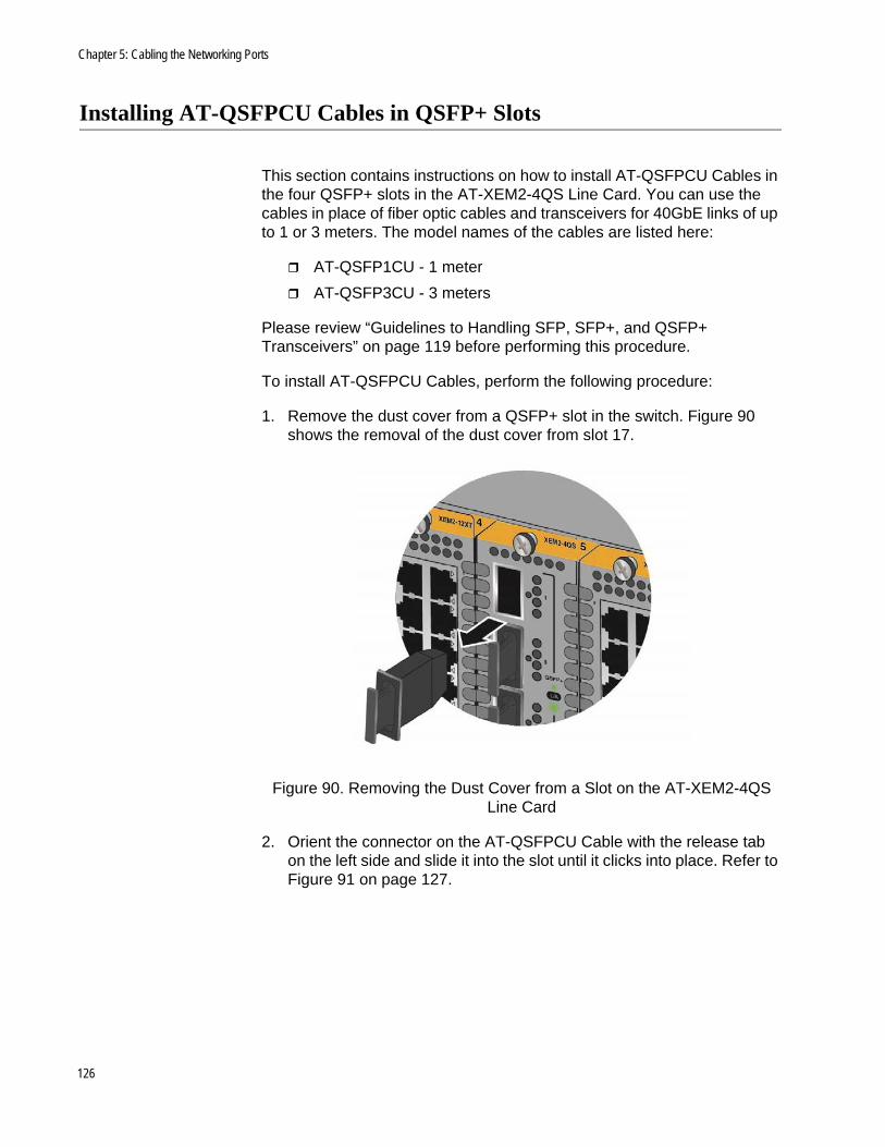
Chapter 5: Cabling the Networking Ports
Installing AT-QSFPCU Cables in QSFP+ Slots
This section contains instructions on how to install AT-QSFPCU Cables in the four QSFP+ slots in the AT-XEM2-4QS Line Card. You can use the cables in place of fiber optic cables and transceivers for 40GbE links of up to 1 or 3 meters. The model names of the cables are listed here:
AT-QSFP1CU - 1 meter
AT-QSFP3CU - 3 meters
Please review “Guidelines to Handling SFP, SFP+, and QSFP+ Transceivers” on page 119 before performing this procedure.
To install AT-QSFPCU Cables, perform the following procedure:
1. Remove the dust cover from a QSFP+ slot in the switch. Figure 90 shows the removal of the dust cover from slot 17.
Figure 90. Removing the Dust Cover from a Slot on the AT-XEM2-4QS Line Card
2. Orient the connector on the AT-QSFPCU Cable with the release tab on the left side and slide it into the slot until it clicks into place. Refer to Figure 91 on page 127.
126
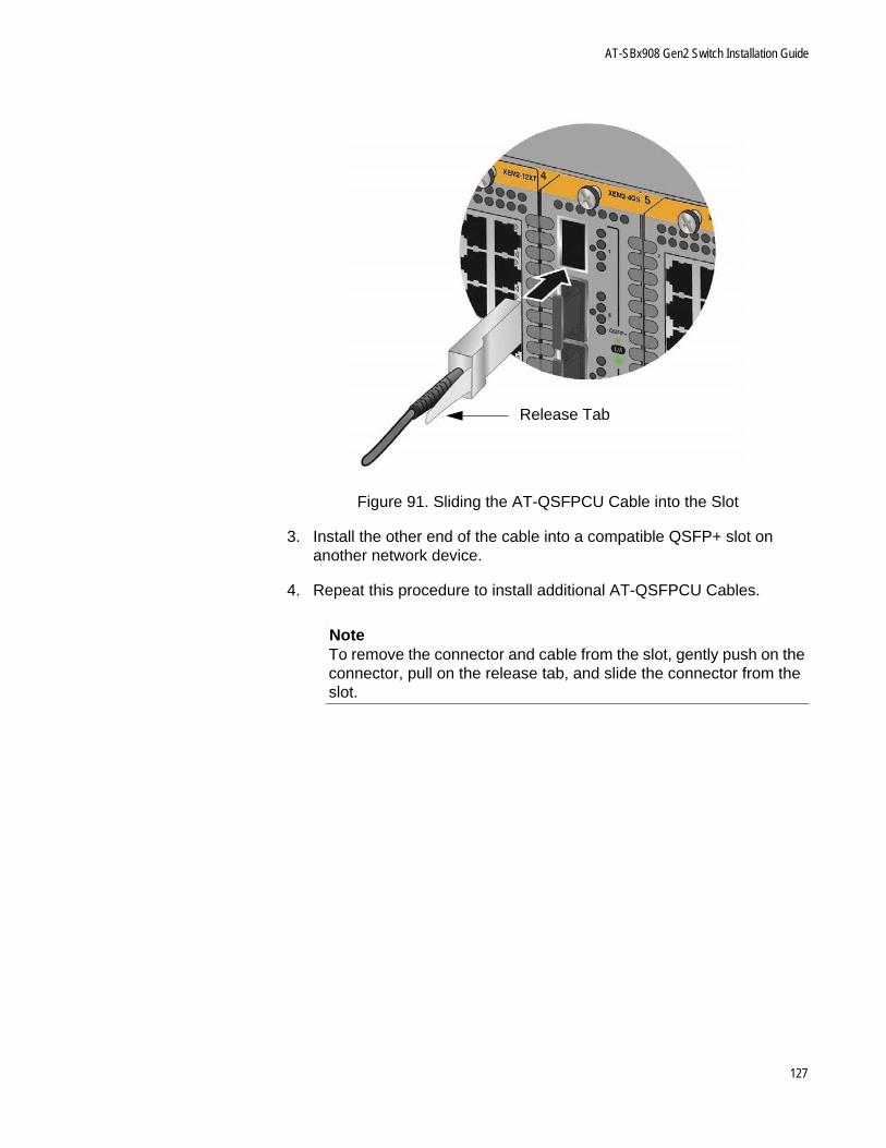
AT-SBx908 Gen2 Switch Installation Guide
Figure 91. Sliding the AT-QSFPCU Cable into the Slot
3. Install the other end of the cable into a compatible QSFP+ slot on another network device.
4. Repeat this procedure to install additional AT-QSFPCU Cables.
NoteTo remove the connector and cable from the slot, gently push on the connector, pull on the release tab, and slide the connector from the slot.
Release Tab
127

Chapter 5: Cabling the Networking Ports
128
Chapter 6
Replacing Modules
This chapter contains the following procedures:
“Replacing AT-SBxPWRSYS2 AC Power Supplies” on page 130
“Replacing AT-SBxPWRSYS1-80 DC Power Supplies” on page 134
“Removing Ethernet Line Cards” on page 145
“Replacing AT-FAN08 Modules” on page 150
129
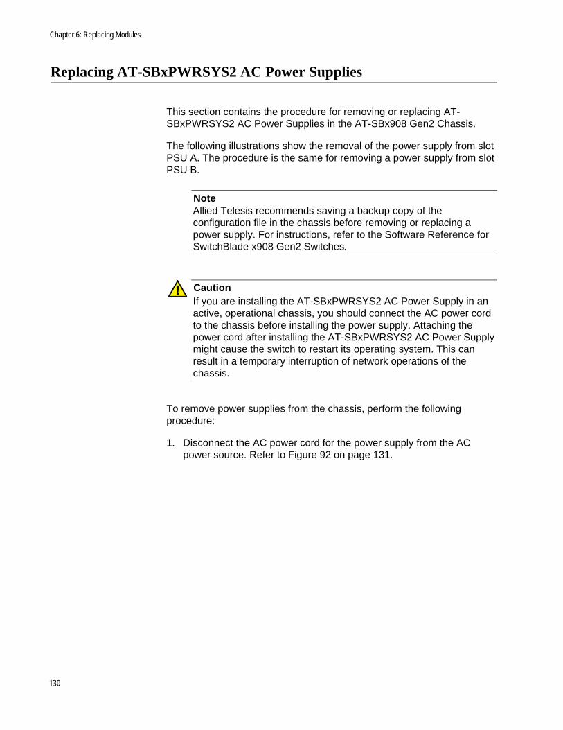
Chapter 6: Replacing Modules
Replacing AT-SBxPWRSYS2 AC Power Supplies
This section contains the procedure for removing or replacing AT-SBxPWRSYS2 AC Power Supplies in the AT-SBx908 Gen2 Chassis.
The following illustrations show the removal of the power supply from slot PSU A. The procedure is the same for removing a power supply from slot PSU B.
NoteAllied Telesis recommends saving a backup copy of the configuration file in the chassis before removing or replacing a power supply. For instructions, refer to the Software Reference for SwitchBlade x908 Gen2 Switches.
CautionIf you are installing the AT-SBxPWRSYS2 AC Power Supply in an active, operational chassis, you should connect the AC power cord to the chassis before installing the power supply. Attaching the power cord after installing the AT-SBxPWRSYS2 AC Power Supply might cause the switch to restart its operating system. This can result in a temporary interruption of network operations of the chassis.
To remove power supplies from the chassis, perform the following procedure:
1. Disconnect the AC power cord for the power supply from the AC power source. Refer to Figure 92 on page 131.
130
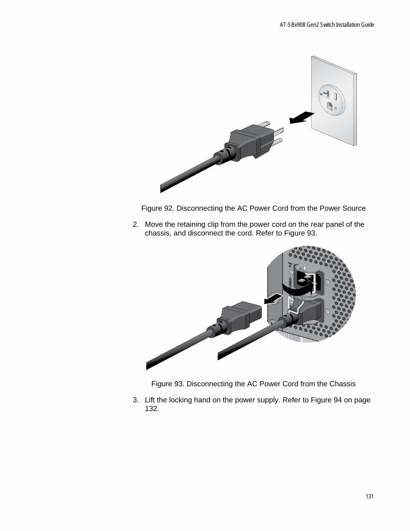
AT-SBx908 Gen2 Switch Installation Guide
Figure 92. Disconnecting the AC Power Cord from the Power Source
2. Move the retaining clip from the power cord on the rear panel of the chassis, and disconnect the cord. Refer to Figure 93.
Figure 93. Disconnecting the AC Power Cord from the Chassis
3. Lift the locking hand on the power supply. Refer to Figure 94 on page 132.
131
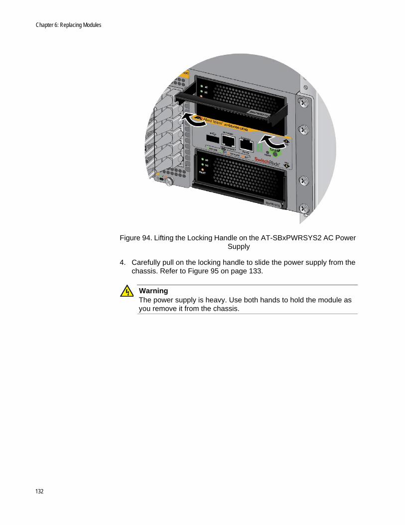
Chapter 6: Replacing Modules
Figure 94. Lifting the Locking Handle on the AT-SBxPWRSYS2 AC Power Supply
4. Carefully pull on the locking handle to slide the power supply from the chassis. Refer to Figure 95 on page 133.
WarningThe power supply is heavy. Use both hands to hold the module as you remove it from the chassis.
132
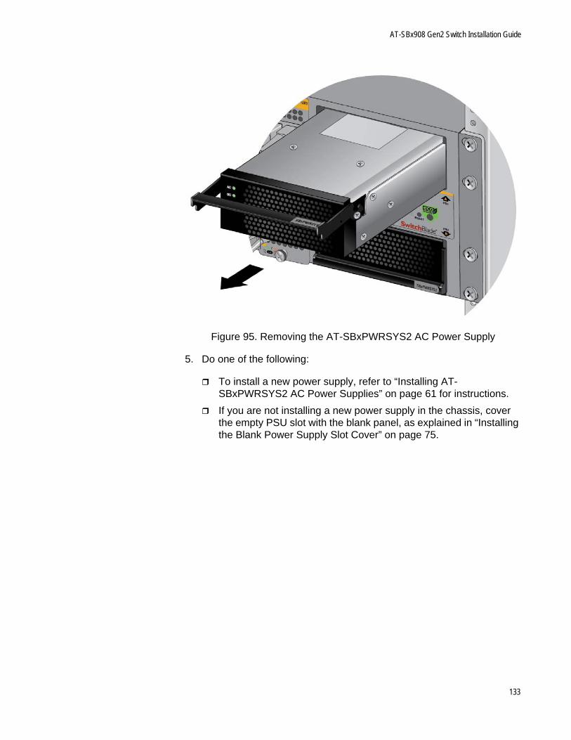
AT-SBx908 Gen2 Switch Installation Guide
Figure 95. Removing the AT-SBxPWRSYS2 AC Power Supply
5. Do one of the following:
To install a new power supply, refer to “Installing AT-SBxPWRSYS2 AC Power Supplies” on page 61 for instructions.
If you are not installing a new power supply in the chassis, cover the empty PSU slot with the blank panel, as explained in “Installing the Blank Power Supply Slot Cover” on page 75.
133
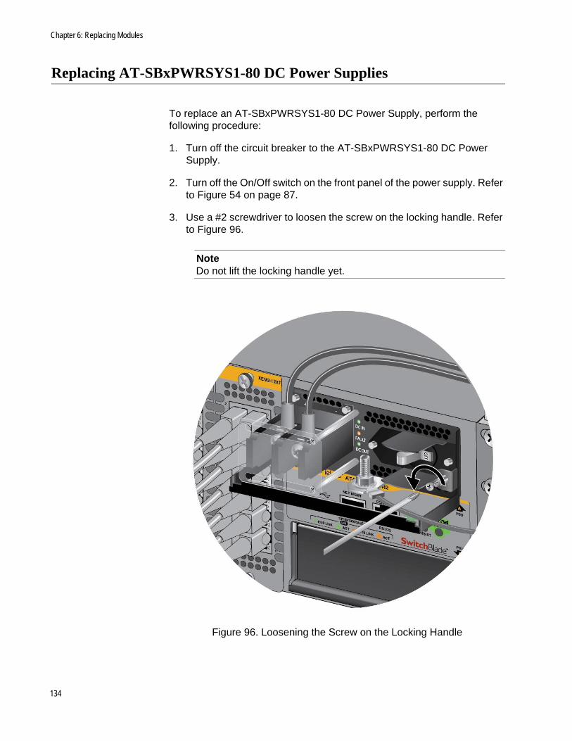
Chapter 6: Replacing Modules
Replacing AT-SBxPWRSYS1-80 DC Power Supplies
To replace an AT-SBxPWRSYS1-80 DC Power Supply, perform the following procedure:
1. Turn off the circuit breaker to the AT-SBxPWRSYS1-80 DC Power Supply.
2. Turn off the On/Off switch on the front panel of the power supply. Refer to Figure 54 on page 87.
3. Use a #2 screwdriver to loosen the screw on the locking handle. Refer to Figure 96.
NoteDo not lift the locking handle yet.
Figure 96. Loosening the Screw on the Locking Handle
134
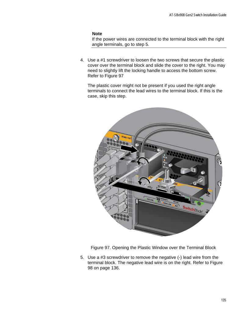
AT-SBx908 Gen2 Switch Installation Guide
NoteIf the power wires are connected to the terminal block with the right angle terminals, go to step 5.
4. Use a #1 screwdriver to loosen the two screws that secure the plastic cover over the terminal block and slide the cover to the right. You may need to slightly lift the locking handle to access the bottom screw. Refer to Figure 97
The plastic cover might not be present if you used the right angle terminals to connect the lead wires to the terminal block. If this is the case, skip this step.
Figure 97. Opening the Plastic Window over the Terminal Block
5. Use a #3 screwdriver to remove the negative (-) lead wire from the terminal block. The negative lead wire is on the right. Refer to Figure 98 on page 136.
135
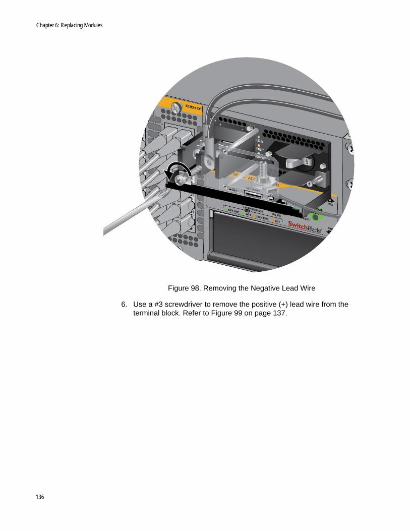
Chapter 6: Replacing Modules
Figure 98. Removing the Negative Lead Wire
6. Use a #3 screwdriver to remove the positive (+) lead wire from the terminal block. Refer to Figure 99 on page 137.
136
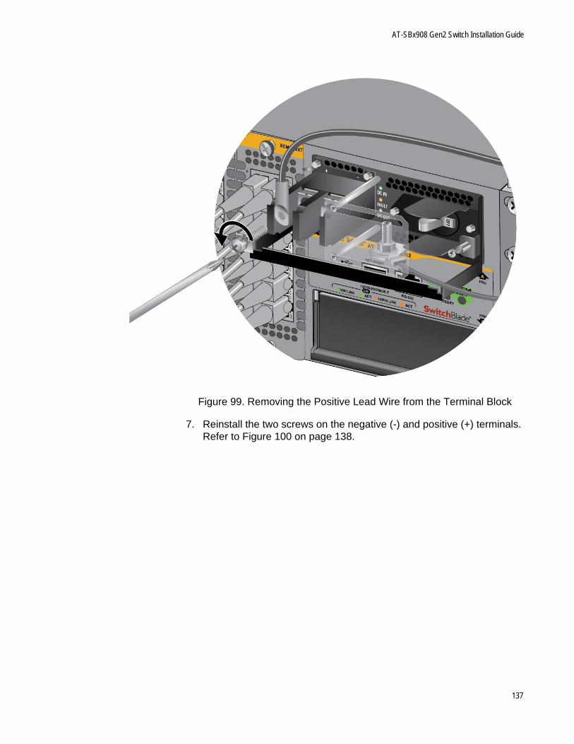
AT-SBx908 Gen2 Switch Installation Guide
Figure 99. Removing the Positive Lead Wire from the Terminal Block
7. Reinstall the two screws on the negative (-) and positive (+) terminals. Refer to Figure 100 on page 138.
137
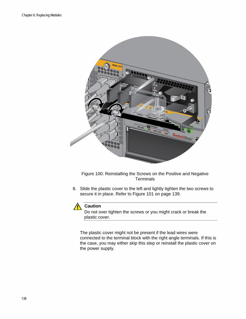
Chapter 6: Replacing Modules
Figure 100. Reinstalling the Screws on the Positive and Negative Terminals
8. Slide the plastic cover to the left and lightly tighten the two screws to secure it in place. Refer to Figure 101 on page 139.
CautionDo not over tighten the screws or you might crack or break the plastic cover.
The plastic cover might not be present if the lead wires were connected to the terminal block with the right angle terminals. If this is the case, you may either skip this step or reinstall the plastic cover on the power supply.
138
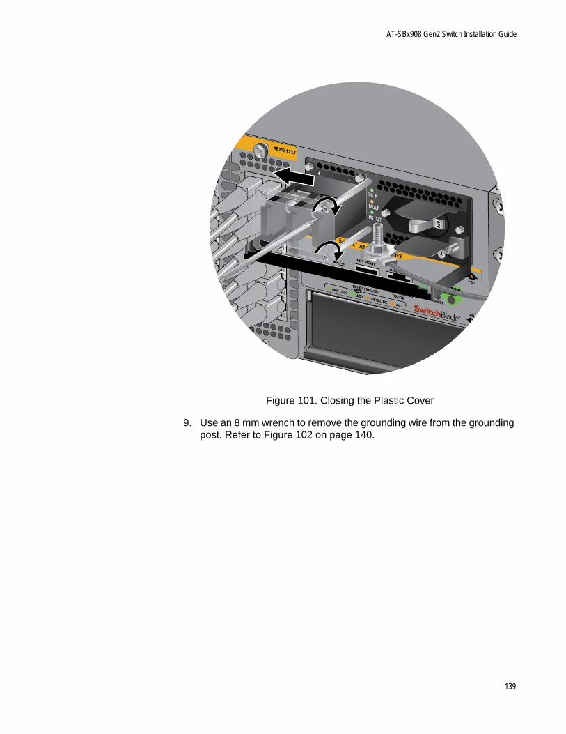
AT-SBx908 Gen2 Switch Installation Guide
Figure 101. Closing the Plastic Cover
9. Use an 8 mm wrench to remove the grounding wire from the grounding post. Refer to Figure 102 on page 140.
139
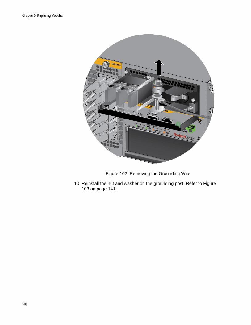
Chapter 6: Replacing Modules
Figure 102. Removing the Grounding Wire
10. Reinstall the nut and washer on the grounding post. Refer to Figure 103 on page 141.
140
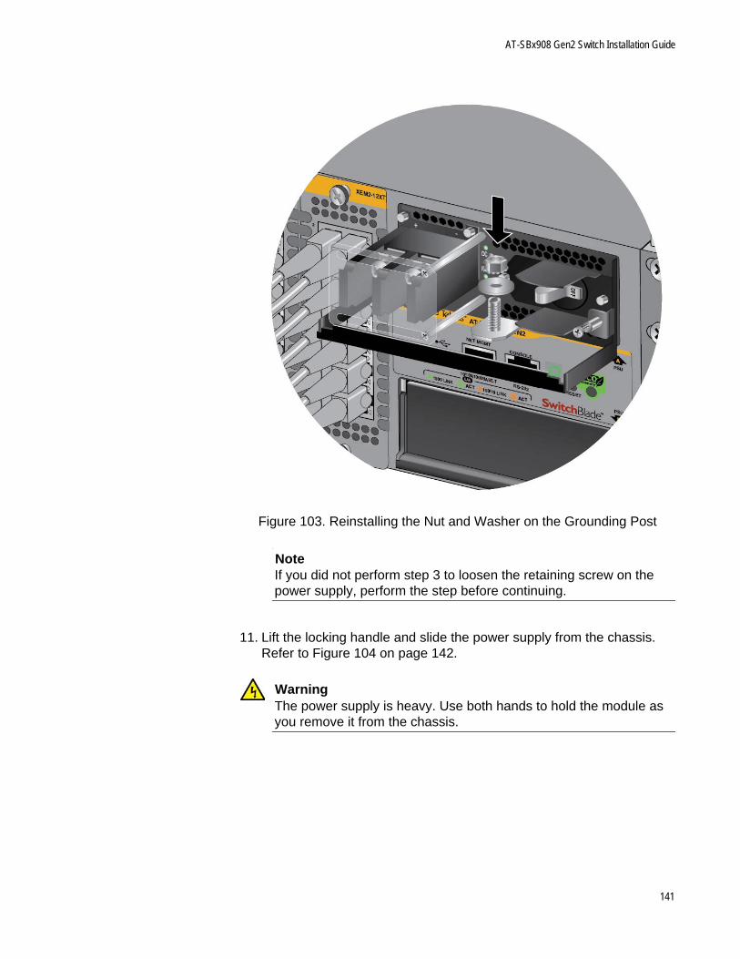
AT-SBx908 Gen2 Switch Installation Guide
Figure 103. Reinstalling the Nut and Washer on the Grounding Post
NoteIf you did not perform step 3 to loosen the retaining screw on the power supply, perform the step before continuing.
11. Lift the locking handle and slide the power supply from the chassis. Refer to Figure 104 on page 142.
WarningThe power supply is heavy. Use both hands to hold the module as you remove it from the chassis.
141
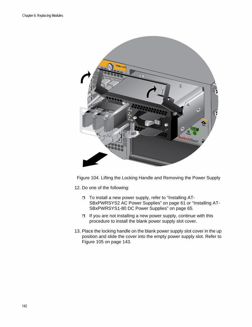
Chapter 6: Replacing Modules
Figure 104. Lifting the Locking Handle and Removing the Power Supply
12. Do one of the following:
To install a new power supply, refer to “Installing AT-SBxPWRSYS2 AC Power Supplies” on page 61 or “Installing AT-SBxPWRSYS1-80 DC Power Supplies” on page 65.
If you are not installing a new power supply, continue with this procedure to install the blank power supply slot cover.
13. Place the locking handle on the blank power supply slot cover in the up position and slide the cover into the empty power supply slot. Refer to Figure 105 on page 143.
142
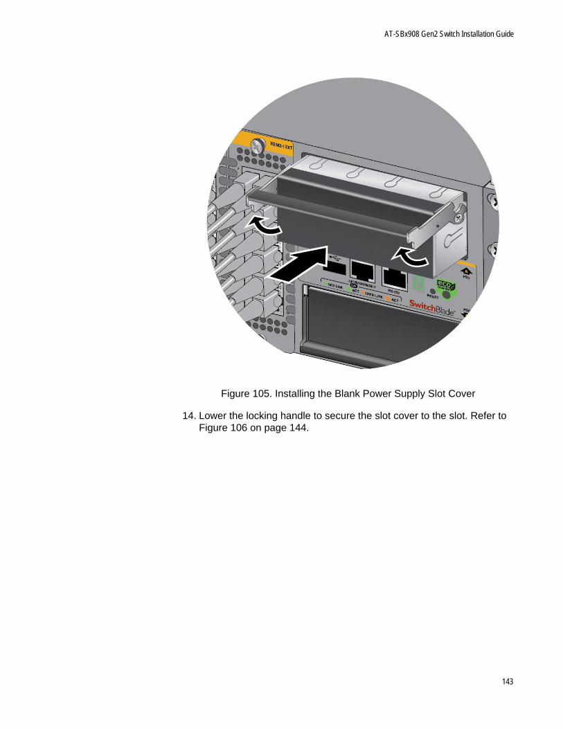
AT-SBx908 Gen2 Switch Installation Guide
Figure 105. Installing the Blank Power Supply Slot Cover
14. Lower the locking handle to secure the slot cover to the slot. Refer to Figure 106 on page 144.
143
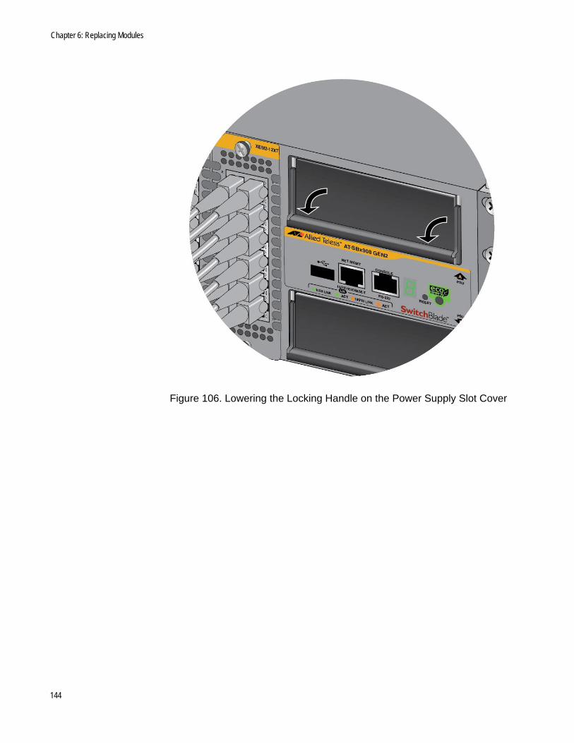
Chapter 6: Replacing Modules
Figure 106. Lowering the Locking Handle on the Power Supply Slot Cover
144

AT-SBx908 Gen2 Switch Installation Guide
Removing Ethernet Line Cards
This section contains the procedure for replacing Ethernet line cards in the AT-SBx908 Gen2 Chassis. The illustrations in the procedure show the AT-XEM2-12XT Line Card. The procedure is the same for all cards:
NoteAllied Telesis recommends saving a backup copy of the configuration file in the chassis before removing or replacing line cards. For instructions, refer to the Software Reference for SwitchBlade x908 Gen2 Switches.
The Ethernet line cards are hot-swappable. You do not have to power off the chassis to install or replace line cards.
This procedure requires the following tool:
#2 Phillips-head screwdriver (not provided)
To remove an Ethernet line card from the chassis, perform the following procedure:
1. Label and remove the cables from the Ethernet line card.
2. If the line card has fiber optic transceivers, install dust covers on the ports.
3. If the line card has transceivers, label and remove the transceivers.
4. Use a #2 Phillips-head screwdriver to loosen the two screws on the faceplate of the card. Refer to Figure 107 on page 146.
145
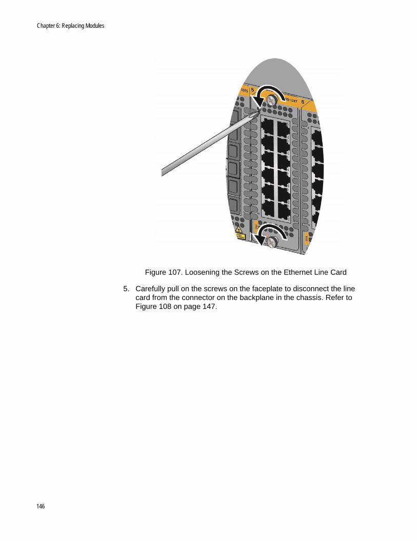
Chapter 6: Replacing Modules
Figure 107. Loosening the Screws on the Ethernet Line Card
5. Carefully pull on the screws on the faceplate to disconnect the line card from the connector on the backplane in the chassis. Refer to Figure 108 on page 147.
146
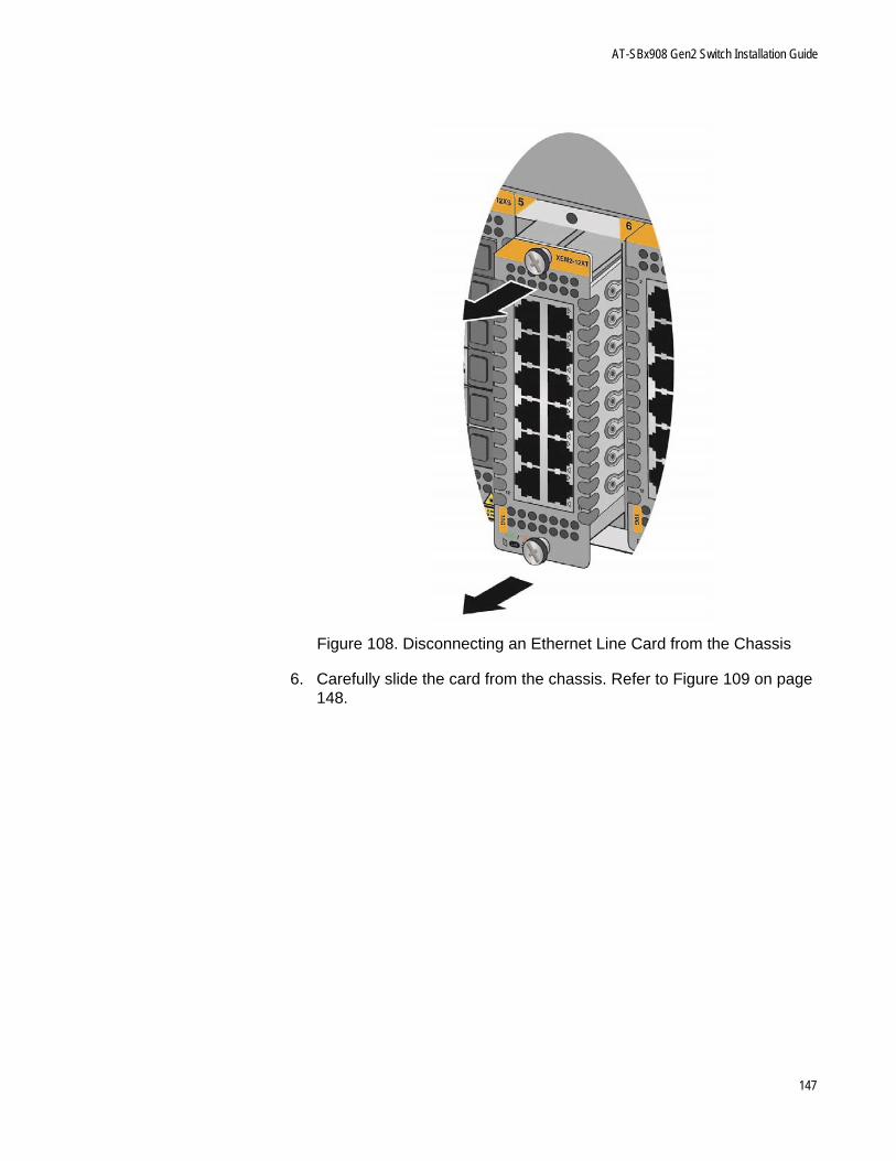
AT-SBx908 Gen2 Switch Installation Guide
Figure 108. Disconnecting an Ethernet Line Card from the Chassis
6. Carefully slide the card from the chassis. Refer to Figure 109 on page 148.
147
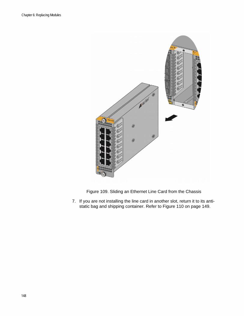
Chapter 6: Replacing Modules
Figure 109. Sliding an Ethernet Line Card from the Chassis
7. If you are not installing the line card in another slot, return it to its anti-static bag and shipping container. Refer to Figure 110 on page 149.
148
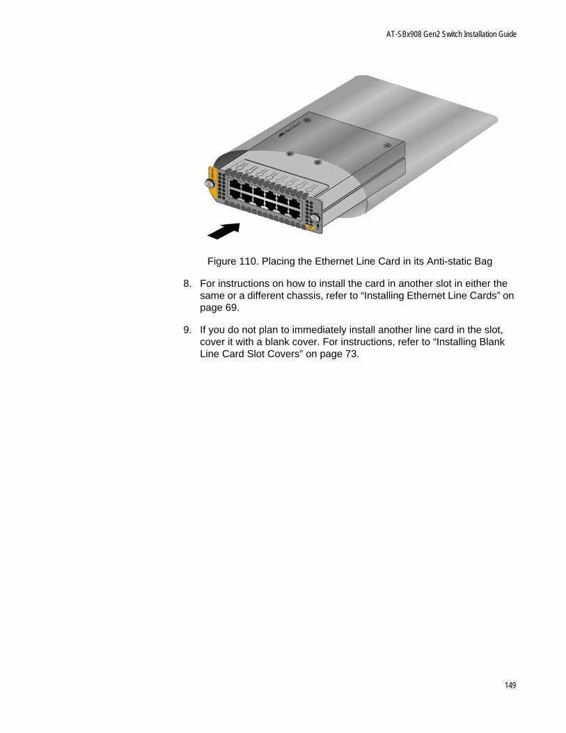
AT-SBx908 Gen2 Switch Installation Guide
Figure 110. Placing the Ethernet Line Card in its Anti-static Bag
8. For instructions on how to install the card in another slot in either the same or a different chassis, refer to “Installing Ethernet Line Cards” on page 69.
9. If you do not plan to immediately install another line card in the slot, cover it with a blank cover. For instructions, refer to “Installing Blank Line Card Slot Covers” on page 73.
149

Chapter 6: Replacing Modules
Replacing AT-FAN08 Modules
This section contains the procedure for replacing AT-FAN08 Modules in the AT-SBx908 Gen2 Chassis.
Removing AT-FAN08 Modules
This procedure requires the following tool:
#2 Phillips-head screwdriver (not provided)
The illustrations show the removal of the fan module from the Fan A slot on the back panel. The procedure is the same for removing the module from the Fan B slot.
To remove an AT-FAN08 Module from the chassis, perform the following procedure:
1. Use a #2 Phillips-head screwdriver to loosen the two screws on the faceplate of the fan module. Refer to Figure 111.
Figure 111. Loosening the Screws on the AT-FAN08 Module
2. Carefully pull on the screws on the faceplate to disconnect the line card from the connector on the backplane in the chassis. Refer to Figure 112 on page 151.
150
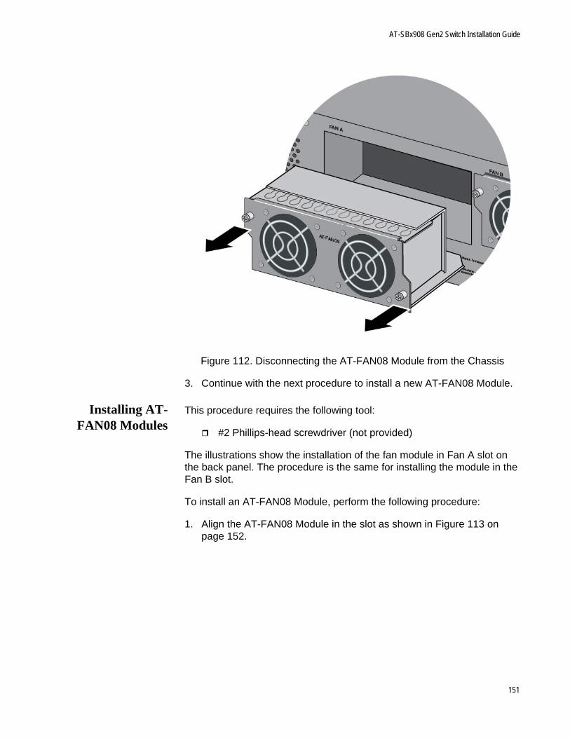
AT-SBx908 Gen2 Switch Installation Guide
Figure 112. Disconnecting the AT-FAN08 Module from the Chassis
3. Continue with the next procedure to install a new AT-FAN08 Module.
Installing AT-FAN08 Modules
This procedure requires the following tool:
#2 Phillips-head screwdriver (not provided)
The illustrations show the installation of the fan module in Fan A slot on the back panel. The procedure is the same for installing the module in the Fan B slot.
To install an AT-FAN08 Module, perform the following procedure:
1. Align the AT-FAN08 Module in the slot as shown in Figure 113 on page 152.
151
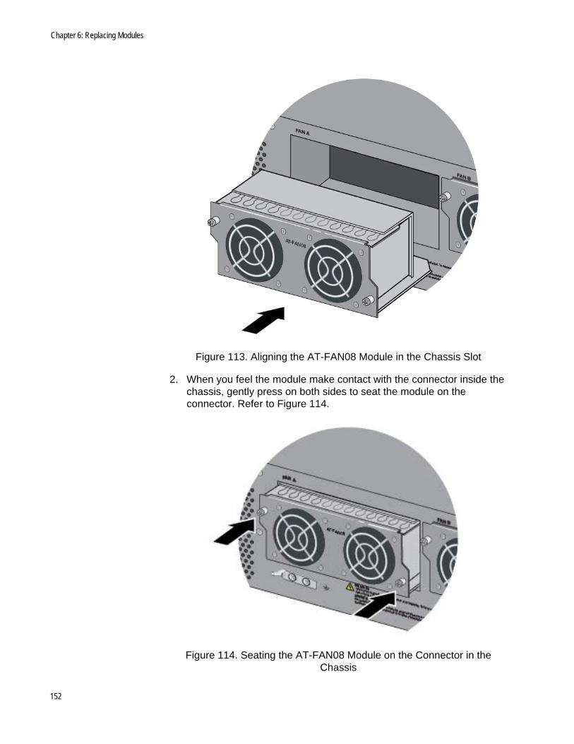
Chapter 6: Replacing Modules
Figure 113. Aligning the AT-FAN08 Module in the Chassis Slot
2. When you feel the module make contact with the connector inside the chassis, gently press on both sides to seat the module on the connector. Refer to Figure 114.
Figure 114. Seating the AT-FAN08 Module on the Connector in the Chassis
152
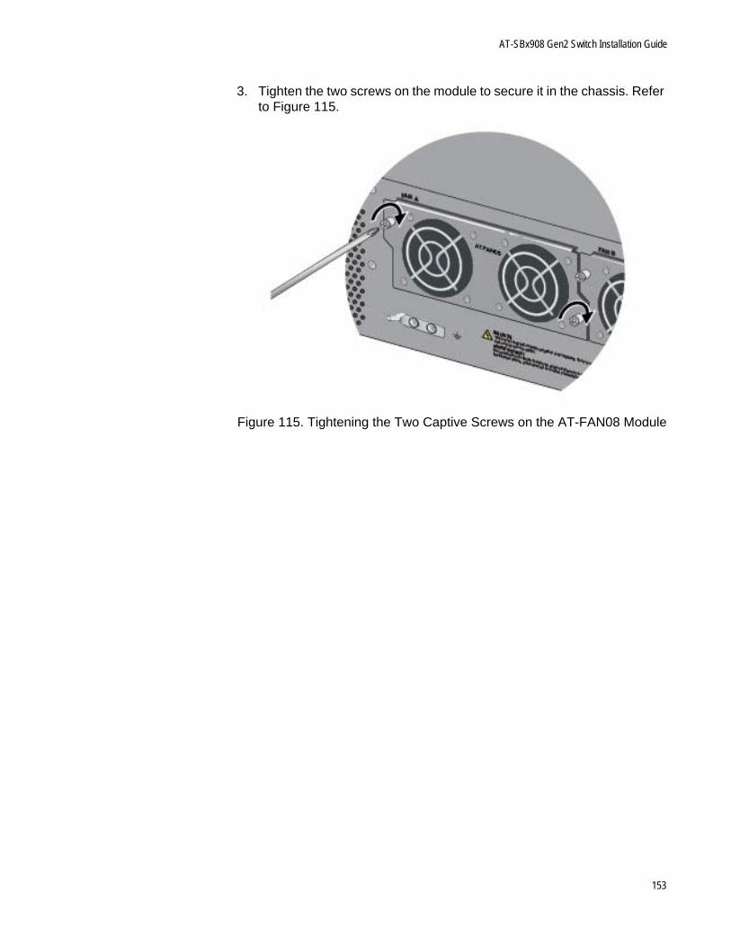
AT-SBx908 Gen2 Switch Installation Guide
3. Tighten the two screws on the module to secure it in the chassis. Refer to Figure 115.
Figure 115. Tightening the Two Captive Screws on the AT-FAN08 Module
153

Chapter 6: Replacing Modules
154
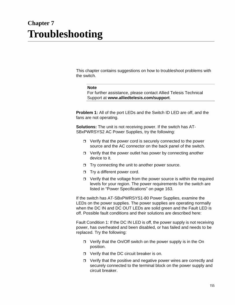
Chapter 7
Troubleshooting
This chapter contains suggestions on how to troubleshoot problems with the switch.
NoteFor further assistance, please contact Allied Telesis Technical Support at www.alliedtelesis.com/support.
Problem 1: All of the port LEDs and the Switch ID LED are off, and the fans are not operating.
Solutions: The unit is not receiving power. If the switch has AT-SBxPWRSYS2 AC Power Supplies, try the following:
Verify that the power cord is securely connected to the power source and the AC connector on the back panel of the switch.
Verify that the power outlet has power by connecting another device to it.
Try connecting the unit to another power source.
Try a different power cord.
Verify that the voltage from the power source is within the required levels for your region. The power requirements for the switch are listed in “Power Specifications” on page 163.
If the switch has AT-SBxPWRSYS1-80 Power Supplies, examine the LEDs on the power supplies. The power supplies are operating normally when the DC IN and DC OUT LEDs are solid green and the Fault LED is off. Possible fault conditions and their solutions are described here:
Fault Condition 1: If the DC IN LED is off, the power supply is not receiving power, has overheated and been disabled, or has failed and needs to be replaced. Try the following:
Verify that the On/Off switch on the power supply is in the On position.
Verify that the DC circuit breaker is on.
Verify that the positive and negative power wires are correctly and securely connected to the terminal block on the power supply and circuit breaker.
155
Chapter 7: Troubleshooting
Verify that the DC circuit break has power by attaching another device to it.
Verify that the power from the DC circuit break is within the required levels of the power supply. Refer to “Power Specifications” on page 349.
If the chassis is still operating, use the SHOW SYSTEM ENVIRONMENT command in the User Exec or Privileged Exec mode to determine if the power supply has overheated and shutdown. The Status column in the display provides the states of the chassis modules. Components that have an “Ok” status are operating normally.
Fault Condition 2: If the DC IN LED is solid green but the DC OUT LED is off, the power unit is generating insufficient DC power. Replace the power supply.
Fault Condition 3: If the Fault LED is solid amber, try the solutions in Fault Condition 1. If they do not resolve the problem, replace the power supply.
NoteThe power supply is hot swappable. If the chassis has two power supplies and one of them fails, you do not have to power off the operational power supply to replace the failed unit.
Problem 2: All of the port LEDs are off even though the ports are connected to active network devices.
Solution: The switch may be operating in the low power mode. To toggle on the LEDs, press the eco-friendly button on the front panel of the switch. You may also toggle the LEDs off and on with the ECOFRIENDLY LED and NO ECOFRIENDLY LED commands in the command line interface.
Problem 3: A 1GBase/10GBase twisted pair port on the AT-XEM2-12XT Ethernet Line Card is connected to a network device but the port’s LINK/ACT LED is off.
Solutions: The port is unable to establish a link to a network device. Try the following:
Verify that the network device connected to the twisted pair port is powered on and is operating properly.
Verify that the network device supports 1Gbps or 10Gbps operation. The AT-XEM2-12XT Card does not support 1Mbps or 10Mbps devices.
Try connecting another network device to the twisted pair port with a different cable. If the twisted pair port is able to establish a link, then the problem is with the cable or the other network device.
156
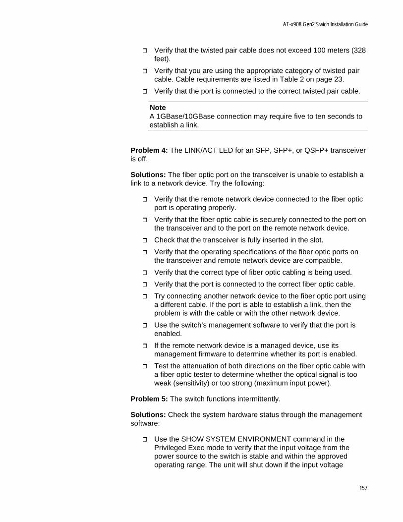
AT-x908 Gen2 Swich Installation Guide
Verify that the twisted pair cable does not exceed 100 meters (328 feet).
Verify that you are using the appropriate category of twisted pair cable. Cable requirements are listed in Table 2 on page 23.
Verify that the port is connected to the correct twisted pair cable.
NoteA 1GBase/10GBase connection may require five to ten seconds to establish a link.
Problem 4: The LINK/ACT LED for an SFP, SFP+, or QSFP+ transceiver is off.
Solutions: The fiber optic port on the transceiver is unable to establish a link to a network device. Try the following:
Verify that the remote network device connected to the fiber optic port is operating properly.
Verify that the fiber optic cable is securely connected to the port on the transceiver and to the port on the remote network device.
Check that the transceiver is fully inserted in the slot.
Verify that the operating specifications of the fiber optic ports on the transceiver and remote network device are compatible.
Verify that the correct type of fiber optic cabling is being used.
Verify that the port is connected to the correct fiber optic cable.
Try connecting another network device to the fiber optic port using a different cable. If the port is able to establish a link, then the problem is with the cable or with the other network device.
Use the switch’s management software to verify that the port is enabled.
If the remote network device is a managed device, use its management firmware to determine whether its port is enabled.
Test the attenuation of both directions on the fiber optic cable with a fiber optic tester to determine whether the optical signal is too weak (sensitivity) or too strong (maximum input power).
Problem 5: The switch functions intermittently.
Solutions: Check the system hardware status through the management software:
Use the SHOW SYSTEM ENVIRONMENT command in the Privileged Exec mode to verify that the input voltage from the power source to the switch is stable and within the approved operating range. The unit will shut down if the input voltage
157
Chapter 7: Troubleshooting
fluctuates above or below the approved operating range.
Use the SHOW SYSTEM ENVIRONMENT command in the Privileged Exec mode to verify that the fan is operating correctly.
Verify that the location of the switch allows for adequate airflow. The unit will shut down if it is overheating.
Problem 6: The Switch ID LED on the front of the switch is flashing the letter “F.”
Solutions: One or more of the following problems has occurred:
A cooling fan has failed.
The internal temperature of the switch has exceeded the normal operating range and the switch might have to shut down.
Contact your Allied Telesis sales representative for assistance.
158

Appendix A
Technical Specifications
This appendix contains the following sections:
”Physical Specifications” on page 160
”Environmental Specifications” on page 162
”Power Specifications” on page 163
”Certifications” on page 165
”Port Pinouts” on page 166
159
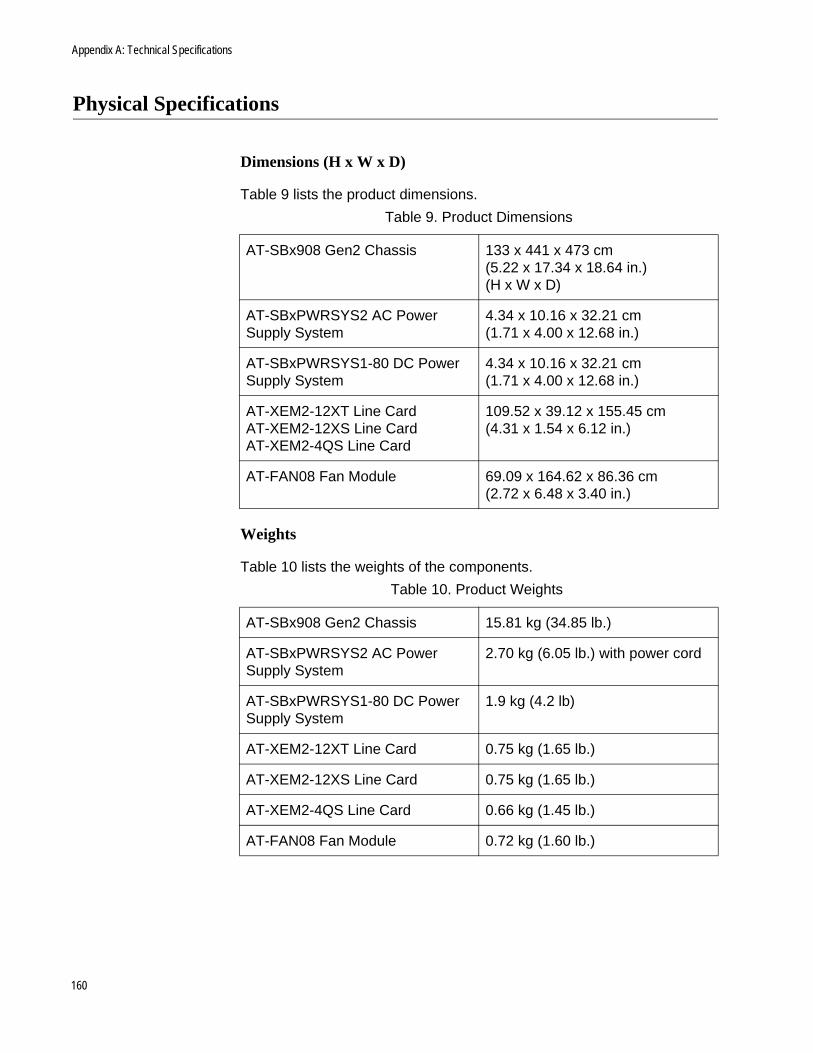
Appendix A: Technical Specifications
Physical Specifications
Dimensions (H x W x D)
Table 9 lists the product dimensions.
Weights
Table 10 lists the weights of the components.
Table 9. Product Dimensions
AT-SBx908 Gen2 Chassis 133 x 441 x 473 cm(5.22 x 17.34 x 18.64 in.)(H x W x D)
AT-SBxPWRSYS2 AC Power Supply System
4.34 x 10.16 x 32.21 cm(1.71 x 4.00 x 12.68 in.)
AT-SBxPWRSYS1-80 DC Power Supply System
4.34 x 10.16 x 32.21 cm(1.71 x 4.00 x 12.68 in.)
AT-XEM2-12XT Line CardAT-XEM2-12XS Line CardAT-XEM2-4QS Line Card
109.52 x 39.12 x 155.45 cm(4.31 x 1.54 x 6.12 in.)
AT-FAN08 Fan Module 69.09 x 164.62 x 86.36 cm(2.72 x 6.48 x 3.40 in.)
Table 10. Product Weights
AT-SBx908 Gen2 Chassis 15.81 kg (34.85 lb.)
AT-SBxPWRSYS2 AC Power Supply System
2.70 kg (6.05 lb.) with power cord
AT-SBxPWRSYS1-80 DC Power Supply System
1.9 kg (4.2 lb)
AT-XEM2-12XT Line Card 0.75 kg (1.65 lb.)
AT-XEM2-12XS Line Card 0.75 kg (1.65 lb.)
AT-XEM2-4QS Line Card 0.66 kg (1.45 lb.)
AT-FAN08 Fan Module 0.72 kg (1.60 lb.)
160

AT-SBx908 Gen2 Switch Installation Guide
Ventilation
Table 11 lists the ventilation requirements.
Table 11. Ventilation Requirements
Recommended Minimum Ventilation on All Sides
10 cm (4.0 in)
161

Appendix A: Technical Specifications
Environmental Specifications
Table 12 lists the environmental specifications of the switches.
Table 12. Environmental Specifications
Operating Temperature Range 0° C to 50° C (32° F to 122° F)
Storage Temperature Range -25° C to 70° C (-13° F to 158° F)
Operating Humidity Range 5% to 90% noncondensing
Storage Humidity Range 5% to 95% noncondensing
Maximum Operating Altitude 3,000 m (9,843 ft)
162
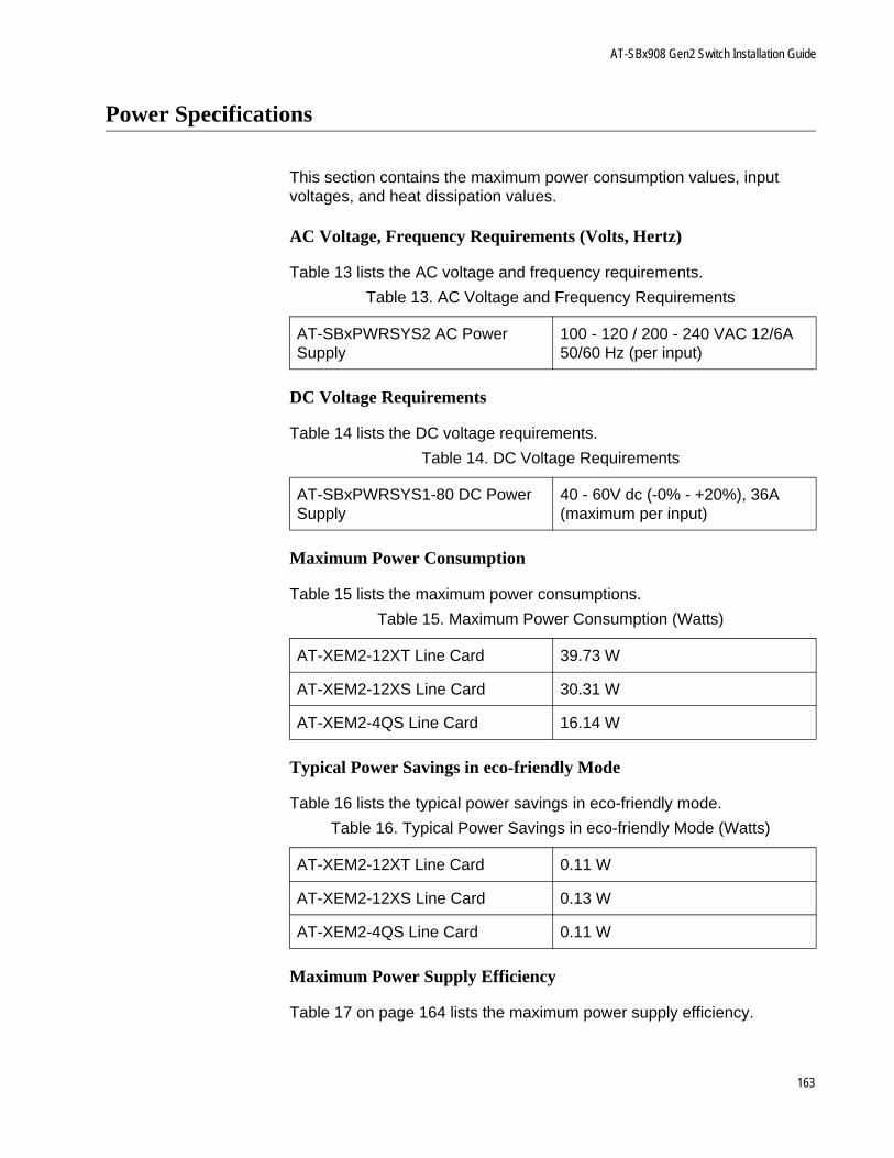
AT-SBx908 Gen2 Switch Installation Guide
Power Specifications
This section contains the maximum power consumption values, input voltages, and heat dissipation values.
AC Voltage, Frequency Requirements (Volts, Hertz)
Table 13 lists the AC voltage and frequency requirements.
DC Voltage Requirements
Table 14 lists the DC voltage requirements.
Maximum Power Consumption
Table 15 lists the maximum power consumptions.
Typical Power Savings in eco-friendly Mode
Table 16 lists the typical power savings in eco-friendly mode.
Maximum Power Supply Efficiency
Table 17 on page 164 lists the maximum power supply efficiency.
Table 13. AC Voltage and Frequency Requirements
AT-SBxPWRSYS2 AC Power Supply
100 - 120 / 200 - 240 VAC 12/6A 50/60 Hz (per input)
Table 14. DC Voltage Requirements
AT-SBxPWRSYS1-80 DC Power Supply
40 - 60V dc (-0% - +20%), 36A (maximum per input)
Table 15. Maximum Power Consumption (Watts)
AT-XEM2-12XT Line Card 39.73 W
AT-XEM2-12XS Line Card 30.31 W
AT-XEM2-4QS Line Card 16.14 W
Table 16. Typical Power Savings in eco-friendly Mode (Watts)
AT-XEM2-12XT Line Card 0.11 W
AT-XEM2-12XS Line Card 0.13 W
AT-XEM2-4QS Line Card 0.11 W
163
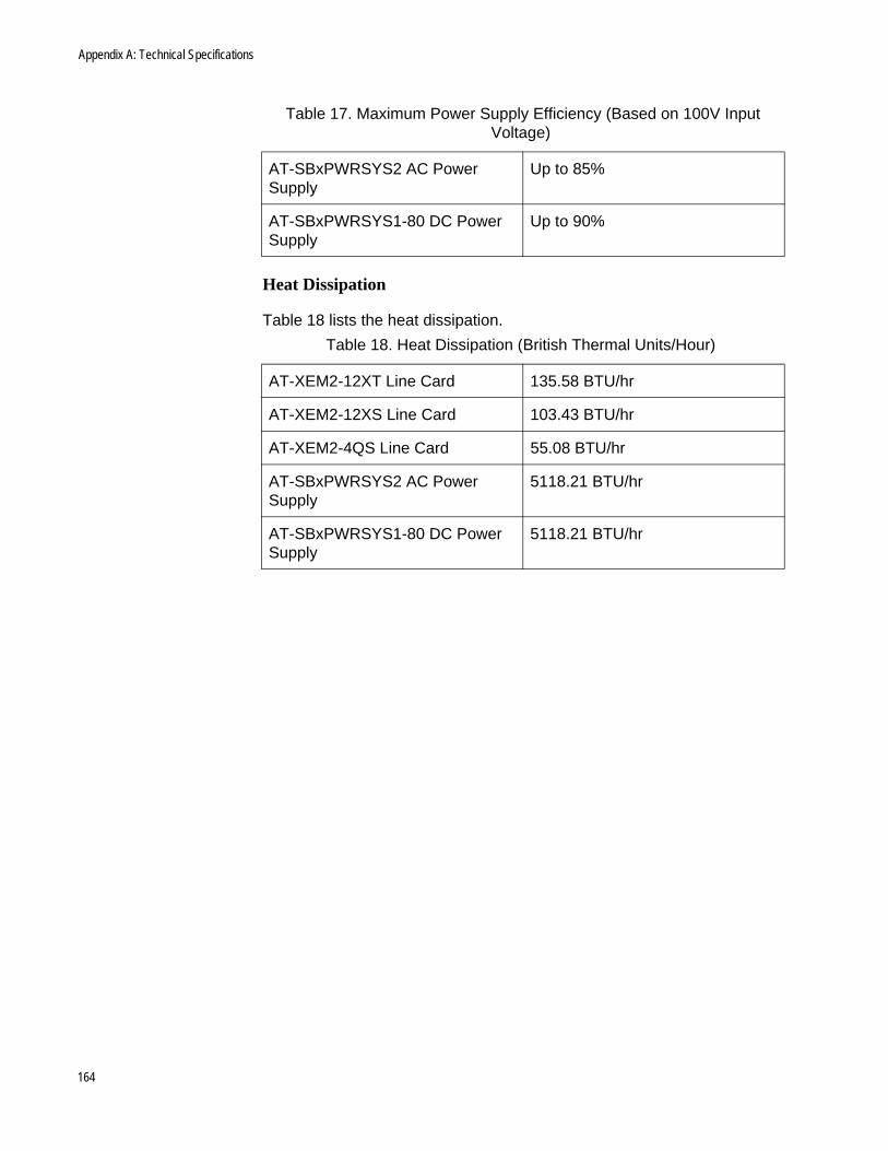
Appendix A: Technical Specifications
Heat Dissipation
Table 18 lists the heat dissipation.
Table 17. Maximum Power Supply Efficiency (Based on 100V Input Voltage)
AT-SBxPWRSYS2 AC Power Supply
Up to 85%
AT-SBxPWRSYS1-80 DC Power Supply
Up to 90%
Table 18. Heat Dissipation (British Thermal Units/Hour)
AT-XEM2-12XT Line Card 135.58 BTU/hr
AT-XEM2-12XS Line Card 103.43 BTU/hr
AT-XEM2-4QS Line Card 55.08 BTU/hr
AT-SBxPWRSYS2 AC Power Supply
5118.21 BTU/hr
AT-SBxPWRSYS1-80 DC Power Supply
5118.21 BTU/hr
164
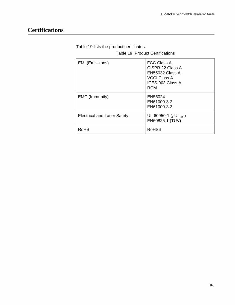
AT-SBx908 Gen2 Switch Installation Guide
Certifications
Table 19 lists the product certificates.
Table 19. Product Certifications
EMI (Emissions) FCC Class ACISPR 22 Class AEN55032 Class AVCCI Class AICES-003 Class ARCM
EMC (Immunity) EN55024EN61000-3-2EN61000-3-3
Electrical and Laser Safety UL 60950-1 (CULUS)EN60825-1 (TUV)
RoHS RoHS6
165
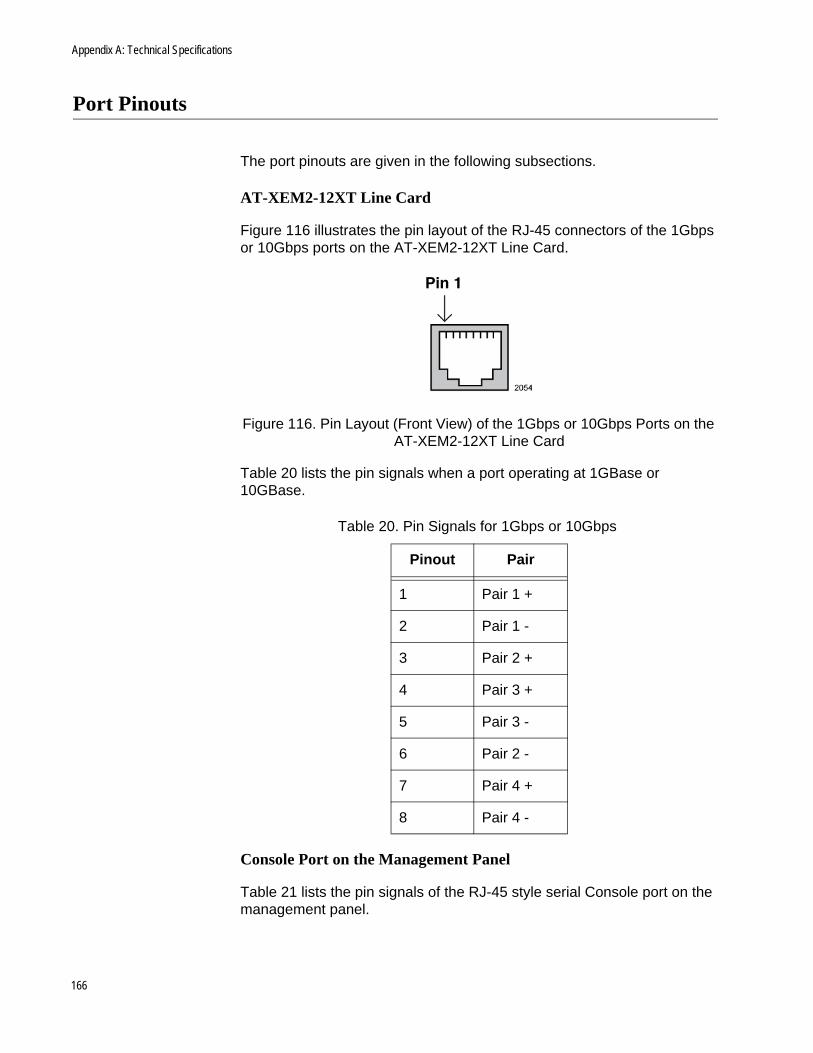
Appendix A: Technical Specifications
Port Pinouts
The port pinouts are given in the following subsections.
AT-XEM2-12XT Line Card
Figure 116 illustrates the pin layout of the RJ-45 connectors of the 1Gbps or 10Gbps ports on the AT-XEM2-12XT Line Card.
Figure 116. Pin Layout (Front View) of the 1Gbps or 10Gbps Ports on the AT-XEM2-12XT Line Card
Table 20 lists the pin signals when a port operating at 1GBase or 10GBase.
Console Port on the Management Panel
Table 21 lists the pin signals of the RJ-45 style serial Console port on the management panel.
Table 20. Pin Signals for 1Gbps or 10Gbps
Pinout Pair
1 Pair 1 +
2 Pair 1 -
3 Pair 2 +
4 Pair 3 +
5 Pair 3 -
6 Pair 2 -
7 Pair 4 +
8 Pair 4 -
166
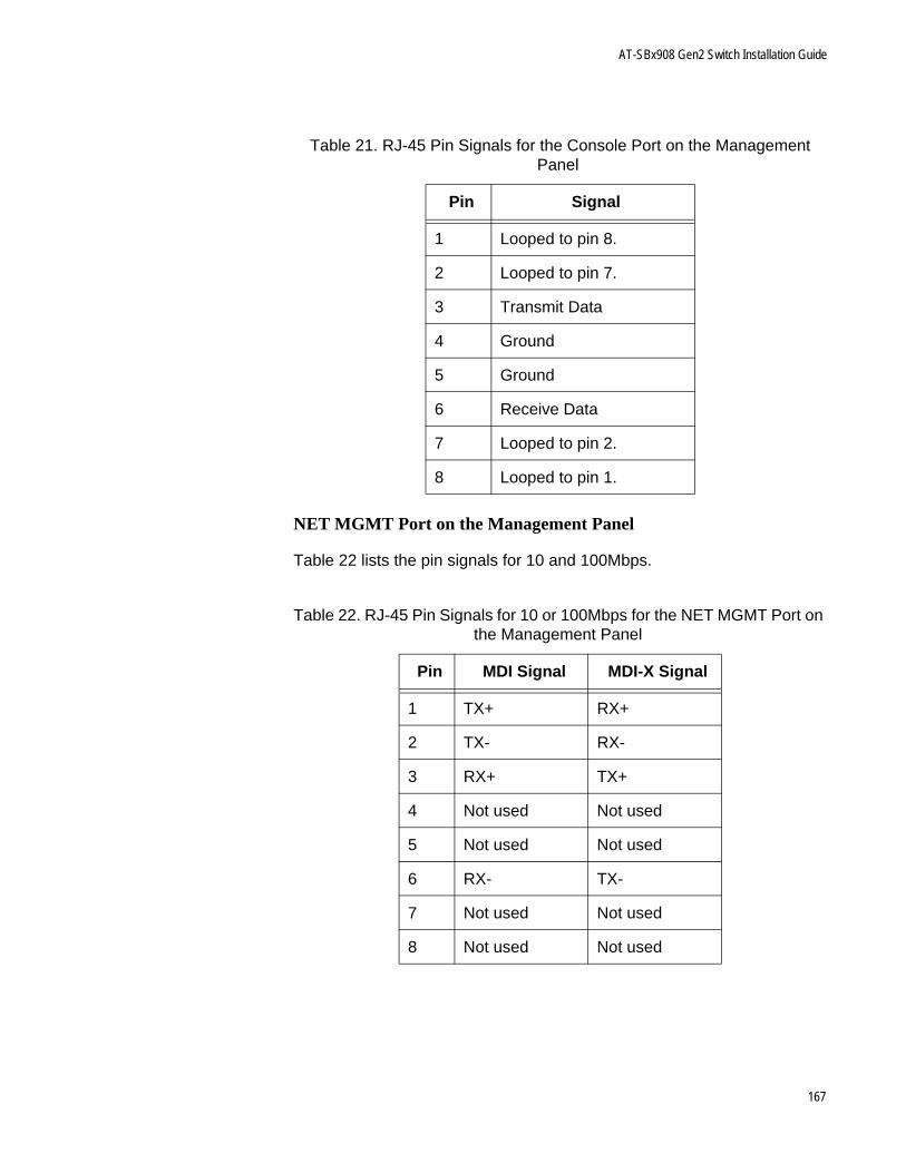
AT-SBx908 Gen2 Switch Installation Guide
NET MGMT Port on the Management Panel
Table 22 lists the pin signals for 10 and 100Mbps.
Table 21. RJ-45 Pin Signals for the Console Port on the Management Panel
Pin Signal
1 Looped to pin 8.
2 Looped to pin 7.
3 Transmit Data
4 Ground
5 Ground
6 Receive Data
7 Looped to pin 2.
8 Looped to pin 1.
Table 22. RJ-45 Pin Signals for 10 or 100Mbps for the NET MGMT Port on the Management Panel
Pin MDI Signal MDI-X Signal
1 TX+ RX+
2 TX- RX-
3 RX+ TX+
4 Not used Not used
5 Not used Not used
6 RX- TX-
7 Not used Not used
8 Not used Not used
167

Appendix A: Technical Specifications
168