asynchronous transfer mode (atm)jain/books/ftp/atm_chp.pdf · asynchronous transfer mode (atm)...
TRANSCRIPT

Asynchronous Transfer Mode (ATM)
Arjan Durresi
Department of Computer Science,
Louisiana State University,
Baton Rouge, LA 70803
Email: [email protected]
Raj Jain
Department of Computer Science and Engineering,
Washington University in St. Louis,
St. Louis, MO 63130
Email: [email protected]
Abstract
Asynchronous transfer mode (ATM) is a cell-oriented switching and multiplexing
technology that uses fixed-length (53 byte; 48 bytes of data, and 5 bytes of header
information) packets — called cells — to carry various types of traffic, such as data,
voice, video, multimedia, and so on, through multiple classes of services. ATM is a
1

connection-oriented technology, in which a connection is established between the two
endpoints before the actual data exchange begins.
ATM provides a highly complex technology, with features intended for applications
ranging from global telco networks to private local area computer networks. ATM has
been a partial success as a technology, with widespread deployment, but generally only
used as a transport for IP traffic; its goal of providing a single integrated end-to-end
technology for LANs, public networks, and user services has largely failed. However,
as it often happens in technology development, various important ATM concepts have
been inherited by other technologies, such as MPLS.
To accelerate the deployment of ATM technology, the ATM Forum, a consortium
of service providers and equipment vendors in the communication industries was cre-
ated to develop implementation and specification agreements. Later, ATM Forum was
merged with other industry forums to form MPLS Frame Relay ATM (MFA) forum
[23]. In this chapter, we present a brief overview on ATM protocol layers, the current
status on Traffic Management, and discuss related technologies such as MPLS, as well
as technologies using the ATM protocol layer stack, such as DSL, FTTP, and UMTS.
Keywords: Switching, traffic management, reference model, ATM.
2

Contents
1 Introduction 5
1.1 Basic Principles . . . . . . . . . . . . . . . . . . . . . . . . . . . . . . . . . . 5
1.2 The MFA Forum, ITU, and ANSI . . . . . . . . . . . . . . . . . . . . . . . 7
1.3 New Developments . . . . . . . . . . . . . . . . . . . . . . . . . . . . . . . . 8
2 ATM Protocol Reference Model 10
2.1 The ATM Adaptation Layer . . . . . . . . . . . . . . . . . . . . . . . . . . . 10
2.2 The ATM Layer . . . . . . . . . . . . . . . . . . . . . . . . . . . . . . . . . . 13
2.3 The Physical Layer . . . . . . . . . . . . . . . . . . . . . . . . . . . . . . . . 17
3 Traffic Management 18
3.1 Generic Functions . . . . . . . . . . . . . . . . . . . . . . . . . . . . . . . . . 19
3.2 Quality of Service Attributes . . . . . . . . . . . . . . . . . . . . . . . . . . . 22
3.3 Traffic Contract . . . . . . . . . . . . . . . . . . . . . . . . . . . . . . . . . . 23
3.4 Congestion Control Techniques . . . . . . . . . . . . . . . . . . . . . . . . . 26
4 Switch Architecture 30
4.1 Switch Interface . . . . . . . . . . . . . . . . . . . . . . . . . . . . . . . . . . 34
4.1.1 Input Modules . . . . . . . . . . . . . . . . . . . . . . . . . . . . . . 34
3

4.1.2 Output Modules . . . . . . . . . . . . . . . . . . . . . . . . . . . . . 35
4.2 Connection Admission Control (CAC) . . . . . . . . . . . . . . . . . . . . . 35
4.3 Switch Management . . . . . . . . . . . . . . . . . . . . . . . . . . . . . . . 36
4.4 The Cell Switch Fabric . . . . . . . . . . . . . . . . . . . . . . . . . . . . . . 38
4.4.1 Concentration, Expansion, and Multiplexing . . . . . . . . . . . . . . 38
4.4.2 Routing and Buffering . . . . . . . . . . . . . . . . . . . . . . . . . . 39
4.5 Switch Design Principles . . . . . . . . . . . . . . . . . . . . . . . . . . . . . 47
4.5.1 Internal Blocking . . . . . . . . . . . . . . . . . . . . . . . . . . . . . 47
4.5.2 Buffering Approaches . . . . . . . . . . . . . . . . . . . . . . . . . . . 47
4.6 Buffer Sharing . . . . . . . . . . . . . . . . . . . . . . . . . . . . . . . . . . . 50
5 New Developments 51
5.1 Multiprotocol label switching - (MPLS) . . . . . . . . . . . . . . . . . . . . . 51
5.2 Technologies exploiting ATM and AAL layers . . . . . . . . . . . . . . . . . 53
6 Conclusion 56
7 GLOSSARY 57
4

1 Introduction
The purpose of this chapter is to introduce the reader to the basic aspects of asynchronous
transfer mode (ATM) networks. The length of this short chapter makes it impossible to
cover all important aspects of ATM networks. Much of the material in this chapter is based
on existing tutorials on ATM, including [4, 3, 8, 12, 14, 23, 17, 51, 64, 58, 42, 37]. The
industrial momentum behind ATM technology and the intensive research interest in ATM
has led to a vast and diversified literature in recent years. Most of the cited references are
mainly review articles or documents of ATM and MFA Forums [23]. Interested readers in
further understanding of the individual topics are referred to the corresponding papers and
the references therein.
1.1 Basic Principles
Various network applications are requiring increasingly higher bandwidth and generating
a heterogeneous mix of network traffic. Existing networks cannot provide the transport
facilities to efficiently support a diversity of traffic with various service requirements. ATM
was designed to be potentially capable of supporting heterogeneous traffic (e.g., voice, video,
data) in one transmission and switching fabric technology. It promised to provide greater
integration of capabilities and services, more flexible access to the network, and more efficient
and economical service.
ATM is a switching and multiplexing technology that employs small, fixed-length packets
(called cells). Each cell has 5 bytes of header information and a 48-byte information field
5

(payload). The reason for choosing a fixed-size packet was to ensure that the switching and
multiplexing function could be carried out quickly, easily, and with least delay variation.
The reason for choosing a small size cell was mainly a result of the need to support delay-
intolerant interactive voice service (e.g., phone calls) with a a small packetization delay, i.e.,
the time needed to fill a cell with PCM (pulse code modulation) encoded voice samples
arriving at the rate of 64 Kbps.
ATM is a connection-oriented technology in the sense that before two systems on the network
can communicate, they should inform all intermediate switches about their service require-
ments and traffic parameters. This is similar to the telephone networks where a fixed path
is set up from the calling party to the receiving party. In ATM networks, each connection is
called a virtual circuit or virtual channel (VC), because it also allows the capacity of each
link to be shared by connections using that link on a demand basis rather than by fixed
allocations. The connections allow the network to guarantee the quality of service (QoS)
by limiting the number of VCs. Typically, a user declares key service requirements at the
time of connection setup, declares the traffic parameters, and may agree to control these
parameters dynamically as demanded by the network.
ATM was intended to provide a single unified networking standard that could support both
synchronous and asynchronous technologies and services, while offering multiple levels of
quality of service for packet traffic.
ATM sought to resolve the conflict between circuit-switched networks and packet-switched
networks by mapping both bit streams and packet streams onto a stream of small fixed-size
6

“cells” tagged with virtual circuit identifiers. Cells are typically sent on demand within a
synchronous time slot pattern in a synchronous bit stream: what is asynchronous here is the
sending of the cells, not the low-level bitstream that carries them.
In its original conception, ATM was to be the enabling technology of the “broadband in-
tegrated services digital network” (B-ISDN) that would replace the existing narrowband
“integrated services digital network (ISDN). The full suite of ATM standards provides defi-
nitions for layer 1 (physical connections), layer 2 (data link layer), and layer 3 (network) of
the classical OSI seven-layer networking model. Because ATM is asynchronous, it provides
true bandwidth-on-demand. Additionally, ATM is capable of handling any form of informa-
tion (e.g., data, voice, video, audio, e-mail, faxes), moving this information quickly across a
network with millions of virtual paths and channels between end-user equipment
ATM allows the user to select the required level of service, provides guaranteed service
quality, and makes reservations and preplans routes so those transmissions needing the most
attention are given the best service.
1.2 The MFA Forum, ITU, and ANSI
With the objective of accelerating the convergence of standards and industry cooperation,
an international consortium called the ATM Forum was founded to ensure interoperability
between public and private ATM implementations and to promote the use of ATM products
and services. Although it was not a standard body, the ATM Forum worked closely with
standard organizations such as the International Telecommunications Union (ITU) and Inter-
7

net Engineering Task Force (IETF) in developing the definitions for ATM standards. In 2005
the ATM Forum was merged in MPLS Frame Relay and ATM Forum — MFA Forum, which
is an international, industry-wide, nonprofit association of telecommunications, networking,
and other companies focused on advancing the deployment of multi-vendor, multi-service
packet-based networks, associated applications, and interworking solutions [23].
The ITU is rooted in the International Telegraphy Union, founded in Paris in 1865. Its
name changed in 1934, and in 1947 the ITU became an agency of the United Nations.
The ITU works with public and private organizations to develop earth-linked and satellite
communications, while developing standards for all types of telecommunication technology.
The ITU-Telecommunication Standardization Sector (ITU-T) is the leader in defining in-
tegrated services digital network (ISDN), B-ISDN, and ATM specifications. The American
National Standards Institute (ANSI) is the formal standards body guiding the development
of ATM in the UStates.
1.3 New Developments
Numerous telcos have implemented wide-area ATM networks, and many ADSL implementa-
tions use ATM. However, ATM has failed to gain wide use as a LAN technology, and its great
complexity has held back its full deployment as the single integrating network technology in
the way that its inventors originally intended.
Many people, particularly in the Internet protocol-design community, considered this vision
to be mistaken. Although there is a need for a unifying protocol at network layer, to be
8

able to run over all existing and future link-layer technologies, ATM could not do this role.
Conveniently, IP already plays the role of such an integrator in a more scalable, more flexible,
less complex, and most importantly, less expensive way than ATM could do. Therefore, there
was no point in implementing ATM as an integrator at the network layer.
In addition, the need for cells to reduce jitter has disappeared as transport speeds increased
(see below), and improvements in voice over IP have made the integration of speech and
data possible at the IP layer, again removing the incentive for ubiquitous deployment of
ATM. Most telcos are now planning to integrate their voice network activities into their IP
networks, rather than their IP networks into the voice infrastructure.
Many technically sound ideas from ATM were adopted by MPLS, a generic layer 2 packet
switching protocol. ATM remains widely deployed, and is used as a multiplexing service
in DSL networks, where its compromises fit DSL’s low-data-rate needs well. In turn, DSL
networks support IP (and IP services such as VoIP) via PPP over ATM.
ATM will remain deployed for some time in higher-speed interconnects where carriers have
already committed themselves to existing ATM deployments; ATM is used here as a way of
unifying PDH/SDH traffic and packet-switched traffic under a single infrastructure.
However, ATM is increasingly challenged by speed and traffic shaping requirements of con-
verged networks. In particular, the complexity of SAR imposes a performance bottleneck,
as the fastest SARs known run at 2.5 Gbps and have limited traffic shaping capabilities.
Currently it seems like Ethernet implementations (10-Gbit-Ethernet [18], Metro Ethernet
[20]) will replace ATM in many locations.
9

2 ATM Protocol Reference Model
The ATM protocol reference model is based on standards developed by the ITU. Communi-
cation from higher layers is adapted to the lower ATM defined layers, which in turn pass the
information onto the physical layer for transmission over a selected physical medium. The
protocol reference model is divided into three layers: the ATM adaptation layer (AAL), the
ATM layer, and the physical layer, as shown in Figure 1 [4]. The three management planes
user/control plane, layer management and plane management, are shown in Figure 2 [4].
Figure 1: ATM protocol structure
2.1 The ATM Adaptation Layer
The ATM adaptation layer (AAL) interfaces the higher layer protocols to the ATM Layer.
It relays ATM cells both from the upper layers to the ATM layer and vice versa. When
relaying information received from the higher layers to the ATM layer, the AAL segments
10

Figure 2: ATM model
the data into ATM cells. When relaying information received from the ATM Layer to the
higher layers, the AAL must take the cells and reassemble the payloads into a format that
the higher layers can understand. This is called segmentation and reassembly (SAR).
Four types of AALs were proposed, each supporting a different type of traffic or service
expected to be used on ATM networks. The service classes and the corresponding types of
AALs are as follows:
• AAL0 AAL0 payload consists of 48 bytes without special field, is also referred to as
raw cells.
• AAL1 AAL1 was designed to support constant bit rate applications. Examples of these
types of applications include 64 Kbps voice, fixed-rate uncompressed video, and leased
lines for private data networks.
• AAL2: AAL2 was initially conceived to support variable bit rate applications that
require a bounded delay for delivery. One example of such applications is compressed
11

packetized voice or video. The requirement on bounded delay for delivery is necessary
for the receiver to reconstruct the original uncompressed voice or video. Although,
AAL2 was conceived in early years of ATM development, it was not designed. So later
when ATM designers needed an AAL for voice traffic, they first labeled it AAL6 and
then quickly relabeled it as AAL2. So today, AAL2 is used for carrying voice traffic
and allows several small compressed voice packets to be packed in a single 48-byte cell
payload.
• AAL3/4: AAL3 and AAL4 were conceived for connection-oriented and connectionless
data traffic that do not have delay constraints. Both these were to support variable bit
rate data applications such as file transfer. However, designers quickly realized that
there was little difference between the two types of traffic and so a single AAL called
AAL 3/4 was designed. Because of the high complexity of AAL3/4 protocols, a simpler
AAL called AAL5 was later proposed and is the common AAL used today. AAL 3/4
is no longer used.
• AAL5: AAL5 is designed for data traffic that do not have delay constraints. Examples
of applications include IP traffic, LAN, FTP, and network management.
Although each AAL is optimized for a specific type of traffic, there is no stipulation in the
standards that AALs designed for one class of traffic cannot be used for another. In fact,
many vendors of ATM equipment currently manufacture products that use AAL5 to support
all the above classes of traffic, and most activities at the ATM Forum were focused on AAL5.
The AAL5 is also important in the internetworking of different networks and services. For
12

more discussion on the issues in AAL5 design, see [63]. AAL1 is also important, because it
is used for streams and for circuit emulation [1].
AAL5 places control information in an 8-octet trailer at the end of the packet. The AAL5
trailer contains a 16-bit length field, a 32-bit cyclic redundancy check (CRC) and two 8-bit
fields labeled UU and CPI that are currently unused.
In AAL5, each higher layer packet is divided into an integral number of ATM cells. At the
receiving end, these cells are reassembled into a packet before delivery to the receiving host.
The last cell contains padding to ensure that the entire AAL5 protocol data unit (PDU) is
a multiple of 48 octets long. The final cell contains up to 40 octets of data, followed by zero
padding and the 8-octet trailer.
2.2 The ATM Layer
The ATM layer provides an interface between the AAL and the physical layer. This layer is
responsible for relaying cells from the AAL to the physical layer for transmission and from
the physical layer to the AAL for use at the end systems. When it is inside an end system,
the ATM layer receives a stream of cells from the physical layer and transmits cells with new
data. When it is inside a switch, the ATM layer determines where the incoming cells should
be forwarded to, modifies the corresponding connection identifiers, and forwards the cells to
the next link. Moreover, it buffers incoming and outgoing cells, and handles various traffic
management functions such as cell loss priority marking, congestion indication, and generic
flow control. It also monitors the transmission rate and conformance to the service contract
13

(traffic policing). Traffic management was a hotly debated topic in the ATM Forum, and we
shall address the important issues in more details later.
The fields in the ATM cell header define the functionality of the ATM layer. The format of
the header for ATM cells has two different forms, one for use at the user-to-network interface
(UNI) [10, 9] and the other for use internal to the network, the network-to-node interface
(NNI), as shown in Figure 3. ATM user network interface (UNI) signalling specification
version 4.1 [10, 9] was standardized in 2002. At the UNI, the header dedicates four bits to
a function called generic flow control (GFC), which was originally designed to control the
amount of traffic entering the network. This allows the UNI to limit the amount of data
entering the network during periods of congestion. At the NNI, these four bits are allocated
to the virtual path identifier (VPI).
The ATM inter network interface (AINI) protocol [5] was designed for use between ATM
networks. AINI protocol is based on ATM Forum PNNI signalling [25]. The networks
on either side of the AINI may be running any protocol internally. However, the goal in
defining this protocol was to facilitate interworking of two networks running PNNI internally
in disjoint PNNI routing domains.
Figure 4 gives an illustration of ATM Network Interfaces.
The VPI and the virtual channel identifier (VCI) together, as shown in Figure 5, form the
routing field, which associates each cell with a particular channel or circuit, see Figure 6.
Each VCI identifies a single flow (channel); the VPI allows grouping of VCs with different
VCIs that can be switched together as an entity. However, the VPIs and VCIs have signif-
14

Figure 3: UNI (left) and NNI (right) ATM cell format
Figure 4: ATM network interfaces
icance only on the local link; the contents of the routing field will generally change as the
cell traverses from link to link. For the UNI, the routing field contains 24 bits and thus the
interface can support over 16 million concurrent sessions. At the NNI, the field contains 28
bits, allowing for over 268 million sessions to share a link within a subnet. We refer the
readers to the discussion of important issues in private network-to-network interface (PNNI)
routing to [25, 49].
The payload type indicator (PTI) field is used to distinguish between cells carrying user
data and cells containing control information. This allows control and signaling data to
be transmitted on a different subchannel from user data and hence separation of user and
control data. A particular bit is used by the AAL if the cell is a part of an AAL5 connection.
15

Figure 5: Virtual path and virtual channels
Figure 6: VP and VC switching
Another bit is used to indicate that the cell has experienced congestion.
The cell loss priority (CLP) bit provides the network with a selective discard capability
within each VPI/VCI. Cells with a CLP bit setting of 1 are discarded before cells with a
CLP bit setting of 0. This bit could be set by a user to indicate lower-priority cells that
16

could be discarded by the network during periods of congestion. Whereas data applications
generally cannot suffer any cell loss without the need for retransmission, voice and video
traffic, especially if not compressed, can tolerate minor cell loss. One could, therefore, code
voice and video traffic such that some less important cells could be marked with CLP = 1
while other more important cells would be marked with CLP = 0. The CLP bit could also
be used by the network to indicate cells that exceed the negotiated rate limit of a user.
The header error check (HEC) field is used to reduce errors in the header that cause a
misrouting of the cell for one user into another user’s data stream. This field contains the
result of an 8-bit CRC checking on the ATM header (this does not include the payload).
When a switch or an end system terminates the header, multiple-bit errors will be detected
with a high probability. Moreover, a single-bit error can be corrected. This is desirable
since ATM is intended for use on fiber optics link, where the error rate is less than 10−9
with current modulation techniques. Therefore, single-bit error correction is quite effective
in removing most header errors.
2.3 The Physical Layer
The physical layer defines the bit timing and other characteristics for encoding and decoding
the data into suitable electrical/optical waveforms for transmission and reception on the
specific physical media used. In addition, it also provides cell delineation function, header
error check (HEC) generation and processing, performance monitoring, and payload rate
matching of the different transport formats used at this layer.
17

The Synchronous Optical Network (SONET), a synchronous transmission structure, is often
used for framing and synchronization at the physical layer. In addition to the optical media
and line rates defined for SONET, the ATM Forum has proposed a variety of physical layer
standards, such as ATM over twisted-pair wire. This will accelerate the acceptance of ATM
as a desktop connection technology since existing cabling plants can be retained and the cost
per connection will be reduced. We refer the readers to [54] for a discussion on the ATM
physical layer issues.
3 Traffic Management
In order for ATM networks to deliver guaranteed quality of service (QoS) on demand while
maximizing the utilization of available network resources, effective traffic management mech-
anisms are needed. Almost every aspect of ATM network operation, from signaling requests
and routing to network resource allocation and policing, contains some traffic management
mechanisms [26].
A set of six service categories are specified. For each one, a set of parameters is given to
describe both the traffic presented to the network, and the QoS which is required of the
network.
18

3.1 Generic Functions
To meet the QoS objectives, the following functions [26] form a framework for managing
and controlling traffic and congestion in ATM networks and may be used in appropriate
combinations depending on the service category.
• Network Resource Management: is used in broadband networks to keep track of
the way link resources are allocated to connections. The two primary resources that
are tracked by network resource management are capacity (bandwidth) and connection
identifiers. Network resource management keeps track of the capacity and controls the
allocation of capacity to connections when requested as part of the connection setup
process [60]. In ATM, the service architecture allows logical separation of connections
according to service characteristics. Although cell scheduling and resource provisioning
are implementation and network specific, they can be utilized to provide appropriate
isolation and access to resources. Virtual paths are a useful tool for resource manage-
ment.
• Traffic policing: is monitoring network traffic for conformity with a traffic contract.
An application that wishes to use the broadband network to transport traffic must first
request a connection, which involves informing the network about the characteristics
of the traffic and the quality of service (QOS) required by the application [39]. This
information is stored in a traffic contract. If the connection request is accepted, the
application is permitted to use the network to transport traffic.
The main purpose of this function is to protect the network resources from malicious
19
connections and to enforce the compliance of every connection to its negotiated traffic
contract. The network also has the capability to discard non-conformant traffic in the
network (using priority control). Traffic policing in ATM networks is known as usage
parameter control (UPC) and network parameter control (NPC) [59].
• Traffic shaping provides a mechanism to control the volume of traffic being sent into
a network (bandwidth throttling), and the rate at which the traffic is being sent (rate
limiting). For this reason, traffic shaping schemes are commonly implemented at the
network edges to control traffic entering the network. The objectives of this function
are to achieve a better network efficiency while meeting the QoS objectives and/or to
ensure connection traffic conformance at a subsequent interface. Simple traffic shaping
schemes like leaky bucket and token bucket rely on shaping all traffic uniformly by
rate.
• Connection admission control (CAC): Admission control is the simple prac-
tice of discriminating which traffic is admitted into a network in the first place [39].
Admission control in ATM networks is known as connection admission control (CAC)
[59].
Connection admission control is defined as the set of actions taken by the network
during the call set-up phase in order to determine whether a connection request can
be accepted or should be rejected (or whether a request for re-allocation can be ac-
commodated).
• Feedback controls: are defined as the set of actions taken by the network and by
20

end-systems to regulate the traffic submitted on ATM connections according to the
state of network elements. This specification defines one network feedback control
mechanism: the ABR flow control. The ABR flow control may be used to adaptively
share the available bandwidth among participating users.
• Usage parameter control (UPC): is defined as the set of actions taken by the
network to monitor traffic and enforce the traffic contract at the user network. Network
parameter control (NPC) is a similarly defined set of actions at the Network Node
Interface. The main purpose of UPC and NPC is to protect network resources from
malicious as well as unintentional misbehavior, which can affect the QoS of other
already established connections, by detecting violations of negotiated parameters and
taking appropriate actions. Such actions may include cell discard and cell tagging.
• Cell loss priority control: For some service categories the end system may generate
traffic flows of cells with cell loss priority (CLP) marking. The network may follow
models which treat this marking as transparent or as significant. If treated as signifi-
cant, the network may selectively discard cells marked with a low priority to protect,
as far as possible, the QoS objectives of cells with high priority.
• Frame discard: A congested network that needs to discard cells may discard at the
frame level rather than at the cell level.
21
3.2 Quality of Service Attributes
While setting up a connection on ATM networks, users can negotiate with the network the
following parameters related to the desired quality of service:
• Peak-to-peak cell delay variation (peak-to-peak CDV).
Cell transfer delay (CTD) is the delay experienced by a cell between network entry and
exit points is called the cell transfer delay. It includes propagation delays, queueing
delays at various intermediate switches, and service times at queueing points.
The peak-to-peak CDV is the difference between the (1− α) quantile of the CTD and
the fixed CTD that could be experienced by any delivered cell on a connection during
the entire connection holding time. The term peak-to-peak refers to the difference
between the best and worst case of CTD, where the best case is equal to the fixed
delay, and the worst case is equal to a value likely to be exceeded with probability no
greater than α.
• Maximum cell transfer delay (maxCTD).
Cell delay variation (CDV) is a measure of variance of CTD. High variation implies
larger buffering for delay sensitive traffic such as voice and video.
The maximum cell transfer delay (maxCTD) specified for a connection is the (1 − α)
quantile of CTD. The CLR at connection request time is used to place an upper bound
on α.
• Cell loss ratio (CLR): The percentage of cells that are lost in the network because of
22

error or congestion and are not delivered to the destination, i.e.,
CLR =# Lost Cells
# Transmitted Cells.
Recall that each ATM cell has a cell loss priority (CLP) bit in the header. During
periods of congestion, the network will first discard cells with CLP = 1. Because the
loss of cells with CLP = 0 is more harmful to the operation of the application, CLR
can be specified separately for cells with CLP = 1 and for those with CLP = 0.
All these parameters are described in details in the ”Traffic Management Specification”
document [26].
3.3 Traffic Contract
To provide a guaranteed QoS, a traffic contract is established during connection setup,
which contains a connection traffic descriptor and a conformance definition. However, it is
not necessary for every ATM virtual connection to have a specified QoS. The reason for this
is that if only specified QoS connections are supported by ATM, then a large percentage
of the network resources will be wasted. This can happen when one or more connections
are not utilizing the full capacity of their QoS contracts. Unspecified QoS contracts can
be supported by an ATM network on a “best-effort” basis. Such best-effort services are
sufficient for supporting most of the existing data applications.
In general, a traffic contract specifies one of the following six service categories:
• Constant bit rate (CBR): This service category is used for emulating circuit switching,
23

where the bit rate is constant. Cell loss ratio is specified for cells with CLP=0 and
may or may not be specified for cells with CLP =1.
• Real-time variable bit rate (rt-VBR): The real-time VBR service category is intended
for real-time applications, i.e., those requiring tightly constrained delay and delay vari-
ation, as would be appropriate for voice and video applications. rt-VBR connections
are characterized in terms of a peak cell rate (PCR), sustainable cell rate (SCR), and
maximum burst size (MBS). Sources are expected to transmit at a rate that varies
with time. Equivalently the source can be described as “bursty”. Cells that are de-
layed beyond the value specified by maxCTD are assumed to be of significantly reduced
value to the application. Real-time VBR service may support statistical multiplexing
of real-time sources.
• Non-real-time variable bit rate (nrt-VBR): The non-real-time VBR service category
is intended for non-real-time applications that have bursty traffic characteristics and
which are characterized in terms of a PCR, SCR, and MBS. For those cells that are
transferred within the traffic contract, the application expects a low cell loss ratio.
Non-real-time VBR service may support statistical multiplexing of connections. No
delay bounds are associated with this service category.
• Available bit rate (ABR): This service category is designed for normal data traffic such
as file transfer and email. Although the standard does not require the cell transfer delay
and cell loss ratio to be guaranteed, it is desirable for switches to minimize the delay
and loss as much as possible. Depending upon the congestion state of the network,
24

the source is required to control its rate. The users are allowed to declare a minimum
cell rate (MCR), which is guaranteed to the VC by the network. Most VCs will ask
for an MCR of zero. Those with higher MCR may be denied connection if sufficient
bandwidth is not available.
• Unspecified bit rate (UBR): This service category is designed for those data applications
that want to use any left-over capacity and are not sensitive to cell loss or delay. Such
connections are not rejected on the basis of bandwidth shortage (i.e., no connection
admission control) and not policed for their usage behavior. During congestion, the
cells are lost but the sources are not expected to reduce their cell rate. Instead,
these applications may have their own higher-level cell loss recovery and retransmission
mechanisms. Examples of applications that use this service are email and file transfer.
Of course, these same applications can use the ABR service, if desired.
• Guaranteed frame rate (GFR): The GFR service category is intended to support non-
real-time applications. It is designed for applications that may require a minimum rate
guarantee and can benefit from accessing additional bandwidth dynamically available
in the network. It does not require adherence to a flow control protocol. The service
guarantee is based on AAL5 PDUs (frames) and, under congestion conditions, the net-
work attempts to discard complete PDUs instead of discarding cells without reference
to frame boundaries. On the establishment of a GFR connection, the end-system spec-
ifies a PCR, and a minimum cell rate (MCR) that is defined along with a maximum
burst size (MBS) and a maximum frame size (MFS). The user may always send cells
25

at a rate up to PCR, but the network only commits to carry cells in complete frames
at MCR. Traffic beyond MCR will be delivered within the limits of available resources.
There are no delay bounds associated with this service category.
These service categories relate traffic characteristics and QoS requirements to network be-
havior. Functions such as routing, CAC, and resource allocation are, in general, structured
differently for each service category. Service categories are distinguished as being either
real-time or non-real-time. For real-time traffic, there are two categories, CBR and rt-VBR,
distinguished by whether the traffic descriptor contains only the peak cell rate (PCR) or
both PCR and the sustainable cell rate (SCR) parameters. All service categories, except
GFR, apply to both VCCs and VPCs. GFR is a frame-aware service that only applies to
VCCs since frame delineation is not usually visible at the virtual path level.
ABR or UBR are usually specified in the traffic contract when the ATM network is providing
a best-effort service. Thus, these two classes of traffic are sometimes referred to as best-effort
traffic. The attributes for the above service categories are summarized in Table 1.
3.4 Congestion Control Techniques
Congestion control lies at the heart of the general problem of traffic management for ATM
networks. In general, congestion arises when the incoming traffic to a specific link is more
than the outgoing link capacity. The primary function of congestion control is to ensure good
throughput and delay performance while maintaining a fair allocation of network resources
to the users [44]. For unspecified QoS traffic such as ABR service, whose traffic patterns
26
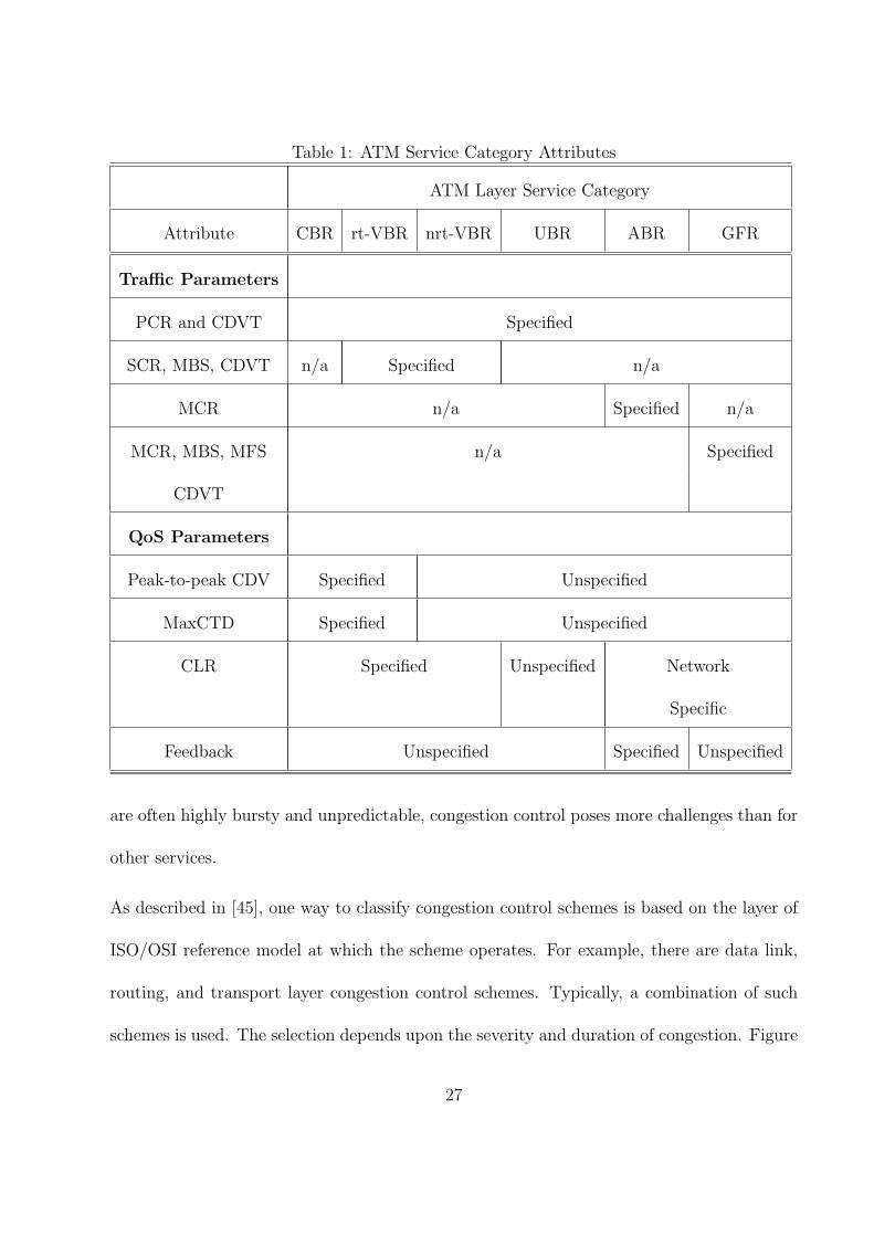
Table 1: ATM Service Category Attributes
ATM Layer Service Category
Attribute CBR rt-VBR nrt-VBR UBR ABR GFR
Traffic Parameters
PCR and CDVT Specified
SCR, MBS, CDVT n/a Specified n/a
MCR n/a Specified n/a
MCR, MBS, MFS n/a Specified
CDVT
QoS Parameters
Peak-to-peak CDV Specified Unspecified
MaxCTD Specified Unspecified
CLR Specified Unspecified Network
Specific
Feedback Unspecified Specified Unspecified
are often highly bursty and unpredictable, congestion control poses more challenges than for
other services.
As described in [45], one way to classify congestion control schemes is based on the layer of
ISO/OSI reference model at which the scheme operates. For example, there are data link,
routing, and transport layer congestion control schemes. Typically, a combination of such
schemes is used. The selection depends upon the severity and duration of congestion. Figure
27

7 shows how the duration of congestion affects the choice of the method.
Figure 7: Congestion techniques for various congestion durations
One method to avoid network congestion is to accept a new ATM connection during connec-
tion setup phase only when sufficient network resources are available to provide the accept-
able QoS. This is called connection admission control (CAC), which is needed for connections
where the QoS must be guaranteed. The “busy” tone on telephone networks is an example
of CAC. Mechanisms for CAC are currently not standardized and are at the discretion of
the network operators.
In addition to CAC, [26] also allows traffic shaping using a generic cell rate algorithm (GCRA)
and binary explicit forward congestion indication (EFCI) feedback congestion control. These
mechanisms are described next.
Generic Cell Rate Algorithm (GCRA) The GCRA is also called the “leaky bucket”
algorithm, which converts a bursty stream into a more regular pattern. This algorithm
essentially works by putting all arriving cells into a bucket, which is drained at the sustained
cell rate. If too many cells arrive at once, the bucket may overflow. The overflowing cells
28

are called non-conforming and may or may not be admitted into the network. If admitted,
the cell loss priority (CLP) bit of the non-conforming cells may be set so that they will be
the first to be discarded in case of overload.
The leaky bucket algorithm is often used by the network to ensure that the input meets the
pre-negotiated parameters such as the sustained and peak cell rates. Such “traffic shaping”
algorithms are open loop in the sense that the parameters cannot be changed dynamically
if congestion is detected after negotiation. In a closed-loop (feedback) scheme, however,
sources are informed dynamically about the congestion state of the network and are asked
to increase or decrease their input rate.
Feedback Congestion Control As described earlier in Figure 3, four bits of the cell
header at the user-network interface (UNI) are reserved for generic flow control (GFC).
Originally, the plan was to use these bits to flow control the source. The discussions in ATM
Forum eventually led to the development of end-to-end congestion control scheme instead of
GFC.
An effective congestion control scheme must satisfy several key criteria. In addition to being
able to maximally utilize available bandwidth, a good scheme must also provide fairness
of network resources to users. Moreover, it must be scalable to a large number of nodes
and links with various capacities, robust against slight mistuning of parameters and loss of
control cells, as well as low in switch complexity and buffer requirement.
The ATM Forum initially considered the use of the explicit forward congestion indication
(EFCI) bit in the ATM cell headers to mark congestion in the switches [41]. This scheme
29

was to be based on DECbit scheme [53]. The forum finally adopted an explicit rate-based
indication scheme based on [33].
The available bit rate (ABR) method of traffic management works as follows. The sources
periodically send resource management (RM) cells, which indicate their current rate and the
desired rate. The switches along the path adjust the desired rate down. The destination
returns the RM cells to the sources. The sources then adjust their rate to that indicated in
the RM cells. The algorithm for deciding the rate allocated by a switch is not specified and
is left for the vendors to design. For examples of such algorithms, see [46, 47, 56].
The rate-based congestion control approach and its development at the ATM Forum is
described in more detail in [26]. Other reference sources include the review papers of [43, 32].
4 Switch Architecture
Perhaps the most developed aspect of ATM is the switch architecture. Over the past decade,
a vast amount of research efforts have been made on studying and designing ATM switches.
The field has now become a mature research area and a number of tutorial articles have
appeared in the literature. The design of ATM switch architectures is at the discretion
of switch vendors. Basic principles of switch design and examines the influence of traffic
patterns on the design methodologies are discussed in [34, 38, 29, 61].
ATM switches are high-speed packet switches specialized to process and forward ATM cells
(packets). Because ATM is a connection-oriented protocol, ATM switches must establish a
30

virtual connection from one of its input ports to an output port before forwarding incoming
ATM cells along that virtual connection.
A generic ATM switch architecture with N input ports and N output ports is shown in Figure
8. The functions of an ATM switching system may be divided broadly into the three planes
as in [34].
• User Plane: The main function of an ATM switch is to relay user data cells from input
ports to the appropriate output ports. The switch processes only the cell headers and
the payload is carried transparently. As soon as the cell comes in through the input
port, the virtual path identifier/virtual channel identifier (VPI/VCI) information is
derived and used to route the cells to the appropriate output ports. This function
can be divided into three functional blocks: the input module at the input port, the
cell switch fabric (sometimes referred to as switch matrix) that performs the actual
routing, and the output modules at the output ports.
• Control Plane: This plane represents functions related to the establishment and
control of the VP/VC connections. Unlike the user data cells, information in the
control cells payload is not transparent to the network. The switch identifies signaling
cells, and even generates some itself. The connection admission control (CAC) carries
out the major signaling functions required. Signaling information may/may not pass
through the cell switch fabric, or maybe exchanged through a signaling network such
as SS7.
• Management Plane: The management plane is concerned with monitoring the con-
31

trolling the network to ensure its correct and efficient operation. These operations
can be subdivided as fault management functions, performance management func-
tions, configuration management functions, security management functions, account-
ing management and traffic management. These functions can be represented as being
performed by the functional block switch management. The switch management is
responsible for supporting the ATM layer operations and maintenance (OAM) proce-
dures. OAM cells may be recognized and processed by the ATM switch. The switch
must identify and process OAM cells, maybe resulting in generating OAM cells. As
with signaling cells, OAM cells may/may not pass through cell switch fabric. Switch
management also supports the interim local management interface (ILMI) of the UNI.
The Switch Management contains, for each UNI, a UNI management entity (UME),
which may use SNMP.
Figure 8: A generic ATM switch architecture
32

ATM cells containing user data are received at the input ports, and the input port processors
prepare the cells for routing through the switch fabric. The fabric in the center of the
switching system provides the interconnections between input port processors and output
port processors. The output port processors prepare the outgoing user cells for transmission
from the switch. User cell forwarding is characterized by parallelism and high-speed hardware
processing. The ATM protocol was intentionally streamlined to allow incoming cells to be
processed simultaneously in hardware and routed through the switch fabric in parallel. Thus,
ATM switches have been able to realize high-end performance in terms of throughput and
cell forwarding delay.
An ATM switch contains a set of input ports and output ports, through which it is inter-
connected to users, other switches, and other network elements. It might also have other
interfaces to exchange control and management information with special purpose networks.
Connection control, sometimes called the control plane, refers to the functions related to the
establishment and termination of ATM virtual connections. Connection control functions
generally encompass: exchange and processing of signaling information; participation in
routing protocols; and decisions on admission or rejection of new connection requests.
The cell switch fabric is primarily responsible for routing of data cells and possibly signaling
and management cells as well. Other possible functions include: cell buffering, traffic con-
centration and multiplexing redundancy for fault tolerance, multicasting or broadcasting,
cell scheduling based on delay priorities, congestion monitoring and activation of explicit
forward congestion indication (EFCI). More details about switch fabrics can be found in
33

[34, 38, 29].
Network management is currently carried out by SNMP (simple network management pro-
tocol), the standard protocol for managing data networks. ATM switches typically support
an SNMP agent and an ATM MIB (management information base).
4.1 Switch Interface
4.1.1 Input Modules
The input module first terminates the incoming signal (for example a SONET signal) and
extracts the ATM cell stream. This involves signal conversion and recovery, processing
SONET overhead, and cell delineation and rate decoupling. After that, for each ATM cell
the following functions should be performed:
• Error checking the header using the header error control (HEC) field
• Validation and translation of VPI/VCI values
• Determination of the destination output port
• Passing signaling cells to CAC and OAM cells to switch management
• UPC/UNC for each VPC/VCC
• Addition of an internal tag containing internal routing and performance monitoring
information for use only within the switch
34

4.1.2 Output Modules
Output Modules prepare the ATM cell streams for physical transmission by:
• Removing and processing the internal tag
• Possible translation of VPI/VCI values
• HEC field generation
• Possible mixing of cells from CAC and switch management with outgoing cell streams
• Cell rate decoupling
• Mapping cells to SONET payloads and generation of SONET overhead
• Cconversion of the digital bitstream to an optical signal
4.2 Connection Admission Control (CAC)
CAC establishes, modifies and terminates virtual path/channel connections. More specifi-
cally, it is responsible for:
• High-layer signaling protocols
• Signaling ATM adaptation layer (AAL) functions to interpret or generate signaling
cells
• Interface with a signaling network
35

• Negotiation of traffic contracts with users requesting new VPCs/VCCs
• Renegotiation with users to change established VPCs/VCCs
• Allocation of switch resources for VPCs/VCCs, including route selection
• Admission/rejection decisions for requested VPCs/VCCs
• Generation of UPC/NPC parameters
If the CAC is centralized, a single processing unit would receives signaling cells from the
input modules, interpret them, and perform admission decisions and resource allocation
decisions for all the connections in the switch. CAC functions may be distributed to blocks
of input modules where each CAC has a smaller number of input ports. This is much harder
to implement, but solves the connection control processing bottleneck problem for large
switch sizes, by dividing this job to be performed by parallel CACs. A lot of information
must be communicated and coordinated among the various CACs [34, 38]. Some of the
distributed CAC functions can also be distributed among output modules which can handle
encapsulation of high-layer control information into outgoing signaling cells.
4.3 Switch Management
Switch management physical layer OAM, ATM layer OAM, configuration management of
switch components, security control for the switch database, usage measurements of the
switch resources, traffic management, administration of a management information base,
36
customer-network management, interface with operations systems and finally support of
network management.
Switch management is difficult because management covers an extremely wide spectrum of
activities. In addition, the level of management functions implemented in the switch can
vary between minimal and complex.
Switch management must perform a few basic tasks. It must carry out specific management
responsibilities, collect and administer management information, communicate with users
and network managers, and supervise and coordinate all management activities. Manage-
ment functions include fault management, performance management, configuration manage-
ment, accounting management, security management, and traffic management. Carrying out
these functions entails a lot of intraswitch communication between the switch management
and other functional blocks.
A centralized switch management can be a performance bottleneck if it is overloaded by
processing demands. Hence, switch management functions can be distributed among input
modules, but a lot of coordination would be required. Each distributed input module switch
management unit can monitor the incoming user data cell streams to perform accounting
and performance measurement. Output module switch management units can also monitor
outgoing cell streams [34, 38].
37

4.4 The Cell Switch Fabric
The cell switch fabric is primarily responsible for transferring cells between the other func-
tional blocks (routing of data cells and possibly signaling and management cells as well).
Other possible functions include:
• Cell buffering
• Traffic concentration and multiplexing
• Redundancy for fault tolerance multicasting or broadcasting
• Cell scheduling based on delay priorities
• Congestion monitoring and activation of explicit forward congestion indication (EFCI)
4.4.1 Concentration, Expansion, and Multiplexing
Traffic needs to be concentrated at the inputs of the switching fabric to better utilize the
incoming link connected to the switch. The concentrator aggregates the lower variable bit
rate traffic into higher bit rate for the switching matrix to perform the switch at standard
interface speed. The concentration ratio is highly correlated with the traffic characteristics,
so it needs to be dynamically configured. The concentrator can also aid in dynamic traffic
distribution to multiple routing and buffering planes, and duplication of traffic for fault
tolerance. At the outputs of the routing and buffering fabric, traffic can be expanded and
redundant traffic can be combined.
38

4.4.2 Routing and Buffering
The routing and buffering functions are the two major functions performed by the cell switch
fabric. The input module attaches a routing tag to each cell, and the switch fabric simply
routes the arriving cells from its inputs to the appropriate outputs. Arriving cells may be
aligned in time by means of single-cell buffers. Because cells may be addressed to the same
output simultaneously, buffers are needed. Several routing and buffering switch designs have
aided in setting the important switch design principles. All current approaches employ a
high degree of parallelism, distributed control, and the routing function is performed at the
hardware level.
Traditionally switching has been defined to encompass either space switching or time switch-
ing or combinations of both techniques. The classification adopted here is slightly different
in the sense that it divides the design approaches under the following four broad categories
[34]: (1) shared memory, (2) shared Medium, (3) fully interconnected, and (4) space division.
Shared Memory Approach: Figure 9 illustrates the basic structure of a shared memory
switch. Here incoming cells are converted from serial to parallel form, and written sequen-
tially to a dual-port random access memory. A memory controller decides the order in
which cells are read out of the memory, based on the cell headers with internal routing tags.
Outgoing cells are demultiplexed to the outputs and converted from parallel to serial form.
This approach is an output queueing approach, where the output buffers all physically belong
to a common buffer pool. The approach is attractive because it achieves 100% throughput
under heavy load. The buffer sharing minimizes the amount of buffers needed to achieve a
39

Figure 9: Basic structure of a shared-memory switch
specified cell loss rate. This is because if a large burst of traffic is directed to one output
port, the shared memory can absorb as much as possible of it.
The approach, however, suffers from a few drawbacks. The shared memory must operate
N times faster than the port speed because cells must be read and written one at a time.
As the access time of memory is physically limited, the approach is not very scalable. The
product of the number of ports times port speed (NV) is limited. In addition, the centralized
memory controller must process cell headers and routing tags at the same rate as the memory.
This is difficult for multiple priority classes, complicated cell scheduling, multicasting and
broadcasting.
Shared Medium Approach: Cells may be routed through a shared medium, like a ring,
bus or dual bus. Time-division multiplexed buses are a popular example of this approach,
40

and Figure 10 illustrates their structure. Arriving cells are sequentially broadcast on the
TDM bus in a round-robin manner. At each output, address filters pass the appropriate
cells to the output buffers, based on their routing tag. The bus speed must be at least NV
for cells/s to eliminate input queueing.
Figure 10: A shared bus switch (adapted from Chen and Liu [34])
The outputs are modular, which makes address filters and output buffers easy to implement.
Also the broadcast-and-select nature of the approach makes multicasting and broadcasting
straightforward. As a result, many such switches have been implemented, such as IBM’s
Packetized Automated Routing Integrated System (PARIS) and plaNET, NEC’s ATM Out-
put Buffer Modular Switch (ATOM), and Fore Systems’ ForeRunner ASX-100 to mention a
few [52]. The Synchronous Composite Packet Switching (SCPS), which uses multiple rings
is also one of the most famous experiments of shared medium switches [55].
However, because the address filters and output buffers must operate at the shared medium
speed, which is N times faster than the port speed, this places a physical limitation on the
scalability of the approach. In addition, unlike the shared memory approach, output buffers
41

are not shared, which requires more total amount of buffers for the same cell loss rate.
Fully Interconnected Approach: In this approach, independent paths exist between all N
squared possible pairs of inputs and outputs. Hence arriving cells are broadcast on separate
buses to all outputs and address filters pass the appropriate cells to the output queues. This
architecture is illustrated in Figure 11.
Figure 11: A fully interconnected switch (adapted from Chen and Liu [34])
This design has many advantages. As before, all queueing occurs at the outputs. In addition,
multicasting and broadcasting are natural, like in the shared medium approach. Address
filters and output buffers are simple to implement and only need to operate at the port
speed. Because all of the hardware operates at the same speed, the approach is scalable to
any size and speed. Fujitsu’s bus matrix switch and GTE Government System’s SPANet are
examples of switches in which this design was adopted.
Unfortunately, the quadratic growth of buffers limits the number of output ports for practical
reasons. However, the port speed is not limited except by the physical limitation on the speed
42

of the address filters and output buffers.
The Knockout switch developed by AT&T was an early prototype where the amount of
buffers was reduced at the cost of higher cell loss [52, 55]. Instead of N buffers at each
output, it was proposed to use only a fixed number of buffers L for a total of NxL buffers.
This technique was based on the observation that it is unlikely that more than L cells will
arrive for any output at the same time. It was argued that selecting the L value of 8 was
sufficient for achieving a cell loss rate of 1/1 million under uniform random traffic conditions
for large values of N.
Space Division Approach: The crossbar switch is the simplest example of a matrix-like
space division fabric that physically interconnects any of the N inputs to any of the N outputs.
Multistage interconnection networks (MINs), which are more tree-like structures, were then
developed to reduce the N squared crosspoints needed for circuit switching, multiprocessor
interconnection and, more recently, packet switching.
One of the most common types of MINs is the banyan network. It is named for its resem-
blance to the roots of the Banyan tropical tree which crossover in complex patterns. The
banyan network is constructed of an interconnection of stages of switching elements. A basic
2x2 switching element can route an incoming cell according to a control bit (output address).
If the control bit is 0, the cell is routed to the upper port address, otherwise it is routed to
the lower port address.
In general, to construct an NxN banyan network, the nth stage uses the n
th bit of the output
address to route the cell. For N = 2 to the power of n, the banyan will consist of n = log
43

to the base 2 of N stages, each consisting of N/2 switching elements. A MIN is called self-
routing when the output address completely specifies the route through the network (also
called digit-controlled routing).
The banyan network technique is popular because switching is performed by simple switching
elements, cells are routed in parallel, all elements operate at the same speed (so there is no
additional restriction on the size N or speed V), and large switches can be easily constructed
modularly and recursively and implemented in hardware.
It is clear that in a banyan network, there is exactly one path from any input to any output.
Regular banyans use only one type of switching element, and SW-banyans are a subset of
regular banyans, constructed recursively from LxM switching elements.
Delta networks are a subclass of SW-banyan networks, possessing the self-routing property.
There are numerous types of delta networks, such as rectangular delta networks (where the
switching elements have the same number of outputs as inputs), omega, flip, cube, shuffle-
exchange (based on a perfect shuffle permutation) and baseline networks. A delta-b network
of size NxN is constructed of bxb switching elements arranged in log to the base b of N
stages, each stage consisting of N/b switching elements [55].
Unfortunately, since banyan networks have less than N squared crosspoints, routes of two
cells addressed to two different outputs might conflict before the last stage. When this
situation, called internal blocking, occurs, only one of the two cells contending for a link can
be passed to the next stage, so overall throughput is reduced. A solution to this problem is
to add a sort network (such as a Batcher bitonic sort network) to arrange the cells before the
44

banyan network. This will be internally non-blocking for cells addressed to different outputs
[55]. However, if cells are addressed to the same output at the same time, the only solution
to the problem is buffering. Buffers can be placed at the input of the Batcher network, but
this can cause ”head-of-line” blocking, where cells wait for a delayed cell at the head of the
queue to go through, even if their own destination output ports are free. This situation can
be remedied by First-In-Random-Out buffers, but these are quite complex to implement.
Alternatively, buffers may be placed internally within the banyan switching elements. Thus
if two cells simultaneously attempt to go to the same output link, one of them is buffered
within the switching element. This internal buffering can also be used to implement a
backpressure control mechanism, where queues in one stage of the banyan will hold up cells
in the preceding stage by a feedback signal. The backpressure may eventually reach the
first stage, and create queues at the banyan network inputs [34]. It is important to observe
that internal buffering can cause head-of-line blocking at each switching element, and hence
it does not achieve full throughput. Awdeh and Mouftah [30] have designed a delta-based
ATM switch with backpressure mechanism capable of achieving a high throughput, while
significantly reducing the overall required memory size.
A third alternative is to use a recirculating buffer external to the switch fabric. This technique
has been adopted in Bellcore’s Sunshine and AT&T’s Starlite wideband digital switch [55].
Here output conflicts are detected after the Batcher sorter, and a trap network selects a
cell to go through, and recirculates the others back to the inputs of the Batcher network.
Unfortunately, this approach requires complicated priority control to maintain the sequential
order of cells and increases the size of the Batcher network to accommodate the recirculating
45

cells [34].
As discussed before, output buffering is the most preferable approach. However, banyan
networks cannot directly implement it since at most one cell per cell time is delivered to
every output. Possible ways to work around this problem include:
• Increasing the speed of internal links
• Routing groups of links together
• Using multiple banyan planes in parallel
• Using multiple banyan planes in tandem or adding extra switching stages
Apart from banyan networks, many types of MINs with multiple paths between inputs and
outputs exist. Classical examples include the non-blocking Benes and Clos networks, the
cascaded banyan networks, and the randomized route banyan network with load distribution
(which eliminates internal buffering). Combining a number of banyan planes in parallel can
also be used to form multipath MINs. The multipath MINs achieve more uniform traffic
distribution to minimize internal conflicts, and exhibit fault tolerance. However if cells
can take independent paths with varying delays, a mechanism is needed to preserve the
sequential ordering of cells of the same virtual connection at the output. Since this might
involve considerable processing, it is better to select the path during connection setup and
fix it during the connection. Special attention must be paid during path selection to prevent
unnecessary blocking of subsequent calls.
46

4.5 Switch Design Principles
4.5.1 Internal Blocking
A fabric is said to be internally blocking if a set of N cells addressed to N different outputs
can cause conflicts within the fabric. Internal blocking can reduce the maximum possible
throughput. Banyan networks are blocking, whereas TDM buses where the bus operates at
least N times faster than the port speed are internally nonblocking. By the same concept,
shared memory switches which can read and write at the rate of NV cells per second are
internally non-blocking, since if N cells arrive for N different outputs, no conflicts will occur.
Hence, to prevent internal blocking, shared resources must operate at some factor greater
than the port speed. Applying this to banyan networks, the internal links need to run square
root of N times faster than the highest speed incoming link [52]. This factor limits the
scalability and throughput of the switch. Coppo et al. [35] have developed a mathematical
model for analyzing the optimal blocking probability versus complexity tradeoff.
4.5.2 Buffering Approaches
Buffering is necessary in all design approaches. For instance, in a banyan network, if two
cells addressed to the same output successfully reach the last switching stage at the same
time, output contention occurs and must be resolved by employing buffering. The location
and size of buffers are important issues that must be decided [52].
There are four basic approaches to the placement of buffers. These basic approaches are
illustrated in Figure 12. The literature abounds with comparative studies of these, aug-
47

mented with numerous queueing analysis and simulation results. Uniform random traffic, as
well as bursty traffic have been examined. Although each approach has its own merits and
drawbacks, output queueing is the preferred technique so far.
Figure 12: The various buffering approaches (Combined from Chen and Liu [34] and Onvural
[52])
Input Queueing: Buffers at the input of an internally nonblocking space division fabric
(such as Batcher banyan network) illustrate this type of buffering. This approach suffers
from head-of-the-line blocking. When two cells arrive at the same time and are destined to
48

the same output, one of them must wait in the input buffers, preventing the cells behind it
from being admitted. Thus capacity is wasted.
Several methods have been proposed to tackle the head-of-the-line blocking problem, but
they all exhibit complex design. Increasing the internal speed of the space division fabric by
a factor of four, or changing the first-in-first-out (FIFO) discipline are two examples of such
methods.
Output Queueing: This type of buffering can be evident by examining the buffers at the
output ports of a shared bus fabric. This approach is optimal in terms of throughput and
delays, but it needs some means of delivering multiple cells per cell time to any output.
Hence, either the output buffers must operate at some factor times the port speed, or there
should be multiple buffers at each output. In both cases, the throughput and scalability are
limited, either by the speedup factor or by the number of buffers.
Internal Queueing: Buffers can be placed within the switching elements in a space division
fabric. For instance, in a banyan network, each switching element contains buffers at its
inputs to store cells in the event of conflict. Again, head-of-the-line blocking might occur
within the switching elements, and this significantly reduces throughput, especially in the
case of small buffers or larger networks. Internal buffers also introduce random delays within
the switch fabric, causing undesirable cell delay variation.
Recirculating Buffers: This technique allows cells to re-enter the internally nonblocking
space division network. This is needed when more than one cell is addressed to the same out-
put simultaneously, so the extra cells need to be routed to the inputs of the network through
49

the recirculating buffers. Although this approach has the potential for achieving the optimal
throughput and delay performance of output queueing, its implementation suffers from two
major complexities. First, the switching network must be large enough to accommodate the
recirculating cells. Second, a control mechanism is essential to sequentially order the cells.
4.6 Buffer Sharing
The number and size of buffers has a significant impact on switch design. In shared memory
switches, the central buffer can take full advantage of statistical sharing, thus absorbing large
traffic bursts to any output by giving it as much as is available of the shared buffer space.
Hence, it requires the least total amount of buffering. For a random and uniform traffic and
large values of N, a buffer space of only 12 N cells is required to achieve a cell loss rate of
1/10 to the power of 9, under a load of 0.9.
For a TDM bus fabric with N output buffers, and under the same traffic assumptions as
before, the required buffer space is about 90 N cells. Also a large traffic burst to one output
cannot be absorbed by the other output buffers, although each output buffer can statistically
multiplex the traffic from the N inputs. Thus, buffering assumes that it is improbable that
many input cells will be directed simultaneously to the same output.
Neither statistical multiplexing between outputs or at any output can be employed with fully
interconnected fabrics with N squared output buffers. Buffer space grows exponentially in
this case.
50

5 New Developments
ATM could not fulfill the promise of providing a single integrated technology for LANs,
public networks, and user services. IP was shown to provide such integration in a more
flexible, more scalable, and less complex way than ATM. However, as it happens usually
with technologies, the best ideas are borrowed by other solutions. In the case of ATM,
various important concepts are inherited by other technologies, such as MPLS. Whereas
other technologies, such as DSL, FTTP, and UMTS use ATM and AAL layers.
5.1 Multiprotocol label switching - (MPLS)
Multiprotocol label switching (MPLS) [23, 19, 21, 22, 57] is a data-carrying mechanism
which emulates some properties of a circuit-switched network over a packet-switched network.
MPLS has emerged as an elegant solution to meet the bandwidth-management and service
requirements for next-generation Internet protocol (IP)based backbone networks. MPLS
addresses issues related to scalability and routing (based on QoS and service quality metrics)
and can exist over existing asynchronous transfer mode (ATM) and frame-relay networks.
MPLS is standardized by IETF in RFC 3031 [57]. For ATM-MPLS network interworking
see [6].
Although the underlying protocols and technologies are different, both MPLS and ATM
provide a connection-oriented service for transporting data across computer networks. In
both technologies connections are signaled between endpoints, connection state is maintained
at each node in the path and encapsulation techniques are used to carry data across the
51
connection. Excluding differences in the signaling protocols (RSVP/LDP for MPLS and
PNNI for ATM) there still remain significant differences in the behavior of the technologies.
The most significant difference is in the transport and encapsulation methods. MPLS is able
to work with variable length packets whereas ATM transports fixed-length (53 byte) cells.
Packets must be segmented, transported and re-assembled over an ATM network using an
adaption layer, which adds significant complexity and overhead to the data stream. MPLS,
on the other hand, simply adds a label to the head of each packet and transmits it on the
network.
Differences exist, as well, in the nature of the connections. An MPLS connection (LSP) is
uni-directional, allowing data to flow in only one direction between two endpoints. Estab-
lishing two-way communications between endpoints requires a pair of LSPs to be established.
Because two LSPs are required for connectivity, data flowing in the forward direction may
use a path different from data flowing in the reverse direction. ATM point-to-point connec-
tions (Virtual Circuits), on the other hand, are bi-directional, allowing data to flow in both
directions over the same path (bi-directional are only SVC ATM connections; PVC ATM
connections are uni-directional).
Both ATM and MPLS support tunneling of connections inside connections. MPLS uses label
stacking to accomplish this while ATM uses virtual paths. MPLS can stack multiple labels
to form tunnels within tunnels. The ATM virtual path indicator (VPI) and virtual circuit
indicator (VCI) are both carried together in the cell header, limiting ATM to a single level
of tunneling.
52

The biggest single advantage that MPLS has over ATM is that it was designed from the
start to be complimentary to IP. Modern routers are able to support both MPLS and IP
natively across a common interface allowing network operators great flexibility in network
design and operation. ATM’s incompatibilities with IP require complex adaptation making
it largely unsuitable in today’s predominantly IP networks.
5.2 Technologies exploiting ATM and AAL layers
DSL
DSL or xDSL [13], is a family of technologies that provide digital data transmission over the
wires of a local telephone network. DSL originally stood for digital subscriber loop, although
in recent years, many have adopted digital subscriber line as a more marketing-friendly term
for the most popular version of DSL, ADSL over UNE.
Typically, the download speed of DSL ranges from 128 kilobits per second (kbps) to 24,000
kbps depending on DSL technology and service level implemented. Upload speed is lower
than download speed for asymmetric digital subscriber line (ADSL) and equal to download
speed for symmetric digital subscriber line (SDSL).
Many DSL technologies implement an ATM layer [15] over the low-level bitstream layer to
enable the adaptation of a number of different technologies over the same link.
DSL implementations may create bridged or routed networks. In a bridged configuration,
the group of subscriber computers effectively connect into a single subnet. The earliest
implementations used DHCP to provide network details such as the IP address to the sub-
53

scriber equipment, with authentication via MAC address or an assigned host name. Later
implementations often use PPP over Ethernet (PPPoE) [50] or ATM (PPPoA) [48], while
authenticating with a userid and password and using PPP mechanisms to provide network
details.
PPPoA, Point-to-Point Protocol (PPP) over ATM, is a network protocol for encapsulating
PPP frames in ATM AAL5. It is used mainly with cable modem, DSL and ADSL services.
PPPoA offers standard PPP features such as authentication, encryption, and compression.
If it is used as the connection encapsulation method on an ATM based network it can reduce
overhead slightly (around 0.58%) in comparison to PPPoE [50]. It also avoids the issues
that PPPoE suffers from, related to having a MTU lower than that of standard ethernet
transmission protocols. It also supports (as does PPPoE) the encapsulation types: VC-MUX
and LLC based. PPPoA is specified in RFC 2364 [48].
Fiber to the Premises
Fiber to the premises (FTTP) or fiber to the home (FTTH) [17] is a broadband telecommu-
nications system based on fiber-optic cables and associated optical electronics for delivery
of multiple advanced services such as the triple play of telephone, broadband Internet, and
television all the way to the home or business.
Two competing FTTP technologies are active FTTP, also called active Ethernet, and passive
optical network (PON) architectures.
Active FTTP networks utilize powered (i.e., “active”) electronic equipment in neighbor-
54

hoods, usually one equipment cabinet for every 400 to 500 subscribers. This neighborhood
equipment performs layer 2/layer 3 switching and routing, offloading full layer 3 routing to
the carrier’s central office. The IEEE 802.3ah standard enables service providers to deliver
up to 100 Mbps full-duplex over one single-mode optical fiber to the premises depending on
the provider.
Passive optical network (PON) FTTP networks on the other hand avoid the placement of
electronics in the field. PON networks use passive splitters to distribute fiber to individual
homes. One fiber is optically split into 16, 32, or 64 fibers, depending on the manufacturer,
which are then distributed to residential or business subscribers. In PON architectures, the
switching and routing is done at the carrier’s central office.
The International Telecommunications Union (ITU) has standardized on two generations of
PON. The older ITU-T G.983 standard is based on ATM, and has therefore been referred
to as APON (ATM PON) [7]. Further improvements to the original APON standard — as
well as the gradual falling out of favor of ATM as a protocol — led to the full, final version
of ITU-T G.983 being referred to more often as Broadband PON, or BPON. A typical
APON/BPON provides 622 megabits per second (Mbps) of downstream bandwidth and 155
Mbps of upstream traffic, although the standard accommodates higher rates.
UMTS Core Network
ATM is also the data transmission method used within the universal mobile telecommuni-
cations system (UMTS) core network [24]. ATM adaptation layer type 2 (AAL2) handles
55

circuit-switched connections. Packet connection protocol AAL5 is used for data delivery.
6 Conclusion
In this brief chapter, we have discussed several key aspects of ATM. ATM is a cell-oriented
switching and multiplexing technology that uses fixed-length cells to carry various types of
traffic, such as data, voice, video, multimedia, and so on. through multiple classes of services.
ATM is a connection-oriented technology, in which a connection is established between the
two endpoints before the actual data exchange begins.
The ATM protocol reference model is divided into three layers: the ATM adaptation layer
(AAL), the ATM layer, and the physical layer, and three planes: user/control plane, layer
management and plane management. Four types of AALs were proposed, each supporting
a different type of traffic or service that could be used on ATM networks.
ATM was designed to deliver guaranteed quality of service on demand while maximizing the
utilization of available network resources. Therefore, effective traffic management mecha-
nisms were specified.
ATM has been a partial success as a technology, with widespread deployment, but generally
only used as a transport for IP traffic; its goal of providing a single integrated technology
for LANs, public networks, and user services has largely failed. This role of integrator in
today’s networks in played by IP. However, various important ATM concepts are inherited
by other technologies, such as MPLS, DSL, and FTTH. It is expected that the best ideas
56

and lessons of ATM will be used in designing the next Internet.
7 GLOSSARY
AAL - ATM adaptation layer.
ABR - available bit rate.
ANSI - American National Standards Institute.
ATM - asynchronous transfer mode.
ATMF - ATM Forum.
B-ISDN - broadband-integrated services digital network.
BT - burst tolerance.
CAC - connection admission control.
CBR - constant bit rate.
CDV - cell delay variation.
CDVT - cell delay variation tolerance.
CLP - cell loss priority.
CLR - cell loss ratio.
CRC - cyclic redundancy check.
CS - convergence sublayer.
57

CTD - cell transfer delay.
EFCI - explicit forward congestion indication.
FTP - file transfer protocol.
GCRA - generic cell rate algorithm.
GFC - generic flow control.
HEC - header error check.
IETF - Internet Engineering Task Force.
ISDN - integrated services digital network.
ITU - International Telecommunications Union.
LAN - local area network.
LDP - label distribution protocol.
MAC - medium access control.
MIB - management information base.
MBS - maximum burst size.
MCR - minimum cell rate.
MFA Forum - MPLS frame relay ATM Forum.
MPLS - multi-protocol label switching.
NDIS - network driver interface specification.
NNI - network-to-node interface, or network to network interface.
58
nrt-VBR - non real-time VBR.
PCR - peak cell rate.
PDH - plesiochronous digital hierarchy.
PNNI - private network-to-network interface.
PTI - payload type identifier.
PVC - permanent virtual circuit.
QoS - quality of service.
rt-VBR - real-time VBR.
RSVP - resource reservation protocol.
SAR - segmentation and reassembly.
SCR - sustainable cell rate.
SDH - synchronous digital hierarchy.
SONET - synchronous optical network.
SSCOP - service specific connection oriented protocol.
SVC - switched virtual circuit.
VBR - variable bit rate.
VC - virtual channel.
VCC - virtual channel connection.
VCI - virtual channel identifier.
59

VPC - virtual path connection.
VPI - virtual path identifier.
UBR - unspecified bit rate.
UNE - unbundled network elements.
UMTS - Universal Mobile Telecommunication System.
UNI - user-to-network interface.
References
[1] ”AAL1 Circuit Emulation over Packet Switched Networks Version 1.0,” ATM Fo-
rum Techical Committee, January 2005, http://www.mfaforum.org/ftp/pub/approved-
specs/ af-arch-0204.000.pdf
[2] ”Asymmetric Digital Subscriber Line (ADSL),” IEC Tutorial,
http://www.iec.org/acrobat.asp?filecode=4
[3] ATM, http://www.telecomspace.com/vop-atm.html.
[4] ”ATM Fundamentals,” IEC Tutorial, 2005, http://www.iec.org/online/tutorials/
atm fund/index.html.
[5] ”ATM Inter-Network Interface (AINI) Specification Version 1.1,” ATM Forum Techical
Committee, September 2002, http://www.mfaforum.org/ftp/pub/approved-specs/ af-
cs-0125.002.pdf
60

[6] ”ATM-MPLS Network Interworking Version 2.0,” ATM Forum Techical Committee,
August 2003, http://www.mfaforum.org/ftp/pub/approved-specs/ af-aic-0178.001.pdf
[7] ”ATM Passive Optical Networks,” IEC Tutorial, http://www.iec.org/acrobat.asp? file-
code=10.
[8] ”ATM Tutorial,” http://www.npac.syr.edu/users/mahesh/homepage/atm tutorial/.
[9] ”ATM User-Network Interface (UNI) Signalling Specification Version 4.1,” ATM Forum
Techical Committee, April 2002, http://www.mfaforum.org/ftp/pub/approved-specs/
af-sig-0061.001.pdf
[10] ”ATM User-Network Interface (UNI) Specification Version 4.1,” ATM Forum Techi-
cal Committee, November 2002, http://www.mfaforum.org/ftp/pub/approved-specs/
af-arch-0193.000.pdf
[11] B-ISDN Intercarrier Interface (B-ICI) Specification, Version 1.0. ATM Forum, May
1994.
[12] ”Converged Data Networks, Bringing Together ATM and MPLS Technologies,” ATM
Forum, White Paper, April 2004, http://www.mfaforum.org/education/downloads/
CDNwhtpapr.final.pdf.
[13] ”Digital Subscriber Line (DSL) Testing,” IEC Tutorial,
http://www.iec.org/acrobat.asp?filecode=35
[14] ”Delivering Video over Packet Networks,” ATM Forum, White Paper, April 2003,
http://www.mfaforum.org/education/downloads/Del.Vid.Final.pdf.
61

[15] ”DSL and the Evolution of ATM Networks,” IEC Tutorial,
http://www.iec.org/acrobat.asp?filecode=33
[16] ”EPON,” http://www.ieee802.org/3/
[17] Michael Kunigonis, ”FTTH Explained,” IEC Tutorial,
http://www.iec.org/acrobat.asp?filecode=51
[18] IEEE Online Standards, http://standards.ieee.org/catalog/olis/lanman.html.
[19] ”Introduction to MPLS,” http://www.riverstonenet.com/support/mpls/intro to mpls.htm.
[20] Metro Ethernet Forum, http://www.metroethernetforum.org/.
[21] Multiprotocol Label Switching, IETF Chapter, http://www.ietf.org/html.charters/mpls-
charter.html.
[22] ”Multiprotocol Label Switching,” IEC Tutorial, http://www.iec.org/acrobat.asp?filecode=94
[23] MPLS Frame Relay ATM - MFA Forum, http://www.mfaforum.org/.
[24] ”Overview of GSM, GPRS, and UMTS,” http://www.cisco.com/univercd/cc/td/doc/product/wireless/moblwrls/cmx/mmg
[25] ”Private Network-Network Interface Specification Version 1.1 (PNNI 1.1)”, ATM Fo-
rum, Techical Committee, April 2002, http://www.mfaforum.org/ftp/pub/approved-
specs/ af-pnni-0055.001.pdf
[26] ”Traffic Management Specification Version 4.1,” ATM Forum, Techical Committee,
March 1999, http://www.mfaforum.org/ftp/pub/approved-specs/ af-tm-0121.000.pdf
62

[27] ”XEPON,” http://grouper.ieee.org/groups/802/3/10GEPON study/index.html
[28] G. J. Armitage, ”Multicast and Multiprotocol support for ATM based Internets,” ACM
SIGCOMM Computer Communication Review, 25(2): 34-46, April 1995.
[29] R. Y. Awdeh and H. T. Mouftah, ”Survey of ATM switch architectures,” Computer
Networks, Vol. 27, No. 12, November 1995, pp. 1567–1613.
[30] R.Y. Awdeh and H.T. Mouftah, ”Design and performance analysis of input-output
buffering delta-based ATM switch with backpressure mechanism”, IEE Proceedings:
Communications v 141 n 4, Aug 1994. pp 255-264.
[31] H. Badran and H.T. Mouftah, ”ATM switch architectures with input-output buffering:
effect of input traffic correlation, contention resolution policies, buffer allocation strate-
gies and delay in backpressure signal”, Computer Networks and ISDN Systems Vol: 26
pp. 1187-1213, 1994
[32] F. Bonomi and K. W. Fendick, ”The rate-based flow control framework for the available
bit rate ATM service,” IEEE Network, 9(2):25-39, March-April 1995.
[33] A. Charny, D. Clark, and R. Jain, ”Congestion Control with Explicit Rate Indication,”
Proc. IEEE International Conference on Communications (ICC’95), June 1995, pp.
1954-1963.
[34] T. M. Chen and S. S. Liu, ”ATM Switching.” Wiley Encyclopedia of Telecommunica-
tions, January 2003.
63

[35] P. Coppo, M. D’Ambrosio and R. Melen, ”Optimal cost/performance design of ATM
switches”, IEEE/ACM Transactions on Networking Vol: 1 Iss: 5 p. 566-75, Oct. 1993.
[36] M. De Prycker, R. Peschi, and T. Van Landegem, ”B-ISDN and the OSI protocol
reference model,” IEEE Network, 7(2):10-18, March 1993.
[37] G. Dobrowski and D. Grise, ”ATM and Sonet Basics,” APDG Publishing, January 2001.
[38] S. Fahmy, ”A Survey of ATM Switching Techniques,”
http://www.cs.wustl.edu/ jain/cis788-95/ atm switching/index.html
[39] P. Ferguson and G. Huston, ”Quality of Service: Delivering QoS on the Internet and in
Corporate Networks,” John Wiley & Sons, Inc., 1998. ISBN 0-471-24358-2.
[40] T. R. Henderson, ”Design principles and performance analysis of SSCOP: a new
ATM Adaptation Layer protocol,” ACM SIGCOMM Computer Communication Re-
view, 25(2): 47-59 , April 1995.
[41] M. Hluchyj et al., ”Closed-Loop Rate-based Traffic Management,” ATM Forum Con-
tribution 94-0438R2, July 1993.
[42] O. C. Ibe, ”Converged Network Architectures: Delivering Voice and Data Over IP,
ATM, and Frame Relay,” Wiley, November 2001.
[43] R. Jain, ”Congestion Control and Traffic Management in ATM Networks: Recent Ad-
vances and A Survey,” Computer Networks and ISDN Systems, 28(13):1723-1738, Oc-
tober 1996.
64

[44] R. Jain, ”Congestion control in computer networks: issues and trends,” IEEE Network,
4(3):24-30, May 1990.
[45] R. Jain, ”Myths about Congestion Management in High Speed Networks,” Internet-
working: Research and Experience, Vol. 3, pp. 101-113, 1992.
[46] R. Jain, S. Kalyanaraman, R. Viswanathan, ”The OSU Scheme for Congestion Avoid-
ance in ATM networks Using Explicit Rate Indication,” Proceedings WATM’95 First
Workshop on ATM Traffic Management, Paris, December 1995.
[47] S. Kalyanaraman, R. Jain, S. Fahmy, R. Goyal, and B. Vandalore, ”The ERICA Switch
Algorithm for ABR Traffic Management in ATM Networks,” IEEE/ACM Transactions
on Networking, Vol. 8, No. 1, Feburary 2000, pp. 87-98
[48] M. Kaycee, A. Lin, A. Malis, and J. Stephens, ”PPP Over AAL5,” Request for Com-
ments 2364 IETF, 1998.
[49] W. C. Lee, ”Topology Aggregation for Hierarchical Routing in ATM Networks,” ACM
SIGCOMM Computer Communication Review, 25(2): 82-92, April 1995.
[50] L. Mamakos, K. Lidl, J. Evarts, D. Carrel, D. Simone, and R. Wheeler, ”A Method
for Transmitting PPP Over Ethernet (PPPoE),”IETF Request for Comments: 2516,”
February 1999.
[51] D. McDysan and D. Spohn, ”ATM Theory and Applications,” McGraw-Hill, 1999.
[52] R. O. Onvural, ”Asynchronous transfer mode networks : performance issues”, Boston :
Artech House, 1994. Chapter 7, pp. 207-252.
65

[53] K. Ramakrishnan and R. Jain, ”A Binary Feedback Scheme for Congestion Avoidance
in Computer Networks with Connectionless Network Layer,” ACM Transactions on
Computer Systems, Vol. 8, No. 2, May 1990, pp. 158-181.
[54] S. K. Rao and M. Hatamian, ”The ATM Physical Layer,” ACM SIGCOMM Computer
Communication Review, 25(2):73-81, April 1995.
[55] Thomas G. Robertazzi, ”Performance evaluation of high speed switching fabrics and
networks : ATM, broadband ISDN, and MAN technology”, New York : IEEE Press,
1993.
[56] L. Roberts, ”Enhanced PRCA,” ATM Forum Contribution 94-735R1, September 1994.
[57] E. Rosen, A. Viswanathan and R. Callon, ”Multiprotocol Label Switching Architec-
ture,” Request for Comments 3031 IETF, 2001.
[58] G. C. Sackett and C. Metz, ”ATM and Multiprotocol Networking,” McGraw-Hill, Jan-
uary 1997.
[59] H. Saito, ”Teletraffic Technologies in ATM Networks,” Artech House, 1993. ISBN 0-
89006-622-1.
[60] M. Sexton and A. Reid, Broadband Networking: ATM, SDH and SONET, Artech House
Inc., Boston, London, 1997. ISBN 0-89006-578-0.
[61] R. J. Simcoe and T.-B. Pei, ”Perspectives on ATM Switch Architecture and the Influ-
ence of Traffic Pattern Assumptions on Switch Design,” ACM SIGCOMM Computer
Communication Review, 25(2):93-105 , April 1995.
66

[62] B. Stiller, ”A Survey of UNI Signaling Systems and Protocols for ATM Networks,” ACM
SIGCOMM Computer Communication Review, 25(2):21-33 , April 1995.
[63] T. Suzuki, ”ATM Adaptation Layer Protocol,” IEEE Communications Magazine,
32(4):80-83, April 1994.
Prentice-Hall, 1993.
[64] R. J. Vetter, ”ATM concepts, architectures, and protocols,” Communications of the
ACM, 38(2):30-38, 109, February 1995.
67