astronomical imaging by filtered weighted-shift-and-add technique
TRANSCRIPT

Vol. 3, No. 12/December 1986/J. Opt. Soc. Am. A 2069
Astronomical imaging by filtered weighted-shift-and-addtechnique
Erez Ribak
Jet Propulsion Laboratory-NASA, Mail Stop 169-314, California Institute of Technology, 4800 Oak Grove Drive,Pasadena, California 91109
Received January 23, 1986; accepted July 28, 1986
The weighted-shift-and-add speckle imaging technique is analyzed using simple assumptions. The end product isshown to be a convolution of the object with a typical point-spread function (psf) that is similar in shape to thetelescope psf and depends marginally on the speckle psf. A filter can be applied to each data frame before locatingthe maxima, either to identify the speckle locations (matched filter) or to estimate the instantaneous atmosphericpsf (Wiener filter). Preliminary results show the power of the technique when applied to photon-limited data andto extended objects.
1. INTRODUCTION
Recent efforts in the field of stellar speckle interferometry1'4have been directed toward achieving true images of the ob-served objects. A great deal has been done to reconstructthe Fourier phases of these objects in order to obtain the trueimage. Approaches known as the shift-and-add techniquestry to retain the phases as they appear in the original speck-legram.
Bates and Cady4 realized that at least one Fourier-planephase is easy to find: that corresponding to the strongestintensity in the specklegram frame. If the displacement ofthis point is known, then the frame can be shifted to placethis maximum at its center. Adding many such shiftedframes will yield the average intensity around the brightestspots in all the specklegrams. This is known as the shift-and-add (SAA) technique. Lynds, Worden, and Harvey5
(LWH) locate not just the absolute maximum in each framebut also the brightest local maxima (after some initialsmoothing). A set of weighted delta functions is created,corresponding to the coordinates and intensities of thesemaxima. A cross correlation of this set with the originalframe shifts the brightest local maxima to the center, pro-ducing a result similar to the SAA technique, though withhigher efficiency.
The seeing-calibrated weighted-shift-and-add' (WSA) isa natural continuation of these two methods. Similar to theLWH method, it finds all the local maxima. A set of deltafunctions is created, multiplied (or weighted) by the intensi-ties of the corresponding maxima to create a set of impulses.Each frame is correlated in the Fourier plane with its set ofimpulses, and the correlations are averaged. Finally, theaverage cross spectrum is deconvolved by the average powerspectrum of the impulses in order to reduce the atmospher-ic-seeing effects on the final result.
All realizations of the SAA technique have one problem incommon: they rely strongly on finding local maxima and onthe assumption that these are equivalent to speckle loca-tions. Shot noise, atmospheric effects, and object morphol-ogy can all invalidate this assumption.
Because of the effect of photon statistics, the number ofmaxima can be much larger than the number of speckles. Ifthe intensity of the object is low, there are some speckles thatwill contain only one photon, with no structure informationin them. If the object has a wide maximum, then bothPoisson noise and atmospheric phase fluctuations might dis-tort its image and create spurious local maxima. Finally,the object could be multiple peaked, which can be mistakenas multiple speckled, with the final result resembling anautocorrelation instead of an image. Bates 4 calls this"ghosting."
As a remedy, we use a filter that smooths out each speckleand at the same time defines its location. The best filtershould be close to the mean speckle itself: a matched filter.Since the mean speckle is initially unknown, a crude guess isused to locate filtered speckle maxima. These are then usedto produce a better mean-speckle estimate by SAA. Theprocedure is iterated until the mean speckle converges.
We find that the iterative speckle estimate is not theoptimum matched filter. The most suitable filter must sup-press the variable background created by coalescing specklesin a large speckle cloud as well as smooth the single-photon-event noise. Thus we combine the mean speckle with abandpass filter into a Wiener filter. Local speckle maximaare thus enhanced, whereas single photons are discriminatedagainst by using a comparison low-pass-filtered frame. Thecombined process, speckle identification and WSA, can becarried out in the image plane or in the Fourier plane. Wehave experimented in both domains.
2. MATHEMATICAL FORMULATION OFWEIGHTED SHIFT-AND-ADD
We first summarize the WSA formalism of Christou et al.1Let us write the kth quasi-instantaneous image ik(x) as thePoisson realization of the convolution of the object o(x) withthe instantaneous speckle point-spread function sk(x). Forease of understanding, we choose to define the Poisson noiseas the difference between the realization and the convolu-tion, i.e.,
0740-3232/86/122069-08$02.00 © 1986 Optical Society of America
Erez Ribak
2070 J. Opt. Soc. Am. A/Vol. 3, No. 12/December 1986
nk(X) = ik(X)-O(X) * Sk(X)- (1)
When detecting this image, we must assume a detectorpoint-spread function d(x), which is not necessarily point-like; specifically, single photons create typical splotcheswhen they are recorded. We revise the definition of theimage to be
Lk(X) = d(x) * [o(x) * Sk(X) + nk(x)].
W ) C(u) D(u)[O(u)(S(u)A*(u)) + (N(u)A*(u))]
(6)
We now see the importance of having a good estimate ofthe atmosphere. If this is really the case, then A(u) does notcontain any terms that correlate with the photon noise, andthe last term in the numerator can be considered negligible.Therefore,
(2)
We create an impulse frame from ik(x) by substitutingdelta functions for local maxima only. We assume that eachis weighted by the corresponding maximum. This nonlinearprocess can be viewed as a crude estimate ak(x) of the instan-taneous speckle point-spread function Sk(X) because thegrainy appearance of the speckle pattern can be attributedchiefly to the atmosphere. At the same time, this estimatealso has a portion that can be attributed to maxima in thenoise nk(x). This algorithm, which singles out maxima only,assumes that the object o(x) has a single, sharp peak. Thefollowing sections will deal with the problems of extendedobjects and how to minimize their influence on the speckleestimate.
The next step is to apply a Fourier transform to the speck-legram and the impulse frame. Denoting all quantities inthe Fourier plane in upper-case letters and using nondimen-sional units u = f/k, we have
Ik(u) = D(u)[O(u)Sk(u) + Nk(u)] (3)
for the image transform and Ak(u) for the transform of theimpulse frame ak(x). Now we calculate the cross spectrumof these two quantities:
Ck(u) = D(u)[O(u)Sk(u) + Nk(u)]Ak*(u), (4)
W(U) n-- D(U)O (S(u)A*(u)) W~u) Du)O~u)(IA(u)1 2 (7)
To find out more about the averages involved in Eqs. (6)and (7), let us write the speckle point spread function (psf)as6
Sk(X) = FT%4k(u)P(u)]I2, (8)
where P(u) is the telescope aperture function and 0(u) is theatmospheric transfer function. FT[ I stands for a Fouriertransform. Let us assume that our estimate ak(x) is actuallyequal to the instantaneous psf Sk(X) deconvolved by thetelescope transfer function
ak(x) = FT[%'(u)P(u)] 121 IFT[P(u)]|2 , (9)
where I denotes deconvolution (division in the Fourierspace). This assumption would be exact in the case whenthe speckles can be represented simply as a double convolu-tion of the object, the telescope psf, and a set of delta func-tions (which in turn represent the atmosphere). This de-scription is adequate at high frequencies [see Eqs. (22) be-low]. Replacing each maximum by a delta functionamounts to a crude deconvolution, similar to that of theCLEAN algorithm. The numerator in expression (7) is theaverage cross spectrum of the Fourier transforms of Eqs. (8)anid (9). Following the reviews and definitions of Roddierand Dainty,6
Kff dvdv't(v)t,*(v + u)V*(v')f(v' + u)P(v)P*(v + U)P* (v')P(v' + U)
(S(u)A*(u)) =S-1 J dvP(v)P"'(v + u)
s- 2 JJ du'M(u, u')H(u, u')
S-1 J dvP(v)P* (v + u)
P8 (u)
T(u)
and create the impulse power spectrum:
Rk(u) = Ak(u)Ak*(u) = IAk(u)12. (5)
The cross spectrum and the power spectrum are accumu-lated for a large number of frames, yielding averages C(u) =(C,(u)), R(u) = (Rhl(u)). To get the final WSA result W(u),we divide these two quantities:
where M(u, u') is the fourth-order moment of the atmo-spheric wave-front fluctuations; P 8(u) is the speckle transferfunction; H(u, u') is the fourth-order correlation of the tele-scope; T(u) is the second-order correlation of the telescopeor the telescope transfer function; and S is the pupil area.Factoring the integral into a product of two integrals ispossible since M(u, u') is a function of the frequency differ-ence u' = v' -v.
The denominator in expre8ion (7) i the average powerspectrum of the Fourier transform of Eq. (9):
(10)
Erez Ribak
Vol. 3, No. 12/December 1986/J. Opt. Soc. Am. A 2071
(JJ dvdv'iP(v)t*(v + u)Jp*(v')t(v' + u)P(v)P*(v + u)P*(v')P(v' + u)( IA(u)P2) =
S-2 JJ dvdv'P(v)P*(v + u)P*(v')P(v' + u)
s-2 J du'M(u, u')H(u, u')
s-2 J du'H(u, u')
P5(u)T2 (u)
(11)
Substituting Eqs. (10) and (11) into expression (7), we get
W(u) - D(u)O(u)T(u). (12)
To evaluate this expression further, we follow previouswork7,8 and assume that the kth frame is composed of a set ofNk photons at positions x, each producing the detector psfd(x):
Nk
ik(X) = d(x) * 6(x - X,). (13)n=1
The estimate of the speckle psf, ak(x), is composed of adifferent set of impulses, which we model to be the realiza-tion of a point process representing the atmosphere. Be-cause of the digital form of our data, we consider everyimpulse to be the sum of all delta functions within the samepixel. Unfortunately, our estimate is contaminated by thePoisson process, which creates some spurious local maxima.Here we have Lk speckles and Kk contaminating photons:
Lk Kh
ak(x) = 3 O(x - xi) + 3 6(x - xi).1=1 j=1
(14)
spheric). The number of elements in the second summationis NkKk, of which Kk are unity (when xn = x). For the firstsummation the probability of an event's occurring at x isXk(X)/S Xk(x)dx, where the integral is over the frame. Theprobability of a speckle's occurring at xi is similarly ,tk(xl)/S,4k(x)dx. The joint probability of the two is their product,these being independent point processes, yielding an aver-age cross term
f Xk(x)exp - 2riu xdx f ,k(x)exp 27riu * xdx
| Xk(x)dx |Ak(x)dx
Ak(U)Mk*(U)
Ak(O)Mk (0)(16)
where we assume that A(u) and M(u), the Fourier trans-forms of (x) and ,u(x), are Hermitian. The second summa-tion yields a similar term. From Eqs. (15) and (16) we have
rl[k)]=DU k+ ) IAk(u)(2Eflli[Ck(u)] = D(u) Kk + (KkNk - Kk) IAk(0)f12
In this way we model our data i(x) as a Poisson process ofrate Xk(X) proportional to the ideal image o(x) * sk(x). Ourestimate of the atmospheric speckles ak(x) is modeled as thesum of two processes. The first is an unknown point processwith rate IAk(X) proportional to the atmospheric psf (Fried's"short exposure" 6). In the cases when the atmosphericturbulence is low, the object is extended, or the light level islow, the variance that is due to the photon noise can becomparably large. The Poisson process is then assumed tobe independent of the atmospheric process.9 Thus it iswritten on the right-hand side of Eq. (14) as an additive termof rate Xk(x). Next we calculate the expectation value of thecross spectrum of the Fourier transforms of the data and theestimate [Eq. (4)] with respect to coordinates:
N Lk
Eflhj[Ck(u)] = D(u) E, 1[exp - 2riu (x -x')]
n=l 1=1
Nk K ]
+ 3 3 EnJ[exp - 2riu' (Xn-xj)] - (15)n=1 j=l
The total number of elements in the first summation isNkLk, almost all of which are not unity, as they originatefrom different, independent processes (Poisson and atmo-
Ak(U)Mk* (u) + kkAk(O)Mk*(O)
(17)
Now we average over the Poisson statistics of the photonsand the atmospheric statistics of the speckles,
En 11 NL[Ck(U)] = D(U) K + (KN - K) ( IA(u)12 )[K ~~~~IA(0)12
+ LN (A(u)M*(u))l(A(O)M* (O))]
(18)
where L and N are the average numbers of speckles andphotons per frame and K is the corresponding number ofcoincidences between the estimate and the photons. Simi-larly, we get for our estimate for the atmosphere ak(x) anaverage power spectrum
Enl,NL[Rk(u)] = L + L(2) ( IM(U)12 ) + K + K(2) ( IA(u)12 )( J.M(0)J2 ) ( A(0) 12 )
+ KL (A(u)M*(u))(A(0)M*(0))
(19)
where L(2 ) = E[Lk(Lk - 1)] is the second factorial moment of
Erez Ribak

2072 J. Opt. Soc. Am. A/Vol. 3, No. 12/December 1986
the speckles and K(2) = E[Kk(Kk - 1)] is the second factorialmoment of the photons. Next we substitute Eqs. (4), (5),(10), and (11) for the cross spectrum and power spectruminto Eqs. (18) and (19) and divide to get
old, and the corresponding speckles are shifted to the center(by any of the SAA methods described above). Averagingover a few frames, we have a better estimate for the object,
W(u) = D(u) - LNO(u)P,(u)/T(u) + K(N - 1)IO(u)j2P,(u) + KL(2)P8 (u)/T2(u) + K (2)O(u)I2 P,(u) + KLO(u)P5 (u)/T(u) + K + L
where we have made use of the standard speckle interferom-etry power spectrum 8 O(U)J2Ps(U) for the second term in Eq.(18) and the fourth term in Eq. (19). If we assume that thenumber of cross terms between the specklegram and theatmospheric estimate is small, i.e., N >> K, L >> K, and thatL(2) -L 2 , K(2 ) - K2, we have
W(u) _ (N/L)D(u)O(u)Q(u), (21a)
where
T(u)P(u)Q(U) = __ _ _ _ _
P.8 (u) + T2 (u)/L(21b)
is the WSA transfer function. We observe that, under theGaussian approximation,6 the speckle transfer P,(u) can bewritten as
P, (u) - B2(u)T2(u) + T(u)/L, (22a)
where the number of speckles is defined as6
L = 2.3(D/ro)2 = S/f duB2(u). (22b)
B(u) is the atmospheric second-order moment, and r isFried's seeing parameter. Equations (22) are a good ap-proximation under bad-seeing conditions, especially at lowand high frequencies. Applying them to Eqs. (21), we get forthe WSA transfer function
T(u),Q(u) T(u)
T(u) + 1
U << r0/X
U >> r0/X
This calculation was done under the assumption that theatmospheric estimate contained no maxima due to Poissonnoise. This is justified when the noise is negligible, eitherbecause the signal was strong or because it was smootheddown by filtering. One should also bear in mind that withmost conventional telescopes T(u) << 1 for u >> ro/X, and theWSA transfer function will tend to the telescope transferfunction at both high and low frequencies.
3. MATCHED-FILTER APPROACH
The problem to address is how to locate speckles of approxi-mately the same shape but of different intensity in a noisybackground, even if this shape might not be single peaked.If there is no knowledge of this shape, the answer is Wienerfiltering; if there is full knowledge, matched filtering shouldbe applied. Fortunately, in most cases prior informationabout the object is available, usually through conventionalspeckle interferometry, which provides the object autocorre-lation. This enables us to use matched filtering, which ismore efficient than Wiener filtering.'0 The initial estimateprovides a filter that is correlated with the speckle frame. Apeak-finding algorithm detects all maxima above a thresh-
which can be modified into a matched filter for the nextframes. After a few such iterations most of the refinementsto the estimate are in the finer details."'1 2
Suppose that we have an image of our object o(x) with anadditive noise n(x) whose power spectrum is Pn(u) (we ig-nore the telescope psf for the time being). We now apply afilter to the noisy frame and require that the signal-to-noisepower ratio be maximal at the output of the filter. As aresult we get for the filter 0
Fm(u) = C exp(- 27riu)xO*(u)/Pn(u), (24)
where C is an arbitrary constant. In the simple case of whitenoise, where Pn(u) = N2, we can set C = P and get, inreference to some arbitrary point x0,
Fm(u) = O*(u)exp - 27riu x0 . (25)
Transforming back, the filter will be o(x0 - x), which is theobject reversed with respect to the point xo.
Going through the assumptions leading to the above deri-vation, we find some departures from our case. The mainones are the following: (1) the exact shape of the object isnot known, (2) speckle power is variable and can be belownoise level, (3) the white-noise spectrum cannot describeproperly the combination of the speckle and Poisson pro-cesses, (4) the low-pass filtering inherent in the applicationof the matched filter hinders detection of close speckles,especially for larger objects. None of these departures in-validates the process, and we describe what has been done inorder to reduce their effect.
We have used our algorithm with different initial guessesin order to test its sensitivity to the fact that the object shapeis not really known. We found that for a rather small num-ber of iterations and for an initial guess not smaller than theobject (whose size can be inferred from the standard speckleautocorrelation), the process always converged toward thesame answer. Specifically, a Gaussian bell of the approxi-mate size always seems to be a proper initial guess (Fig. 1).
The problem of speckles of different power seems to beeasy to solve. After a matched filter is applied, all the localmaxima above the noise have to be detected. To that end, aconstant threshold is set just above the noise level. Since inthe case of speckle frames the background is higher in thecenter, we chose to utilize a variable threshold, which de-pends on the intensity around the speckles. At the sametime that the frame is passed through a matched filter, it isalso passed through a smoothing filter. The highlysmoothed version of the frame then serves as a threshold forthe filtered frame, and only maxima above it are consideredas speckles.
The two last problems regarding the statistics of the atmo-spheric distortions and the detection process seem to bemore severe, and the partial theory above does not suffice tosolve them. An alternative is to describe a speckle patternin the same formalism as for laser speckle, with the obvious
Erez Ribak
S) D
_P _
Vol. 3, No. 12/December 1986/J. Opt. Soc. Am. A 2073
r> 0 .0 .,C,
. 1V ,:;z aD rZ 'g;1�1
0
10
- _ b 1.
0
Ca0 0
0
0
C P .
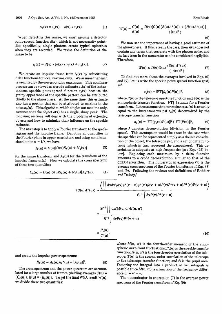
Fig. 1. A, B, Alpha Orionis and C, D, Gamma Orionis for two apodizations applied to the matched filter. A, C, 28 pixels FWHM. B, D, 52pixels FWHM. Frame size is 128 X 128. Observations were made with a 3.8-m telescope at 650 + 1 nm. The image of Gamma Orionis is unre-solved. The images of Alpha Orionis are different by 10% in size (50 frames for each image).
changes for coherence and aperture size accounted for.' 3,' 4
The drawback of this description is that it assumes station-arity of the speckles, true only in the middle of the specklecloud. As mentioned earlier, we model the specklegram as atriple convolution of the object with the telescope (Fig. 2)and with a set of delta functions representing the atmo-sphere. In the different realizations of SAA an effort ismade to proceed in the reverse direction. An estimate of asubset of the (strongest) delta functions is produced, theoriginal specklegram is deconvolved by it, and the result isaveraged over many frames.' From this average it is possi-ble to remove the atmospheric-seeing background (due to
the incompleteness of the subset of the estimate) and thecentral photon spike (due to the Poisson statistics).
Despite the fact that it is possible to remove the seeingbackground and the photon spike from the final image, it ispreferrable to devise a matched filter that would give theright answer directly. Since some information is availableabout the power spectra of the Poisson noise and the seeing,we incorporate it into the matched filter while performingthe iterative data reduction. In the Fourier plane, the maineffect of the seeing background is in the very low frequencies(what is called the "long exposure" 6), whereas the Poissonnoise exists at all frequencies. Thus the total noise power
A _ I i_
Erez Ribak
O
e
2074 J. Opt. Soc. Am. A/Vol. 3, No. 12/December 1986
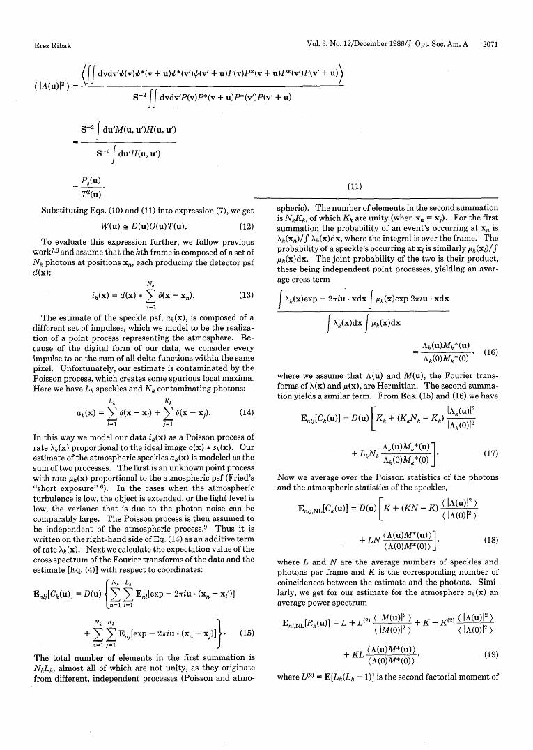
Fig. 2. An image of an unresolved star (Zeta Aquaril A) with the2.28-m telescope at 750 10 nm, showing the (aberrated) telescope-detector psf. Logarithmic intensity scale. Processed from 100frames, about 100 photons each. All figures are with North down,East to the right.
spectrum [Eq. (24)] is accentuated at the very low frequen-cies and constant elsewhere. Dividing the object transformby this power spectrum is equivalent to multiplying it by itsreciprocal, i.e., a bandpass filter.
The combination of a bandpass filter with the object pro-duces an optimum matched filter, which is now applied tothe specklegram. The bandpass filter, convolved with theobject, partially solves both problems (3) and (4) discussedearlier. It smooths out single-photon events below thethreshold level, so that they are not regarded as speckles. Atthe same time it sharpens the wide autocorrelations betweenthe speckles and the object, and as a result the efficiency ofdetecting speckle maxima increases.
4. WIENER FILTER APPROACH
The other approach possible is not to locate the speckles(using the assumption that each one is a replica of the object)but to find the original distribution of the atmosphere, applysome nonlinear process (such as maximum finding) and,continue from there on as with the standard WSA. Asmentioned in Section 3, this calls for a Wiener filter, sincethere is no prior knowledge of the atmospheric distributionand its shape is varying from one realization to the other.Our estimate is now achieved by applying a Wiener filterFW(u) to the current image transform:
Ak(u) = FW(U)Ik(U)
= F(u)D(u)[O(u)Sk(u) + N(u)]. (26)
Actually, we also apply here the nonlinear process of maxi-mum singling in the image plane described above. [If onlylinear processes were applied, we would get rF(u) as the endproduct.] We form the least-squares difference e betweenthe speckle psf and the estimate
e = K! dxls(x) - a(x)12) = K! duIS(u) - A(u)12) (27)
using Parseval's theorem. Combining Eq. (26) with Eq.(27), and assuming that the cross spectrum of the atmo-sphere and the noise average out, we arrive at the requiredfilter' 0 15
F.(U) =O(u)*P8 (u)
(28)D(u)[1O(u) 2 P8 (u) + Pn(u)]
where P,(u) and P,(u) are the speckle and noise power spec-tra, respectively. We make use of the value of the averageimage power spectrum calculated elsewhere 7 8
Pi(u) = ID(u)I2[IO(U) I2P(U) + P"(U)]
to get the final filter
F. (u) [D (u) 0(u)]*P,(u)
(29)
(30)
This is much like the intuitive filter that was mentionedbefore in combination with the matched filter. It tells usthat by using iterative estimates of the object, the imagepower spectrum, and the speckle power spectrum, we cangenerate a valid Wiener filter. The speckle power spectrumand the detector transfer function can be achieved beforethe calculation by observing a point source under similaratmospheric conditions with the same detector. If the at-mospheric conditions are different, then the ratio of thereference speckle power spectrum P6(u) to the actual onewill differ mainly in the u = r/X regime.' 6 At higher fre-quencies this ratio will tend toward the ratio of the numbersof speckles for the two cases. So unless the object has a greatinformation content at low frequencies, it is safe to use areference speckle power spectrum. If not, a theoretical esti-mate can be made from the image power spectrum, which isactually the matched-filter method discussed above.
5. APPLICATION AND RESULTS
The data processed were produced on the Kitt Peak Nation-al Observatory 3.8-m telescope and the Steward Observatory2.3-m telescope. The detector used was the Steward Obser-yatory speckle camera,17 with television frames digitized to a128 X 128 format with 8-bit integers. Some of the data werephoton limited (see Figs. 1-3).
The first reductions were done in image space, in an ap-proach similar to the simple SAA. An estimate of the object,usually a Gaussian, was slid along and multiplied with theframe (image-plane correlation). At the same time asmoothing function (a wider Gaussian) was correlated withthe frame. Every local maximum that was higher in thefiltered frame than in the smoothed frame was counted as aspeckle, and the corresponding part in the original speckle-gram was added to the running sum. With bright objects,where the photon noise is negligible, the result appearedafter only one frame. The computational efficiency of thismethod was rather low, especially for larger objects, whichdemanded many multiplications. The advantage was thatonly one full frame resided in memory at any time.
The process was then repeated in the Fourier plane (Fig.4). The cycle for each frame is as follows: (a) read frame in,(b) transform the frame, (c) multiply the frame transform
Erez Ribak
Vol. 3, No. 12/December 1986/J. Opt. Soc. Am. A 2075
-- U
.o -,0**o. * I
I 9.0I. I.
* 0Ii. h
0.
4* e
Ig
- .'
: * . _
A '
0
. I
I I
i. ° <3
I . , R-o ' 8r. . ' , ,
9
e 0
.o * .
Vr I a
Q ie ...
0s %0 I I I' *
a°It
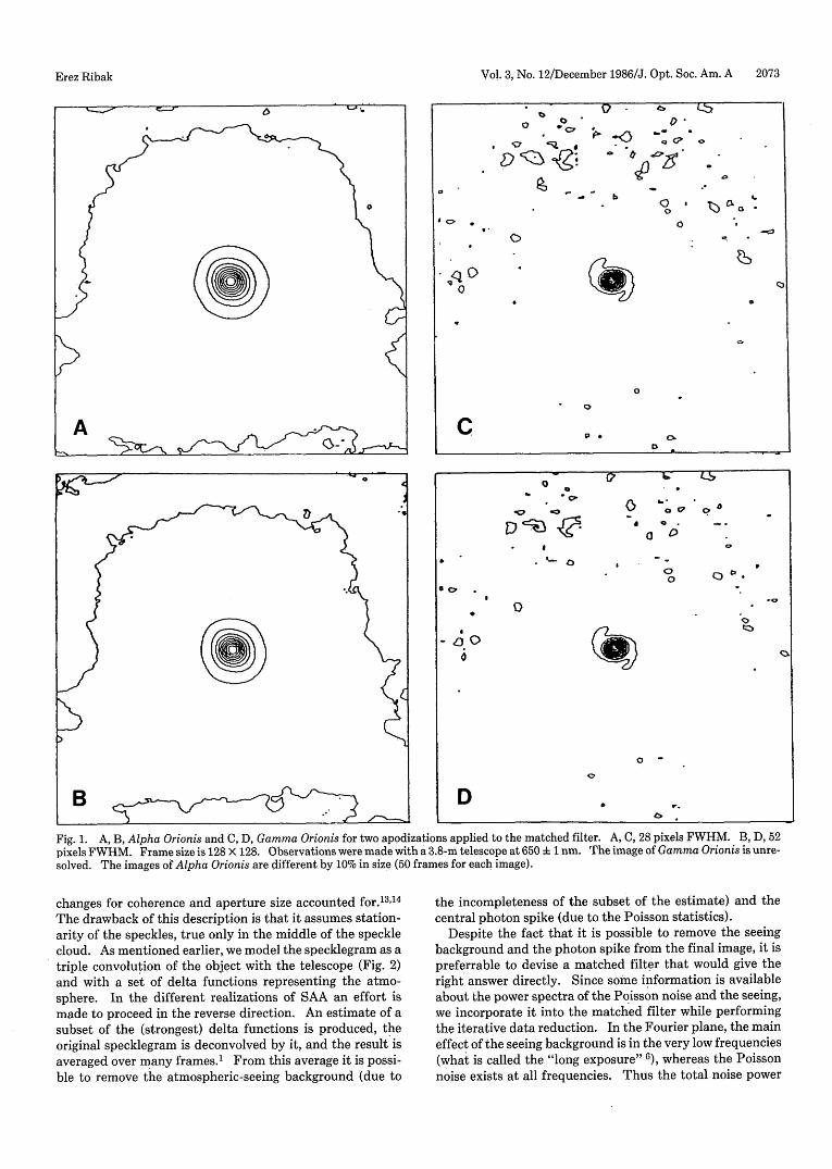
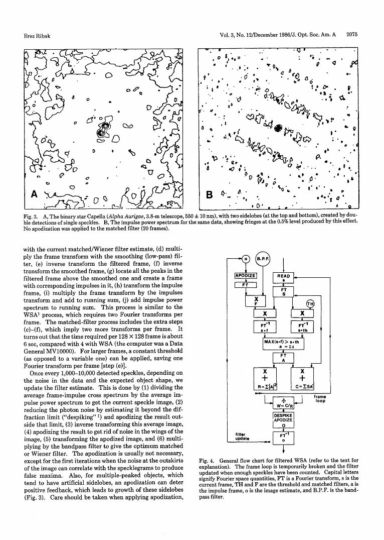
Fig. 3. A, The binary star Capella (Alpha Aurigae, 3.8-m telescope, 550 f 10 nm), with two sidelobes (at the top and bottom), created by dou-ble detections of single speckles. B, The impulse power spectrum for the same data, showing fringes at the 0.5% level produced by this effect.No apodization was applied to the matched filter (20 frames).
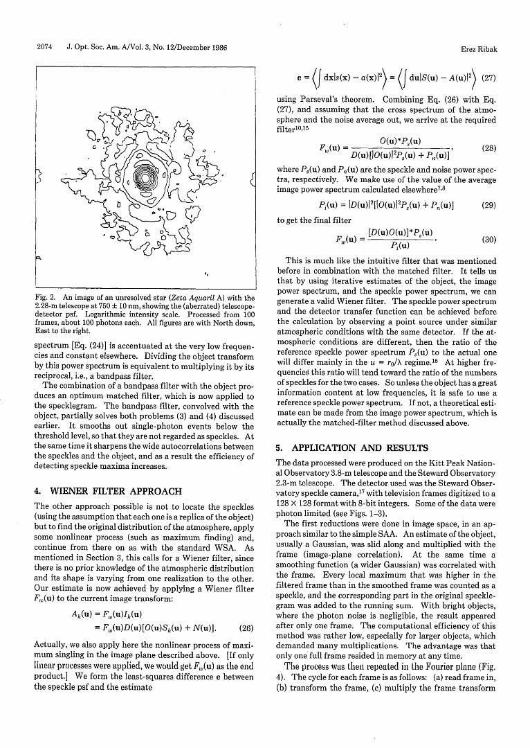
with the current matched/Wiener filter estimate, (d) multi-ply the frame transform with the smoothing (low-pass) fil-ter, (e) inverse transform the filtered frame, (f) inversetransform the smoothed frame, (g) locate all the peaks in thefiltered frame above the smoothed one and create a framewith corresponding impulses in it, (h) transform the impulseframe, (i) multiply the frame transform by the impulsestransform and add to running sum, (j) add impulse powerspectrum to running sum. This process is similar to theWSA' process, which requires two Fourier transforms perframe. The matched-filter process includes the extra steps(c)-(f), which imply two more transforms per frame. Itturns out that the time required per 128 X 128 frame is about6 sec, compared with 4 with WSA (the computer was a DataGeneral MV10000). For larger frames, a constant threshold(as opposed to a variable one) can be applied, saving oneFourier transform per frame [step (e)].
Once every 1,000-10,000 detected speckles, depending onthe noise in the data and the expected object shape, weupdate the filter estimate. This is done by (1) dividing theaverage frame-impulse cross spectrum by the average im-pulse power spectrum to get the current speckle image, (2)reducing the photon noise by estimating it beyond the dif-fraction limit ("despiking" ') and apodizing the result out-side that limit, (3) inverse transforming this average image,(4) apodizing the result to get rid of noise in the wings of theimage, (5) transforming the apodized image, and (6) multi-plying by the bandpass filter to give the optimum matchedor Wiener filter. The apodization is usually not necessary,except for the first iterations when the noise at the outskirtsof the image can correlate with the specklegrams to producefalse maxima. Also, for multiple-peaked objects, whichtend to have artificial sidelobes, an apodization can deterpositive feedback, which leads to growth of these sidelobes(Fig. 3). Care should be taken when applying apodization,
Fig. 4. General flow chart for filtered WSA (refer to the text forexplanation). The frame loop is temporarily broken and the filterupdated when enough speckles have been counted. Capital letterssignify Fourier space quantities, FT is a Fourier transform, s is thecurrent frame, TH and F are the threshold and matched filters, a isthe impulse frame, o is the image estimate, and B.P.F. is the band-pass filter.
9
I'.
0.
boa 0 p4 ; 0
.
a
a
. 9
.. . v
0
O 0
o .0
8a
Erez Ribak
- -- 0. .
o;
e,
.
'QW ItI S
t : .

2076 J. Opt. Soc. Am. A/Vol. 3, No. 12/December 1986
since the apodizing bell should be larger than the objectextent (Fig. 1).
The main deficiencies of the current implementation ofthe matched/Wiener-filter method are the following: (1)complicated calculations requiring much computer time arenecessary, (2) for extended objects, too few speckles arefound, which lead to an extended seeing background,' 2"13 (3)for multiple-peak objects, great care must be taken whenbuilding the filter lest the filtered frame have more than onemaximum per speckle and thus lose the advantage oversimple SAA methods.
ACKNOWLEDGMENTS
I would like to thank J. C. Christou, E. K. Hege, F. Roddier,and J. D. Freeman for many thought-provoking conversa-tions and for astronomical data. I would also like to ac-knowledge the support of the Weizmann Fund. Some of theobservations reported here were obtained at Kitt Peak Na-tional Observatory, a division of the National Optical As-tronomy Observatories, operated by the Association of Uni-versities for Research in Astronomy, Inc., under contractwith the National Science Foundation.
The author was formerly with the Steward Observatory,University of Arizona, Tucson, Arizona 85721.
REFERENCES
1. J. C. Christou, E. K. Hege, J. D. Freeman, and E. Ribak, "A self-calibrating shift-and-add technique for speckle imaging," J.Opt. Soc. Am. A 3, 204-209 (1986); "Images from astronomicalspeckle data: weighted shift-and-add analysis," in Interna-tional Conference on Speckle, H. Arsenault, ed., Proc. Soc.Photo-Opt. Instrum. Eng. 556, 255-262 (1985).
2. G. P. Weigelt and B. Wirnitzer, "Image reconstruction by thespeckle masking method," Opt. Lett. 8, 389-391 (1983).
3. R. H. T. Bates, "Astronomical speckle imaging," Phys. Rep. 90,203-297 (1982).
4. R. H. T. Bates and F. W. Cady, "Towards true imaging by wide-band speckle interferometry," Opt. Commun. 32, 365-369(1980).
5. C. R. Lynds, S. P. Worden, and J. W. Harvey, "Digital image
reconstruction applied to Alpha Orionis," Astrophys. J. 207,174-179 (1976).
6. F. Roddier, "The effects of atmospheric turbulence in opticalastronomy," in Progress in Optics XIX, E. Wolf, ed. (North-Holland, Amsterdam, 1981), pp. 281-376; J. C. Dainty, "Stellarspeckle interferometry," in Laser Speckle and Related Phe-nomena, 2nd ed., J. C. Dainty, ed. (Springer-Verlag, Berlin,1983).
7. J. W. Goodman and J. F. Belsher, "Photon limited images andtheir restoration," RADC-TR-76-50, March 1976; ARPA order#2646 (Rome Air Development Center, Griffiss AFB, N.Y.);"Fundamental limitations in linear invariant restoration of at-mospherically degraded images," in Seminar on Imagingthrough the Atmosphere, J. C. Wyant, ed., Proc. Soc. Photo-Opt. Instrum. Eng. 75, 141-154 (1976).
8. J. C. Dainty and A. H. Greenaway, "Estimation of spatial powerspectra in speckle interferometry," J. Opt. Soc. Am. 69,786-790(1979).
9. B. Saleh, Photoelectron Statistics (Springer-Verlag, Berlin,1978), Sec. 5.2.9.
10. K. R. Castleman, Digital Image Processing (Prentice-Hall, En-glewood Cliffs, N.J., 1979).
11. E. Ribak, E. K. Hege, and J. C. Christou, "Identification ofspeckles by matched filtering," Bull. Am. Astron. Soc. 16, 885(1984); "Use of matched filtering to identify speckle locations,"in International Conference on Speckle, H. Arsenault, ed.,Proc. Soc. Photo-Opt. Instrum. Eng. 556, 196-201 (1985).
12. A. M. Sinton, R. A. Minard, and R. H. T. Bates, "Generalizationof shift-and-add imaging," in International Conference onSpeckle, H. Arsenault, ed., Proc. Soc. Photo-Opt. Instrum. Eng.556, 263-269 (1985).
13. B. R. Hunt, W. R. Fright, and R. H. T. Bates, "Analysis of theshift and add method for imaging through turbulent media," J.Opt. Soc. Am. 73, 456-465 (1983).
14. J. D. Freeman, E. Ribak, J. C. Christou, and E. K. Hege, "Statis-tical analysis of the weighted shift-and-add image reconstruc-tion technique," in International Conference on Speckle, H.Arsenault, ed., Proc. Soc. Photo-Opt. Instrum. Eng. 556, 279-283 (1985).
15. B. R. Frieden, Probability, Statistical Optics, and Data Testing(Springer-Verlag, Berlin, 1983).
16. J. C. Christou, A. Y. S. Cheng, E. K. Hege, and C. Roddier,"Seeing calibration of optical astronomical speckle interfero-metric data," Astron. J. 90, 2644-2651 (1985).
17. E. K. Hege, E. N. Hubbard, P. A. Strittmatter, and W. J. Cocke,"The Steward Observatory speckle interferometry system,"Opt. Acta 29, 701-715 (1982).
Erez Ribak