astm - thin plate weirs.pdf
TRANSCRIPT
7/21/2019 astm - thin plate weirs.pdf
http://slidepdf.com/reader/full/astm-thin-plate-weirspdf 1/6
Weirs and Flumes
SKRENTER, R. (1969, 1982)
Flume
Weir Flow Sheet Symbol
Types Open-channel flow can be measured by detecting level in front of primaries. Bubblers,
capacitance, float, hydrostatic, and ultrasonic devices are used as level sensors. Open-
channel flows can also be measured without primaries by calculating flow from depth
and velocity using ultrasonic and magnetic sensors.
Operating Conditions Atmospheric
Applications Waste or irrigation water flows in open channels
Flow Range From 1 GPM (3.78 l/m), no upper limit
Rangeability Most devices provide 75:1; V-notch weirs can reach up to 500:1
Inaccuracy Laboratory devices: 2 to 3% of full scale
Field installations: 5 to 10% of full scale
Costs Primaries used in pipe inserts cost less than $1000. A 6 x 6 x 0.12 -in. V-notch weir
costs about $1500, and a 48-in. (1.22-m) one costs about $5000. Primaries for
irrigation applications are usually field-fabricated. Manual depth sensors can be
obtained for $300; local bubbler or float indicators for $750 to $1500; and program-
mable, transmitting, capacitance, ultrasonic, or bubbler units from $2000 to $3000.
Open-channel flowmeters calculating flow (based on depth and velocity) range from
$5000 to over $10,000.
Partial List of Suppliers ABB Automation, Instrumentation Division (www.abb.com/us/instrumentation)
(primaries)
Badger Meter Inc. (www.badgermeter.com) (Parshall or manhole flume, ultrasonic
and open-channel computing)
Endress+Hauser Inc. (www.us.endress.com) (ultrasonic and capacitance)
Fischer Controls Int. (ultrasonic)
Flow Technology Inc. (www.ftimeters.com)
GLI International (www.gliint.com)
Hays Cleveland (www.hayscleveland.com)
Kay-Ray/Sensall Inc. (www.thermo.com) (ultrasonic)
Manning Environmental Corp. (www.manning-enviro.com) (primaries)
Marsh-McBirney Inc. (www.marsh-mcbirney.com) (electromagnetic)
Milltronics Inc. (www.milltronics.com) (ultrasonic)
Montedoro-Whitney Corp. (open-channel flow by ultrasonics)
MSR Magmeter Mfg. Ltd. (www.magmeter.com) (robotic magmeter probe for open
channel)
Princo Instruments Inc. (www.princoinstruments.com) (capacitance)
Robertshaw Ind.
Royce Instrument Corp.
Sponsler Co. (www.sponsler.com)
Thermal Instrument Co. (www.thermalinstrument.com)
Thermo Polysonics (www.thermopolysonics.com)
© ASTM D – 5254 – 92(2001)
AMERICAN SOCIETY FOR TESTING AND MATERIALS
ASTM D5254 – 92 (2001). Standard Test Method for Open Channelflow Measurement of Water with Thin – Plate Weirs

7/21/2019 astm - thin plate weirs.pdf
http://slidepdf.com/reader/full/astm-thin-plate-weirspdf 2/6
WEIRS
Weirs are apertures in the top of a dam, across a channel
through which flows the liquid to be measured (Figure 2.31a).
The aperture may be rectangular (Figure 2.31b), trapezoidal
(Figure 2.31c), or V-notch (Figure 2.31d). The special case
of a trapezoidal weir with side slopes of 1:4 (Figure 2.31c)is known as a Cippoletti weir ; this form leads to a simplified
flow calculation. V-notch weirs generally have a notch angle
from 30 to 90°, depending on required flow capacity.Heads less than0.1 ft (30 mm) for minimum measured flow or
more than 1.0 ft (300-mm) for maximum flow are generally to
be avoided,
Drawdown
Nappe
Angle of notch (θ)
FIG. 2.31d
V-notch weir.
Flow
H
Aeration
Under Nappe
FIG. 2.31a
Flow over a weir.
FIG. 2.31e
End Contractions
L
Crest
Bottom Q = 3.33 (L−0.2H)H3/2
Contraction
FIG. 2.31b
Rectangular weir.
4
Crest
L
Q = 3.367 LH3/2
FIG. 2.31c
Cippoletti (trapezoidal) weir.
Weir box.
although a 1.25-ft (380-mm) head can be tolerated under favor-
able conditions. These limits are easily met by practical design,
given that a 45° V-notch will measure a minimum flow of
0.58, whereas the maximum value for a rectangular
or trapezoidal weir is limited only by practical crest length.
Standard thin plate v-notch weirs widely used by the
ASTM are 6x6x0.12 inch in size which is primarily used for
smaller flows and small-scale laboratory tests . A 45° V-notch
weir has a practically constant coefficient from 0.58 to 0.62.
For notch angle up to 90°, flow varies as the tangent of half
the notch angle. Notch angle exceeding 90° is not
recommended.
Rectangular or Cippoletti weirs are used for larger flows.A rectangular weir with a crest 2 ft (0.6 m) long develops a
head of about 0.2 ft (60 mm) for 250 GPM (946 l/min) and
1.0 ft (305 mm) for 2700 GPM (10,221 l/min). For this weir,
flow is directly proportional to crest length and to the three-
halves power of the head.
The weir plate may be located in a dam in a natural channel
or in a weir box (Figure 2.31e). The stilling basin ahead of the
weir should be large enough so that the upstream velocity does
not exceed 0.33 ft/sec (0.01 m/sec). Width and depth immedi-
ately ahead of the weir should be sufficient so that the wall
effect of the bottom and sides of the channel has negligible
© ASTM D – 5254 – 92(2001)
Q = 8/15 √2g tan (Θ/2) H5/2
7/21/2019 astm - thin plate weirs.pdf
http://slidepdf.com/reader/full/astm-thin-plate-weirspdf 3/6
effect on the pattern of flow through the notch. It is important
that the flow break clear from the sharp edge of the notch with
an air pocket maintained immediately beyond and below the
weir plate. The channel downstream from the weir must be
sufficiently wide and deep so that, at maximum flow, there is
ample clearance between flow through the notch to downstream
liquid level so that this air pocket is maintained (Figure 2.31a).
The upstream edge of the weir should be sharp and straight. It
is usual practice to bevel the downstream edge of the weir at
45° to about a 1/32-in. (0.8-mm) edge. For rectangular and
Cippoletti weirs, the crest must be carefully leveled.
Accuracy of the relation between flow and head (level)
to ±2% is attainable, based on the dimensions of the primary
device. Reference 1 gives full data on installation and oper-
ation of weirs.
The following equations establish the relationships
between flow and measured head, provided that the installa-
tion and operation of the weir are as recommended in this
section and also in the cited references.
For a V-notch weir
o o
Converging Throat Diverging
Section Section Section
Plan
Water Surface Submerged
Operation
Flow
Level
Floor Normal Operation
Section O-O
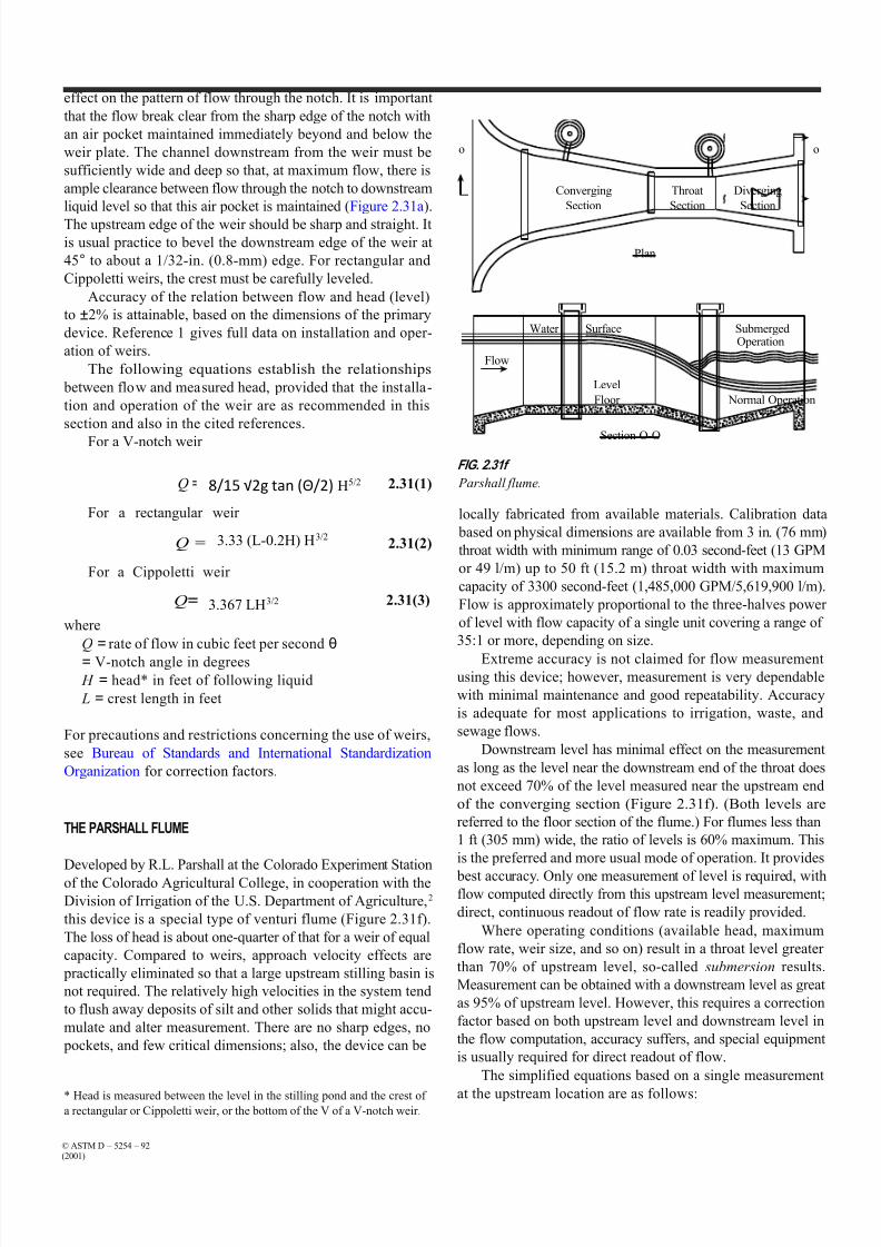
FIG. 2.31f
Q =
For a rectangular weir
Q =
For a Cippoletti weir
Q=
where
2
θ H 25 2.31(1)
2.31(2)
2.31(3)
Parshall flume.
locally fabricated from available materials. Calibration data
based on physical dimensions are available from 3 in. (76 mm)
throat width with minimum range of 0.03 second-feet (13 GPM
or 49 l/m) up to 50 ft (15.2 m) throat width with maximum
capacity of 3300 second-feet (1,485,000 GPM/5,619,900 l/m).
Flow is approximately proportional to the three-halves power
of level with flow capacity of a single unit covering a range of
Q = rate of flow in cubic feet per second θ
= V-notch angle in degrees
H = head* in feet of following liquid
L = crest length in feet
For precautions and restrictions concerning the use of weirs,
see Bureau of Standards and International Standardization
Organization for correction factors.
THE PARSHALL FLUME
Developed by R.L. Parshall at the Colorado Experiment Station
of the Colorado Agricultural College, in cooperation with the
Division of Irrigation of the U.S. Department of Agriculture,2
this device is a special type of venturi flume (Figure 2.31f).
The loss of head is about one-quarter of that for a weir of equal
capacity. Compared to weirs, approach velocity effects are
practically eliminated so that a large upstream stilling basin is
not required. The relatively high velocities in the system tend
to flush away deposits of silt and other solids that might accu-
mulate and alter measurement. There are no sharp edges, no
pockets, and few critical dimensions; also, the device can be
* Head is measured between the level in the stilling pond and the crest ofa rectangular or Cippoletti weir, or the bottom of the V of a V-notch weir.
35:1 or more, depending on size.
Extreme accuracy is not claimed for flow measurementusing this device; however, measurement is very dependable
with minimal maintenance and good repeatability. Accuracy
is adequate for most applications to irrigation, waste, and
sewage flows.
Downstream level has minimal effect on the measurement
as long as the level near the downstream end of the throat does
not exceed 70% of the level measured near the upstream end
of the converging section (Figure 2.31f). (Both levels are
referred to the floor section of the flume.) For flumes less than
1 ft (305 mm) wide, the ratio of levels is 60% maximum. This
is the preferred and more usual mode of operation. It provides
best accuracy. Only one measurement of level is required, withflow computed directly from this upstream level measurement;
direct, continuous readout of flow rate is readily provided.
Where operating conditions (available head, maximum
flow rate, weir size, and so on) result in a throat level greater
than 70% of upstream level, so-called submersion results.
Measurement can be obtained with a downstream level as great
as 95% of upstream level. However, this requires a correction
factor based on both upstream level and downstream level in
the flow computation, accuracy suffers, and special equipment
is usually required for direct readout of flow.
The simplified equations based on a single measurement
at the upstream location are as follows:
© ASTM D – 5254 – 92(2001)
3.33 (L-0.2H) H3/2
3.367 LH3/2
8/15 √2g tan (Θ/2) H5/2

7/21/2019 astm - thin plate weirs.pdf
http://slidepdf.com/reader/full/astm-thin-plate-weirspdf 4/6
397 LH 1547
412 LH 158
410 LH 153
TABLE 2.31h
Dimensions and Capacities of One-Piece Parshall Flumes*†
Free Flow (GPM)
Throat Width Depth (inches) Length Weight (pounds) Minimum Maximum
2 in. 12 2 ft, 6.5 in. 35 9.0 210
3 in. 24 3 ft, 0 in. 40 13.5 494
6 in. 24 5 ft, 0 in. 100 22.4 1750
9 in. 30 5 ft, 4 in. 130 40.4 3950
12 in. 36 9 ft, 4.875 in. 280 157.0 7225
18 in. 36 9 ft, 7.875 in. 305 228.9 11,040
24 in. 36 9 ft, 10.875 in. 330 296.2 14,855
3 ft, 0 in. 36 10 ft, 4.075 in. 385 435.3 22,619
4 ft, 0 in. 36 10 ft, 10.375 in. 450 565.5 30,473
5 ft, 0 in. 36 11 ft, 10.25 in. 515 996.3 38,417
6 ft, 0 in. 36 11 ft, 10.375 in. 575 1180.3 46,450
7 ft, 0 in. 36 12 ft, 4.25 in. 650 1831.1 54,484
8 ft, 0 in. 36 12 ft, 10.125 in. 730 2073.5 62,607
*Units in table can be converted using 1 in. = 25.4 mm, 1 lb. = 0.45 kg; 1 in. H2O = 249 Pa; 1 GPM = 3.785 l/min.
†Courtesy of ABB Inc.
For L = 0.25 ft,
Q= 2.31(4)
For L = 0.5 ft,
Q= 2.31(5)
For L = 0.75 ft,
Q= 2.31(6)
For L = 1 to 8 ft,
6
Q=(2.5 +3 69 L) H
1. 2.31(8)
where
L = width of throat section in feet
Q = volume flow rate in cubic feet per second
H = head in feet*
Parshall flumes are available in plastic construction. One
variation of the plastic units is the nested, dual-range config-
uration in which two flumes are nested inside each other.This configuration is used in installations where the start-up
conditions are substantially lower than the final operating
flow rates (Figure 2.31g). With these units, the flow initially
passes through the inner flume; then, when the flow exceeds
its capacity, the inner flume is removed while the outer flume
* H (head) is measured at a designated point in the upstream converging
section, referred to the level floor of this section.
FIG. 2.31g
Dual-range Parshall flume. (Courtesy of ABB - Fischer & Porter Co.)
remains in place permanently. Dimensions of fiberglass-
reinforced resin Parshall flumes are given in Table 2.31h.
THE PALMER BOWLUS FLUME
Palmer-Bowlus flumes provide the advantages of rounded bot-
toms and relatively small size. Compared with other flumes,
this makes for easier installation in pipe inverts, ends, and
sewer manholes. They also have a smaller head change vs.
© ASTM D – 5254 – 92(2001)

7/21/2019 astm - thin plate weirs.pdf
http://slidepdf.com/reader/full/astm-thin-plate-weirspdf 5/6
FIG. 2.31j
Volumetric flow computer measures depth and velocity in open chan-
nel and does not require a primary device. (Courtesy of Montedoro-
Whitney Corp.)
FIG. 2.31i
Flume insert elements. (Courtesy of Manning Environmental Corp.)
flow, and their dimensions are scalable to throat width, which
makes rating of off-size flumes possible. A disadvantage is that
the throat is raised; therefore, the possibility exists for upstream
silt deposition at low flows. Reference 3 provides data on this.
These flumes are available for installation in existing
round pipe using the type of insert shown in Figure 2.31i.
THE KENNISON NOZZLE, PARABOLIC FLUME, AND
LEOPOLD LAGCO FLUME
These are typical proprietary products that were designed
primarily for end-of-pipe flow measurement of waste, sew-
age, and the like, where the liquid flow to be measured
emerges from a cylindrical pipe or conduit that usually is not
completely full of liquid. All are designed to flush solids
through the device without accumulations and to allow acces-
sibility for inspection and cleaning if necessary.
These devices develop heads that are a function of flow rate.
In the Kennison nozzle, head is almost linear with flow above
10% of maximum flow rate. Accuracy is stated as 2% in this
range. For the parabolic flume and the Leopold Lagco flume,flow varies approximately as the three-halves power of head.
These devices are available in medium to large sizes.
Details as to structure, application, and characteristics are
available from the manufacturers.
DETECTORS FOR OPEN-CHANNEL SENSORS
The level rise generated by flumes or weirs can be measured by
nearly any of the level detectors described in Chapter 3, including
such simple devices as the air or nitrogen bubblers (Section 3.2).
I f v
Q = Flow
Example of a
Velocity Profile
FIG. 2.31k
Robot-operated magnetic flow meter probe sensor is used to compute
channel flow. (Courtesy of MSR Magmeter Mfg. Ltd.)
It is also possible to detect the flow in open channels
without the use of flumes, weirs, or any other primary devices.
One such design computes flow in round pipes or open chan-
nels by ultrasonically measuring the depth, calculating the flow-
ing cross-sectional area on that basis, and multiplying the area
by the velocity to obtain volumetric flow (Figure 2.31j).
Another open-channel flowmeter that does not need a
primary element uses a robot-operated magnetic flowmeter
probe to scan the velocity profile in the open channel (Figure
2.31k). In this design, the computer algorithm calculates and
© ASTM D – 5254 – 92(2001)

7/21/2019 astm - thin plate weirs.pdf
http://slidepdf.com/reader/full/astm-thin-plate-weirspdf 6/6
separately adds up the flow segments through each slice of the velocity profile as the velocity sensor moves down to the bottom
of the channel.