astm - f330
DESCRIPTION
Requirements for Bird Strike Justification on AircraftTRANSCRIPT
Designation: F 330 – 89 (Reapproved 2004)
Standard Test Method forBird Impact Testing of Aerospace Transparent Enclosures 1
This standard is issued under the fixed designation F 330; the number immediately following the designation indicates the year oforiginal adoption or, in the case of revision, the year of last revision. A number in parentheses indicates the year of last reapproval. Asuperscript epsilon (e) indicates an editorial change since the last revision or reapproval.
This standard has been approved for use by agencies of the Department of Defense.
1. Scope
1.1 This test method covers conducting bird impact testsunder a standard set of conditions by firing a packaged bird ata stationary transparency mounted in a support structure.
1.2 The values stated in inch-pound units are to be regardedas the standard. The values given in parentheses are forinformation only.
1.3 This standard does not purport to address all of thesafety concerns, if any, associated with its use. It is theresponsibility of the user of this standard to establish appro-priate safety and health practices and determine the applica-bility of regulatory limitations prior to use.For specific hazardstatements, see Section 8.
2. Terminology
2.1 Definitions:2.1.1 bird—the carcass that is used to impact the test article.2.1.2 bird package—the bird and container that encases the
bird to prevent disintegration enroute to target.2.1.3 gun—the device that propels the bird toward the
target.2.1.4 sabot—the container that is used to adapt the bird
package to the gun barrel.2.1.5 stripper—the device that stops the sabot at the end of
the gun barrel so that only the bird and package exits from thebarrel.
2.1.6 test article—the transparency and supporting struc-ture.
3. Summary of Test Method
3.1 This test method employs a smooth-bore bird gun thatfires a chicken carcass so that it impacts a stationary aerospacetransparency mounted in a supporting structure.
3.2 The specific parameters described by this test methodare:
3.2.1 Bird weight and condition,
3.2.2 Bird velocity, and3.2.3 Instrumentation.
4. Significance and Use
4.1 This test method may be used for: bird impact testing ofaircraft crew compartment transparencies and supporting struc-ture to verify the design; compilation of test data for use inverification of future transparency and supporting structuredesign and analytical methods; and comparative evaluation ofmaterials.
5. Apparatus
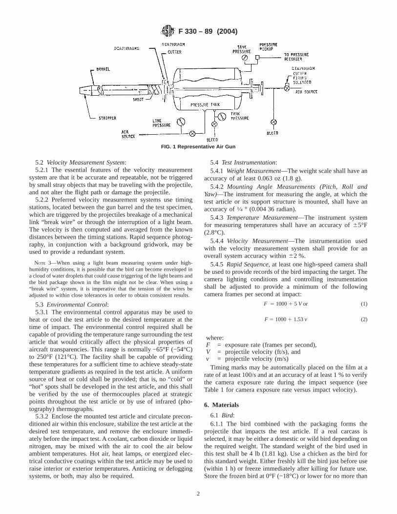
5.1 Gun, compressed gas, conforming in principle to Fig. 1,comprising:
5.1.1 Pressure Tank, of capacity and working pressure asdiscussed in Note 1.
NOTE 1—A gun capable of propelling a 4-lb (1.81-kg) bird in excess of650 knots (334 m/s) has a barrel 60 ft (18.3 m) long, bore of 6 in. (153mm), and a pressure tank volume of 30 ft3 (0.849 m3) with an allowableworking pressure of 250 psi (1.7253 106 Pa).
5.1.2 Release Mechanism, comprised of a firing solenoid,diaphragm, and a cutter. Upon initiation of the firing sequence,the release mechanism allows the compressed gas stored in thepressure tank to flow rapidly into the gun barrel and propel theprojectile.
NOTE 2—The most common designs normally use either one or twodiaphragms in the release mechanism. In the single diaphragm design, thediaphragm is mechanically ruptured upon firing (see Fig. 1). In the dualdiaphragm system, pressurized gas between the two pressurized gasdiaphragms is bled to initiate firing by allowing the stored gas to bursteach diaphragm in rapid succession.
5.1.3 Barrel (Launch Tube), a smooth bore tube that guidesthe packaged bird (and sabot if used) during its acceleration bythe expanding air from the pressure tank. The bore and lengthof the barrel is chosen both to accommodate the largest of theprojectiles to be used and for the overall performance require-ments of the gun.
5.1.4 Sabot Strippermay be mounted at the end of thelauncher tube. The purpose of the sabot stripper is to arrest ordeflect the sabot, allowing only the packaged bird to impact thetest article.
1 This test method is under the jurisdiction of ASTM Committee F07 onAerospace and Aircraft and is the direct responsibility of Subcommittee F07.08 onTransparent Enclosures and Materials.
Current edition approved Oct. 1, 2004. Published October 2004. Originallyapproved in 1979. Last previous edition approved in 1999 as F 330 – 89 (1999).
1
Copyright © ASTM International, 100 Barr Harbor Drive, PO Box C700, West Conshohocken, PA 19428-2959, United States.
5.2 Velocity Measurement System:5.2.1 The essential features of the velocity measurement
system are that it be accurate and repeatable, not be triggeredby small stray objects that may be traveling with the projectile,and not alter the flight path or damage the projectile.
5.2.2 Preferred velocity measurement systems use timingstations, located between the gun barrel and the test specimen,which are triggered by the projectiles breakage of a mechanicallink “break wire” or through the interruption of a light beam.The velocity is then computed and averaged from the knowndistances between the timing stations. Rapid sequence photog-raphy, in conjunction with a background gridwork, may beused to provide a redundant system.
NOTE 3—When using a light beam measuring system under high-humidity conditions, it is possible that the bird can become enveloped ina cloud of water droplets that could cause triggering of the light beams andthe bird package shown in the film might not be clear. When using a“break wire” system, it is imperative that the tension of the wires beadjusted to within close tolerances in order to obtain consistent results.
5.3 Environmental Control:5.3.1 The environmental control apparatus may be used to
heat or cool the test article to the desired temperature at thetime of impact. The environmental control required shall becapable of providing the temperature range surrounding the testarticle that would critically affect the physical properties ofaircraft transparencies. This range is normally −65°F (−54°C)to 250°F (121°C). The facility shall be capable of providingthese temperatures for a sufficient time to achieve steady-statetemperature gradients as required in the test article. A uniformsource of heat or cold shall be provided; that is, no “cold” or“hot” spots shall be developed in the test article, and this shallbe verified by the use of thermocouples placed at strategicpoints throughout the test article or by use of infrared (pho-tography) thermographs.
5.3.2 Enclose the mounted test article and circulate precon-ditioned air within this enclosure, stabilize the test article at thedesired test temperature, and remove the enclosure immedi-ately before the impact test. A coolant, carbon dioxide or liquidnitrogen, may be mixed with the air to cool the air belowambient temperatures. Hot air, heat lamps, or energized elec-trical conductive coatings within the test article may be used toraise interior or exterior temperatures. Antiicing or defoggingsystems, or both, may also be required.
5.4 Test Instrumentation:5.4.1 Weight Measurement—The weight scale shall have an
accuracy of at least 0.063 oz (1.8 g).5.4.2 Mounting Angle Measurements (Pitch, Roll and
Yaw)—The instrument for measuring the angle, at which thetest article or its support structure is mounted, shall have anaccuracy of1⁄4 ° (0.004 36 radian).
5.4.3 Temperature Measurement—The instrument systemfor measuring temperatures shall have an accuracy of65°F(2.8°C).
5.4.4 Velocity Measurement—The instrumentation usedwith the velocity measurement system shall provide for anoverall system accuracy within62 %.
5.4.5 Rapid Sequence, at least one high-speed camera shallbe used to provide records of the bird impacting the target. Thecamera lighting conditions and controlling instrumentationshall be adjusted to provide a minimum of the followingcamera frames per second at impact:
F 5 10001 5 V or (1)
F 5 10001 1.53v (2)
where:F = exposure rate (frames per second),V = projectile velocity (ft/s), andv = projectile velocity (m/s)
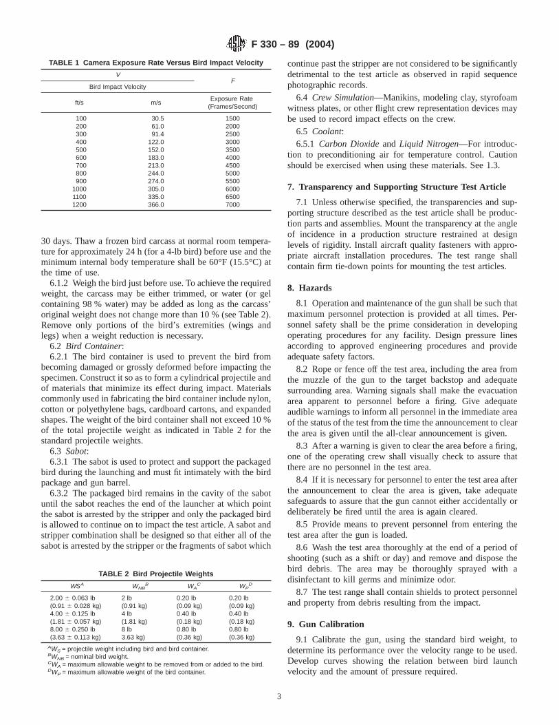
Timing marks may be automatically placed on the film at arate of at least 100/s and at an accuracy of at least 1 % to verifythe camera exposure rate during the impact sequence (seeTable 1 for camera exposure rate versus impact velocity).
6. Materials
6.1 Bird:6.1.1 The bird combined with the packaging forms the
projectile that impacts the test article. If a real carcass isselected, it may be either a domestic or wild bird depending onthe required weight. The standard weight of the bird used inthis test shall be 4 lb (1.81 kg). Use a chicken as the bird forthis standard weight. Either freshly kill the bird just before use(within 1 h) or freeze immediately after killing for future use.Store the frozen bird at 0°F (−18°C) or lower for no more than
FIG. 1 Representative Air Gun
F 330 – 89 (2004)
2
30 days. Thaw a frozen bird carcass at normal room tempera-ture for approximately 24 h (for a 4-lb bird) before use and theminimum internal body temperature shall be 60°F (15.5°C) atthe time of use.
6.1.2 Weigh the bird just before use. To achieve the requiredweight, the carcass may be either trimmed, or water (or gelcontaining 98 % water) may be added as long as the carcass’original weight does not change more than 10 % (see Table 2).Remove only portions of the bird’s extremities (wings andlegs) when a weight reduction is necessary.
6.2 Bird Container:6.2.1 The bird container is used to prevent the bird from
becoming damaged or grossly deformed before impacting thespecimen. Construct it so as to form a cylindrical projectile andof materials that minimize its effect during impact. Materialscommonly used in fabricating the bird container include nylon,cotton or polyethylene bags, cardboard cartons, and expandedshapes. The weight of the bird container shall not exceed 10 %of the total projectile weight as indicated in Table 2 for thestandard projectile weights.
6.3 Sabot:6.3.1 The sabot is used to protect and support the packaged
bird during the launching and must fit intimately with the birdpackage and gun barrel.
6.3.2 The packaged bird remains in the cavity of the sabotuntil the sabot reaches the end of the launcher at which pointthe sabot is arrested by the stripper and only the packaged birdis allowed to continue on to impact the test article. A sabot andstripper combination shall be designed so that either all of thesabot is arrested by the stripper or the fragments of sabot which
continue past the stripper are not considered to be significantlydetrimental to the test article as observed in rapid sequencephotographic records.
6.4 Crew Simulation—Manikins, modeling clay, styrofoamwitness plates, or other flight crew representation devices maybe used to record impact effects on the crew.
6.5 Coolant:6.5.1 Carbon Dioxideand Liquid Nitrogen—For introduc-
tion to preconditioning air for temperature control. Cautionshould be exercised when using these materials. See 1.3.
7. Transparency and Supporting Structure Test Article
7.1 Unless otherwise specified, the transparencies and sup-porting structure described as the test article shall be produc-tion parts and assemblies. Mount the transparency at the angleof incidence in a production structure restrained at designlevels of rigidity. Install aircraft quality fasteners with appro-priate aircraft installation procedures. The test range shallcontain firm tie-down points for mounting the test articles.
8. Hazards
8.1 Operation and maintenance of the gun shall be such thatmaximum personnel protection is provided at all times. Per-sonnel safety shall be the prime consideration in developingoperating procedures for any facility. Design pressure linesaccording to approved engineering procedures and provideadequate safety factors.
8.2 Rope or fence off the test area, including the area fromthe muzzle of the gun to the target backstop and adequatesurrounding area. Warning signals shall make the evacuationarea apparent to personnel before a firing. Give adequateaudible warnings to inform all personnel in the immediate areaof the status of the test from the time the announcement to clearthe area is given until the all-clear announcement is given.
8.3 After a warning is given to clear the area before a firing,one of the operating crew shall visually check to assure thatthere are no personnel in the test area.
8.4 If it is necessary for personnel to enter the test area afterthe announcement to clear the area is given, take adequatesafeguards to assure that the gun cannot either accidentally ordeliberately be fired until the area is again cleared.
8.5 Provide means to prevent personnel from entering thetest area after the gun is loaded.
8.6 Wash the test area thoroughly at the end of a period ofshooting (such as a shift or day) and remove and dispose thebird debris. The area may be thoroughly sprayed with adisinfectant to kill germs and minimize odor.
8.7 The test range shall contain shields to protect personneland property from debris resulting from the impact.
9. Gun Calibration
9.1 Calibrate the gun, using the standard bird weight, todetermine its performance over the velocity range to be used.Develop curves showing the relation between bird launchvelocity and the amount of pressure required.
TABLE 1 Camera Exposure Rate Versus Bird Impact Velocity
VF
Bird Impact Velocity
ft/s m/sExposure Rate
(Frames/Second)
100 30.5 1500200 61.0 2000300 91.4 2500400 122.0 3000500 152.0 3500600 183.0 4000700 213.0 4500800 244.0 5000900 274.0 5500
1000 305.0 60001100 335.0 65001200 366.0 7000
TABLE 2 Bird Projectile Weights
WSA WNBB WA
C WPD
2.00 6 0.063 lb 2 lb 0.20 lb 0.20 lb(0.91 6 0.028 kg) (0.91 kg) (0.09 kg) (0.09 kg)4.00 6 0.125 lb 4 lb 0.40 lb 0.40 lb(1.81 6 0.057 kg) (1.81 kg) (0.18 kg) (0.18 kg)8.00 6 0.250 lb 8 lb 0.80 lb 0.80 lb(3.63 6 0.113 kg) 3.63 kg) (0.36 kg) (0.36 kg)
AWS = projectile weight including bird and bird container.BWNB = nominal bird weight.CWA = maximum allowable weight to be removed from or added to the bird.DWP = maximum allowable weight of the bird container.
F 330 – 89 (2004)
3
10. Standardization
10.1 Align the mounted test article or references on thesupport structure to the gun barrel axis to within61⁄2 ° of thespecified angle.
10.2 The center of the bird shall impact a projected targetpoint orthogonal to the projectile trajectory within a 1-in.(25.4-mm) radius. Probability and associated confidence levelestimates should be historically supportable for various impactpoint predictions.
10.3 Do not mount the test article impact point any closerthan ten barrel diameters (bore or inside diameter) from the endof the gun barrel.
11. Procedure
11.1 Visually inspect the mounted test article before impact-ing and record any defects.
11.2 Mark the impact point without damaging the testarticle, position and instrument as desired the simulated crew,and position and check the test instrumentation.
11.3 Proceed with the test article thermal conditioning if thetest temperatures are different from ambient temperatures.
11.4 Prepare the bird and packaging. Record the weights ofthe various components.
11.5 Insert the packaged bird into the sabot and insert thesabot into the gun.
11.6 Install the required diaphragm and pressurize thevessel.
11.7 Once the test article conditioning has been completedand the test parameters have been recorded, proceed with firingsequence of the gun.
11.8 After impact, record posttest parameters, includingvelocity. Examine and record the condition of the test articleand simulated crew for severity of damage.
11.9 Obtain photographic records of the test article and thesimulated crew.
12. Interpretation of Results
12.1 Test Article—Visually assess the damage to determinethe extent that it affects residual vision and the structuralcondition of the test article.
12.2 Examine the simulated crew for damage after the test.Factors that may be considered in this investigation are: testarticle deflection effects; the amount, location, and size offragment impacts; and the severity with which the test article orfragments impact the simulated crew. This damage interpreta-tion as related to a flight crew may require the assistance of amedical authority.
13. Report
13.1 The report shall include the following.13.1.1 Test Article Identification—source, manufacturer’s
code and serial number, position and angle of impact, andmethod of mounting. If second and third impacts are performedon any one transparency, record previous impact test history onthat transparency and its support structure. Include a descrip-tion of any hardware fixes that were necessitated by damageoccurring during previous bird impact testing.
13.1.2 Documentation of Visual Inspection—Results of sig-nificant visual inspections and pertinent photographs of the testarticle before and after testing.
13.1.3 Pretest and Testing Thermal ConditioningDocumentation—The thermal conditioning of the test article aswell as the monitored test article temperature at the time oftesting.
13.1.4 Ambient Conditions—The ambient temperature andrelative humidity of the target area at the time of testing.
13.1.5 High-Speed Filming Records—A description of thefilming details and a record of the results including windshielddeflections as required by approved test plan.
13.1.6 Camera Indexing—The location of the high-speedcamera with respect to the test article impact locations and sizeand location of background grids when applicable.
13.1.7 Bird Identification—A description of the bird andpackaging preparation; weight of the carcass, weight added toor removed from the carcass, and weight of the packaged bird.
13.1.8 Impact Velocity—The planned and acual impactvelocity.
13.1.9 Impact Location Verification—The planned and ac-tual impact locations as verified from photographic records.
13.1.10 Attachments and Installation Procedures—Any de-viation from requirements.
13.1.11 Instrumentation and Degree of Accuracy—Descriptions of the test instrumentation and accuracies.
13.1.12 Supporting Structure—Describe supporting struc-ture. When test is performed to verify the design of a specificconfiguration, any deviation to the production aircraft structureused as a test support shall be noted.
14. Precision and Bias
14.1 It is not practicable to specify the precision or bias forthis test method because the interpretation of the results will beto determine conformance with a pass/fail criteria establishedfor a specific application.
15. Keywords
15.1 bird; impact; transparent enclosures
F 330 – 89 (2004)
4
REFERENCES
(1) LTR-ST.701 “Capabilities of the NAE/NRC Flight Impact SimulatorFacility,” National Research Council of Canada, 8 April 1974.
(2) TR 66008, “The Development of a Smooth Bore Gun for theProjection of Bird Carcasses,” Royal Aircraft Establishment, January1966.
(3) Sanders, E. J., “The Von Karman Gas Dynamics Facility RangeS3—Description and Capabilities,” AEDC-TR-76-9, January 1976.
(4) AFML-TR-74-234 (Part I & II), “Bird Strike Capabilties of Transpar-ent Aircraft Windshield Materials,” December 1974, Air Force Mate-rials, Laboratory, Wright-Patterson Air Force Base, Ohio.
(5) FAR 25, Paragraph 25.775, “Windshield and Windows Bird ImpactRequirements.”
(6) AFSC Design Handbook DH2-1, Design Note 3A1, Paragraph 9,“Bird Resistance.”
(7) CAADRP, British Civil Airworthiness Requirements, Section D,Chapter D4-2, and Section K, “Requirements for Commercial Air-craft.”
(8) MIL-STD-008865, Airplane Strength and Rigidity, MiscellaneousLoads.
(9) MIL-W-81752, General Specification for Windshield System, FixedWing Aircraft.
ASTM International takes no position respecting the validity of any patent rights asserted in connection with any item mentionedin this standard. Users of this standard are expressly advised that determination of the validity of any such patent rights, and the riskof infringement of such rights, are entirely their own responsibility.
This standard is subject to revision at any time by the responsible technical committee and must be reviewed every five years andif not revised, either reapproved or withdrawn. Your comments are invited either for revision of this standard or for additional standardsand should be addressed to ASTM International Headquarters. Your comments will receive careful consideration at a meeting of theresponsible technical committee, which you may attend. If you feel that your comments have not received a fair hearing you shouldmake your views known to the ASTM Committee on Standards, at the address shown below.
This standard is copyrighted by ASTM International, 100 Barr Harbor Drive, PO Box C700, West Conshohocken, PA 19428-2959,United States. Individual reprints (single or multiple copies) of this standard may be obtained by contacting ASTM at the aboveaddress or at 610-832-9585 (phone), 610-832-9555 (fax), or [email protected] (e-mail); or through the ASTM website(www.astm.org).
F 330 – 89 (2004)
5