astec code fission product release – models and evaluation … · astec code fission product...
TRANSCRIPT

presented by Nils Reinke
GRS Cologne
ASTEC Code
Fission Product Release
– Models and Evaluation –
IAEA – Technical Meeting on
Source Term Evaluation for Severe Accidents
Vienna, Austria, 21 - 23 October 2013
Presentation includes information from IRSN and GRS

IAEA – TM – Source Term Evaluation for Severe Accidents, Oct. 22, 2013 2
� ASTEC Basics
� FP Release & Behavior
� ASTEC Validation
� Conclusions & Outlook
ASTEC – web site
ASTEC – an IRSN / GRS Co-operation
Content of the presentation

ASTEC – Basics
IAEA – TM – Source Term Evaluation for Severe Accidents, Oct. 22, 2013 3
� ASTEC (Accident Source Term Evaluation Code) developed by
IRSN (France) and GRS (Germany)
� for LWR (present/future PWRs, BWRs, VVERs) source term severe accident calculations,
from initiating events until radioactive releases out of the containment
� validated versus many experiments and OECD / NEA ISP exercises over more than 15 ys
� Main requirements:
• fast-running code i.e. < real time sequence
• accounting for safety systems and their availability (SAM)
• high level of model validation
• modular, flexible (applications), user-friendly
� Continued development within several European Commission’s co-sponsored projects:
ASTEC-V0
2003
V1.1
20091999
V1.0
2004
V2.0
MOU
1994
EC-VASA 1994-1998 EC-SARNET 04-08EC-EVITA 2000-03 EC-SARNET2 09-13
2013
V2.0
EC-CESAM 13-17
2014
V2.1

ASTEC – Basics
IAEA – TM – Source Term Evaluation for Severe Accidents, Oct. 22, 2013 4
� Analyses of Severe Accidents, like
station black out, loss of steam generator
feed-water, steam generator tube
ruptures, as well as small, medium,
and large break loss of coolant
accidents
� Reference Datasets for generic
types of NPPs in Europe (PWR,
in the near future also BWR),
PHWR (and CANDU) are being
developed and qualified
� Plant Analyses are performed
related to:
• Accident Management and
Source Term determination studies
• Probabilistic Safety Assessment level 2 (PSA-2) studies
• Lessons learnt from the Fukushima accidents

ASTEC – Basics
IAEA – TM – Source Term Evaluation for Severe Accidents, Oct. 22, 2013 5

Fission Product Release & Behavior – ASTEC Modules
IAEA – TM – Source Term Evaluation for Severe Accidents, Oct. 22, 2013 6
� In-vessel fission product release
���� ELSA module
� In-vessel (coolant circuit, PC & SC)
fission product behavior
���� SOPHAEROS Module
� Ex-vessel fission product release
���� MEDICIS module
� Ex-vessel fission product behavior
incl. iodine
���� CPA & IODE module
� Semi-empirical and mechanistic
approaches (integral code demands)
� Must be compatible with the range of conditions to be covered and the level of
confidence required in the predictions

IAEA – TM – Source Term Evaluation for Severe Accidents, Oct. 22, 2013 7
In-Vessel Fission Product Release

In-Vessel Fission Product Release – ELSA Module
IAEA – TM – Source Term Evaluation for Severe Accidents, Oct. 22, 2013 8
� Fission Product distribution
within fuel rods
STRU FPEVOL
PHYS ‘ELSA’
SC1 EMIT ‘fuel1’ ‘fuel2’ TERM
SC1 BARR ‘clad1’ ‘clad2’ TERM
SR1 FACT 1. 1. TERM
! factor for radial distribution of fission products
SRG GAP ‘XE’ 1.D-3 ‘KR’ 1.D-3 TERM
SR1 PROF 0. 0.9
1. 1.0
2. 1.1
3. 1.0
4. 0.9 TERM
! axial profile giving the FP distribution along fuel rods
END
radial profile
axial profile

In-Vessel Fission Product Release – ELSA Module
IAEA – TM – Source Term Evaluation for Severe Accidents, Oct. 22, 2013 9
� ASTEC approach in the ELSA module
• semi-empirical approach with 3 classes (volatile, semi-volatile and low-volatile
species), keeping only the limiting phenomena

In-Vessel Fission Product Release – ELSA Module
IAEA – TM – Source Term Evaluation for Severe Accidents, Oct. 22, 2013 10

In-Vessel Fission Product Release – ELSA Module
IAEA – TM – Source Term Evaluation for Severe Accidents, Oct. 22, 2013 11
� List of uncertain input parameters for ELSA model
• the ratio surface/volume of the fuel pellets due to roughness
• the ratio surface/volume of the fuel pellets for the limited steam access
• the ratio surface/volume of the debris due to roughness
• the surface exchange of the SIC release at the cladding failure
• the surface exchange of the SIC release during the candling
• Number of grain size classes for fuel pellets
• Lower bound of the grain size distribution, upper bound of the grain size
distribution, standard deviation, geometrical diameter
• Choice of the modeling for the stoichiometric deviation
� Recommended default values are advised for the reactor calculations
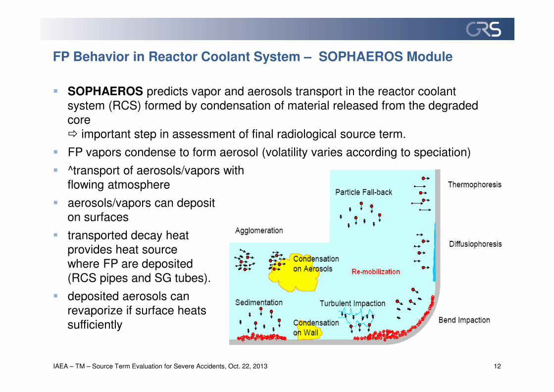
� SOPHAEROS predicts vapor and aerosols transport in the reactor coolant
system (RCS) formed by condensation of material released from the degraded
core
� important step in assessment of final radiological source term.
� FP vapors condense to form aerosol (volatility varies according to speciation)
� ^transport of aerosols/vapors with
flowing atmosphere
� aerosols/vapors can deposit
on surfaces
� transported decay heat
provides heat source
where FP are deposited
(RCS pipes and SG tubes).
� deposited aerosols can
revaporize if surface heats
sufficiently
FP Behavior in Reactor Coolant System – SOPHAEROS Module
IAEA – TM – Source Term Evaluation for Severe Accidents, Oct. 22, 2013 12

FP Behavior in RCS – SOPHAEROS Module
IAEA – TM – Source Term Evaluation for Severe Accidents, Oct. 22, 2013 13
� Aerosol models – phenomena taken into account:
• Agglomeration:
− Gravitational: Pruppacher & Klett,
− Brownian diffusion,
− Turbulence, shear and inertial: Saffman & Turner.
• Deposition:
− Gravitational: Stokes + Cunningham correction,
− Diffusion: Brownian (Gormley & Kennedy) or turbulent (Davies),
− Turbulent impaction: Liu & Argawal,
− Thermophoresis: Talbot et al.,
− Diffusiophoresis: Waldmann or Loyalka based on Stefan velocity,
− Bend impaction: centrifugal or Cheng & Wang/Pui et al.
• Remobilisation of deposits:
− Thermal re-vaporisation,
− Mechanical resuspension: drag-lift-adhesion model

IAEA – TM – Source Term Evaluation for Severe Accidents, Oct. 22, 2013 14
Ex-Vessel Fission Product Release

FP Behavior in Containment – CPA Module
IAEA – TM – Source Term Evaluation for Severe Accidents, Oct. 22, 2013 15
1- Gas
2- Aerosol
3- Gas phase surfaces
4- Water
5- Water phase surfaces
6- Safety systems (filter, etc.)
� Aerosol and FP behaviour:
• aerosol (insoluble, hygroscopic) transport and depletion models:
sedimentation, diffusiophoresis, thermophoresis
• condensation of aerosols,
• aerosol retention through water
pools (pool-scrubbing model
SPARC-B),
• aerosol removal by spray,
including wash-out of deposits
on containment walls,
• FP transport and calculation
of decay heat of gaseous and
particulate FP,
• FP/aerosols retention in concrete
walls cracks.
• filter models: granulate and fibre filter types,
retention due to: interception, impaction, diffusion

FP Behavior in Containment – IODE Module
IAEA – TM – Source Term Evaluation for Severe Accidents, Oct. 22, 2013 16
� Chemical reactions in sump and gas phase
in each containment zone,
• reactions in liquid phase:
− hydrolysis of molecular iodine,
radiolytic oxidation of I-, pH influence …
• reactions in gas phase:
− oxidation of molecular iodine by O3 air
radiolysis products, formation of organic
iodine (CH3I) from painted walls,
− adsorbtion/desorption of molecular iodine on
walls,
− CH3I destruction, O3 formation,
• mass transfers sump-gas phase.
R
ADSORPTION/
DESORPTION OF I2
Organics release
AerosolsIode-MétalCsI, AgI, CdI2…
I2R
CH3IOrganics release
CH3I(g)I2(g)
settling
air + H2O ���� O3
IxOyNz +
IxOy
I2
CH
I-, HOI, IO3-
3I
R
Adsorption/desorption of I2

Ex-Vessel Fission Product Release/behaviour – MCCI etc.
IAEA – TM – Source Term Evaluation for Severe Accidents, Oct. 22, 2013 17
� Release during corium-concrete interaction (MCCI)
• similar to ELSA (in-vessel) approach
• chemical equilibrium in a well-mixed molten pool assumed
• only semi- and low-volatiles are concerned
• release can be evaluated by thermodynamic calculations
• release for Zr-rich corium and siliceous concrete
� release from boiling sump
• re-suspension of aerosol trapped in sump water
• semi-empirical models deduced from REST (FZ-Karlsruhe) experiments
• lower release as compared to in-vessel release (but long term process)
� mechanical re-suspension of aerosols deposited on containment walls / floors
(e.g. in case of hydrogen deflagration)

IAEA – TM – Source Term Evaluation for Severe Accidents, Oct. 22, 2013 18
ASTEC validation

ASTEC Validation
IAEA – TM – Source Term Evaluation for Severe Accidents, Oct. 22, 2013 19
Illustration of main experiments used for ASTEC validation for FP release/behavior
ASTEC Validation – VERCORS Experiments
IAEA – TM – Source Term Evaluation for Severe Accidents, Oct. 22, 2013 20
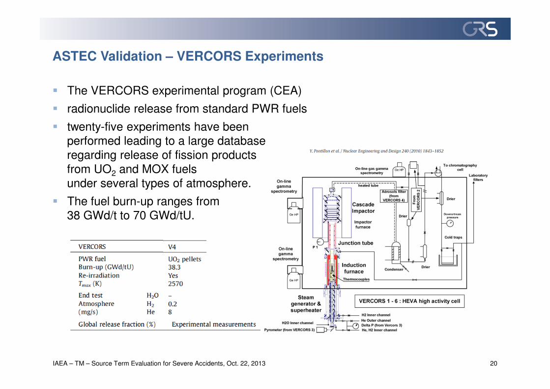
� The VERCORS experimental program (CEA)
� radionuclide release from standard PWR fuels
� twenty-five experiments have been
performed leading to a large database
regarding release of fission products
from UO2 and MOX fuels
under several types of atmosphere.
� The fuel burn-up ranges from
38 GWd/t to 70 GWd/tU.

ASTEC Validation – VERCORS Experiments
IAEA – TM – Source Term Evaluation for Severe Accidents, Oct. 22, 2013 21
� VERCORS 4 (Fuel burn-up 38.3 GWd/tU)
� key parameters: the temperature ramp, the burn-up of the fuel sample, gas
composition (steam and/or hydrogen), and flow rate
� oxidizing plateau with a mixed steam and hydrogen flow at a temperature of
around 1570 K preceded most of these tests, in order to completely oxidize the
cladding before the last heating ramp to the final high temperature plateau
Temperature volatile
FP release

ASTEC Validation – VERCORS Experiments
IAEA – TM – Source Term Evaluation for Severe Accidents, Oct. 22, 2013 22
Low-volatile
FP release
Semi-volatile
FP release
ASTEC Validation – Phebus Experiments
IAEA – TM – Source Term Evaluation for Severe Accidents, Oct. 22, 2013 23
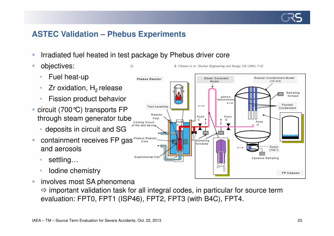
� Irradiated fuel heated in test package by Phebus driver core
� objectives:
• Fuel heat-up
• Zr oxidation, H2 release
• Fission product behavior
� circuit (700°C) transports FP
through steam generator tube
• deposits in circuit and SG
� containment receives FP gas
and aerosols
• settling…
• Iodine chemistry
� involves most SA phenomena
� important validation task for all integral codes, in particular for source term
evaluation: FPT0, FPT1 (ISP46), FPT2, FPT3 (with B4C), FPT4.

ASTEC Validation – Phebus Experiments
IAEA – TM – Source Term Evaluation for Severe Accidents, Oct. 22, 2013 24
In-vessel volatile FP release – ELSA results
FP release to containment –
SOPHAEROS results

ASTEC Validation – Phebus Experiments
IAEA – TM – Source Term Evaluation for Severe Accidents, Oct. 22, 2013 25
ELSA results
In-vessel semi-volatile FP release In-vessel low-volatile FP release
annulus air
extraction system
environment
filter20OBKUPPEL
18KUPPELA
11OPERA
10UPERA
21RRUNTEN
22RRMITTE
23 RROBEN
12UPERB
5DH
HKPB
4HKPA
19KUPPELB
13OPERB
FILTER24
ENVIRON
16UKUPA
17UKUPB
8DEOBOXA
9DEOBOXB
7DEMBOXB
14RRAUM
CAVITY
3PKLB
1SUMPF
1SUMPF
2PKLA
6DEMBOXA
ATMOS_JU
RUPTURE
DRAIN_BOT
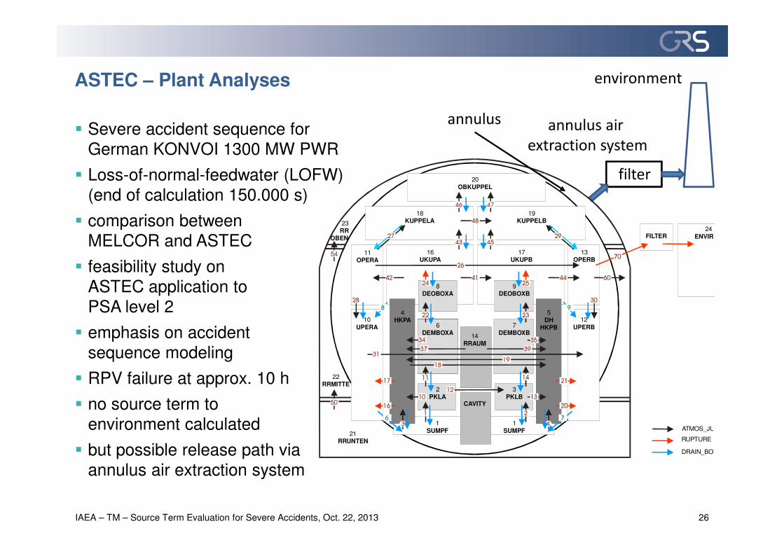
� Severe accident sequence for
German KONVOI 1300 MW PWR
� Loss-of-normal-feedwater (LOFW)
(end of calculation 150.000 s)
� comparison between
MELCOR and ASTEC
� feasibility study on
ASTEC application to
PSA level 2
� emphasis on accident
sequence modeling
� RPV failure at approx. 10 h
� no source term to
environment calculated
� but possible release path via
annulus air extraction system
ASTEC – Plant Analyses
IAEA – TM – Source Term Evaluation for Severe Accidents, Oct. 22, 2013 26
annulus

ASTEC – Plant Analyses
IAEA – TM – Source Term Evaluation for Severe Accidents, Oct. 22, 2013 27
� Source term for KONVOI PWR LOFW (at end of calculation 150.000 s)
� possible release from annulus via air extraction system (filtered) into environment
� orders-of-magnitute agreement despite different modeling approaches
MELCOR ASTEC MELCOR ASTEC MELCOR ASTEC MELCOR ASTEC MELCOR ASTEC
Xe 9,91E-01 9,99E-01 2,29E-05 1,03E-03 9,45E-04 3,32E-03 9,87E-01 9,96E-01 2,93E-03 3,99E-03
CsOH 9,85E-01 9,99E-01 3,34E-05 1,01E-03 1,18E-01 1,35E-01 8,67E-01 8,64E-01 1,14E-04 2,26E-05
Ba 4,20E-02 6,21E-03 9,43E-01 9,90E-01 4,29E-04 5,86E-03 4,15E-02 3,56E-04 3,37E-06 0,00E+00
Te 9,08E-01 9,75E-01 8,05E-02 2,52E-02 5,39E-02 2,78E-01 8,54E-01 6,97E-01 1,01E-04 1,70E-05
Ru 4,75E-02 1,47E-04 9,37E-01 9,58E-01 6,69E-03 1,02E-04 4,08E-02 4,52E-05 5,40E-06 0,00E+00
Mo als Element 1,22E-01 8,61E-01 2,27E-04 3,01E-02 1,35E-03 9,22E-02 1,73E-07 2,46E-06
Mo als Cs2MoO4 1,78E-03 5,06E-02 3,26E-06
Ce 3,47E-03 3,71E-05 9,81E-01 9,59E-01 3,86E-06 1,16E-05 3,46E-03 2,56E-05 1,26E-07 0,00E+00
La 3,62E-03 3,75E-05 9,81E-01 9,59E-01 3,19E-04 1,19E-05 3,30E-03 2,56E-05 4,19E-07 0,00E+00
U 5,10E-04 3,71E-05 9,76E-01 9,59E-01 6,96E-05 1,06E-05 4,40E-04 2,65E-05 5,74E-08 2,68E-08
Cd (Sb) 6,32E-01 9,82E-01 3,57E-01 1,76E-02 7,21E-02 1,31E-01 5,60E-01 8,52E-01 7,35E-05 0,00E+00
Sn 6,07E-01 3,84E-05 3,81E-01 9,59E-01 7,19E-02 2,79E-05 5,35E-01 1,05E-05 7,06E-05 0,00E+00
CsI (I) 9,66E-01 9,99E-01 2,34E-02 1,04E-03 4,06E-02 1,04E-03 9,25E-01 8,58E-01 1,03E-04 1,45E-05
Die Freisetzungsanteile wurden auf das Anfangsinventar der radioaktiven Spaltprodukte normiert
5,39E-02 9,46E-01
Gesamt aus Kern Verbleibend im Kern Im RKL Im Containment Außerhalb Containmentreleased from core remaining in core in primary circuit in annulusin containment

ASTEC – Plant Analyses
IAEA – TM – Source Term Evaluation for Severe Accidents, Oct. 22, 2013 28
� Additional analyses performed by IRSN on source term
assuming:
• various initiating events : LOCA, LFW, SBO
• location and size of the break : hot and cold leg
• availabilities of safety systems
• that the containment and the containment venting system (filtered containment
venting (FCV)) won’t fail
� Preliminary results focusing on iodine:
• uncertainties on iodine phenomenology knowledge have an important impact,
in the same order of magnitude as the variability due to the scenario
• gaseous iodine mass fraction and iodine oxide mass deposition rate are the
major contributors to these uncertainties
• sensitivity analysis module (SUNSET) helps to establish ranking of the studied
effects

Conclusions – Severe Accident and Source Term Analyses
IAEA – TM – Source Term Evaluation for Severe Accidents, Oct. 22, 2013 29
� Develop adequate input for codes
• requires high knowledge of code user on severe accident phenomena
• need for adequate and sufficient information on plant specifics and design
• use real plant data without conservative assumptions
• need for appropriate modelling of relevant plant specifics and all probable fission product release paths into the environment
• need for sufficient detail of nodalisation schemes for all components and buildings to allow a realistic simulation of NPP behaviour under severe accident conditions
� Validate developed input decks
• against real plant data for normal plant operating conditions
• by code to code comparisons with detailed (mechanistic) codes
� Perform uncertainty and sensitivity analyses

� Future ASTEC V2.1 version (end of 2014), which main features will be:
• generalization of the Material Data Base (MDB) use by all ASTEC modules
• new CESAR (T/H) / ICARE (core degradation) coupling
to account for e.g. late phase core re-flooding
• capability to simulate air ingress situations
incl. SFP behavior
• improved DCH modeling
• progress towards more complete BWR and PHWR (CANDU) applications
− description of canister components and account for multiple
in-core sub-channels (intra- and inter-canister flows),
− necessary adaptations to modeling core configuration with view to both
heat transfer and corium relocation models
− preliminary calculations of Fukushima accidents are already underway
Conclusions – Outlook
IAEA – TM – Source Term Evaluation for Severe Accidents, Oct. 22, 2013 30

IAEA – TM – Source Term Evaluation for Severe Accidents, Oct. 22, 2013 31
Thank you for your attention…
The author appreciates valuable contributions from the whole ASTEC team from IRSN and GRS