assessment procedure for durability of thin metallic ... · tr 038 assessment procedure for...
TRANSCRIPT

EUROPEAN ORGANISATION FOR TECHNICAL APPROVALS
E TAE TA
EUROPEAN ORGANISATION FOR TECHNICAL APPROVALS
TECHNICAL REPORT
Assessment procedure for durability of thin
metallic composite panels
TR 38Edition August 2012

FOREWORD 1 SCOPE 2 ACRONYMS AND SYMBOLS 3 PRINCIPLES 4 DECAY OF CHARACTERISTICS 4.1 Delamination resistance by peeling test 4.2 Flexural resistance by FPB test 4.3 Flexural stiffness by FPB test 4.4 Resistance of routed and returned edge to flexural - pulsating loads 4.5 Resistance of slot and its fixing device to pull out - pulsating loads 4.6 Corrosion protection 4.7 Retention of colour and gloss of coil coated aluminium sheets 5 COMMON AGEING EXPOSURES 5.1 Hygrothermal cycles 5.2 Immersion 6 h. in boiling water at 90º C 5.3 Immersion 500 h. in water at 20º C 5.4 Freeze-thaw cycles 5.5 Long term exposure to heat (2500 h. at hot dry air 80º C) ANNEX I EXAMPLE OF SAMPLING ANNEX II TERMINOLOGY ANNEX III SYNOPSIS ANNEX IV GENERAL TEST RESULTS STATISTICAL INTERPRETATION ANNEX V REFERENCE DOCUMENTS

TR 038 Assessment procedure for durability of thin metallic composite panels
Page 2 of 20
FOREWORD EOTA Technical Reports (hereafter TR) are developed as supporting reference documents to European Technical Approval Guidelines (hereafter ETAG) and can also be applicable to Common Understanding of Assessment Procedures (hereafter CUAP), EOTA Comprehension Documents or European Technical Approvals (hereafter ETA), as far as reference is made therein. TR goes into detail in some aspects and expresses the common understanding of existing knowledge and experience of the EOTA Bodies at a particular point in time. Where knowledge and experience is developing, especially through approval work, TR can be amended and supplemented. When this happens, the effect of the changes upon the ETAG will be laid down in the relevant comprehension documents, unless the ETAG is revised. This TR has been prepared by IETcc and endorsed by EOTA. 1 SCOPE This EOTA Technical Report n. 038 edition August 2012 is used as substituting Document of the chapters related to durability assessment of thin metallic composite panels (hereafter TMCP) contained in an ETAG. This TR specifies the provisions, tests methods and requirements for assessing the durability of these panels in order to determine the effect of adequate exposures on various characteristics by specific and/or comparative testing. Thin metallic composite panels covered by this TR are those able to be machined or joined (e.g. screwed, drilled, routed, bent, etcetera), with total thickness between 3 and 8 mm, composed by:
o Faced skins made of:
- Aluminium alloy sheets according to EN 485-2:2008 and EN 485-4:1993 (1)
, surface treated (coil coated according to EN 1396:2007
(2), anodized according
to EN ISO 7599:2010 (3)
) or not, with nominal thickness of external/internal sheet ≥ 0.5 mm [± 8%].
- Stainless steel sheets according to EN 10088-1:2005 and EN 10088-2:2005
(4)
with nominal symmetric thicknesses of sheet from 0.20 up to 0.40 mm [± 5%]. o Core made mainly of low density polyethylene and/or made of mineral compounds,
fulfilling its previously characterized fingerprint (e.g. by TGA, infrared analysis) at initial type testing.
o Adhesive layer for bonding faced skins and core through a continuous industrial
process.
The assessment of durability of other fully / partially bonded cladding kits / panels is not covered by this TR.

TR 038 Assessment procedure for durability of thin metallic composite panels
Page 3 of 20
2 ACRONYMS AND SYMBOLS Table 1
Acronym or symbol
Concept, characteristic or procedure Units Remarks
CK Cladding kit -- --
ETA European Technical Approval -- --
ETAG European Technical Approval Guideline -- --
FPB Four points bending test -- --
LDPE Low density polyethylene -- --
NPD No performance determined -- --
PVDF Polyvinylidene Fluoride -- --
RB Riveted boards -- --
SC Suspended cassettes -- --
TGA Thermogravimetric analysis -- --
TMCP Thin metallic composite panels -- --
TPB Three points bending test -- --
TR EOTA Technical Report -- --
UV Ultraviolet radiation (type A or B) -- --
d m Deflection in the middle of span mm --
d 80 ME Deflection at 80º C mean value mm FPB 1 h. at 80º C
d 20 ME Deflection at 20º C mean value mm FPB 1 h. at 20º C
∆ E AGED Colour difference aged value ∆E
∆ E INI Colour difference initial value ∆E EN 13523-3
F AGED u,5 Load characteristic aged value N
F INI u,5 Load characteristic initial value N
Annex IV of this TR
Gloss AGED Specular gloss aged value %
Gloss INI Specular gloss initial value % EN 13523-2
RH Relative Humidity % --
T AGED Torque peel average* aged value N.mm/mm
T INI Torque peel average* initial value N.mm /mm ASTM D 1781-98
* Remark: The term “average”, instead of “mean”, has been maintained as it is described at ASTM D 1781-98
3 PRINCIPLES 3.1 Working life category The evaluation of durability has been considered mainly as decay of performance characteristics after ageing exposures
(5). According to EOTA Guidance Document 002
(6) the
panel and/or kit based on these panels can be considered as “repairable or replaceable with some more efforts”. For this reason the provisions, test and assessment methods described or referred to in this TR, have been written based upon the assumed intended working life of at least 25 years provided that panel and/or kit are subjected to appropriate use and maintenance. These provisions, tests and assessment methods are based upon the current state of art and available experience. 3.2 General stipulations for sampling Sampling for tests shall be representative enough of panel and/or kit foreseen to be delivered to the market. For this purpose, the manufacturer shall carry out and adequate factory production control including registration of obtained data. For each test, the set of specimens shall be sampled from the same batch at least 24 h after its manufacture. For panels which are produced in more than one thickness, the tests shall be conducted as minimum on samples of maximum and minimum thickness. For initial state, specimens shall be conditioned before tests for 24 hours under laboratory conditions, considered in this TR as a temperature of 23 (± 2) °C and RH of 50 (± 5) % in accordance with ISO 554
(7). An example of sampling is specified in
Annex I.

TR 038 Assessment procedure for durability of thin metallic composite panels
Page 4 of 20
3.3 Durability reference framework The general assessment of fitness for use in relation to Essential Requirements has been drafted at the corresponding ETAG.
Table 2
Durability aspect
Characteristic (C) (expression)
Exposure (E) TR
paragraph Acceptance
Allowed NPD
Decay of delamination resistance
(Torque peel average value T)
(C): § 4.1 (E): § 5.1
• No cracks or breakage of metallic sheet and
• T AGED > 0,75 T INI and
• All individual aged values shall be within ± 15% of T AGED
NO
Thermal
Decay of flexural resistance * (Maximum load characteristic value F u,5)
Hygrothermal cycles test
(C): § 4.2 (E): § 5.1
• No cracks, breakage or dela-mination and
• F AGED u,5 > 0,75 F INI u,5 NO
Decay of delamination resistance
(Torque peel average value T)
(C): § 4.1 (E): § 5.2
• No cracks or breakage of metallic sheet and
• T AGED > 0,75 T INI and
• All individual aged values shall be within ± 15% of T AGED
NO
Decay of flexural resistance * (Maximum load characteristic value F u,5)
Immersion 6 h. in boiling water
at 90º C
(C): § 4.2 (E): § 5.2
• No cracks, breakage or dela-mination and
• F AGED u,5 > 0,75 F INI u,5
NO
Decay of delamination resistance
(Torque peel average value T)
(C): § 4.1 (E): § 5.3
• No cracks or breakage of metallic sheet and
• T AGED > 0,75 T INI and
• All individual aged values shall be within ± 15% of T AGED
NO
Water
Decay of flexural resistance * (Maximum load characteristic value F u,5)
Immersion in water 500 h. at
20º C
(C): § 4.2 (E): § 5.3
• No cracks, breakage or dela-mination and
• F AGED u,5 > 0,75 F INI u,5 NO
Decay of delamination resistance
(Torque peel average value T)
(C): § 4.1 (E): § 5.4
• No cracks or breakage of metallic sheet and
• T AGED > 0,75 T INI and • All individual aged values shall
be within ± 15% of T AGED
NO
Frost
Decay of flexural resistance * (Maximum load characteristic value F u,5)
Freeze-thaw cycles
(C): § 4.2 (E): § 5.4
• No cracks, breakage or dela-mination and
• F AGED u,5 > 0,75 F INI u,5 NO
Decay of delamination resistance
(Torque peel average value T)
(C): § 4.1 (E): § 5.5
• No cracks or breakage of metallic sheet and
• T AGED > 0,75 T INI and • All individual aged values shall
be within ± 15% of T AGED
NO
Decay of flexural resistance * (Maximum load characteristic value F u,5)
Long term exposure to heat (2.500 h. at hot dry air 80º C)
C): § 4.2 (E): § 5.5
• No cracks, breakage or dela-mination and
• F AGED u,5 > 0,75 F INI u,5
NO Heat
Decay of flexural stiffness (Maximum increment of deflection mean
value d ME)
Short term exposure
1 h. +80º C
(C): § 4.3 (E): § 4.3
• No cracks, breakage or dela-mination and
• d 80 ME ≤ 1,25 d 20 ME
NO
Decay of resistance of routed and returned edge
(Maximum load characteristic value F u,5)
TPB test Flexural
pulsating loads
(C): § 4.4 (E): § 4.4
• No cracks, breakage or dela-mination and
• F AGED u,5 > 0,75 F INI u,5
NO Fatigue
(only SC) Decay of resistance of slot and its fixing device
(Maximum load characteristic value F u,5)
Pull out pulsating loads
(C): § 4.5 (E): § 4.5
• No cracks, breakage or dela-mination and
• F AGED u,5 > 0,75 F INI u,5
NO
Infiltration (Length)
(coil coated aluminium sheets)
Salt spray (fog) (Accelerated test)
(C): § 4.6.1 (E): § 4.6.1
According to declared index of corrosion resistance from Table C.4 of EN 1396
NO
Corrosion Degree of blistering
(coil coated aluminium sheets) (Quantity and size of blisters )
Humidity. (Continuous
condensation) Accelerated test
(C): § 4.6.2 (E): § 4.6.2
• No blistering after 500 h. and • ≤ B2(S2) after 1.000 h (According to Table C.4 of EN 1396)
NO
Humidity. (Continuous
condensation) Accelerated test
UV-and water condensation
Others
Retention of colour (∆E) and gloss (%)
(only coil coated aluminium sheets)
Accelerated ageing by heat
(C): § 4.7 (E): § 4.7
• ∆ E AGED ≤ 5 and • Gloss AGED ≥ 0,8 Gloss INI
YES
* Remark: Required only for TMCP with core made of post-consumption LDPE, with or without mineral compounds
TR 038 Assessment procedure for durability of thin metallic composite panels
Page 5 of 20
4 DECAY OF CHARACTERISTICS
4.1 Delamination resistance by peeling test Peeling tests shall be carried out following procedure described below. Delamination resistance is a fundamental parameter for the assessment of deterioration of panels in comparative terms, and the results are not intended to be used for calculus.
4.1.1 Preparation and conditioning of specimens Couples of specimens shall be taken
from left, central and right side of panels cut in
perpendicular sense of lamination [a]
. For each panel thickness considered a set of 6 specimens per initial state and 6 per each ageing exposure considered shall be prepared. 3 specimens of each set shall be subjected to top metallic sheet - core peeling test and other 3 to bottom metallic sheet – core peeling tests. Specimens shall be length x width = 305 mm x 76 mm. An example of sampling is shown in Annex I. 4.1.2 Testing procedure 4.1.2.1 Delamination resistance by peeling test Peeling test shall be carried out according to ASTM D 1781-98
(8). The test shall be
carried out in laboratory conditions at initial state and after the required exposures. 4.1.2.2 Exposures The following and non consecutive exposures shall be carried out:
• Hygrothermal cycles.
• Immersion for 6 h. in boiling water at 90º C.
• Immersion for 500 h. in water at 20º C.
• Freeze-thaw cycles.
• Long term exposure to heat (2.500 h. at hot dry air 80º C). Following any of these ageing exposures as specified at § 5 of this TR, specimens shall be tested according to the required procedure. 4.1.3 Expression of results The report shall contain the following data:
• Description of specimens: Batch and date of manufacture, type of panel, thickness of panel, thickness of sheet, location on panel side (left, central or right) and metal sheet – core position (top or bottom).
• Initial individual and average values of torque peel strength, (TINI) expressed in N.m/m.
• Aged individual and average values (T AGED), expressed in N.m/m and whether acceptance criteria are fulfilled. In particular, no cracks or breakage on metallic sheet shall occur during peeling test due to unacceptable tensile strength.
• Description of any signs of degradation after visual inspection on each specimen after exposure and after testing.
[a] If required, at least other 6 specimens from left, central and right side of panels cut in the sense of lamination (perpendicular to panel width) shall be tested at initial conditions in order to verify there is no influence of the lamination manufacturing process.

TR 038 Assessment procedure for durability of thin metallic composite panels
Page 6 of 20
4.2 Flexural resistance by FPB test 4.2.1 Preparation and conditioning of specimens A set of 36 specimens samples (length x width: 1000 x 100 [± 0,5] mm) per panel thickness (6 per initial conditions and 6 per each exposure) shall be prepared. 4.2.2 Testing procedure 4.2.2.1 Flexural resistance by four points bending test Four points bending (FPB) tests shall be carried out. For this purpose a universal testing device class 0.5, a deflection measurement device type LVDT and four steel cylinders diameter 35 mm helped supported by thin strips in order to avoid damages on metallic sheets shall be used, according to the Figure 1. Specimens shall be placed with its front sheet facing downwards and its rear sheet facing upwards. The test shall be carried out in laboratory conditions.
Figure 1. Scheme of FPB test (dimensions in mm) Load F shall be applied at uniform speed of 5 mm/min, and deflection dm has to be measured on the middle of span. Test is stopped when maximum deflection or breakage is reached, and its F value is registered. 4.2.2.2 Exposures The following and non consecutive exposures shall be carried out:
• Hygrothermal cycles. • Immersion 6 h. in boiling water at 90º C.
• Immersion 500 h. in water 20º C.
• Freeze-thaw cycles.
• Long term exposure to heat (2.500 h. at hot dry air 80º C). Following any of these ageing exposures as specified at § 5 of this TR, specimens shall be tested according to the required procedure. . 4.2.3 Expression of results The report shall content the following data:
• Description of specimens: Batch and date of manufacture, type of panel, thickness of panel and thickness of sheets.
• The initial individual, mean and characteristic (F INI u,5) values of maximum load F (corresponding to maximum deflection or breakage) expressed in N.
• Aged individual, mean and characteristic (F INI u,5) values of maximum load F, (corresponding to maximum deflection or breakage) expressed in N and if acceptance criteria is fulfilled.

TR 038 Assessment procedure for durability of thin metallic composite panels
Page 7 of 20
• Description of any signs of degradation after visual inspection on each specimen after exposure and testing.

TR 038 Assessment procedure for durability of thin metallic composite panels
Page 8 of 20
4.3 Flexural stiffness by FPB test 4.3.1 Preparation and conditioning of specimens As minimum, a set of 12 specimens longitudinally oriented (length x width: 1000 x 100 [± 0,5] mm) per panel thickness shall be prepared (6 specimens per initial conditions and 6 specimens per final temperature). 4.3.2 Exposure/Testing procedure Four-points bending (FPB) tests shall be carried out. For this purpose two weight units (Ø 100 mm) able to reach maximum admissible load corresponding to permissible stress in cover sheets shall be used, as well as a deflection measurement device suitable to work at 80 (± 2) ºC and two steel cylinders diameter 35 mm accompanied by thin strips in order to avoid damage on metallic sheets. The visible panel surface shall be positioned facing downwards.
Figure 2. Scheme of creep resistance test (dimensions in mm)
According to Figure 2, specimens shall be placed in an adequate heat chamber. Weight units able to reach maximum permissible stress in metallic sheet declared by applicant shall be applied when test temperature is reached and deflection dm shall be measured at initial conditions (20 (± 2) °C) and at 80 (± 2) ºC, after 1 hour submitted to these respective expositions. 4.3.3 Expression of results The report shall content the following data:
• Description of specimens: Batch and date of manufacture, type of panel, thickness of panel and thickness of sheets.
• Individual and mean deflection values (expressed in mm) corresponding to initial conditions after 1 hour at 20 (± 2) °C (d 20 ME) and after 1 hour at 80 (± 2) ºC (d 80 ME) respectively and whether acceptance criteria as described in Table 2 are fulfilled. In particular, no cracks, delamination or breakage shall occur during test.
• Description of any signs of degradation after visual inspection on each specimen after exposure and after testing.

TR 038 Assessment procedure for durability of thin metallic composite panels
Page 9 of 20
4.4 Resistance of routed and returned edge to flexural - pulsating loads 4.4.1 Preparation and conditioning of specimens A set of 12 specimens per panel thickness, (6 per initial conditions and 6 per pulsating loads) with routed and returned edges on its short sides, and dimensions as defined in Figure 3 shall be prepared. Specimens edges shall be riveted to testing rigid profiles (which can be also component of the kit) fixed to testing frame. Dimensions “a” and “b” of the routed and returned edge shall correspond to manufacturer’s declared values.
2 rivets fixing edge to frame
a thic
kness
b
90º
Figure 3. Scheme of test (dimensions in mm)
4.4.2 Testing procedure 4.4.2.1 Flexural strength by three point bending test (TPB) Three-points bending tests shall be carried out under normal laboratory conditions. For this purpose a universal testing device class 0.5, a deflection measurement device type LVDT and an adequate clamping device shall be used, according to the Figure 3. Specimens shall be placed with their external side facing upwards.
Load shall be applied under normal laboratory conditions at a speed rate of 5 mm/min on the middle of span, until maximum initial load (FINI) corresponding to maximum deflection or breakage of routed and returned edge occurs. 4.4.2.2 Exposure Resistance to flexural - pulsating loads shall be tested by TPB under normal laboratory conditions. For this purpose, specimens shall be clamped at the middle of the span by adequate testing device able to transmit pulsating loads. Specimens shall be exposed to 10.000 load cycles at a frequency of 0,02 to 0,06 Hz. The maximum and the minimum pulsating loads (in N) shall be chosen accordingly. The following loads can be considered as appropriate:
• Maximum pulsating load Fmax = 50 % FINI u,5.
• Minimum pulsating load Fmin = 20 % FINI u,5.
Where FINI u,5 is the characteristic value determined according to Annex IV calculated from individual values obtained according to § 4.4.2.1. During each cycle the load shall vary like a sine curve between Fmax and Fmin. The edges shall be examined for cracks during the first loading up to max N and after 1, 10, 100, and 10.000 load cycles.

TR 038 Assessment procedure for durability of thin metallic composite panels
Page 10 of 20
After the completion of load cycles, the specimen shall be unloaded, the displacement shall be measured and a final TPB test shall be carried out according to § 4.4.2.1 until maximum load (FAGED) corresponding to maximum deflection or breakage of routed and returned edge occurs.
4.4.3 Expression of results The report shall content the following data:
• Description of specimens: Batch and date of manufacture, type of panel, thickness of panel and thickness of sheets, and dimensions “a” and “b” (see Figure 3).
• Individual, mean and characteristic values (FINI u,5), expressed in N, at initial state and after cycles (FAGED u,5) and whether acceptance criteria as described in Table 2 are fulfilled. In particular, no cracks, delamination or breakage shall occur during exposure to cycles.
• Load / displacement curves.
• Description of any signs of degradation after visual inspection on each sample after testing.
4.5 Resistance of slot and its fixing device to pull out - pulsating loads 4.5.1 Preparation and conditioning of specimens A set of 12 specimens per panel thickness, (6 for the initial conditions and 6 for the pulsating loads) and dimensions defined at Figure 4, plus their corresponding fixing devices shall be prepared. Distance “A” and dimension “B” shall correspond to manufacturer’s declared values.
200 mm
125
mm
Dimensions (mm)A (minimum thickness)B (maximum distance)O (diameter)
O
A B
Fixing device
Figure 4. Example of specimen
4.5.2 Testing procedure Initial resistance of slot (to pull out loads) reinforced or not by riveted profile on its lateral side, shall be tested in normal laboratory conditions, applying a speed rate of 5 mm/min on the specimen´s fixing device until maximum initial load (FINI) expressed in N, corresponding to maximum displacement or breakage is reached. In case of doubt on dead load or anti-lift up resistances, tests in the vertical direction of the cassette may be performed.

TR 038 Assessment procedure for durability of thin metallic composite panels
Page 11 of 20
4.5.3 Exposure Pull out pulsating loads resistance shall be tested under normal laboratory conditions. Specimens shall be exposed to 10.000 load cycles at a frequency of 2 to 6 Hz. The maximum and the minimum pulsating loads (in N) shall be chosen accordingly. The following loads can be considered as appropriate:
• Maximum pulsating load Fmax = 50 % FINI u,5
• Minimum pulsating load Fmin = 20 % FINI u,5. Where FINI u,5 is the characteristic value determined according to Annex IV calculated from individual values obtained according to § 4.5.2. During each cycle the load shall vary like a sine curve between Fmax and Fmin. The displacement shall be measured during the first loading up to Fmax, and after 1, 10, 100, and 10.000 load cycles. After completion of load cycles, the specimen shall be unloaded, the displacement measured and a final pull out test shall be carried out according to § 4.5.2 until load (FAGED) corresponding to maximum deflection or breakage of slot occurs. 4.5.4 Expression of results The report shall content the following data:
• Description of specimens: Batch and date of manufacture, type of panel, thickness of panel and thickness of sheets.
• Description of any signs of degradation after visual inspection on each specimen after exposure and/or testing.
• Individual, mean and characteristic values at initial state FINI u,5 and after cycles FAGED u,5 (expressed in N) and whether acceptance criteria as described in Table 2 are fulfilled. In particular, no cracks, delamination or breakage shall occur during exposure to cycles.
• Load/displacement curves. 4.6 Corrosion protection 4.6.1 Resistance to salt spray (fog) according EN 13523-8
(9)
4.6.1.1 Preparation and conditioning of specimens Specimens shall be sampled from the same panel and carefully cleaned and prepared according to applicant ´s instructions. For sampling at least 3 flat specimens (option 1 according to § 7.2 of EN 13523-8
(9)) per coating type (e.g. PVDF and thickness range) and exposure shall
be prepared for test. 4.6.1.2 Testing procedure
• 500 and 1.000 h. exposed to neutral salt fog as described at standard EN 13523-8 (9)
.
4.6.1.3 Expression of results
• Number and description of specimens: For panels, batch, date of manufacture, type and thickness. For sheets, its thickness, alloy, temper, coating type and coating thickness.
• If acceptance criteria for corrosion infiltration as described at Table C.4 of EN 1396 (2)
are fulfilled for both exposures (500 and 1.000 h.) according to the declared index of corrosion resistance.
TR 038 Assessment procedure for durability of thin metallic composite panels
Page 12 of 20
4.6.2 Degree of blistering of coil coated aluminium 4.6.2.1 Preparation and conditioning of specimens Specimens shall be sampled from the same coil and carefully cleaned and prepared according to applicant ´s instructions. At least 3 flat specimens (length 150 mm x width 75 mm, where length refers to lamination procedure) per coating type (e.g. PVDF - two layers) shall be prepared. 4.6.2.2 Testing procedure The resistance to humidity of sheet shall be determined after 500 and 1.000 h exposed to continuous condensation according to EN ISO 6270-1
(10).
4.6.2.3 Expression of results
• Number and description of specimens: For panels, batch, date of manufacture, types and thicknesses. For sheets, its thickness, alloy, temper, coating product and coating thickness).
• Whether both acceptance criteria as described in Table 2 are fulfilled. 4.7 Retention of colour and gloss of coil coated aluminium sheets The assessment of these characteristics shall be carried out, except if NPD option is considered, according to the following tests procedures:
• Colour: EN 13523-3:2001 (11)
only for solid colours (not for metalized or iridescent coatings).
• Gloss: EN 13523-2:2001 (12)
measured at an angle of 60º for solid colours, and at angles of 25º, 45º and 75º for metalized or iridescent coatings.
At initial conditions and after all of these independent and non continuous exposures, according to the corresponding standards:
• Humidity (continuous condensation according to EN ISO 6270 – 1) (10)
.
• UV and water condensation (according to EN 13523 - 10) (13)
.
• Accelerated ageing by heat (according to EN 13523 – 13) (14)
. 4.7.1 Preparation and conditioning of specimens The quantity and size of specimens shall be sampled from same coil as described below. In any case, their lengths refer to lamination direction.
• Humidity (continuous condensation): See § 4.6.2.1 of this TR.
• UV and water condensation: Three flat specimens (length x width: 150 x 75 mm) shall be sampled from the same coil per coating type (e.g. PVDF - two layers).
• Accelerated ageing by heat: Three flat specimens (length x width: 150 x 75 mm) shall be sampled from the same coil per coating type (e.g. PVDF - two layers).
Conditioning before and after exposure, if required, shall be carried according to the exposure standard.

TR 038 Assessment procedure for durability of thin metallic composite panels
Page 13 of 20
4.7.2 Exposure and testing procedure
• Humidity (continuous condensation): See § 4.6.2.2 of this TR. • UV and water condensation: According to EN 13512-10
(13) only UV-A or UV-B shall
be used, taking into account the following inputs from Annex C of EOTA TR 010 (15)
:
o Climate: Moderate or severe according to Table C.1 and mean annual radiant exposure by global radiation isolines map of Europe.
o 5 years equivalent radiation dose for an assumed working life of 25 years. o UV Irradiance = 55 W/m
2 .
• Accelerated ageing by heat: 72 h. exposed to 90º C. 4.7.3 Expression of results
• Type of lamps, length of exposition, as well as number and description of specimens. For panels, batch, date of manufacture, types and thicknesses. For sheets, its thickness, alloy, temper, coating product and coating thickness).
• Initial values (∆E INI and Gloss INI) plus aged values (∆E AGED and Gloss AGED) and if both acceptance criteria for retention of colour and gloss as described in Table 2 are fulfilled.
5 COMMON AGEING EXPOSURES
Specimens shall be conditioned in accordance with ISO 554 (7)
at 23 (±2) °C and 50 (±5) % RH before the ageing exposure. After exposure, specimens shall be conditioned, if required, and tested immediately as described in the particular procedure. 5.1 Hygrothermal cycles Considering as initial conditions 23 (±2) °C and 50 (±5) % RH, and increase in temperature and relative humidity shall be applied at a heating rate of 1,5 ºC/min in order to start the hygrothermal cycle defined as follows:
• Exposure to temperature and humidity 90° C and 90% RH along 1 h.
• Decrease of temperature to -40° C along 2 ½ h.
• Exposure to temperature -40° C along 1 h.
• Increase of temperature and humidity up to +90º C and 90 % RH along 1 ½ h.
Total: 6 h. / cycle Eight cycles shall be carried out uninterruptedly. For panels which are produced in more than one thickness, the tests shall be conducted with samples from panels of both maximum and minimum thickness. The worst result shall apply to panels of all intermediate thicknesses. Then, it shall be calculated if the decay of mechanical resistance fulfils the respective acceptance criteria (specified at Table 2). 5.1.1 Apparatus
• Climatic chamber with internal dimensions able to contain different sizes of specimens and carry out steps and ranges of temperatures described above.
• Shelves: To support the test specimens and enabling a uniform heating or cooling and moisture exposition with dimensions to fix the test specimens.

TR 038 Assessment procedure for durability of thin metallic composite panels
Page 14 of 20
5.1.2 Procedure
• Introduce specimens and start cycle tests according to required conditions.
• After the end of the exposure period, specimens shall be removed from the chamber and cooled to ambient temperature (23 ± 2° C) at a rate of 1,5 ºC/min before further testing.
5.2 Immersion 6 h. in boiling water at 90º C
In order to determine effects on core and adhesive layer of water vapour diffusion, specimens shall be fully immersed in boiling water
[b] during 6 hours at 90º C.
5.2.1 Apparatus
• Containers of adequate volume able to storage different specimens.
• Connector: A socketed flat flanged lid used for connecting between flask and condenser.
• Condenser: To condense water vapour driven off by boiling to ensure a constant volume of water.
• Heater: An electric heating blanket providing uniform heating to the flask.
• Timer: A suitable device capable to measure duration.
• Thermometer: A suitable (accuracy ± 1º C) device capable to measure water’s temperature.
5.2.2 Procedure
1. Fill container to 2/3 of its volume using tap water. 2. Heat water to boiling using heating blanket. 3. Add prepared specimens to water, start timer, connect condenser and start
condenser. 4. After six hours in boiling water, specimens shall be taken out and cooled to ambient
temperature (23 ± 2 °C) before further testing. 5.3 Immersion 500 h. in water at 20º C In order to determine effects on core and adhesive layer of liquid water, specimens shall be fully immersed along 500 h. at 20º C uninterruptedly. 5.3.1 Apparatus
• Containers of adequate volume able to storage different specimens, capable to avoid water evaporation.
• Thermometer: A suitable (accuracy ± 1º C) device capable of measuring temperature of water.
5.3.2 Procedure
1. Immerse specimens in tap water. 2. After the exposure period, remove water from sample before further testing.
5.4 Freeze - thaw cycles
50 freeze-thaw cycles shall be carried out.
[b] Although strictly speaking bowling point of water is at 100º C under normal atmospheric pressure, it is maintained this term due to its extended use for testing conditions of 90º C

TR 038 Assessment procedure for durability of thin metallic composite panels
Page 15 of 20
5.4.1 Apparatus
• Freeze-thaw chamber with internal dimensions able to contain different sizes of specimens and to carry out steps and ranges of temperatures described at 5.4.2.
• Shelves: To support the test sample and enabling a uniform exposition with dimensions to fix the test specimens.
5.4.2 Procedure Each cycle shall be composed of:
• Full immersion of specimens in tap water bath for 8 h. at initial temperature of 20 (± 2) °C.
• Decrease to -20 (± 2) °C for 2 h. (in conditioned air).
• Exposure to - 20 (± 2) °C (in conditioned air) for 14 h.
In case of interruption, specimens shall always be positioned in water between the cycles. Specified temperatures shall be measured at specimen surface. For panels which are produced in more than one thickness, the tests shall be conducted with samples from panels of maximum and minimum thickness. The worst result shall apply to panels of all intermediate thicknesses. Finally it shall be calculated if the decay of mechanical resistance fulfils the respective acceptance criteria specified at Table 2. 5.5 Long term exposure to heat (2.500 h. at hot dry air 80 ºC) Specimens shall be exposed 2.500 h. to dry air at 80 (± 2º C) uninterruptedly. 5.5.1 Apparatus
• Oven: With forced air circulation and with temperature regulation to a range of 50 to 100° C with an accuracy of ± 2° C. The internal dimensions are such to contain the different sizes of specimens.
• Shelf: To support the test sample and enabling a uniform heating with dimensions to fix the test specimen.
5.5.2 Procedure
1. Bring the oven to the required temperature. 2. Place the test specimen on its supporting frame in the oven. 3. Maintain the required temperature during the specified period of time. 4. After the exposure period remove the sample from the oven, bring it back to
ambient temperature (23 ± 2° C) and maintain it at that temperature for 24 hours before further testing.

TR 038 Assessment procedure for durability of thin metallic composite panels
Page 16 of 20
ANNEX I EXAMPLE OF SAMPLING
La
min
atio
n s
en
se
of p
an
el
Slot resistance 12 specimens 200 x 125 mm
Delamination resistance: 30 specimens 305 x 76 mm
Flexural resistance/stiffness: 48 specimens 1000 x 10 mm
Resistance of routed and returned edge: 12 specimens 1080 x 100 mm
Figure 5: Scheme of sampling
TR 038 Assessment procedure for durability of thin metallic composite panels
Page 17 of 20
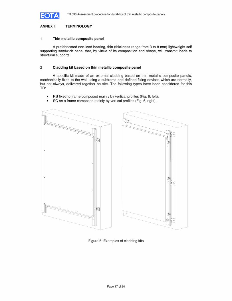
ANNEX II TERMINOLOGY 1 Thin metallic composite panel A prefabricated non-load bearing, thin (thickness range from 3 to 8 mm) lightweight self supporting sandwich panel that, by virtue of its composition and shape, will transmit loads to structural supports. 2 Cladding kit based on thin metallic composite panel A specific kit made of an external cladding based on thin metallic composite panels, mechanically fixed to the wall using a subframe and defined fixing devices which are normally, but not always, delivered together on site. The following types have been considered for this TR:
• RB fixed to frame composed mainly by vertical profiles (Fig. 6, left).
• SC on a frame composed mainly by vertical profiles (Fig. 6, right).
Figure 6: Examples of cladding kits

TR 038 Assessment procedure for durability of thin metallic composite panels
Page 18 of 20
ANNEX III SYNOPSIS
Panel is acceptable if all acceptance criteria (Table 2) are fulfilled are fulfilled in relation to:
Thermal: Decay of delamination and of flexural resistances
Water: Decay of delamination and of flexural resistances
Frost: Decay of delamination and of flexural resistances
Heat: Decay of delamination and of flexural resistances
Fatigue: Decay of resistance of routed and returned edge / slot
Corrosion. Decay of protection
POST
Panel is acceptable if all acceptan-ce criteria (Table 2) are fulfilled in relation to::
Thermal: Decay of delamination and of flexural resistances
Water: Decay of delamination and of flexural resistances
Frost: Decay of delamination and of flexural resistances
Heat: Decay of delamination and of flexural resistances
Fatigue: Decay of resistance of routed and returned edge / slot
Corrosion. Decay of protection
POST
RB
Is TCMP core made of
PRE or POST consumption
LDPE?
Panel is acceptable if all acceptance criteria (Table 2) are fulfilled in relation to:
Thermal: Decay of delamination resistance
Water: Decay of delamination resistance
Frost: Decay of delamination resistance
Heat: Decay of delamination resistance
Fatigue: Decay of resistance of routed and returned edge / slot
Corrosion. Decay of protection
PRE
Panel is acceptable if all acceptan-ce criteria (Table 2) are fulfilled in relation to:
Thermal: Decay of delamination resistance
Water: Decay of delamination resistance
Frost: Decay of delamination resistance
Heat: Decay of delamination resistance
Fatigue: Decay of resistance of routed and returned edge / slot
Corrosion. Decay of protection
PRE
Is TCMP core made of
PRE or POST consumption
LDPE?
SC
Yes
Is CK based on
SC or RB?
Decay of flexural stiffness by FPB test 1 h. 80º C
Is d80ME ≤1,25 d20ME?
Panel not acceptable
No

TR 038 Assessment procedure for durability of thin metallic composite panels
Page 19 of 20
ANNEX IV: GENERAL TEST RESULTS STATISTICAL INTERPRETATION
Fu,5 = Fmean - kn . S
∆Fmean = Fmean,c / Fmean,n
Where: Fu,5 = the characteristic breaking force giving 75 % confidence that 95 % of the test results will be higher than this value. F mean = the mean breaking force, either under tension or shear. F mean,n = the mean breaking force, either under tension or shear in the initial state. F mean,c = the mean breaking force, either under tension or shear after conditioning or ageing. kn = the eccentricity of 5 % with 75 % confidence (see Table 3). S = the standard deviation of series under consideration. Remark: The variable kn as a function of the number of test pieces (see EN 1990 Eurocode: Basis of structural design, Table D1, Vx, unknown).
Table 3 Number of
pieces 3 4 5 6 7 8 10 20 30 ∞
Variable kn 3,37 2,63 2,33 2,18 2,10 2,00 1,92 1,76 1,73 1,64
TR 038 Assessment procedure for durability of thin metallic composite panels
Page 20 of 20
ANNEX V REFERENCE DOCUMENTS
Reference documents referred to at this TR are listed below. The edition of a reference document given in this list is that which has been adopted by EOTA for its specific use. When a new edition becomes available, this supersedes the edition mentioned in the list only when EOTA has verified or reestablished (possibly with appropriate linkage) its compatibility with this EOTA TR.
1 EN 485-2:2008. Aluminium and aluminium alloys - Sheet, strip and plate - Part 2: Mechanical properties.
EN 485-4:1993. Aluminium and aluminium alloys – Sheet, strip and plate – Part 4: Tolerances on shape and dimensions for cold-rolled products.
2 EN 1396:2007. Aluminium and aluminium alloys. Coil coated sheet and strip for general
applications. Specifications.
3 EN ISO 7599:2010. Anodizing of aluminium and its alloys -- General specifications for anodic oxidation coatings on aluminium.
4 EN 10088-1:2005. Stainless steels - Part 1: List of stainless steels. EN 10088-2:2005. Stainless steels – Part 2: Technical delivery conditions for sheet/plate
and strips for general purposes. 5 GUIDANCE PAPER F: DURABILITY AND THE CONSTRUCTION PRODUCTS
DIRECTIVE. December 2004.
6 EOTA GUIDANCE DOCUMENT 002. Assumption of working life of construction products in
Guidelines for European Technical Approval, European Technical Approvals and Harmonized Standards. Edition December 1999.
7 ISO 554:1976. Standard atmospheres for conditioning and/or testing – Specifications. 8 ASTM D 1781-98 (2004): Standard Test Method for Climbing Drum Peel for Adhesives.
9 EN 13523-8:2008. Coil coated metals - Test methods - Part 8. Resistance to salt spray (fog). 10 EN ISO 6270-1: 2001. Paints and varnishes. Determination of resistance to humidity. Part 1. Continuous condensation.
11 EN ISO 13523-3:2001. Coil coated metals - Test methods - Part 3: Colour differences. 12 EN ISO 13523-2:2001. Coil coated metals - Test methods - Part 2: Specular gloss.
13 EN 13523-10: 2010. Coil coated metals - Test methods - Part 10. Resistance to fluorescent UV light and water condensation.
14 EN 13523-13:2001. Coil coated metals - Test methods - Part 13: Resistance to accelerated ageing by the use of heat.
15 EOTA TR 010. Exposure procedure for artificial weathering. Ed. May 2004.