assessment of a heat exchanger inlet nozzle flow using … · · 2010-11-03assessment of a heat...
TRANSCRIPT
ASSESSMENT OF A HEAT
EXCHANGER INLET NOZZLE FLOW
USING ANSYS-CFX®
Delvonei Alves de Andrade, Gabriel Angelo,
Gerson Fainer and Edvaldo Angelo

PRESENTATION TOPICS
• Company Overview;
• Problem Description;
• Methodology;
• Goals;
• Results;
• Conclusion and next steps.

COMPANY OVERVIEW
• IPEN – Nuclear and Energy Research Institute – National
Nuclear Energy Commission CNEN - autarchy, associated to
the University of São Paulo – USP for educational purposes
• Federal agency of the Ministry of Science and Technology.
• Founded in 1956 - main purpose - research and development
in the fields of nuclear energy and its applications.
• Located at the campus of USP - São Paulo
• Over 1.000 employees - 40% qualification at master or doctor
level.
• IPEN is recognized as a national leader institution in research
and development in the areas of radiopharmaceuticals,
industrial applications of radiation, basic nuclear research,
nuclear reactor operation and nuclear applications, materials
science and technology, laser technology and applications.
COMPANY OVERVIEW
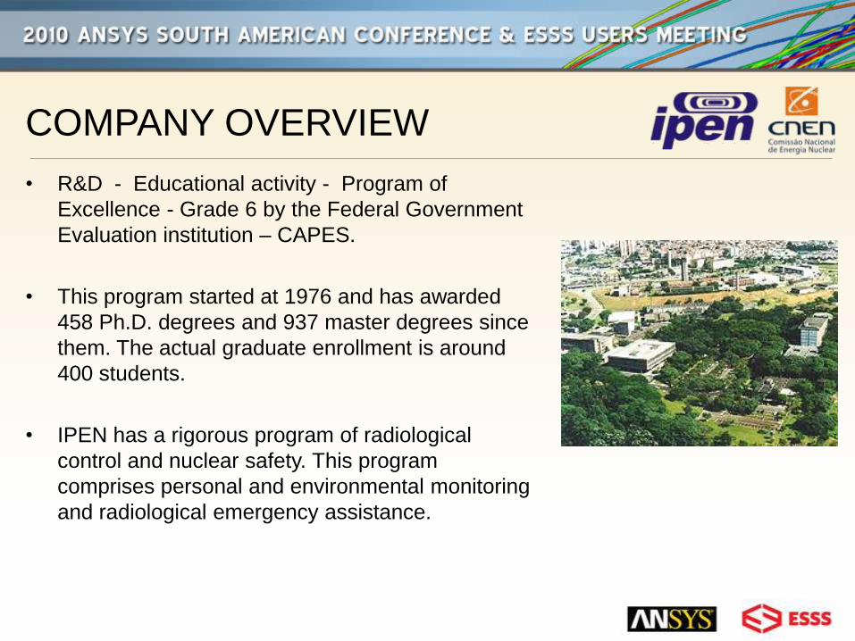
• R&D - Educational activity - Program of
Excellence - Grade 6 by the Federal Government
Evaluation institution – CAPES.
• This program started at 1976 and has awarded
458 Ph.D. degrees and 937 master degrees since
them. The actual graduate enrollment is around
400 students.
• IPEN has a rigorous program of radiological
control and nuclear safety. This program
comprises personal and environmental monitoring
and radiological emergency assistance.
PROBLEM DESCRIPTION
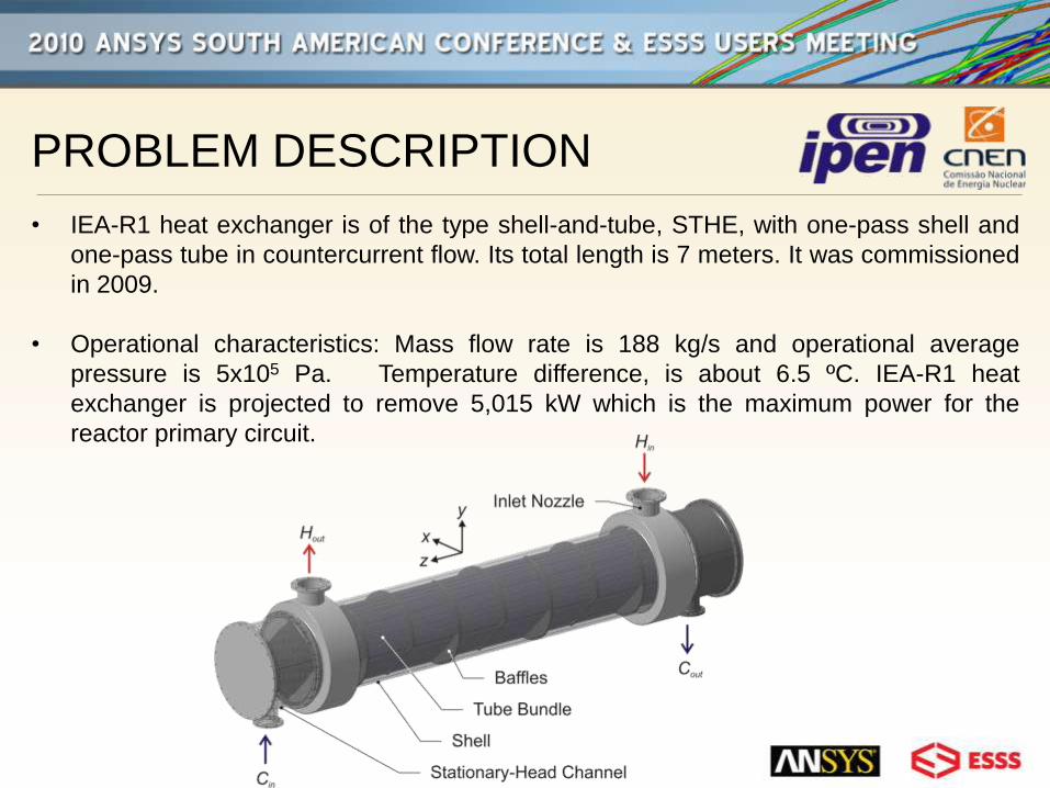
• IEA-R1 heat exchanger is of the type shell-and-tube, STHE, with one-pass shell and
one-pass tube in countercurrent flow. Its total length is 7 meters. It was commissioned
in 2009.
• Operational characteristics: Mass flow rate is 188 kg/s and operational average
pressure is 5x10⁵ Pa. Temperature difference, is about 6.5 ºC. IEA-R1 heat
exchanger is projected to remove 5,015 kW which is the maximum power for the
reactor primary circuit.

PROBLEM DESCRIPTION
• Inlet and outlet nozzles for the hot and cold fluid and stationary-head channel can
be observed. For the IEA-R1 STHE hot fluid is injected in the inlet nozzle into the
shell passing through the baffles and tube bundle towards the outlet nozzle. Cold
fluid removes the hot fluid heat and flows into the tube bundle in countercurrent
flow.
PROBLEM DESCRIPTION
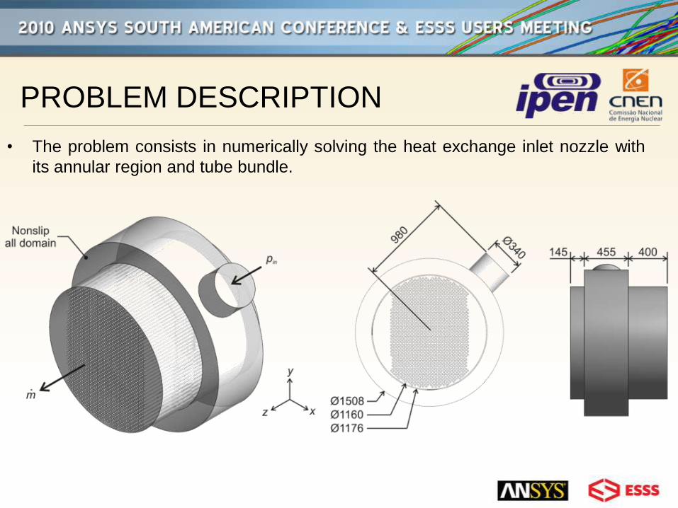
• The problem consists in numerically solving the heat exchange inlet nozzle with
its annular region and tube bundle.
METHODOLOGY
• Design-Modeler and CFX-Mesh were used for the construction of the geometry and
mesh generation, respectively, in the Workbench environment. A tridimensional model
was developed using the finite volume method applied to a tetrahedral non structured
mesh. Inflation layers were considered for the annular region.
• The equations considered are the mass conservation and momentum equation. k - e
model is considered for turbulence.
• Operation fluid is water in stationary regime. Due to the small temperature variation in
the inlet section, for this analysis flow is considered isothermal at 45 ºC.
• A volumetric element generation shows a degree of complexity. It is related to the fact
that some elements present aspect ratio of 100:1. It is illustrated when one compares
the shell diameter to the small tube diameter in the tube bundle. So that, the
computational domain comes to a size as to test the computer system limits.

METHODOLOGY
• Mesh dependency was studied and verified using Stern, F. at al. and Wilson, R. V. at al.
approach. The methodology considers, for the same boundary condition, an increase of the
mesh density using predefined ratios. This procedure must be performed in such a way that
property variation or small variations are not present. When this condition is satisfied the
solution is independent of the mesh. A mesh of approximately 28 million elements was
generated.
• In order to avoid turbulence behaviors as swirl, an increment of the outlet dimension of the
heat exchanger model was included.
• At first it is assumed an average velocity of 2.07 m/s for the inlet nozzle, which is based on
the mass flux. Pressure at the outlet of the heat exchanger is equal to the operation
pressure.
• Convergence criterion is controlled by setting the maximum residues to 0.0001 for all
variables.

METHODOLOGY
• Results of this preliminary analysis were used to initiate the final resolution. In this case the
operation pressure was set as the pressure at the inlet nozzle and mass flux was set as the
boundary condition at the outlet. It guarantees variations of velocity at the inlet nozzle and
variations of pressure at the heat exchanger outlet.
• Non slip condition is applied to all other surfaces.

GOALS
• CFX training task;
• Comparison between the simplified and this model;
• Better understanding of the heat exchanger inlet nozzle flow
dynamics.

RESULTS
• Pressure contour for the simplified and this model
RESULTS
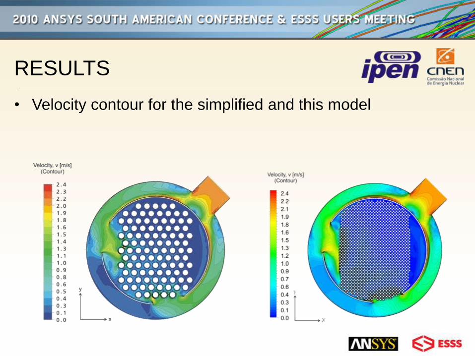
• Velocity contour for the simplified and this model

RESULTS
• Streamlines for the simplified and this model
RESULTS
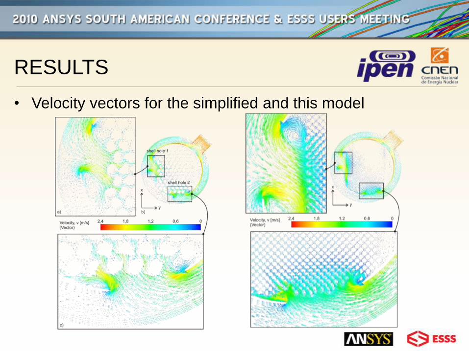
• Velocity vectors for the simplified and this model

Conclusions
• CFX showed to be a very useful CFD tool;
• New limits to our department computer systems were
established;
• A CFX model for the IEA-R1 reactor heat exchanger inlet
nozzle was created;
• The mathematical model results for the pressure field,
velocity field, streamlines and vectors showed consistency.
Next steps
• Investigation of other turbulence models;
• New model with an equivalent geometry in order to solve the
problem for the whole heat exchanger.