assessing the use of composite materials in repairing …
TRANSCRIPT

ASSESSING THE USE OF COMPOSITE MATERIALS IN REPAIRING AND
REINFORCING OFFSHORE RISER PIPES
Presented to the Regional Operations Technology Assessment Committee (ROTAC) Meeting Minerals Management Service (Pacific OCS Region) OTRC Presentation Chris Alexander Staff ConsultantSenior Associate Stress Engineering Services Inc chrisalexanderstresscom middot (281) 897-6504 (direct)
Stress Engineering Servicewwwstresscom
s Inc Presentation to the MMS ROTAC Meeting Camarillo California middot September 19 2006
Stress Engineering Services Inc wwwstresscom
Slide 2
Presentation Outline bull Review of current composite repair state of
the art bull Joint Industry Project (JIP) Program
ndash Task overview and schedule ndash Manufacturer participation ndash Analysis phase ndash Testing phase ndash Guideline development
bull Closing comments
Presentation to the MMS ROTAC Meeting Camarillo California middot September 19 2006
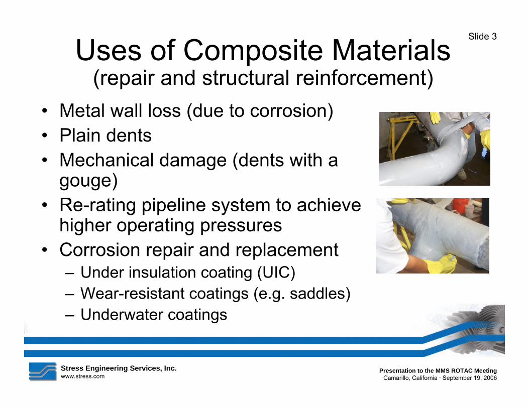
ndash Underwater coatings
Stress Engineering Services Inc Presentation to the MMS ROTAC Meeting wwwstresscom Camarillo California middot September 19 2006
Slide 3
Uses of Composite Materials(repair and structural reinforcement)
bull Metal wall loss (due to corrosion) bull Plain dents bull Mechanical damage (dents with a
gouge) bull Re-rating pipeline system to achieve
higher operating pressures bull Corrosion repair and replacement
ndash Under insulation coating (UIC) ndash Wear-resistant coatings (eg saddles)
Stress Engineering Services Iwwwstresscom
Slide 4
Types of Composite Repairs (used to repair pipeline systems)
bull Wet lay-up systems (eg Armor Plate Pipe WrapDiamond Wrap Aquawrap Comptek) ndash Monolithic ndash Can be applied to non-straight geometries ndash Versatility in range of epoxy products (eg underwater
high temperature etc) bull Layered systems (eg Clock Spring and
PermaWrap) ndash First widely-used composite repair system ndash Layered repair system ndash Limited to repair of straight pipes
nc Presentation to the MMS ROTAC Meeting Camarillo California middot September 19 2006
Stress Engineering Services Inc wwwstresscom
serviceability of the pipe
Slide 5
Government Regulations (from the US Department of Transportation) On January 13 2000 Pipeline Safety Gas and Hazardous Liquid Pipeline Repair was issued by the RSPA of the Department of Transportation went into effect
According to this document the requirement for repairing corroded and dents in pipelines is as follows
helliprepaired by a method that reliable engineering tests and analyses show can permanently restore the
Page from the RSPA-98-4733 document
Presentation to the MMS ROTAC Meeting Camarillo California middot September 19 2006
Slide 6
Guidelines for Evaluation of Composite Repair Methods
The basic fundamental issues for evaluating composite repair methods are as follows bull Strength of the composite material bull Environmental effects (eg cathodic
disbondment temperature acids and alkalines) bull Effects of pressure (both static and cyclic) bull Mechanics of load transfer from pipe to wrap bull Long-term performance issues bull Consistency in application and quality control in
manufacturing
Stress Engineering Servicewwwstresscom
s Inc Presentation to the MMS ROTAC Meeting Camarillo California middot September 19 2006
Stress Engineering Services Inc wwwstresscom
Slide 7
Mechanics of Composite Repair Methods
Equation defining burst pressure
P = Internal pressure σ = Material failure stress t = Thickness of material r = Radius of pipe
Note The above calculation is based on thin-wall shell theory and is not applicable for thick-walled pipes with diameter to wall thickness ratios less than 20
Presentation to the MMS ROTAC Meeting Camarillo California middot September 19 2006
Repaired section Non-repaired section (in 60 corroded area) (in base pipe)
0 1000 2000 3000 4000 5000 6000 7000 Hoop Strain (microstrain)
( 10 0 0 m ic ro s t ra in = 0 1 pe rc e nt s t ra in)
Pipe (top) Under composite (center) Under composite (1 f rom center) Under composite (2 f rom center) Composite (outside on top)
Inte
rnal
Pre
ssur
e (p
si)
3500
3000
2500
2000
1500
1000
500
0
Slide 8
Pipe-to-Composite Load Transfer(Hoop Strain During Pressurization)
Hoop Strain as a Function of Internal Pressure Comptek epoxy resin composite repair system (Sample 2)
1275-in x 0219-in Grade X52 pipe w ith 60 percent corrosion Burst pressure of 2931 psi (in unrepaired section of test sample)
Stress Engineering Serviceswwwstresscom
Inc Presentation to the MMS ROTAC Meeting Camarillo California middot September 19 2006
Stress Engineering Services Inc wwwstresscom
Slide 9Observations on Current Composite Repair Methods
bull For more than 10 years the pipeline industry has been making repairs usingcomposite materials
bull A significant body of research exists addressing a variety of repair types
bull The missing link in most of the composite repair systems is long-term test data(especially in terms of the adhesivesystems)
Presentation to the MMS ROTAC Meeting Camarillo California middot September 19 2006
Stress Engineering Services Inc Presentation to the MMS ROTAC Meeting wwwstresscom Camarillo California middot September 19 2006
Slide 10
JIP Program bull Elements of the program
ndash Task overview and schedule
ndash Manufacturer participation ndash Analysis phase ndash Testing phase ndash Guideline development
Slide 11
Task Overview and Schedule Tasks Year 2006 Year 2007
May June July August September October November December January February Task 1 - Information gathering stage (review current state of the art) Task 2 - Determining typical riser loads Task 3 - Document range of existing limitations Task 4 - Identify optimization opportunities and FEA of repair systems Task 5 - Testing phase and evaluation of current systems Task 6 - Complete documenttation and preparation of final report
Completed task
Incomplete task OR task in-progress
bull Task 1 - Information gathering stage bull Task 2 - Anticipated loads bull Task 3 - Document range of limitations of existing technology bull Task 4 - Identify opportunities and concepts for emerging
technologies (includes analysis efforts based on finite elements) bull Task 5 ndash Full-scale testing bull Task 6 - Final report and documentation
Stress Engineering Servicewwwstresscom
s Inc Presentation to the MMS ROTAC Meeting Camarillo California middot September 19 2006
Stress Engineering Services Inc wwwstresscom
Slide 12
Analysis Phase bull Simulation of repair considering loads
acquired during Task 2 bull Finite element analysis employing specific
composite properties and elastic-plastic material properties for steel riser pipes
bull Limit analysis methods will be used to capture the lower bound plastic collapse load and corresponding design load
Presentation to the MMS ROTAC Meeting Camarillo California middot September 19 2006
Stress Engineering Services Iwwwstresscom
Slide 13
Testing Phase bull Full-scale testing using loads acquired during
Task 2 (8-inch NPS pipe) bull Three test samples integrate 50 corrosion
ndash 8-ft long Internal pressure sample (see NOTE)
ndash 8-ft long Pressure and tension ndash 15-ft long Pressure tension and bending
bull Strain gages installed in corroded areas beneath repairs
bull In testing limit analysis methods used to capturethe lower bound plastic collapse load
NOTE Test variables shown in BOLD RED is the one incrementally increased to capture the lower bound collapse load
nc Presentation to the MMS ROTAC Meeting Camarillo California middot September 19 2006
Engineering Services Iesscom
Stresswwwstr
Tensile Force (both ends)
d1 d2 d3 d4 d5
110 inches
55 inches
180 inches (15 feet)
(Four-point bending force locations)
Selected displacement measurement locations
0200 inches deep 24-inches
30deg taper Break corners
Simulated corrosion on outside surface of pipe (circumferential groove)
Slide 14
Testing Details (Sample loading and defect configuration)
nc Presentation to the MMS ROTAC Meeting Camarillo California middot September 19 2006
Stress Engineering Services Inc wwwstresscom
Presentation to the MMS ROTAC Meeting Camarillo California middot September 19 2006
Slide 15
Testing Details (Strain gage details ndash 12 per sample)
180-inches
78-inches
6-in 42-in Bi-axial strain gage location
(install gages at 0deg 90deg and 180deg) A
B
C
Gages A and B will be beneath composite repair
Center of groove
24-inches (corroded region)
Stress Engineering Services Inwwwstresscom
Hoop Strain versus Applied Internal Pressure Strain gage readings on pipe beneath repair
Inte
rnal
Pre
ssur
e (p
si)
10000
9000
8000
7000
6000
5000
4000
3000
2000
1000
0
Unrepaired Sam ple
New Pipe (no corros ion)
Product C
Product D
0 5000 10000 15000 20000 M iscrostrain (10000 ms = 1 pe rce nt strain)
Slide 16
Preliminary Test Results (Burst pressure sample)
c Presentation to the MMS ROTAC Meeting Camarillo California middot September 19 2006
Stress Engineering Services Inc wwwstresscom
Presentation to the MMS ROTAC Meeting Camarillo California middot September 19 2006
Slide 17
Preliminary Test Results (Tension loading sample)
Axial Strain versus Applied T ension Load Strain gage readings on pipe beneath repair
0
100
200
300
400
500
600
700
0 2000 4000 6000 8000 10000 12000 14000 M iscrostrain (10000 ms = 1 pe rce nt strain)
Axi
al L
oad
(kip
s)
Unrepaired Sam ple New Pipe (no corros ion) Product D
Stress Engineering Services Inc wwwstresscom
Presentation to the MMS ROTAC Meeting Camarillo California middot September 19 2006
Slide 18
Preliminary Test Results (Bending load sample)
Bending Strain versus Applied Bending Load Strain gage readings on pipe beneath repair
0
10000
20000
30000
40000
50000
60000
70000
80000
90000
0 2000 4000 6000 8000 10000 12000 M iscrostrain (10000 ms = 1 pe rce nt strain)
Ben
ding
Loa
d (k
ips)
Unrepaired Sample Product C
New pipe (no corrosion) Produect D
Stress Engineering Services Inc wwwstresscom
conditions
Slide 19
Repair System Development bull Integrating riser loads bull Expected results for the different load
requirements ndash Internal pressure ndash Axial tension ndash Bending
bull Essential elements relative to design repair requirements
bull Consider riser loads subject to API RP 1111 design stress limits
bull Addressing and qualifying potential upset
Presentation to the MMS ROTAC Meeting Camarillo California middot September 19 2006
Stress Engineering Services Inc Presentation to the MMS ROTAC Meeting wwwstresscom Camarillo California middot September 19 2006
Slide 20
Path Forward Activities
Under MMS-OTRC Sponsorhip Composite Repair Methods for Steel Pipes (PR 558-39300 - Dr Ozden O Ochoa)
the following research tasks are underway
bull Implement computational FEA models to validate tests bull Identify amp demonstrate ldquostructurally optimizedrdquo composite
repair concept bull Develop guidelines for MMS with regards to using
composite materials to repair offshore risers

Stress Engineering Services Inc wwwstresscom
Slide 2
Presentation Outline bull Review of current composite repair state of
the art bull Joint Industry Project (JIP) Program
ndash Task overview and schedule ndash Manufacturer participation ndash Analysis phase ndash Testing phase ndash Guideline development
bull Closing comments
Presentation to the MMS ROTAC Meeting Camarillo California middot September 19 2006
ndash Underwater coatings
Stress Engineering Services Inc Presentation to the MMS ROTAC Meeting wwwstresscom Camarillo California middot September 19 2006
Slide 3
Uses of Composite Materials(repair and structural reinforcement)
bull Metal wall loss (due to corrosion) bull Plain dents bull Mechanical damage (dents with a
gouge) bull Re-rating pipeline system to achieve
higher operating pressures bull Corrosion repair and replacement
ndash Under insulation coating (UIC) ndash Wear-resistant coatings (eg saddles)
Stress Engineering Services Iwwwstresscom
Slide 4
Types of Composite Repairs (used to repair pipeline systems)
bull Wet lay-up systems (eg Armor Plate Pipe WrapDiamond Wrap Aquawrap Comptek) ndash Monolithic ndash Can be applied to non-straight geometries ndash Versatility in range of epoxy products (eg underwater
high temperature etc) bull Layered systems (eg Clock Spring and
PermaWrap) ndash First widely-used composite repair system ndash Layered repair system ndash Limited to repair of straight pipes
nc Presentation to the MMS ROTAC Meeting Camarillo California middot September 19 2006
Stress Engineering Services Inc wwwstresscom
serviceability of the pipe
Slide 5
Government Regulations (from the US Department of Transportation) On January 13 2000 Pipeline Safety Gas and Hazardous Liquid Pipeline Repair was issued by the RSPA of the Department of Transportation went into effect
According to this document the requirement for repairing corroded and dents in pipelines is as follows
helliprepaired by a method that reliable engineering tests and analyses show can permanently restore the
Page from the RSPA-98-4733 document
Presentation to the MMS ROTAC Meeting Camarillo California middot September 19 2006
Slide 6
Guidelines for Evaluation of Composite Repair Methods
The basic fundamental issues for evaluating composite repair methods are as follows bull Strength of the composite material bull Environmental effects (eg cathodic
disbondment temperature acids and alkalines) bull Effects of pressure (both static and cyclic) bull Mechanics of load transfer from pipe to wrap bull Long-term performance issues bull Consistency in application and quality control in
manufacturing
Stress Engineering Servicewwwstresscom
s Inc Presentation to the MMS ROTAC Meeting Camarillo California middot September 19 2006
Stress Engineering Services Inc wwwstresscom
Slide 7
Mechanics of Composite Repair Methods
Equation defining burst pressure
P = Internal pressure σ = Material failure stress t = Thickness of material r = Radius of pipe
Note The above calculation is based on thin-wall shell theory and is not applicable for thick-walled pipes with diameter to wall thickness ratios less than 20
Presentation to the MMS ROTAC Meeting Camarillo California middot September 19 2006
Repaired section Non-repaired section (in 60 corroded area) (in base pipe)
0 1000 2000 3000 4000 5000 6000 7000 Hoop Strain (microstrain)
( 10 0 0 m ic ro s t ra in = 0 1 pe rc e nt s t ra in)
Pipe (top) Under composite (center) Under composite (1 f rom center) Under composite (2 f rom center) Composite (outside on top)
Inte
rnal
Pre
ssur
e (p
si)
3500
3000
2500
2000
1500
1000
500
0
Slide 8
Pipe-to-Composite Load Transfer(Hoop Strain During Pressurization)
Hoop Strain as a Function of Internal Pressure Comptek epoxy resin composite repair system (Sample 2)
1275-in x 0219-in Grade X52 pipe w ith 60 percent corrosion Burst pressure of 2931 psi (in unrepaired section of test sample)
Stress Engineering Serviceswwwstresscom
Inc Presentation to the MMS ROTAC Meeting Camarillo California middot September 19 2006
Stress Engineering Services Inc wwwstresscom
Slide 9Observations on Current Composite Repair Methods
bull For more than 10 years the pipeline industry has been making repairs usingcomposite materials
bull A significant body of research exists addressing a variety of repair types
bull The missing link in most of the composite repair systems is long-term test data(especially in terms of the adhesivesystems)
Presentation to the MMS ROTAC Meeting Camarillo California middot September 19 2006
Stress Engineering Services Inc Presentation to the MMS ROTAC Meeting wwwstresscom Camarillo California middot September 19 2006
Slide 10
JIP Program bull Elements of the program
ndash Task overview and schedule
ndash Manufacturer participation ndash Analysis phase ndash Testing phase ndash Guideline development
Slide 11
Task Overview and Schedule Tasks Year 2006 Year 2007
May June July August September October November December January February Task 1 - Information gathering stage (review current state of the art) Task 2 - Determining typical riser loads Task 3 - Document range of existing limitations Task 4 - Identify optimization opportunities and FEA of repair systems Task 5 - Testing phase and evaluation of current systems Task 6 - Complete documenttation and preparation of final report
Completed task
Incomplete task OR task in-progress
bull Task 1 - Information gathering stage bull Task 2 - Anticipated loads bull Task 3 - Document range of limitations of existing technology bull Task 4 - Identify opportunities and concepts for emerging
technologies (includes analysis efforts based on finite elements) bull Task 5 ndash Full-scale testing bull Task 6 - Final report and documentation
Stress Engineering Servicewwwstresscom
s Inc Presentation to the MMS ROTAC Meeting Camarillo California middot September 19 2006
Stress Engineering Services Inc wwwstresscom
Slide 12
Analysis Phase bull Simulation of repair considering loads
acquired during Task 2 bull Finite element analysis employing specific
composite properties and elastic-plastic material properties for steel riser pipes
bull Limit analysis methods will be used to capture the lower bound plastic collapse load and corresponding design load
Presentation to the MMS ROTAC Meeting Camarillo California middot September 19 2006
Stress Engineering Services Iwwwstresscom
Slide 13
Testing Phase bull Full-scale testing using loads acquired during
Task 2 (8-inch NPS pipe) bull Three test samples integrate 50 corrosion
ndash 8-ft long Internal pressure sample (see NOTE)
ndash 8-ft long Pressure and tension ndash 15-ft long Pressure tension and bending
bull Strain gages installed in corroded areas beneath repairs
bull In testing limit analysis methods used to capturethe lower bound plastic collapse load
NOTE Test variables shown in BOLD RED is the one incrementally increased to capture the lower bound collapse load
nc Presentation to the MMS ROTAC Meeting Camarillo California middot September 19 2006
Engineering Services Iesscom
Stresswwwstr
Tensile Force (both ends)
d1 d2 d3 d4 d5
110 inches
55 inches
180 inches (15 feet)
(Four-point bending force locations)
Selected displacement measurement locations
0200 inches deep 24-inches
30deg taper Break corners
Simulated corrosion on outside surface of pipe (circumferential groove)
Slide 14
Testing Details (Sample loading and defect configuration)
nc Presentation to the MMS ROTAC Meeting Camarillo California middot September 19 2006
Stress Engineering Services Inc wwwstresscom
Presentation to the MMS ROTAC Meeting Camarillo California middot September 19 2006
Slide 15
Testing Details (Strain gage details ndash 12 per sample)
180-inches
78-inches
6-in 42-in Bi-axial strain gage location
(install gages at 0deg 90deg and 180deg) A
B
C
Gages A and B will be beneath composite repair
Center of groove
24-inches (corroded region)
Stress Engineering Services Inwwwstresscom
Hoop Strain versus Applied Internal Pressure Strain gage readings on pipe beneath repair
Inte
rnal
Pre
ssur
e (p
si)
10000
9000
8000
7000
6000
5000
4000
3000
2000
1000
0
Unrepaired Sam ple
New Pipe (no corros ion)
Product C
Product D
0 5000 10000 15000 20000 M iscrostrain (10000 ms = 1 pe rce nt strain)
Slide 16
Preliminary Test Results (Burst pressure sample)
c Presentation to the MMS ROTAC Meeting Camarillo California middot September 19 2006
Stress Engineering Services Inc wwwstresscom
Presentation to the MMS ROTAC Meeting Camarillo California middot September 19 2006
Slide 17
Preliminary Test Results (Tension loading sample)
Axial Strain versus Applied T ension Load Strain gage readings on pipe beneath repair
0
100
200
300
400
500
600
700
0 2000 4000 6000 8000 10000 12000 14000 M iscrostrain (10000 ms = 1 pe rce nt strain)
Axi
al L
oad
(kip
s)
Unrepaired Sam ple New Pipe (no corros ion) Product D
Stress Engineering Services Inc wwwstresscom
Presentation to the MMS ROTAC Meeting Camarillo California middot September 19 2006
Slide 18
Preliminary Test Results (Bending load sample)
Bending Strain versus Applied Bending Load Strain gage readings on pipe beneath repair
0
10000
20000
30000
40000
50000
60000
70000
80000
90000
0 2000 4000 6000 8000 10000 12000 M iscrostrain (10000 ms = 1 pe rce nt strain)
Ben
ding
Loa
d (k
ips)
Unrepaired Sample Product C
New pipe (no corrosion) Produect D
Stress Engineering Services Inc wwwstresscom
conditions
Slide 19
Repair System Development bull Integrating riser loads bull Expected results for the different load
requirements ndash Internal pressure ndash Axial tension ndash Bending
bull Essential elements relative to design repair requirements
bull Consider riser loads subject to API RP 1111 design stress limits
bull Addressing and qualifying potential upset
Presentation to the MMS ROTAC Meeting Camarillo California middot September 19 2006
Stress Engineering Services Inc Presentation to the MMS ROTAC Meeting wwwstresscom Camarillo California middot September 19 2006
Slide 20
Path Forward Activities
Under MMS-OTRC Sponsorhip Composite Repair Methods for Steel Pipes (PR 558-39300 - Dr Ozden O Ochoa)
the following research tasks are underway
bull Implement computational FEA models to validate tests bull Identify amp demonstrate ldquostructurally optimizedrdquo composite
repair concept bull Develop guidelines for MMS with regards to using
composite materials to repair offshore risers

Stress Engineering Services Iwwwstresscom
Slide 4
Types of Composite Repairs (used to repair pipeline systems)
bull Wet lay-up systems (eg Armor Plate Pipe WrapDiamond Wrap Aquawrap Comptek) ndash Monolithic ndash Can be applied to non-straight geometries ndash Versatility in range of epoxy products (eg underwater
high temperature etc) bull Layered systems (eg Clock Spring and
PermaWrap) ndash First widely-used composite repair system ndash Layered repair system ndash Limited to repair of straight pipes
nc Presentation to the MMS ROTAC Meeting Camarillo California middot September 19 2006
Stress Engineering Services Inc wwwstresscom
serviceability of the pipe
Slide 5
Government Regulations (from the US Department of Transportation) On January 13 2000 Pipeline Safety Gas and Hazardous Liquid Pipeline Repair was issued by the RSPA of the Department of Transportation went into effect
According to this document the requirement for repairing corroded and dents in pipelines is as follows
helliprepaired by a method that reliable engineering tests and analyses show can permanently restore the
Page from the RSPA-98-4733 document
Presentation to the MMS ROTAC Meeting Camarillo California middot September 19 2006
Slide 6
Guidelines for Evaluation of Composite Repair Methods
The basic fundamental issues for evaluating composite repair methods are as follows bull Strength of the composite material bull Environmental effects (eg cathodic
disbondment temperature acids and alkalines) bull Effects of pressure (both static and cyclic) bull Mechanics of load transfer from pipe to wrap bull Long-term performance issues bull Consistency in application and quality control in
manufacturing
Stress Engineering Servicewwwstresscom
s Inc Presentation to the MMS ROTAC Meeting Camarillo California middot September 19 2006
Stress Engineering Services Inc wwwstresscom
Slide 7
Mechanics of Composite Repair Methods
Equation defining burst pressure
P = Internal pressure σ = Material failure stress t = Thickness of material r = Radius of pipe
Note The above calculation is based on thin-wall shell theory and is not applicable for thick-walled pipes with diameter to wall thickness ratios less than 20
Presentation to the MMS ROTAC Meeting Camarillo California middot September 19 2006
Repaired section Non-repaired section (in 60 corroded area) (in base pipe)
0 1000 2000 3000 4000 5000 6000 7000 Hoop Strain (microstrain)
( 10 0 0 m ic ro s t ra in = 0 1 pe rc e nt s t ra in)
Pipe (top) Under composite (center) Under composite (1 f rom center) Under composite (2 f rom center) Composite (outside on top)
Inte
rnal
Pre
ssur
e (p
si)
3500
3000
2500
2000
1500
1000
500
0
Slide 8
Pipe-to-Composite Load Transfer(Hoop Strain During Pressurization)
Hoop Strain as a Function of Internal Pressure Comptek epoxy resin composite repair system (Sample 2)
1275-in x 0219-in Grade X52 pipe w ith 60 percent corrosion Burst pressure of 2931 psi (in unrepaired section of test sample)
Stress Engineering Serviceswwwstresscom
Inc Presentation to the MMS ROTAC Meeting Camarillo California middot September 19 2006
Stress Engineering Services Inc wwwstresscom
Slide 9Observations on Current Composite Repair Methods
bull For more than 10 years the pipeline industry has been making repairs usingcomposite materials
bull A significant body of research exists addressing a variety of repair types
bull The missing link in most of the composite repair systems is long-term test data(especially in terms of the adhesivesystems)
Presentation to the MMS ROTAC Meeting Camarillo California middot September 19 2006
Stress Engineering Services Inc Presentation to the MMS ROTAC Meeting wwwstresscom Camarillo California middot September 19 2006
Slide 10
JIP Program bull Elements of the program
ndash Task overview and schedule
ndash Manufacturer participation ndash Analysis phase ndash Testing phase ndash Guideline development
Slide 11
Task Overview and Schedule Tasks Year 2006 Year 2007
May June July August September October November December January February Task 1 - Information gathering stage (review current state of the art) Task 2 - Determining typical riser loads Task 3 - Document range of existing limitations Task 4 - Identify optimization opportunities and FEA of repair systems Task 5 - Testing phase and evaluation of current systems Task 6 - Complete documenttation and preparation of final report
Completed task
Incomplete task OR task in-progress
bull Task 1 - Information gathering stage bull Task 2 - Anticipated loads bull Task 3 - Document range of limitations of existing technology bull Task 4 - Identify opportunities and concepts for emerging
technologies (includes analysis efforts based on finite elements) bull Task 5 ndash Full-scale testing bull Task 6 - Final report and documentation
Stress Engineering Servicewwwstresscom
s Inc Presentation to the MMS ROTAC Meeting Camarillo California middot September 19 2006
Stress Engineering Services Inc wwwstresscom
Slide 12
Analysis Phase bull Simulation of repair considering loads
acquired during Task 2 bull Finite element analysis employing specific
composite properties and elastic-plastic material properties for steel riser pipes
bull Limit analysis methods will be used to capture the lower bound plastic collapse load and corresponding design load
Presentation to the MMS ROTAC Meeting Camarillo California middot September 19 2006
Stress Engineering Services Iwwwstresscom
Slide 13
Testing Phase bull Full-scale testing using loads acquired during
Task 2 (8-inch NPS pipe) bull Three test samples integrate 50 corrosion
ndash 8-ft long Internal pressure sample (see NOTE)
ndash 8-ft long Pressure and tension ndash 15-ft long Pressure tension and bending
bull Strain gages installed in corroded areas beneath repairs
bull In testing limit analysis methods used to capturethe lower bound plastic collapse load
NOTE Test variables shown in BOLD RED is the one incrementally increased to capture the lower bound collapse load
nc Presentation to the MMS ROTAC Meeting Camarillo California middot September 19 2006
Engineering Services Iesscom
Stresswwwstr
Tensile Force (both ends)
d1 d2 d3 d4 d5
110 inches
55 inches
180 inches (15 feet)
(Four-point bending force locations)
Selected displacement measurement locations
0200 inches deep 24-inches
30deg taper Break corners
Simulated corrosion on outside surface of pipe (circumferential groove)
Slide 14
Testing Details (Sample loading and defect configuration)
nc Presentation to the MMS ROTAC Meeting Camarillo California middot September 19 2006
Stress Engineering Services Inc wwwstresscom
Presentation to the MMS ROTAC Meeting Camarillo California middot September 19 2006
Slide 15
Testing Details (Strain gage details ndash 12 per sample)
180-inches
78-inches
6-in 42-in Bi-axial strain gage location
(install gages at 0deg 90deg and 180deg) A
B
C
Gages A and B will be beneath composite repair
Center of groove
24-inches (corroded region)
Stress Engineering Services Inwwwstresscom
Hoop Strain versus Applied Internal Pressure Strain gage readings on pipe beneath repair
Inte
rnal
Pre
ssur
e (p
si)
10000
9000
8000
7000
6000
5000
4000
3000
2000
1000
0
Unrepaired Sam ple
New Pipe (no corros ion)
Product C
Product D
0 5000 10000 15000 20000 M iscrostrain (10000 ms = 1 pe rce nt strain)
Slide 16
Preliminary Test Results (Burst pressure sample)
c Presentation to the MMS ROTAC Meeting Camarillo California middot September 19 2006
Stress Engineering Services Inc wwwstresscom
Presentation to the MMS ROTAC Meeting Camarillo California middot September 19 2006
Slide 17
Preliminary Test Results (Tension loading sample)
Axial Strain versus Applied T ension Load Strain gage readings on pipe beneath repair
0
100
200
300
400
500
600
700
0 2000 4000 6000 8000 10000 12000 14000 M iscrostrain (10000 ms = 1 pe rce nt strain)
Axi
al L
oad
(kip
s)
Unrepaired Sam ple New Pipe (no corros ion) Product D
Stress Engineering Services Inc wwwstresscom
Presentation to the MMS ROTAC Meeting Camarillo California middot September 19 2006
Slide 18
Preliminary Test Results (Bending load sample)
Bending Strain versus Applied Bending Load Strain gage readings on pipe beneath repair
0
10000
20000
30000
40000
50000
60000
70000
80000
90000
0 2000 4000 6000 8000 10000 12000 M iscrostrain (10000 ms = 1 pe rce nt strain)
Ben
ding
Loa
d (k
ips)
Unrepaired Sample Product C
New pipe (no corrosion) Produect D
Stress Engineering Services Inc wwwstresscom
conditions
Slide 19
Repair System Development bull Integrating riser loads bull Expected results for the different load
requirements ndash Internal pressure ndash Axial tension ndash Bending
bull Essential elements relative to design repair requirements
bull Consider riser loads subject to API RP 1111 design stress limits
bull Addressing and qualifying potential upset
Presentation to the MMS ROTAC Meeting Camarillo California middot September 19 2006
Stress Engineering Services Inc Presentation to the MMS ROTAC Meeting wwwstresscom Camarillo California middot September 19 2006
Slide 20
Path Forward Activities
Under MMS-OTRC Sponsorhip Composite Repair Methods for Steel Pipes (PR 558-39300 - Dr Ozden O Ochoa)
the following research tasks are underway
bull Implement computational FEA models to validate tests bull Identify amp demonstrate ldquostructurally optimizedrdquo composite
repair concept bull Develop guidelines for MMS with regards to using
composite materials to repair offshore risers

Stress Engineering Services Inc wwwstresscom
serviceability of the pipe
Slide 5
Government Regulations (from the US Department of Transportation) On January 13 2000 Pipeline Safety Gas and Hazardous Liquid Pipeline Repair was issued by the RSPA of the Department of Transportation went into effect
According to this document the requirement for repairing corroded and dents in pipelines is as follows
helliprepaired by a method that reliable engineering tests and analyses show can permanently restore the
Page from the RSPA-98-4733 document
Presentation to the MMS ROTAC Meeting Camarillo California middot September 19 2006
Slide 6
Guidelines for Evaluation of Composite Repair Methods
The basic fundamental issues for evaluating composite repair methods are as follows bull Strength of the composite material bull Environmental effects (eg cathodic
disbondment temperature acids and alkalines) bull Effects of pressure (both static and cyclic) bull Mechanics of load transfer from pipe to wrap bull Long-term performance issues bull Consistency in application and quality control in
manufacturing
Stress Engineering Servicewwwstresscom
s Inc Presentation to the MMS ROTAC Meeting Camarillo California middot September 19 2006
Stress Engineering Services Inc wwwstresscom
Slide 7
Mechanics of Composite Repair Methods
Equation defining burst pressure
P = Internal pressure σ = Material failure stress t = Thickness of material r = Radius of pipe
Note The above calculation is based on thin-wall shell theory and is not applicable for thick-walled pipes with diameter to wall thickness ratios less than 20
Presentation to the MMS ROTAC Meeting Camarillo California middot September 19 2006
Repaired section Non-repaired section (in 60 corroded area) (in base pipe)
0 1000 2000 3000 4000 5000 6000 7000 Hoop Strain (microstrain)
( 10 0 0 m ic ro s t ra in = 0 1 pe rc e nt s t ra in)
Pipe (top) Under composite (center) Under composite (1 f rom center) Under composite (2 f rom center) Composite (outside on top)
Inte
rnal
Pre
ssur
e (p
si)
3500
3000
2500
2000
1500
1000
500
0
Slide 8
Pipe-to-Composite Load Transfer(Hoop Strain During Pressurization)
Hoop Strain as a Function of Internal Pressure Comptek epoxy resin composite repair system (Sample 2)
1275-in x 0219-in Grade X52 pipe w ith 60 percent corrosion Burst pressure of 2931 psi (in unrepaired section of test sample)
Stress Engineering Serviceswwwstresscom
Inc Presentation to the MMS ROTAC Meeting Camarillo California middot September 19 2006
Stress Engineering Services Inc wwwstresscom
Slide 9Observations on Current Composite Repair Methods
bull For more than 10 years the pipeline industry has been making repairs usingcomposite materials
bull A significant body of research exists addressing a variety of repair types
bull The missing link in most of the composite repair systems is long-term test data(especially in terms of the adhesivesystems)
Presentation to the MMS ROTAC Meeting Camarillo California middot September 19 2006
Stress Engineering Services Inc Presentation to the MMS ROTAC Meeting wwwstresscom Camarillo California middot September 19 2006
Slide 10
JIP Program bull Elements of the program
ndash Task overview and schedule
ndash Manufacturer participation ndash Analysis phase ndash Testing phase ndash Guideline development
Slide 11
Task Overview and Schedule Tasks Year 2006 Year 2007
May June July August September October November December January February Task 1 - Information gathering stage (review current state of the art) Task 2 - Determining typical riser loads Task 3 - Document range of existing limitations Task 4 - Identify optimization opportunities and FEA of repair systems Task 5 - Testing phase and evaluation of current systems Task 6 - Complete documenttation and preparation of final report
Completed task
Incomplete task OR task in-progress
bull Task 1 - Information gathering stage bull Task 2 - Anticipated loads bull Task 3 - Document range of limitations of existing technology bull Task 4 - Identify opportunities and concepts for emerging
technologies (includes analysis efforts based on finite elements) bull Task 5 ndash Full-scale testing bull Task 6 - Final report and documentation
Stress Engineering Servicewwwstresscom
s Inc Presentation to the MMS ROTAC Meeting Camarillo California middot September 19 2006
Stress Engineering Services Inc wwwstresscom
Slide 12
Analysis Phase bull Simulation of repair considering loads
acquired during Task 2 bull Finite element analysis employing specific
composite properties and elastic-plastic material properties for steel riser pipes
bull Limit analysis methods will be used to capture the lower bound plastic collapse load and corresponding design load
Presentation to the MMS ROTAC Meeting Camarillo California middot September 19 2006
Stress Engineering Services Iwwwstresscom
Slide 13
Testing Phase bull Full-scale testing using loads acquired during
Task 2 (8-inch NPS pipe) bull Three test samples integrate 50 corrosion
ndash 8-ft long Internal pressure sample (see NOTE)
ndash 8-ft long Pressure and tension ndash 15-ft long Pressure tension and bending
bull Strain gages installed in corroded areas beneath repairs
bull In testing limit analysis methods used to capturethe lower bound plastic collapse load
NOTE Test variables shown in BOLD RED is the one incrementally increased to capture the lower bound collapse load
nc Presentation to the MMS ROTAC Meeting Camarillo California middot September 19 2006
Engineering Services Iesscom
Stresswwwstr
Tensile Force (both ends)
d1 d2 d3 d4 d5
110 inches
55 inches
180 inches (15 feet)
(Four-point bending force locations)
Selected displacement measurement locations
0200 inches deep 24-inches
30deg taper Break corners
Simulated corrosion on outside surface of pipe (circumferential groove)
Slide 14
Testing Details (Sample loading and defect configuration)
nc Presentation to the MMS ROTAC Meeting Camarillo California middot September 19 2006
Stress Engineering Services Inc wwwstresscom
Presentation to the MMS ROTAC Meeting Camarillo California middot September 19 2006
Slide 15
Testing Details (Strain gage details ndash 12 per sample)
180-inches
78-inches
6-in 42-in Bi-axial strain gage location
(install gages at 0deg 90deg and 180deg) A
B
C
Gages A and B will be beneath composite repair
Center of groove
24-inches (corroded region)
Stress Engineering Services Inwwwstresscom
Hoop Strain versus Applied Internal Pressure Strain gage readings on pipe beneath repair
Inte
rnal
Pre
ssur
e (p
si)
10000
9000
8000
7000
6000
5000
4000
3000
2000
1000
0
Unrepaired Sam ple
New Pipe (no corros ion)
Product C
Product D
0 5000 10000 15000 20000 M iscrostrain (10000 ms = 1 pe rce nt strain)
Slide 16
Preliminary Test Results (Burst pressure sample)
c Presentation to the MMS ROTAC Meeting Camarillo California middot September 19 2006
Stress Engineering Services Inc wwwstresscom
Presentation to the MMS ROTAC Meeting Camarillo California middot September 19 2006
Slide 17
Preliminary Test Results (Tension loading sample)
Axial Strain versus Applied T ension Load Strain gage readings on pipe beneath repair
0
100
200
300
400
500
600
700
0 2000 4000 6000 8000 10000 12000 14000 M iscrostrain (10000 ms = 1 pe rce nt strain)
Axi
al L
oad
(kip
s)
Unrepaired Sam ple New Pipe (no corros ion) Product D
Stress Engineering Services Inc wwwstresscom
Presentation to the MMS ROTAC Meeting Camarillo California middot September 19 2006
Slide 18
Preliminary Test Results (Bending load sample)
Bending Strain versus Applied Bending Load Strain gage readings on pipe beneath repair
0
10000
20000
30000
40000
50000
60000
70000
80000
90000
0 2000 4000 6000 8000 10000 12000 M iscrostrain (10000 ms = 1 pe rce nt strain)
Ben
ding
Loa
d (k
ips)
Unrepaired Sample Product C
New pipe (no corrosion) Produect D
Stress Engineering Services Inc wwwstresscom
conditions
Slide 19
Repair System Development bull Integrating riser loads bull Expected results for the different load
requirements ndash Internal pressure ndash Axial tension ndash Bending
bull Essential elements relative to design repair requirements
bull Consider riser loads subject to API RP 1111 design stress limits
bull Addressing and qualifying potential upset
Presentation to the MMS ROTAC Meeting Camarillo California middot September 19 2006
Stress Engineering Services Inc Presentation to the MMS ROTAC Meeting wwwstresscom Camarillo California middot September 19 2006
Slide 20
Path Forward Activities
Under MMS-OTRC Sponsorhip Composite Repair Methods for Steel Pipes (PR 558-39300 - Dr Ozden O Ochoa)
the following research tasks are underway
bull Implement computational FEA models to validate tests bull Identify amp demonstrate ldquostructurally optimizedrdquo composite
repair concept bull Develop guidelines for MMS with regards to using
composite materials to repair offshore risers

Stress Engineering Services Inc wwwstresscom
Slide 7
Mechanics of Composite Repair Methods
Equation defining burst pressure
P = Internal pressure σ = Material failure stress t = Thickness of material r = Radius of pipe
Note The above calculation is based on thin-wall shell theory and is not applicable for thick-walled pipes with diameter to wall thickness ratios less than 20
Presentation to the MMS ROTAC Meeting Camarillo California middot September 19 2006
Repaired section Non-repaired section (in 60 corroded area) (in base pipe)
0 1000 2000 3000 4000 5000 6000 7000 Hoop Strain (microstrain)
( 10 0 0 m ic ro s t ra in = 0 1 pe rc e nt s t ra in)
Pipe (top) Under composite (center) Under composite (1 f rom center) Under composite (2 f rom center) Composite (outside on top)
Inte
rnal
Pre
ssur
e (p
si)
3500
3000
2500
2000
1500
1000
500
0
Slide 8
Pipe-to-Composite Load Transfer(Hoop Strain During Pressurization)
Hoop Strain as a Function of Internal Pressure Comptek epoxy resin composite repair system (Sample 2)
1275-in x 0219-in Grade X52 pipe w ith 60 percent corrosion Burst pressure of 2931 psi (in unrepaired section of test sample)
Stress Engineering Serviceswwwstresscom
Inc Presentation to the MMS ROTAC Meeting Camarillo California middot September 19 2006
Stress Engineering Services Inc wwwstresscom
Slide 9Observations on Current Composite Repair Methods
bull For more than 10 years the pipeline industry has been making repairs usingcomposite materials
bull A significant body of research exists addressing a variety of repair types
bull The missing link in most of the composite repair systems is long-term test data(especially in terms of the adhesivesystems)
Presentation to the MMS ROTAC Meeting Camarillo California middot September 19 2006
Stress Engineering Services Inc Presentation to the MMS ROTAC Meeting wwwstresscom Camarillo California middot September 19 2006
Slide 10
JIP Program bull Elements of the program
ndash Task overview and schedule
ndash Manufacturer participation ndash Analysis phase ndash Testing phase ndash Guideline development
Slide 11
Task Overview and Schedule Tasks Year 2006 Year 2007
May June July August September October November December January February Task 1 - Information gathering stage (review current state of the art) Task 2 - Determining typical riser loads Task 3 - Document range of existing limitations Task 4 - Identify optimization opportunities and FEA of repair systems Task 5 - Testing phase and evaluation of current systems Task 6 - Complete documenttation and preparation of final report
Completed task
Incomplete task OR task in-progress
bull Task 1 - Information gathering stage bull Task 2 - Anticipated loads bull Task 3 - Document range of limitations of existing technology bull Task 4 - Identify opportunities and concepts for emerging
technologies (includes analysis efforts based on finite elements) bull Task 5 ndash Full-scale testing bull Task 6 - Final report and documentation
Stress Engineering Servicewwwstresscom
s Inc Presentation to the MMS ROTAC Meeting Camarillo California middot September 19 2006
Stress Engineering Services Inc wwwstresscom
Slide 12
Analysis Phase bull Simulation of repair considering loads
acquired during Task 2 bull Finite element analysis employing specific
composite properties and elastic-plastic material properties for steel riser pipes
bull Limit analysis methods will be used to capture the lower bound plastic collapse load and corresponding design load
Presentation to the MMS ROTAC Meeting Camarillo California middot September 19 2006
Stress Engineering Services Iwwwstresscom
Slide 13
Testing Phase bull Full-scale testing using loads acquired during
Task 2 (8-inch NPS pipe) bull Three test samples integrate 50 corrosion
ndash 8-ft long Internal pressure sample (see NOTE)
ndash 8-ft long Pressure and tension ndash 15-ft long Pressure tension and bending
bull Strain gages installed in corroded areas beneath repairs
bull In testing limit analysis methods used to capturethe lower bound plastic collapse load
NOTE Test variables shown in BOLD RED is the one incrementally increased to capture the lower bound collapse load
nc Presentation to the MMS ROTAC Meeting Camarillo California middot September 19 2006
Engineering Services Iesscom
Stresswwwstr
Tensile Force (both ends)
d1 d2 d3 d4 d5
110 inches
55 inches
180 inches (15 feet)
(Four-point bending force locations)
Selected displacement measurement locations
0200 inches deep 24-inches
30deg taper Break corners
Simulated corrosion on outside surface of pipe (circumferential groove)
Slide 14
Testing Details (Sample loading and defect configuration)
nc Presentation to the MMS ROTAC Meeting Camarillo California middot September 19 2006
Stress Engineering Services Inc wwwstresscom
Presentation to the MMS ROTAC Meeting Camarillo California middot September 19 2006
Slide 15
Testing Details (Strain gage details ndash 12 per sample)
180-inches
78-inches
6-in 42-in Bi-axial strain gage location
(install gages at 0deg 90deg and 180deg) A
B
C
Gages A and B will be beneath composite repair
Center of groove
24-inches (corroded region)
Stress Engineering Services Inwwwstresscom
Hoop Strain versus Applied Internal Pressure Strain gage readings on pipe beneath repair
Inte
rnal
Pre
ssur
e (p
si)
10000
9000
8000
7000
6000
5000
4000
3000
2000
1000
0
Unrepaired Sam ple
New Pipe (no corros ion)
Product C
Product D
0 5000 10000 15000 20000 M iscrostrain (10000 ms = 1 pe rce nt strain)
Slide 16
Preliminary Test Results (Burst pressure sample)
c Presentation to the MMS ROTAC Meeting Camarillo California middot September 19 2006
Stress Engineering Services Inc wwwstresscom
Presentation to the MMS ROTAC Meeting Camarillo California middot September 19 2006
Slide 17
Preliminary Test Results (Tension loading sample)
Axial Strain versus Applied T ension Load Strain gage readings on pipe beneath repair
0
100
200
300
400
500
600
700
0 2000 4000 6000 8000 10000 12000 14000 M iscrostrain (10000 ms = 1 pe rce nt strain)
Axi
al L
oad
(kip
s)
Unrepaired Sam ple New Pipe (no corros ion) Product D
Stress Engineering Services Inc wwwstresscom
Presentation to the MMS ROTAC Meeting Camarillo California middot September 19 2006
Slide 18
Preliminary Test Results (Bending load sample)
Bending Strain versus Applied Bending Load Strain gage readings on pipe beneath repair
0
10000
20000
30000
40000
50000
60000
70000
80000
90000
0 2000 4000 6000 8000 10000 12000 M iscrostrain (10000 ms = 1 pe rce nt strain)
Ben
ding
Loa
d (k
ips)
Unrepaired Sample Product C
New pipe (no corrosion) Produect D
Stress Engineering Services Inc wwwstresscom
conditions
Slide 19
Repair System Development bull Integrating riser loads bull Expected results for the different load
requirements ndash Internal pressure ndash Axial tension ndash Bending
bull Essential elements relative to design repair requirements
bull Consider riser loads subject to API RP 1111 design stress limits
bull Addressing and qualifying potential upset
Presentation to the MMS ROTAC Meeting Camarillo California middot September 19 2006
Stress Engineering Services Inc Presentation to the MMS ROTAC Meeting wwwstresscom Camarillo California middot September 19 2006
Slide 20
Path Forward Activities
Under MMS-OTRC Sponsorhip Composite Repair Methods for Steel Pipes (PR 558-39300 - Dr Ozden O Ochoa)
the following research tasks are underway
bull Implement computational FEA models to validate tests bull Identify amp demonstrate ldquostructurally optimizedrdquo composite
repair concept bull Develop guidelines for MMS with regards to using
composite materials to repair offshore risers

Stress Engineering Services Inc wwwstresscom
Slide 9Observations on Current Composite Repair Methods
bull For more than 10 years the pipeline industry has been making repairs usingcomposite materials
bull A significant body of research exists addressing a variety of repair types
bull The missing link in most of the composite repair systems is long-term test data(especially in terms of the adhesivesystems)
Presentation to the MMS ROTAC Meeting Camarillo California middot September 19 2006
Stress Engineering Services Inc Presentation to the MMS ROTAC Meeting wwwstresscom Camarillo California middot September 19 2006
Slide 10
JIP Program bull Elements of the program
ndash Task overview and schedule
ndash Manufacturer participation ndash Analysis phase ndash Testing phase ndash Guideline development
Slide 11
Task Overview and Schedule Tasks Year 2006 Year 2007
May June July August September October November December January February Task 1 - Information gathering stage (review current state of the art) Task 2 - Determining typical riser loads Task 3 - Document range of existing limitations Task 4 - Identify optimization opportunities and FEA of repair systems Task 5 - Testing phase and evaluation of current systems Task 6 - Complete documenttation and preparation of final report
Completed task
Incomplete task OR task in-progress
bull Task 1 - Information gathering stage bull Task 2 - Anticipated loads bull Task 3 - Document range of limitations of existing technology bull Task 4 - Identify opportunities and concepts for emerging
technologies (includes analysis efforts based on finite elements) bull Task 5 ndash Full-scale testing bull Task 6 - Final report and documentation
Stress Engineering Servicewwwstresscom
s Inc Presentation to the MMS ROTAC Meeting Camarillo California middot September 19 2006
Stress Engineering Services Inc wwwstresscom
Slide 12
Analysis Phase bull Simulation of repair considering loads
acquired during Task 2 bull Finite element analysis employing specific
composite properties and elastic-plastic material properties for steel riser pipes
bull Limit analysis methods will be used to capture the lower bound plastic collapse load and corresponding design load
Presentation to the MMS ROTAC Meeting Camarillo California middot September 19 2006
Stress Engineering Services Iwwwstresscom
Slide 13
Testing Phase bull Full-scale testing using loads acquired during
Task 2 (8-inch NPS pipe) bull Three test samples integrate 50 corrosion
ndash 8-ft long Internal pressure sample (see NOTE)
ndash 8-ft long Pressure and tension ndash 15-ft long Pressure tension and bending
bull Strain gages installed in corroded areas beneath repairs
bull In testing limit analysis methods used to capturethe lower bound plastic collapse load
NOTE Test variables shown in BOLD RED is the one incrementally increased to capture the lower bound collapse load
nc Presentation to the MMS ROTAC Meeting Camarillo California middot September 19 2006
Engineering Services Iesscom
Stresswwwstr
Tensile Force (both ends)
d1 d2 d3 d4 d5
110 inches
55 inches
180 inches (15 feet)
(Four-point bending force locations)
Selected displacement measurement locations
0200 inches deep 24-inches
30deg taper Break corners
Simulated corrosion on outside surface of pipe (circumferential groove)
Slide 14
Testing Details (Sample loading and defect configuration)
nc Presentation to the MMS ROTAC Meeting Camarillo California middot September 19 2006
Stress Engineering Services Inc wwwstresscom
Presentation to the MMS ROTAC Meeting Camarillo California middot September 19 2006
Slide 15
Testing Details (Strain gage details ndash 12 per sample)
180-inches
78-inches
6-in 42-in Bi-axial strain gage location
(install gages at 0deg 90deg and 180deg) A
B
C
Gages A and B will be beneath composite repair
Center of groove
24-inches (corroded region)
Stress Engineering Services Inwwwstresscom
Hoop Strain versus Applied Internal Pressure Strain gage readings on pipe beneath repair
Inte
rnal
Pre
ssur
e (p
si)
10000
9000
8000
7000
6000
5000
4000
3000
2000
1000
0
Unrepaired Sam ple
New Pipe (no corros ion)
Product C
Product D
0 5000 10000 15000 20000 M iscrostrain (10000 ms = 1 pe rce nt strain)
Slide 16
Preliminary Test Results (Burst pressure sample)
c Presentation to the MMS ROTAC Meeting Camarillo California middot September 19 2006
Stress Engineering Services Inc wwwstresscom
Presentation to the MMS ROTAC Meeting Camarillo California middot September 19 2006
Slide 17
Preliminary Test Results (Tension loading sample)
Axial Strain versus Applied T ension Load Strain gage readings on pipe beneath repair
0
100
200
300
400
500
600
700
0 2000 4000 6000 8000 10000 12000 14000 M iscrostrain (10000 ms = 1 pe rce nt strain)
Axi
al L
oad
(kip
s)
Unrepaired Sam ple New Pipe (no corros ion) Product D
Stress Engineering Services Inc wwwstresscom
Presentation to the MMS ROTAC Meeting Camarillo California middot September 19 2006
Slide 18
Preliminary Test Results (Bending load sample)
Bending Strain versus Applied Bending Load Strain gage readings on pipe beneath repair
0
10000
20000
30000
40000
50000
60000
70000
80000
90000
0 2000 4000 6000 8000 10000 12000 M iscrostrain (10000 ms = 1 pe rce nt strain)
Ben
ding
Loa
d (k
ips)
Unrepaired Sample Product C
New pipe (no corrosion) Produect D
Stress Engineering Services Inc wwwstresscom
conditions
Slide 19
Repair System Development bull Integrating riser loads bull Expected results for the different load
requirements ndash Internal pressure ndash Axial tension ndash Bending
bull Essential elements relative to design repair requirements
bull Consider riser loads subject to API RP 1111 design stress limits
bull Addressing and qualifying potential upset
Presentation to the MMS ROTAC Meeting Camarillo California middot September 19 2006
Stress Engineering Services Inc Presentation to the MMS ROTAC Meeting wwwstresscom Camarillo California middot September 19 2006
Slide 20
Path Forward Activities
Under MMS-OTRC Sponsorhip Composite Repair Methods for Steel Pipes (PR 558-39300 - Dr Ozden O Ochoa)
the following research tasks are underway
bull Implement computational FEA models to validate tests bull Identify amp demonstrate ldquostructurally optimizedrdquo composite
repair concept bull Develop guidelines for MMS with regards to using
composite materials to repair offshore risers

Stress Engineering Services Inc Presentation to the MMS ROTAC Meeting wwwstresscom Camarillo California middot September 19 2006
Slide 10
JIP Program bull Elements of the program
ndash Task overview and schedule
ndash Manufacturer participation ndash Analysis phase ndash Testing phase ndash Guideline development
Slide 11
Task Overview and Schedule Tasks Year 2006 Year 2007
May June July August September October November December January February Task 1 - Information gathering stage (review current state of the art) Task 2 - Determining typical riser loads Task 3 - Document range of existing limitations Task 4 - Identify optimization opportunities and FEA of repair systems Task 5 - Testing phase and evaluation of current systems Task 6 - Complete documenttation and preparation of final report
Completed task
Incomplete task OR task in-progress
bull Task 1 - Information gathering stage bull Task 2 - Anticipated loads bull Task 3 - Document range of limitations of existing technology bull Task 4 - Identify opportunities and concepts for emerging
technologies (includes analysis efforts based on finite elements) bull Task 5 ndash Full-scale testing bull Task 6 - Final report and documentation
Stress Engineering Servicewwwstresscom
s Inc Presentation to the MMS ROTAC Meeting Camarillo California middot September 19 2006
Stress Engineering Services Inc wwwstresscom
Slide 12
Analysis Phase bull Simulation of repair considering loads
acquired during Task 2 bull Finite element analysis employing specific
composite properties and elastic-plastic material properties for steel riser pipes
bull Limit analysis methods will be used to capture the lower bound plastic collapse load and corresponding design load
Presentation to the MMS ROTAC Meeting Camarillo California middot September 19 2006
Stress Engineering Services Iwwwstresscom
Slide 13
Testing Phase bull Full-scale testing using loads acquired during
Task 2 (8-inch NPS pipe) bull Three test samples integrate 50 corrosion
ndash 8-ft long Internal pressure sample (see NOTE)
ndash 8-ft long Pressure and tension ndash 15-ft long Pressure tension and bending
bull Strain gages installed in corroded areas beneath repairs
bull In testing limit analysis methods used to capturethe lower bound plastic collapse load
NOTE Test variables shown in BOLD RED is the one incrementally increased to capture the lower bound collapse load
nc Presentation to the MMS ROTAC Meeting Camarillo California middot September 19 2006
Engineering Services Iesscom
Stresswwwstr
Tensile Force (both ends)
d1 d2 d3 d4 d5
110 inches
55 inches
180 inches (15 feet)
(Four-point bending force locations)
Selected displacement measurement locations
0200 inches deep 24-inches
30deg taper Break corners
Simulated corrosion on outside surface of pipe (circumferential groove)
Slide 14
Testing Details (Sample loading and defect configuration)
nc Presentation to the MMS ROTAC Meeting Camarillo California middot September 19 2006
Stress Engineering Services Inc wwwstresscom
Presentation to the MMS ROTAC Meeting Camarillo California middot September 19 2006
Slide 15
Testing Details (Strain gage details ndash 12 per sample)
180-inches
78-inches
6-in 42-in Bi-axial strain gage location
(install gages at 0deg 90deg and 180deg) A
B
C
Gages A and B will be beneath composite repair
Center of groove
24-inches (corroded region)
Stress Engineering Services Inwwwstresscom
Hoop Strain versus Applied Internal Pressure Strain gage readings on pipe beneath repair
Inte
rnal
Pre
ssur
e (p
si)
10000
9000
8000
7000
6000
5000
4000
3000
2000
1000
0
Unrepaired Sam ple
New Pipe (no corros ion)
Product C
Product D
0 5000 10000 15000 20000 M iscrostrain (10000 ms = 1 pe rce nt strain)
Slide 16
Preliminary Test Results (Burst pressure sample)
c Presentation to the MMS ROTAC Meeting Camarillo California middot September 19 2006
Stress Engineering Services Inc wwwstresscom
Presentation to the MMS ROTAC Meeting Camarillo California middot September 19 2006
Slide 17
Preliminary Test Results (Tension loading sample)
Axial Strain versus Applied T ension Load Strain gage readings on pipe beneath repair
0
100
200
300
400
500
600
700
0 2000 4000 6000 8000 10000 12000 14000 M iscrostrain (10000 ms = 1 pe rce nt strain)
Axi
al L
oad
(kip
s)
Unrepaired Sam ple New Pipe (no corros ion) Product D
Stress Engineering Services Inc wwwstresscom
Presentation to the MMS ROTAC Meeting Camarillo California middot September 19 2006
Slide 18
Preliminary Test Results (Bending load sample)
Bending Strain versus Applied Bending Load Strain gage readings on pipe beneath repair
0
10000
20000
30000
40000
50000
60000
70000
80000
90000
0 2000 4000 6000 8000 10000 12000 M iscrostrain (10000 ms = 1 pe rce nt strain)
Ben
ding
Loa
d (k
ips)
Unrepaired Sample Product C
New pipe (no corrosion) Produect D
Stress Engineering Services Inc wwwstresscom
conditions
Slide 19
Repair System Development bull Integrating riser loads bull Expected results for the different load
requirements ndash Internal pressure ndash Axial tension ndash Bending
bull Essential elements relative to design repair requirements
bull Consider riser loads subject to API RP 1111 design stress limits
bull Addressing and qualifying potential upset
Presentation to the MMS ROTAC Meeting Camarillo California middot September 19 2006
Stress Engineering Services Inc Presentation to the MMS ROTAC Meeting wwwstresscom Camarillo California middot September 19 2006
Slide 20
Path Forward Activities
Under MMS-OTRC Sponsorhip Composite Repair Methods for Steel Pipes (PR 558-39300 - Dr Ozden O Ochoa)
the following research tasks are underway
bull Implement computational FEA models to validate tests bull Identify amp demonstrate ldquostructurally optimizedrdquo composite
repair concept bull Develop guidelines for MMS with regards to using
composite materials to repair offshore risers

Stress Engineering Services Inc wwwstresscom
Slide 12
Analysis Phase bull Simulation of repair considering loads
acquired during Task 2 bull Finite element analysis employing specific
composite properties and elastic-plastic material properties for steel riser pipes
bull Limit analysis methods will be used to capture the lower bound plastic collapse load and corresponding design load
Presentation to the MMS ROTAC Meeting Camarillo California middot September 19 2006
Stress Engineering Services Iwwwstresscom
Slide 13
Testing Phase bull Full-scale testing using loads acquired during
Task 2 (8-inch NPS pipe) bull Three test samples integrate 50 corrosion
ndash 8-ft long Internal pressure sample (see NOTE)
ndash 8-ft long Pressure and tension ndash 15-ft long Pressure tension and bending
bull Strain gages installed in corroded areas beneath repairs
bull In testing limit analysis methods used to capturethe lower bound plastic collapse load
NOTE Test variables shown in BOLD RED is the one incrementally increased to capture the lower bound collapse load
nc Presentation to the MMS ROTAC Meeting Camarillo California middot September 19 2006
Engineering Services Iesscom
Stresswwwstr
Tensile Force (both ends)
d1 d2 d3 d4 d5
110 inches
55 inches
180 inches (15 feet)
(Four-point bending force locations)
Selected displacement measurement locations
0200 inches deep 24-inches
30deg taper Break corners
Simulated corrosion on outside surface of pipe (circumferential groove)
Slide 14
Testing Details (Sample loading and defect configuration)
nc Presentation to the MMS ROTAC Meeting Camarillo California middot September 19 2006
Stress Engineering Services Inc wwwstresscom
Presentation to the MMS ROTAC Meeting Camarillo California middot September 19 2006
Slide 15
Testing Details (Strain gage details ndash 12 per sample)
180-inches
78-inches
6-in 42-in Bi-axial strain gage location
(install gages at 0deg 90deg and 180deg) A
B
C
Gages A and B will be beneath composite repair
Center of groove
24-inches (corroded region)
Stress Engineering Services Inwwwstresscom
Hoop Strain versus Applied Internal Pressure Strain gage readings on pipe beneath repair
Inte
rnal
Pre
ssur
e (p
si)
10000
9000
8000
7000
6000
5000
4000
3000
2000
1000
0
Unrepaired Sam ple
New Pipe (no corros ion)
Product C
Product D
0 5000 10000 15000 20000 M iscrostrain (10000 ms = 1 pe rce nt strain)
Slide 16
Preliminary Test Results (Burst pressure sample)
c Presentation to the MMS ROTAC Meeting Camarillo California middot September 19 2006
Stress Engineering Services Inc wwwstresscom
Presentation to the MMS ROTAC Meeting Camarillo California middot September 19 2006
Slide 17
Preliminary Test Results (Tension loading sample)
Axial Strain versus Applied T ension Load Strain gage readings on pipe beneath repair
0
100
200
300
400
500
600
700
0 2000 4000 6000 8000 10000 12000 14000 M iscrostrain (10000 ms = 1 pe rce nt strain)
Axi
al L
oad
(kip
s)
Unrepaired Sam ple New Pipe (no corros ion) Product D
Stress Engineering Services Inc wwwstresscom
Presentation to the MMS ROTAC Meeting Camarillo California middot September 19 2006
Slide 18
Preliminary Test Results (Bending load sample)
Bending Strain versus Applied Bending Load Strain gage readings on pipe beneath repair
0
10000
20000
30000
40000
50000
60000
70000
80000
90000
0 2000 4000 6000 8000 10000 12000 M iscrostrain (10000 ms = 1 pe rce nt strain)
Ben
ding
Loa
d (k
ips)
Unrepaired Sample Product C
New pipe (no corrosion) Produect D
Stress Engineering Services Inc wwwstresscom
conditions
Slide 19
Repair System Development bull Integrating riser loads bull Expected results for the different load
requirements ndash Internal pressure ndash Axial tension ndash Bending
bull Essential elements relative to design repair requirements
bull Consider riser loads subject to API RP 1111 design stress limits
bull Addressing and qualifying potential upset
Presentation to the MMS ROTAC Meeting Camarillo California middot September 19 2006
Stress Engineering Services Inc Presentation to the MMS ROTAC Meeting wwwstresscom Camarillo California middot September 19 2006
Slide 20
Path Forward Activities
Under MMS-OTRC Sponsorhip Composite Repair Methods for Steel Pipes (PR 558-39300 - Dr Ozden O Ochoa)
the following research tasks are underway
bull Implement computational FEA models to validate tests bull Identify amp demonstrate ldquostructurally optimizedrdquo composite
repair concept bull Develop guidelines for MMS with regards to using
composite materials to repair offshore risers

Stress Engineering Services Inc wwwstresscom
Presentation to the MMS ROTAC Meeting Camarillo California middot September 19 2006
Slide 15
Testing Details (Strain gage details ndash 12 per sample)
180-inches
78-inches
6-in 42-in Bi-axial strain gage location
(install gages at 0deg 90deg and 180deg) A
B
C
Gages A and B will be beneath composite repair
Center of groove
24-inches (corroded region)
Stress Engineering Services Inwwwstresscom
Hoop Strain versus Applied Internal Pressure Strain gage readings on pipe beneath repair
Inte
rnal
Pre
ssur
e (p
si)
10000
9000
8000
7000
6000
5000
4000
3000
2000
1000
0
Unrepaired Sam ple
New Pipe (no corros ion)
Product C
Product D
0 5000 10000 15000 20000 M iscrostrain (10000 ms = 1 pe rce nt strain)
Slide 16
Preliminary Test Results (Burst pressure sample)
c Presentation to the MMS ROTAC Meeting Camarillo California middot September 19 2006
Stress Engineering Services Inc wwwstresscom
Presentation to the MMS ROTAC Meeting Camarillo California middot September 19 2006
Slide 17
Preliminary Test Results (Tension loading sample)
Axial Strain versus Applied T ension Load Strain gage readings on pipe beneath repair
0
100
200
300
400
500
600
700
0 2000 4000 6000 8000 10000 12000 14000 M iscrostrain (10000 ms = 1 pe rce nt strain)
Axi
al L
oad
(kip
s)
Unrepaired Sam ple New Pipe (no corros ion) Product D
Stress Engineering Services Inc wwwstresscom
Presentation to the MMS ROTAC Meeting Camarillo California middot September 19 2006
Slide 18
Preliminary Test Results (Bending load sample)
Bending Strain versus Applied Bending Load Strain gage readings on pipe beneath repair
0
10000
20000
30000
40000
50000
60000
70000
80000
90000
0 2000 4000 6000 8000 10000 12000 M iscrostrain (10000 ms = 1 pe rce nt strain)
Ben
ding
Loa
d (k
ips)
Unrepaired Sample Product C
New pipe (no corrosion) Produect D
Stress Engineering Services Inc wwwstresscom
conditions
Slide 19
Repair System Development bull Integrating riser loads bull Expected results for the different load
requirements ndash Internal pressure ndash Axial tension ndash Bending
bull Essential elements relative to design repair requirements
bull Consider riser loads subject to API RP 1111 design stress limits
bull Addressing and qualifying potential upset
Presentation to the MMS ROTAC Meeting Camarillo California middot September 19 2006
Stress Engineering Services Inc Presentation to the MMS ROTAC Meeting wwwstresscom Camarillo California middot September 19 2006
Slide 20
Path Forward Activities
Under MMS-OTRC Sponsorhip Composite Repair Methods for Steel Pipes (PR 558-39300 - Dr Ozden O Ochoa)
the following research tasks are underway
bull Implement computational FEA models to validate tests bull Identify amp demonstrate ldquostructurally optimizedrdquo composite
repair concept bull Develop guidelines for MMS with regards to using
composite materials to repair offshore risers
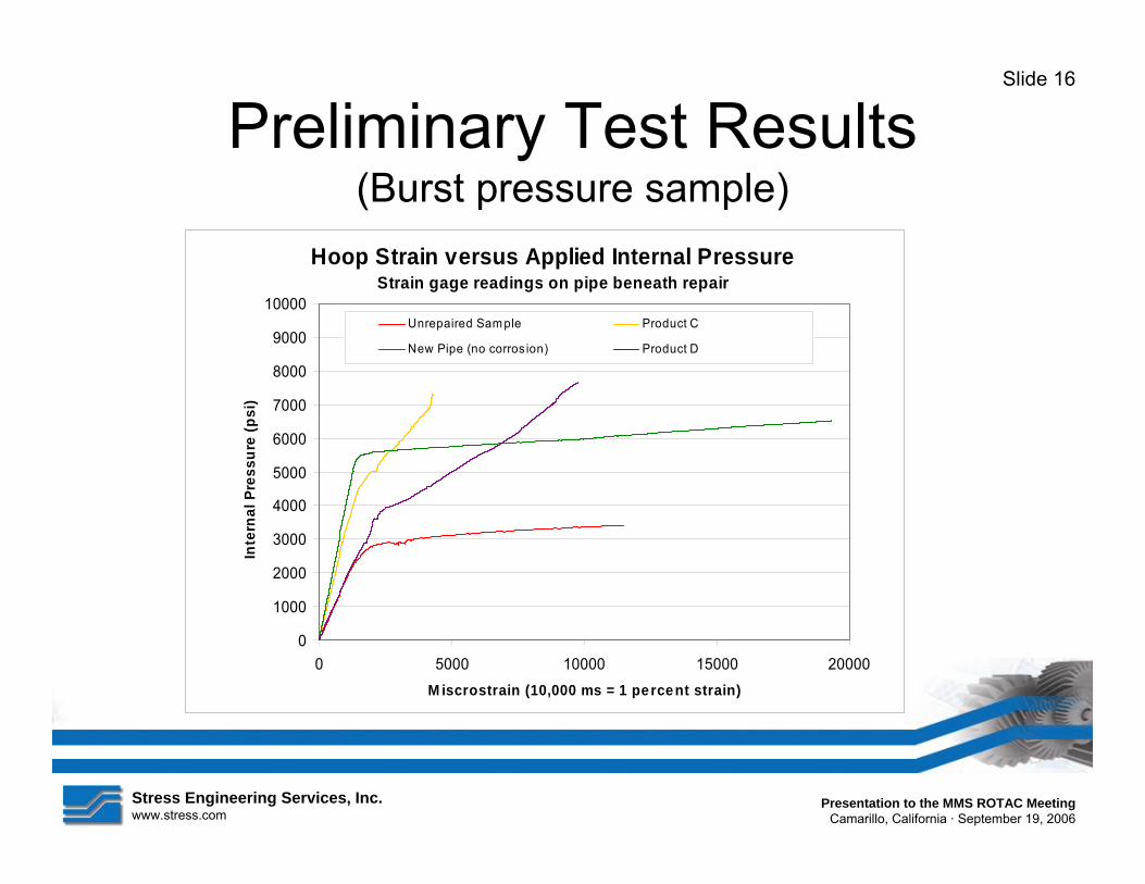

Stress Engineering Services Inc wwwstresscom
Presentation to the MMS ROTAC Meeting Camarillo California middot September 19 2006
Slide 18
Preliminary Test Results (Bending load sample)
Bending Strain versus Applied Bending Load Strain gage readings on pipe beneath repair
0
10000
20000
30000
40000
50000
60000
70000
80000
90000
0 2000 4000 6000 8000 10000 12000 M iscrostrain (10000 ms = 1 pe rce nt strain)
Ben
ding
Loa
d (k
ips)
Unrepaired Sample Product C
New pipe (no corrosion) Produect D
Stress Engineering Services Inc wwwstresscom
conditions
Slide 19
Repair System Development bull Integrating riser loads bull Expected results for the different load
requirements ndash Internal pressure ndash Axial tension ndash Bending
bull Essential elements relative to design repair requirements
bull Consider riser loads subject to API RP 1111 design stress limits
bull Addressing and qualifying potential upset
Presentation to the MMS ROTAC Meeting Camarillo California middot September 19 2006
Stress Engineering Services Inc Presentation to the MMS ROTAC Meeting wwwstresscom Camarillo California middot September 19 2006
Slide 20
Path Forward Activities
Under MMS-OTRC Sponsorhip Composite Repair Methods for Steel Pipes (PR 558-39300 - Dr Ozden O Ochoa)
the following research tasks are underway
bull Implement computational FEA models to validate tests bull Identify amp demonstrate ldquostructurally optimizedrdquo composite
repair concept bull Develop guidelines for MMS with regards to using
composite materials to repair offshore risers

Stress Engineering Services Inc wwwstresscom
conditions
Slide 19
Repair System Development bull Integrating riser loads bull Expected results for the different load
requirements ndash Internal pressure ndash Axial tension ndash Bending
bull Essential elements relative to design repair requirements
bull Consider riser loads subject to API RP 1111 design stress limits
bull Addressing and qualifying potential upset
Presentation to the MMS ROTAC Meeting Camarillo California middot September 19 2006
Stress Engineering Services Inc Presentation to the MMS ROTAC Meeting wwwstresscom Camarillo California middot September 19 2006
Slide 20
Path Forward Activities
Under MMS-OTRC Sponsorhip Composite Repair Methods for Steel Pipes (PR 558-39300 - Dr Ozden O Ochoa)
the following research tasks are underway
bull Implement computational FEA models to validate tests bull Identify amp demonstrate ldquostructurally optimizedrdquo composite
repair concept bull Develop guidelines for MMS with regards to using
composite materials to repair offshore risers