assembly of interference fits - dspace@mit home
TRANSCRIPT

ASSEMBLY OF INTERFERENCE FITS
BY IMPACT AND CONSTANT FORCE METHODS
by
CRAIG C. SELVAGE
S.B., Massachusetts Institute of Technology
(1978)
SUBMITTED IN PARTIAL FULFILLMENT
OF THE REQUIREMENTS FOR THEDEGREE OF
MASTER OF SCIENCE
AT THE
MASSACHUSETTS INSTITUTE OF TECHNOLOGY
JUNE, 1979
Signature of Author .
Approved by ... ..
Department of MechanicaYEngineer'ing, Mar'11, 1979
'-- ·' ' '- ~'" Te/jhnical Supervisor, CSDL
Certified by .Thesis Supervisor
Accepted by . .Chairman, Department Committee on Graduate Students
ARCHIVESr".....,;;;,-.; ,T S iNSc.. . L T
-
OF TECHNOLOGY
JUL 20 1979
LIBRARIES-

ASSEMBLY OF INTERFERENCE FITS BY IMPACT AND CONSTANT FORCE METHODS
by
CRAIG C. SELVAGE
Submitted to the Department of Mechanical Engineering
on May 11, 1979 in partial fulfillment of the requirements
for the degree of Master of Science
ABSTRACT
This thesis investigates the assembly of interference fits by the two basic
methods. The parts may be pressed together quasi-statically, under a constant load,
or be driven into place with a series of impacts.
Wlhen the parts are pressed together, the important consideration is the sta-
tic insertion force. Handbook formulas give an approximate value for the insertion
force because the coefficient of friction is not known with certainty, and the as-
sumed constant contact pressure is altered by the axial force through the Poisson
effect.
This thesis accounts for the Poisson effect, and shows that it becomes an im-
portant consideration when the product of Poisson's ratio, coefficient of friction,
and the contact length to interference diameter ratio exceeds 0.1.
The residual axial stresses resulting from assembly forces are analyzed in
detail, and the minimum energy which must be supplied to begin insertion is calcu-
lated.
An approximate energy analysis of the insertion of an interference fit by an
impact load is presented. This analysis takes into account the presence of an axial
preload force which might be applied as the impact takes place. Two experiments
show a good correlation between the theory and data for impact by hammer blows.
Thesis Supervisor: Dr. Daniel E. Whitney, Lecturer,
Department of Mechanical Engineering
2
ACKNOWLEDGMENTS
This thesis was prepared at the Charles Stark Draper Laboritory, Inc., with
funding provided by the National Science Foundation grant number APR74 - 18173 A03.
I thank my thesis supervisor, Dr. Daniel E. Whitney for the advice, help,
and discussions he contributed, and Valerie Naves for her help in typing this
document.
3
TABLE OF CONTENTS
TITLE PAGE ..........................................
ABSTRACT ............................................
ACKNOWLEDGMENTS .....................................
TABLE OF CONTENTS ...................................
LIST OF FIGURES .....................................
LIST OF TABLES ......................................
1.0 INTRODUCTION .................................
2.0 INSERTION AND WITHDRAWAL FORCES ..............
2.1 Approximate Equations ..................
2.2 Poisson Effect of Axial Stresses .......
2.3 The Effect of Pressure Concentrations ..
3.0 IMPACT LOADING ...............................
3.1 Axial Stress Distributions in the Loading
3.2 Energy Absorbed in Loading .............
3.3 Quasi-static Impact Model ..............
3.4 Impact Dynamics ........................
4.0 IMPACT EXPERIMENTS ...........................
5.0 CONCLUSIONS AND RECOMMENDATIONS ..............
REFERENCES
4
1
2
3
4
5
6
7
9
10
12
22
28
28
31
40
43
45
49
50
......................................
.........................................................*..................*..................
........-.-.............X...-....-....*.....-................................Process.....
........ .............. -.*..................
...................
...................
........... @.....eeeleeeeeeeeeo·e·e
eeeeeeeloeoee!4eeee
ee·eeeeeeeoeeee·ee
iooeeeeole·eeleeeoe
leooeeeeeeeeeeeoeoo
i·leeeeoe·e·eeeeeoe
®eeeeee·eeeoeee·eel
eeleleeo·eeeeee·eoe
eeeeeeeeeeeoeeeeoee
Process .........
eeooeeeeooeoeoeoooo
ooooeooeeoooo·eoeoe
eooeoeooeeeooooeeeo
oooooeeeooeooleeeee
oooeeoloeeoo·eeeooe
LIST OF FIGURES
Figure Page
2.1 Possible axial loads ............................................. 14
2.2 Forces Acting on a thin section of inner cylinder ............... . 15
2.3 Forces acting on inner and outer cylinders ....................... 16
2.4 Forces acting on inner and outer cylinders ....................... 19
2.5 Poisson effect of axial stresses ................................. 23
2.6 Interference pressure for a short collar fit onto a long shaft ... 24
2.7 Interference fit studied by Rankin ............................... 25
2.8 Comparison of stress distribution based on finite-element
analysis and approximate analysis ................................ 26
3.1 Interference fit continuum model ................................. 29
3.2 Axial stresses in a loaded interference fit ...................... 30
3.3 Unloading of a fit with infinite friction ........................ 30
3.4 Residual axial stresses in an unloaded interference fit with
infinite friction ................................................ 32
3.5 Allowing slippage to occur between the cylinders ................. 33
3.6 Residual axial stresses in an unloaded interference fit,
final equilibrium ................................................ 34
3.7 Axial stress distribution for an arbitrary axial load ............ 35
3.8 Axial stress functions for the inner cylinder .................... 37
3.9 Change in axial stress when the cylinders are allowed to slip .... 39
3.10 The effect of preload force on threshold energy .................. 41
3.11. Percent of the threshold energy which is frictional work ......... 42
4.1 Results of impact experiments .................................. 47
5
LIST OF TABLES
Table Page
2.1 Insertion force equations including Poisson effect ............... 20
2.2 Withdrawal force equations including Poisson effect .............. 21
4.1 Specifications of interference fits used in experiments .......... 46
6

1.0 INTRODUCTION
The analysis presented in this thesis was developed in support of research on
industrial assembly. Of fundamental importance is the study of parts mating
science. The basic purpose of parts mating science is to understand the phenomena
which occur as parts are assembled or mated. This requires the construction of
mathematical models which describe the geometric and force relationships as the
parts are assembled.
An analysis of the insertion of a round peg into a hole with a relative clea-
rance has yielded theories which describe the conditions under which jamming or
wedging can be avoided during the assembly process. Guided by this analysis, a de-
vice called a Remote Center Compliance has been developed which allows rapid and
jam-free insertion of close clearance parts having chamfers 2 .
This thesis investigates the assembly of parts having a negative clearance,
called interference, press, or force fits. This type of fit is commonly used for
assembling bearings, attaching gears or sprockets to shafts, inserting dowel pins
into holes, and holding bushings into housings. Often they are used in place of
splines, keyways, and fasteners, permitting a simpler, less costly design, with im-
proved stress distribution.
There are two general methods of interference fit assembly. The parts may
be pressed together quasi-statically, under constant force, or driven into position
using a series of impacts. Unfortunately, from the assembly point of view, the
force required to press together an interference fit ranges from several to many
thousands of pounds. An assembly machine or robot may not have sufficient load ca-
pacity to perform the insertion by directly pressing the parts together. Thus,
assembly by impact (such as with a pneumatic hammer) promises to be an attractive
alternative.
This research provides a method for calculating the insertion force associa-
ted with a particular interference fit, and presents an approximate analysis for
predicting the insertion distance provided by a given hammer blow. Useful for the
design of interference fits are equations for withdrawal, or holding force, which
7
in general, differs from the insertion force. The analysis of assembly by impact
may also be used to determine the impact absorbing capability of an interference fit
subjected to service loads which are impulsive in nature.
8

2.0 INSERTION AND WITHDRAWAL FORCES
An interference fit is obtained by forcing a shaft into a hole with a
slightly smaller diameter. To accommodate this interference, the shaft must
contract radially, and the hole expand, producing a radial contact stress at the
interface. This radial stress is referred to in the literature as an "interference
pressure", and this term is used here. In general, the interference pressure varies
along the length of contact, and changes in response to the external loading of the
assembled interference fit.
The force necessary to produce relative sliding between the parts (insertion
or withdrawal force), is the product of the coefficient of friction and the surface
integral of the contact pressure.
The most simple case to consider is that of two interfering concentric
cylinders of equal length, where the inner cylinder is fully enclosed by the outer.
In the absence of axial stresses, each cylinder is in a state of plane stress, and
the interference pressure is constant along the length of contact. The application
of an axial insertion force, however, will produce a variation in the interference
pressure due to the Poisson effect of axial stresses.
The traditional treatments of interference fits found in texts and hand-
books 3 - 7 always assume a constant interference pressure (equal length fully engaged
cylinders), and neglect the Poisson effect of axial stresses. Thus, these
equations only approximate the case of a hub fit on a long shaft, or a partially
inserted shaft, where the interference pressure forms a concentration at the edges
of contact. In these cases where edge discontinuities exist, there are no exact
analytic solutions, so finite element methods 8 1 1 are used when the interference
pressure distribution must be known with accuracy. The handbook equations are
usually of practical value, however, because the uncertainty due to the
coefficient of friction is likely to be larger than the error resulting from the
constant pressure assumption.
9
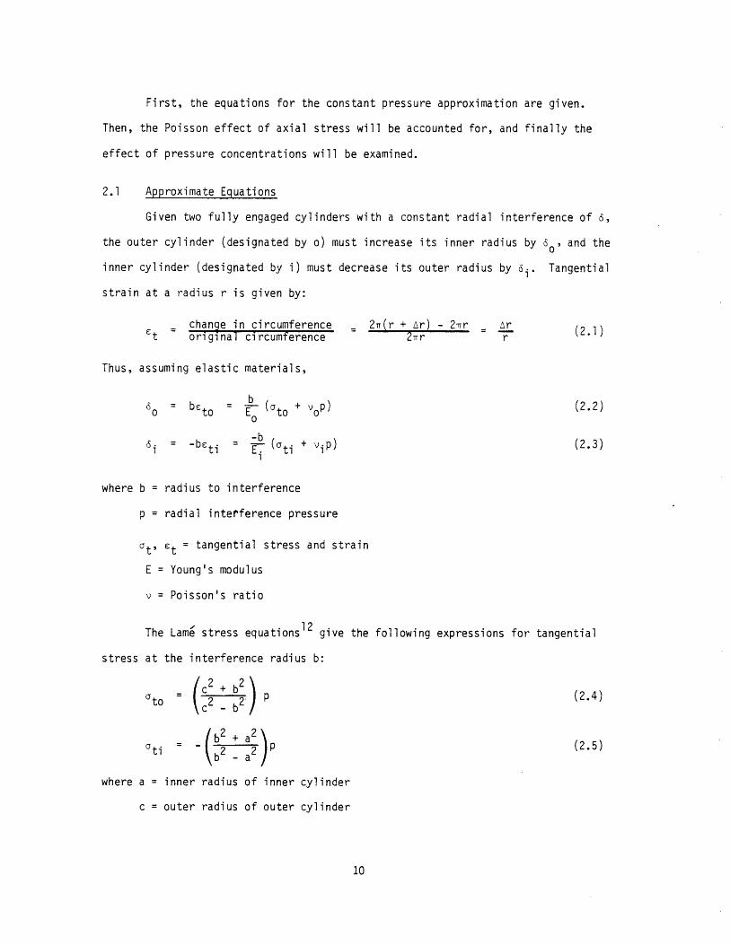
First, the equations for the constant pressure approximation are given.
Then, the Poisson effect of axial stress will be accounted for, and finally the
effect of pressure concentrations will be examined.
2.1 Approximate Equations
Given two fully engaged cylinders with a constant radial interference of a,
the outer cylinder (designated by o) must increase its inner radius by 60, and the
inner cylinder (designated by i) must decrease its outer radius by ai . Tangential
strain at a radius r is given by:
change in circumference 27(r + r) - 2.r r1)t original circumference r r
Thus, assuming elastic materials,
b6 b= to = E (to+ op) (2.2)
i = -b=ti E (ati + viP) (2.3)
where b = radius to interference
p = radial interference pressure
at' c t = tangential stress and strain
E = Young's modulus
v = Poisson's ratio
The Lame stress equationsl2 give the following expressions for tangential
stress at the interference radius b:
ato c2 _ 2 (2.4)
ati /b2 a2
where a = inner radius of inner cylinder
c = outer radius of outer cylinder
10

Substituting these into Eqs. (2.2) and (2.3), and utilizing the constraint 6 = 6i
+ 60,
6 o(02 o)=c2 _ b2
(2.6)
Solving for the interference pressure,
p = 1/2 ()Eb
(2.7)
where
2Ee (2.8)
1 (c 2 + b 2Eo c2 _ )2
2 2+ vi + a0/ Lib2 -a
If the cylinders have the same material properties, E and v,
EEe
(2.9)b2
a2 c2 b2 jb -a
In addition, if a = o (solid shaft),
b2
Ee = (1- -)Ee c
(2.10)
By assuming the interference pressure remains constant in the presence of
axial stresses, the insertion/withdrawal force, F, equals the product of interference
pressure, contact area, and coefficient of friction.
(2.11)F = p(27bL)p
11
Ei 2 a
where L = length of contact
= coefficient of friction
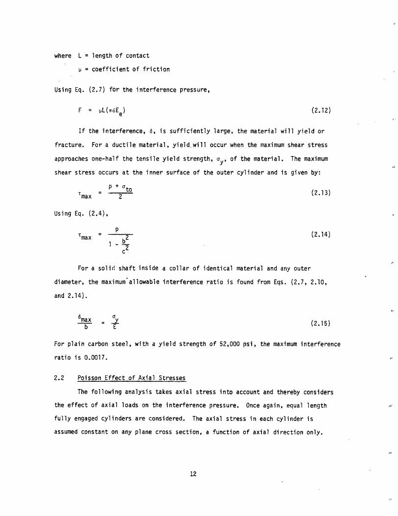
Using Eq. (2.7) for the interference pressure,
F = PL(r6Ee) (2.12)
If the interference, 6, is sufficiently large, the material will yield or
fracture. For a ductile material, yield.will occur when the maximum shear stress
approaches one-half the tensile yield strength, y, of the material. The maximum
shear stress occurs at the inner surface of the outer cylinder and is given by:
P + top'r~~~~~~~~~~~ + at(2.13)max 2
Using Eq. (2.4),
P
max - (2.14)b
1 -
c2
For a solid shaft inside a collar of identical material and any outer
diameter, the maximum allowable interference ratio is found from Eqs. (2.7, 2.10,
and 2.14).
6 ax6max = y (2.15)b E
For plain carbon steel, with a yield strength of 52,000 psi, the maximum interference
ratio is 0.0017.
2.2 Poisson Effect of Axial Stresses
The following analysis takes axial stress into account and thereby considers
the effect of axial loads on the interference pressure. Once again, equal length
fully engaged cylinders are considered. The axial stress in each cylinder is
assumed constant on any plane cross section, a function of axial direction only.
12
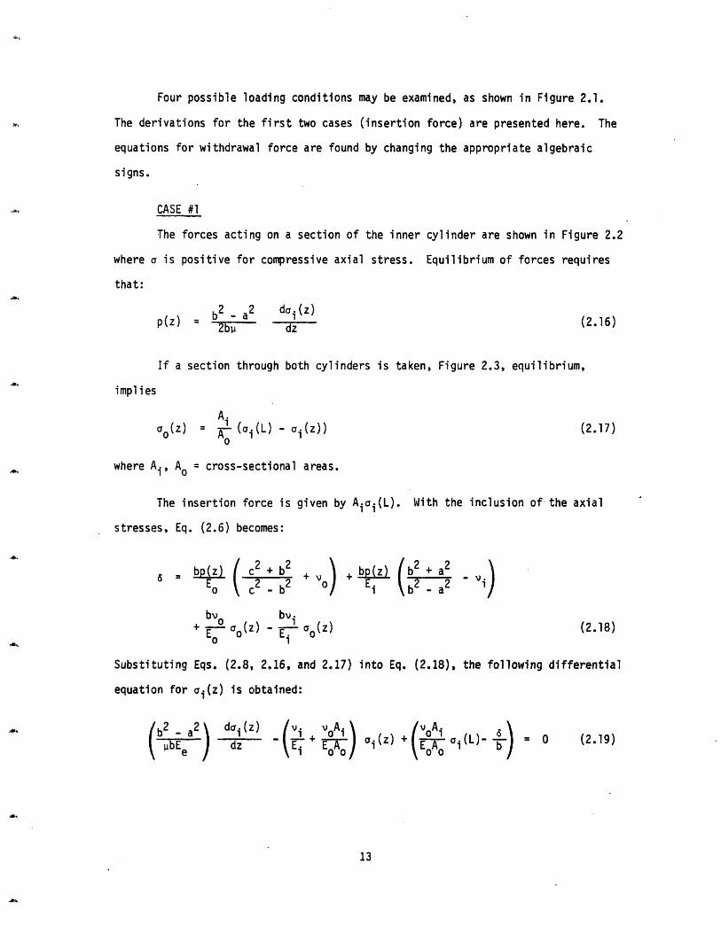
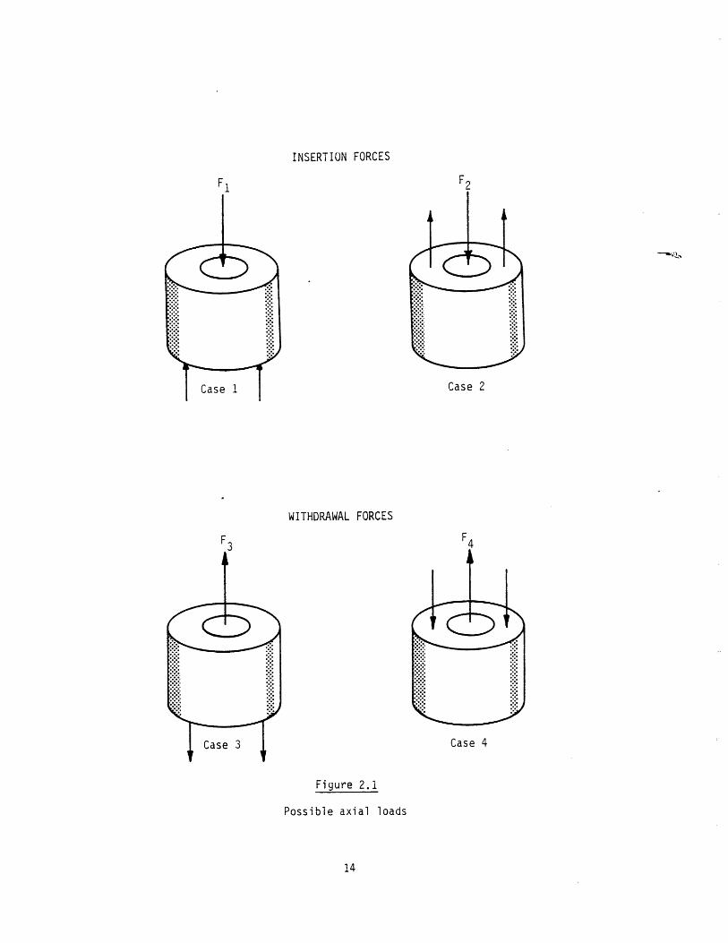
Four possible loading conditions may be examined, as shown in Figure 2.1.
The derivations for the first two cases (insertion force) are presented here. The
equations for withdrawal force are found by changing the appropriate algebraic
signs.
CASE #1
The forces acting on a section of the inner cylinder are shown in Figure 2.2
where a is positive for compressive axial stress. Equilibrium of forces requires
that:
b2 a2 do i (z)p(z) : -- '-z (2.16)
If a section through both cylinders is taken, Figure 2.3, equilibrium,
implies
Ai
O(z) A (ai(L) - ai(z)) (2.17)
where A i, Ao = cross-sectional areas.
The insertion force is given by Aai(L). With the inclusion of the axial
stresses, Eq. (2.6) becomes:
bp(z) ( + b2 +bp(z) 6 E \c2 -b2 V 2 2 vi
bYo b i (2.18)
EO aO(Z) E- °o(Z) (2.18)0 1
Substituting Eqs. (2.8, 2.16, and 2.17) into Eq. (2.18), the following differential
equation for oi(z) is obtained:
/b2 a2\ da.i(z) v. i A vo.
t i bEe ) -3 - 1 W i(Z) + O ai(L)-b) O (2.19)
13
INSERTION FORCES
F2F1
Case 2
WITHDRAWAL FORCES
F4F3
Case 4
Figure 2.1
Possible axial loads
14
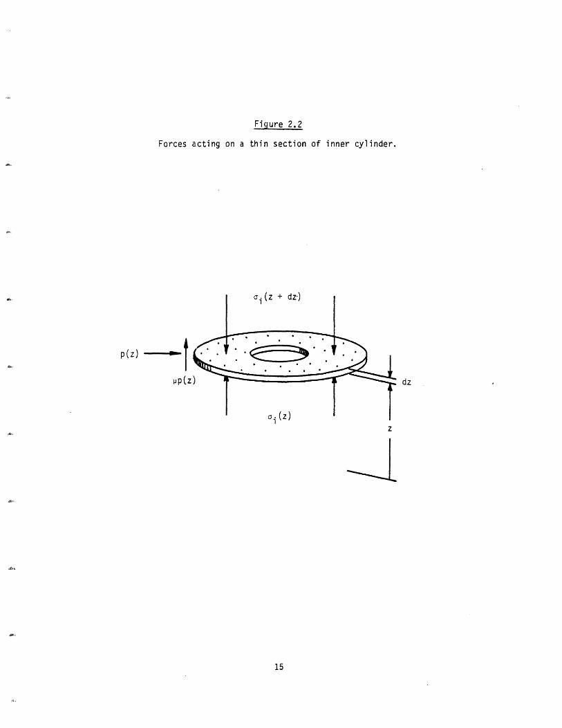
Figure 2.2
Forces acting on a thin section of inner cylinder.
, . ·
p(z) _ l
pp (z
z
15
dz!
I

Figure 2.3
Forces acting on inner and outer cylinders.
ai(L)
, (7
Case 1
16
I
"0\-/
---
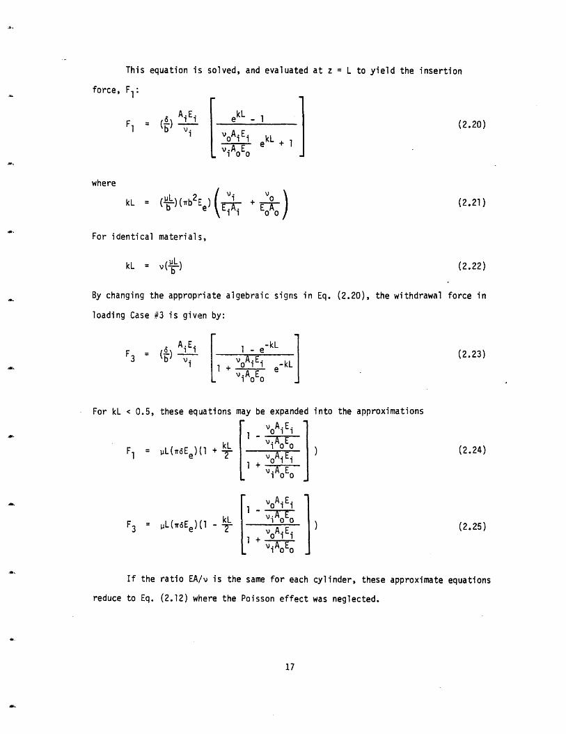
This equation is solved, and evaluated at z = L to yield the insertion
force, F1:
AiEiF1 = (.) i
vi
(2.20)
kL + 1
where
2 Vi + VO )kL = (L-L)(Trb2E ( o -ob e\ TE 0 A0 J'i
For identical materials,
kL = v(")
By changing the appropriate algebraic signs in Eq. (2.20), the withdrawal force in
loading Case #3 is given by:
F3 b= (.) 1i + oAiEi e-kL
1 ViAoEo
(2.23)
For kL < 0.5, these equations may be expanded into the approximations
F1 = uL(T6Ee)(1 + 2
F3 = pL(*6Ee)(1 - -
voAiEiI iAoE o
viAoEo
voAiEiviAo E
1+iAEO
If the ratio EA/v is the same for each cylinder, these approximate equations
reduce to Eq. (2.12) where the Poisson effect was neglected.
17
(2.21)
(2.22)
) (2.24)
(2.25)
i
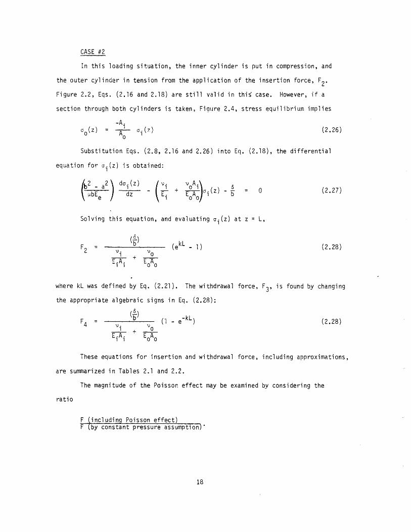
CASE #2
In this loading situation, the inner cylinder is put in compression, and
the outer cylinder in tension from the application of the insertion force, F2.
Figure 2.2, Eqs. (2.16 and 2.18) are still valid in this case. However, if a
section through both cylinders is taken, Figure 2.4, stress equilibrium implies
-A.
O(Z) = A ai(z7) (2.26)
Substitution Eqs. (2.8, 2.16 and 2.26) into Eq. (2.18), the differential
equation for oi(z) is obtained:
b dz ( E. + E - 0 (2.27)-4bEe a da~dz~z) E1 E0A0 i b
Solving this equation, and evaluating ai(z) at z = L,
(6)F2 = (ek L 1) (2.28)
2 V Vo1 0
EA + E-AEiAi + o
where kL was defined by Eq. (2.21). The withdrawal force, F3, is found by changing
the appropriate algebraic signs in Eq. (2.28):
F b ( - e- kL ) (2.28)
4 Vi vOEiA i EoA-
These equations for insertion and withdrawal force, including approximations,
are summarized in Tables 2.1 and 2.2.
The magnitude of the Poisson effect may be examined by considering the
ratio
F including Poisson effect)F (by constant pressure assumption)'
18
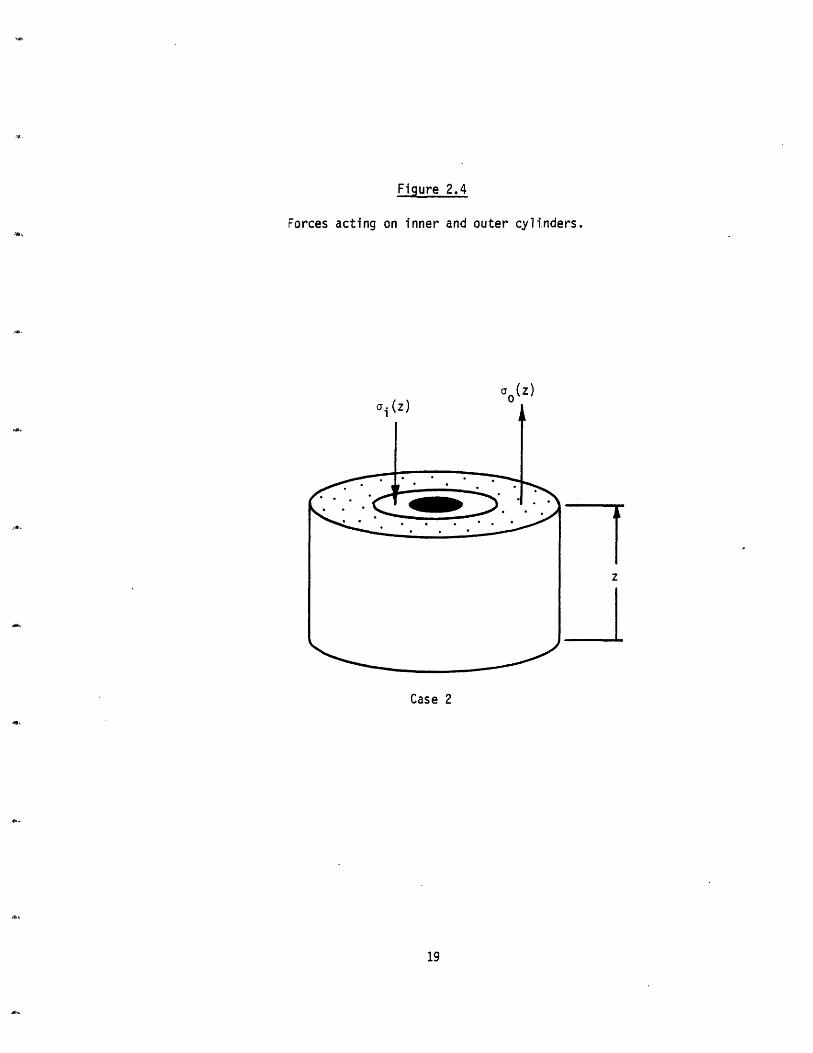
Figure 2.4
Forces acting on inner and outer cylinders.
o, (z)
Case 2
19
z
z
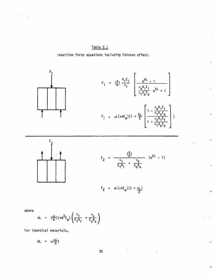
Table 2.1
Insertion force equations including Poisson effect.
AiEF1 = L( e)(v
Fl "L(1T(Ee)( 1
F2..
EiAi
[
ekL _
voAiE i
v100AoEo
1 -v°Ai Ei1 viA E°
2 vA i Ei1 + vA E
(ekL - 1)
V0+ EA
0 0
F2 IIL(r6tEe)(1 + kL)2
where
kL = (-L)(wb2Ee) E V -Ei i0
For identical materials,
kL = v( L )
b
20
I I
F.
t
m mmm~mm Jm me
S
_m _ m _i
_ _
F1
Ir
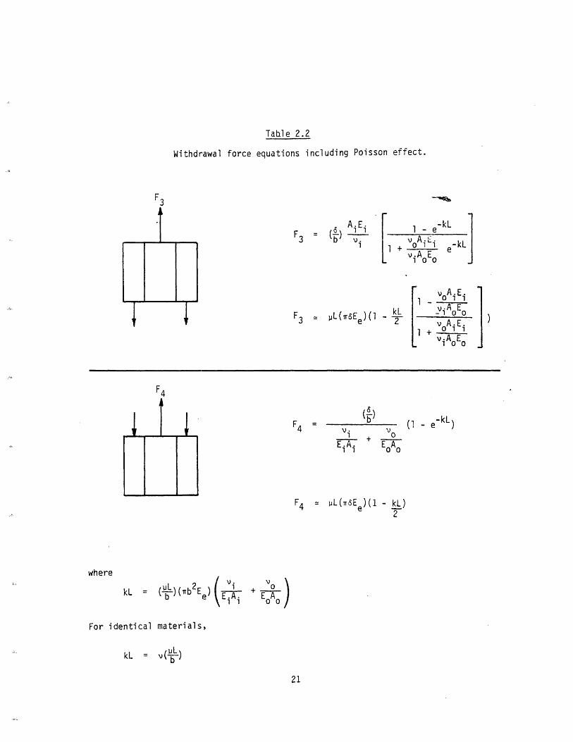
Table 2.2
Withdrawal force equations including Poisson effect.
F3
F = A.Ei
L7ul-e kL
.Ai E e-kLJi AoEo
v A iE i
- A E
F3 : L(aEe )(1 kL -- i v3 = e 2 ~~~voAi EiI v A i 0
F4 = V.vi
EiA i
+ OE0 A0
F4 = PL(iaEe)(1 - kL)Tw
where
kL = (iL)(b2E )b InViAi1 j + E)
oA
For identical materials,
kL = v( )b
21
F4
* t L
Li
(1 - - k L
V+-1

This ratio is plotted in Figure 2.5 for cylinders of identical material
properties. If the contact length to interference diameter ratio, L/2b, is two,
for example, the Poisson effect is bounded by a maximum force increase of 13%
(insertion by method 2) and a maximum force decrease of 11% (withdrawal method 4),
where Poisson's ratio = 0.3 and the friction coefficient = 0.2.
Thus, for interference fits having low length to diameter ratios, the Poisson
effect may be neglected in comparison with the uncertainties regarding the friction
coefficient.
2.3 The Effect of Pressure Concentrations
The previous analysis assumed that with no axial stresses, the interference
pressure would be the same at all points of contact. This is a valid assumption
for fully engaged cylinders of equal length. However, in every other case, there
will be a stress concentration where a shaft enters a hole and where a shaft ends
in a hole. Far from these points of discontinuity, if the contact length is
sufficiently long, the interference pressure approaches the constant value given
by Eq. (2.7). Thus, in determining insertion and withdrawal forces, the equal
length cylinder assumption would become increasingly valid as the contact length
to interference diameter ratio increases.
Previous studies have focused primarily on finding the contact stresses
resulting from mounting a short frictionless cylindrical collar onto a solid shaft
of infinite length. Rankin 1 3 measured the deformation of a shaft upon which a
short hub was mounted and then determined what equivalent uniform band of pressure
would be required to account for these measured radial displacements.
tlore recent studies 8 1 1 have used finite element methods to determine the
actual pressure distribution for collars of various lengths and thicknesses. The
general trend for cylinders of identical material is shown in Figure 2.6.
The interference fit problem studied by Rankin has been analyzed using a
finite element computer program l0. The dimensions are shown in Figure 2.7, while
the pressure distribution is plotted in Figure 2.8.
22

Figure 2.5
Poisson effect of axial stresses
0 0.5 1.0 1.5 2.0 2.5
( upL/b )
23
(cJ
OL
U-
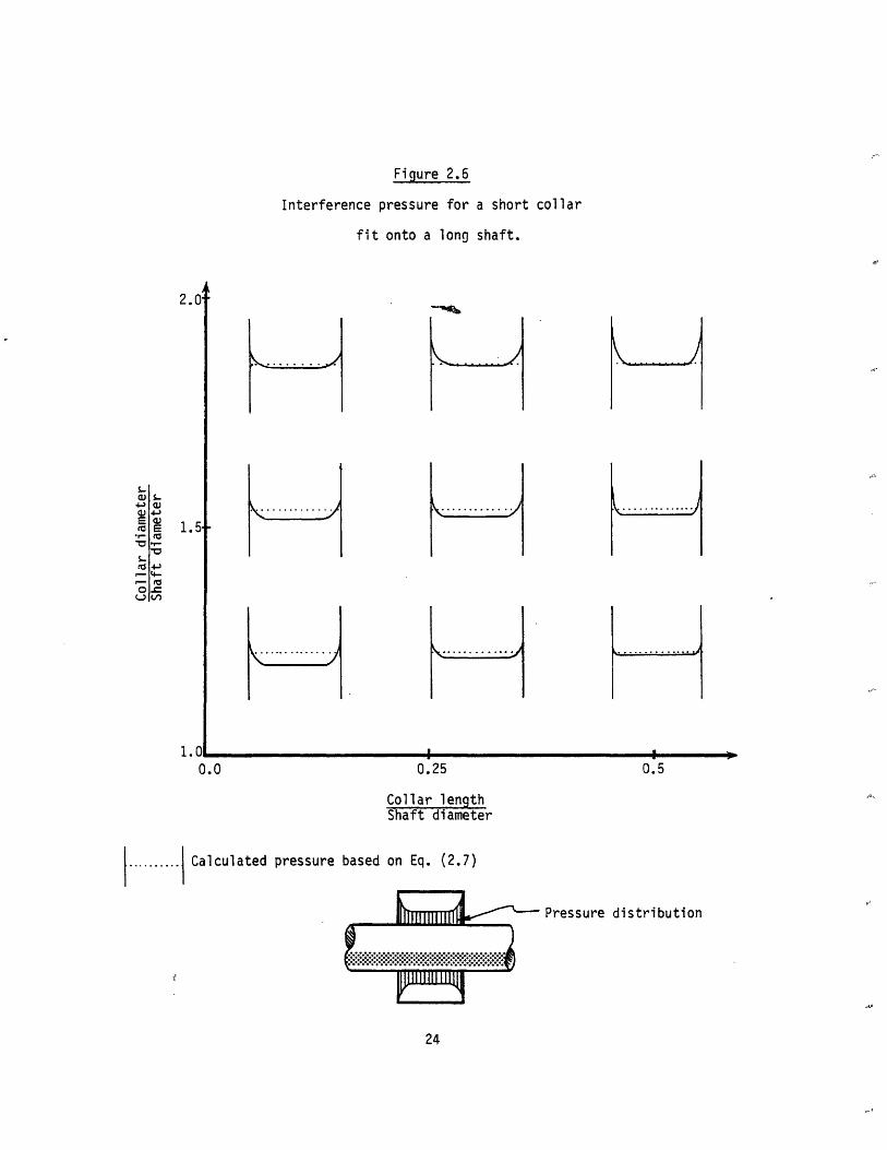
Figure 2.6
Interference pressure for a short collar
fit onto a long shaft.
2.0'
1.5
1 f
0.0 0.25 0.5
Collar lengthShaft diameter
.......... Calculated pressure based on Eq. (2.7)
Pressure distribution
:·····t·::::·::LY:::::
24
S-a)
Etz4-a4-
MV:
5
E
-W4 1wS
U1
L
.
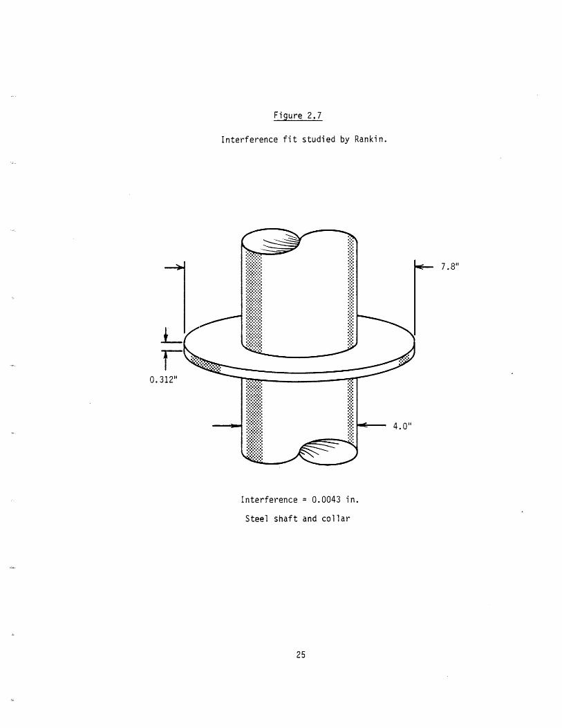
Figure 2.7
Interference fit studied by Rankin.
Interference = 0.0043 in.
Steel shaft and collar
25
7.8"
0.
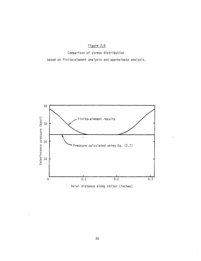
Figure 2.8
Comparison of stress distribution
based on finite-element analysis and approximate analysis.
0.1 0.2 0.3
Axial distance along collar (inches)
26
40
ur
m 30
q)g)
a 20UC)1
aj 10-4-.I
0

The insertion force is found by measuring the area under the curve:
FI = (27b) .r pdz (2.29)
Using the constant pressure assumption, Eq. (2.12), one predicts an insertion
force 16% less than if Figure 2.8 and Eq. (2.29) are used (axial stress Poisson
effect is negligable). Thus, even in this case where there is a considerable devia-
tion from constant pressure, the predicted insertion force is within the margin of
uncertainty in the coefficient of friction. Furthermore, since the contact length
to interference diameter ratio (L/2b) was 0.078, extremely small, and accuracy im-
proves as L/2b increases, this study indicates that in determining insertion and
withdrawal forces, end effects may be neglected in practical applications.
27

3.0 IMPACT LOADING
This section investigates the behavior of interference fits subject to the
forces of impact. The emphasis here will be on the assembly of interference fits
by impatt methods. The same concepts may be used in evaluating the impact absorbing
capability of fits subject to service loads which are impulsive in nature.
Throughout the analysis, the following assumptions are made:
1) The interference pressure is constant along the length of contact
2) Relative sliding between the parts is governed by Coulomb friction
3) Axial stresses change in the axial direction only
3.1 Axial Stress Distributions in the Loading Process
Given the above assumptions, an interference fit may be modeled as two sets
of spring-block chains coupled by Coulomb friction, as shown in Figure 3.1. Quasi-
static loading is considered, so that inertia effects may be ignored.
When the static insertion force, FI, is applied (given by Eq. (2.12)), the
axial stress in each cylinder decreases linearly with depth, as shown in Figure 3.2.
If the insertion force is now removed from the loaded cylinders, residual axial
stresses will result. In addition, slippage between the parts will occur over cer-
tain portions of the contact area.
First, consider the removal of the insertion force assuming there is infinite
friction between the parts (no slippage). The forces acting on a section of incre-
mental thickness during initial loading and final equilibrium are shown in Figure
3.3. In order to satisfy the constraint
aiA i + aiA 0 = 0 (3.1)
at all depths, the cylinders undergo uniform expansion until the resulting elonga-
tion of each incremental section is given by:
e = FI dz
EiAi + EoA (3.2)
28
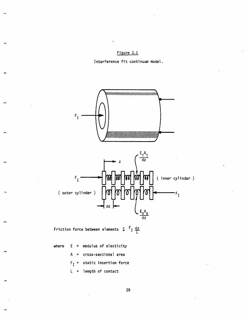
Figure 3.1
Interference fit continuum model.
FI-
E.A.
FI ( inner cylinder )
( outer cylinder )
Friction force between elements
F I
F dzI
where E = modulus of elasticity
A = cross-sectional area
FI = static insertion force
L = length of contact
29
*g,
dz
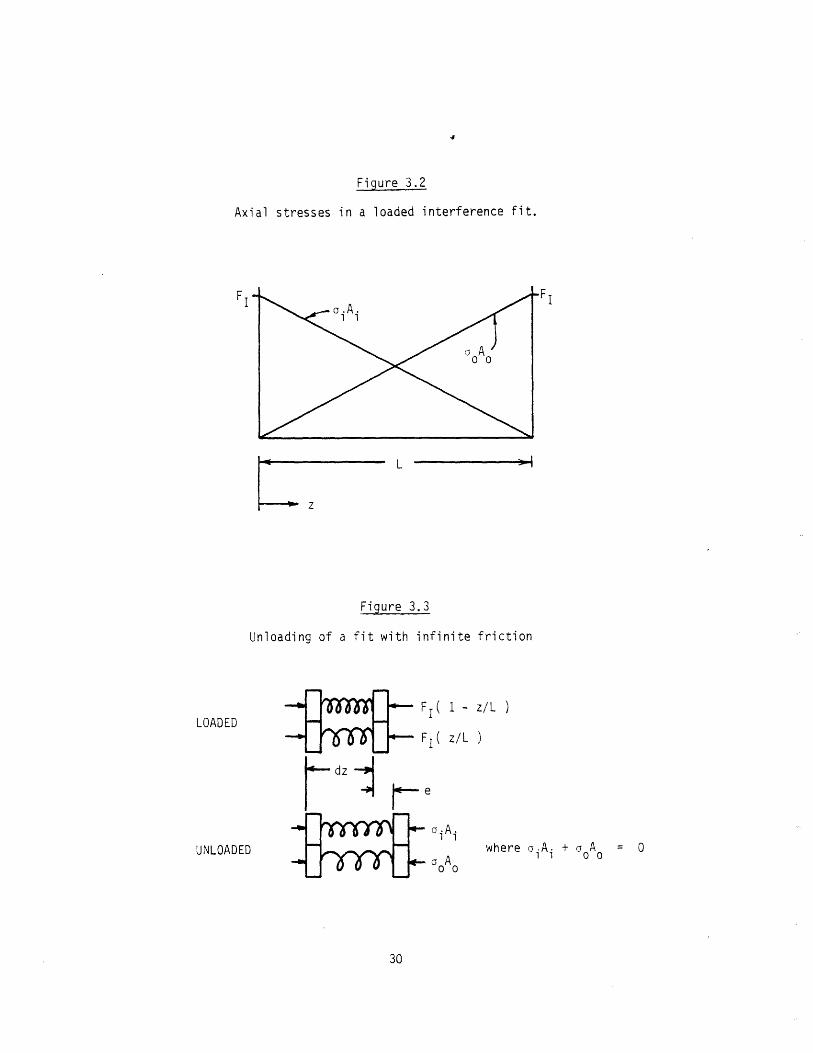
Figure 3.2
Axial stresses in a loaded interference fit.
L
I
-~1
Z
Figure 3.3
Unloading of a fit with infinite friction
F I (
F (
- z/L )
z/L )
aiA i
Ao o
where oA. + A = 0
30
FI
LOADED
UNLOADED
e
Thus, the axial stress in each cylinder is reduced by a constant amount:
ao i= EiAi FE A + E A At (3.3)EiAi + E0oAo Ai
,oo = EoAo F1 (3.4)
EiAi + EoAo Ao
The resulting stress distribution with the insertion force removed (infinite fric-
tion) is shown in Figure 3.4. At all depths, where one cylinder is in compression,
the other is in a corresponding state of tension.
At this point, slippage has not been allowed. This requirement implies that
the ends of the cylinders are held together with infinite friction, while all inte-
rior points exert the maximum friction, FIdz/L. The final stress equilibrium is
found by allowing successive elements to slip, starting at the endpoints of the cy-
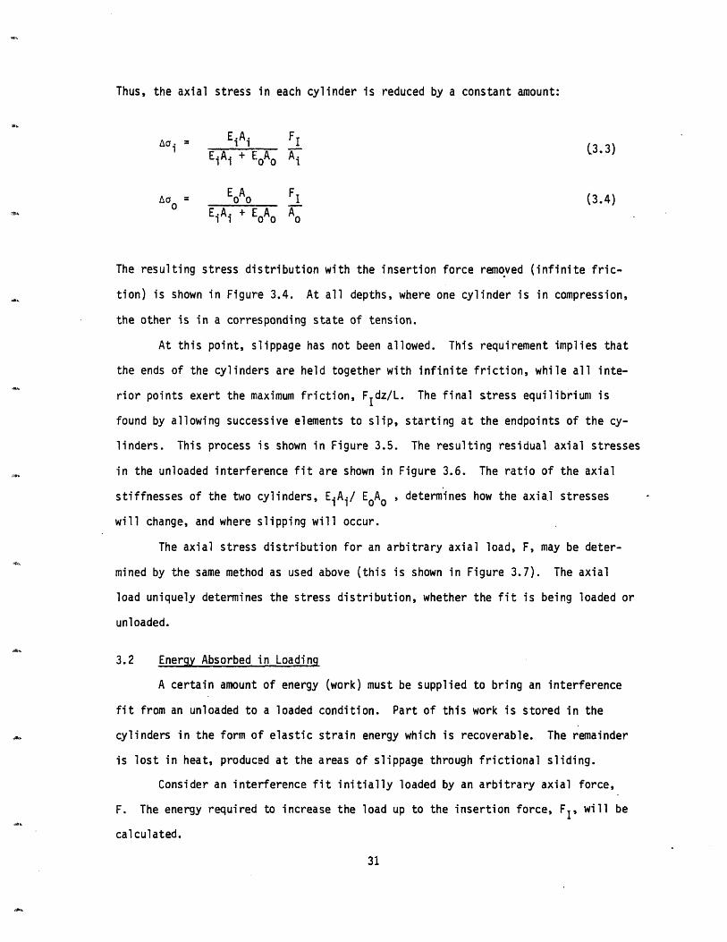
linders. This process is shown in Figure 3.5. The resulting residual axial stresses
in the unloaded interference fit are shown in Figure 3.6. The ratio of the axial
stiffnesses of the two cylinders, EiAi/ EA o , determines how the axia.l stresses
will change, and where slipping will occur.
The axial stress distribution for an arbitrary axial load, F, may be deter-
mined by the same method as used above (this is shown in Figure 3.7). The axial
load uniquely determines the stress distribution, whether the fit is being loaded or
unloaded.
3.2 Energy Absorbed in Loading
A certain amount of energy (work) must be supplied to bring an interference
fit from an unloaded to a loaded condition. Part of this work is stored in the
cylinders in the form of elastic strain energy which is recoverable. The remainder
is lost in heat, produced at the areas of slippage through frictional sliding.
Consider an interference fit initially loaded by an arbitrary axial force,
F. The energy required to increase the load up to the insertion force, FI, will be
calculated.
31

Figure 3.4
Residual axial stresses in an unloaded interference fit
with infinite friction.
ao.A. Aa AIi 0
FI
X.
x
J
--
32
FI
CUUUCCIC
C
CCLO
LI-
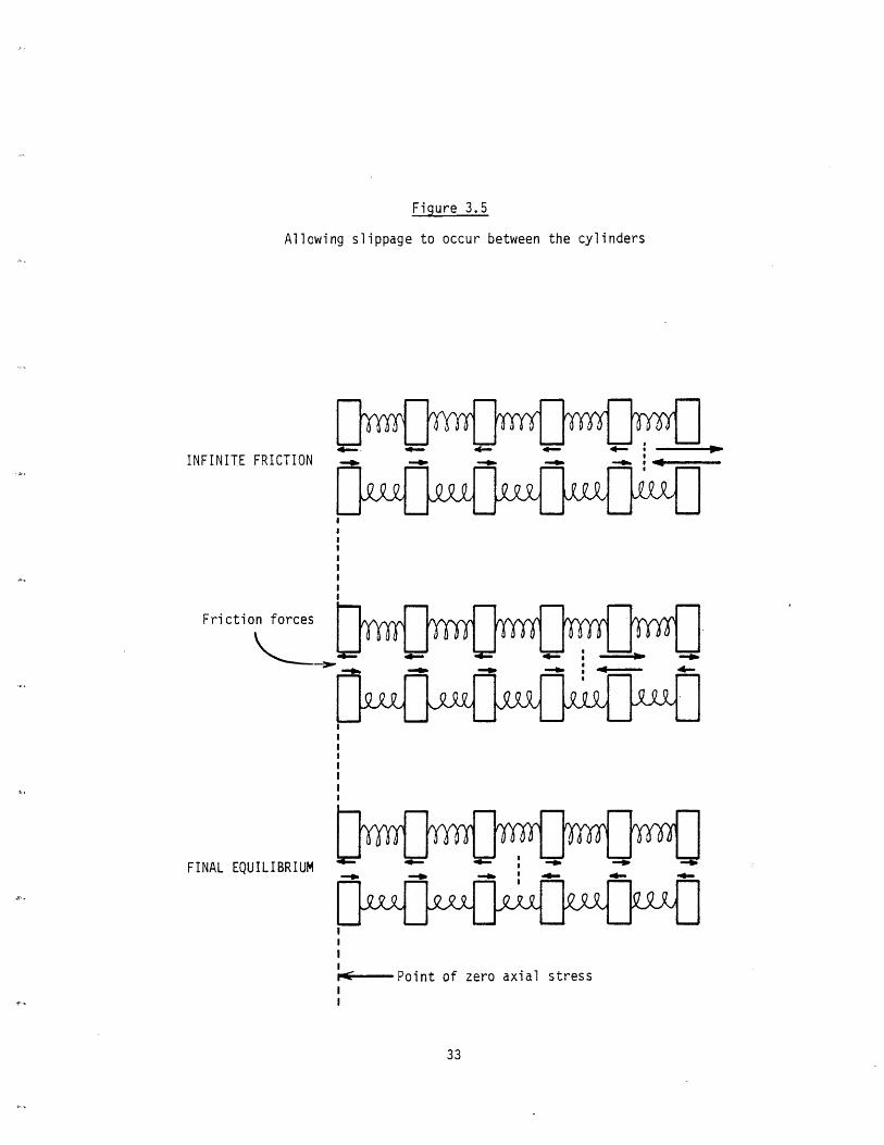
Figure 3.5
Allowing slippage to occur between the cylinders
INFINITE FRICTION
Friction forces
FINAL EQUILIBRIUM
II!
Point of zero axial stressII
33
IIIIII
IIII

Figure 3.6
Residual axial stresses in an unloaded interference fit,
final equilibrium.
34
FI
z0,LJ
CA
Li
I-

Figure 3.7
Axial stress distribution for an arbitrary axial load
( INNER CYLINDER )
35
F
F
¢
z, .
()
o
c:
Z

REQUIRED STRAIN ENERGY
If F (z) is the axial stress function resulting from the application of theI
insertion force, FI, and F(Z) corresponds to an arbitrary load F, where F < FI, the
difference in strain energy is given by:
L 2 2
Us : A/2E F(z) - F(Z )dz
The axial stress functions aFi(Z) and F(Z) for the inner cylinder are specified in
Figure 3.8. A straightforward but tedious integration of Eq. (3.5) using these
stress functions yields an expression for the strain energy absorbed by the inner
cylinder. By replacing EiA i by EoAo , and vice versa, in this equation, the energy
absorbed by the outer cylinder is found. The total strain energy absorbed by both
cylinders is then given by:
U = FI 1 - F +
s 8 I ET
+ 4 | F + 1
EiA i + EA IF E.A.\11 00/ I 1
EA + EoAo FE.A. + E A 1
+ 1
EAo o
+ 1EiA i + EoAo ] oo
The strain energy requirement to bring the interference fit from an
to a fully loaded state is then:
unloaded (F=O)
F2 L8 I 1
8 EiA i
+ 1
EoAo
+ 1
EiA i + EoAo
REQUIRED FRICTIONAL WORK:
If the load on the interference fit is reduced from FI to F, the resulting
axial stress functions corresponding to infinite friction (no slip) may be found as
in section 3.1. When the cylinders are now allowed to slip, in reaching final
36
(3.6)
(3.7)
(3.5)

Figure 3.8
Axial stress functions for the inner cylinder
1 E0 A0a EiAi + EA2 E.A. + E A11 00
b = L - (1
= EiA i
0 0
(1 -FI)
+ 2EiAi a
37
L,V,
-J
x

equilibrium, the stress functions will change only in the places where slipping
occurs. The changes in the axial stress functions may be used to determine the rela-
tive displacement of each cylinder. The energy lost in frictional sliding is given
by:
Uf L F (z) - u(z) I dz (3.8)
where uz) = displacement of inner cylinder when allowed to slip
where u(z) = displacement of inner cylinder when allowed to slip
u0 (z) = displacement of outer cylinder when allowed to slip
The stress functions corresponding to infinite friction, and final equilibrium
are shown in Figure 3.9. When the cylinders are allowed to slip, the axial stress in
each cylinder is changed by the following amount:
a(z) = 2FI z (3.9)A L
where the variable z is defined in Figure 3.9. The resulting displacement is given
by:
Z
u(z) = 1/E l aa(z) dz (3.10)
Substituting in Eq. (3.9), and integrating, the displacement of each cylinder when
allowed to slip is found:
2
u(z) I = (3.11)E.A.L
I u() I Z (3.12)
o o0
Evaluating Eq. (3.8) at the two areas of slippage, using Eqs. (3.11) and (3.12), the
amount of energy lost in frictional sliding is given by:
38
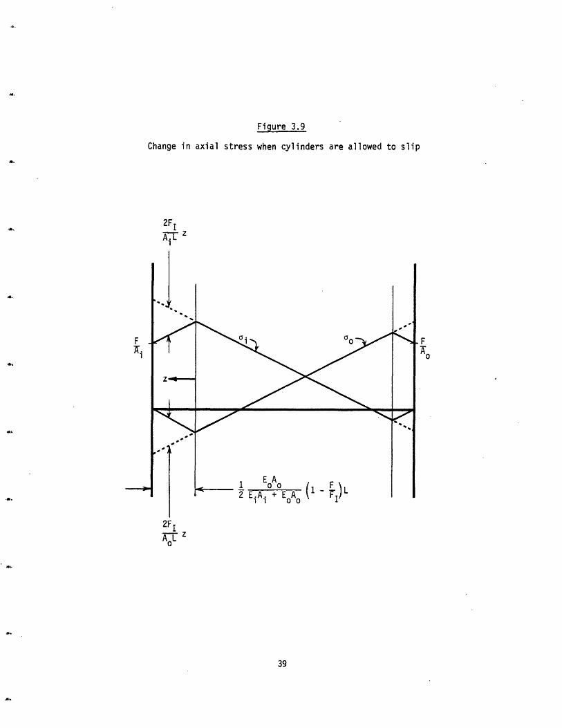
Figure 3.9
Change in axial stress when cylinders are allowed to slip
2F I
A-- z
1 EA
2 EiA i +EA A (1- L'
F
go
2F I
Ao L
39
F

F2 3Uf = FIL 1 F ( 1A + I - 3 (3.13)
24 + FI A E A EiA + EAI 1i Eo+o Ei1 i o )
The total amount of energy required to increase the load on an interference
fit from an arbitrary force, F, to the insertion force, FI, is given by Us + Uf, and
will be called the threshold energy, U.
F L (Ui .A + E A 3 F6 ( I (iA i EoAo i i o o I
+ ___ 1 1 91 - 1 - F + 1 + 1 (3.14)
EiAi + EoAo EiAi EoAo FI EiAi EoAo
The threshold energy plotted as a function of preload force, F, is shown in
Figure 3.10. When the interference fit is initially unloaded (F=0), the threshold
energy is given by:
2U = F L 1 + 1 (3.15)
6 0 EiA EoAo
The fraction of the threshold energy which is frictional work is shown in
Figure 3.11.
3.3 Quasi-static Impact Model
An approximate analysis of the response of an interference fit subjected to
an applied impact load can be made using the threshold energy equations derived
above. The mass of the interference fit is neglected, allowing the impact to be
modeled as time independent, or quasi-static loading. This analysis will determine
what movement (insertion) will occur when an interference fit receives a blow from
a hammer.
Consider a mass, M, having a kinetic energy, ½MV2, at the instant before
40
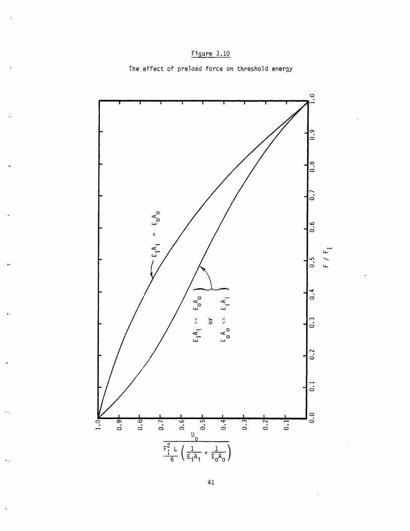
Figure 3.10
The effect of preload force on threshold energy
o
U0
1
EOAO/
41
-L
LL
F L 12E-i+
Figure 3.11
Percent of the threshold energy which is frictional work
0-'-4
Uf / Uo x 100
42
0'Co
LLU-in
o
Ci0
OCo
striking the interference fit. If this kinetic energy is less than the threshold
energy, U, no insertion will take place. If, however, the kinetic energy is
greater than the threshold, conservation of energy implies:
FIAL = UH - U (3.16)
where UH = 4MV2 = kinetic energy of hammer
FI = static insertion force
AL = motion per hit
The threshold energy given by Eq. (3.15) is for concentric cylinders of
equal length. If the inner cylinder (shaft) protrudes a distance L, the the equa-
tion for threshold energy with no preload becomes:
[ 2 [o ) +] (3.17)
If the interference fit has a preload force, F, applied to it as the impact
takes place, conservation of energy implies:
( F - F ) AL = U - U (3.18)
where the threshold energy includes the effect of the preload force, as given
by Eq. (3.14).
Since the mass of the interference fit was neglected in this analysis, one
would expect these results to become increasingly accurate as the mass of the stri-
king object becomes much larger than that of the interference fit.
3.4 Impact Dynamics
A more exact analysis of impact takes into account inertia effects and so
treats the variation of stress and strain at each point in the interference fit as
a function of time. Due to the presence of Coulomb friction, which acts at the
43

interface between the parts, the governing coupled partial differential equations
are nonlinear. The problem is highly complex because of the transmission and reflec-
tion of elastic waves at the frictional boundary, and wave reflection at free sur-
faces. In addition, the applied force must either be completely prescribed, or the
striking mass must be assumed to be rigid.
The special case of a stress pulse applied to an elastic rod of infinite
length bounded by Coulomb friction is the only problem for which an exact analytic
solution has been obtained ' . This is of very limited usefulness, however, since
the transmission of elastic waves through the frictional boundary and into the outer
member has been neglected. A useful method of analysis may be an equivalent linear-
ization method 16 in which the Coulomb friction is modeled as a combination of linear
terms such that the mean square difference between the steady state solutions is
minimized.
44
4.0 IMPACT EXPERIMENTS
Two experiments were performed to test the validity of the quasi-static
analysis presented in section 3.3. In each case, a solid shaft was pressed into a
collar of shorter length so that the shaft protruded from the top. The interfe-
rence fits were placed on the bed of a milling machine in order to provide a rela-
tively stiff surface in comparison with the compliance of the fits themselves. A
hammer was dropped onto the interference fits from various heights, and the resul-
ting insertion per hit was measured.
The hammer was dropped at a given height from 10 to 75 times to produce a net
insertion of about 0.02 to 0.05 inches. This was measured by placing a depth micro-
meter on a stable reference surface, with the tip touching the top of the protruding
shaft. After about 0.1 inches of total insertion was produced, the fit was pressed
back into its original location, and the static insertion force was measured using
a Dillon force gage. In both cases, the static insertion force varied about 10 per-
cent throughout the experiment, while an overall decrease was not observed as the
number of insertion/withdrawal cycles increased.
In the first experiment, the insertion force was approximately 2200 lbs. and
the hammer weight was 3.2 lbs. In the second, the insertion force was about 720 lbs.
and the hammer weighed 8 oz.
The dimensions and calculated threshold energy using Eq. (3.17) for each is
listed in Table 4.1.
The height from which the hammer was dropped, H, and the resulting insertion
per hit, aL, were made dimensionless by using Eq. (3.16) in dimensionless form:
F1 wAL = H - (4.1)
0 U0
The results of the two experiments are shown in Figure 4.1. No insertion
was observed until the energy of the hammer was about four times the threshold
energy. The heavy 3 lb. hammer matched the theoretical prediction for energies
45
Table 4.1
Specifications of interference fits used in experiments
First experiment:
Materials: both hardened ground steel, E = 30 x 106 psi
L = 0.750 in.
2b = 0.375 in.
2c = 0.813 in. FI = 2200 lbs.
Li = 0.60 in. W = 3.2 lbs.
A =1
Ao:
U = 0.672 in-lbs.O
0.110 in.2
0.408 in2
Second experiment:
raterials: both mild steel, E = 30 x 106 psi
L = 0.625 in.
2b = 0.440 in.
2c = 0.970 in. FI = 720
Li = 0.98 in. W = 0.5
Ai =
A =0
U0 = 0.000.152 in.
0.587 in2
lbs.
lbs.
71 in-lbs.
46
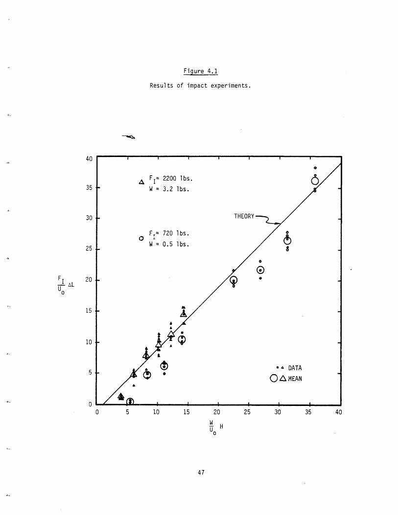
Figure 4.1
Results of impact experiments.
0 5 10 15 20 25
w HU0
30 35 40
47
40
35
30
25
FI 20U AL
Uo
15
10
5
TO
greater than about 7 times the threshold energy. The relatively light 8 oz. hammer
was not as effective as the theory predicted until the supplied energy was greater
than.about 35 times the threshold energy. This was expected since the dynamics of
the situation was ignored in the analysis and becomes important when the weight of
the hammer becomes small compared with the weight of the parts.
48
5.0 CONCLUSIONS AND RECOIiENDATIONS
In many cases, the interference fit has axial symmetry, and so the analysis of
concentric cylinders is a good approximation to the actual geometry involved. Howe-
ver, parts of non cylindrical geometry often occur, such as when pins or bushings are
pressed into housings. The applicability of the cylindrical analysis to these cases
should be explored further.
It has been found that the holding power of an interference fit can be in-
creased if the interference is chosen large enough to cause the stress in the parts
to exceed the elastic limit. Thus it is not uncommon for a fit to be designed so
that the parts yield. If the elastic analysis is used in this case, the calculated
pressure, and so the insertion and withdrawal forces, wil be overestimated. The ana-
lysis of plastic flow in pressurized cylinders must be applied to this situation for
a more accurate description.
The inclusion of the Poisson effect eliminates one of the factors of uncer-
tainty regarding the calculation of insertion and holding forces. Experiments should
be undertaken to see how accurate the theoretical predictions are.
The primary source of error in both the Poisson and the energy analyses is
the assumption that axial stresses are uniform on any circular cross-section of a
cylinder. For the inner member, or shaft, this is a valid assumption. However, if
the outer member has an infinite diameter, for example, the axial stress will vanish
far away from the hole because of shear deformation. This effect is probably of
little consequence since for increasingly large diameters, the forces and energies
predicted in the analyses converge to specific values.
The two impact experiments showed a good correlation between the theory and
data. Flany more experiments must be done to determine how the weight of the impac-
ting hammer affects the insertion produced. Experiments with pneumatic impact ham-
mers should be done to see how accurate the analysis is for this situation, and
whether the effect of preloads is similar to that derived by the quasi static analy-
sis.
49
LIST OF REFERENCES
1. Nevins, J.L., et al., Exploratory Research in Industrial Modular Assembly, C.S.
Draper Laboratory Report No. R-1111, August 1977.
2. Drake, S.H., Using Compliance in Lieu of Sensory Feedback for Automatic
Assembly, Ph.D. Thesis, MIT Mechanical Engineering Department, September, 1977.
3. Shigley, J.E., echanical Engineering Design, cGraw-Hill, 1977, pg. 63.
4. Horger, O.J., "Press-and Shrink-fitted Assembly," Chapter 8, ASME Design
Handbook, pp. 340-354.
5. Mechanical Design and Systems Handbook, McGraw-Hill, pp. 231 through 23-14.
6. Mark's Standard Handbook for Mechanical Engineers, McGraw-Hill, pp. 5-66,67;
8-62 to 8-64.
7. Jordan, R.L. Alan, "Designing Interference Fits," Machine Design, Vol. 46,
No. 26, October 31, 1974, pp. 68-72.
8. Conway, H.D., and Farnham, K.A., "Contact Stresses Between Cylindrical Shafts
and Sleeves," International Journal of Engineering Science, Vol. 5, 1967,
pp. 541-554.
9. Steven, G.P., "The Shrink Fit Problem with Both Components Being Elastic,"
International Journal of Engineering Science, Vol. 13, No. 7-8, 1975, pp.
663-673.
10. Lindeman, Robert A., "Finite Element Computer Program for the Solution of
Nonlinear Axisymmetric Contact Problems with Interference Fits," NWL Technical
Report NWL-TR-3148, 1974.
11. Parsons, B., and Wilson, E.A., "A Method for Determining the Surface Contact
Stresses Resulting from Interference Fits." Trans. ASME, Series B, Journal
of Engineering for Industry, Vol. 90, pp. 208-218, February 1970.
12. Lame and Clapeyron, "Memoire sur l'equilibre interieur des corps solides
homogenes," Memoires presentes par divers savans, Vol. 4, 1833.
13. Rankin, A.W., "Shrink-Fit Stresses and Deformations," ASME Series E, Journal
of Applied Mechanics, Vol. 11, No. 2, pp. A-77 through A-85, June, 1944.
50
14. Wilms, E.V., "Motion of an Elastic Rod with External Coulomb Friction," Trans.
ASME Series B, Journal of Engineering for Industry, Vol. 90, p. 526, 1968.
15. WJilms, E.V., "Damping of a Rectangular Stress Pulse in a Thin Elastic Rod by
External Coulomb Friction," Journal of the Acoustical Society of America, Vol.
45, pg. 1049, 1969.
16. Miller, R.K., "Ar Approximate Method of Analysis of the Transmission of Elas-
tic Waves Through a Frictional Boundary," Trans. ASHE, Series E, Journal of
Applied Mechanics, Vol. 44, No. 4, December, 1977, pp. 652-656.
51