assembly manual - spektrum rc
TRANSCRIPT

Twin Otter ARFAssembly Manual
Specifications
Wingspan 820 in (2080mm)Length 650 in (1651mm)Wing Area 738 sq in (4761 sq dm)Weight 11 12ndash12 14 lb (52ndash60 kg)Radio 7-channel w8ndash10 servosEngine 36 2-stroke Power 25
Table of ContentsContents of Kit and Parts Layout2Included Hardware3Introduction4Important Warranty Information4Recommended Setupndash2-stroke Glow4Recommended SetupndashElectric Power (EP)4Radio Equipment Requirements4Transmitter Requirements4Required Tools and Equipment4Required Adhesives4UltraCote Covering Colors4Field Equipment Required4Other Required Items4Using the Manual5Before Starting Assembly5Product Registration5Work Area Cleanliness5Optional Accessory5Workspace Preparation5Elevator Servo Installation6Aileron Servo Installation9Flap Servo Installation12Nacelle Installation16Motor ESC and Battery Installation17Cowling Propeller and Spinner InstallationndashEP202-Stroke Installation21Cowling Propeller and Spinner Installation27Rudder Hinging28Rudder Servo and Linkage Installation29Nose Gear and Steering Servo Installation32Main Landing Gear Installation35Nose Cone Installation37Receiver Battery and Switch Installation37Final Assembly38Center of Gravity41Control Throws41Flight Preparations42Maintaining Your Model42Safety Dorsquos and Donrsquots for Pilots43Dual Rates43Age Requirements43Daily Flight Checks43Flying Tips44Build and Flying Notes44Warranty Information45Compliance Information for the European Union462010 AMA Safety Code47
2
Contents of Kit and Parts Layout1 HAN461001 Fuselage Assembly with Hatch 12 HAN461012 Left Main Gear2 HAN461002 Cowling 13 HAN461013 Right Main Gear3 HAN461003 Left Nacelle 14 HAN461014 Wing and Tail Tubes4 HAN461004 Right Nacelle 15 HAN461015 Landing Gear Fairings5 HAN461006 Left Stabilizer 16 HAN461020 2 14-inch Black Spinners6 HAN461005 Right Stabilizer 17 HAN461021 Fiberglass Nose Cone7 HAN461007 Rudder Not Illustrated8 HAN461008 Left Wing 1 HAN461016 Electric Mounting Pack9 HAN461009 Right Wing 2 HAN461017 Glow Mounting Pack10 HAN461010 Struts 3 HAN461018 Main Hardware Pack11 HAN461011 Nose Gear Assembly 4 HAN461019 Fuel Tanks
Twin Otter ARF Assembly Manual
Packaged in Kit Fuselage assembly with hatch 1 Fiberglass nose cone 1 Right wing 1 Left wing 1 Right stabilizer with elevator 1 Left stabilizer with elevator 1 Right nacelle 1 Left nacelle 1 Rudder 1 Cowling 2 Right main landing gear with screws 1 Left main landing gear with screws 1 Nose leg assembly with screws 1 Landing gear fairings (left and right) 2 Wing struts (left and right) 2 34 x 19 12 inch aluminum wing tube 1 38 x 11 inch aluminum stabilizer tube 1 Fuel tanks 200cc 2 2 14-inch white nylon spinners 2
Control Horn Bag Small control horns 2 rudder 4 x 12 in Phillips head screws 4 rudder control horns Nylon clevises 9 steel pushrods Snap keepers 9 steel pushrods Silicone keepers 18 clevises 14-20 x 2 in nylon screws 2 wing retention
Pushrod Bag 2-56 x 4-in steel pushrod 7 ailerons and flaps 2-56 x 10-in steel pushrods 2 throttles 2-56 x 7-in steel pushrod 1 nose gear steering
Rudder Cable Bag Rudder cable 82 inch 1 rudder cables Copper crimps 4 Wire cable ends 2 EZ links 2 rudder servo
Main Hardware Bag 8-32 x 1-inch Allen head machine screws 6 main landing gear 4 x 716-inch wood screws 3 nose cone 4-40 x 1-inch Allen head machine screws 2 strut to wing attach 8-32 x 1-inch Allen head machine screws 4 nose gear attach
Glow Engine Mount Bag Small nylon engine mount 4 engine 6-32 x 1-inch Allen head machine screws 8 engine mount 6-32 blind nuts 8 engine mount 6 steel washers 4 engine mount 4-40 x 1-inch Allen head machine screws 8 engine 4-40 nylon lock nuts 8 engine 4 steel washers 16 engine
Electric Power Mount Bag 4-40 1 14-inch Allen head machine screws 8 motor 38-inch diameter x 34-inch nylon standoffs 8 motor
Servo Mounting Bag 10 x 11 x 20mm hardwood blocks 10 aileron and flap servos 8 x 8 x 14mm hardwood blocks 4 elevator servos 12-inch hook and loop straps 2 batteryfuel tank 4-inch adhesive-backed hook and loop tape 3
Hatch Screw Pack 2 x 38-inch woodscrews (silver) 12 servo hatches 2 x 14-inch woodscrews (black) 46 hatches and cowls
Included Hardware
3Twin Otter ARF Assembly Manual
4 Twin Otter ARF Assembly Manual
IntroductionHangar 9rsquos latest introduction the Twin Otter is a scale model of the UV-18 lsquoTwin Otterrsquo the military version of the DeHavilland DHC-6 The trim scheme is based on the three UV-18B planes used by the US Air Force Academy cadet parachuting program which carry a pilot copilot and up to 17 jumpers There are only three owned by the Air Force Although this is a multi-engine model the high-wing design and Clark Y airfoil improve low-speed handling and provide stable flight characteristics making this a great first-time twin for intermediate to advanced pilots The Twin Otter ARF also features an electric power option which adds to the reliability It also features fiberglass cowlings and fairings which make it very durable and easy to repair The aircraft also includes fixed gear and large landing flaps to provide easy and fun landings without the addition of complicated landing gear necessary
Important Warranty InformationPlease read our Warranty and Liability Limitations section on page 45 before assembling this product If you as the purchaser are not prepared to accept the liability associated with the use of this Product you areadvised to return this Product immediately in new and unused condition to the place of purchase
Recommended Setupndash2-Stroke Glow Evolutionreg 36NT with muffler (EVOE0520) (2) Evolution propeller 11x6 (EVO11060) (2) Fuel dot filler (HAN115) (2)
Recommended SetupndashElectric Power E-flitereg Power 25 (EFLM4025A) (2) E-flite 40-Amp Pro Switch-Mode BEC Brushless ESC (EFLA1040) (2) E-flite 3200mAh 3S 111V 30 Li-Po (EFLB32003S30) (2) APC Propeller 12x8E (APC12080E)
Radio Equipment Requirements -7-Channel Receiver
The following items are required when installing the7-Channel AR7000 receiver (SPM6070) in your aircraft
Spektrum A6000 Digital Servo (6) SPMSA6000JR SPORT MC35 Micro Servo (4) JSP20030(Note Two less micro servos required for EP version)9-inch Servo Extension (7) JRPA09736-inch Servo Extension (2) JRPA103Y-Harness (3) JRPA135Receiver Battery 6-volt 2300mAh JRPB5006JR Chargeswitch JRPA004
Ailerons A6000 Servo (2) 9-inch Extension (connected to servos) (2) Y-harness (connected to receiver)
Flaps A6000 Servo (2) 9-inch Extension (connected to receiver) (2)
Elevator MC35 Micro Servo (2) 36-inch Extension (plugged into receiver) (2)
Rudder A6000 Servo Y-harness (connected to receiver and nosewheel steering servo)
Nosewheel Steering A6000 Servo 9-inch Extension (connected to servo)
Throttles MC35 Micro Servo (2) Y-harness (connected to receiver) 9-inch extension (connected to servo) (Also required for ESC connection)
Transmitter RequirementsThe Twin Otter requires a minimum of a 5-channel radio to operate all the functions of your aircraft We suggest the following radio systems available through Horizon Hobby or your local hobby distributor
Spektrum DX7 SPM2710JR X9303 24GHz JRP2915
Required Tools and Equipment Drill motor Pin vise Low-tack tape Needle-nose pliers Ruler Sidecutters File Felt-tipped pen Pencil Coarse grit sandpaper Tapered reamer Hobby knife w 11 blade Dental floss Manila card stock Alcohol Paper towels Scissors Double-sided adhesive tape Mixing sticks Mixing cups Small cable ties T-pins Toothpicks String Pliers Pencil Round file Z-bend pliers Phillips screwdriver 1 2 Rotary tool with cutoff wheel and sanding drum Hex wrench 332 18 764-inch 15mm 25mm Open-end wrench 516-inch 10 12 13mm Drill bit 364 564 332 532 964 1164 1364-inch
Required Adhesives Thin CA (PAAPT08) Medium CA (PAAPT02) 30-minute epoxy (PAAPT39) Threadlock (PAAPT42) Canopy glue (PAAPT56)
UltraCote Covering Colors Golden Yellow (HANU889) White (HANU870) Deep Blue (HANU873)
Field Equipment Required Fuel (15 recommended) Long Reach Glow Plug Wrench (HAN2510) Metered Glow Driver with Ni-Cd amp Charger (HAN7101) 2-Cycle Sport Plug (EVOGP1) Manual Fuel Pump (HAN118)
5Twin Otter ARF Assembly Manual
Workspace Preparation
During the course of building your Twin Otter wesuggest you use a soft base on the buildingsurface Such things as a large piece of bedding foam or a thick bath towel work well to protect the model from damage during assembly A flat area measuring at least 28 x 60 inches is required to work on the model sub-assemblies comfortably The completed and assembled model requires a space of 48 x 96 inches Ensure you have adequate lighting and a place to set aside completed parts
The use of a stand to support the fuselage on the workbench is highly recommended This will hold it secure while in different positions during assembly and prevent damage to items such as the tail that are not designed to support the weight of the model
Midwest Stand-In (MID813)
5
Product RegistrationHorizon Hobby wants to ensure that you get maximum enjoyment from your Hangar 9 products We strongly encourage you to register your product using the online Product Registration tool so we can notify you when there are service bulletins new option parts or accessories or updates available for your product
Please register your product today at httpwwwhangar-9comRegister
Work Area CleanlinessIt is a good practice to maintain a clean work areaboth to prevent damage to your model and to keeptrack of parts and hardware Put away any tools notbeing used and set aside parts of the model that arenot being worked onOf special importance is keeping debris out ofsensitive components such as the radio and engine ormotor Tape over engine intake and exhaust portswhen drilling or cutting the firewall and cowling toprevent causing damage to the internal components
Optional AccessorySetting up servos is a whole lot easier with a JRregMatchMakertrade It lets you accurately center servosevaluate endpoints and cycle servos at varyingspeeds without ever having to switch on a transmitterIt allows the precise digital centering of up to 2 servosat a time to help with setup on the building bench
Using the ManualThis manual is divided into sections to help makeassembly easier to understand and to provide breaksbetween each major section In addition check boxeshave been placed next to each step to keep track ofcompleted sections Steps with a single box (1048576) areperformed once steps with two boxes (10485761048576) indicate the step needs to be repeated such as for left and right wing panel or two servos etc Note that references to direction such as left and right-hand are as viewed in the direction of flightBefore beginning it is a good idea to read through themanual completely to familiarize yourself with theassembly process Remember to take your time andfollow the directions
Before Starting AssemblyBefore beginning the assembly of your model removeeach part from its bag for inspection Closely inspect the fuselage wing panels rudder and stabilizer for damage If you find any damaged or missing parts contact the place of purchase
If you find any wrinkles in the covering use a heat gun or covering iron to remove them Use caution while working around areas where the colors overlap to prevent separating the colors
HAN100 ndash Heat Gun
HAN150 ndash Covering Glove
HAN101 ndash Sealing Iron
HAN141 ndash Sealing Iron Sock
6 Twin Otter ARF Assembly Manual
Elevator Servo InstallationParts Required Stabilizer halves (left and right) Micro servos with hardware (2) Snap keepers (2) Clevises (2) Silicone keepers (2) 4-inch steel pushrods (2) 8 x 8 x 14mm servo mounting blocks (4) 2 x 38-inch woodscrews (8) Radio
Tools Required Ruler 1 Phillips screwdriver Sidecutters Pin vise 116-inch drill bit 564-inch drill bit Pliers Pencil Felt-tipped pen Low-tack tape Thin CA 30-minute epoxy Mixing sticks Mixing cups Z-bend pliers Hobby knife with 11 blade
Note The left-hand elevator servo installation is shown here
1048576 Step 1Prepare two servos by installing rubber mounting grommets and brass bushings Note that the bushings are installed from the bottom of the servo
1048576 Step 2Use a 1 Phillips screwdriver to remove the small arm from the servo Use sidecutters to remove three arms from a standard 4-way servo arm leaving one long arm Center the servo using your radio and install the arm as shown
1048576 Step 3Repeat step 2 to install the arm on the second servo but install the arm in the opposite direction
1048576 1048576 Step 4Enlarge the outer hole in the servo arm using a 564-inch drill bit in a pin vise providing a servo arm length of 12 inch (13mm)
1048576 1048576 Step 5Remove the elevator servo hatch from the lower surface of the stabilizer Place the servo against the inside surface of the hatch and use a ruler to position it 14 inch from the aft end of the hatch
7Twin Otter ARF Assembly Manual
1048576 1048576 Step 6Use a pencil to mark the servo location on the inside of the hatch
1048576 1048576 Step 7Mix a small amount of 30-minute epoxy and glue the8 x 8 x 14mm servo mounting blocks to the hatch
1048576 1048576 Step 8Set the servo in place on the mounting block with a 132-inch gap between the servo and the hatch surface Mark the servo mounting hole locations on the blocks with a pencil
1048576 1048576 Step 9Remove the servo and use a 116-inch drill bit in a pin vise to drill the mounting holes Apply a small drop of thin CA to each of the holes to strengthen the wood Allow the CA to cure without using accelerator
1048576 1048576 Step 10Use a 1 Phillips screwdriver and the hardware provided with the servo to install it on the hatch Be sure to maintain a 132-inch gap between the servo and the hatch surface
1048576 1048576 Step 11Use a hobby knife to trim the CA hinge where it protrudes into the servo bay in the stabilizer Be careful not to puncture the upper skin
8 Twin Otter ARF Assembly Manual
1048576 1048576 Step 12Use a 1 Phillips screwdriver to thread a 2 x 38-inch woodscrew into each of the mounting holes in the stabilizer Remove the screw and apply a small drop of thin CA to each hole to harden the wood and help retain the screw Allow the CA to cure without using accelerator
1048576 1048576 Step 13Feed the elevator servo lead through the forward holes in the ribs to the stabilizer root and set the hatch in place
1048576 1048576 Step 14Use a 1 Phillips screwdriver to secure the hatch to the stabilizer with four 2 x 38-inch woodscrews
1048576 1048576 Step 15Slide a silicone keeper onto a 4-inch steel elevator pushrod then thread on a clevis so it is centered on the threads
1048576 1048576 Step 16Center the elevator by aligning the balance tab to the stabilizer Secure it in place with low-tack tape on both the top and bottom sides
1048576 1048576 Step 17Attach the clevis to the outer hole of the elevator horn Use your radio to center the elevator servo then use a felt-tipped pen to mark the pushrod at the servo arm
9Twin Otter ARF Assembly Manual
1048576 1048576 Step 18Remove the pushrod from the elevator horn and use pliers to make a 90-degree bend in the pushrod at the marked location Trim the bent portion to a length of 14-inch with sidecutters
1048576 1048576 Step 19Attach the clevis to the outer hole of the control horn and secure it with the silicone keeper Slide the bent end through the outer servo arm hole and secure it with a snap keeper
1048576 Step 20Optional Setup You may choose to use Z-bend pliers to form a Z-bend in the pushrod in place of the 90-degree bend and snap keeper
1048576 Step 21Repeat steps 4 through 19 to install the servo in the opposite stabilizer half
Aileron Servo InstallationParts Required Wing panels (left and right) Servos with hardware (2) Clevises (2) Snap keepers (2) Silicone keepers (2) 4-inch steel pushrods (2) 9-inch servo extension leads (2) 2 x 38-inch woodscrews (8) 10 x 11 x 20mm servo mounting blocks (4) Radio
Tools Required Ruler 1 Phillips screwdriver Pin vise 564-inch drill bit Sidecutters Pencil Low-tack tape Felt-tipped pen Dental floss Thin CA 30-minute epoxy Mixing sticks Mixing cups Pliers Z-bend pliers
Note The left-hand aileron installation is shown here
1048576 Step 1Install the grommets and bushings in each of the two aileron servos Note that the bushings are installed from the bottom of the mounting lugs
10 Twin Otter ARF Assembly Manual
1048576 Step 2Locate the large 4-way servo arm Use sidecutters to remove three of the arms leaving one long arm Use your radio to center the servo and install the arm using a 1 Phillips screwdriver
1048576 Step 3Prepare a second servo for the right-hand aileron with the arm facing the opposite direction
1048576 1048576 Step 4Use a 564-inch drill bit in a pin vise to enlarge the outer hole in each servo arm
1048576 1048576 Step 5Remove the hatch from the wing and position the servo against the inside surface so that it is equally spaced in the long direction of the hatch There will be approximately a 316 inch gap at each end
1048576 1048576 Step 6Align the servo arm with the top edge of the hatch and mark the mounting lug locations with a pencil
1048576 1048576 Step 7Mix a small amount of 30-minute epoxy and glue the10 x 11 x 20mm servo mounting blocks in place
11Twin Otter ARF Assembly Manual
1048576 1048576 Step 8Place the servo on the mounting blocks with a 132-inch gap between it and the hatch Use a pencil to mark the servo hole locations on the blocks
1048576 1048576 Step 9Use a 564-inch drill bit in a pin vise to drill the servo mounting holes Apply a small drop of thin CA to each hole to strengthen the wood and help retain the screw Allow the CA to cure without using accelerator
1048576 1048576 Step 10Use a 1 Phillips screwdriver to install the servo with its provided hardware
1048576 1048576 Step 11Attach a 9-inch servo extension lead to the servo and secure the connection with a piece of dental floss
Hint Apply a very small drop of thin CA to the knot to prevent it coming loose
1048576 1048576 Step 12Use a 1 Phillips screwdriver to thread a 2 x 38-inch screw into each of the hatch mounting holes in the wing Remove the screw and apply a small drop of thin CA to each hole to strengthen the wood Allow the CA to cure without using accelerator
1048576 1048576 Step 13There is a pull string provided to draw the aileron servo lead through the wing Tape the string to the servo extension and pull it through to the wing root
12 Twin Otter ARF Assembly Manual
1048576 1048576 Step 16Slide a silicone keeper onto a 4-inch steel pushrod then thread on a clevis so it is centered on the threads
1048576 1048576 Step 17Attach the clevis to the outer hole of the aileron control horn Center the servo then use a felt-tipped pen to mark the pushrod at the servo arm
1048576 1048576 Step 18Remove the pushrod and use pliers to make a 90-degree bend at the mark Trim the bent portion of the pushrod to a length of 14 inch using sidecutters
1048576 1048576 Step 19Attach the clevis to the outer hole of the control horn and secure it with the silicone keeper Slide the bent portion of the pushrod through the outer hole of the servo arm and secure it with a snap keeper
1048576 1048576 Step 14Use a 1 Phillips screwdriver to install the aileron hatch with four 2 x 38-inch woodscrews
1048576 1048576 Step 15Center the aileron by aligning it with the fixed portion of the wing tip and tape it in place with low-tack tape
13Twin Otter ARF Assembly Manual
1048576 1048576 Step 20Use a piece of low-tack tape and a felt-tipped pen to label the aileron lead where it exits the wing root
1048576 1048576 Step 21Optional Setup You may choose to use Z-bend pliers to form a Z-bend in the pushrod in place of the 90-degree bend and snap keeper
1048576 Step 22Repeat steps 4 through 20 to install the servo in the right-hand wing panel
Flap Servo InstallationParts required Wing panels (left and right) Servos with hardware (2) 4-inch steel pushrods (2) Clevises (2) Snap keepers (2) Silicone keepers (2) Radio 10 x 11 x 20mm servo mounting blocks (4) 2 x 38-inch woodscrews (8)
Tools Required Ruler 1 Phillips screwdriver Pin vise 564-inch drill bit Pliers Sidecutters Pencil Thin CA 30-minute epoxy Mixing sticks Mixing cups
Note the left-hand side installation is shown here
1048576 Step 1Prepare two flap servos by installing grommets and bushings Note that the bushings are installed from the bottom of the mounting lugs
1048576 1048576 Step 2Locate the large 4-way servo arm Use sidecutters to remove three arms leaving one long arm Center the servo using your radio then use a 1 Phillips screwdriver to install the arm as shown
1048576 1048576 Step 3Use a 564-inch drill bit in a pin vise to enlarge the second hole from the center providing a servo arm length of 932 inch (7mm)
14 Twin Otter ARF Assembly Manual
1048576 1048576 Step 4Use sidecutters to remove the excess servo arm beyond the enlarged second hole
1048576 1048576 Step 5Remove the flap hatch from the lower wing Note the orientation of the hatch by the black portion of its covering Position the servo as shown with the bottom of the servo 18 inch above the outboard edge of the hatch and centered fore and aft
1048576 1048576 Step 6Use a pencil to mark the servo mounting locations on the hatch
1048576 1048576 Step 7Mix a small amount of 30-minute epoxy and glue the 10 x 11 x 20mm mounting blocks to the hatch Orient the blocks so they do not protrude beyond the edge of the hatch
1048576 1048576 Step 8Place the servo on the mounting blocks with a 132-inch gap between it and the hatch Use a pencil to mark the mounting hole locations
1048576 1048576 Step 9Use a 564-inch drill bit in a pin vise to drill the servo mounting holes Apply a small drop of thin CA to each to strengthen the wood Allow the CA to cure without using accelerator
15Twin Otter ARF Assembly Manual
1048576 1048576 Step 10Use a 1 Phillips screwdriver and the hardware provided with the servo to install it on the hatch
1048576 1048576 Step 11Use a 1 Phillips screwdriver to thread a 2 x 38-inch woodscrew into each of the hatch mounting holes in the wing Remove the screw then apply a drop of thin CA in each hole to strengthen the wood
1048576 1048576 Step 12Slide a silicone keeper onto a 4-inch steel pushrod then thread on a clevis so it is centered on the threads Measure 2 inches from the clevis pin and use pliers to make a 90-degree bend at that location Trim the bent portion of the pushrod to a length of 14 inch
1048576 1048576 Step 13Deflect the flap and insert the pushrod through the hole in the wing trailing edge with the bend towards the wing root (left-hand side) Attach the clevis to the flap horn and secure it with the silicone keeper
1048576 1048576 Step 14Feed the servo lead to the wing root Insert the bent end of the pushrod into the servo arm and secure it with a snap keeper
1048576 1048576 Step 15Use a 1 Phillips screwdriver to install the hatch on the wing with four 2 x 38-inch woodscrews
16 Twin Otter ARF Assembly Manual
1048576 Step 16Perform steps 2 through 15 to install the right-hand flap servo Note that the servo position on the hatch is different for the right-hand side When performing step 5 position the servo 14 inch from the edge of the hatch rather than 18 inch as for the left-hand side
Note The pushrod length provided will place the flaps in the mid-position with the servo centered This will ensure correct operation throughout the range of motion
Nacelle InstallationParts Required Wing panels (left and right) Nacelles (left and right)
Tools Required Low-tack tape 30-minute epoxy Mixing sticks Mixing cups Paper towels Felt-tipped pen Canopy glue 2 34-inch wooden dowel
1048576 Step 1Identify the left and right-hand nacelles The larger hole on the lower surface of the nacelle locates to the inboard side to receive the wing strut Label each nacelle and wing panel with low-tack tape to prevent installing them incorrectly
1048576 1048576 Step 2Remove the hatch and cowl from the nacelle Trial fit the nacelle and check that it will seat fully against the wing If there is resistance to the nacelle fitting properly check that there is not a buildup of fiberglass between each of the nacelle sides and the motor box Use a flat file to remove the excess if necessary
1048576 1048576 Step 3Mix some 30-minute epoxy and apply it to each of the plywood ribs on the wing
17Twin Otter ARF Assembly Manual
1048576 1048576 Step 4Slide the nacelle into place and push it all the way against the wing Use low-tack tape if necessary to hold the nacelle in place while the glue curesHint Cut a 2 34 inch piece of dowel and insert it between the motor box sides to help the nacelle make complete contact with the wing ribs
1048576 1048576 Step 5Apply a bead of canopy glue around the perimeter of the nacelle where it meets the wing surface Use tape or weights as necessary to hold the nacelle in contact with the wing Use a damp paper towel to clean any excess glue before it cures
1048576 Step 6Repeat steps 1 through 5 to install the opposite nacelle
Motor ESC and Battery InstallationParts Required Wing panels (left and right) Motors (2) ESC (2) 19mm standoffs Firewall drilling template 4 steel washers (8) 4-40 blind nuts (8) Batteries (2) Hook and loop strap (2) 9-inch servo extensions (2) 4-40 x 1 14-inch Allen head machine screws (8) Double-sided adhesive tape (not included) Cable ties (not included)
Tools Required Felt-tipped pen 1 Phillips screwdriver Drill motor Low-tack tape Pin vise Ruler 116-inch drill bit 964-inch drill bit 332-inch hex wrench Scissors Dental floss Threadlock Tapered reamer
1048576 1048576 Step 1Apply a drop of threadlock to each of the screws provided with the motor then use a 1 Phillips screwdriver to install the mount
1048576 1048576 Step 2Position the firewall drilling template against the firewall and flush with its edges Use low-tack tape to hold it in place while marking the electric motor mounting holes with a felt-tipped pen
1048576 1048576 Step 3Remove the template and use a 116-inch drill bit in a pin vise to pilot drill the holes
18 Twin Otter ARF Assembly Manual
1048576 1048576 Step 4Use a drill motor and 964-inch drill bit to enlarge the four mounting holes
1048576 1048576 Step 5From inside the nacelle insert a 4-40 blind into each of the mounting holes Use a 4-40 screw 4 washer and 19mm standoff to draw each of the blind nuts into place with a 332-inch hex wrench
1048576 1048576 Step 6Measure 58 inch from the right-hand side of the firewall and mid-way between the upper and lower mount holes Make a mark with a felt-tipped pen
1048576 1048576 Step 7Use a tapered reamer to make a 12-inch hole through the firewall at the marked location
1048576 1048576 Step 8Cut a hook and loop strap to a length of 8 inches using scissors Slide it through the aft set of slots in the nacelle floor
1048576 1048576 Step 9Connect a 9-inch servo extension lead to the ESC and secure it with dental floss
Hint Apply a very small drop of thin CA to the knot to prevent it coming loose
19Twin Otter ARF Assembly Manual
1048576 1048576 Step 10Feed the extension lead through the wing to the wing root and pass the motor leads through the firewall Use double-sided adhesive tape to attach the ESC to the right-hand side of the battery compartment
1048576 1048576 Step 11Place a 4 steel washer on each of the 4-40 x 1 14-inch Allen head machine screws Apply a drop of threadlock to each of the screws then use a 332-inch hex wrench to install the motor and 19mm standoffs Mount the motor with the leads to the right-hand side
1048576 1048576 Step 12Connect the motor leads to the ESC
1048576 1048576 Step 13Use cable ties to secure the leads so they cannot interfere with operation of the motor
1048576 1048576 Step 14Insert the battery and secure it with the hook and loop strap You may choose to use adhesive-backed hook and loop tape (not included) under the battery for additional security
1048576 1048576 Step 15Repeat steps 1 through 14 for the opposite side
Hint Glue a scrap block of balsa to the back of the firewall to prevent the battery contacting the motor mount screws
20 Twin Otter ARF Assembly Manual
Cowling Propeller and Spinner InstallationndashEP
Parts Required Wing panels (left and right) 2 x 14-inch woodscrews (8) Cowlings (2) 2 14-inch spinners (2) Propellers (2) Propeller adapters (2)
Tools Required Ruler 1 Phillips screwdriver Pin vise Felt-tipped pen 116-inch drill bit 564-inch drill bit Tapered reamer Low-tack tape
1048576 1048576 Step 1Apply a 2 12-inch long piece of low-tack tape to the aft edge of the cowling on both sides Align it flush to the aft edge and just above the blue trim line
1048576 1048576 Step 2Use a felt-tipped pen to mark a line on the tape 14 inch forward of the aft edge
1048576 1048576 Step 3Measure 58 and 2 14 inches above the top of the blue trim line and make two marks with a felt-tipped pen
1048576 1048576 Step 4Use a 116-inch drill bit in a pin vise to drill a hole at each of the marked locations Remove the tape
1048576 1048576 Step 5Place the cowling on the nacelle and use the trim stripes as an alignment guide Secure the cowling to the nacelle with low-tack tape
21Twin Otter ARF Assembly Manual
1048576 1048576 Step 6Use the holes in the cowling to drill mounting holes in the nacelle using a pin vise and 116-inch drill bit Remove the cowling and apply a small drop of thin CA to each of the mounting holes in the nacelle Allow the CA to cure without using accelerator
1048576 1048576 Step 7Use a 564-inch drill bit in a pin vise to enlarge the mounting holes in the cowling
1048576 1048576 Step 8Use a 1 Phillips screwdriver to install the cowling with four 2 x 14-inch woodscrews
1048576 1048576 Step 9Slide the prop adapter onto the motor shaft then install the spinner backplate and propeller Use the shaft of a hex wrench to tighten the propeller nut Secure the spinner cone using a 1 Phillips screwdriver and the screws provided with the spinner
2-Stroke InstallationParts Required Wing panels (left and right) Micro servos with hardware (2) 9-inch servo extension leads (2) Engines (2) Radio Throttle pushrods (2) Clevises (2) Silicone keepers (2) Engine Mounts (2 sets) Fuel tanks (2) Hook and loop strap (2) Cowlings (2) Firewall drilling template 4 steel washers (16) 8 steel washers (8) 6-32 blind nuts (8) 4-40 nylon lock nuts (8) 4-40 x 1-inch Allen head machine screws (8) 6-32 x 1-inch Allen head machine screws (8)
Tools Required Ruler Pencil Felt-tipped pen 1 Phillips screwdriver Pliers Drill motor Tapered reamer Thin CA 332-inch hex wrench 764-inch hex wrench Round file Low-tack tape Dental floss Threadlock Sidecutters Needle-nose pliers 14-inch wrench Drill bits 116 1164 516-inch Rotary tool with cutoff wheel and drum sander
22 Twin Otter ARF Assembly Manual
1048576 1048576 Step 1Position the firewall drilling template against the firewall and flush with its edges Tape it in place with low-tack tape then use a felt-tipped pen to mark the 2-stroke engine mounting holes
1048576 1048576 Step 2Remove the template and use a 116-inch drill bit in a pin vise to pilot drill the mounting holes Note When drilling the upper hole use care not to drill too far beyond the firewall and into the fiberglass of the nacelle
1048576 1048576 Step 3Use an 1164-inch drill bit in a drill motor to enlarge the mounting holes
1048576 1048576 Step 4Use a cutoff wheel in a rotary tool to shorten one of the 6-32 Allen head machine screws to a length of 34 inches Also modify one 6-32 blind nut by removing one side of the flange as shown
1048576 1048576 Step 5Press the blind nuts into the mounting holes from inside the nacelle The modified blind nut is installed in the left mounting hole against the side of the motor box Use the 6-32 x 34-inch screw with a 6 washer and engine mount to draw the blind nuts into place with a 764-inch hex wrench
1048576 1048576 Step 6Measure 1316 inch (20mm) across from the lower left-hand engine mount hole and drill a 18-inch hole for the throttle pushrod
23Twin Otter ARF Assembly Manual
1048576 1048576 Step 7Use a ruler to measure the vertical centerline of the firewall and mark it with a felt-tipped pen Measure down 1 932 inch from the top of the firewall and mark a horizontal line
1048576 1048576 Step 8Use a drill motor and 516-inch drill bit to drill a hole 532 inch each side of the centerline
1048576 1048576 Step 9Use a round file to remove the material between the holes creating a slot measuring 516 x 58 inches
1048576 1048576 Step 10Place a 6 steel washer onto each of the 6-32 Allen head machine screws Insert the screws and washers in the engine mounts noting that the modified screw locates in the lower of the two holes under the beveled edge of the right-hand mount
1048576 1048576 Step 11Apply a drop of threadlock to each of the screws then use a 764-inch hex wrench to secure the mounts to the firewall
1048576 1048576 Step 12Perform steps 1 through 7 beginning on page 20 to install the cowling on the nacelle Set the front face of the cowl 3 716 inches from the firewall when taping it in place to drill the mounting holes in the nacelle
24 Twin Otter ARF Assembly Manual
1048576 1048576 Step 13Invert the nacelle and position the engine on the mounts so the face of the drive washer is 3 12 inches from the firewall
1048576 1048576 Step 14Mark the engine mounting holes on the mounts then remove the engine Use a drill motor and 18-inch bit to drill the mounting holes
1048576 1048576 Step 15Place a 4 steel washer onto each of the 4-40 x 1-inch Allen head machine screws Place the engine on the mount and insert the screws Slide a second 4 washer on each screw then thread on a 4-40 nylon locknut Use a 332-inch hex and 14-inch wrench to tighten the engine to the mount
1048576 1048576 Step 16Prepare a micro servo with grommets and bushings Note that the bushings are installed from the bottom of the servo
1048576 1048576 Step 17Attach a 9-inch servo extension lead to the servo and secure the connectors with dental flossHint Apply a very small drop of thin CA to the knot to prevent it coming loose
1048576 1048576 Step 18Use a 1 Phillips screwdriver to remove the small arm Use sidecutters to remove three arms from a standard 4-way arm leaving one long arm Install the arm on the servo as shown
25Twin Otter ARF Assembly Manual
1048576 1048576 Step 19Use a 564-inch bit in a pin vise to enlarge the outer hole of the servo arm then install an EZ link Use needle nose pliers to press the keeper into place
1048576 1048576 Step 20Set the servo in place in the nacelle and mark the mounting hole locations with a pencil
1048576 1048576 Step 21Remove the servo and use a 116-inch drill bit in a pin vise to drill the mounting holes Apply a drop of thin CA to each of the holes to strengthen the wood Allow the CA to cure without using accelerator
1048576 1048576 Step 22Feed the throttle servo lead through the hole in the spar and through the wing to the wing root Position the servo with the output shaft to the left-hand side Use the hardware provided with the servo to install it with a 1 Phillips screwdriver
1048576 1048576 Step 23Insert an 11 34-inch hook and loop strap through the forward slots in the nacelle tray
1048576 1048576 Step 24Guide the fuel lines through the slot in the firewall and use the hook and loop strap to secure the fuel tank in place Note that the tank stopper and vent tube should be towards the top
26 Twin Otter ARF Assembly Manual
1048576 1048576 Step 25Use sidecutters to trim the threaded portion of the throttle pushrod to a length of 38 inch Then use pliers to bend the pushrod to the dimensions shown
1048576 1048576 Step 26Slide a silicone keeper onto the pushrod then thread on a nylon clevis up to the bend
1048576 1048576 Step 27Slide the pushrod through the hole in the firewall and into the EZ link on the servo Attach the nylon clevis to the outer hole of the carburetor throttle arm and secure it with the silicone keeper
1048576 1048576 Step 28Now is a good time to set the throttle travel before thecowl is installed Use your radio to move the throttleservo to the fully open position Move the pushrodforward to open the carburetor to the full open positionand use a 1 Phillips screwdriver to secure the throttlepushrod in the EZ link Now use your radio to checkoperation of the throttle throughout its range and makeany adjustments to the pushrod or servo travel volumeas necessary Using the equipment and dimensionsshown here we found ATV values of 100 for bothhigh and low settings to be ideal
1048576 1048576 Step 29Use these pictures as a guide to cut the firewall and lower nacelle for the muffler A cutoff wheel and sanding drum in a rotary tool work well for this Install the muffler using the gasket and hardware provided with the engine
27Twin Otter ARF Assembly Manual
1048576 1048576 Step 30Connect the fuel tank vent line (pink) to the pressure nipple on the muffler and the feed line (green) to the fuel inlet on the carburetor or needle valve assembly
1048576 1048576 Step 31Shown here is a tee fitting installed in the feed line You may choose to install a fuel filler dot in the cowling or run a fuel into the tank compartment for fueling purposes
1048576 Step 32Repeat steps 1 through 31 for the opposite side
Cowling Propeller and Spinner Installationndash2-Stroke
Parts Required Wing Panels (left and right) Cowlings (2) Clear cowlings (2) Propellers (2) Spinners (2) 2 x 14-inch woodscrews (8)
Tools Required Ruler Felt-tipped pen 1 Phillips screwdriver Rotary tool with cutoff wheel and drum sander
1048576 1048576 Step 1Use scissors to trim the clear cowling so it will fit over the fiberglass cowl Transfer the mounting holes to the clear cowl to serve as a reference
1048576 1048576 Step 2Cut openings in the clear cowling so that it can be mounted without obstruction from the engine You may find it easier to remove the needle valve until after the cowl is fit
1048576 1048576 Step 3Slide the clear cowling over the fiberglass cowl and mark the required cutouts with a felt-tipped pen Then use a cutoff wheel and drum sander in a rotary tool to make the cutouts in the fiberglass cowling
28 Twin Otter ARF Assembly Manual
1048576 1048576 Step 6Install the spinner backplate and propeller and secure them with the propeller washer and nut Use a 1 Phillips screwdriver to secure the spinner cone with the provided 4 x 716-inch screws
1048576 1048576 Step 4Shown here is the cutout for the muffler Use the nacelle cutout made in step 29 as a guide for the muffler opening in the cowling
1048576 1048576 Step 5Use a 1 Phillips screwdriver to install the cowling with four 2 x 14-inch woodscrews
Rudder HingingParts Required Fuselage Rudder CA hinges (4)
Tools Required T-pins Thin CA
1048576 Step 1Prepare four CA hinges by inserting a T-pin in the center of each hinge
29Twin Otter ARF Assembly Manual
1048576 Step 2Slide a CA hinge into each of the pre-cut hinge slots in the rudder leading edge
1048576 Step 3Slide the rudder hinges into the slots in the fin and align the rudder with the top and bottom of the fin
1048576 1048576 Step 4Remove the T-pins and apply 3ndash4 drops of thin CA to each of the hinges Allow the CA to cure without using accelerator so it can penetrate the hinges completely
Rudder Servo and Linkage Installation
Parts Required Fuselage Servo with hardware 7-inch steel pushrod Small control horns (2) Copper sleeves (4) 82-inch rudder cable Wire cable ends (2) EZ links (2) Radio M3 x 4 screws (2)
Tools Required Felt-tipped pen Pin vise 116-inch drill bit 564-inch drill bit Needle-nose pliers 1 Phillips screwdriver Sidecutters Pencil Thin CA Ruler Threadlock Hobby knife with 11 blade
1048576 Step 1Prepare the rudder servo by installing the grommets and bushings Note that the bushings are installed from the bottom of the servo
30 Twin Otter ARF Assembly Manual
1048576 Step 2Use sidecutter to trim two arms from a large 4-way servo arm leaving two arms opposite each other Center the servo using your radio then use a 1 Phillips screwdriver to install the arm as shown
1048576 Step 3Use a 564-inch drill bit in a pin vise to enlarge the outer holes in the servo arm This provides a servo arm length of 58 inches (16mm) from center Install an EZ link in each of the holes
1048576 Step 4Place the servo in the radio tray in the upper fuselage and mark the mounting hole locations with a pencil
1048576 Step 5Remove the servo and use a 116-inch drill bit in a pin vise to drill the mounting holes Apply a drop of thin CA to each of the holes to strengthen the wood Allow the CA to cure without using accelerator
1048576 Step 6Use a 1 Phillips screwdriver and the hardware provided with the servo to secure it to the radio tray with the output shaft forward
1048576 1048576 Step 7Insert the 7-inch steel pushrod into the rudder cable slot in the right-hand side of the rear fuselage Use a felt-tipped marker to mark the rudder
31Twin Otter ARF Assembly Manual
1048576 1048576 Step 8Remove the pushrod Place a small control horn on the rudder at the marked location and use a felt-tipped pen to mark the mounting holes
1048576 1048576 Step 9Use a 116-inch drill bit in a pin vise to drill the mounting holes for the control horn Apply a drop of thin CA to strengthen the wood and help retain thescrews Allow the CA to cure without using accelerator
1048576 1048576 Step 10Use a 1 Phillips screwdriver to install the control horn with two 2 x 12-inch screws
1048576 Step 11Repeat steps 7 through 10 to install the second control horn on the left-hand side of the rudder You may need to use a hobby knife to remove the covering from the cable exit hole in the fuselage
1048576 Step 12Remove the hatch from the right-hand side of the rear fuselage and set it aside Fold the 82-inch rudder cable in half and use sidecutters to cut it into two 41 inch lengths Insert each cable into the guide tubes in the rear fuselage and feed them into the forward fuselage area Tape the cable ends to the fuselage so they donrsquot get pulled inside the fuselage
1048576 Step 13Open the cabin doors in the left-hand side of the fuselage and bring the cables out to prepare the end connections Slide a copper sleeve onto each of the cables then insert the cable ends through the loop of a wire cable end and back through the sleeve
32 Twin Otter ARF Assembly Manual
1048576 Step 14Use pliers to crimp the sleeves and secure them to the cable ends
1048576 Step 15Insert the cable ends into the EZ links on the servo so that 14 inch of the wire protrudes Be sure the cables are not crossed inside the fuselage Apply a small drop of threadlock to each of the M3 x 4mm screws Use a 1 Phillips screwdriver to install the screws in the EZ links and secure the cable ends to the servo
1048576 Step 16Slide a copper sleeve onto each of the cables then pass them through the second hole from the base of the rudder control horns Insert the ends of the cables back through the sleeves
1048576 Step 17Use you radio to check that the rudder servo is centered and center the rudder by aligning the balance tab at the top with fin Then use pliers to crimp the sleeves to the cables Trim the excess cable with sidecutters Any required cable tension adjustments can be made at the servo end
Nose Gear and Steering Servo Installation
Parts Required Fuselage Nose gear assembly 7-inch steel pushrod Nylon clevis Silicone keeper Servo with hardware 8-32 x 1-inch Allen head machine screws (4) 2 x 14-inch woodscrews (4)
Tools Required Ruler Pliers Felt-tipped pen Pencil Pin vise 1 Phillips screwdriver 116-inch drill bit 564-inch drill bit Sidecutters 18-inch hex wrench Thin CA Threadlock Dental floss
1048576 Step 1Invert the fuselage on the work surface Remove the hatch from the forward fuselage and set it aside
33Twin Otter ARF Assembly Manual
1048576 Step 2Prepare the nosewheel steering servo with grommets and bushings Note that the bushings are installed from the bottom of the servo
1048576 Step 3Use sidecutters to remove three arms from a standard 4-way servo arm leaving one long arm The required servo arm length is 12 inch (13mm) Center the servo using your radio then use a 1 Phillips screwdriver to install the arm as shown
1048576 Step 4Set the servo in place and mark the mounting holes with a pencil
1048576 Step 5Remove the servo and drill the mounting holes with a 116-inch drill bit in a pin vise Apply a drop of thin CA to each of the holes to strengthen the wood Allow the CA to cure without using accelerator
Hint Place a rag in the fuselage so that any drip of CA does not damage the windshield
1048576 Step 6Use a 1 Phillips screwdriver and the hardware provided with the servo to install it with the output shaft towards the rear of the fuselage
1048576 Step 7Slide a silicone keeper onto the pushrod then thread on a nylon clevis so that it is centered on the threads Measure 4 12 inches from the clevis pin and make a mark with a felt-tipped pen Use pliers to form a 90-degree bend at the marked location
34 Twin Otter ARF Assembly Manual
1048576 Step 8Use sidecutters to trim the bent portion of the wire to a length of 38 inch (9mm)
1048576 Step 9From inside the fuselage pass the bent end of the pushrod through the slot in the bulkhead then connect the clevis to the outer hole of the servo arm and secure it with the silicone keeper
1048576 Step 10Use a 564-inch drill bit in a pin vise to enlarge the center hole in the nose gear steering arm
1048576 Step 11Prepare the four 8-32 x 1-inch nose gear mounting screws by applying a drop of threadlock to the ends of the threads
1048576 Step 12Insert the steering pushrod into the center hole of the steering arm while placing the nose gear against the bulkhead Note that the anti-torque (scissor) link faces forward
1048576 Step 13Use a 18-inch hex wrench to secure the nose gear to the bulkhead with four 8-32 x 1-inch Allen head screws
35Twin Otter ARF Assembly Manual
1048576 Step 14Set the hatch in place and mark the mounting hole locations with a pencil
1048576 Step 15Remove the hatch and use a 116-inch drill bit in a pin vise to drill the mounting holes Apply a drop of thin CA to each of the holes to strengthen the wood Allow the CA to cure without using accelerator
1048576 Step 16Use a 1 Phillips screwdriver to install the hatch with four 2 x 14-inch woodscrews
Main Landing Gear InstallationParts Required Fuselage Wing tube Wing struts (left and right) Landing gear (left and right) Wing panels (left and right) Landing gear fairings (left and right) 8-32 x 1-inch Allen head machine screws (6)
Tools Required Low-tack tape 18-inch hex wrench Threadlock Canopy glue
Step 11048576 1048576 Slide the fairing onto the landing gear
36 Twin Otter ARF Assembly Manual
1048576 1048576 Step 2Prepare two 8-32 x 1-inch screws by applying a drop of threadlock to the end of the threads
1048576 1048576 Step 3Slide the landing gear and fairing into the fuselage Insert an 8-32 x 1-inch screw into the inboard and aft holes and use a 18-inch hex wrench to secure the gear to the fuselage
1048576 1048576 Step 4Insert the wing strut into the gear fairing and align thehole in the strut with the forward landing gear mounting hole Use a 18-inch hex wrench to secure the strut to the fuselage with an 8-32 x 1-inch Allen screw
1048576 1048576 Step 5Insert the wing tube in the fuselage Slide the wing panel onto the tube while guiding the end of the strut into the hole in the lower nacelle Slide the wing panel all the way against the fuselage and engage the strut end in its pocket under the outboard side of the nacelle This sets the strut in the correct location so the gear fairing can be glued in place
1048576 1048576 Step 6Apply a bead of canopy glue around the perimeter of the gear fairing and use low-tack tape to hold it in place against the fuselage while the glue cures Allow the glue to cure completely before removing the tape
1048576 1048576 Step 7Remove the wing panel then repeat steps 1 through 6 to install the opposite landing gear and fairing You may choose to leave the struts installed unless required to remove them for transportation
37Twin Otter ARF Assembly Manual
Nose Cone InstallationParts Required Fuselage Nose cone 4 x 716-inch woodscrews (3)
Tools Required 1 Phillips screwdriver Ruler
1048576 Step 1Use a 1 Phillips screwdriver to install a 4 x 716-inch woodscrew in each of the two holes in the top of the nose bulkhead Install them so that the head of the screw is 18 inch from the face of the bulkhead
1048576 Step 2Slide the nose cone into place over the screws then turn it counterclockwise to engage the screw heads in the keyhole slots in the nose cone bulkhead
1048576 Step 3Use a 1 Phillips screwdriver to install a 4 x 716-inch woodscrew in the lower left side of the cowling to retain it on the fuselage
Receiver Battery and Switch Installation
Parts Required Fuselage Receiver Battery Switch Y-harness (3) 9-inch extensions leads (2) 36-inch extension leads (2)
Tools Required Pin vise Double-sided foam tape 116-inch drill bit 1 Phillips screwdriver
1048576 Step 1Mount the switch in your preferred location It is shown here on the lower fuselage ahead of the main landing gear
38 Twin Otter ARF Assembly Manual
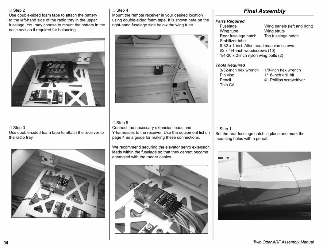
1048576 Step 2Use double-sided foam tape to attach the battery to the left-hand side of the radio tray in the upper fuselage You may choose to mount the battery in the nose section if required for balancing
1048576 Step 3Use double-sided foam tape to attach the receiver to the radio tray
1048576 Step 4Mount the remote receiver in your desired location using double-sided foam tape It is shown here on the right-hand fuselage side below the wing tube
1048576 Step 5Connect the necessary extension leads and Y-harnesses to the receiver Use the equipment list on page 4 as a guide for making these connections
We recommend securing the elevator servo extension leads within the fuselage so that they cannot become entangled with the rudder cables
Final AssemblyParts Required Fuselage Wing panels (left and right) Wing tube Wing struts Rear fuselage hatch Top fuselage hatch Stabilizer tube 8-32 x 1-inch Allen head machine screws 2 x 14-inch woodscrews (10) 14-20 x 2-inch nylon wing bolts (2)
Tools Required 332-inch hex wrench 18-inch hex wrench Pin vise 116-inch drill bit Pencil 1 Phillips screwdriver Thin CA
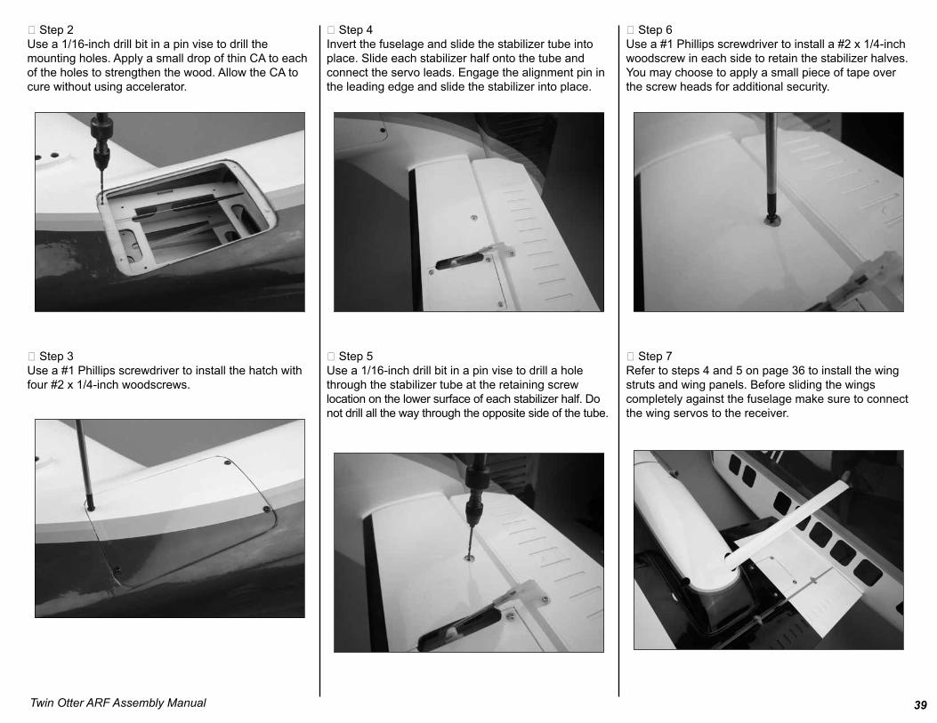
1048576 Step 1Set the rear fuselage hatch in place and mark the mounting holes with a pencil
39Twin Otter ARF Assembly Manual
1048576 Step 2Use a 116-inch drill bit in a pin vise to drill the mounting holes Apply a small drop of thin CA to each of the holes to strengthen the wood Allow the CA to cure without using accelerator
1048576 Step 3Use a 1 Phillips screwdriver to install the hatch with four 2 x 14-inch woodscrews
1048576 Step 4Invert the fuselage and slide the stabilizer tube into place Slide each stabilizer half onto the tube and connect the servo leads Engage the alignment pin in the leading edge and slide the stabilizer into place
1048576 Step 5Use a 116-inch drill bit in a pin vise to drill a hole through the stabilizer tube at the retaining screw location on the lower surface of each stabilizer half Do not drill all the way through the opposite side of the tube
1048576 Step 6Use a 1 Phillips screwdriver to install a 2 x 14-inch woodscrew in each side to retain the stabilizer halves You may choose to apply a small piece of tape over the screw heads for additional security
1048576 Step 7Refer to steps 4 and 5 on page 36 to install the wing struts and wing panels Before sliding the wings completely against the fuselage make sure to connect the wing servos to the receiver
40 Twin Otter ARF Assembly Manual
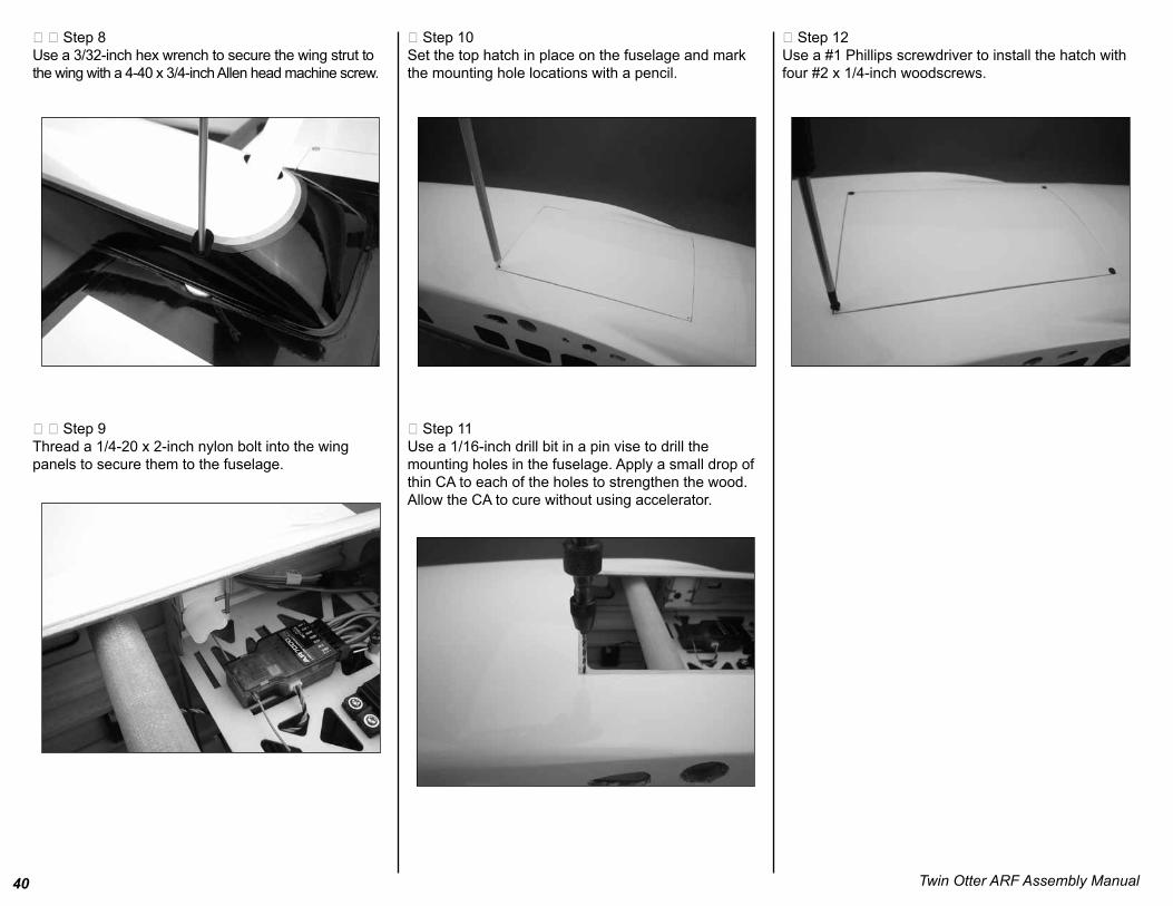
1048576 1048576 Step 8Use a 332-inch hex wrench to secure the wing strut to the wing with a 4-40 x 34-inch Allen head machine screw
1048576 1048576 Step 9Thread a 14-20 x 2-inch nylon bolt into the wing panels to secure them to the fuselage
1048576 Step 10Set the top hatch in place on the fuselage and mark the mounting hole locations with a pencil
1048576 Step 11Use a 116-inch drill bit in a pin vise to drill the mounting holes in the fuselage Apply a small drop of thin CA to each of the holes to strengthen the wood Allow the CA to cure without using accelerator
1048576 Step 12Use a 1 Phillips screwdriver to install the hatch with four 2 x 14-inch woodscrews
41Twin Otter ARF Assembly Manual
Center of GravityAn important part of preparing the aircraft for flightis properly balancing the model
Caution Do not inadvertently skip this step
The recommended Center of Gravity (CG) location foryour model is 2 12 (64mm) to 3 inches (76mm) behind the leading edge of the wing
Mark the location for the Center of Gravity on a piece of low-tack tape on the top of the wing next to the fuselage as shown When balancing your model support the model inverted at the marks made on the top of the wing with your fingers or a commercially available balancing stand This is the correct balance point for your model You may find you need to add a small amount of weight to either the front or back of the fuselage to achieve the correct balance
Control Throws1048576 Step 1Turn on the transmitter and receiver of your modelCheck the movement of the rudder using thetransmitter When the stick is moved right the ruddershould also move right Reverse the direction of theservo at the transmitter if necessary
1048576 Step 2Check the movement of the elevator with the radiosystem Moving the elevator stick toward the bottomof the transmitter will make the elevator move up
1048576 Step 3Check the movement of the ailerons with the radiosystem Moving the aileron stick right will make theright aileron move up and the left aileron move down
1048576 Step 4Use a ruler to adjust the throws of the elevator ailerons flaps and rudder
AileronUp 38 inch (10mm)Down 38 inch (10mm)
ElevatorUp 12 inch (13mm)Down 12 inch (13mm)
RudderLeft 2 inches (51mm)Right 2 inches (51mm)
FlapsMid-position 12 inch (13mm)Full down 1 12 inch (38mm)
Elevator Compensation with FlapMid-position 532 inch (4mm)Full down 38 inch (10mm)
Note Measurements are taken at the inner or widest point on the control surface
These are general guidelines measured from our ownflight tests You can experiment with higher rates tomatch your preferred style of flying
Note Travel Adjust Sub-trim and Dual Rates are not listed and should be adjusted according to each individual model and preference
42 Twin Otter ARF Assembly Manual
Flight PreparationsFlight preparations should be performed each timeyou travel to the flying field Because your model willencounter a variety of situations it is best to keep aneye on the various components of your model to keepit in the best flying condition
1048576 Checking the FrequencyWhen using a Spektrum radio system follow theguidelines for use of DSM radio systems at yourparticular field
1048576 Checking the ControlsBefore starting your engine check to make sure thecontrols are operating in the correct directions and thelinkages and surfaces are not binding anywhere Alsolook at the clevises and clevis retainers to make surethey are secure and will not come loose or fail in flight
1048576 Fueling Your ModelFill the fuel tank with the proper fuel Fill the tank byconnecting the fuel pump to the line going to the needle valve or to the fuel dot on the side of the cowl Disconnect the fuel line attached to the pressure fitting of the muffler your tank is full when fuel begins to run out of the pressure or vent line Reconnect the fuel lines to the needle valve assembly or insert the plug into the fuel dot and connect the line to the muffler
Note It is very important to reconnect the lines tothe correct place If they are reconnectedincorrectly the engine will not run properly
Maintaining Your ModelThe following is a check list you should followevery time you have completed a flying session withyour model Doing so will keep your aircraft in the bestflying condition
1048576 Clean UpAfter a long flying session with your model you will want to clean it before loading it into your vehicle to head home Use a cleaner and a paper towel to wipe down the exterior of your plane removing the fuel residue Remember a clean airplane will last longer since the fuel wonrsquot be able to soak into any exposed wood
1048576 Checking the PropellerCheck to make sure the propeller is tightly secured tothe engine If not remove the spinner and use awrench to tighten it If you have had any not so greatlandings you will want to inspect the propeller for anydamage Small nicks and scratches can quicklybecome fractures causing the propeller to be unsafefor flight Always carry a few spare propellers so adamaged propeller can be replaced at the fieldincreasing your flying time per trip to the field
1048576 Checking the ClevisesInspect the aileron elevator and rudder clevises tomake sure they are connected and in good workingorder If you find a clevis that is showing signs of wearor is broken replace it with a new clevis Also checkthe nylon connectors at the servo for any wear ordamage If they look worn or in bad shape replacethem as well
1048576 Checking the Control HornsInspect the control horns to make sure they have notcrushed the wood of the control surface If so removethe control horn screws to remove the control hornPlace 2ndash3 drops of thin CA into each of the screwholes In addition use a T-pin to poke small holes inthe covering in the area where the control hornmounts then saturate the area with thin CA This willharden the wood and give the control horns a solidsurface to be mounted to
1048576 Checking the Wheel CollarsCheck the setscrews on the wheel collars for the mainand tail wheel to make sure they are not loose Use ahex wrench to tighten the setscrews It is suggested ifthey loosen frequently to remove them reapplythreadlock to the setscrews then secure the wheelcollars back into position
1048576 Check the Muffler BoltsUse the appropriate hex wrench to make sure thehardware holding the muffler onto the engine is tightand has not vibrated loose during flight
1048576 Check the Engine Mount BoltsRemove the spinner (if used) and propeller from theengine Remove the cowling and if necessaryremove the muffler to gain access to the enginemounting bolts Use a Phillips screwdriver or hexwrench to make sure the four bolts securing theengine to the mount or firewall are tight
43Twin Otter ARF Assembly Manual
Safety Dorsquos and Donrsquots for Pilots Ensure that your batteries have been properlycharged prior to your initial flight
Keep track of the time the system is turned on soyou will know how long you can safely operate yoursystem
Perform a ground range check prior to the initialflight of the day See the ldquoDaily Flight ChecksSectionrdquo for information
Check all control surfaces prior to each takeoff
Do not fly your model near spectators parkingareas or any other area that could result in injury topeople or damage of property
Do not fly during adverse weather conditions Poorvisibility can cause disorientation and loss of controlof your aircraft Strong winds can cause similarproblems
Do not point the transmitter antenna directly towardthe model The radiation pattern from the tip of theantenna is inherently low
Do not take chances If at any time during flightyou observe any erratic or abnormal operation landimmediately and do not resume flight until thecause of the problem has been ascertained andcorrected Safety can never be taken lightly
Dual Rate Recommendations We recommend that the rudder dual rate be set toLow for takeoff to help minimize overcorrectionduring the takeoff roll
We recommend the rudder dual rate be set to Highfor landing to help maintain heading as the modeltransitions from flying speed to taxi speeds
Elevator and Aileron dual rates should be adjustedfor personal feel and also if there are any unusualwind conditions
Age RequirementsAge Recommendation 14 years or over This is not a toy This product is not intended for use by childrenwithout direct adult supervision
Daily Flight Checks1048576Step 1Check the battery voltage on both the transmitter andthe receiver battery packs Do not fly below 95V on the transmitter if you are using a JR or Spektrum transmitter that uses 8-cells to power the transmitter Do not fly if the receiver pack is at or below 47V To do so can crash your aircraft
NoteWhen you check these batteries ensure thatyou have the polarity correct on your expanded scalevoltmeter
1048576Step 2Check all hardware (linkages screws nuts and bolts)prior to each days flight Be sure that binding does notoccur and that all parts are properly secured
1048576Step 3Ensure that all surfaces are moving in the proper manner
1048576Step 4Perform a ground range check before each flying session
1048576Step 5Prior to starting your aircraft turn off your transmitter then turn it back on Do this each time you start your aircraft If any critical switches are on without your knowledge the transmitter alarm will warn you at this time
1048576Step 6Check that all trim levers are in the proper location
1048576Step 7All servo pigtails and switch harness plugs should besecured in the receiver Make sure that the switch moves freely in both directions
44 Twin Otter ARF Assembly Manual
Flying TipsYou will find the Twin Otter to be a very docile modelin the air and on the ground Takeoffrsquos are a easyLandings are slow and gentle and very predictable This aircraft has a very light wing loading and will be a fun perhaps even your first twin engine model With the Otterrsquos gentle flying characteristics and excellent single engine performance you will have hours of fun flying this wonderful model
Begin by placing the model on the ground Check all control throws and ensure everything is traveling in the right direction Make sure your center of gravity is as per the manual and you are now ready to have your first flight
Taxi into position on the runway and ensure as best you can you are facing into the wind We would recommend you do your first takeoff without using the flaps Apply power slowly and steer with rudder On the takeoff roll hold a slight amount of up elevator to lighten the load on the nose leg and also prevent wheel barrowing As you apply full throttle and come to speed apply additional up elevator and the Twin Otter should lift off gently and begin to climb upwards As you climb out release the elevator and maintain a gentle climb to about 100 feet of altitude
Once at about 100 feet of altitude trim the model for level flight at 58 throttle You will find the Twin Otter to be very gentle on the control and feel quite light on the sticks The Twin Otter with both engines running has plenty of power so you may find 13 ndash 12 throttle is plenty of power for a stable cruise Once your trimmed out and happy you will find how versatile the Twin Otter really is It has a great speed envelope and is also capable of mild aerobatics such as loops and rolls
We have also done extensive single engine performance testing with the Twin Otter Although it is a twin it actually can fly successfully on one engine and if yoursquore skillful you can even shoot touches and goes with one engine running If you do happen to lose an engine in flight we recommend you reduce the throttle position to 50 and apply rudder trim right away The Otter will yaw in the direction of the dead engine so you will need to apply a lot of opposite rudder trim to the direction of the yaw Do not try to correct the turn with ailerons until you have obtained stable level flight Always use rudder to compensate the dead engine and re-trim as needed Once you have re-trimmed the aircraft then your ailerons will work normally We found in our testing that once the aircraft was re-trimmed for one engine it flies very well almost like a 40 size trainer Even at 50 power the Twin Otter should remain in flight with ample power to make a safe circuit and landThe twin Otter also has large flaps which can be lots of fun to play with shooting landings You will have to compensate with some down elevator when the flaps are deployed (we have some recommendations in the manual) One thing to note the more flap you use on final approach the steeper angle you can approach Either with full flap or no flap the Otter is a wonderful plane to land Our only advice is try not to land on the nose gear first Always ensure a nice flare out at the bottom of the glide slope The Twin Otter has a very docile stall so donrsquot be frightened to get plenty of elevator in on the flare out
We hope you enjoy the Twin Otter as much as we do Kind regards from all of us at Hangar 9
Building and Flying Notes
45Twin Otter ARF Assembly Manual
Warranty InformationWarranty PeriodExclusive Warranty- Horizon Hobby Inc (Horizon) warranties that the Products purchased (the ldquoProductrdquo) will be free from defects in materials and workmanship at the date of purchase by the Purchaser
Limited WarrantyHorizon reserves the right to change or modify this warranty without notice and disclaims all other warranties express or implied
(a) This warranty is limited to the original Purchaser (ldquoPurchaserrdquo) and is not transferable REPAIR OR REPLACEMENT AS PROVIDED UNDER THIS WARRANTY IS THE EXCLUSIVE REMEDY OF THE PURCHASER This warranty covers only those Products purchased from an authorized Horizon dealer Third party transactions are not covered by this warranty Proof of purchase is required for warranty claims Further Horizon reserves the right to change or modify this warranty without notice and disclaims all other warranties express or implied
(b) Limitations- HORIZON MAKES NO WARRANTY OR REPRESENTATION EXPRESS OR IMPLIED ABOUT NON-INFRINGEMENT MERCHANTABILITY OR FITNESS FOR A PARTICULAR PURPOSE OF THE PRODUCT THE PURCHASER ACKNOWLEDGES THAT THEY ALONE HAVE DETERMINED THAT THE PRODUCT WILL SUITABLY MEET THE REQUIREMENTS OF THE PURCHASERrsquoS INTENDED USE
(c) Purchaser Remedy- Horizonrsquos sole obligation hereunder shall be that Horizon will at its option (i) repair or (ii) replace any Product determined by Horizon to be defective In the event of a defect these are the Purchaserrsquos exclusive remedies Horizon reserves the right to inspect any and all equipment involved in a warranty claim Repair or replacement decisions are at the sole discretion of Horizon This warranty does not cover cosmetic damage or damage due to acts of God accident misuse abuse negligence commercial use or modification of or to any part of the Product This warranty does not cover damage due to improper installation operation maintenance or attempted repair by anyone other than Horizon Return of any goods
by Purchaser must be approved in writing by Horizon before shipment
Damage LimitsHORIZON SHALL NOT BE LIABLE FOR SPECIAL INDIRECT OR CONSEQUENTIAL DAMAGES LOSS OF PROFITS OR PRODUCTION OR COMMERCIAL LOSS IN ANY WAY CONNECTED WITH THE PRODUCT WHETHER SUCH CLAIM IS BASED IN CONTRACT WARRANTY NEGLIGENCE OR STRICT LIABILITY Further in no event shall the liability of Horizon exceed the individual price of the Product on which liability is asserted As Horizon has no control over use setup final assembly modification or misuse no liability shall be assumed nor accepted for any resulting damage or injury By the act of use setup or assembly the user accepts all resulting liability
If you as the Purchaser or user are not prepared to accept the liability associated with the use of this Product you are advised to return this Product immediately in new and unused condition to the place of purchase
Law These Terms are governed by Illinois law (without regard to conflict of law principals) Safety PrecautionsThis is a sophisticated hobby Product and not a toy It must be operated with caution and common sense and requires some basic mechanical ability Failure to operate this Product in a safe and responsible manner could result in injury or damage to the Product or other property This Product is not intended for use by children without direct adult supervision The Product manual contains instructions for safety operation and maintenance It is essential to read and follow all the instructions and warnings in the manual prior to assembly setup or use in order to operate correctly and avoid damage or injury
Questions Assistance and RepairsYour local hobby store andor place of purchase cannot provide warranty support or repair Once assembly setup or use of the Product has been started you must contact Horizon directly This will enable Horizon to better answer your questions and service you in the event that you may need any assistance For questions or assistance please direct your email to productsupporthorizonhobbycom or call 8775040233 toll free to speak to a service technician Inspection or RepairsIf this Product needs to be inspected or repaired please call for a Return Merchandise Authorization (RMA) Pack the Product securely using a shipping carton Please note that original boxes may be included but are not designed to withstand the rigors of shipping without additional protection Ship via a carrier that provides tracking and insurance for lost or damaged parcels as Horizon is not responsible for merchandise until it arrives and is accepted at our facility A Service Repair Request is available at wwwhorizonhobbycom on the ldquoSupportrdquo tab If you do not have internet access please include a letter with your complete name street address email address and phone number where you can be reached during business days your RMA number a list of the included items method of payment for any non-warranty expenses and a brief summary of the problem Your original sales receipt must also be included for warranty consideration Be sure your name address and RMA number are clearly written on the outside of the shipping carton
Warranty Inspection and RepairsTo receive warranty service you must include your original sales receipt verifying the proof-of-purchase date Provided warranty conditions have been met your Product will be repaired or replaced free of charge Repair or replacement decisions are at the sole discretion of Horizon Hobby
46 Twin Otter ARF Assembly Manual
United KingdomElectronics and engines requiring inspection or repair should be shipped to the following address
Horizon Hobby UKUnits 1-4 Ployters Rd
Staple TyeHarlow Essex
CM18 7NSUnited Kingdom
Please call +44 (0) 1279 641 097 or e-mail us atsaleshorizonhobbycouk with any questions orconcerns regarding this product or warranty
GermanyElectronics and engines requiring inspection or repairs should be shipped to the following address
Horizon Technischer ServiceHamburger Strasse 10
25335 ElmshornGermany
Please call +49 4121 46199 66 or e-mail us atservicehorizonhobbyde with any questions orconcerns regarding this product or warranty
Instructions for Disposal of WEEE byUsers in the European Union
This product must not be disposed of with other waste Instead it is the userrsquos responsibility to dispose of their waste equipment by handing it over to a designated collection point for the recycling of waste electrical and electronic equipment The separate collection and recycling of your waste equipment at the time of disposal will help to conserve natural resources and ensure that it is recycled in a manner that protects human health and the environment For more information about where you can drop off your waste equipment for recycling please contact your local city office your household waste disposal service or where you purchased the product
Non-Warranty Repairs Should your repair not be covered by warranty the repair will be completed and payment will be required without notification or estimate of the expense unless the expense exceeds 50 of the retail purchase cost By submitting the item for repair you are agreeing to payment of the repair without notification Repair estimates are available upon request You must include this request with your repair Non-warranty repair estimates will be billed a minimum of frac12 hour of labor In addition you will be billed for return freight Please advise us of your preferred method of payment Horizon accepts money orders and cashiers checks as well as Visa MasterCard American Express and Discover cards If you choose to pay by credit card please include your credit card number and expiration date Any repair left unpaid or unclaimed after 90 days will be considered abandoned and will be disposed of accordingly Please note non-warranty repair is only available on electronics and model engines
United StatesElectronics and engines requiring inspection or repair should be shipped to the following address
Horizon Service Center4105 Fieldstone Road
Champaign Illinois 61822USA
All other Products requiring warranty inspection or repair should be shipped to the following address
Horizon Product Support4105 Fieldstone Road
Champaign Illinois 61822USA
Please call 877-504-0233 or e-mail us at productsupporthorizonhobbycom with any questions or concerns regarding this product or warranty
47Twin Otter ARF Assembly Manual
Academy of Model AeronauticsNational Model Aircraft Safety Code
Effective January 1 2010
GENERAL
A model aircraft shall be defined as a non-human-carrying aircraft capable of sustained flight in the atmosphere It may not exceed limitationsestablished in this code and is intended to be used exclusively for sport recreation andor competition
1 I will not willfully fly my model aircraft in a careless or reckless manner and will abide by this Safety Code and any additional rules specific to flying sites
2 I will yield the right-of-way to man-carrying aircraft and will see and avoid all aircraft utilizing a spotter when appropriate (See AMA Document 540-D on See and Avoid Guidance)
3 I will not fly my model aircraft higher than approximately 400 feet above ground level when within three (3) miles of an airport without notifying the airport operator
4 The maximum takeoff weight of a model aircraft including fuel is 55 pounds except for those flown under the AMA Experimental Aircraft Rules
5 I will not fly my model aircraft in sanctioned events air shows or model demonstrations unless I have previously proven that my aircraft control system and piloting skills are adequate by successfully executing all maneuvers intended or anticipated in the specific event If I am not a proficient pilot I will not fly in these events unless assisted by an experienced pilot
6 I will not fly my model aircraft unless it is identified with my name and address or AMA number inside or affixed to the outside of the model aircraft This does not apply to model aircraft flown indoors
7 I will not operate model aircraft with metal-blade propellers
8 I will not operate model aircraft carrying pyrotechnic devices which explode or burn or any device which propels a projectile of any kind Exceptions include Free Flight fuses or devices that burn producing smoke and are securely attached to the model aircraft during flight Rocket motors up to a G-series size may be used provided they remain firmly attached to the model aircraft during flight Model rockets may be flown in accordance with the National Model Rocketry Safety Code however they may not be launched from model aircraft Officially designated AMA Air Show Teams (AST) are authorized to use devices and practices as defined within the Team AMA Program Document
9 I will not operate my model aircraft while under the influence of alcohol or while using any drug which could adversely affect my ability to safely control the model
10 When and where required by rule helmets must be properly worn and fastened They must be OSHA DOT ANSI SNELL or NOCSAE approved or comply with comparable standards
RADIO CONTROL
1 All pilots shall avoid flying models over unprotected people
2 I will complete a successful radio equipment ground-range check in accordance with the manufacturerrsquos recommendations before the first flight of a new or repaired aircraft
3 At all flying sites a safety line or lines must be established in front of which all flying takes place Only personnel associated with flying the model aircraft are allowed at or in front of the safety line In the case of air shows or demonstrations a straight safety line must be established An area away from the safety line must be maintained for spectators Intentional flying behind the safety line is prohibited (See AMA Document 706 for Recommended Field Layout)
4 I will operate my model aircraft using only radio-control frequencies currently allowed by the Federal Communications Commission (FCC) Only individuals properly licensed by the FCC are authorized to operate equipment on Amateur Band frequencies
5 I will not knowingly operate my model aircraft within three (3) miles of any preexisting flying site without a frequency-management agreement (See AMA Document 922 for Testing for RF Interference See AMA Document 923 for Frequency Management Agreement)
6 With the exception of events flown under official AMA Competition Regulations rules excluding takeoff and landing no powered model may be flownoutdoors closer than 25 feet to any individual except for the pilot and the pilotrsquos helper(s) located at the flight line
7 Under no circumstances may a pilot or other person touch a model aircraft in flight while it is still under power except to divert it from striking an individual This does not apply to model aircraft flown indoors
8 Radio-controlled night flying requires a lighting system that provides the pilot with a clear view of the modelrsquos attitude and orientation at all times
9 The operator of a radio-controlled model aircraft shall control it during the entire flight maintaining visual contact without enhancement other than bycorrective lenses that are prescribed for the pilot First-Person View (FPV) flying may only be conducted in accordance with the procedures outlined in AMA Document 550
copy 2009 Horizon Hobby Inc4105 Fieldstone Road
Champaign Illinois 61822USA
(877) 504-0233horizonhobbycom
Hangar-9com
Printed 01201016754
Horizon Hobby UK Units 1-4 Ployters Rd
Staple Tye Harlow Essex
CM18 7NS United Kingdom
44 (0) 1279 641097horizonhobbycouk
Horizon Hobby Deutschland GmbH
Hamburger Strasse 10 25335 Elmshorn
Germany 49 4121 46199 60horizonhobbyde

Table of ContentsContents of Kit and Parts Layout2Included Hardware3Introduction4Important Warranty Information4Recommended Setupndash2-stroke Glow4Recommended SetupndashElectric Power (EP)4Radio Equipment Requirements4Transmitter Requirements4Required Tools and Equipment4Required Adhesives4UltraCote Covering Colors4Field Equipment Required4Other Required Items4Using the Manual5Before Starting Assembly5Product Registration5Work Area Cleanliness5Optional Accessory5Workspace Preparation5Elevator Servo Installation6Aileron Servo Installation9Flap Servo Installation12Nacelle Installation16Motor ESC and Battery Installation17Cowling Propeller and Spinner InstallationndashEP202-Stroke Installation21Cowling Propeller and Spinner Installation27Rudder Hinging28Rudder Servo and Linkage Installation29Nose Gear and Steering Servo Installation32Main Landing Gear Installation35Nose Cone Installation37Receiver Battery and Switch Installation37Final Assembly38Center of Gravity41Control Throws41Flight Preparations42Maintaining Your Model42Safety Dorsquos and Donrsquots for Pilots43Dual Rates43Age Requirements43Daily Flight Checks43Flying Tips44Build and Flying Notes44Warranty Information45Compliance Information for the European Union462010 AMA Safety Code47
2
Contents of Kit and Parts Layout1 HAN461001 Fuselage Assembly with Hatch 12 HAN461012 Left Main Gear2 HAN461002 Cowling 13 HAN461013 Right Main Gear3 HAN461003 Left Nacelle 14 HAN461014 Wing and Tail Tubes4 HAN461004 Right Nacelle 15 HAN461015 Landing Gear Fairings5 HAN461006 Left Stabilizer 16 HAN461020 2 14-inch Black Spinners6 HAN461005 Right Stabilizer 17 HAN461021 Fiberglass Nose Cone7 HAN461007 Rudder Not Illustrated8 HAN461008 Left Wing 1 HAN461016 Electric Mounting Pack9 HAN461009 Right Wing 2 HAN461017 Glow Mounting Pack10 HAN461010 Struts 3 HAN461018 Main Hardware Pack11 HAN461011 Nose Gear Assembly 4 HAN461019 Fuel Tanks
Twin Otter ARF Assembly Manual
Packaged in Kit Fuselage assembly with hatch 1 Fiberglass nose cone 1 Right wing 1 Left wing 1 Right stabilizer with elevator 1 Left stabilizer with elevator 1 Right nacelle 1 Left nacelle 1 Rudder 1 Cowling 2 Right main landing gear with screws 1 Left main landing gear with screws 1 Nose leg assembly with screws 1 Landing gear fairings (left and right) 2 Wing struts (left and right) 2 34 x 19 12 inch aluminum wing tube 1 38 x 11 inch aluminum stabilizer tube 1 Fuel tanks 200cc 2 2 14-inch white nylon spinners 2
Control Horn Bag Small control horns 2 rudder 4 x 12 in Phillips head screws 4 rudder control horns Nylon clevises 9 steel pushrods Snap keepers 9 steel pushrods Silicone keepers 18 clevises 14-20 x 2 in nylon screws 2 wing retention
Pushrod Bag 2-56 x 4-in steel pushrod 7 ailerons and flaps 2-56 x 10-in steel pushrods 2 throttles 2-56 x 7-in steel pushrod 1 nose gear steering
Rudder Cable Bag Rudder cable 82 inch 1 rudder cables Copper crimps 4 Wire cable ends 2 EZ links 2 rudder servo
Main Hardware Bag 8-32 x 1-inch Allen head machine screws 6 main landing gear 4 x 716-inch wood screws 3 nose cone 4-40 x 1-inch Allen head machine screws 2 strut to wing attach 8-32 x 1-inch Allen head machine screws 4 nose gear attach
Glow Engine Mount Bag Small nylon engine mount 4 engine 6-32 x 1-inch Allen head machine screws 8 engine mount 6-32 blind nuts 8 engine mount 6 steel washers 4 engine mount 4-40 x 1-inch Allen head machine screws 8 engine 4-40 nylon lock nuts 8 engine 4 steel washers 16 engine
Electric Power Mount Bag 4-40 1 14-inch Allen head machine screws 8 motor 38-inch diameter x 34-inch nylon standoffs 8 motor
Servo Mounting Bag 10 x 11 x 20mm hardwood blocks 10 aileron and flap servos 8 x 8 x 14mm hardwood blocks 4 elevator servos 12-inch hook and loop straps 2 batteryfuel tank 4-inch adhesive-backed hook and loop tape 3
Hatch Screw Pack 2 x 38-inch woodscrews (silver) 12 servo hatches 2 x 14-inch woodscrews (black) 46 hatches and cowls
Included Hardware
3Twin Otter ARF Assembly Manual
4 Twin Otter ARF Assembly Manual
IntroductionHangar 9rsquos latest introduction the Twin Otter is a scale model of the UV-18 lsquoTwin Otterrsquo the military version of the DeHavilland DHC-6 The trim scheme is based on the three UV-18B planes used by the US Air Force Academy cadet parachuting program which carry a pilot copilot and up to 17 jumpers There are only three owned by the Air Force Although this is a multi-engine model the high-wing design and Clark Y airfoil improve low-speed handling and provide stable flight characteristics making this a great first-time twin for intermediate to advanced pilots The Twin Otter ARF also features an electric power option which adds to the reliability It also features fiberglass cowlings and fairings which make it very durable and easy to repair The aircraft also includes fixed gear and large landing flaps to provide easy and fun landings without the addition of complicated landing gear necessary
Important Warranty InformationPlease read our Warranty and Liability Limitations section on page 45 before assembling this product If you as the purchaser are not prepared to accept the liability associated with the use of this Product you areadvised to return this Product immediately in new and unused condition to the place of purchase
Recommended Setupndash2-Stroke Glow Evolutionreg 36NT with muffler (EVOE0520) (2) Evolution propeller 11x6 (EVO11060) (2) Fuel dot filler (HAN115) (2)
Recommended SetupndashElectric Power E-flitereg Power 25 (EFLM4025A) (2) E-flite 40-Amp Pro Switch-Mode BEC Brushless ESC (EFLA1040) (2) E-flite 3200mAh 3S 111V 30 Li-Po (EFLB32003S30) (2) APC Propeller 12x8E (APC12080E)
Radio Equipment Requirements -7-Channel Receiver
The following items are required when installing the7-Channel AR7000 receiver (SPM6070) in your aircraft
Spektrum A6000 Digital Servo (6) SPMSA6000JR SPORT MC35 Micro Servo (4) JSP20030(Note Two less micro servos required for EP version)9-inch Servo Extension (7) JRPA09736-inch Servo Extension (2) JRPA103Y-Harness (3) JRPA135Receiver Battery 6-volt 2300mAh JRPB5006JR Chargeswitch JRPA004
Ailerons A6000 Servo (2) 9-inch Extension (connected to servos) (2) Y-harness (connected to receiver)
Flaps A6000 Servo (2) 9-inch Extension (connected to receiver) (2)
Elevator MC35 Micro Servo (2) 36-inch Extension (plugged into receiver) (2)
Rudder A6000 Servo Y-harness (connected to receiver and nosewheel steering servo)
Nosewheel Steering A6000 Servo 9-inch Extension (connected to servo)
Throttles MC35 Micro Servo (2) Y-harness (connected to receiver) 9-inch extension (connected to servo) (Also required for ESC connection)
Transmitter RequirementsThe Twin Otter requires a minimum of a 5-channel radio to operate all the functions of your aircraft We suggest the following radio systems available through Horizon Hobby or your local hobby distributor
Spektrum DX7 SPM2710JR X9303 24GHz JRP2915
Required Tools and Equipment Drill motor Pin vise Low-tack tape Needle-nose pliers Ruler Sidecutters File Felt-tipped pen Pencil Coarse grit sandpaper Tapered reamer Hobby knife w 11 blade Dental floss Manila card stock Alcohol Paper towels Scissors Double-sided adhesive tape Mixing sticks Mixing cups Small cable ties T-pins Toothpicks String Pliers Pencil Round file Z-bend pliers Phillips screwdriver 1 2 Rotary tool with cutoff wheel and sanding drum Hex wrench 332 18 764-inch 15mm 25mm Open-end wrench 516-inch 10 12 13mm Drill bit 364 564 332 532 964 1164 1364-inch
Required Adhesives Thin CA (PAAPT08) Medium CA (PAAPT02) 30-minute epoxy (PAAPT39) Threadlock (PAAPT42) Canopy glue (PAAPT56)
UltraCote Covering Colors Golden Yellow (HANU889) White (HANU870) Deep Blue (HANU873)
Field Equipment Required Fuel (15 recommended) Long Reach Glow Plug Wrench (HAN2510) Metered Glow Driver with Ni-Cd amp Charger (HAN7101) 2-Cycle Sport Plug (EVOGP1) Manual Fuel Pump (HAN118)
5Twin Otter ARF Assembly Manual
Workspace Preparation
During the course of building your Twin Otter wesuggest you use a soft base on the buildingsurface Such things as a large piece of bedding foam or a thick bath towel work well to protect the model from damage during assembly A flat area measuring at least 28 x 60 inches is required to work on the model sub-assemblies comfortably The completed and assembled model requires a space of 48 x 96 inches Ensure you have adequate lighting and a place to set aside completed parts
The use of a stand to support the fuselage on the workbench is highly recommended This will hold it secure while in different positions during assembly and prevent damage to items such as the tail that are not designed to support the weight of the model
Midwest Stand-In (MID813)
5
Product RegistrationHorizon Hobby wants to ensure that you get maximum enjoyment from your Hangar 9 products We strongly encourage you to register your product using the online Product Registration tool so we can notify you when there are service bulletins new option parts or accessories or updates available for your product
Please register your product today at httpwwwhangar-9comRegister
Work Area CleanlinessIt is a good practice to maintain a clean work areaboth to prevent damage to your model and to keeptrack of parts and hardware Put away any tools notbeing used and set aside parts of the model that arenot being worked onOf special importance is keeping debris out ofsensitive components such as the radio and engine ormotor Tape over engine intake and exhaust portswhen drilling or cutting the firewall and cowling toprevent causing damage to the internal components
Optional AccessorySetting up servos is a whole lot easier with a JRregMatchMakertrade It lets you accurately center servosevaluate endpoints and cycle servos at varyingspeeds without ever having to switch on a transmitterIt allows the precise digital centering of up to 2 servosat a time to help with setup on the building bench
Using the ManualThis manual is divided into sections to help makeassembly easier to understand and to provide breaksbetween each major section In addition check boxeshave been placed next to each step to keep track ofcompleted sections Steps with a single box (1048576) areperformed once steps with two boxes (10485761048576) indicate the step needs to be repeated such as for left and right wing panel or two servos etc Note that references to direction such as left and right-hand are as viewed in the direction of flightBefore beginning it is a good idea to read through themanual completely to familiarize yourself with theassembly process Remember to take your time andfollow the directions
Before Starting AssemblyBefore beginning the assembly of your model removeeach part from its bag for inspection Closely inspect the fuselage wing panels rudder and stabilizer for damage If you find any damaged or missing parts contact the place of purchase
If you find any wrinkles in the covering use a heat gun or covering iron to remove them Use caution while working around areas where the colors overlap to prevent separating the colors
HAN100 ndash Heat Gun
HAN150 ndash Covering Glove
HAN101 ndash Sealing Iron
HAN141 ndash Sealing Iron Sock
6 Twin Otter ARF Assembly Manual
Elevator Servo InstallationParts Required Stabilizer halves (left and right) Micro servos with hardware (2) Snap keepers (2) Clevises (2) Silicone keepers (2) 4-inch steel pushrods (2) 8 x 8 x 14mm servo mounting blocks (4) 2 x 38-inch woodscrews (8) Radio
Tools Required Ruler 1 Phillips screwdriver Sidecutters Pin vise 116-inch drill bit 564-inch drill bit Pliers Pencil Felt-tipped pen Low-tack tape Thin CA 30-minute epoxy Mixing sticks Mixing cups Z-bend pliers Hobby knife with 11 blade
Note The left-hand elevator servo installation is shown here
1048576 Step 1Prepare two servos by installing rubber mounting grommets and brass bushings Note that the bushings are installed from the bottom of the servo
1048576 Step 2Use a 1 Phillips screwdriver to remove the small arm from the servo Use sidecutters to remove three arms from a standard 4-way servo arm leaving one long arm Center the servo using your radio and install the arm as shown
1048576 Step 3Repeat step 2 to install the arm on the second servo but install the arm in the opposite direction
1048576 1048576 Step 4Enlarge the outer hole in the servo arm using a 564-inch drill bit in a pin vise providing a servo arm length of 12 inch (13mm)
1048576 1048576 Step 5Remove the elevator servo hatch from the lower surface of the stabilizer Place the servo against the inside surface of the hatch and use a ruler to position it 14 inch from the aft end of the hatch
7Twin Otter ARF Assembly Manual
1048576 1048576 Step 6Use a pencil to mark the servo location on the inside of the hatch
1048576 1048576 Step 7Mix a small amount of 30-minute epoxy and glue the8 x 8 x 14mm servo mounting blocks to the hatch
1048576 1048576 Step 8Set the servo in place on the mounting block with a 132-inch gap between the servo and the hatch surface Mark the servo mounting hole locations on the blocks with a pencil
1048576 1048576 Step 9Remove the servo and use a 116-inch drill bit in a pin vise to drill the mounting holes Apply a small drop of thin CA to each of the holes to strengthen the wood Allow the CA to cure without using accelerator
1048576 1048576 Step 10Use a 1 Phillips screwdriver and the hardware provided with the servo to install it on the hatch Be sure to maintain a 132-inch gap between the servo and the hatch surface
1048576 1048576 Step 11Use a hobby knife to trim the CA hinge where it protrudes into the servo bay in the stabilizer Be careful not to puncture the upper skin
8 Twin Otter ARF Assembly Manual
1048576 1048576 Step 12Use a 1 Phillips screwdriver to thread a 2 x 38-inch woodscrew into each of the mounting holes in the stabilizer Remove the screw and apply a small drop of thin CA to each hole to harden the wood and help retain the screw Allow the CA to cure without using accelerator
1048576 1048576 Step 13Feed the elevator servo lead through the forward holes in the ribs to the stabilizer root and set the hatch in place
1048576 1048576 Step 14Use a 1 Phillips screwdriver to secure the hatch to the stabilizer with four 2 x 38-inch woodscrews
1048576 1048576 Step 15Slide a silicone keeper onto a 4-inch steel elevator pushrod then thread on a clevis so it is centered on the threads
1048576 1048576 Step 16Center the elevator by aligning the balance tab to the stabilizer Secure it in place with low-tack tape on both the top and bottom sides
1048576 1048576 Step 17Attach the clevis to the outer hole of the elevator horn Use your radio to center the elevator servo then use a felt-tipped pen to mark the pushrod at the servo arm
9Twin Otter ARF Assembly Manual
1048576 1048576 Step 18Remove the pushrod from the elevator horn and use pliers to make a 90-degree bend in the pushrod at the marked location Trim the bent portion to a length of 14-inch with sidecutters
1048576 1048576 Step 19Attach the clevis to the outer hole of the control horn and secure it with the silicone keeper Slide the bent end through the outer servo arm hole and secure it with a snap keeper
1048576 Step 20Optional Setup You may choose to use Z-bend pliers to form a Z-bend in the pushrod in place of the 90-degree bend and snap keeper
1048576 Step 21Repeat steps 4 through 19 to install the servo in the opposite stabilizer half
Aileron Servo InstallationParts Required Wing panels (left and right) Servos with hardware (2) Clevises (2) Snap keepers (2) Silicone keepers (2) 4-inch steel pushrods (2) 9-inch servo extension leads (2) 2 x 38-inch woodscrews (8) 10 x 11 x 20mm servo mounting blocks (4) Radio
Tools Required Ruler 1 Phillips screwdriver Pin vise 564-inch drill bit Sidecutters Pencil Low-tack tape Felt-tipped pen Dental floss Thin CA 30-minute epoxy Mixing sticks Mixing cups Pliers Z-bend pliers
Note The left-hand aileron installation is shown here
1048576 Step 1Install the grommets and bushings in each of the two aileron servos Note that the bushings are installed from the bottom of the mounting lugs
10 Twin Otter ARF Assembly Manual
1048576 Step 2Locate the large 4-way servo arm Use sidecutters to remove three of the arms leaving one long arm Use your radio to center the servo and install the arm using a 1 Phillips screwdriver
1048576 Step 3Prepare a second servo for the right-hand aileron with the arm facing the opposite direction
1048576 1048576 Step 4Use a 564-inch drill bit in a pin vise to enlarge the outer hole in each servo arm
1048576 1048576 Step 5Remove the hatch from the wing and position the servo against the inside surface so that it is equally spaced in the long direction of the hatch There will be approximately a 316 inch gap at each end
1048576 1048576 Step 6Align the servo arm with the top edge of the hatch and mark the mounting lug locations with a pencil
1048576 1048576 Step 7Mix a small amount of 30-minute epoxy and glue the10 x 11 x 20mm servo mounting blocks in place
11Twin Otter ARF Assembly Manual
1048576 1048576 Step 8Place the servo on the mounting blocks with a 132-inch gap between it and the hatch Use a pencil to mark the servo hole locations on the blocks
1048576 1048576 Step 9Use a 564-inch drill bit in a pin vise to drill the servo mounting holes Apply a small drop of thin CA to each hole to strengthen the wood and help retain the screw Allow the CA to cure without using accelerator
1048576 1048576 Step 10Use a 1 Phillips screwdriver to install the servo with its provided hardware
1048576 1048576 Step 11Attach a 9-inch servo extension lead to the servo and secure the connection with a piece of dental floss
Hint Apply a very small drop of thin CA to the knot to prevent it coming loose
1048576 1048576 Step 12Use a 1 Phillips screwdriver to thread a 2 x 38-inch screw into each of the hatch mounting holes in the wing Remove the screw and apply a small drop of thin CA to each hole to strengthen the wood Allow the CA to cure without using accelerator
1048576 1048576 Step 13There is a pull string provided to draw the aileron servo lead through the wing Tape the string to the servo extension and pull it through to the wing root
12 Twin Otter ARF Assembly Manual
1048576 1048576 Step 16Slide a silicone keeper onto a 4-inch steel pushrod then thread on a clevis so it is centered on the threads
1048576 1048576 Step 17Attach the clevis to the outer hole of the aileron control horn Center the servo then use a felt-tipped pen to mark the pushrod at the servo arm
1048576 1048576 Step 18Remove the pushrod and use pliers to make a 90-degree bend at the mark Trim the bent portion of the pushrod to a length of 14 inch using sidecutters
1048576 1048576 Step 19Attach the clevis to the outer hole of the control horn and secure it with the silicone keeper Slide the bent portion of the pushrod through the outer hole of the servo arm and secure it with a snap keeper
1048576 1048576 Step 14Use a 1 Phillips screwdriver to install the aileron hatch with four 2 x 38-inch woodscrews
1048576 1048576 Step 15Center the aileron by aligning it with the fixed portion of the wing tip and tape it in place with low-tack tape
13Twin Otter ARF Assembly Manual
1048576 1048576 Step 20Use a piece of low-tack tape and a felt-tipped pen to label the aileron lead where it exits the wing root
1048576 1048576 Step 21Optional Setup You may choose to use Z-bend pliers to form a Z-bend in the pushrod in place of the 90-degree bend and snap keeper
1048576 Step 22Repeat steps 4 through 20 to install the servo in the right-hand wing panel
Flap Servo InstallationParts required Wing panels (left and right) Servos with hardware (2) 4-inch steel pushrods (2) Clevises (2) Snap keepers (2) Silicone keepers (2) Radio 10 x 11 x 20mm servo mounting blocks (4) 2 x 38-inch woodscrews (8)
Tools Required Ruler 1 Phillips screwdriver Pin vise 564-inch drill bit Pliers Sidecutters Pencil Thin CA 30-minute epoxy Mixing sticks Mixing cups
Note the left-hand side installation is shown here
1048576 Step 1Prepare two flap servos by installing grommets and bushings Note that the bushings are installed from the bottom of the mounting lugs
1048576 1048576 Step 2Locate the large 4-way servo arm Use sidecutters to remove three arms leaving one long arm Center the servo using your radio then use a 1 Phillips screwdriver to install the arm as shown
1048576 1048576 Step 3Use a 564-inch drill bit in a pin vise to enlarge the second hole from the center providing a servo arm length of 932 inch (7mm)
14 Twin Otter ARF Assembly Manual
1048576 1048576 Step 4Use sidecutters to remove the excess servo arm beyond the enlarged second hole
1048576 1048576 Step 5Remove the flap hatch from the lower wing Note the orientation of the hatch by the black portion of its covering Position the servo as shown with the bottom of the servo 18 inch above the outboard edge of the hatch and centered fore and aft
1048576 1048576 Step 6Use a pencil to mark the servo mounting locations on the hatch
1048576 1048576 Step 7Mix a small amount of 30-minute epoxy and glue the 10 x 11 x 20mm mounting blocks to the hatch Orient the blocks so they do not protrude beyond the edge of the hatch
1048576 1048576 Step 8Place the servo on the mounting blocks with a 132-inch gap between it and the hatch Use a pencil to mark the mounting hole locations
1048576 1048576 Step 9Use a 564-inch drill bit in a pin vise to drill the servo mounting holes Apply a small drop of thin CA to each to strengthen the wood Allow the CA to cure without using accelerator
15Twin Otter ARF Assembly Manual
1048576 1048576 Step 10Use a 1 Phillips screwdriver and the hardware provided with the servo to install it on the hatch
1048576 1048576 Step 11Use a 1 Phillips screwdriver to thread a 2 x 38-inch woodscrew into each of the hatch mounting holes in the wing Remove the screw then apply a drop of thin CA in each hole to strengthen the wood
1048576 1048576 Step 12Slide a silicone keeper onto a 4-inch steel pushrod then thread on a clevis so it is centered on the threads Measure 2 inches from the clevis pin and use pliers to make a 90-degree bend at that location Trim the bent portion of the pushrod to a length of 14 inch
1048576 1048576 Step 13Deflect the flap and insert the pushrod through the hole in the wing trailing edge with the bend towards the wing root (left-hand side) Attach the clevis to the flap horn and secure it with the silicone keeper
1048576 1048576 Step 14Feed the servo lead to the wing root Insert the bent end of the pushrod into the servo arm and secure it with a snap keeper
1048576 1048576 Step 15Use a 1 Phillips screwdriver to install the hatch on the wing with four 2 x 38-inch woodscrews
16 Twin Otter ARF Assembly Manual
1048576 Step 16Perform steps 2 through 15 to install the right-hand flap servo Note that the servo position on the hatch is different for the right-hand side When performing step 5 position the servo 14 inch from the edge of the hatch rather than 18 inch as for the left-hand side
Note The pushrod length provided will place the flaps in the mid-position with the servo centered This will ensure correct operation throughout the range of motion
Nacelle InstallationParts Required Wing panels (left and right) Nacelles (left and right)
Tools Required Low-tack tape 30-minute epoxy Mixing sticks Mixing cups Paper towels Felt-tipped pen Canopy glue 2 34-inch wooden dowel
1048576 Step 1Identify the left and right-hand nacelles The larger hole on the lower surface of the nacelle locates to the inboard side to receive the wing strut Label each nacelle and wing panel with low-tack tape to prevent installing them incorrectly
1048576 1048576 Step 2Remove the hatch and cowl from the nacelle Trial fit the nacelle and check that it will seat fully against the wing If there is resistance to the nacelle fitting properly check that there is not a buildup of fiberglass between each of the nacelle sides and the motor box Use a flat file to remove the excess if necessary
1048576 1048576 Step 3Mix some 30-minute epoxy and apply it to each of the plywood ribs on the wing
17Twin Otter ARF Assembly Manual
1048576 1048576 Step 4Slide the nacelle into place and push it all the way against the wing Use low-tack tape if necessary to hold the nacelle in place while the glue curesHint Cut a 2 34 inch piece of dowel and insert it between the motor box sides to help the nacelle make complete contact with the wing ribs
1048576 1048576 Step 5Apply a bead of canopy glue around the perimeter of the nacelle where it meets the wing surface Use tape or weights as necessary to hold the nacelle in contact with the wing Use a damp paper towel to clean any excess glue before it cures
1048576 Step 6Repeat steps 1 through 5 to install the opposite nacelle
Motor ESC and Battery InstallationParts Required Wing panels (left and right) Motors (2) ESC (2) 19mm standoffs Firewall drilling template 4 steel washers (8) 4-40 blind nuts (8) Batteries (2) Hook and loop strap (2) 9-inch servo extensions (2) 4-40 x 1 14-inch Allen head machine screws (8) Double-sided adhesive tape (not included) Cable ties (not included)
Tools Required Felt-tipped pen 1 Phillips screwdriver Drill motor Low-tack tape Pin vise Ruler 116-inch drill bit 964-inch drill bit 332-inch hex wrench Scissors Dental floss Threadlock Tapered reamer
1048576 1048576 Step 1Apply a drop of threadlock to each of the screws provided with the motor then use a 1 Phillips screwdriver to install the mount
1048576 1048576 Step 2Position the firewall drilling template against the firewall and flush with its edges Use low-tack tape to hold it in place while marking the electric motor mounting holes with a felt-tipped pen
1048576 1048576 Step 3Remove the template and use a 116-inch drill bit in a pin vise to pilot drill the holes
18 Twin Otter ARF Assembly Manual
1048576 1048576 Step 4Use a drill motor and 964-inch drill bit to enlarge the four mounting holes
1048576 1048576 Step 5From inside the nacelle insert a 4-40 blind into each of the mounting holes Use a 4-40 screw 4 washer and 19mm standoff to draw each of the blind nuts into place with a 332-inch hex wrench
1048576 1048576 Step 6Measure 58 inch from the right-hand side of the firewall and mid-way between the upper and lower mount holes Make a mark with a felt-tipped pen
1048576 1048576 Step 7Use a tapered reamer to make a 12-inch hole through the firewall at the marked location
1048576 1048576 Step 8Cut a hook and loop strap to a length of 8 inches using scissors Slide it through the aft set of slots in the nacelle floor
1048576 1048576 Step 9Connect a 9-inch servo extension lead to the ESC and secure it with dental floss
Hint Apply a very small drop of thin CA to the knot to prevent it coming loose
19Twin Otter ARF Assembly Manual
1048576 1048576 Step 10Feed the extension lead through the wing to the wing root and pass the motor leads through the firewall Use double-sided adhesive tape to attach the ESC to the right-hand side of the battery compartment
1048576 1048576 Step 11Place a 4 steel washer on each of the 4-40 x 1 14-inch Allen head machine screws Apply a drop of threadlock to each of the screws then use a 332-inch hex wrench to install the motor and 19mm standoffs Mount the motor with the leads to the right-hand side
1048576 1048576 Step 12Connect the motor leads to the ESC
1048576 1048576 Step 13Use cable ties to secure the leads so they cannot interfere with operation of the motor
1048576 1048576 Step 14Insert the battery and secure it with the hook and loop strap You may choose to use adhesive-backed hook and loop tape (not included) under the battery for additional security
1048576 1048576 Step 15Repeat steps 1 through 14 for the opposite side
Hint Glue a scrap block of balsa to the back of the firewall to prevent the battery contacting the motor mount screws
20 Twin Otter ARF Assembly Manual
Cowling Propeller and Spinner InstallationndashEP
Parts Required Wing panels (left and right) 2 x 14-inch woodscrews (8) Cowlings (2) 2 14-inch spinners (2) Propellers (2) Propeller adapters (2)
Tools Required Ruler 1 Phillips screwdriver Pin vise Felt-tipped pen 116-inch drill bit 564-inch drill bit Tapered reamer Low-tack tape
1048576 1048576 Step 1Apply a 2 12-inch long piece of low-tack tape to the aft edge of the cowling on both sides Align it flush to the aft edge and just above the blue trim line
1048576 1048576 Step 2Use a felt-tipped pen to mark a line on the tape 14 inch forward of the aft edge
1048576 1048576 Step 3Measure 58 and 2 14 inches above the top of the blue trim line and make two marks with a felt-tipped pen
1048576 1048576 Step 4Use a 116-inch drill bit in a pin vise to drill a hole at each of the marked locations Remove the tape
1048576 1048576 Step 5Place the cowling on the nacelle and use the trim stripes as an alignment guide Secure the cowling to the nacelle with low-tack tape
21Twin Otter ARF Assembly Manual
1048576 1048576 Step 6Use the holes in the cowling to drill mounting holes in the nacelle using a pin vise and 116-inch drill bit Remove the cowling and apply a small drop of thin CA to each of the mounting holes in the nacelle Allow the CA to cure without using accelerator
1048576 1048576 Step 7Use a 564-inch drill bit in a pin vise to enlarge the mounting holes in the cowling
1048576 1048576 Step 8Use a 1 Phillips screwdriver to install the cowling with four 2 x 14-inch woodscrews
1048576 1048576 Step 9Slide the prop adapter onto the motor shaft then install the spinner backplate and propeller Use the shaft of a hex wrench to tighten the propeller nut Secure the spinner cone using a 1 Phillips screwdriver and the screws provided with the spinner
2-Stroke InstallationParts Required Wing panels (left and right) Micro servos with hardware (2) 9-inch servo extension leads (2) Engines (2) Radio Throttle pushrods (2) Clevises (2) Silicone keepers (2) Engine Mounts (2 sets) Fuel tanks (2) Hook and loop strap (2) Cowlings (2) Firewall drilling template 4 steel washers (16) 8 steel washers (8) 6-32 blind nuts (8) 4-40 nylon lock nuts (8) 4-40 x 1-inch Allen head machine screws (8) 6-32 x 1-inch Allen head machine screws (8)
Tools Required Ruler Pencil Felt-tipped pen 1 Phillips screwdriver Pliers Drill motor Tapered reamer Thin CA 332-inch hex wrench 764-inch hex wrench Round file Low-tack tape Dental floss Threadlock Sidecutters Needle-nose pliers 14-inch wrench Drill bits 116 1164 516-inch Rotary tool with cutoff wheel and drum sander
22 Twin Otter ARF Assembly Manual
1048576 1048576 Step 1Position the firewall drilling template against the firewall and flush with its edges Tape it in place with low-tack tape then use a felt-tipped pen to mark the 2-stroke engine mounting holes
1048576 1048576 Step 2Remove the template and use a 116-inch drill bit in a pin vise to pilot drill the mounting holes Note When drilling the upper hole use care not to drill too far beyond the firewall and into the fiberglass of the nacelle
1048576 1048576 Step 3Use an 1164-inch drill bit in a drill motor to enlarge the mounting holes
1048576 1048576 Step 4Use a cutoff wheel in a rotary tool to shorten one of the 6-32 Allen head machine screws to a length of 34 inches Also modify one 6-32 blind nut by removing one side of the flange as shown
1048576 1048576 Step 5Press the blind nuts into the mounting holes from inside the nacelle The modified blind nut is installed in the left mounting hole against the side of the motor box Use the 6-32 x 34-inch screw with a 6 washer and engine mount to draw the blind nuts into place with a 764-inch hex wrench
1048576 1048576 Step 6Measure 1316 inch (20mm) across from the lower left-hand engine mount hole and drill a 18-inch hole for the throttle pushrod
23Twin Otter ARF Assembly Manual
1048576 1048576 Step 7Use a ruler to measure the vertical centerline of the firewall and mark it with a felt-tipped pen Measure down 1 932 inch from the top of the firewall and mark a horizontal line
1048576 1048576 Step 8Use a drill motor and 516-inch drill bit to drill a hole 532 inch each side of the centerline
1048576 1048576 Step 9Use a round file to remove the material between the holes creating a slot measuring 516 x 58 inches
1048576 1048576 Step 10Place a 6 steel washer onto each of the 6-32 Allen head machine screws Insert the screws and washers in the engine mounts noting that the modified screw locates in the lower of the two holes under the beveled edge of the right-hand mount
1048576 1048576 Step 11Apply a drop of threadlock to each of the screws then use a 764-inch hex wrench to secure the mounts to the firewall
1048576 1048576 Step 12Perform steps 1 through 7 beginning on page 20 to install the cowling on the nacelle Set the front face of the cowl 3 716 inches from the firewall when taping it in place to drill the mounting holes in the nacelle
24 Twin Otter ARF Assembly Manual
1048576 1048576 Step 13Invert the nacelle and position the engine on the mounts so the face of the drive washer is 3 12 inches from the firewall
1048576 1048576 Step 14Mark the engine mounting holes on the mounts then remove the engine Use a drill motor and 18-inch bit to drill the mounting holes
1048576 1048576 Step 15Place a 4 steel washer onto each of the 4-40 x 1-inch Allen head machine screws Place the engine on the mount and insert the screws Slide a second 4 washer on each screw then thread on a 4-40 nylon locknut Use a 332-inch hex and 14-inch wrench to tighten the engine to the mount
1048576 1048576 Step 16Prepare a micro servo with grommets and bushings Note that the bushings are installed from the bottom of the servo
1048576 1048576 Step 17Attach a 9-inch servo extension lead to the servo and secure the connectors with dental flossHint Apply a very small drop of thin CA to the knot to prevent it coming loose
1048576 1048576 Step 18Use a 1 Phillips screwdriver to remove the small arm Use sidecutters to remove three arms from a standard 4-way arm leaving one long arm Install the arm on the servo as shown
25Twin Otter ARF Assembly Manual
1048576 1048576 Step 19Use a 564-inch bit in a pin vise to enlarge the outer hole of the servo arm then install an EZ link Use needle nose pliers to press the keeper into place
1048576 1048576 Step 20Set the servo in place in the nacelle and mark the mounting hole locations with a pencil
1048576 1048576 Step 21Remove the servo and use a 116-inch drill bit in a pin vise to drill the mounting holes Apply a drop of thin CA to each of the holes to strengthen the wood Allow the CA to cure without using accelerator
1048576 1048576 Step 22Feed the throttle servo lead through the hole in the spar and through the wing to the wing root Position the servo with the output shaft to the left-hand side Use the hardware provided with the servo to install it with a 1 Phillips screwdriver
1048576 1048576 Step 23Insert an 11 34-inch hook and loop strap through the forward slots in the nacelle tray
1048576 1048576 Step 24Guide the fuel lines through the slot in the firewall and use the hook and loop strap to secure the fuel tank in place Note that the tank stopper and vent tube should be towards the top
26 Twin Otter ARF Assembly Manual
1048576 1048576 Step 25Use sidecutters to trim the threaded portion of the throttle pushrod to a length of 38 inch Then use pliers to bend the pushrod to the dimensions shown
1048576 1048576 Step 26Slide a silicone keeper onto the pushrod then thread on a nylon clevis up to the bend
1048576 1048576 Step 27Slide the pushrod through the hole in the firewall and into the EZ link on the servo Attach the nylon clevis to the outer hole of the carburetor throttle arm and secure it with the silicone keeper
1048576 1048576 Step 28Now is a good time to set the throttle travel before thecowl is installed Use your radio to move the throttleservo to the fully open position Move the pushrodforward to open the carburetor to the full open positionand use a 1 Phillips screwdriver to secure the throttlepushrod in the EZ link Now use your radio to checkoperation of the throttle throughout its range and makeany adjustments to the pushrod or servo travel volumeas necessary Using the equipment and dimensionsshown here we found ATV values of 100 for bothhigh and low settings to be ideal
1048576 1048576 Step 29Use these pictures as a guide to cut the firewall and lower nacelle for the muffler A cutoff wheel and sanding drum in a rotary tool work well for this Install the muffler using the gasket and hardware provided with the engine
27Twin Otter ARF Assembly Manual
1048576 1048576 Step 30Connect the fuel tank vent line (pink) to the pressure nipple on the muffler and the feed line (green) to the fuel inlet on the carburetor or needle valve assembly
1048576 1048576 Step 31Shown here is a tee fitting installed in the feed line You may choose to install a fuel filler dot in the cowling or run a fuel into the tank compartment for fueling purposes
1048576 Step 32Repeat steps 1 through 31 for the opposite side
Cowling Propeller and Spinner Installationndash2-Stroke
Parts Required Wing Panels (left and right) Cowlings (2) Clear cowlings (2) Propellers (2) Spinners (2) 2 x 14-inch woodscrews (8)
Tools Required Ruler Felt-tipped pen 1 Phillips screwdriver Rotary tool with cutoff wheel and drum sander
1048576 1048576 Step 1Use scissors to trim the clear cowling so it will fit over the fiberglass cowl Transfer the mounting holes to the clear cowl to serve as a reference
1048576 1048576 Step 2Cut openings in the clear cowling so that it can be mounted without obstruction from the engine You may find it easier to remove the needle valve until after the cowl is fit
1048576 1048576 Step 3Slide the clear cowling over the fiberglass cowl and mark the required cutouts with a felt-tipped pen Then use a cutoff wheel and drum sander in a rotary tool to make the cutouts in the fiberglass cowling
28 Twin Otter ARF Assembly Manual
1048576 1048576 Step 6Install the spinner backplate and propeller and secure them with the propeller washer and nut Use a 1 Phillips screwdriver to secure the spinner cone with the provided 4 x 716-inch screws
1048576 1048576 Step 4Shown here is the cutout for the muffler Use the nacelle cutout made in step 29 as a guide for the muffler opening in the cowling
1048576 1048576 Step 5Use a 1 Phillips screwdriver to install the cowling with four 2 x 14-inch woodscrews
Rudder HingingParts Required Fuselage Rudder CA hinges (4)
Tools Required T-pins Thin CA
1048576 Step 1Prepare four CA hinges by inserting a T-pin in the center of each hinge
29Twin Otter ARF Assembly Manual
1048576 Step 2Slide a CA hinge into each of the pre-cut hinge slots in the rudder leading edge
1048576 Step 3Slide the rudder hinges into the slots in the fin and align the rudder with the top and bottom of the fin
1048576 1048576 Step 4Remove the T-pins and apply 3ndash4 drops of thin CA to each of the hinges Allow the CA to cure without using accelerator so it can penetrate the hinges completely
Rudder Servo and Linkage Installation
Parts Required Fuselage Servo with hardware 7-inch steel pushrod Small control horns (2) Copper sleeves (4) 82-inch rudder cable Wire cable ends (2) EZ links (2) Radio M3 x 4 screws (2)
Tools Required Felt-tipped pen Pin vise 116-inch drill bit 564-inch drill bit Needle-nose pliers 1 Phillips screwdriver Sidecutters Pencil Thin CA Ruler Threadlock Hobby knife with 11 blade
1048576 Step 1Prepare the rudder servo by installing the grommets and bushings Note that the bushings are installed from the bottom of the servo
30 Twin Otter ARF Assembly Manual
1048576 Step 2Use sidecutter to trim two arms from a large 4-way servo arm leaving two arms opposite each other Center the servo using your radio then use a 1 Phillips screwdriver to install the arm as shown
1048576 Step 3Use a 564-inch drill bit in a pin vise to enlarge the outer holes in the servo arm This provides a servo arm length of 58 inches (16mm) from center Install an EZ link in each of the holes
1048576 Step 4Place the servo in the radio tray in the upper fuselage and mark the mounting hole locations with a pencil
1048576 Step 5Remove the servo and use a 116-inch drill bit in a pin vise to drill the mounting holes Apply a drop of thin CA to each of the holes to strengthen the wood Allow the CA to cure without using accelerator
1048576 Step 6Use a 1 Phillips screwdriver and the hardware provided with the servo to secure it to the radio tray with the output shaft forward
1048576 1048576 Step 7Insert the 7-inch steel pushrod into the rudder cable slot in the right-hand side of the rear fuselage Use a felt-tipped marker to mark the rudder
31Twin Otter ARF Assembly Manual
1048576 1048576 Step 8Remove the pushrod Place a small control horn on the rudder at the marked location and use a felt-tipped pen to mark the mounting holes
1048576 1048576 Step 9Use a 116-inch drill bit in a pin vise to drill the mounting holes for the control horn Apply a drop of thin CA to strengthen the wood and help retain thescrews Allow the CA to cure without using accelerator
1048576 1048576 Step 10Use a 1 Phillips screwdriver to install the control horn with two 2 x 12-inch screws
1048576 Step 11Repeat steps 7 through 10 to install the second control horn on the left-hand side of the rudder You may need to use a hobby knife to remove the covering from the cable exit hole in the fuselage
1048576 Step 12Remove the hatch from the right-hand side of the rear fuselage and set it aside Fold the 82-inch rudder cable in half and use sidecutters to cut it into two 41 inch lengths Insert each cable into the guide tubes in the rear fuselage and feed them into the forward fuselage area Tape the cable ends to the fuselage so they donrsquot get pulled inside the fuselage
1048576 Step 13Open the cabin doors in the left-hand side of the fuselage and bring the cables out to prepare the end connections Slide a copper sleeve onto each of the cables then insert the cable ends through the loop of a wire cable end and back through the sleeve
32 Twin Otter ARF Assembly Manual
1048576 Step 14Use pliers to crimp the sleeves and secure them to the cable ends
1048576 Step 15Insert the cable ends into the EZ links on the servo so that 14 inch of the wire protrudes Be sure the cables are not crossed inside the fuselage Apply a small drop of threadlock to each of the M3 x 4mm screws Use a 1 Phillips screwdriver to install the screws in the EZ links and secure the cable ends to the servo
1048576 Step 16Slide a copper sleeve onto each of the cables then pass them through the second hole from the base of the rudder control horns Insert the ends of the cables back through the sleeves
1048576 Step 17Use you radio to check that the rudder servo is centered and center the rudder by aligning the balance tab at the top with fin Then use pliers to crimp the sleeves to the cables Trim the excess cable with sidecutters Any required cable tension adjustments can be made at the servo end
Nose Gear and Steering Servo Installation
Parts Required Fuselage Nose gear assembly 7-inch steel pushrod Nylon clevis Silicone keeper Servo with hardware 8-32 x 1-inch Allen head machine screws (4) 2 x 14-inch woodscrews (4)
Tools Required Ruler Pliers Felt-tipped pen Pencil Pin vise 1 Phillips screwdriver 116-inch drill bit 564-inch drill bit Sidecutters 18-inch hex wrench Thin CA Threadlock Dental floss
1048576 Step 1Invert the fuselage on the work surface Remove the hatch from the forward fuselage and set it aside
33Twin Otter ARF Assembly Manual
1048576 Step 2Prepare the nosewheel steering servo with grommets and bushings Note that the bushings are installed from the bottom of the servo
1048576 Step 3Use sidecutters to remove three arms from a standard 4-way servo arm leaving one long arm The required servo arm length is 12 inch (13mm) Center the servo using your radio then use a 1 Phillips screwdriver to install the arm as shown
1048576 Step 4Set the servo in place and mark the mounting holes with a pencil
1048576 Step 5Remove the servo and drill the mounting holes with a 116-inch drill bit in a pin vise Apply a drop of thin CA to each of the holes to strengthen the wood Allow the CA to cure without using accelerator
Hint Place a rag in the fuselage so that any drip of CA does not damage the windshield
1048576 Step 6Use a 1 Phillips screwdriver and the hardware provided with the servo to install it with the output shaft towards the rear of the fuselage
1048576 Step 7Slide a silicone keeper onto the pushrod then thread on a nylon clevis so that it is centered on the threads Measure 4 12 inches from the clevis pin and make a mark with a felt-tipped pen Use pliers to form a 90-degree bend at the marked location
34 Twin Otter ARF Assembly Manual
1048576 Step 8Use sidecutters to trim the bent portion of the wire to a length of 38 inch (9mm)
1048576 Step 9From inside the fuselage pass the bent end of the pushrod through the slot in the bulkhead then connect the clevis to the outer hole of the servo arm and secure it with the silicone keeper
1048576 Step 10Use a 564-inch drill bit in a pin vise to enlarge the center hole in the nose gear steering arm
1048576 Step 11Prepare the four 8-32 x 1-inch nose gear mounting screws by applying a drop of threadlock to the ends of the threads
1048576 Step 12Insert the steering pushrod into the center hole of the steering arm while placing the nose gear against the bulkhead Note that the anti-torque (scissor) link faces forward
1048576 Step 13Use a 18-inch hex wrench to secure the nose gear to the bulkhead with four 8-32 x 1-inch Allen head screws
35Twin Otter ARF Assembly Manual
1048576 Step 14Set the hatch in place and mark the mounting hole locations with a pencil
1048576 Step 15Remove the hatch and use a 116-inch drill bit in a pin vise to drill the mounting holes Apply a drop of thin CA to each of the holes to strengthen the wood Allow the CA to cure without using accelerator
1048576 Step 16Use a 1 Phillips screwdriver to install the hatch with four 2 x 14-inch woodscrews
Main Landing Gear InstallationParts Required Fuselage Wing tube Wing struts (left and right) Landing gear (left and right) Wing panels (left and right) Landing gear fairings (left and right) 8-32 x 1-inch Allen head machine screws (6)
Tools Required Low-tack tape 18-inch hex wrench Threadlock Canopy glue
Step 11048576 1048576 Slide the fairing onto the landing gear
36 Twin Otter ARF Assembly Manual
1048576 1048576 Step 2Prepare two 8-32 x 1-inch screws by applying a drop of threadlock to the end of the threads
1048576 1048576 Step 3Slide the landing gear and fairing into the fuselage Insert an 8-32 x 1-inch screw into the inboard and aft holes and use a 18-inch hex wrench to secure the gear to the fuselage
1048576 1048576 Step 4Insert the wing strut into the gear fairing and align thehole in the strut with the forward landing gear mounting hole Use a 18-inch hex wrench to secure the strut to the fuselage with an 8-32 x 1-inch Allen screw
1048576 1048576 Step 5Insert the wing tube in the fuselage Slide the wing panel onto the tube while guiding the end of the strut into the hole in the lower nacelle Slide the wing panel all the way against the fuselage and engage the strut end in its pocket under the outboard side of the nacelle This sets the strut in the correct location so the gear fairing can be glued in place
1048576 1048576 Step 6Apply a bead of canopy glue around the perimeter of the gear fairing and use low-tack tape to hold it in place against the fuselage while the glue cures Allow the glue to cure completely before removing the tape
1048576 1048576 Step 7Remove the wing panel then repeat steps 1 through 6 to install the opposite landing gear and fairing You may choose to leave the struts installed unless required to remove them for transportation
37Twin Otter ARF Assembly Manual
Nose Cone InstallationParts Required Fuselage Nose cone 4 x 716-inch woodscrews (3)
Tools Required 1 Phillips screwdriver Ruler
1048576 Step 1Use a 1 Phillips screwdriver to install a 4 x 716-inch woodscrew in each of the two holes in the top of the nose bulkhead Install them so that the head of the screw is 18 inch from the face of the bulkhead
1048576 Step 2Slide the nose cone into place over the screws then turn it counterclockwise to engage the screw heads in the keyhole slots in the nose cone bulkhead
1048576 Step 3Use a 1 Phillips screwdriver to install a 4 x 716-inch woodscrew in the lower left side of the cowling to retain it on the fuselage
Receiver Battery and Switch Installation
Parts Required Fuselage Receiver Battery Switch Y-harness (3) 9-inch extensions leads (2) 36-inch extension leads (2)
Tools Required Pin vise Double-sided foam tape 116-inch drill bit 1 Phillips screwdriver
1048576 Step 1Mount the switch in your preferred location It is shown here on the lower fuselage ahead of the main landing gear
38 Twin Otter ARF Assembly Manual
1048576 Step 2Use double-sided foam tape to attach the battery to the left-hand side of the radio tray in the upper fuselage You may choose to mount the battery in the nose section if required for balancing
1048576 Step 3Use double-sided foam tape to attach the receiver to the radio tray
1048576 Step 4Mount the remote receiver in your desired location using double-sided foam tape It is shown here on the right-hand fuselage side below the wing tube
1048576 Step 5Connect the necessary extension leads and Y-harnesses to the receiver Use the equipment list on page 4 as a guide for making these connections
We recommend securing the elevator servo extension leads within the fuselage so that they cannot become entangled with the rudder cables
Final AssemblyParts Required Fuselage Wing panels (left and right) Wing tube Wing struts Rear fuselage hatch Top fuselage hatch Stabilizer tube 8-32 x 1-inch Allen head machine screws 2 x 14-inch woodscrews (10) 14-20 x 2-inch nylon wing bolts (2)
Tools Required 332-inch hex wrench 18-inch hex wrench Pin vise 116-inch drill bit Pencil 1 Phillips screwdriver Thin CA
1048576 Step 1Set the rear fuselage hatch in place and mark the mounting holes with a pencil
39Twin Otter ARF Assembly Manual
1048576 Step 2Use a 116-inch drill bit in a pin vise to drill the mounting holes Apply a small drop of thin CA to each of the holes to strengthen the wood Allow the CA to cure without using accelerator
1048576 Step 3Use a 1 Phillips screwdriver to install the hatch with four 2 x 14-inch woodscrews
1048576 Step 4Invert the fuselage and slide the stabilizer tube into place Slide each stabilizer half onto the tube and connect the servo leads Engage the alignment pin in the leading edge and slide the stabilizer into place
1048576 Step 5Use a 116-inch drill bit in a pin vise to drill a hole through the stabilizer tube at the retaining screw location on the lower surface of each stabilizer half Do not drill all the way through the opposite side of the tube
1048576 Step 6Use a 1 Phillips screwdriver to install a 2 x 14-inch woodscrew in each side to retain the stabilizer halves You may choose to apply a small piece of tape over the screw heads for additional security
1048576 Step 7Refer to steps 4 and 5 on page 36 to install the wing struts and wing panels Before sliding the wings completely against the fuselage make sure to connect the wing servos to the receiver
40 Twin Otter ARF Assembly Manual
1048576 1048576 Step 8Use a 332-inch hex wrench to secure the wing strut to the wing with a 4-40 x 34-inch Allen head machine screw
1048576 1048576 Step 9Thread a 14-20 x 2-inch nylon bolt into the wing panels to secure them to the fuselage
1048576 Step 10Set the top hatch in place on the fuselage and mark the mounting hole locations with a pencil
1048576 Step 11Use a 116-inch drill bit in a pin vise to drill the mounting holes in the fuselage Apply a small drop of thin CA to each of the holes to strengthen the wood Allow the CA to cure without using accelerator
1048576 Step 12Use a 1 Phillips screwdriver to install the hatch with four 2 x 14-inch woodscrews
41Twin Otter ARF Assembly Manual
Center of GravityAn important part of preparing the aircraft for flightis properly balancing the model
Caution Do not inadvertently skip this step
The recommended Center of Gravity (CG) location foryour model is 2 12 (64mm) to 3 inches (76mm) behind the leading edge of the wing
Mark the location for the Center of Gravity on a piece of low-tack tape on the top of the wing next to the fuselage as shown When balancing your model support the model inverted at the marks made on the top of the wing with your fingers or a commercially available balancing stand This is the correct balance point for your model You may find you need to add a small amount of weight to either the front or back of the fuselage to achieve the correct balance
Control Throws1048576 Step 1Turn on the transmitter and receiver of your modelCheck the movement of the rudder using thetransmitter When the stick is moved right the ruddershould also move right Reverse the direction of theservo at the transmitter if necessary
1048576 Step 2Check the movement of the elevator with the radiosystem Moving the elevator stick toward the bottomof the transmitter will make the elevator move up
1048576 Step 3Check the movement of the ailerons with the radiosystem Moving the aileron stick right will make theright aileron move up and the left aileron move down
1048576 Step 4Use a ruler to adjust the throws of the elevator ailerons flaps and rudder
AileronUp 38 inch (10mm)Down 38 inch (10mm)
ElevatorUp 12 inch (13mm)Down 12 inch (13mm)
RudderLeft 2 inches (51mm)Right 2 inches (51mm)
FlapsMid-position 12 inch (13mm)Full down 1 12 inch (38mm)
Elevator Compensation with FlapMid-position 532 inch (4mm)Full down 38 inch (10mm)
Note Measurements are taken at the inner or widest point on the control surface
These are general guidelines measured from our ownflight tests You can experiment with higher rates tomatch your preferred style of flying
Note Travel Adjust Sub-trim and Dual Rates are not listed and should be adjusted according to each individual model and preference
42 Twin Otter ARF Assembly Manual
Flight PreparationsFlight preparations should be performed each timeyou travel to the flying field Because your model willencounter a variety of situations it is best to keep aneye on the various components of your model to keepit in the best flying condition
1048576 Checking the FrequencyWhen using a Spektrum radio system follow theguidelines for use of DSM radio systems at yourparticular field
1048576 Checking the ControlsBefore starting your engine check to make sure thecontrols are operating in the correct directions and thelinkages and surfaces are not binding anywhere Alsolook at the clevises and clevis retainers to make surethey are secure and will not come loose or fail in flight
1048576 Fueling Your ModelFill the fuel tank with the proper fuel Fill the tank byconnecting the fuel pump to the line going to the needle valve or to the fuel dot on the side of the cowl Disconnect the fuel line attached to the pressure fitting of the muffler your tank is full when fuel begins to run out of the pressure or vent line Reconnect the fuel lines to the needle valve assembly or insert the plug into the fuel dot and connect the line to the muffler
Note It is very important to reconnect the lines tothe correct place If they are reconnectedincorrectly the engine will not run properly
Maintaining Your ModelThe following is a check list you should followevery time you have completed a flying session withyour model Doing so will keep your aircraft in the bestflying condition
1048576 Clean UpAfter a long flying session with your model you will want to clean it before loading it into your vehicle to head home Use a cleaner and a paper towel to wipe down the exterior of your plane removing the fuel residue Remember a clean airplane will last longer since the fuel wonrsquot be able to soak into any exposed wood
1048576 Checking the PropellerCheck to make sure the propeller is tightly secured tothe engine If not remove the spinner and use awrench to tighten it If you have had any not so greatlandings you will want to inspect the propeller for anydamage Small nicks and scratches can quicklybecome fractures causing the propeller to be unsafefor flight Always carry a few spare propellers so adamaged propeller can be replaced at the fieldincreasing your flying time per trip to the field
1048576 Checking the ClevisesInspect the aileron elevator and rudder clevises tomake sure they are connected and in good workingorder If you find a clevis that is showing signs of wearor is broken replace it with a new clevis Also checkthe nylon connectors at the servo for any wear ordamage If they look worn or in bad shape replacethem as well
1048576 Checking the Control HornsInspect the control horns to make sure they have notcrushed the wood of the control surface If so removethe control horn screws to remove the control hornPlace 2ndash3 drops of thin CA into each of the screwholes In addition use a T-pin to poke small holes inthe covering in the area where the control hornmounts then saturate the area with thin CA This willharden the wood and give the control horns a solidsurface to be mounted to
1048576 Checking the Wheel CollarsCheck the setscrews on the wheel collars for the mainand tail wheel to make sure they are not loose Use ahex wrench to tighten the setscrews It is suggested ifthey loosen frequently to remove them reapplythreadlock to the setscrews then secure the wheelcollars back into position
1048576 Check the Muffler BoltsUse the appropriate hex wrench to make sure thehardware holding the muffler onto the engine is tightand has not vibrated loose during flight
1048576 Check the Engine Mount BoltsRemove the spinner (if used) and propeller from theengine Remove the cowling and if necessaryremove the muffler to gain access to the enginemounting bolts Use a Phillips screwdriver or hexwrench to make sure the four bolts securing theengine to the mount or firewall are tight
43Twin Otter ARF Assembly Manual
Safety Dorsquos and Donrsquots for Pilots Ensure that your batteries have been properlycharged prior to your initial flight
Keep track of the time the system is turned on soyou will know how long you can safely operate yoursystem
Perform a ground range check prior to the initialflight of the day See the ldquoDaily Flight ChecksSectionrdquo for information
Check all control surfaces prior to each takeoff
Do not fly your model near spectators parkingareas or any other area that could result in injury topeople or damage of property
Do not fly during adverse weather conditions Poorvisibility can cause disorientation and loss of controlof your aircraft Strong winds can cause similarproblems
Do not point the transmitter antenna directly towardthe model The radiation pattern from the tip of theantenna is inherently low
Do not take chances If at any time during flightyou observe any erratic or abnormal operation landimmediately and do not resume flight until thecause of the problem has been ascertained andcorrected Safety can never be taken lightly
Dual Rate Recommendations We recommend that the rudder dual rate be set toLow for takeoff to help minimize overcorrectionduring the takeoff roll
We recommend the rudder dual rate be set to Highfor landing to help maintain heading as the modeltransitions from flying speed to taxi speeds
Elevator and Aileron dual rates should be adjustedfor personal feel and also if there are any unusualwind conditions
Age RequirementsAge Recommendation 14 years or over This is not a toy This product is not intended for use by childrenwithout direct adult supervision
Daily Flight Checks1048576Step 1Check the battery voltage on both the transmitter andthe receiver battery packs Do not fly below 95V on the transmitter if you are using a JR or Spektrum transmitter that uses 8-cells to power the transmitter Do not fly if the receiver pack is at or below 47V To do so can crash your aircraft
NoteWhen you check these batteries ensure thatyou have the polarity correct on your expanded scalevoltmeter
1048576Step 2Check all hardware (linkages screws nuts and bolts)prior to each days flight Be sure that binding does notoccur and that all parts are properly secured
1048576Step 3Ensure that all surfaces are moving in the proper manner
1048576Step 4Perform a ground range check before each flying session
1048576Step 5Prior to starting your aircraft turn off your transmitter then turn it back on Do this each time you start your aircraft If any critical switches are on without your knowledge the transmitter alarm will warn you at this time
1048576Step 6Check that all trim levers are in the proper location
1048576Step 7All servo pigtails and switch harness plugs should besecured in the receiver Make sure that the switch moves freely in both directions
44 Twin Otter ARF Assembly Manual
Flying TipsYou will find the Twin Otter to be a very docile modelin the air and on the ground Takeoffrsquos are a easyLandings are slow and gentle and very predictable This aircraft has a very light wing loading and will be a fun perhaps even your first twin engine model With the Otterrsquos gentle flying characteristics and excellent single engine performance you will have hours of fun flying this wonderful model
Begin by placing the model on the ground Check all control throws and ensure everything is traveling in the right direction Make sure your center of gravity is as per the manual and you are now ready to have your first flight
Taxi into position on the runway and ensure as best you can you are facing into the wind We would recommend you do your first takeoff without using the flaps Apply power slowly and steer with rudder On the takeoff roll hold a slight amount of up elevator to lighten the load on the nose leg and also prevent wheel barrowing As you apply full throttle and come to speed apply additional up elevator and the Twin Otter should lift off gently and begin to climb upwards As you climb out release the elevator and maintain a gentle climb to about 100 feet of altitude
Once at about 100 feet of altitude trim the model for level flight at 58 throttle You will find the Twin Otter to be very gentle on the control and feel quite light on the sticks The Twin Otter with both engines running has plenty of power so you may find 13 ndash 12 throttle is plenty of power for a stable cruise Once your trimmed out and happy you will find how versatile the Twin Otter really is It has a great speed envelope and is also capable of mild aerobatics such as loops and rolls
We have also done extensive single engine performance testing with the Twin Otter Although it is a twin it actually can fly successfully on one engine and if yoursquore skillful you can even shoot touches and goes with one engine running If you do happen to lose an engine in flight we recommend you reduce the throttle position to 50 and apply rudder trim right away The Otter will yaw in the direction of the dead engine so you will need to apply a lot of opposite rudder trim to the direction of the yaw Do not try to correct the turn with ailerons until you have obtained stable level flight Always use rudder to compensate the dead engine and re-trim as needed Once you have re-trimmed the aircraft then your ailerons will work normally We found in our testing that once the aircraft was re-trimmed for one engine it flies very well almost like a 40 size trainer Even at 50 power the Twin Otter should remain in flight with ample power to make a safe circuit and landThe twin Otter also has large flaps which can be lots of fun to play with shooting landings You will have to compensate with some down elevator when the flaps are deployed (we have some recommendations in the manual) One thing to note the more flap you use on final approach the steeper angle you can approach Either with full flap or no flap the Otter is a wonderful plane to land Our only advice is try not to land on the nose gear first Always ensure a nice flare out at the bottom of the glide slope The Twin Otter has a very docile stall so donrsquot be frightened to get plenty of elevator in on the flare out
We hope you enjoy the Twin Otter as much as we do Kind regards from all of us at Hangar 9
Building and Flying Notes
45Twin Otter ARF Assembly Manual
Warranty InformationWarranty PeriodExclusive Warranty- Horizon Hobby Inc (Horizon) warranties that the Products purchased (the ldquoProductrdquo) will be free from defects in materials and workmanship at the date of purchase by the Purchaser
Limited WarrantyHorizon reserves the right to change or modify this warranty without notice and disclaims all other warranties express or implied
(a) This warranty is limited to the original Purchaser (ldquoPurchaserrdquo) and is not transferable REPAIR OR REPLACEMENT AS PROVIDED UNDER THIS WARRANTY IS THE EXCLUSIVE REMEDY OF THE PURCHASER This warranty covers only those Products purchased from an authorized Horizon dealer Third party transactions are not covered by this warranty Proof of purchase is required for warranty claims Further Horizon reserves the right to change or modify this warranty without notice and disclaims all other warranties express or implied
(b) Limitations- HORIZON MAKES NO WARRANTY OR REPRESENTATION EXPRESS OR IMPLIED ABOUT NON-INFRINGEMENT MERCHANTABILITY OR FITNESS FOR A PARTICULAR PURPOSE OF THE PRODUCT THE PURCHASER ACKNOWLEDGES THAT THEY ALONE HAVE DETERMINED THAT THE PRODUCT WILL SUITABLY MEET THE REQUIREMENTS OF THE PURCHASERrsquoS INTENDED USE
(c) Purchaser Remedy- Horizonrsquos sole obligation hereunder shall be that Horizon will at its option (i) repair or (ii) replace any Product determined by Horizon to be defective In the event of a defect these are the Purchaserrsquos exclusive remedies Horizon reserves the right to inspect any and all equipment involved in a warranty claim Repair or replacement decisions are at the sole discretion of Horizon This warranty does not cover cosmetic damage or damage due to acts of God accident misuse abuse negligence commercial use or modification of or to any part of the Product This warranty does not cover damage due to improper installation operation maintenance or attempted repair by anyone other than Horizon Return of any goods
by Purchaser must be approved in writing by Horizon before shipment
Damage LimitsHORIZON SHALL NOT BE LIABLE FOR SPECIAL INDIRECT OR CONSEQUENTIAL DAMAGES LOSS OF PROFITS OR PRODUCTION OR COMMERCIAL LOSS IN ANY WAY CONNECTED WITH THE PRODUCT WHETHER SUCH CLAIM IS BASED IN CONTRACT WARRANTY NEGLIGENCE OR STRICT LIABILITY Further in no event shall the liability of Horizon exceed the individual price of the Product on which liability is asserted As Horizon has no control over use setup final assembly modification or misuse no liability shall be assumed nor accepted for any resulting damage or injury By the act of use setup or assembly the user accepts all resulting liability
If you as the Purchaser or user are not prepared to accept the liability associated with the use of this Product you are advised to return this Product immediately in new and unused condition to the place of purchase
Law These Terms are governed by Illinois law (without regard to conflict of law principals) Safety PrecautionsThis is a sophisticated hobby Product and not a toy It must be operated with caution and common sense and requires some basic mechanical ability Failure to operate this Product in a safe and responsible manner could result in injury or damage to the Product or other property This Product is not intended for use by children without direct adult supervision The Product manual contains instructions for safety operation and maintenance It is essential to read and follow all the instructions and warnings in the manual prior to assembly setup or use in order to operate correctly and avoid damage or injury
Questions Assistance and RepairsYour local hobby store andor place of purchase cannot provide warranty support or repair Once assembly setup or use of the Product has been started you must contact Horizon directly This will enable Horizon to better answer your questions and service you in the event that you may need any assistance For questions or assistance please direct your email to productsupporthorizonhobbycom or call 8775040233 toll free to speak to a service technician Inspection or RepairsIf this Product needs to be inspected or repaired please call for a Return Merchandise Authorization (RMA) Pack the Product securely using a shipping carton Please note that original boxes may be included but are not designed to withstand the rigors of shipping without additional protection Ship via a carrier that provides tracking and insurance for lost or damaged parcels as Horizon is not responsible for merchandise until it arrives and is accepted at our facility A Service Repair Request is available at wwwhorizonhobbycom on the ldquoSupportrdquo tab If you do not have internet access please include a letter with your complete name street address email address and phone number where you can be reached during business days your RMA number a list of the included items method of payment for any non-warranty expenses and a brief summary of the problem Your original sales receipt must also be included for warranty consideration Be sure your name address and RMA number are clearly written on the outside of the shipping carton
Warranty Inspection and RepairsTo receive warranty service you must include your original sales receipt verifying the proof-of-purchase date Provided warranty conditions have been met your Product will be repaired or replaced free of charge Repair or replacement decisions are at the sole discretion of Horizon Hobby
46 Twin Otter ARF Assembly Manual
United KingdomElectronics and engines requiring inspection or repair should be shipped to the following address
Horizon Hobby UKUnits 1-4 Ployters Rd
Staple TyeHarlow Essex
CM18 7NSUnited Kingdom
Please call +44 (0) 1279 641 097 or e-mail us atsaleshorizonhobbycouk with any questions orconcerns regarding this product or warranty
GermanyElectronics and engines requiring inspection or repairs should be shipped to the following address
Horizon Technischer ServiceHamburger Strasse 10
25335 ElmshornGermany
Please call +49 4121 46199 66 or e-mail us atservicehorizonhobbyde with any questions orconcerns regarding this product or warranty
Instructions for Disposal of WEEE byUsers in the European Union
This product must not be disposed of with other waste Instead it is the userrsquos responsibility to dispose of their waste equipment by handing it over to a designated collection point for the recycling of waste electrical and electronic equipment The separate collection and recycling of your waste equipment at the time of disposal will help to conserve natural resources and ensure that it is recycled in a manner that protects human health and the environment For more information about where you can drop off your waste equipment for recycling please contact your local city office your household waste disposal service or where you purchased the product
Non-Warranty Repairs Should your repair not be covered by warranty the repair will be completed and payment will be required without notification or estimate of the expense unless the expense exceeds 50 of the retail purchase cost By submitting the item for repair you are agreeing to payment of the repair without notification Repair estimates are available upon request You must include this request with your repair Non-warranty repair estimates will be billed a minimum of frac12 hour of labor In addition you will be billed for return freight Please advise us of your preferred method of payment Horizon accepts money orders and cashiers checks as well as Visa MasterCard American Express and Discover cards If you choose to pay by credit card please include your credit card number and expiration date Any repair left unpaid or unclaimed after 90 days will be considered abandoned and will be disposed of accordingly Please note non-warranty repair is only available on electronics and model engines
United StatesElectronics and engines requiring inspection or repair should be shipped to the following address
Horizon Service Center4105 Fieldstone Road
Champaign Illinois 61822USA
All other Products requiring warranty inspection or repair should be shipped to the following address
Horizon Product Support4105 Fieldstone Road
Champaign Illinois 61822USA
Please call 877-504-0233 or e-mail us at productsupporthorizonhobbycom with any questions or concerns regarding this product or warranty
47Twin Otter ARF Assembly Manual
Academy of Model AeronauticsNational Model Aircraft Safety Code
Effective January 1 2010
GENERAL
A model aircraft shall be defined as a non-human-carrying aircraft capable of sustained flight in the atmosphere It may not exceed limitationsestablished in this code and is intended to be used exclusively for sport recreation andor competition
1 I will not willfully fly my model aircraft in a careless or reckless manner and will abide by this Safety Code and any additional rules specific to flying sites
2 I will yield the right-of-way to man-carrying aircraft and will see and avoid all aircraft utilizing a spotter when appropriate (See AMA Document 540-D on See and Avoid Guidance)
3 I will not fly my model aircraft higher than approximately 400 feet above ground level when within three (3) miles of an airport without notifying the airport operator
4 The maximum takeoff weight of a model aircraft including fuel is 55 pounds except for those flown under the AMA Experimental Aircraft Rules
5 I will not fly my model aircraft in sanctioned events air shows or model demonstrations unless I have previously proven that my aircraft control system and piloting skills are adequate by successfully executing all maneuvers intended or anticipated in the specific event If I am not a proficient pilot I will not fly in these events unless assisted by an experienced pilot
6 I will not fly my model aircraft unless it is identified with my name and address or AMA number inside or affixed to the outside of the model aircraft This does not apply to model aircraft flown indoors
7 I will not operate model aircraft with metal-blade propellers
8 I will not operate model aircraft carrying pyrotechnic devices which explode or burn or any device which propels a projectile of any kind Exceptions include Free Flight fuses or devices that burn producing smoke and are securely attached to the model aircraft during flight Rocket motors up to a G-series size may be used provided they remain firmly attached to the model aircraft during flight Model rockets may be flown in accordance with the National Model Rocketry Safety Code however they may not be launched from model aircraft Officially designated AMA Air Show Teams (AST) are authorized to use devices and practices as defined within the Team AMA Program Document
9 I will not operate my model aircraft while under the influence of alcohol or while using any drug which could adversely affect my ability to safely control the model
10 When and where required by rule helmets must be properly worn and fastened They must be OSHA DOT ANSI SNELL or NOCSAE approved or comply with comparable standards
RADIO CONTROL
1 All pilots shall avoid flying models over unprotected people
2 I will complete a successful radio equipment ground-range check in accordance with the manufacturerrsquos recommendations before the first flight of a new or repaired aircraft
3 At all flying sites a safety line or lines must be established in front of which all flying takes place Only personnel associated with flying the model aircraft are allowed at or in front of the safety line In the case of air shows or demonstrations a straight safety line must be established An area away from the safety line must be maintained for spectators Intentional flying behind the safety line is prohibited (See AMA Document 706 for Recommended Field Layout)
4 I will operate my model aircraft using only radio-control frequencies currently allowed by the Federal Communications Commission (FCC) Only individuals properly licensed by the FCC are authorized to operate equipment on Amateur Band frequencies
5 I will not knowingly operate my model aircraft within three (3) miles of any preexisting flying site without a frequency-management agreement (See AMA Document 922 for Testing for RF Interference See AMA Document 923 for Frequency Management Agreement)
6 With the exception of events flown under official AMA Competition Regulations rules excluding takeoff and landing no powered model may be flownoutdoors closer than 25 feet to any individual except for the pilot and the pilotrsquos helper(s) located at the flight line
7 Under no circumstances may a pilot or other person touch a model aircraft in flight while it is still under power except to divert it from striking an individual This does not apply to model aircraft flown indoors
8 Radio-controlled night flying requires a lighting system that provides the pilot with a clear view of the modelrsquos attitude and orientation at all times
9 The operator of a radio-controlled model aircraft shall control it during the entire flight maintaining visual contact without enhancement other than bycorrective lenses that are prescribed for the pilot First-Person View (FPV) flying may only be conducted in accordance with the procedures outlined in AMA Document 550
copy 2009 Horizon Hobby Inc4105 Fieldstone Road
Champaign Illinois 61822USA
(877) 504-0233horizonhobbycom
Hangar-9com
Printed 01201016754
Horizon Hobby UK Units 1-4 Ployters Rd
Staple Tye Harlow Essex
CM18 7NS United Kingdom
44 (0) 1279 641097horizonhobbycouk
Horizon Hobby Deutschland GmbH
Hamburger Strasse 10 25335 Elmshorn
Germany 49 4121 46199 60horizonhobbyde
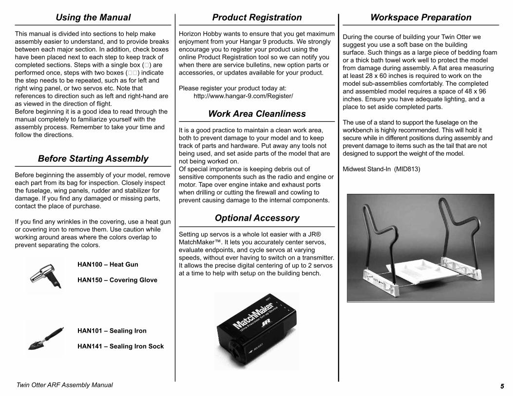
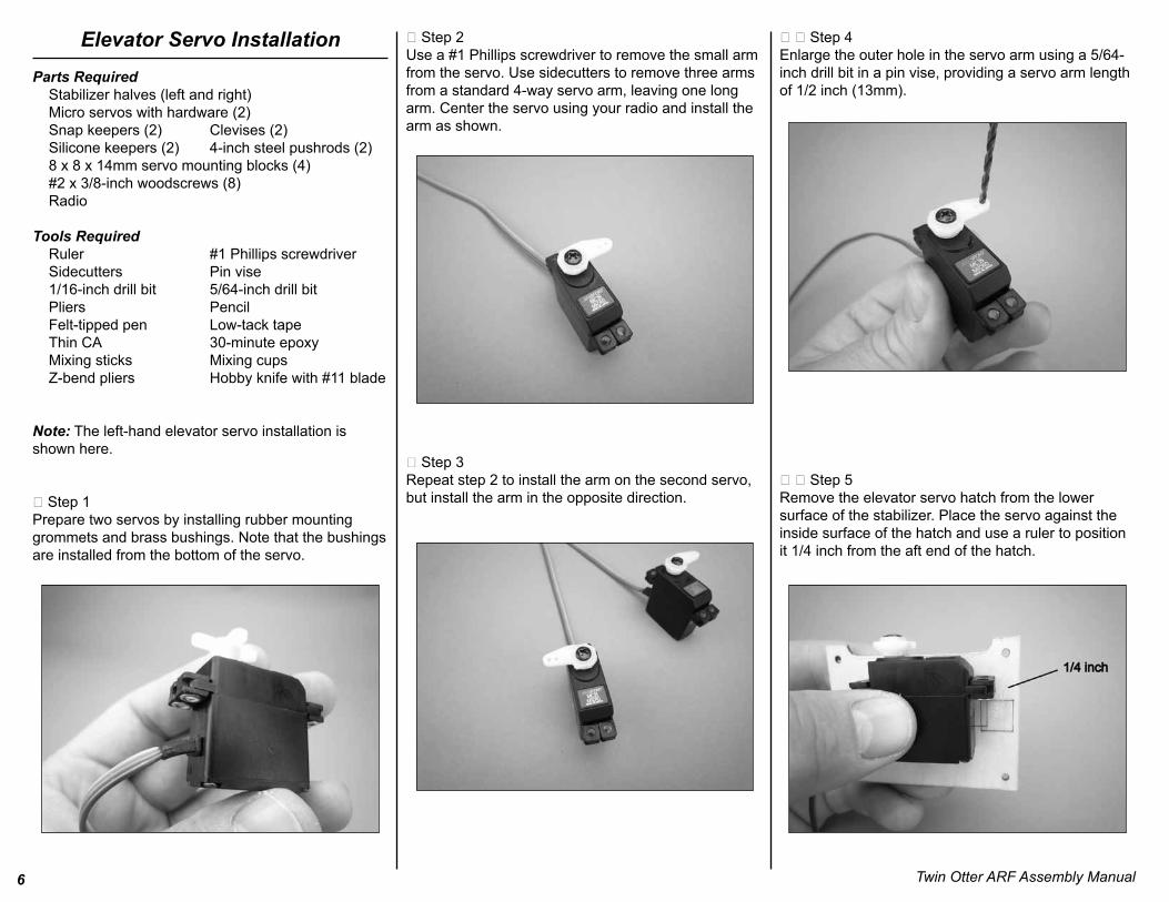
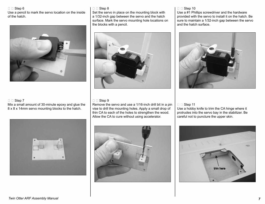
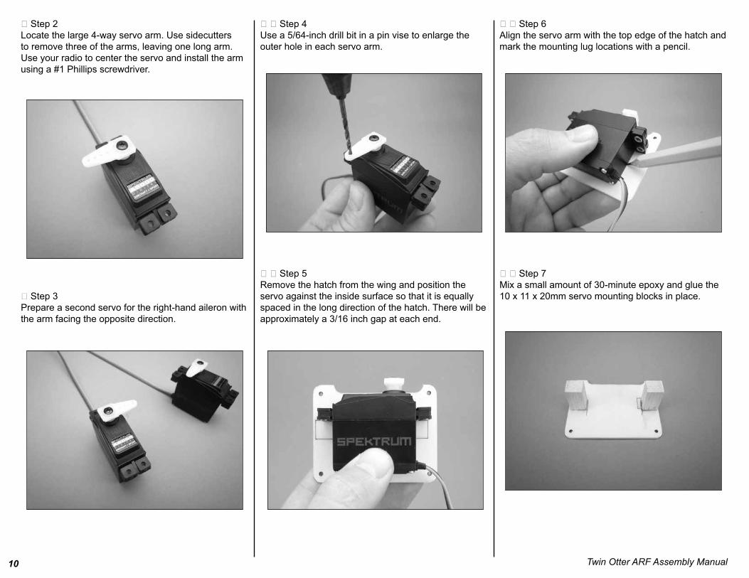
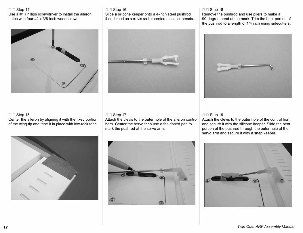
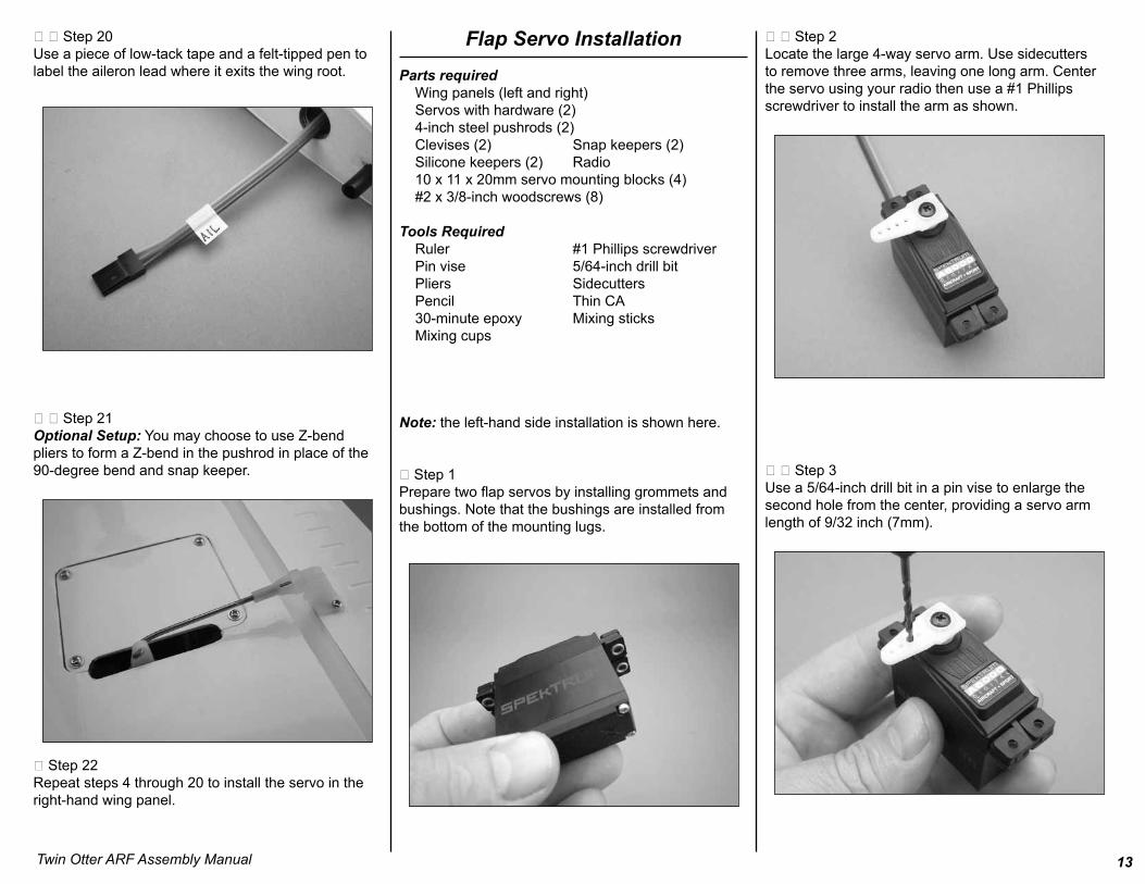
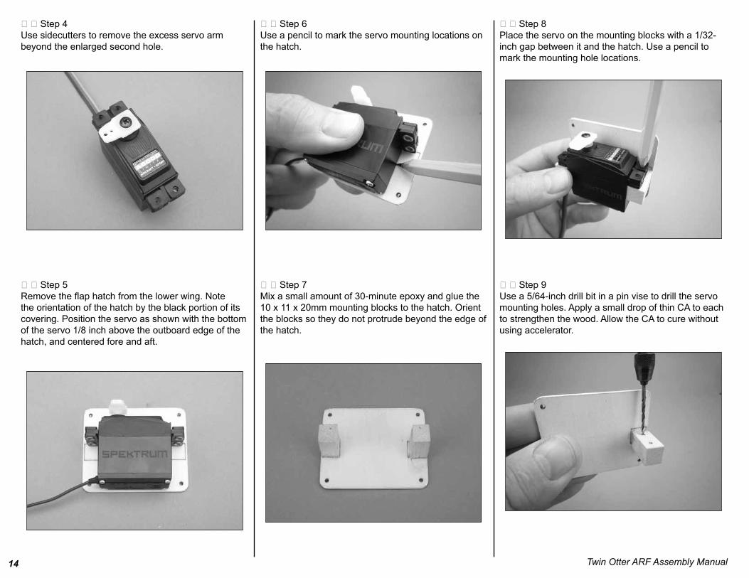
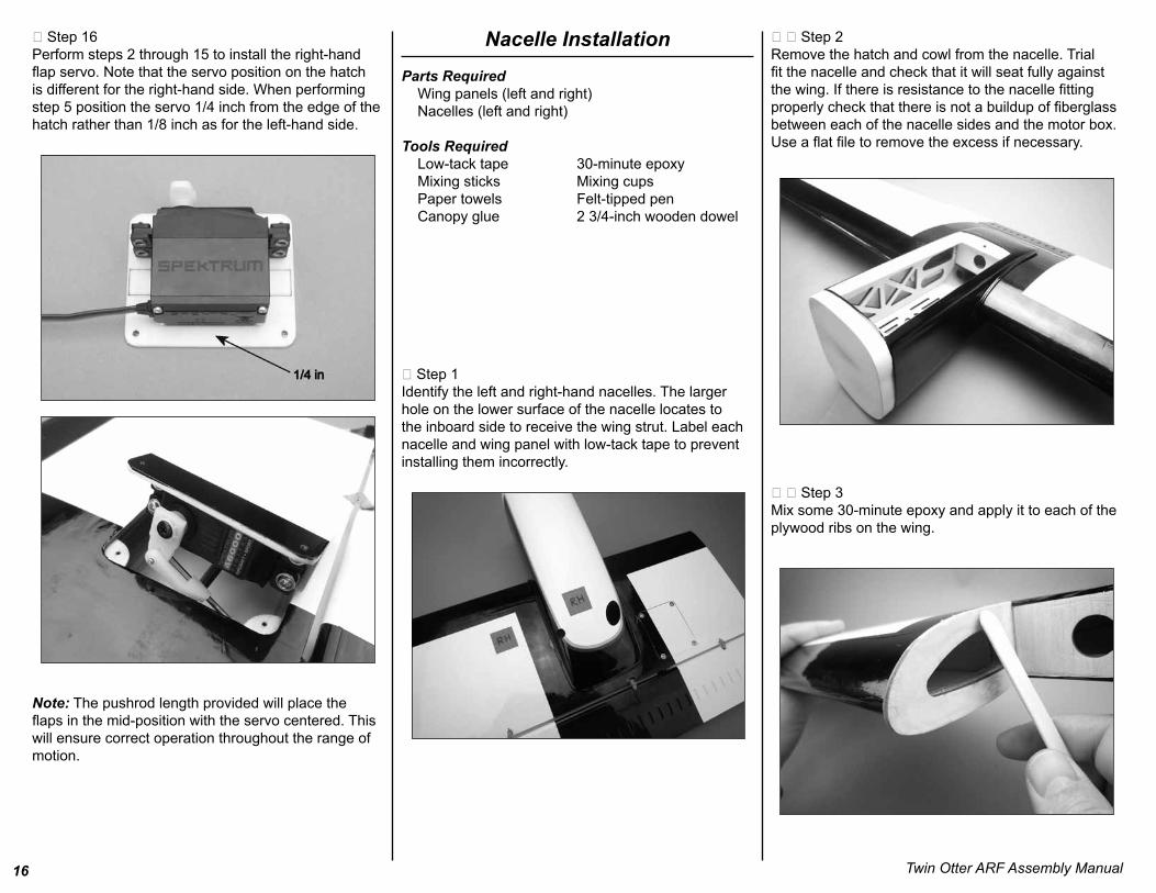
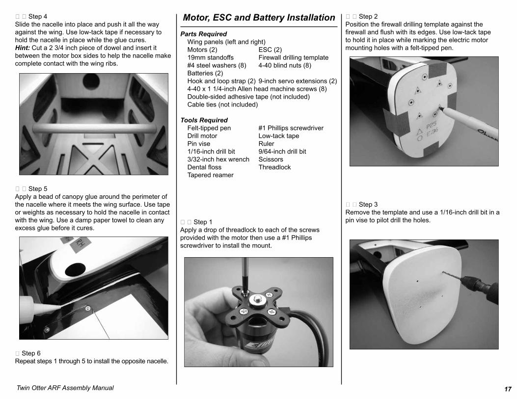
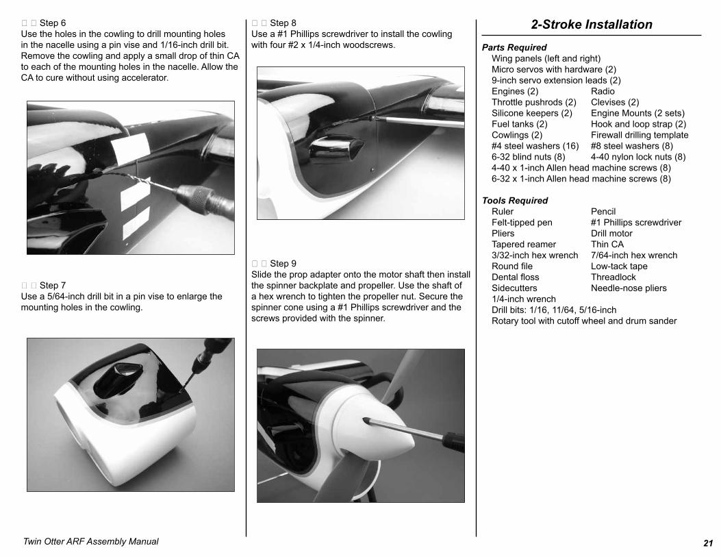
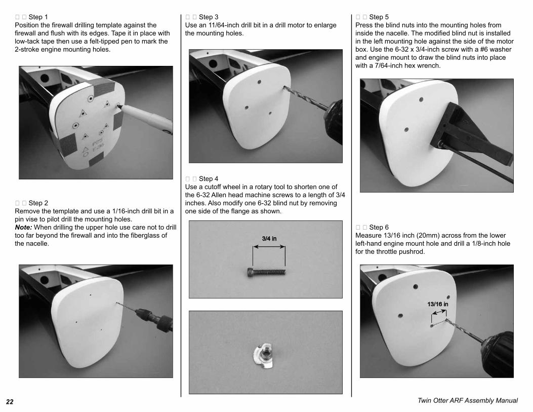
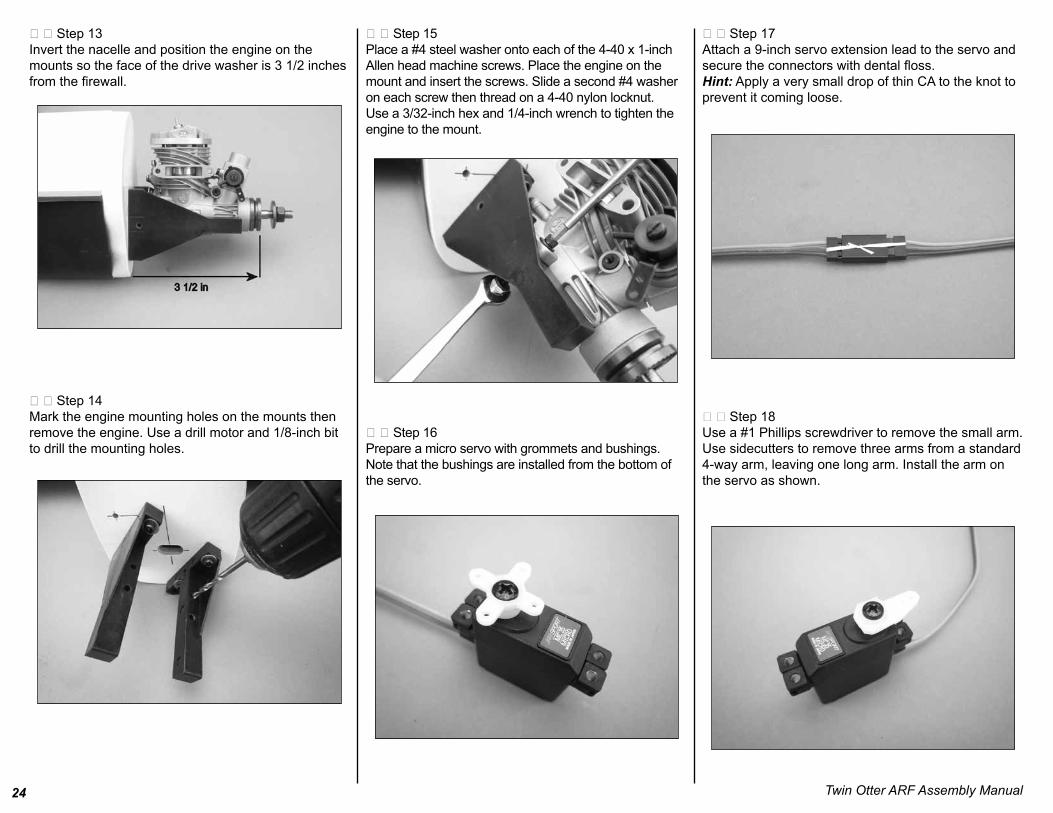
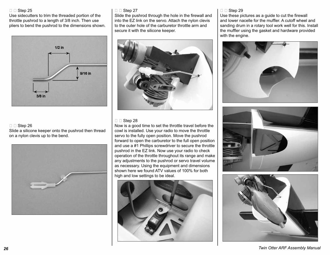
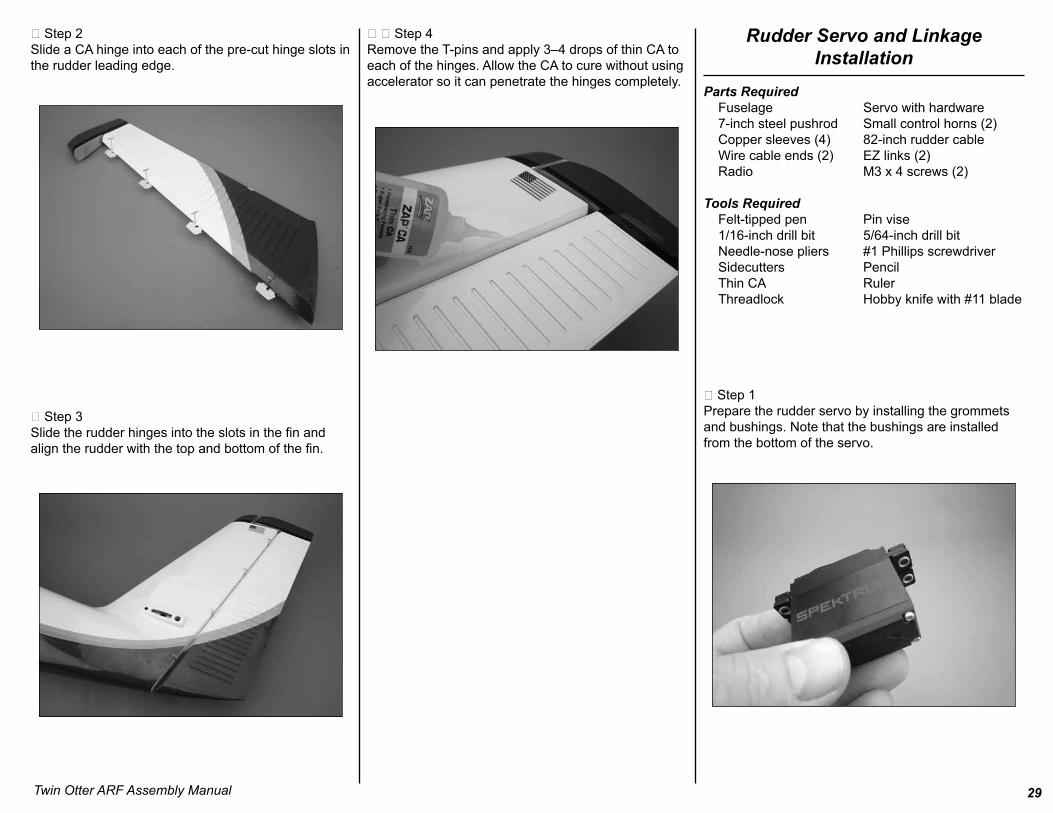
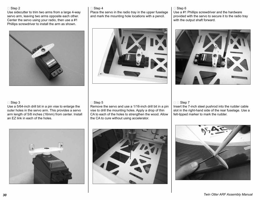
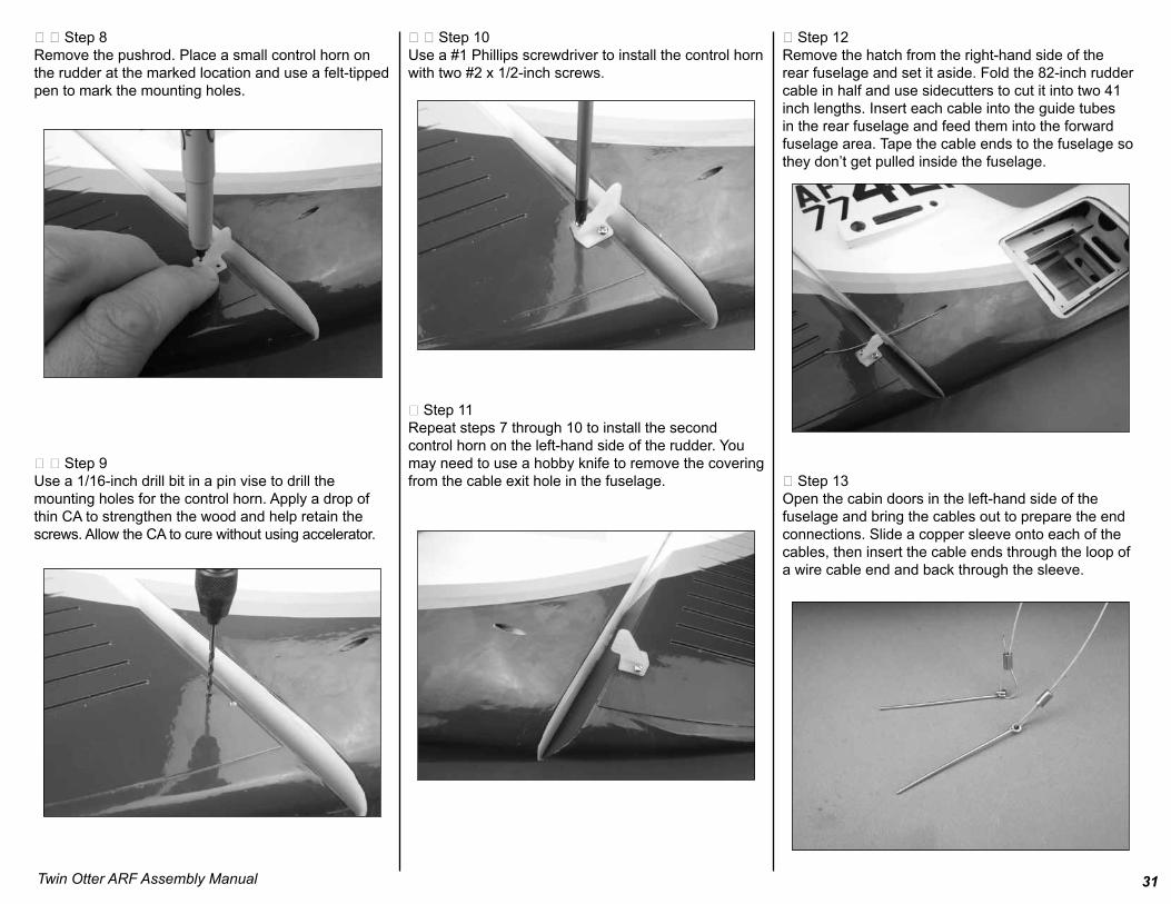
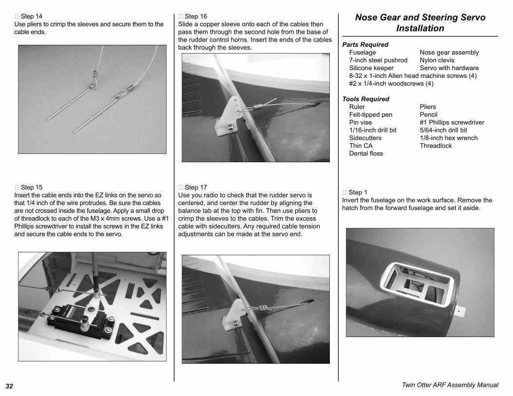
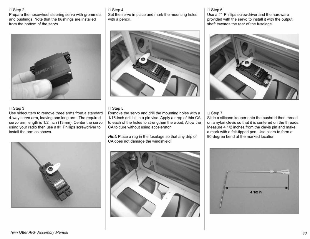
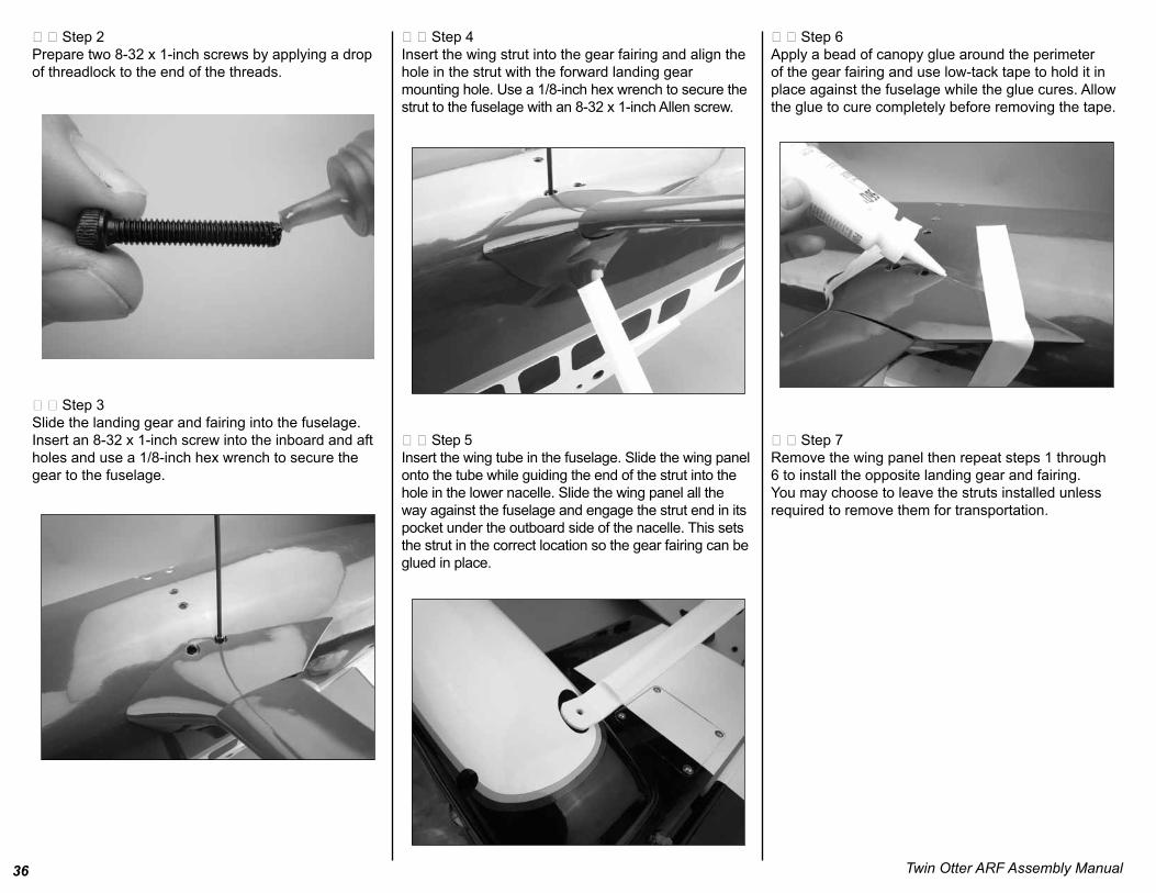