assembly and operating manual ers 135 - 210 / 560v
TRANSCRIPT

Translation of Original Operating Manual
Assembly and Operating ManualERS 135 - 210 / 560VElectrical turning unit with torque motor
Imprint
2 04.00 | ERS 135 - 210 / 560V | Assembly and Operating Manual | en | 389064
ImprintCopyright:This manual is protected by copyright. The author is SCHUNK GmbH & Co. KG. All rightsreserved.
Technical changes:We reserve the right to make alterations for the purpose of technical improvement.
Document number: 389064
Version: 04.00 | 18/01/2021 | en
Dear Customer,thank you for trusting our products and our family-owned company, the leadingtechnology supplier of robots and production machines.Our team is always available to answer any questions on this product and other solutions.Ask us questions and challenge us. We will find a solution!Best regards,Your SCHUNK team
Customer ManagementTel. +49-7133-103-2500Fax [email protected]
Please read the operating manual in full and keep it close to the product.

Table of Contents
Table of Contents1 General.................................................................................................................... 5
1.1 About this manual ................................................................................................ 51.1.1 Presentation of Warning Labels ............................................................... 51.1.2 Applicable documents .............................................................................. 61.1.3 Sizes .......................................................................................................... 61.1.4 Versions .................................................................................................... 6
1.2 Warranty .............................................................................................................. 61.3 Scope of delivery .................................................................................................. 61.4 Accessories ........................................................................................................... 7
2 Basic safety notes ................................................................................................... 82.1 Intended use......................................................................................................... 82.2 Not intended use.................................................................................................. 82.3 Constructional changes ........................................................................................ 82.4 Spare parts ........................................................................................................... 82.5 Ambient conditions and operating conditions ..................................................... 9
2.5.1 Electromagnetic compatibility.................................................................. 92.6 Personnel qualification......................................................................................... 92.7 Personal protective equipment.......................................................................... 102.8 Notes on safe operation ..................................................................................... 102.9 Transport ............................................................................................................ 112.10 Malfunctions....................................................................................................... 112.11 Disposal .............................................................................................................. 112.12 Fundamental dangers......................................................................................... 11
2.12.1 Protection during handling and assembly .............................................. 122.12.2 Protection during commissioning and operation ................................... 122.12.3 Protection against dangerous movements............................................. 132.12.4 Protection against electric shock............................................................ 14
2.13 Notes on particular risks..................................................................................... 15
3 Technical data......................................................................................................... 173.1 Type key and name plate ................................................................................... 173.2 Basic data ........................................................................................................... 183.3 Diagram for variants without DDF and without IP54 ......................................... 203.4 Pneumatic holding brake variant........................................................................ 223.5 Rotary feed-through (DDF) variant..................................................................... 233.6 SCHUNK power and sensor cable ....................................................................... 23
304.00 | ERS 135 - 210 / 560V | Assembly and Operating Manual | en | 389064
Table of Contents
4 Design and description............................................................................................ 244.1 Design ................................................................................................................. 24
4.1.1 Pneumatic holding brake variant............................................................ 244.1.2 Rotary feed-through (DDF) variant......................................................... 25
4.2 Description ......................................................................................................... 26
5 Assembly ................................................................................................................ 285.1 Installing and connecting.................................................................................... 28
5.1.1 Pneumatic holding brake variant............................................................ 295.1.2 Rotary feed-through (DDF) variant......................................................... 33
5.2 Connections........................................................................................................ 345.2.1 Mechanical connection........................................................................... 345.2.2 Electrical connection .............................................................................. 40
6 Troubleshooting ..................................................................................................... 466.1 Product not turning ............................................................................................ 466.2 Product is having control difficulties. ................................................................. 476.3 Product is vibrating............................................................................................. 476.4 Bearing noise ...................................................................................................... 476.5 Error message for the winding temperature...................................................... 47
7 Maintenance .......................................................................................................... 497.1 Maintenance intervals........................................................................................ 497.2 Servicing the product ......................................................................................... 497.3 Disassembly and assembling .............................................................................. 50
8 Translation of original declaration of incorporation ................................................ 518.1 Annex to Declaration of Incorporation............................................................... 52
4 04.00 | ERS 135 - 210 / 560V | Assembly and Operating Manual | en | 389064

General
1 General1.1 About this manual
This manual contains important information for a safe andappropriate use of the product.This manual is an integral part of the product and must be keptaccessible for the personnel at all times.Before starting work, the personnel must have read andunderstood this operating manual. Prerequisite for safe working isthe observance of all safety instructions in this manual.Illustrations in this manual are provided for basic understandingand may differ from the actual product design.In addition to these instructions, the documents listed underApplicable documents [} 6] are applicable.
1.1.1 Presentation of Warning Labels
To make risks clear, the following signal words and symbols areused for safety notes.
DANGERDanger for persons!Non-observance will inevitably cause irreversible injury or death.
WARNINGDangers for persons!Non-observance can lead to irreversible injury and even death.
CAUTIONDangers for persons!Non-observance can cause minor injuries.
CAUTIONMaterial damage!Information about avoiding material damage.
504.00 | ERS 135 - 210 / 560V | Assembly and Operating Manual | en | 389064

General
6 04.00 | ERS 135 - 210 / 560V | Assembly and Operating Manual | en | 389064
1.1.2 Applicable documents
• General terms of business*• Catalog data sheet of the purchased product*• Assembly and Operating manuals of the accessories*• Start-up instructions for ERS on IndraDrive CS *• Start-up instructions for SIEMENS SINAMICS converter *• Drive controller documentationThe documents marked with an asterisk (*) can be downloaded onour homepage schunk.com
1.1.3 Sizes
This operating manual applies to the following sizes:• ERS135, 560 V• ERS170, 560 V• ERS210, 560 V
1.1.4 Versions
This operating manual applies to the following variations:• ERS• ERS with pneumatic holding brake• ERS with rotary feed-through (DDF)• ERS with protection class IP54
1.2 WarrantyIf the product is used as intended, the warranty is valid for 24months from the ex-works delivery date under the followingconditions:• Observe the specified maintenance and lubrication intervals• Observe the ambient conditions and operating conditionsParts touching the workpiece and wear parts are not included inthe warranty.
1.3 Scope of deliveryThe scope of delivery includes• Electrical turning unit with torque motor ERS in the version
ordered• Start-up DVD for SCHUNK motors• Accessory packAdditionally for the variant with pneumatic brake:• 2x micro valve, MVK 15 3/2• Y distributor, 2x M8 3-pin to 1x M8 3-pin• Sensor cable, connection plug M8 3-pin to open wire strands,
length 1.5 m

General
1.4 AccessoriesThe following accessories, which must be ordered separately, arerequired for the product:• Power and sensor cables• Drive controllerFor operation, the following drive controllers are supported asstandard:• Bosch IndraDrive C• Bosch IndraDrive CS• Siemens Sinamics S 120,
CU310-DP and S 120 CU320-DP control unitsFor information regarding which accessory articles can be usedwith the corresponding product variants, see catalog data sheet.
704.00 | ERS 135 - 210 / 560V | Assembly and Operating Manual | en | 389064

Basic safety notes
8 04.00 | ERS 135 - 210 / 560V | Assembly and Operating Manual | en | 389064
2 Basic safety notes2.1 Intended use
The product was designed to rotate loads, workpieces and objects.The poduct may only be operated in combination with acontroller.• The product may only be used within the scope of its technical
data.• The product is intended for installation in a machine/system.
The applicable guidelines must be observed and complied with.• The product is intended for industrial and industry-oriented use.• Appropriate use of the product includes compliance with all
instructions in this manual.
2.2 Not intended useIt is not intended use if the product is used, for example, as apressing tool, stamping tool, lifting gear, guide for tools, cuttingtool, clamping device or a drilling tool.• Any utilization that exceeds or differs from the appropriate use
is regarded as misuse.
2.3 Constructional changesImplementation of structural changesBy conversions, changes, and reworking, e.g. additional threads,holes, or safety devices can impair the functioning or safety of theproduct or damage it.• Structural changes should only be made with the written
approval of SCHUNK.
2.4 Spare partsUse of unauthorized spare partsUsing unauthorized spare parts can endanger personnel anddamage the product or cause it to malfunction.• Use only original spare parts or spares authorized by SCHUNK.
Basic safety notes
2.5 Ambient conditions and operating conditionsRequired ambient conditions and operating conditionsIncorrect ambient and operating conditions can make the productunsafe, leading to the risk of serious injuries, considerable materialdamage and/or a significant reduction to the product's life span.• Make sure that the product is used only in the context of its
defined application parameters, Technical data [} 17].2.5.1 Electromagnetic compatibility
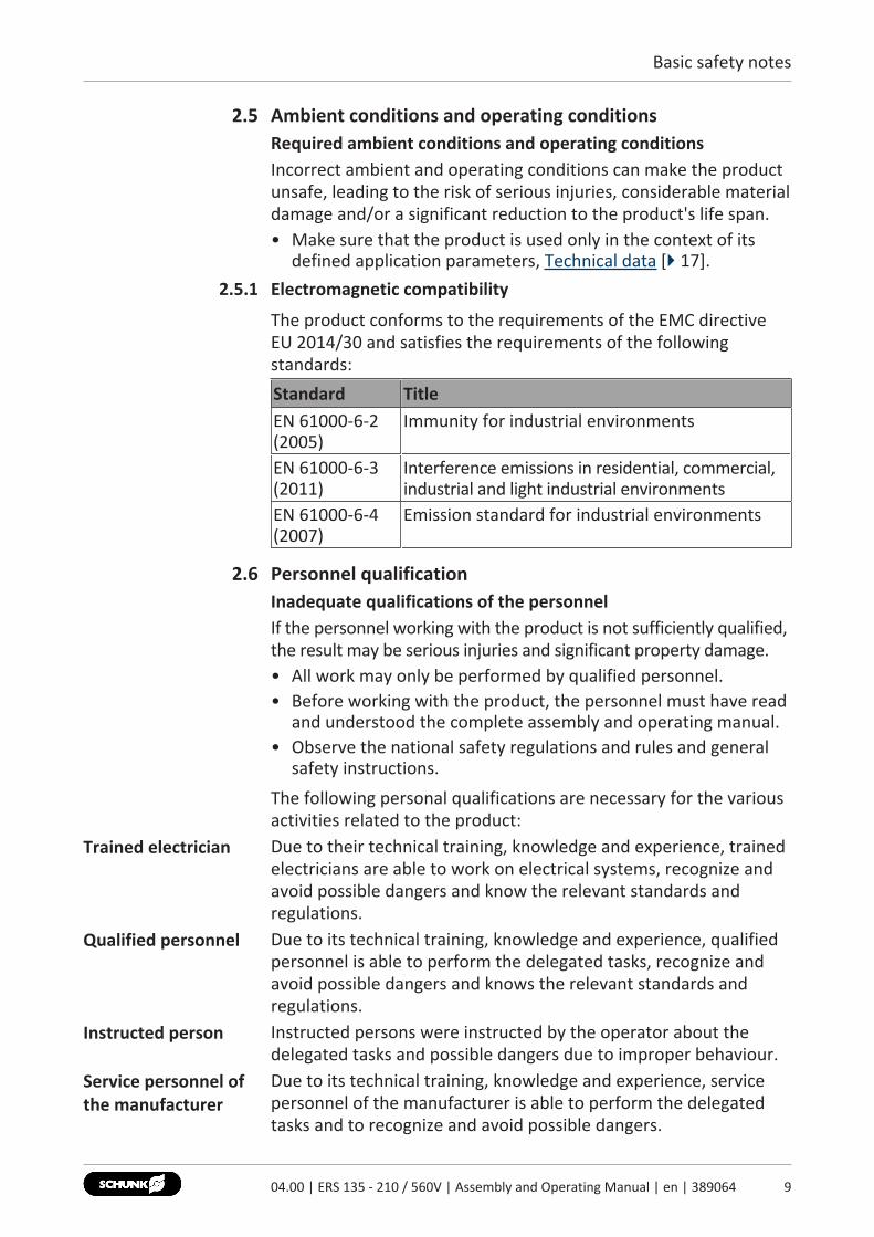
The product conforms to the requirements of the EMC directiveEU 2014/30 and satisfies the requirements of the followingstandards:Standard TitleEN 61000-6-2(2005)
Immunity for industrial environments
EN 61000-6-3(2011)
Interference emissions in residential, commercial,industrial and light industrial environments
EN 61000-6-4(2007)
Emission standard for industrial environments
2.6 Personnel qualificationInadequate qualifications of the personnelIf the personnel working with the product is not sufficiently qualified,the result may be serious injuries and significant property damage.• All work may only be performed by qualified personnel.• Before working with the product, the personnel must have read
and understood the complete assembly and operating manual.• Observe the national safety regulations and rules and general
safety instructions.The following personal qualifications are necessary for the variousactivities related to the product:
Trained electrician Due to their technical training, knowledge and experience, trainedelectricians are able to work on electrical systems, recognize andavoid possible dangers and know the relevant standards andregulations.
Qualified personnel Due to its technical training, knowledge and experience, qualifiedpersonnel is able to perform the delegated tasks, recognize andavoid possible dangers and knows the relevant standards andregulations.
Instructed person Instructed persons were instructed by the operator about thedelegated tasks and possible dangers due to improper behaviour.
Service personnel ofthe manufacturer
Due to its technical training, knowledge and experience, servicepersonnel of the manufacturer is able to perform the delegatedtasks and to recognize and avoid possible dangers.
904.00 | ERS 135 - 210 / 560V | Assembly and Operating Manual | en | 389064
Basic safety notes
10 04.00 | ERS 135 - 210 / 560V | Assembly and Operating Manual | en | 389064
2.7 Personal protective equipmentUse of personal protective equipmentPersonal protective equipment serves to protect staff againstdanger which may interfere with their health or safety at work.• When working on and with the product, observe the
occupational health and safety regulations and wear therequired personal protective equipment.
• Observe the valid safety and accident prevention regulations.• Wear protective gloves to guard against sharp edges and
corners or rough surfaces.• Wear heat-resistant protective gloves when handling hot
surfaces.• Wear protective gloves and safety goggles when handling
hazardous substances.• Wear close-fitting protective clothing and also wear long hair in
a hairnet when dealing with moving components.
2.8 Notes on safe operationIncorrect handling of the personnelIncorrect handling and assembly may impair the product's safetyand cause serious injuries and considerable material damage.• Avoid any manner of working that may interfere with the
function and operational safety of the product.• Use the product as intended.• Observe the safety notes and assembly instructions.• Do not expose the product to any corrosive media. This does
not apply to products that are designed for specialenvironments.
• Eliminate any malfunction immediately.• Observe the care and maintenance instructions.• Observe the current safety, accident prevention and
environmental protection regulations regarding the product'sapplication field.

Basic safety notes
2.9 TransportHandling during transportIncorrect handling during transport may impair the product'ssafety and cause serious injuries and considerable materialdamage.• When handling heavy weights, use lifting equipment to lift the
product and transport it by appropriate means.• Secure the product against falling during transportation and
handling.• Stand clear of suspended loads.
2.10 MalfunctionsBehavior in case of malfunctions• Immediately remove the product from operation and report the
malfunction to the responsible departments/persons.• Order appropriately trained personnel to rectify the
malfunction.• Do not recommission the product until the malfunction has
been rectified.• Test the product after a malfunction to establish whether it still
functions properly and no increased risks have arisen.
2.11 DisposalHandling of disposalThe incorrect handling of disposal may impair the product's safetyand cause serious injuries as well as considerable material andenvironmental harm.• Follow local regulations on dispatching product components for
recycling or proper disposal.
2.12 Fundamental dangersGeneral• Observe safety distances.• Never deactivate safety devices.• Before commissioning the product, take appropriate protective
measures to secure the danger zone.• Disconnect power sources before installation, modification,
maintenance, or calibration. Ensure that no residual energyremains in the system.
• If the energy supply is connected, do not move any parts by hand.• Do not reach into the open mechanism or movement area of
the product during operation.
1104.00 | ERS 135 - 210 / 560V | Assembly and Operating Manual | en | 389064
Basic safety notes
12 04.00 | ERS 135 - 210 / 560V | Assembly and Operating Manual | en | 389064
2.12.1 Protection during handling and assembly
Incorrect handling and assemblyIncorrect handling and assembly may impair the product's safetyand cause serious injuries and considerable material damage.• Have all work carried out by appropriately qualified personnel.• For all work, secure the product against accidental operation.• Observe the relevant accident prevention rules.• Use suitable assembly and transport equipment and take
precautions to prevent jamming and crushing.Incorrect lifting of loadsFalling loads may cause serious injuries and even death.• Stand clear of suspended loads and do not step into their
swiveling range.• Never move loads without supervision.• Do not leave suspended loads unattended.
2.12.2 Protection during commissioning and operation
Falling or violently ejected componentsFalling and violently ejected components can cause serious injuriesand even death.• Take appropriate protective measures to secure the danger
zone.• Never step into the danger zone during operation.
Basic safety notes
2.12.3 Protection against dangerous movements
Unexpected movementsResidual energy in the system may cause serious injuries whileworking with the product.• Switch off the energy supply, ensure that no residual energy
remains and secure against inadvertent reactivation.• The faulty actuation of conected drives may cause dangerous
movements.• Operating mistakes, faulty parameterization during
commissioning or software errors may trigger dangerousmovements.
• Never rely solely on the response of the monitoring function toavert danger. Until the installed monitors become effective, itmust be assumed that the drive movement is faulty, with itsaction being dependent on the control unit and the currentoperating condition of the drive. Perform maintenance work,modifications, and attachments outside the danger zonedefined by the movement range.
• To avoid accidents and/or material damage, human access tothe movement range of the machine must be restricted. Limit/prevent accidental access for people in this area due throughtechnical safety measures. The protective cover and protectivefence must be rigid enough to withstand the maximum possiblemovement energy. EMERGENCY STOP switches must be easilyand quickly accessible. Before starting up the machine orautomated system, check that the EMERGENCY STOP system isworking. Prevent operation of the machine if this protectiveequipment does not function correctly.
1304.00 | ERS 135 - 210 / 560V | Assembly and Operating Manual | en | 389064
Basic safety notes
14 04.00 | ERS 135 - 210 / 560V | Assembly and Operating Manual | en | 389064
2.12.4 Protection against electric shock
Work on electrical equipmentTouching live parts may result in death.• Work on the electrical equipment may only be carried out by
qualified electricians in accordance with the electricalengineering regulations.
• Lay electrical cables properly, e. g. in a cable duct or a cablebridge. Observe standards.
• Before connecting or disconnecting electrical cables, switch offthe power supply and check that the cables are free of voltage.Secure the power supply against being switched on again.
• Before switching on the product, check that the protectiveearth conductor is correctly attached to all electricalcomponents according to the wiring diagram.
• Check whether covers and protective devices are fitted toprevent contact with live components.
• Do not touch the product's terminals when the power supply isswitched on.
Possible electrostatic energyComponents or assembly groups may become electrostaticallycharged. When the electrostatic charge is touched, the dischargemay trigger a shock reaction leading to injuries.• The operator must ensure that all components and assembly
groups are included in the local potential equalisation inaccordance with the applicable regulations.
• While paying attention to the actual conditions of the workingenvironment, the potential equalisation must be implementedby a specialist electrician according to the applicableregulations.
• The effectiveness of the potential equalisation must be verifiedby executing regular safety measurements.

Basic safety notes
2.13 Notes on particular risks
DANGERDanger from electric voltage!Touching live parts may result in death.• Switch off the power supply before any assembly, adjustment
or maintenance work and secure against being switched onagain.
• Only qualified electricians may perform electrical installations.• Check if de-energized, ground it and hot-wire.• Cover live parts.
DANGERRisk of fatal injury from suspended loads!Falling loads can cause serious injuries and even death.• Stand clear of suspended loads and do not step within their
swiveling range.• Never move loads without supervision.• Do not leave suspended loads unattended.• Wear suitable protective equipment.
WARNINGRisk of injury from objects falling and being ejected!Falling and ejected objects during operation can lead to seriousinjury or death.• Take appropriate protective measures to secure the danger
zone.
WARNINGRisk of injury due to unexpected movements!If the power supply is switched on or residual energy remains inthe system, components can move unexpectedly and causeserious injuries.• Before starting any work on the product: Switch off the power
supply and secure against restarting.• Make sure, that no residual energy remains in the system.
1504.00 | ERS 135 - 210 / 560V | Assembly and Operating Manual | en | 389064
Basic safety notes
16 04.00 | ERS 135 - 210 / 560V | Assembly and Operating Manual | en | 389064
WARNINGRisk of burns through contact with hot surfaces!Surfaces of components can heat up severely during operation.Skin contact with hot surfaces causes severe burns to the skin.• For all work in the vicinity of hot surfaces, wear safety gloves.• Before carrying out any work, make sure that all surfaces have
cooled down to the ambient temperature.
WARNINGRisk of injury due to moving parts if these are controlledincorrectlyPossible causes for control errors:• Incorrect cabling or wiring• Removal of safety devices• Software errors• Sensor and signal transmitter errors• Entry of incorrect parameters prior to start-up• Defective product

Technical data
3 Technical data3.1 Type key and name plate
ERS 210
sizeERS 135 ERS 170 ERS 210
voltage
IP rating
- 560
rated motor voltage = 560 Vrated motor voltage = 48 V
- 40
IP = 40IP = 54
pneumatic holding brake
- B
N = without pneumatic holding brakeB = with pneumatic holding brake
rotor
- N
N = without rotorD = with rotor
measuring system
- I
I = incremental
Type key
The name plate is attached to the curve of the product.Specifications on the name plate (example ERS 210 560V)
Designation SpecificationManufacturer SCHUNK GmbH & Co. KGType/model - protection class ERS210-560-40-B-N-IID 0310xxxRated torque (MN) 10 NmVoltage (UN) 560 VCurrent (IN) 1.8 A
1704.00 | ERS 135 - 210 / 560V | Assembly and Operating Manual | en | 389064
Technical data
18 04.00 | ERS 135 - 210 / 560V | Assembly and Operating Manual | en | 389064
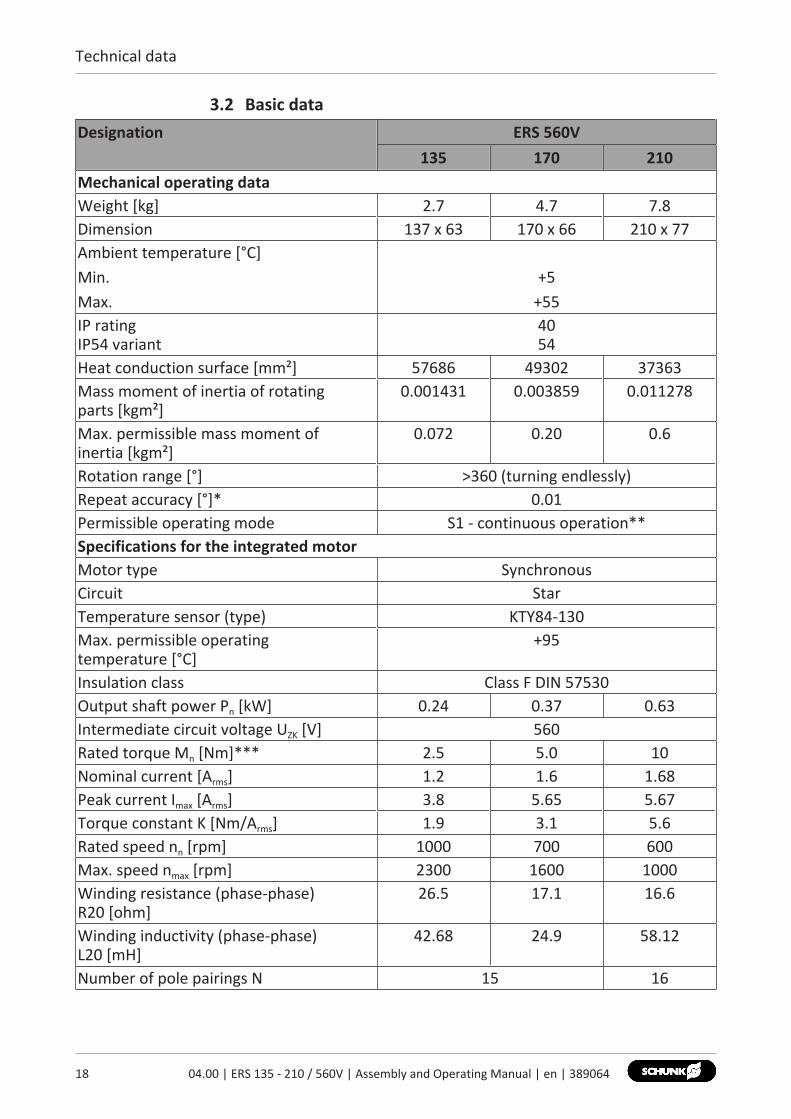
3.2 Basic dataDesignation ERS 560V
135 170 210Mechanical operating dataWeight [kg] 2.7 4.7 7.8Dimension 137 x 63 170 x 66 210 x 77Ambient temperature [°C]Min.Max.
+5+55
IP ratingIP54 variant
4054
Heat conduction surface [mm²] 57686 49302 37363Mass moment of inertia of rotating parts [kgm²]
0.001431 0.003859 0.011278
Max. permissible mass moment of inertia [kgm²]
0.072 0.20 0.6
Rotation range [°] >360 (turning endlessly)Repeat accuracy [°]* 0.01Permissible operating mode S1 - continuous operation**Specifications for the integrated motorMotor type SynchronousCircuit StarTemperature sensor (type) KTY84-130Max. permissible operating temperature [°C]
+95
Insulation class Class F DIN 57530Output shaft power Pn [kW] 0.24 0.37 0.63Intermediate circuit voltage UZK [V] 560Rated torque Mn [Nm]*** 2.5 5.0 10Nominal current [Arms] 1.2 1.6 1.68Peak current Imax [Arms] 3.8 5.65 5.67Torque constant K [Nm/Arms] 1.9 3.1 5.6Rated speed nn [rpm] 1000 700 600Max. speed nmax [rpm] 2300 1600 1000Winding resistance (phase-phase) R20 [ohm]
26.5 17.1 16.6
Winding inductivity (phase-phase) L20 [mH]
42.68 24.9 58.12
Number of pole pairings N 15 16
Technical data
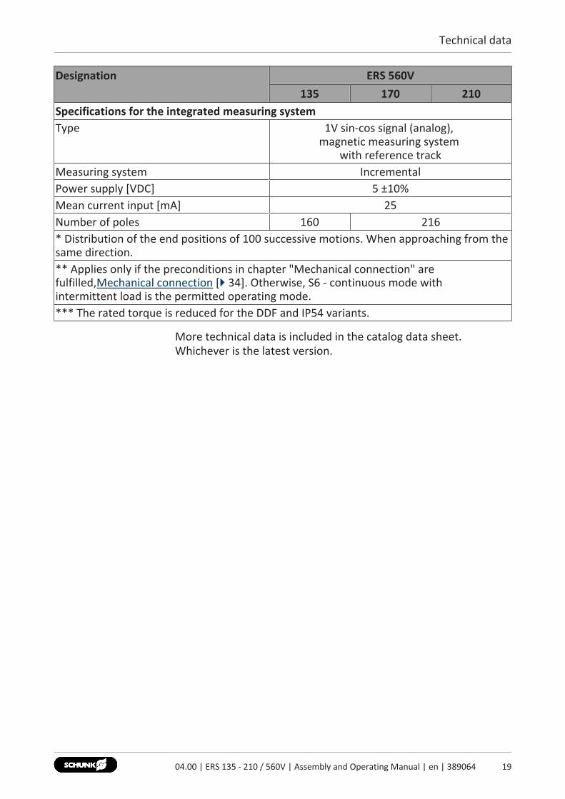
Designation ERS 560V135 170 210
Specifications for the integrated measuring systemType 1V sin-cos signal (analog),
magnetic measuring system with reference track
Measuring system IncrementalPower supply [VDC] 5 ±10%Mean current input [mA] 25Number of poles 160 216* Distribution of the end positions of 100 successive motions. When approaching from thesame direction.** Applies only if the preconditions in chapter "Mechanical connection" arefulfilled,Mechanical connection [} 34]. Otherwise, S6 - continuous mode withintermittent load is the permitted operating mode.*** The rated torque is reduced for the DDF and IP54 variants.
More technical data is included in the catalog data sheet.Whichever is the latest version.
1904.00 | ERS 135 - 210 / 560V | Assembly and Operating Manual | en | 389064
Technical data
20 04.00 | ERS 135 - 210 / 560V | Assembly and Operating Manual | en | 389064
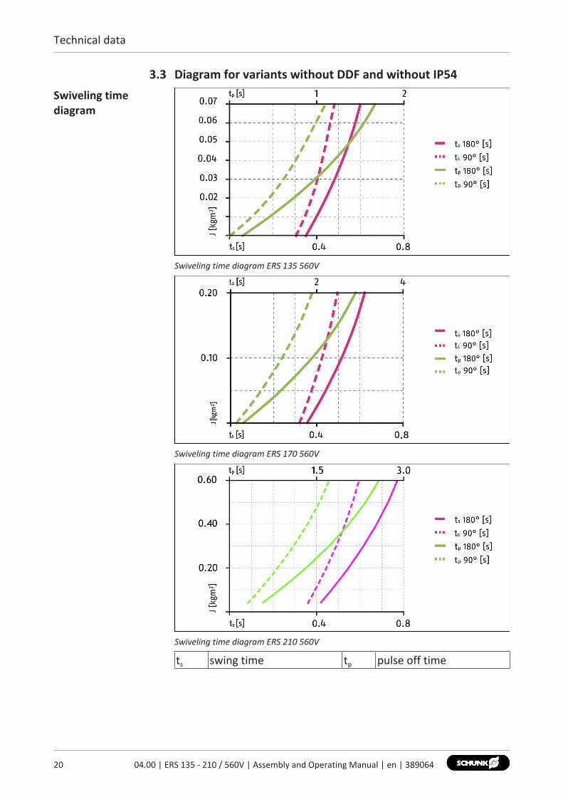
3.3 Diagram for variants without DDF and without IP54Swiveling timediagram
Swiveling time diagram ERS 135 560V
Swiveling time diagram ERS 170 560V
Swiveling time diagram ERS 210 560V
ts swing time tp pulse off time
Technical data
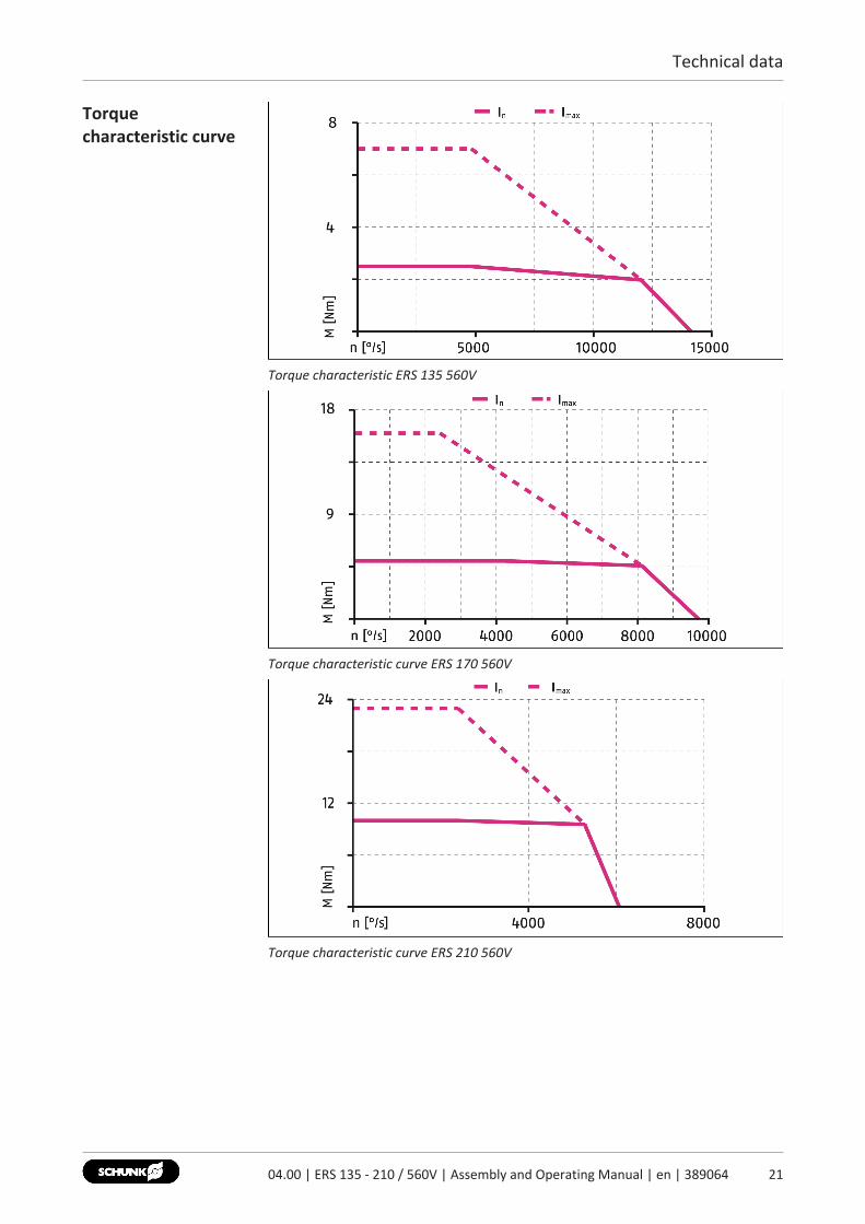
Torquecharacteristic curve
Torque characteristic ERS 135 560V
Torque characteristic curve ERS 170 560V
Torque characteristic curve ERS 210 560V
2104.00 | ERS 135 - 210 / 560V | Assembly and Operating Manual | en | 389064

Technical data
22 04.00 | ERS 135 - 210 / 560V | Assembly and Operating Manual | en | 389064
3.4 Pneumatic holding brake variantwithout micro valve Pneumatic brake without micro valve MV15
Designation ERS135 170 210
Brake torque [Nm] 2.5 5.0 10.0Opening/closing time ofthe brake at 4.5 bar [ms]OpeningClosing
100100
200200
100100
Air connectionspecifications
Thread M5, depth 8mm
Pressure medium Filtered compressed air, oiled or dry,compressed air purity
acc. to ISO 8573‐1:2010 [7:4:4]Operating pressure P[bar]
4.5 - 6
with micro valve Pneumatic brake with micro valve MV15
Designation ERS135 170 210
Brake torque [Nm] 2.5 5.0 10.0Opening/closing time ofthe brake at 4.5 bar [ms]OpeningClosing
100100
200200
100100
Hose connectiondiameter internal [mm]
4
Pressure medium Filtered compressed air, oiled or dry,compressed air purity
acc. to ISO 8573‐1:2010 [7:4:4]Operating pressure P[bar]
4.5 - 6
Power consumption [W] 2.8Nominal voltage [VDC] 24 (+10% / -5%)

Technical data
3.5 Rotary feed-through (DDF) variantDesignation ERS
170 210Rated torque Mn [Nm] 4.7 9.3Max. speed nmax [rpm] 250 250No. of fluid feed-throughs 1Max. pressure [bar] 8Max. flow quantity [l/min] 220Number of signal feed-throughs(incl. each 1x- power supply)
8
Max. Voltage [V] 24Max. current [A](per connection plug)
2
3.6 SCHUNK power and sensor cableCable type Power TransducerNumber of wires/cross-section 4x0.75 mm² +
2x0.25 mm²8x0.25 mm²
Max. voltage [V] 600 24Shielded yes yesShield around individual wirestrands
no yes
Twisted no yesTemperature application range[°C]
+5 to +55 +5 to +55
Max. cable length [m] 20 20Cable track compatibleMinimum bending radius 7.5 times the cable diameter
The catalog data sheet contains further information on the cableas well as a drawing of it.
2304.00 | ERS 135 - 210 / 560V | Assembly and Operating Manual | en | 389064
Design and description
24 04.00 | ERS 135 - 210 / 560V | Assembly and Operating Manual | en | 389064
4 Design and description4.1 Design
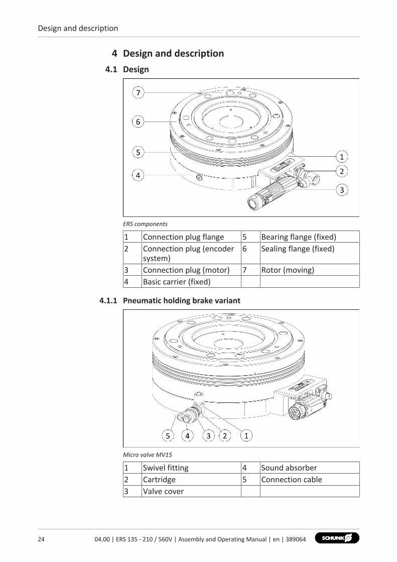
ERS components
1 Connection plug flange 5 Bearing flange (fixed)2 Connection plug (encoder
system)6 Sealing flange (fixed)
3 Connection plug (motor) 7 Rotor (moving)4 Basic carrier (fixed)
4.1.1 Pneumatic holding brake variant
Micro valve MV15
1 Swivel fitting 4 Sound absorber2 Cartridge 5 Connection cable3 Valve cover

Design and description
4.1.2 Rotary feed-through (DDF) variant
Assembly of the DDF
1 "Output side" flange2 Basic module3 "Input side" connection baseplate4 Centering groove
2504.00 | ERS 135 - 210 / 560V | Assembly and Operating Manual | en | 389064

Design and description
26 04.00 | ERS 135 - 210 / 560V | Assembly and Operating Manual | en | 389064
4.2 DescriptionThe product is an electrical turning unit with torque motor and acenter bore. The center bore can be used as a media feed-through.The product has an integrated position measuring system and atemperature sensor.The product must be operated using a drive controller. Thefollowing operating modes can be set.• Current-controlled• Speed-controlled• Position-controlledThe product is stored with the aid of a four point bearing. Thisbearing is lubricated via one-time grease lubrication.Under normal operating conditions, the grease lubrication issufficient for 20,000 operating hours, Maintenance intervals [} 49].
Rotary feed-through(DDF) variant
The variant with rotary feed-through (DDF), for sizes 170 and 210,is a combined pneumatic and electrical feed-through to supplyproducts on the ERS assembly.
Pneumatic holdingbrake variant
For the variant with pneumatic holding brake, the rotary module isheld in the current position. To do this, the pneumatic holdingbrake applies the rated torque for holding position at standstill.
NOTEThe pneumatic holding brake is not a service brake.
The pneumatic holding brake is actuated using the micro valve.The micro valve is closed if there is no voltage at the micro valve.In this state, the pneumatic holding brake is active. The microvalve is opened if there is voltage at the micro valve. In this state,the pneumatic holding brake is inactive.
Protection class IP54variant
With the protection class IP54 variant, an additional seal is built inbetween the bearing flange and the rotor. During assembly, a sealmust also be attached in the groove on the top and bottom of theERS, to ensure the IP54 protection class is achieved.

Design and description
Connection diagram
UVW + PE encoder
controller
encoder
supplyvoltage
encoder
plug connection
encoder
basic
winding
temperature sensor KTY842
8
ERS schematic diagram
The schematic diagram shows the connection diagram of theproduct between drive, encoder and drive controller.
2704.00 | ERS 135 - 210 / 560V | Assembly and Operating Manual | en | 389064
Assembly
28 04.00 | ERS 135 - 210 / 560V | Assembly and Operating Manual | en | 389064
5 Assembly5.1 Installing and connecting
WARNINGRisk of injury due to unexpected movements!If the power supply is switched on or residual energy remains inthe system, components can move unexpectedly and causeserious injuries.• Before starting any work on the product: Switch off the power
supply and secure against restarting.• Make sure, that no residual energy remains in the system.
In order to achieve protection class IP 40, design the connectionstructure so that no chips, cooling water or dirt can enter theturning unit's connection area from the working area.1. Protection class IP54 variant: insert seal into the groove,
Protection class IP54 variant [} 39].2. Mount the product on a surface with good thermal conductive
properties, Mechanical connection [} 34].3. Check the flatness of the mounting surface,
Mechanical connection [} 34].4. Screw the turning unit to the machine/system,
Mechanical connection [} 34].✓ Make sure that the interfaces to attachments are clean and
undamaged.✓ Use suitable connecting elements (adapter plates) if
necessary.✓ Observe the permissible depth of engagement.✓ Observe the tightening torque for the mounting screws.
5. Connect the turning unit electrically,Electrical connection [} 40].✓ Screw the connection plug for power and sensor cable to
the turning unit.✓ Connect the power and sensor cable to the drive controller.
6. Pneumatic holding brake variant: assemble and connect microvalve, Installing the micro valve [} 31].
7. Assemble attachment output side.

Assembly
5.1.1 Pneumatic holding brake variant
WARNINGRisk of injury when working on the micro valve!Severe injuries can be caused with active power and compressedair supply.• Switch off the energy supply.• Switch off the compressed air supply.
CAUTIONDamage to valve cartridges, valve cover and accessories!Valve cartridge, valve cover and accessories can be damaged byusing tools.• Only install or remove the valve cartridge, valve cover and
accessories by hand.
Comply with the following procedure when mounting the micro valve:• If the micro valve is supplied as a complete component,
dismantle the micro valve into its individual components andthen install the individual components:– Dismantling the micro valve into its individual components,
Dismantling micro valve [} 30].– Installing the individual components,
Installing the micro valve [} 31].• If the micro valve is supplied in individual components, install
the individual components, Installing the micro valve [} 31].• Change the position of the screw cable,
Changing the position of the connection cable [} 32].
2904.00 | ERS 135 - 210 / 560V | Assembly and Operating Manual | en | 389064
Assembly
30 04.00 | ERS 135 - 210 / 560V | Assembly and Operating Manual | en | 389064
5.1.1.1 Dismantling micro valve
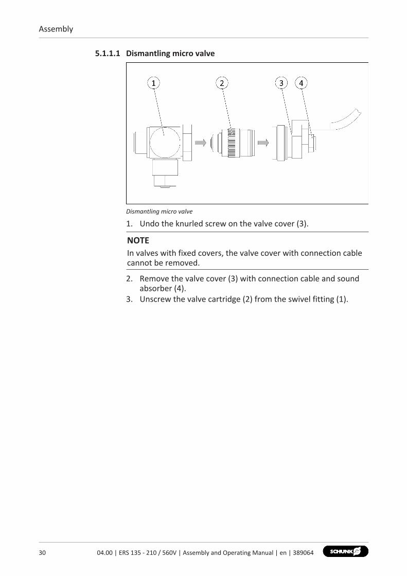
Dismantling micro valve
1. Undo the knurled screw on the valve cover (3).
NOTEIn valves with fixed covers, the valve cover with connection cablecannot be removed.
2. Remove the valve cover (3) with connection cable and soundabsorber (4).
3. Unscrew the valve cartridge (2) from the swivel fitting (1).
Assembly
5.1.1.2 Installing the micro valve
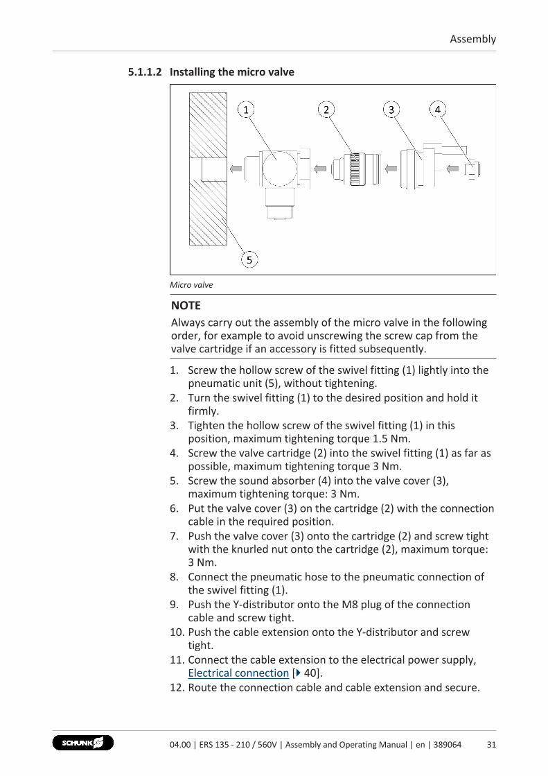
Micro valve
NOTEAlways carry out the assembly of the micro valve in the followingorder, for example to avoid unscrewing the screw cap from thevalve cartridge if an accessory is fitted subsequently.
1. Screw the hollow screw of the swivel fitting (1) lightly into thepneumatic unit (5), without tightening.
2. Turn the swivel fitting (1) to the desired position and hold itfirmly.
3. Tighten the hollow screw of the swivel fitting (1) in thisposition, maximum tightening torque 1.5 Nm.
4. Screw the valve cartridge (2) into the swivel fitting (1) as far aspossible, maximum tightening torque 3 Nm.
5. Screw the sound absorber (4) into the valve cover (3),maximum tightening torque: 3 Nm.
6. Put the valve cover (3) on the cartridge (2) with the connectioncable in the required position.
7. Push the valve cover (3) onto the cartridge (2) and screw tightwith the knurled nut onto the cartridge (2), maximum torque:3 Nm.
8. Connect the pneumatic hose to the pneumatic connection ofthe swivel fitting (1).
9. Push the Y‐distributor onto the M8 plug of the connectioncable and screw tight.
10. Push the cable extension onto the Y‐distributor and screwtight.
11. Connect the cable extension to the electrical power supply,Electrical connection [} 40].
12. Route the connection cable and cable extension and secure.
3104.00 | ERS 135 - 210 / 560V | Assembly and Operating Manual | en | 389064
Assembly
32 04.00 | ERS 135 - 210 / 560V | Assembly and Operating Manual | en | 389064
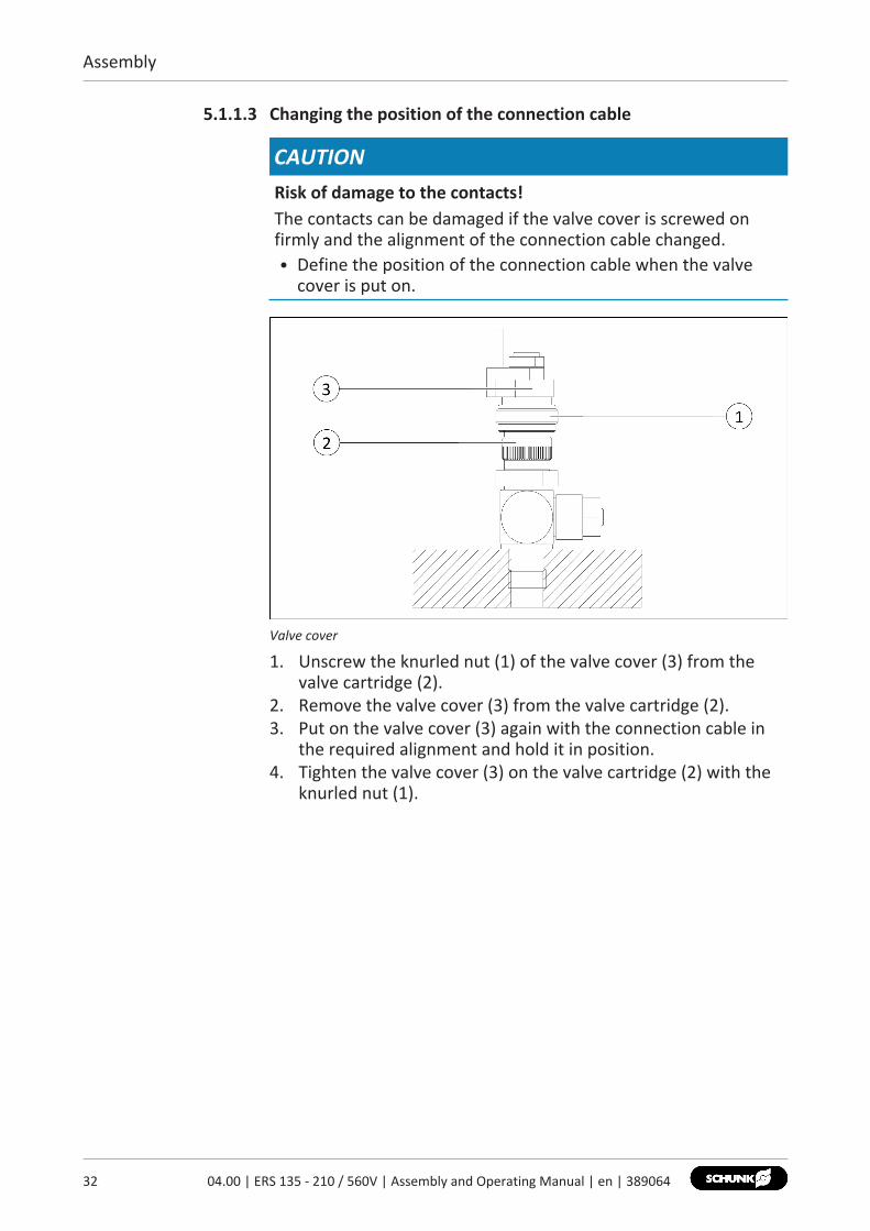
5.1.1.3 Changing the position of the connection cable
CAUTIONRisk of damage to the contacts!The contacts can be damaged if the valve cover is screwed onfirmly and the alignment of the connection cable changed.• Define the position of the connection cable when the valve
cover is put on.
Valve cover
1. Unscrew the knurled nut (1) of the valve cover (3) from thevalve cartridge (2).
2. Remove the valve cover (3) from the valve cartridge (2).3. Put on the valve cover (3) again with the connection cable in
the required alignment and hold it in position.4. Tighten the valve cover (3) on the valve cartridge (2) with the
knurled nut (1).
Assembly
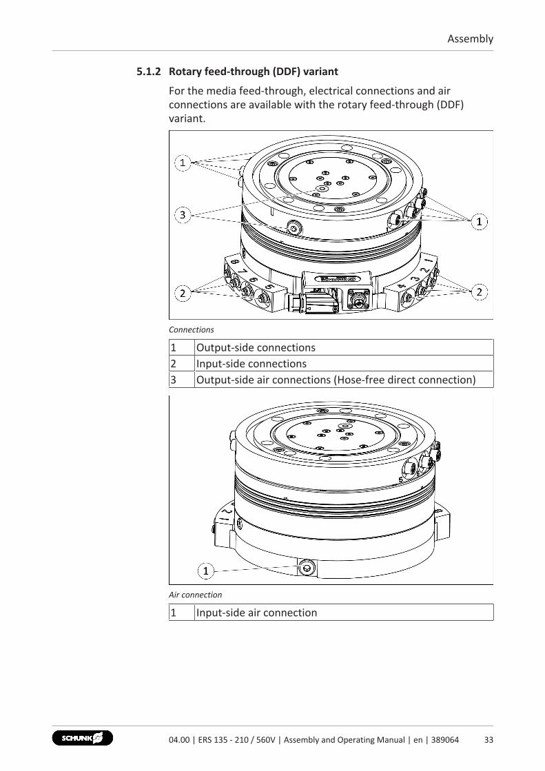
5.1.2 Rotary feed-through (DDF) variant
For the media feed-through, electrical connections and airconnections are available with the rotary feed-through (DDF)variant.
Connections
1 Output-side connections2 Input-side connections3 Output-side air connections (Hose-free direct connection)
Air connection
1 Input-side air connection
3304.00 | ERS 135 - 210 / 560V | Assembly and Operating Manual | en | 389064
Assembly
34 04.00 | ERS 135 - 210 / 560V | Assembly and Operating Manual | en | 389064
5.2 Connections
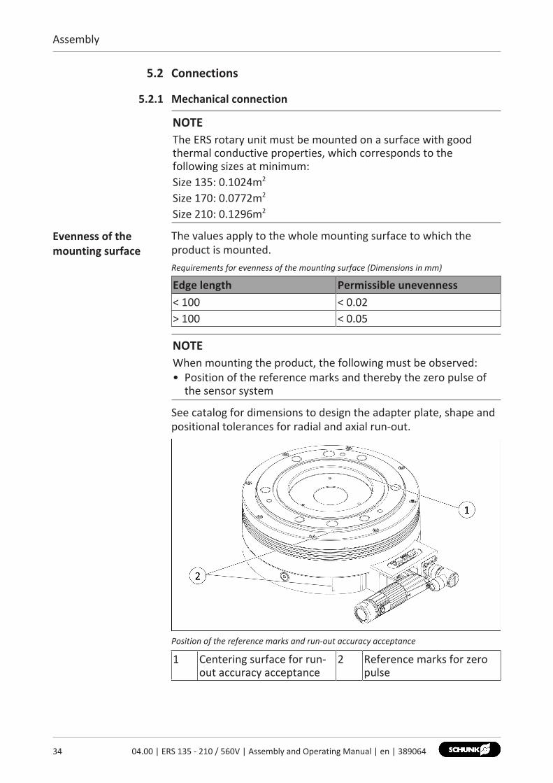
5.2.1 Mechanical connection
NOTEThe ERS rotary unit must be mounted on a surface with goodthermal conductive properties, which corresponds to thefollowing sizes at minimum:Size 135: 0.1024m2
Size 170: 0.0772m2
Size 210: 0.1296m2
Evenness of themounting surface
The values apply to the whole mounting surface to which theproduct is mounted.Requirements for evenness of the mounting surface (Dimensions in mm)
Edge length Permissible unevenness< 100 < 0.02> 100 < 0.05
NOTEWhen mounting the product, the following must be observed:• Position of the reference marks and thereby the zero pulse of
the sensor system
See catalog for dimensions to design the adapter plate, shape andpositional tolerances for radial and axial run-out.
Position of the reference marks and run-out accuracy acceptance
1 Centering surface for run-out accuracy acceptance
2 Reference marks for zeropulse
Assembly
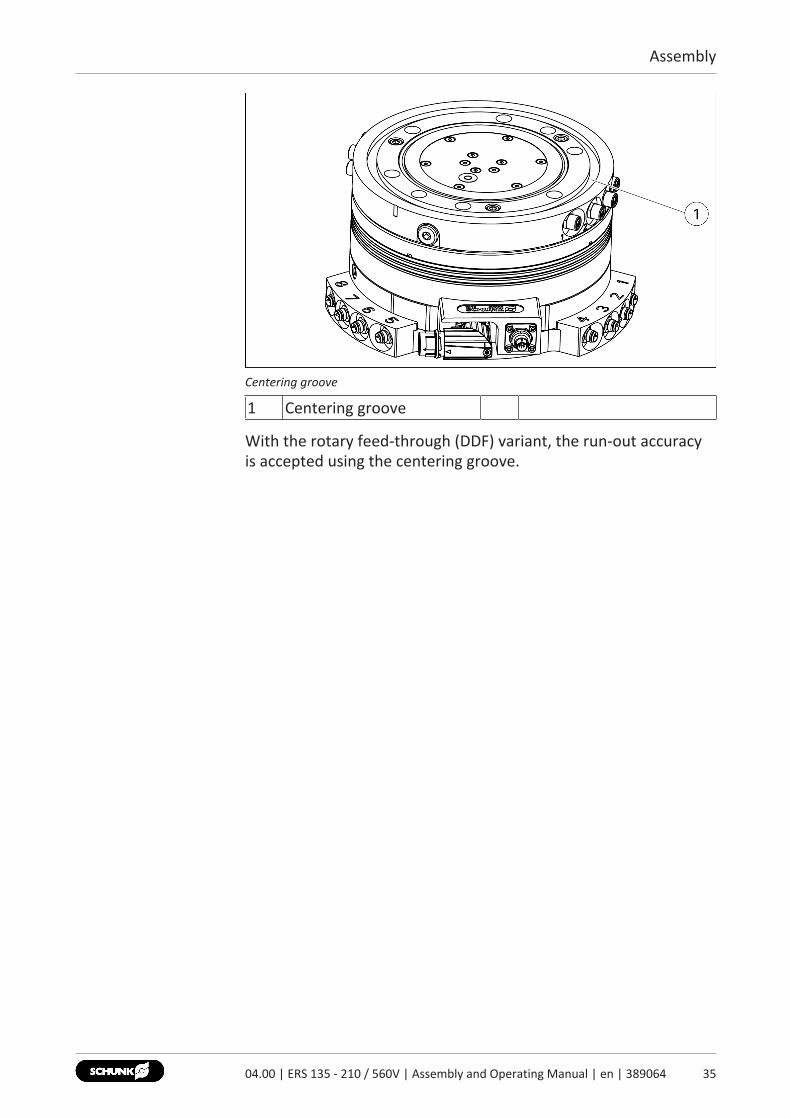
Centering groove
1 Centering groove
With the rotary feed-through (DDF) variant, the run-out accuracyis accepted using the centering groove.
3504.00 | ERS 135 - 210 / 560V | Assembly and Operating Manual | en | 389064

Assembly
36 04.00 | ERS 135 - 210 / 560V | Assembly and Operating Manual | en | 389064
Assembly view
Item Description ERS135 170 210
1 Mounting screws M8 M10 M10Tightening torque[Nm]
24 48 48
Max. depth ofengagement fromlocating surface[mm]
10 10 10
2 Centering pin Ø8 Ø10 Ø103 Centering pins Ø5 Ø5 Ø54 Mounting screws M8 M10 M12
Tightening torque[Nm]
24 48 84
Max. depth ofengagement fromlocating surface[mm]
13 14 18
Assembly
5.2.1.1 Pneumatic holding brake variant
WARNINGRisk of injury due to unexpected movement of the machine/system!The pneumatic holding brake is not a service brake and onlyapplies the rated torque for holding position at standstill. Withactive pneumatic holding brake and correspondingly highmoment load, components may move unexpectedly causingsevere injury.• Do not use the pneumatic holding brake as a service brake.• Do not use the pneumatic holding brake as a safety
component.
WARNINGRisk of injury when working on the micro valve!Severe injuries can be caused with active power and compressedair supply.• Switch off the energy supply.• Switch off the compressed air supply.
3704.00 | ERS 135 - 210 / 560V | Assembly and Operating Manual | en | 389064
Assembly
38 04.00 | ERS 135 - 210 / 560V | Assembly and Operating Manual | en | 389064
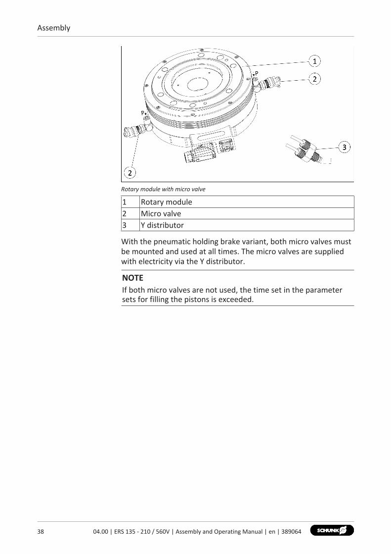
Rotary module with micro valve
1 Rotary module2 Micro valve3 Y distributor
With the pneumatic holding brake variant, both micro valves mustbe mounted and used at all times. The micro valves are suppliedwith electricity via the Y distributor.
NOTEIf both micro valves are not used, the time set in the parametersets for filling the pistons is exceeded.
Assembly
5.2.1.2 Protection class IP54 variant
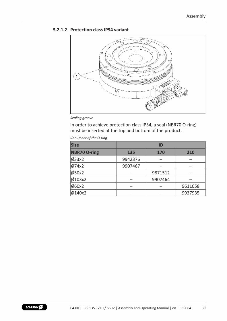
Sealing groove
In order to achieve protection class IP54, a seal (NBR70 O-ring)must be inserted at the top and bottom of the product.ID number of the O-ring
Size IDNBR70 O-ring 135 170 210Ø33x2 9942376 – –Ø74x2 9907467 – –Ø50x2 – 9871512 –Ø103x2 – 9907464 –Ø60x2 – – 9611058Ø140x2 – – 9937935
3904.00 | ERS 135 - 210 / 560V | Assembly and Operating Manual | en | 389064
Assembly
40 04.00 | ERS 135 - 210 / 560V | Assembly and Operating Manual | en | 389064
5.2.2 Electrical connection
DANGERRisk of fatal injuries due to electric shock!If the power supply is not switched off before working on theproduct, the drive controller is not separated from the powercables, or cables are connected incorrectly, fatal injury may becaused from electric shock.• Switch off energy supply before carrying out all assembly,
adjustment and maintenance work and secure against re-connection.
• Only allow qualified electricians to work on electricalautomated systems.
• Disconnect the drive controller from the power supply. Theintermediate circuit capacitors must be discharged. Wait forapprox. 15 minutes for the capacitors to discharge.
• Observe order when connecting the cables (first ground cable,then conductors).
CAUTIONDamage to the connection cable is possible!If the following preconditions are not observed when installingthe connection cables, the connection cable may becomedamaged• Install connection cables free from tensile and torsion loads. If
necessary, use cable guide chains.• Comply with the minimum bending radius (7.5 times the cable
diameter).• Install the connection cable so that the motor's range of
rotation and function are not impaired.
CAUTIONMaterial damage possible to lines!If the following prerequisites are not observed for installation oflines, the lines may be damaged.• When installing the lines, observe the specifications in the line
manufacturer data sheet.• During operation of the axes across the full stroke too, make
sure that the lines do not become crushed, sheared or torn off.• Install the power cable and measuring system lines in separate
cable tracks.

Assembly
Connectionassignment, powerconnector
Power connector, M17
Pin Signal Pin SignalPE Ground/motor housing 4 N. C.1 U 5 Temperature sensor 12 V 6 Temperature sensor 23 W
Sensor plugconnectionassignment
Sensor plug, M9
Pin Signal Pin Signal1 A (SIN +) 5 Z (Ref +)2 /A (SIN -) 6 /Z (Ref -)3 B (COS +) 7 GND4 /B (COS -) 8 Vcc
4104.00 | ERS 135 - 210 / 560V | Assembly and Operating Manual | en | 389064

Assembly
42 04.00 | ERS 135 - 210 / 560V | Assembly and Operating Manual | en | 389064
Bosch power andsensor cablesconnectionassignment
The cable colors and designations in the following tables apply tothe SCHUNK connection cable.Connection assignment of the blue power cable for Bosch Rexroth IndraDrive
Function Signal Cable designationPower U Black A1 (U)
V Black A2 (V)W Black A3 (W)PE Green /Yellow
Temperature sensor T1 RedT2 Blue
Connection assignment of the white sensor cable for Bosch IndraDrive Basic/Advanced
Function Signal Pin allocation – 15-pin Sub-Dsocket
Encoder /Z (Ref -) Pin 3Z (Ref +) Pin 4/B (COS -) Pin 5B (COS +) Pin 6A (SIN +) Pin 7/A (SIN -) Pin 8GND Pin 10Vcc Pin 12
Connection assignment of the white sensor cable for Bosch Rexroth IndraDrive CS
Function Signal Pin allocation – 15-pin Sub-Dsocket
Encoder A (SIN +) Pin 2/A (SIN -) Pin 3GND Pin 4B (COS +) Pin 5/B (COS -) Pin 6Z (Ref +) Pin 9/Z (Ref -) Pin 10Vcc Pin 12
Assembly
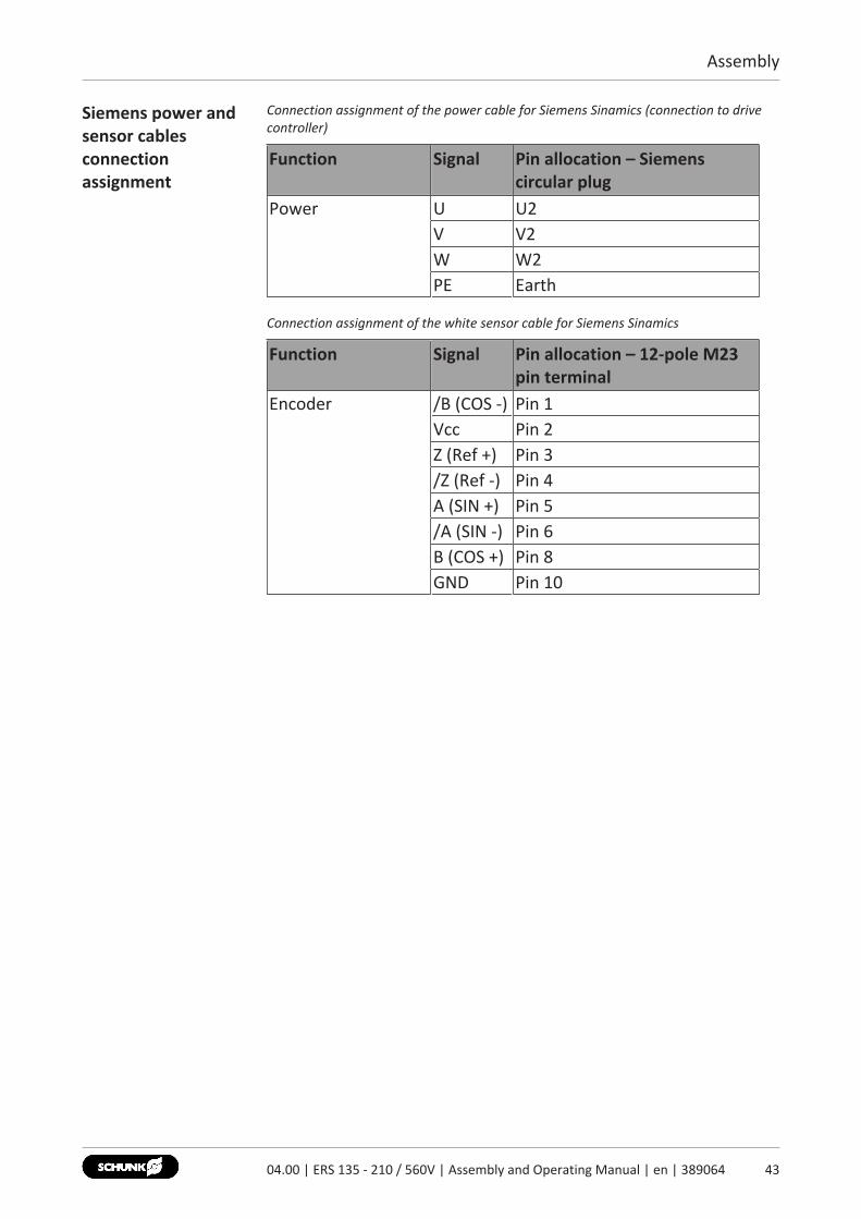
Siemens power andsensor cablesconnectionassignment
Connection assignment of the power cable for Siemens Sinamics (connection to drivecontroller)
Function Signal Pin allocation – Siemenscircular plug
Power U U2V V2W W2PE Earth
Connection assignment of the white sensor cable for Siemens Sinamics
Function Signal Pin allocation – 12-pole M23pin terminal
Encoder /B (COS -) Pin 1Vcc Pin 2Z (Ref +) Pin 3/Z (Ref -) Pin 4A (SIN +) Pin 5/A (SIN -) Pin 6B (COS +) Pin 8GND Pin 10
4304.00 | ERS 135 - 210 / 560V | Assembly and Operating Manual | en | 389064
Assembly
44 04.00 | ERS 135 - 210 / 560V | Assembly and Operating Manual | en | 389064
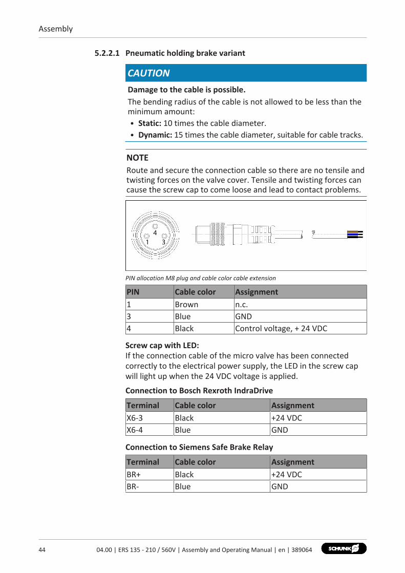
5.2.2.1 Pneumatic holding brake variant
CAUTIONDamage to the cable is possible.The bending radius of the cable is not allowed to be less than theminimum amount:• Static: 10 times the cable diameter.• Dynamic: 15 times the cable diameter, suitable for cable tracks.
NOTERoute and secure the connection cable so there are no tensile andtwisting forces on the valve cover. Tensile and twisting forces cancause the screw cap to come loose and lead to contact problems.
PIN allocation M8 plug and cable color cable extension
PIN Cable color Assignment1 Brown n.c.3 Blue GND4 Black Control voltage, + 24 VDC
Screw cap with LED:If the connection cable of the micro valve has been connectedcorrectly to the electrical power supply, the LED in the screw capwill light up when the 24 VDC voltage is applied.
Connection to Bosch Rexroth IndraDrive
Terminal Cable color AssignmentX6-3 Black +24 VDCX6-4 Blue GND
Connection to Siemens Safe Brake Relay
Terminal Cable color AssignmentBR+ Black +24 VDCBR- Blue GND
Assembly
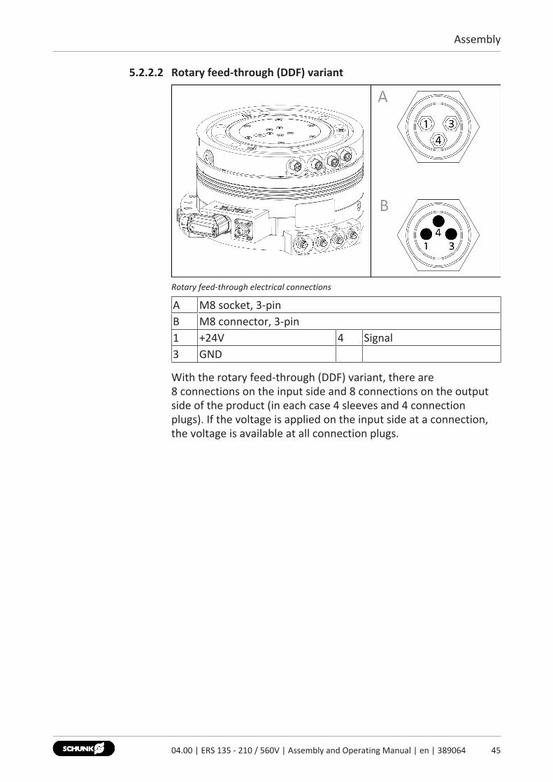
5.2.2.2 Rotary feed-through (DDF) variant
Rotary feed-through electrical connections
A M8 socket, 3-pinB M8 connector, 3-pin1 +24V 4 Signal3 GND
With the rotary feed-through (DDF) variant, there are 8 connections on the input side and 8 connections on the outputside of the product (in each case 4 sleeves and 4 connectionplugs). If the voltage is applied on the input side at a connection,the voltage is available at all connection plugs.
4504.00 | ERS 135 - 210 / 560V | Assembly and Operating Manual | en | 389064
Troubleshooting
46 04.00 | ERS 135 - 210 / 560V | Assembly and Operating Manual | en | 389064
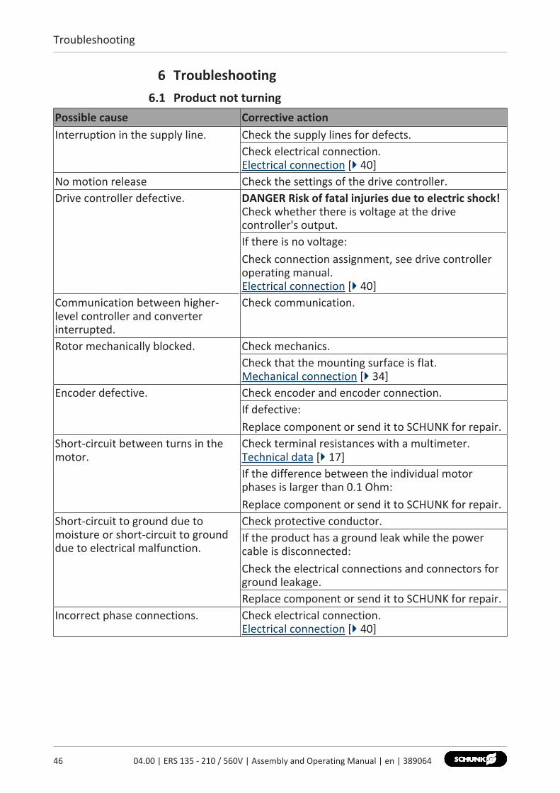
6 Troubleshooting6.1 Product not turning
Possible cause Corrective actionInterruption in the supply line. Check the supply lines for defects.
Check electrical connection.Electrical connection [} 40]
No motion release Check the settings of the drive controller.Drive controller defective. DANGER Risk of fatal injuries due to electric shock!
Check whether there is voltage at the drivecontroller's output.If there is no voltage:Check connection assignment, see drive controlleroperating manual.Electrical connection [} 40]
Communication between higher-level controller and converterinterrupted.
Check communication.
Rotor mechanically blocked. Check mechanics.Check that the mounting surface is flat.Mechanical connection [} 34]
Encoder defective. Check encoder and encoder connection.If defective:Replace component or send it to SCHUNK for repair.
Short-circuit between turns in themotor.
Check terminal resistances with a multimeter.Technical data [} 17]If the difference between the individual motorphases is larger than 0.1 Ohm:Replace component or send it to SCHUNK for repair.
Short-circuit to ground due tomoisture or short-circuit to grounddue to electrical malfunction.
Check protective conductor.If the product has a ground leak while the powercable is disconnected:Check the electrical connections and connectors forground leakage.Replace component or send it to SCHUNK for repair.
Incorrect phase connections. Check electrical connection.Electrical connection [} 40]

Troubleshooting
Possible cause Corrective actionDrive controller settings areincorrect.
Check the parameters and setting values, seeoperating manual for the drive controller.
Motor phases or encoder signalsconfused.
Check electrical connection.Electrical connection [} 40]Check the encoder signals and the shielding of thesensor cable.
6.2 Product is having control difficulties.Possible cause Corrective actionDriver controller is not optimallyadjusted.
Check the settings (direction of rotation of motorand encoder direction of counting).
6.3 Product is vibrating.Possible cause Corrective actionLoad inertia is too high. Check the dimensioning.
Reduce the load.Check the settings on the drive controller.
Drive controller is not optimallyadjusted.
Check the settings on the drive controller.
6.4 Bearing noisePossible cause Corrective actionIncorrect assembly. Check that the mounting surface is flat.
Mechanical connection [} 34]Bearing defective due to overload. Replace component or send it to SCHUNK for repair.
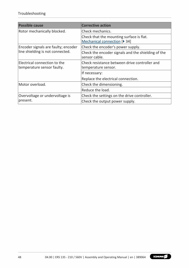
6.5 Error message for the winding temperaturePossible cause Corrective actionElectrical connection to thetemperature sensor faulty.
Check resistance between drive controller andtemperature sensor.If necessary:Replace electrical connection.
Temperature sensor defective. Check the resistance of the temperature sensor.If the resistance at room temperature is larger than630 Ohm:Replace component or send it to SCHUNK for repair.
Thermal motor overload. Reduce the load.Mount the motor on heat-conducting materials todissipate excess motor heat.
4704.00 | ERS 135 - 210 / 560V | Assembly and Operating Manual | en | 389064
Troubleshooting
48 04.00 | ERS 135 - 210 / 560V | Assembly and Operating Manual | en | 389064
Possible cause Corrective actionRotor mechanically blocked. Check mechanics.
Check that the mounting surface is flat.Mechanical connection [} 34]
Encoder signals are faulty; encoderline shielding is not connected.
Check the encoder's power supply.Check the encoder signals and the shielding of thesensor cable.
Electrical connection to thetemperature sensor faulty.
Check resistance between drive controller andtemperature sensor.If necessary:Replace the electrical connection.
Motor overload. Check the dimensioning.Reduce the load.
Overvoltage or undervoltage ispresent.
Check the settings on the drive controller.Check the output power supply.
Maintenance
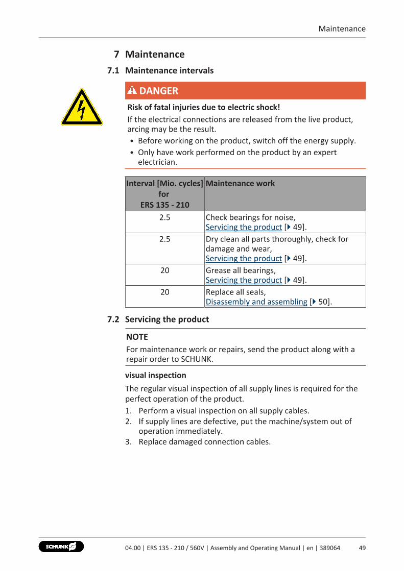
7 Maintenance7.1 Maintenance intervals
DANGERRisk of fatal injuries due to electric shock!If the electrical connections are released from the live product,arcing may be the result.• Before working on the product, switch off the energy supply.• Only have work performed on the product by an expert
electrician.
Interval [Mio. cycles]for
ERS 135 - 210
Maintenance work
2.5 Check bearings for noise,Servicing the product [} 49].
2.5 Dry clean all parts thoroughly, check fordamage and wear,Servicing the product [} 49].
20 Grease all bearings,Servicing the product [} 49].
20 Replace all seals,Disassembly and assembling [} 50].
7.2 Servicing the product
NOTEFor maintenance work or repairs, send the product along with arepair order to SCHUNK.
visual inspectionThe regular visual inspection of all supply lines is required for theperfect operation of the product.1. Perform a visual inspection on all supply cables.2. If supply lines are defective, put the machine/system out of
operation immediately.3. Replace damaged connection cables.
4904.00 | ERS 135 - 210 / 560V | Assembly and Operating Manual | en | 389064

Maintenance
50 04.00 | ERS 135 - 210 / 560V | Assembly and Operating Manual | en | 389064
Acoustic bearing inspection
Bearing noise Further procedureSmooth noise Product can continue to be operated.Rough grinding noise The motor is not set up correctly:
• Check the evenness at mountingsurfaces.Mechanical connection [} 34]
Loud and rough noise ormotor not runningsmoothly
The motor is not set up correctly:• Check the evenness at mounting
surfaces.Mechanical connection [} 34]
Bearings defective:• Replace component or send it to
SCHUNK for repair.
7.3 Disassembly and assemblingThis product must not be disassembled for maintenance.
CAUTIONMaterial damage due to improper disassembly!Incorrect works can cause damage to the mechanics and internalelectronics.• Disassembly or opening of the product is not permitted.• Only allow SCHUNK to repair the product.

Translation of original declaration of incorporation
8 Translation of original declaration of incorporationin terms of the Directive 2006/42/EG, Annex II, Part 1.B of the European Parliament and ofthe Council on machinery.Manufacturer/ Distributor
SCHUNK GmbH & Co. KG Spann- und GreiftechnikBahnhofstr. 106 – 134D-74348 Lauffen/Neckar
We hereby declare that on the date of the declaration the following partly completedmachine complied with all basic safety and health regulations found in the directive2006/42/EC of the European Parliament and of the Council on machinery. The declarationis rendered invalid if modifications are made to the product.
Product designation: Electrical turning unit with torque motor / ERS 135 - 210 /560V / electric
ID number 0310146 ... 0310224
The product also complies with LVD Directive (2014/35/EU).
Applied harmonized standards, especially:
EN ISO 12100:2010 Safety of machinery - General principles for design -Risk assessment and risk reduction
EN 60204-1: 2006 Safety of machinery – Electrical equipment of machines, Part 1:General requirements
DIN EN 61000-6-2:2011-06
Electromagnetic compatibility (EMC) - Part 6-2: Generic standards- Immunity for industrial environments
EN 61000-6-4:2007 +A1:2011
Electromagnetic compatibility (EMC) - Part 6-4: Generic standards- Emission standard for industrial environments(IEC 61000-6-4:2006 + A1:2010);
ISO 9409-1:2004-03 Manipulating industrial robots - Mechanical interfaces - Part 1: plates
The partly completed machine may not be put into operation until conformity of themachine into which the partly completed machine is to be installed with the provisions ofthe Machinery Directive (2006/42/EC) is confirmed.The manufacturer agrees to forward on demand the relevant technical documentation forthe partly completed machinery in electronic form to national authorities.The relevant technical documentation according to Annex VII, Part B, belonging to thepartly completed machinery, has been created.Person authorized to compile the technical documentation: Robert Leuthner, Address: see manufacturer's address
Lauffen/Neckar, January 2021 Dr.-Ing. Manuel Baumeister, Technology & Innovation,
Mechatronics & Sensors
5104.00 | ERS 135 - 210 / 560V | Assembly and Operating Manual | en | 389064
Translation of original declaration of incorporation
52 04.00 | ERS 135 - 210 / 560V | Assembly and Operating Manual | en | 389064
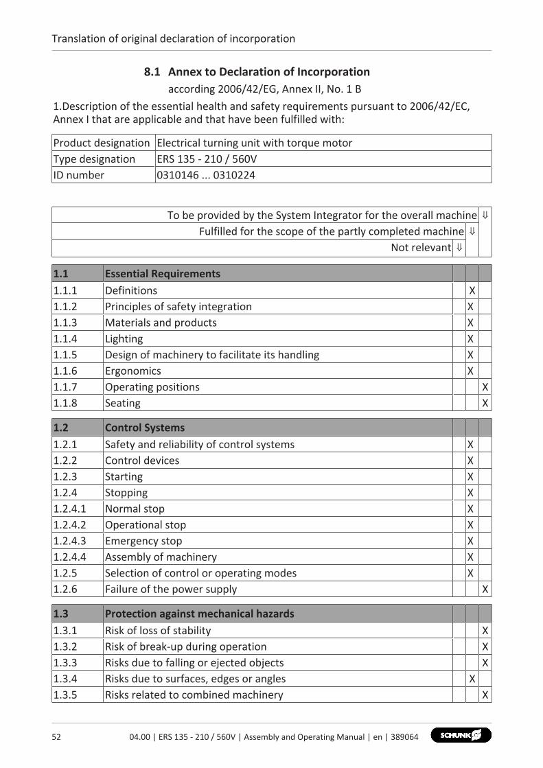
8.1 Annex to Declaration of Incorporationaccording 2006/42/EG, Annex II, No. 1 B
1.Description of the essential health and safety requirements pursuant to 2006/42/EC,Annex I that are applicable and that have been fulfilled with:
Product designation Electrical turning unit with torque motorType designation ERS 135 - 210 / 560VID number 0310146 ... 0310224
To be provided by the System Integrator for the overall machine ⇓Fulfilled for the scope of the partly completed machine ⇓
Not relevant ⇓
1.1 Essential Requirements1.1.1 Definitions X1.1.2 Principles of safety integration X1.1.3 Materials and products X1.1.4 Lighting X1.1.5 Design of machinery to facilitate its handling X1.1.6 Ergonomics X1.1.7 Operating positions X1.1.8 Seating X
1.2 Control Systems1.2.1 Safety and reliability of control systems X1.2.2 Control devices X1.2.3 Starting X1.2.4 Stopping X1.2.4.1 Normal stop X1.2.4.2 Operational stop X1.2.4.3 Emergency stop X1.2.4.4 Assembly of machinery X1.2.5 Selection of control or operating modes X1.2.6 Failure of the power supply X
1.3 Protection against mechanical hazards1.3.1 Risk of loss of stability X1.3.2 Risk of break-up during operation X1.3.3 Risks due to falling or ejected objects X1.3.4 Risks due to surfaces, edges or angles X1.3.5 Risks related to combined machinery X

Translation of original declaration of incorporation
1.3 Protection against mechanical hazards1.3.6 Risks related to variations in operating conditions X1.3.7 Risks related to moving parts X1.3.8 Choice of protection against risks arising from moving parts1.3.8.1 Moving transmission parts X1.3.8.2 Moving parts involved in the process X1.3.9 Risks of uncontrolled movements X
1.4 Required characteristics of guards and protective devices1.4.1 General requirements X1.4.2 Special requirements for guards X1.4.2.1 Fixed guards X1.4.2.2 Interlocking movable guards X1.4.2.3 Adjustable guards restricting access X1.4.3 Special requirements for protective devices X
1.5 Risks due to other hazards1.5.1 Electricity supply X1.5.2 Static electricity X1.5.3 Energy supply other than electricity X1.5.4 Errors of fitting X1.5.5 Extreme temperatures X1.45.6 Fire X1.5.7 Explosion X1.5.8 Noise X1.5.9 Vibrations X1.5.10 Radiation X1.5.11 External radiation X1.5.12 Laser radiation X1.5.13 Emissions of hazardous materials and substances X1.5.14 Risk of being trapped in a machine X1.5.15 Risk of slipping, tripping or falling X1.5.16 Lightning X
1.6 Maintenance1.6.1 Machinery maintenance X1.6.2 Access to operating positions and servicing points X1.6.3 Isolation of energy sources X1.6.4 Operator intervention X1.6.5 Cleaning of internal parts X
5304.00 | ERS 135 - 210 / 560V | Assembly and Operating Manual | en | 389064

Translation of original declaration of incorporation
54 04.00 | ERS 135 - 210 / 560V | Assembly and Operating Manual | en | 389064
1.7 Information1.7.1 Information and warnings on the machinery X1.7.1.1 Information and information devices X1.7.1.2 Warning devices X1.7.2 Warning of residual risks X X1.7.3 Marking of machinery X1.7.4 Instructions X1.7.4.1 General principles for the drafting of instructions X1.7.4.2 Contents of the instructions X1.7.4.3 Sales literature X
The classification from Annex 1 is to be supplemented from hereforward.
2 Supplementary essential health and safety requirements for certaincategories of machinery
X
2.1 Foodstuffs machinery and machinery for cosmetics or pharmaceuticalproducts
X
2.2 Portable hand-held and/or guided machinery X2.2.1 Portable fixing and other impact machinery X2.3 Machinery for working wood and material with similar physical
characteristicsX
3 Supplementary essential health and safety requirements to offsethazards due to the mobility of machinery
X
4 Supplementary essential health and safety requirements to offsethazards due to lifting operations
X
5 Supplementary essential health and safety requirements for machineryintended for underground work
X
6 Supplementary essential health and safety requirements for machinerypresenting particular hazards due to the lifting of persons
X X

Translation of Original Operating Manual
SCHUNK GmbH & Co. KGSpann- und GreiftechnikBahnhofstr. 106 – 134D-74348 Lauffen/NeckarTel. +49-7133-103-0Fax [email protected]
Folgen Sie uns I Follow us01
-202
1
© 2
021
SCHU
NK
GmbH
& C
o. K
G
04.0
0 |
ERS
| As
sem
bly
and
Ope
ratin
g M
anua
l | e
n |
3890
64