assembly and operating instructions for suspended platform ... · pdf file2. always use gloves...
TRANSCRIPT
760065-C-0814
Assembly and operating instructions for
suspended platform system Modular suspended work platform in assembled length s from 2m to 19m
Conform to UL code
Trained person must always supervise the installation procedure. Local safety regulations and codes must be understood and followed.
All persons operating this equipment must read and completely understand this manual. Any operation in violation of these instructions is at the operator’s own risk.
Please be sure to consult with your Altrex supplier on factory approval for any configurations not listed in any tables of this manual.
Keep this manual with the equipment at all times! This document will supersede previous versions.
Copyright 2014 by ALTREX B.V. – Zwolle / The Nether lands
Date: 15-08-2014

Art. 760065-C-0814 2/19
Index
Chapter Page
1 SAFETY GUIDELINES TO PREVENT ACCIDENTS............................................................ 3
2 CODES OF SAFE PRACTICE............................................................................................. 4
2.1 INSTALLATION........................................................................................................................................................................................4 2.2 USE .........................................................................................................................................................................................................4 2.3 MAINTENANCE ......................................................................................................................................................................................4
3 DO’S & DON'T’S............................................................................................................... 5
3.1 GENERAL ................................................................................................................................................................................................5 3.2 END STIRRUP..........................................................................................................................................................................................5 3.3 WALK THROUGH STIRRUP .....................................................................................................................................................................6 3.4 QUICK-PINS............................................................................................................................................................................................6 3.5 HOIST .....................................................................................................................................................................................................6 3.6 GUARD RAIL ...........................................................................................................................................................................................7 3.7 CANTILEVERED SECTIONS......................................................................................................................................................................7
4 IDENTIFICATION OF SUSPENDED PLATFORM PARTS.................................................. 9
5 DIMENSIONS OF SUSPENDED PLATFORM SYSTEM................................................... 10
6 LOAD CAPACITY AND CONFIGURATION TABLES ...................................................... 11
7 ASSEMBLY INSTRUCTIONS .......................................................................................... 12
7.1 TEMPORARY SUSPENDED PLATFORM FOR USE WITH END STIRRUPS .............................................................................................. 12 7.2 TEMPORARY SUSPENDED PLATFORM FOR USE WITH WALK THROUGH STIRRUPS ......................................................................... 13 7.3 TEMPORARY SUSPENDED PLATFORM FOR USE WITH WALK THROUGH FRAMES ........................................................................... 14
8 CODE OF SAFE PRACTICES FOR SUSPENDED POWERED SCAFFOLDS...................... 15

Art. 760065-C-0814 3/19
1 Safety guidelines to prevent accidents Severe injury or even death can result from imprope r assembly or improper use of this suspended platform system. • Do not use the suspended platform system unless:
• You have read and understood the Scaffold Industry Association’s suspended Platforms Codes of safe Practice (see chapter 8).
• You are wearing properly rigged fall arrest equipment. • You comply with the platform assembly instructions and safety information.
• Be aware that the suspended platform is only one component of a suspended scaffold system.
You must comply with each manufacturer's / supplier's instructions and all local, state and national safety standards and regulations. Ask your local supplier.
• You must read and understand this manual before using the suspended platform system. • Do not make complete or incomplete copies of this manual by yourself. • Stop using the suspended platform system immediately if any of the system components do not
operate properly or if any of the system components are damaged – call your supervisor for help.
• Only use original suspended platform system components of Altrex.
• Only trained personnel shall assemble and use this suspended platform. • Use only legal copies of the latest version of this manual. The legal and latest version of the
"Assembly & Operating Instructions for suspended platform system" are, on request, available at the supplier of your suspended platform system. Use only the complete document; “Assembly and operating instructions for suspended platform system”.
• This document is restricted to the suspended platform manufactured by Altrex. • Be aware these safety guidelines are not all inclusive. Proper training for all individuals erecting,
installing and using this equipment is mandatory. • Do not assemble or use platform unless all components are present and in use. • If (any) part of the suspended platform system is exposed to excessive heat (as in the case of a
fire), remove this part from service and destroy it due to loss of structural strength. • Additional copies of warning labels are available should the original labeling become damaged,
obscured or removed. Contact your Altrex platform supplier. • This document must be kept on this suspended platform system.
Art. 760065-C-0814 4/19
2 Codes of safe practice All suspended platform system must be assembled as detailed in chapter 6 “load capacity and configuration tables”. This is the manner in which the platforms were tested and classified by UL. Before every installation of the equipment, the operator(s) should read and understand fully the contents of this manual. Serious injuries to personnel may result if the instructions are not followed. Before using the equipment, the operator(s) must check the suspension system to ensure the stability at all times. Use only Altrex equipment. If otherwise, ask your supplier for a declaration permission. 2.1 Installation 1. Act according to this document. 2. Always use gloves when assembling and dismantling the suspended platform to avoid injuries. 2.2 Use 1. Stop using the suspended platform system immediately if any of the components do not operate
properly or other circumstances may jeopardize safety – call your supervisor for assistance. The equipment as described in this manual may not be used for operation in silo's, shaft and underground access. Special precautions are required for these specific applications.
2. Before and after using, check all parts for proper function and damage to component parts. Do not
use a damaged or improperly functioning part of the suspended platform system. 3. In case the area below the platform system is open to the public, preventive measures have to be
taken to safeguard the people below. (E.g. barriers, roof protected walkways, etc.)
3. Only authorized and trained persons shall operate this equipment. 4. An area must be available to allow the operator(s) to get on and off the platform safely.
5. The operator(s) shall check for obstructions along the travel of the platform.
6. After the (daily) work is finished the operator(s) shall bring the equipment in the "out of service
position", switch off and isolate from the main power supply source.
7. The equipment may not be used when wind speed is more than 25 mph.
8. For physical, environment and operating conditions of the electric equipment, check the instruction manual of your hoisting manufacturer.
2.3 Maintenance 1. After installation, daily and after every emergency-stop, the operator must carry out a check and
make sure that the equipment is in perfect working condition. 2. Use only original spare parts.
Art. 760065-C-0814 5/19
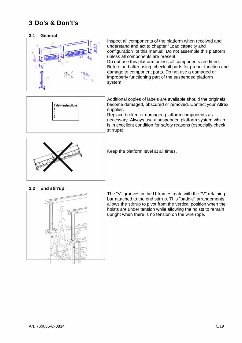
3 Do’s & Don't’s 3.1 General
Inspect all components of the platform when received and understand and act to chapter “Load capacity and configuration” of this manual. Do not assemble this platform unless all components are present. Do not use this platform unless all components are fitted. Before and after using, check all parts for proper function and damage to component parts. Do not use a damaged or improperly functioning part of the suspended platform system.
Safety instructions 1
2
3
Additional copies of labels are available should the originals become damaged, obscured or removed. Contact your Altrex supplier. Replace broken or damaged platform components as necessary. Always use a suspended platform system which is in excellent condition for safety reasons (especially check stirrups).
Keep the platform level at all times.
3.2 End stirrup
The "V" grooves in the U-frames mate with the "V" retaining bar attached to the end stirrup. This "saddle" arrangements allows the stirrup to pivot from the vertical position when the hoists are under tension while allowing the hoists to remain upright when there is no tension on the wire rope.
Art. 760065-C-0814 6/19
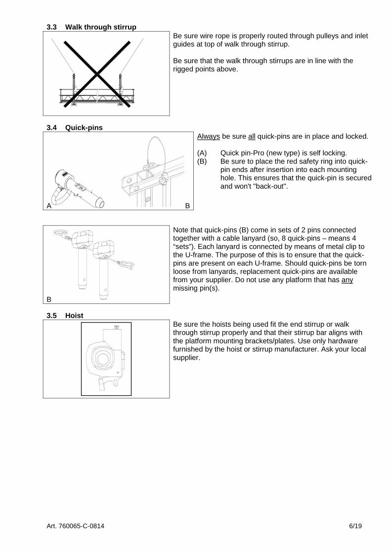
3.3 Walk through stirrup
Be sure wire rope is properly routed through pulleys and inlet guides at top of walk through stirrup. Be sure that the walk through stirrups are in line with the rigged points above.
3.4 Quick-pins
A
B
Always be sure all quick-pins are in place and locked. (A) Quick pin-Pro (new type) is self locking. (B) Be sure to place the red safety ring into quick- pin ends after insertion into each mounting hole. This ensures that the quick-pin is secured and won't "back-out".
B
Note that quick-pins (B) come in sets of 2 pins connected together with a cable lanyard (so, 8 quick-pins – means 4 “sets”). Each lanyard is connected by means of metal clip to the U-frame. The purpose of this is to ensure that the quick-pins are present on each U-frame. Should quick-pins be torn loose from lanyards, replacement quick-pins are available from your supplier. Do not use any platform that has any missing pin(s).
3.5 Hoist
Be sure the hoists being used fit the end stirrup or walk through stirrup properly and that their stirrup bar aligns with the platform mounting brackets/plates. Use only hardware furnished by the hoist or stirrup manufacturer. Ask your local supplier.

Art. 760065-C-0814 7/19
3.6 Guard rail
Guard rails must be extended and used at all times. Note, adjustments available in guard rail posts. Height must not be less than 42" above platform deck.
3.7 Cantilevered sections
When using cantilevered sections, please read and act to chapter “Load capacity and configurations tables” for the UL-listed configurations. Note that cantilevered sections must balance (be equal in length on both sides). Please be sure to consult with your Altrex supplier on factory approval for any configurations not listed in the tables as mentioned in chapter 6; ”Load capacity and configuration tables.”

Art. 760065-C-0814 8/19
Do not use acids (such as muriac or hydrochloric) or other corrosive substances that can effect the strength of aluminum. Should such substances come in contact with this platform, they must be immediately cleaned from the equipment and neutralized as quickly as possible. Remove all platform sections suspected or subjected to corrosive attack from service.
Do not use metal platforms near any electrical current. Contact the local electrical utility for recommendations. Danger – metal conducts electricity. Maintain a minimum safe distance of at least 10 ft. (3m). Consult the power company to shut off power or insulate/relocate the line if working closer than 10 ft (3m).
Do not use the suspended platform system if the decking surface is damaged or has deteriorated. Do not paint
Keep platform deck free from dirt and debris (especially oil or grease, which can cause a slipping hazard) and keep the platform level at all times. Do not permit slippery material to accumulate on the platform deck. Do not allow instable objects, such as boxes / loose bricks / tools and debris to accumulate on the platform deck.
Do not modify this platform in any way. This platform has been designed, engineered, manufactured and tested to exacting standards.
Do not apply impact loads to platform (e.g. dropping anything on the deck of the platform), or any other part.
Do not overload or extend platform's total length or loading (refer to chapter 6 “Load capacity and configuration tables”). Be sure to evenly distribute weight (loading) on platform and to roof rig accordingly (adequate counter weight and tie backs).
Do not use the suspended platform system as an elevator. Do not use a ladder or other device to gain greater heights.
Do not weld anything to the component parts of the suspended platform system.
Do not repair components without permission of the manufacturer.
Art. 760065-C-0814 9/19
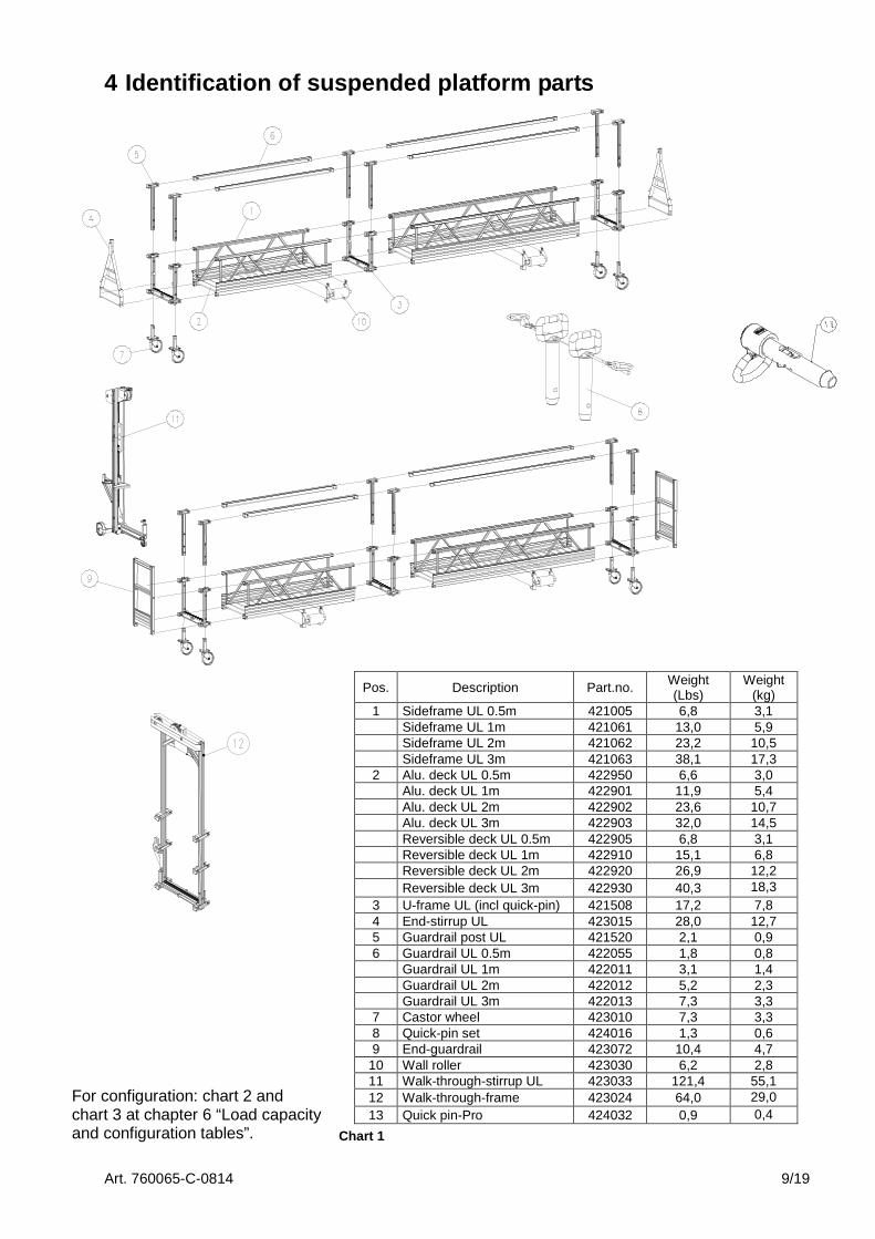
4 Identification of suspended platform parts
Pos. Description Part.no. Weight (Lbs)
Weight (kg)
1 Sideframe UL 0.5m 421005 6,8 3,1 Sideframe UL 1m 421061 13,0 5,9 Sideframe UL 2m 421062 23,2 10,5 Sideframe UL 3m 421063 38,1 17,3
2 Alu. deck UL 0.5m 422950 6,6 3,0 Alu. deck UL 1m 422901 11,9 5,4 Alu. deck UL 2m 422902 23,6 10,7 Alu. deck UL 3m 422903 32,0 14,5 Reversible deck UL 0.5m 422905 6,8 3,1 Reversible deck UL 1m 422910 15,1 6,8 Reversible deck UL 2m 422920 26,9 12,2 Reversible deck UL 3m 422930 40,3 18,3
3 U-frame UL (incl quick-pin) 421508 17,2 7,8 4 End-stirrup UL 423015 28,0 12,7 5 Guardrail post UL 421520 2,1 0,9 6 Guardrail UL 0.5m 422055 1,8 0,8 Guardrail UL 1m 422011 3,1 1,4 Guardrail UL 2m 422012 5,2 2,3 Guardrail UL 3m 422013 7,3 3,3
7 Castor wheel 423010 7,3 3,3 8 Quick-pin set 424016 1,3 0,6 9 End-guardrail 423072 10,4 4,7
10 Wall roller 423030 6,2 2,8 11 Walk-through-stirrup UL 423033 121,4 55,1 12 Walk-through-frame 423024 64,0 29,0 13 Quick pin-Pro 424032 0,9 0,4
For configuration: chart 2 and chart 3 at chapter 6 “Load capacity and configuration tables”. Chart 1
Art. 760065-C-0814 10/19
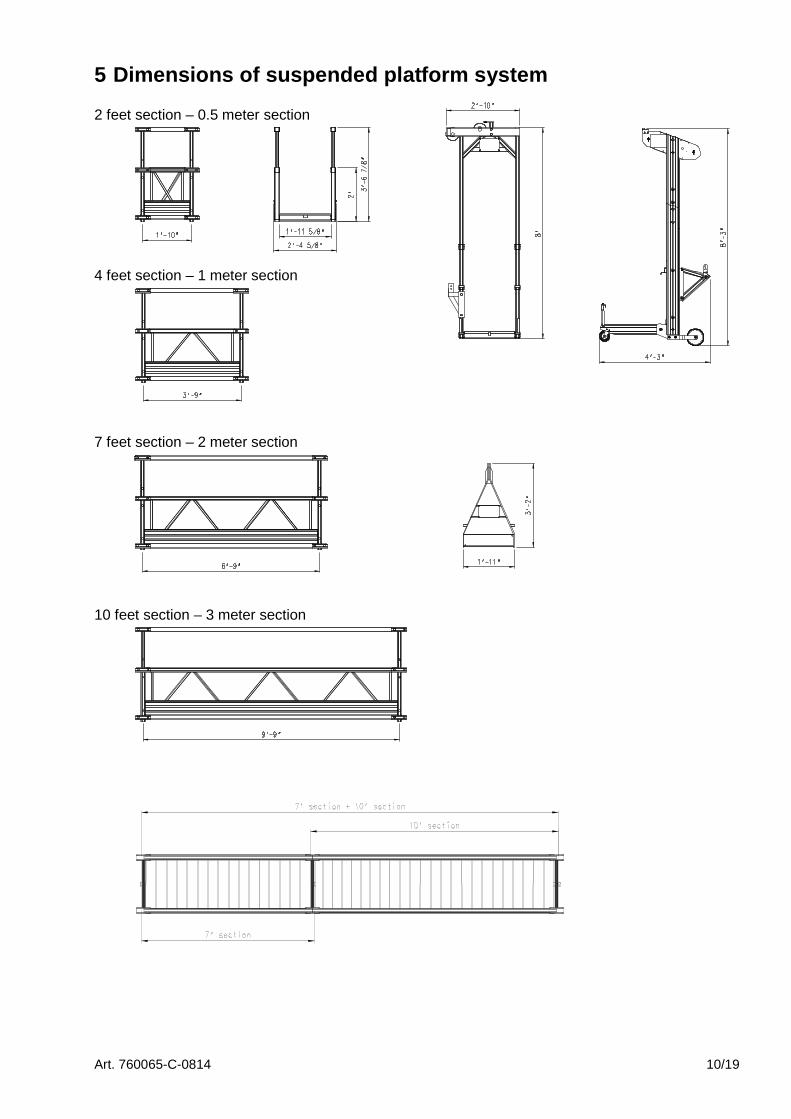
5 Dimensions of suspended platform system 2 feet section – 0.5 meter section 4 feet section – 1 meter section 7 feet section – 2 meter section 10 feet section – 3 meter section
Art. 760065-C-0814 11/19
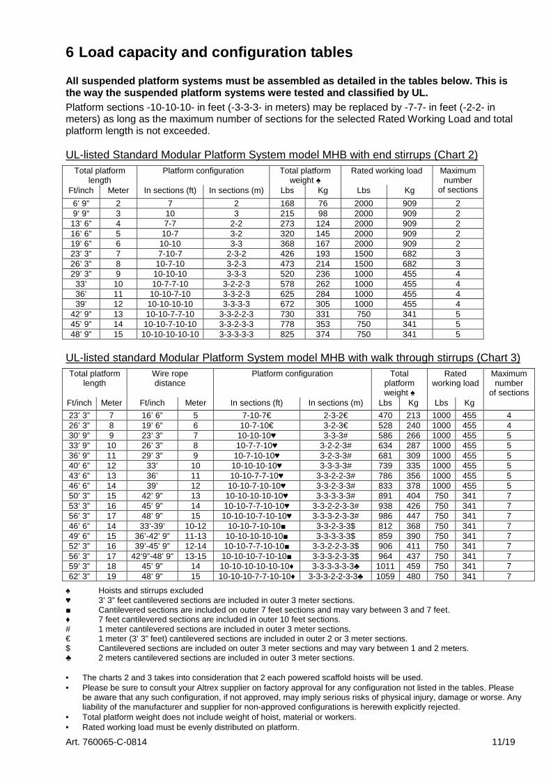
6 Load capacity and configuration tables All suspended platform systems must be assembled as detailed in the tables below. This is the way the suspended platform systems were tested and classified by UL. Platform sections -10-10-10- in feet (-3-3-3- in meters) may be replaced by -7-7- in feet (-2-2- in meters) as long as the maximum number of sections for the selected Rated Working Load and total platform length is not exceeded. UL-listed Standard Modular Platform System model MHB with end stirrups (Chart 2)
Total platform length
Platform configuration Total platform weight ♠
Rated working load
Ft/inch Meter In sections (ft) In sections (m) Lbs Kg Lbs Kg
Maximum number
of sections
6’ 9” 2 7 2 168 76 2000 909 2 9’ 9” 3 10 3 215 98 2000 909 2
13’ 6” 4 7-7 2-2 273 124 2000 909 2 16’ 6” 5 10-7 3-2 320 145 2000 909 2 19’ 6” 6 10-10 3-3 368 167 2000 909 2 23’ 3” 7 7-10-7 2-3-2 426 193 1500 682 3 26’ 3” 8 10-7-10 3-2-3 473 214 1500 682 3 29’ 3” 9 10-10-10 3-3-3 520 236 1000 455 4
33’ 10 10-7-7-10 3-2-2-3 578 262 1000 455 4 36’ 11 10-10-7-10 3-3-2-3 625 284 1000 455 4 39’ 12 10-10-10-10 3-3-3-3 672 305 1000 455 4
42’ 9” 13 10-10-7-7-10 3-3-2-2-3 730 331 750 341 5 45’ 9” 14 10-10-7-10-10 3-3-2-3-3 778 353 750 341 5 48’ 9” 15 10-10-10-10-10 3-3-3-3-3 825 374 750 341 5
UL-listed standard Modular Platform System model MHB with walk through stirrups (Chart 3)
Total platform length
Wire rope distance
Platform configuration Total platform weight ♠
Rated working load
Ft/inch Meter Ft/inch Meter In sections (ft) In sections (m) Lbs Kg Lbs Kg
Maximum number
of sections
23’ 3” 7 16’ 6” 5 7-10-7€ 2-3-2€ 470 213 1000 455 4 26’ 3” 8 19’ 6” 6 10-7-10€ 3-2-3€ 528 240 1000 455 4 30’ 9” 9 23’ 3” 7 10-10-10♥ 3-3-3# 586 266 1000 455 5 33’ 9” 10 26’ 3” 8 10-7-7-10♥ 3-2-2-3# 634 287 1000 455 5 36’ 9” 11 29’ 3” 9 10-7-10-10♥ 3-2-3-3# 681 309 1000 455 5 40’ 6” 12 33’ 10 10-10-10-10♥ 3-3-3-3# 739 335 1000 455 5 43’ 6” 13 36’ 11 10-10-7-7-10♥ 3-3-2-2-3# 786 356 1000 455 5 46’ 6” 14 39’ 12 10-10-7-10-10♥ 3-3-2-3-3# 833 378 1000 455 5 50’ 3” 15 42’ 9” 13 10-10-10-10-10♥ 3-3-3-3-3# 891 404 750 341 7 53’ 3” 16 45’ 9” 14 10-10-7-7-10-10♥ 3-3-2-2-3-3# 938 426 750 341 7 56’ 3” 17 48’ 9” 15 10-10-10-7-10-10♥ 3-3-3-2-3-3# 986 447 750 341 7 46’ 6” 14 33’-39’ 10-12 10-10-7-10-10■ 3-3-2-3-3$ 812 368 750 341 7 49’ 6” 15 36’-42’ 9” 11-13 10-10-10-10-10■ 3-3-3-3-3$ 859 390 750 341 7 52’ 3” 16 39’-45’ 9” 12-14 10-10-7-7-10-10■ 3-3-2-2-3-3$ 906 411 750 341 7 56’ 3” 17 42’9”-48’ 9” 13-15 10-10-10-7-10-10■ 3-3-3-2-3-3$ 964 437 750 341 7 59’ 3” 18 45’ 9” 14 10-10-10-10-10-10♦ 3-3-3-3-3-3♣ 1011 459 750 341 7 62’ 3” 19 48’ 9” 15 10-10-10-7-7-10-10♦ 3-3-3-2-2-3-3♣ 1059 480 750 341 7
♠ Hoists and stirrups excluded ♥ 3’ 3” feet cantilevered sections are included in outer 3 meter sections. ■ Cantilevered sections are included on outer 7 feet sections and may vary between 3 and 7 feet. ♦ 7 feet cantilevered sections are included in outer 10 feet sections. # 1 meter cantilevered sections are included in outer 3 meter sections. € 1 meter (3’ 3” feet) cantilevered sections are included in outer 2 or 3 meter sections. $ Cantilevered sections are included on outer 3 meter sections and may vary between 1 and 2 meters. ♣ 2 meters cantilevered sections are included in outer 3 meter sections. • The charts 2 and 3 takes into consideration that 2 each powered scaffold hoists will be used. • Please be sure to consult your Altrex supplier on factory approval for any configuration not listed in the tables. Please
be aware that any such configuration, if not approved, may imply serious risks of physical injury, damage or worse. Any liability of the manufacturer and supplier for non-approved configurations is herewith explicitly rejected.
• Total platform weight does not include weight of hoist, material or workers. • Rated working load must be evenly distributed on platform.
Art. 760065-C-0814 12/19
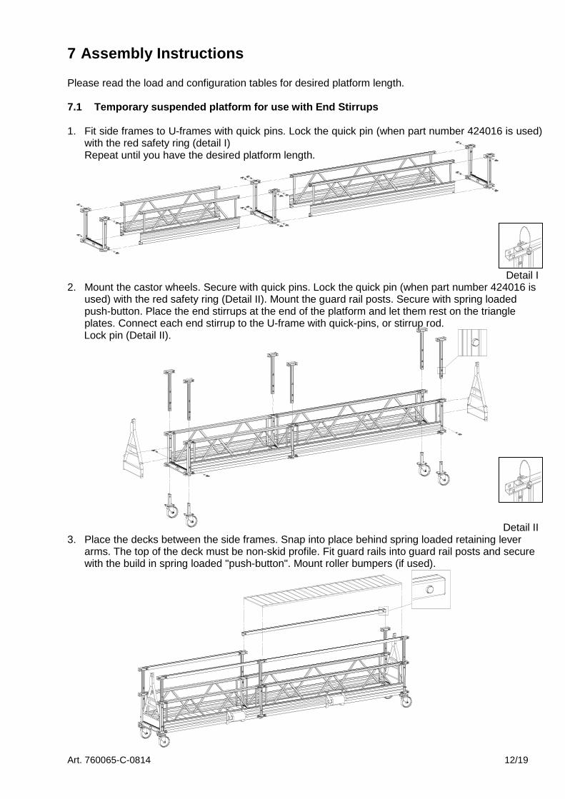
7 Assembly Instructions Please read the load and configuration tables for desired platform length. 7.1 Temporary suspended platform for use with End S tirrups
1. Fit side frames to U-frames with quick pins. Lock the quick pin (when part number 424016 is used)
with the red safety ring (detail I) Repeat until you have the desired platform length.
Detail I
2. Mount the castor wheels. Secure with quick pins. Lock the quick pin (when part number 424016 is used) with the red safety ring (Detail II). Mount the guard rail posts. Secure with spring loaded push-button. Place the end stirrups at the end of the platform and let them rest on the triangle plates. Connect each end stirrup to the U-frame with quick-pins, or stirrup rod.
Lock pin (Detail II).
Detail II 3. Place the decks between the side frames. Snap into place behind spring loaded retaining lever
arms. The top of the deck must be non-skid profile. Fit guard rails into guard rail posts and secure with the build in spring loaded "push-button". Mount roller bumpers (if used).

Art. 760065-C-0814 13/19
7.2 Temporary suspended platform for use with Walk Through Stirrups
1. Fit side frames to U-frames with quick pins. Lock the quick pin (when part number 424016 is used) with the red safety ring (detail I). Repeat until you have the desired platform length.
Detail I 2. Mount the castor wheels. Secure with quick pins. Lock the quick pin (when part number 424016 is
used) with the red safety ring (Detail II). Mount the guard rail posts. Secure with spring loaded push-button. Connect each guard rail post to the U-frame with quick-pins. Lock pin (Detail II).
Detail II 3. Place the decks between the side frames. Snap into place behind spring loaded retaining lever
arms. The top of the deck must be non-skid profile. Read “manual walk through stirrup”. This manual does not contain the “manual walk through stirrup”. Mount the walk through stirrups in required position. So that the cantilevered sections are balanced (see “Cantilevered sections”) and the walk through stirrups align with the rigging points above – use hardware provided. Mount guard rails and secure with spring loaded push-button. Mount roller bumpers (if used).

Art. 760065-C-0814 14/19
7.3 Temporary suspended platform for use with Walk Through Frames A walk through frame can be placed at the end of the suspended platform. See chapter 6 “load capacity and configuration tables” with end-stirrup. Use always two Walk Through Frames. Secure with quick-pins. Lock the quick pin. See chapter 7.1 “assembly instruction for temporary suspended platform for use with end stirrup”. A Walk Through Frame can be placed at the position of a Walk Through Stirrup. See chapter 6 “load capacity and configuration tables” with walk through stirrup. Use always two Walk Through Frames. Secure with quick-pins. Lock the quick pin. See chapter 7.2 “assembly instruction for temporary suspended platform for use with walk through stirrup”.

Art. 760065-C-0814 15/19
8 Code of safe Practices for Suspended Powered Scaf folds It shall be the responsibility of all users to read and comply with the following common sense guidelines which are designed to promote safety in the erecting, dismantling and use of Suspended Powered Scaffolds. These guidelines do not purport to be all-inclusive nor to supplant or replace other additional safety and precautionary measures to cover usual or unusual conditions. If the guidelines in any way conflict with any state, local, provincial, federal of other government statute or regulation, said statute or regulation shall supersede these guidelines and it shall be the responsibility of each user to comply therewith. I. GENERAL GUIDELINES
A. POST THESE SAFETY GUIDELINES in a conspicuous place and be sure that all persons who erect, use, locate, or dismantle suspended scaffold systems are fully aware of them and also use them in tool box safety meetings.
B. FOLLOW ALL EQUIPMENT MANUFACTURERERS’ RECOMMENDATIONS as well as all state, local and federal codes, ordinances and regulations relating to suspended powered scaffolding.
C. SURVEY THE JOBSITE. A survey shall bee made of the jobsite by a competent person for hazards such as exposed electrical wires, obstructions that could overload or tip the suspended powered scaffold when it is raised or lowered, unguarded roof edges or openings, inadequate or missing tiebacks. Those conditions should be corrected before installing or using suspended powered scaffold systems.
D. INSPECT ALL EQUIPMENT BEFORE EACH USE. Never use any equipment that is damaged of defective in any way. Mark it or tag it as damaged or defective equipment and remove it from the jobsite.
E. ERECT AND DISMANTLE SUSPENDED POWERED SCAFFOLD EQUIPMENT in accordance with design and/or manufacturer’s recommendations.
F. DO NOT ERECT, DISMANTLE, OR ALTER SUSPENDED POWERED SCAFFOLD SYSTEMS unless under the supervision of a competent person.
G. DO NOT ABUSE OR MISUSE SUSPENDED POWERED SCAFFOLD EQUIPMENT. Never overload platforms or hoists.
H. ERECTED SUSPENDED POWERED SCAFFOLDS SHOULD BE CONTINUOUSLY INSPECTED by the user to ensure they are maintained in a safe condition. Report any unsafe condition to your supervisor.
I. NEVER TAKE CHANCES! IF IN DOUBT REGARDING THE SAFETY OR USE OF SUSPENDED SCAFFOLDS, CONSULT YOUR SCAFFOLD SUPPLIER.
J. NEVER USE SUSPENDED SCAFFOLD EQUIPMENT FOR PURPOSE OR IN WAYS FOR WHICH IT WAS NOT INTENDED.
K. CARE SHOULD BE TAKEN WHEN OPERATING AND STORING EQUIPMENT DURING WINDY CONDITIONS.
L. SUSPENDED POWERED SCAFFOLD SYSTEMS should be installed and used in accordance with the manufacturer’s recommended procedures. Do not alter components in the field.
M. SUSPENDED POWERED PLATFORMS MUST NEVER BE OPERATED NEAR LIVE POWER LINES unless proper precautions are taken. Consult the power service company for advice.
N. ALWAYS ATTACH FALL ARREST EQUIPMENT when working on suspended powered scaffolds.
O. DO NOT WORK ON OR INSTALL SUSPENDED POWERED SCAFFOLDS if your physical condition is such that you feel dizzy or unsteady in any way.
P. DO NOT WORK ON SUSPENDED POWERED SCAFFOLDS when under the influence of alcohol or illegal drugs.

Art. 760065-C-0814 16/19
8 Code of safe Practices for Suspended Powered Scaf folds (Continued)
II. GUIDELINES FOR ERECTION AND USE OF SUSPENDED SCAFFOLD SYSTEM
A. RIGGING: 1. WEAR FALL PREVENTION
EQUIPMENT when rigging on exposed roofs or floors.
2. ROOF HOOKS, PARAPET CLAMPS, OUTRIGGER BEAMS, OR OTHER SUPPORTING DEVICES must be capable of supporting the hoist machine rated load with a safety factor of 4.
3. VERIFY THAT THE BUILDING OR STRUCTURE WILL SUPPORT the suspended loads with a factor of safety of 4.
4. ALL OVERHEAD RIGGING must be secured from movement in any direction.
5. COUNTERWEIGHTS USED WITH OUTRIGGER BEAMS must be of a rigid material and must be secured to the beam to prevent accidental displacement.
6. OUTRIGGER BEAMS THAT DO NOT USE COUNTERWEIGHTS must be installed and secured on the roof structure with devices specifically designed for that purpose. Direct connections shall be evaluated by a competent person.
7. TIE BACK ALL TRANSPORTABLE
RIGGING DEVICES. Tiebacks shall be equivalent in strength to suspension ropes.
8. INSTALL TIEBACKS AT RIGHT ANGLES TO THE FACE OF THE BUILDING and secure, without slack, to a structurally sound portion of the structure, capable of supporting the hoisting machine rated load with a safety factor of 4. IN THE EVENT TIEBACKS CANNOT BE INSTALLED AT RIGHT ANGLES, two tiebacks at opposing angles must be used to prevent movement.
9. DIRECTLY UNDER THEIR SUSPENSION POINTS.
10. RIG AND USE HOISTING MACHINES DIRECTLY UNDER THEIR SUSPENSION POINT supporting the hoisting machine rated load with a safety factor of 4. IN THE EVENT TIEBACKS CANNOT BE INSTALLED AT RIGHT ANGLES, two tiebacks at opposing angles must be used to prevent movement.
11. RIG AND USE HOISTING MACHINES DIRECTLY UNDER THEIR SUSPENSION POINTS.

Art. 760065-C-0814 17/19
8 Code of safe Practices for Suspended Powered Scaf folds (Continued)
B. WIRE ROPE AND HARDWARE
1. USE ONLY WIRE ROPE AND ATTACHMENTS as specified by the hoisting machine manufacturer.
2. ASSURE THAT WIRE ROPE IS LONG ENOUGH to reach to the lowest possible landing.
3. CLEAN AND LUBRICATE WIRE ROPE in accordance with the wire rope manufacturer’s instructions.
4. HANDLE WIRE ROPE WITH CARE. 5. COIL AND UNCOIL WIRE ROPE in
accordance with the wire rope manufacturer’s instructions in order to avoid kinks of damage.
6. TIGHTEN WIRE ROPE CLAMPS in accordance with the clamp manufacturer’s instructions.
7. DO NOT USE WIRE ROPE THAT IS KINKED, BIRDCAGED, CORRODED, UNDERSIZED, OR DAMAGED IN ANY WAY. Do not expose wire rope to fire, undue heat, corrosive atmosphere, electricity, chemicals, or damaged by tool handling.
8. USE THIMBLES AND SHACKLES AT ALL WIRE ROPE SUSPENSION TERMINATIONS.
9. USE J-TYPE CLAMPS OR SWAGED
FITTINGS. Do not use U-bolts. Retighten J-Clamps under load and retighten daily.
10. WIRE ROPES USED WITH TRACTION HOISTS MUST HAVE PREPARED ENDS. Follow manufacturer’s recommendations.
C. POWER SUPPLY
1. GROUND ALL ELECTRICAL POWER SOURCES AND POWER CORD CONNECTIONS and protect them with circuit breakers.
2. USE POWER CORDS OF THE PROPER WIRE SIZE THAT ARE LONG ENOUGH for the job.
3. POWER CORD CONNECTIONS MUST BE RESTRAINED to prevent their separation.
4. USE STRAIN RELIEF DEVICES TO ATTACH POWER CORDS TO THE SUSPENDED SCAFFOLD to prevent their separation.
5. PROTECT POWER CORDS AT SHARP EDGES.
6. USE GFI WITH TOWER TOOLS.
Art. 760065-C-0814 18/19
8 Code of safe Practices for Suspended Powered Scaf folds (Continued)
D. FALL ARREST EQUIPMENT
1. EACH PERSON ON A SUSPENDED POWERED SCAFFOLD must be attached to a separate fall arrest system unless the installation was specifically designed not to require one.
2. EACH LIFELINE MUST BE FASTENED to a separate anchorage capable of holding a minimum of 5000 pounds.
3. DO NOT WRAP LIFELINES AROUND STRUCTURAL MEMBERS unless lifelines are protected and a suitable anchorage connections is used.
4. PROTECT LIFELINES AT SHARP CORNERS to prevent chafing.
5. RIG FALL ARREST SYSTEMS to prevent free fall in excess of six feet.
6. SUSPEND LIFELINES FREELY without contact with structural members or building facade.
7. USE LIFELINES OF SIZE AND CONSTRUCTION that are compatible with the rope grab used.
8. ASSURE A PROPERLY ATTACHED ROPE GRAB IS INSTALLED ON EACH LIFELINE. Install in accordance with the manufacturer’s recommendations.
9. KEEP FALL ARREST DEVICE
POSITIONED ABOVE YOUR HEAD LEVEL.
10. USE ONLY FULL BODY HARNESSES of the proper size and that are tightly fastened.
11. ASSURE FULL BODY HARNESS of that proper size and that are tightly fastened.
12. CONSULT FALL PROTECTION SUPPLIER FOR INSPECTION PROCEDURE. INSPECT FALL PROTECTION ANCHORAGE / EQUIPMENT BEFORE EACH USE.
13. WHEN A SECONDARY WIRE ROPE SYSTEM IS USED, a horizontal lifeline secured to two or more structural members of the scaffold may be used in lieu of vertical lifelines.
Art. 760065-C-0814 19/19
8 Code of safe Practices for Suspended Powered Scaf folds (Continued)
E. DURING USE:
1. USE ALL EQUIPMENT AND ALL DEVICES in accordance with the manufacturer’s instructions.
2. DO NOT OVERLOAD, MODIFY, OR SUBSTITUTE EQUIPMENT.
3. BEFORE COMMENCING WORK OPERATIONS preload wire rope and equipment with the maximum working load, then retighten wire rope rigging clamps and recheck rigging to manufacturer’s recommendations.
4. INSPECT ALL RIGGING EQUIPMENT AND SUSPENDED POWER SCAFFOLD SYSTEMS DAILY
5. INSPECT WIRE ROPE DURING EACH ASCENT OR DESCENT FOR DAMAGE.
6. USE CARE TO PREVENT DAMAGE TO EQUIPMENT by corrosive or other damaging substances.
7. CLEAN AND SERVICE EQUIPMENT REGULARLY.
8. ALWAYS MAINTAIN AT LEAST (4) FOUR WRAPS OF WIRE ROPE ON DRUM TYPE HOISTS.
9. DO NOT JOIN PLATFORMS unless the installation was designed for that purpose.
10. ONLY MOVE SUSPENDED SCAFFOLDS HORIZONTALLY WHEN NOT OCCUPIED.
11. WHEN RIGGING FOR ANOTHER DROP assure sufficient wire rope is available before moving the suspended scaffold system horizontally.
12. WHEN WELDING FROM SUSPENDED POWERED SCAFFOLD: a) Assure platform is grounded to
structure. b) Insulate wire rope above and below
the platform. c) Insulate wire rope at suspension point
and assure wire rope does not contact structure along its entire length.
d) Prevent the bitter end from touching the ground.